EP3018041B1 - Vehicle body front section structure - Google Patents
Vehicle body front section structure Download PDFInfo
- Publication number
- EP3018041B1 EP3018041B1 EP14818852.7A EP14818852A EP3018041B1 EP 3018041 B1 EP3018041 B1 EP 3018041B1 EP 14818852 A EP14818852 A EP 14818852A EP 3018041 B1 EP3018041 B1 EP 3018041B1
- Authority
- EP
- European Patent Office
- Prior art keywords
- vehicle body
- vehicle
- front section
- floor tunnel
- members
- Prior art date
- Legal status (The legal status is an assumption and is not a legal conclusion. Google has not performed a legal analysis and makes no representation as to the accuracy of the status listed.)
- Active
Links
Images


Classifications
-
- B—PERFORMING OPERATIONS; TRANSPORTING
- B62—LAND VEHICLES FOR TRAVELLING OTHERWISE THAN ON RAILS
- B62D—MOTOR VEHICLES; TRAILERS
- B62D25/00—Superstructure or monocoque structure sub-units; Parts or details thereof not otherwise provided for
- B62D25/20—Floors or bottom sub-units
- B62D25/2009—Floors or bottom sub-units in connection with other superstructure subunits
- B62D25/2018—Floors or bottom sub-units in connection with other superstructure subunits the subunits being front structures
-
- B—PERFORMING OPERATIONS; TRANSPORTING
- B62—LAND VEHICLES FOR TRAVELLING OTHERWISE THAN ON RAILS
- B62D—MOTOR VEHICLES; TRAILERS
- B62D25/00—Superstructure or monocoque structure sub-units; Parts or details thereof not otherwise provided for
- B62D25/20—Floors or bottom sub-units
-
- B—PERFORMING OPERATIONS; TRANSPORTING
- B62—LAND VEHICLES FOR TRAVELLING OTHERWISE THAN ON RAILS
- B62D—MOTOR VEHICLES; TRAILERS
- B62D25/00—Superstructure or monocoque structure sub-units; Parts or details thereof not otherwise provided for
- B62D25/08—Front or rear portions
- B62D25/088—Details of structures as upper supports for springs or dampers
-
- B—PERFORMING OPERATIONS; TRANSPORTING
- B62—LAND VEHICLES FOR TRAVELLING OTHERWISE THAN ON RAILS
- B62D—MOTOR VEHICLES; TRAILERS
- B62D25/00—Superstructure or monocoque structure sub-units; Parts or details thereof not otherwise provided for
- B62D25/08—Front or rear portions
- B62D25/14—Dashboards as superstructure sub-units
-
- B—PERFORMING OPERATIONS; TRANSPORTING
- B62—LAND VEHICLES FOR TRAVELLING OTHERWISE THAN ON RAILS
- B62D—MOTOR VEHICLES; TRAILERS
- B62D25/00—Superstructure or monocoque structure sub-units; Parts or details thereof not otherwise provided for
- B62D25/20—Floors or bottom sub-units
- B62D25/2009—Floors or bottom sub-units in connection with other superstructure subunits
- B62D25/2036—Floors or bottom sub-units in connection with other superstructure subunits the subunits being side panels, sills or pillars
-
- B—PERFORMING OPERATIONS; TRANSPORTING
- B62—LAND VEHICLES FOR TRAVELLING OTHERWISE THAN ON RAILS
- B62D—MOTOR VEHICLES; TRAILERS
- B62D25/00—Superstructure or monocoque structure sub-units; Parts or details thereof not otherwise provided for
- B62D25/20—Floors or bottom sub-units
- B62D25/2009—Floors or bottom sub-units in connection with other superstructure subunits
- B62D25/2045—Floors or bottom sub-units in connection with other superstructure subunits the subunits being fire walls
-
- B—PERFORMING OPERATIONS; TRANSPORTING
- B62—LAND VEHICLES FOR TRAVELLING OTHERWISE THAN ON RAILS
- B62D—MOTOR VEHICLES; TRAILERS
- B62D27/00—Connections between superstructure or understructure sub-units
- B62D27/02—Connections between superstructure or understructure sub-units rigid
Definitions
- the present invention relates to a vehicle body front section structure.
- Patent Literature 1 has referred to a floor cross member set for the purpose of improving collision performance, particularly front surface collision performance.
- a vehicle body front section structure is configured so as to take a shape to cover a dash panel and a floor connecting part from an inside of a vehicle interior by the floor cross member, and so as to continuously connect among side sills. Accordingly, according to a structure of Patent Literature 1, sufficient vehicle body rigidity can be secured in order to suppress vehicle body deformation of a cabin at the time of front surface collision, and collision energy can be absorbed in a wide range using even side sill parts.
- Patent Literature 1 U.S. Patent No. 2005-0140179A1 Specification
- Patent Literature 2 JP H06 25414 Y2
- Patent Literature 3 JP S61 71577 U .
- a peripheral structure from a dash panel to a floor tunnel is one of important structure portions that affect collision, sound vibration, and driving stability performance, respectively.
- joint rigidity between the dash panel and the floor tunnel is important.
- deformation hereinafter referred to as crushing deformation
- a front end part of the floor tunnel collapses in a lateral direction.
- Patent Literature 1 a space between a side surface of the floor tunnel and the floor cross member is small, and a cross section sufficient to suppress the crushing deformation is not sufficiently secured. Therefore, the side surface of the floor tunnel to suppress the crushing deformation does not have sufficient rigidity, and additionally, a frame structure of the floor cross member cannot disperse a force acting on a floor tunnel member at the time of the crushing deformation. As a result, the structure of Patent Literature 1 causes vehicle body deformation to thereby increase the noise level in the vehicle interior.
- the present invention provides a vehicle body front section structure that can suppress vehicle body deformation to thereby improve sound vibration performance.
- the vehicle body front section structure of the present invention includes a floor tunnel formed in a vehicle longitudinal direction so as to project into a vehicle interior on an underfloor of the vehicle, and a first vehicle body front section reinforcing member that covers , from an outside of the vehicle, a whole of a floor tunnel front end part being a vehicle front of the floor tunnel , from a vehicle upper end to a root of each floor tunnel member provided in the vehicle longitudinal direction along a front end ridge line part.
- Fig. 1 is a perspective view showing structures of a front section and a lower section seen from an outside of a vehicle in a vehicle body front section structure seen from the outside of the vehicle (a perspective view in a case of looking up at a vehicle lower section from a position of a vehicle front lower part).
- Fig. 2 is a perspective view showing a structure in a vehicle interior of the vehicle body front section structure (a perspective view in a case of looking into an inside of the vehicle interior from a position of a side surface of the vehicle). Note that in Figs. 1 and 2 , an arrow FR indicates a vehicle front, an arrow RR a vehicle rear, an arrow H a vehicle height, and an arrow W a vehicle width direction, respectively.
- a floor tunnel 4 is formed on an underfloor 2 of a vehicle body 1 so as to project into a vehicle interior 3.
- the floor tunnel 4 is continuously formed on a center in the vehicle width direction W along a vehicle longitudinal direction from a portion where a dash panel 5 and a floor panel 6 cross with each other to the vehicle rear RR.
- a front end ridge line part 1a is located at the portion where the dash panel 5 and the floor panel 6 cross with each other, and the dash panel 5 and the floor panel 6 are coupled to each other by the front end ridge line part 1a.
- first to fourth vehicle body front section reinforcing members for reinforcing strength in a front end portion of the floor tunnel 4 are provided in this vehicle body 1, and these four reinforcing members constitute a part of the vehicle body front section structure.
- a U-shaped member 8 which is the first vehicle body front section reinforcing member included in the vehicle body front section structure, is attached to a front end part of the floor tunnel in a vehicle front FR direction of the floor tunnel 4 from the outside of the vehicle as shown in Fig. 1 .
- the U-shaped member 8 is attached so as to cover the front end ridge line part 1a from the outside of the vehicle.
- the U-shaped member 8 covers a whole of a front end ridge line part 1a from an end of the vehicle upper end side of the front end ridge line part 1a toward roots 7a of a pair of floor tunnel members 7 provided in the vehicle longitudinal direction.
- the pair of floor tunnel members 7 couple the floor tunnel 4 to the floor panel 6.
- a whole shape of the U-shaped member 8 is an inverted U-shape that opens to a vehicle lower part, and the U-shaped member 8 has a U-shaped part 8a, a pair of extended parts 8b, and a pair of floor tunnel member connecting parts 8c.
- the U-shaped part 8a is formed in conformity with a U-shape of the floor tunnel 4, and the pair of extended parts 8b extend from a front end of the U-shaped part 8a, i.e., an end of the vehicle upper end side of the U-shaped part 8a, to the pair of floor tunnel members 7.
- the floor tunnel member connecting part 8c is provided at a front end of the each extended part 8b.
- the U-shaped part 8a, the pair of extended parts 8b, and the pair of floor tunnel member connecting parts 8c are integrally formed by press-molding of a steel plate, and they integrally constitute the U-shaped member 8.
- a connecting part to the vehicle body 1 of the U-shaped member 8 includes three parts of an outer periphery, an inner periphery, and ends.
- a flange 9 integrally formed therein that continues the U-shaped part 8a, the pair of extended parts 8b, and the pair of floor tunnel member connecting parts 8c are integrally formed at the U-shaped member 8.
- the flange 9 corresponds to the outer periphery of the connecting part to the vehicle body 1 of the U-shaped member 8.
- the outer periphery of the U-shaped member 8 is divided into a portion where three of the dash panel 5, a floor tunnel front end panel 10, and the flange 9 are stacked and connected, and a portion where two of a front floor panel 11 and the flange 9 are stacked and connected.
- a bent part 13 made into a shape conforming to a front end side surface part 12 of the floor tunnel 4 is integrally formed at the U-shaped member 8.
- the bent part 13 corresponds to the inner periphery of the connecting part to the vehicle body 1 of the U-shaped member 8.
- the bent part 13 is spot-welded and connected to the above-mentioned front end side surface 12 of the floor tunnel 4.
- the pair of floor tunnel member connecting parts 8c are integrally formed at the U-shaped member 8.
- the pair of floor tunnel member connecting parts 8c correspond to the ends of the connecting part to the vehicle body 1 of the U-shaped member 8.
- the floor tunnel member connecting parts 8c are spot-welded and connected to the roots 7a, which are front end parts of the floor tunnel members 7.
- the floor tunnel member connecting parts 8c are connected so as to cover the roots 7a of the floor tunnel members 7.
- the U-shaped member 8 connected to the vehicle body 1 as described above covers the front end ridge line part 1a in conformity with a shape of the front end part of the floor tunnel, and the U-shaped member 8 also has a structure directly coupled to the floor tunnel members 7.
- Flanges 16 are formed on whole outer peripheries of the dash lower cross members 15, the flanges 16 are spot-welded, and thereby the dash lower cross members 15 are connected to the U-shaped member 8, the lower end roots 14a of the front side members 14, and the dash panel 5. Namely, the dash lower cross members 15 are connected to the vehicle body 1 through the flanges 16 of the dash lower cross members 15.
- One ends 15a of the dash lower cross members 15 having a rectangular shape in a plane view are spot-welded and connected to the extended parts 8b of the U-shaped member 8.
- the other ends 15b of the dash lower cross members 15 (ends of the flanges 16 located on the far side of the floor tunnel 4) are spot-welded and connected to the roots 14a of the front side members 14.
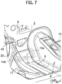
- the other ends 15b of the dash lower cross members 15 are connected also to vehicle interior on-floor members 17 provided in accordance with the roots 14a of the front side members 14 as shown in Figs. 6 and 7 .
- portions excluding the one ends 15a and the other ends 15b of the flanges 16 of the dash lower cross members 15 are spot-welded and connected to the dash panel 5.
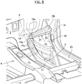
- the upper dash cross members 19 each have a body 20 having a cross-section of substantially trapezoidal shape, and a flange 21 formed on an outer periphery of the body 20.
- One ends 19a of the upper dash cross members 19 each having a rectangular shape in a plane view are spot-welded and connected to the dash panel 5 near the lower end roots 14a of the front side members 14.
- other ends 19b of the upper dash cross members 19 are spot-welded and connected to the dash side panels 18.
- portions excluding the one ends 19a and the other ends 19b of the flanges 21 of the upper dash cross members 19 are spot-welded and connected to wheel house panels 22.
- upper dash cross members 19 may be provided on the outside of the vehicle, and that the one ends 19a of the upper dash cross members 19 may be connected to the dash lower cross members 15.
- the lower dash cross members 25 each have a body 26 having a rectangular shape in a plane view, and a flange 27 formed on an outer periphery of the body 26.
- One ends 25a of the lower dash cross members 25 (ends of the flanges 27 located on the near sides of the floor tunnel 4) are spot-welded and connected to the front end parts 17a of the vehicle interior on-floor members 17 provided in accordance with the lower end roots 14a of the front side members 14.
- the other ends 25b of the lower dash cross members 25 (ends of the flanges 27 located on the far sides of the floor tunnel 4) are spot-welded and connected to the vehicle front end parts 23a of the side sills 23.
- portions excluding the one ends 25a and the other ends 25b of the flanges 27 of the lower dash cross members 25 are spot-welded and connected to the wheel house panels 22.
- lower dash cross members 25 may be provided on the outside of the vehicle, and that the one ends 25a of the lower dash cross members 25 may be connected to the dash lower cross members 15.
- the outside of the vehicle of the vehicle body front section structure including the first to fourth vehicle body front section reinforcing members mentioned above is configured so that the U-shaped member 8 covers a whole of a floor tunnel front end part and is connected to the floor tunnel members 7, and so that the dash lower cross members 15 are connected to the U-shaped member 8 and the roots 14a of the front side members 14.
- the vehicle body front section structure is configured so that the U-shaped member 8 is connected to frame members which are the floor tunnel members 7, and so that the dash lower cross members 15 are connected to frame members which are the front side members 14.
- an inside of the vehicle interior of the vehicle body front section structure including the first to fourth vehicle body front section reinforcing members has a structure that the upper dash cross members 19 are connected to the frame members which are the front side members 14 and also to the dash side panels 18, and that the lower dash cross members 25 are connected to frame members which are the vehicle interior on-floor members 17 and the side sills 23.
- the U-shaped member 8 which is the first vehicle body front section reinforcing member directly covers the whole of a floor tunnel front end part, strength at the front end of the floor tunnel 4 can be improved. As a result, vehicle body deformation can be suppressed, and sound vibration performance can be improved.
- the first vehicle body front section reinforcing member enhances rigidity of the floor tunnel front end part, shear and a torsional stress due to crushing deformation of the floor tunnel front end part can be directly suppressed. As a result, the vehicle body deformation is suppressed, and the sound vibration performance is improved.
- the U-shaped member 8 is connected to frame members which are the floor tunnel members 7, the floor tunnel members 7 can be used as a part of a frame structure, and an external force input to the vehicle body 1 can be stress dispersed to the floor tunnel members 7.
- a shear stress and a torsional input which cause crushing deformation in which the floor tunnel front end part collapses in a lateral direction in a frequency range of 100 to 200 Hz of road noise, engine booming noise, etc. are dispersed to the floor tunnel members 7 via the U-shaped member 8, and as a result, crushing deformation occurring at the floor tunnel front end part can be suppressed.
- the dash lower cross members 15, which are the second vehicle body front section reinforcing members, are connected to the frame members which are the front side members 14, the front side members 14 can be used as a part of the frame structure, and an external force generated in the floor tunnel 4 can be stress dispersed to the front side members 14.
- the dash lower cross members 15 are connected to the U-shaped member 8, strength of the floor tunnel front end part is improved by these dash lower cross members 15 and U-shaped member 8.
- the dash lower cross members 15 are connected to the lower dash cross members 25 through the vehicle interior on-floor members 17 so as to stress disperse to those members.
- the upper dash cross members 19, which are the third vehicle body front section reinforcing members, are coupled to the vicinities of the lower end roots 14a of the front side members 14, the front side members 14 can be used as the part of the frame structure, and an external force input to the vehicle body can be stress dispersed to the front side members 14.
- the upper dash cross members 19 are coupled to the dash side panels 18, the external force generated in the floor tunnel 4 can be dispersed to the dash side panels 18.
- the lower dash cross members 25, which are the fourth vehicle body front section reinforcing members, are connected to the lower end roots 14a of the front side members 14, the front side members 14 can be used as the part of the frame structure, and the external force generated in the floor tunnel 4 can be stress dispersed to the front side members 14.
- the lower dash cross members 25 are connected to the side sills 23, the external force generated in the floor tunnel 4 can be dispersed to the side sills 23 through the lower dash cross members 25.
- the vehicle interior on-floor members 17 can be used as a part of the frame structure, and the external force generated in the floor tunnel 4 can be stress dispersed to the vehicle interior on-floor members 17.
- the external force input to the vehicle body 1 is dispersed to the whole of a frame structure included in the vehicle body, and the external force that was input does not concentrate on specific portion.
- the force generated in the floor tunnel 4 is dispersed, and such crushing deformation that the floor tunnel front end part and the floor tunnel 4 collapse in the lateral direction can be suppressed. Since a deformation mode of the frame structure accompanied by a change in volume of air in the vehicle interior is suppressed, increase of a noise level in the vehicle interior can be effectively suppressed.
- the present invention can be utilized for a vehicle having a floor tunnel.
Landscapes
- Engineering & Computer Science (AREA)
- Chemical & Material Sciences (AREA)
- Combustion & Propulsion (AREA)
- Transportation (AREA)
- Mechanical Engineering (AREA)
- Body Structure For Vehicles (AREA)
Applications Claiming Priority (2)
| Application Number | Priority Date | Filing Date | Title |
|---|---|---|---|
| JP2013138613 | 2013-07-02 | ||
| PCT/JP2014/066288 WO2015001973A1 (ja) | 2013-07-02 | 2014-06-19 | 車体前部構造 |
Publications (3)
| Publication Number | Publication Date |
|---|---|
| EP3018041A1 EP3018041A1 (en) | 2016-05-11 |
| EP3018041A4 EP3018041A4 (en) | 2017-06-07 |
| EP3018041B1 true EP3018041B1 (en) | 2018-05-02 |
Family
ID=52143551
Family Applications (1)
| Application Number | Title | Priority Date | Filing Date |
|---|---|---|---|
| EP14818852.7A Active EP3018041B1 (en) | 2013-07-02 | 2014-06-19 | Vehicle body front section structure |
Country Status (9)
| Country | Link |
|---|---|
| US (1) | US9643659B2 (pt) |
| EP (1) | EP3018041B1 (pt) |
| JP (1) | JP6041054B2 (pt) |
| CN (1) | CN105517882B (pt) |
| BR (1) | BR112015032835B1 (pt) |
| MX (1) | MX345882B (pt) |
| MY (1) | MY161701A (pt) |
| RU (1) | RU2615237C1 (pt) |
| WO (1) | WO2015001973A1 (pt) |
Families Citing this family (21)
| Publication number | Priority date | Publication date | Assignee | Title |
|---|---|---|---|---|
| KR101711170B1 (ko) * | 2009-06-23 | 2017-02-28 | 오토믹 에너지 오브 캐나다 리미티드 | 원주방향 샘플링 도구 |
| JP6522982B2 (ja) * | 2015-02-18 | 2019-05-29 | 本田技研工業株式会社 | 車体構造 |
| JP6368851B2 (ja) * | 2015-03-17 | 2018-08-01 | 本田技研工業株式会社 | 車体構造 |
| JP2017024698A (ja) * | 2015-07-15 | 2017-02-02 | 現代自動車株式会社Hyundai Motor Company | 車体結合構造 |
| KR101786665B1 (ko) * | 2015-12-08 | 2017-10-19 | 현대자동차 주식회사 | 자동차용 리어 플로어 보강 구조 |
| KR101816378B1 (ko) * | 2016-01-29 | 2018-01-08 | 현대자동차주식회사 | 컬럼다이브 방지를 위한 패널조립체 구조 |
| CN105667604A (zh) * | 2016-03-31 | 2016-06-15 | 上海长安汽车工程技术有限公司 | 汽车前围板和前地板的加强结构 |
| CN105946981B (zh) * | 2016-06-14 | 2018-05-04 | 重庆长安汽车股份有限公司 | 一种贯通前壁板和前地板的加强结构 |
| JP6547772B2 (ja) * | 2017-01-24 | 2019-07-24 | トヨタ自動車株式会社 | 車両フロア構造 |
| KR102354133B1 (ko) * | 2017-07-12 | 2022-01-24 | 현대자동차주식회사 | 차량용 대쉬 패널 지지 구조체 |
| JP6532513B2 (ja) * | 2017-09-15 | 2019-06-19 | 本田技研工業株式会社 | 車体構造 |
| KR102383247B1 (ko) * | 2017-10-11 | 2022-04-05 | 현대자동차 주식회사 | 전방 차체 보강구조 |
| KR102440606B1 (ko) * | 2017-12-15 | 2022-09-05 | 현대자동차 주식회사 | 전방 차체 보강구조 |
| JP6881325B2 (ja) * | 2018-01-16 | 2021-06-02 | マツダ株式会社 | 下部車体構造 |
| CN108454705A (zh) * | 2018-03-26 | 2018-08-28 | 力帆实业(集团)股份有限公司 | 汽车前围板总成 |
| JP6881397B2 (ja) * | 2018-06-15 | 2021-06-02 | マツダ株式会社 | 下部車体構造 |
| JP6881404B2 (ja) * | 2018-08-13 | 2021-06-02 | マツダ株式会社 | 下部車体構造 |
| CN110857121B (zh) * | 2018-08-23 | 2021-11-12 | 比亚迪股份有限公司 | 正面碰撞传力机构和具有其的车辆 |
| WO2020217085A1 (en) * | 2019-04-23 | 2020-10-29 | Arcelormittal | Tunnel having integrated lateral reinforcements |
| JP7243438B2 (ja) * | 2019-05-22 | 2023-03-22 | トヨタ自動車株式会社 | 車両前部構造 |
| CN115107881A (zh) * | 2021-03-18 | 2022-09-27 | 本田技研工业株式会社 | 车体面板结构 |
Family Cites Families (17)
| Publication number | Priority date | Publication date | Assignee | Title |
|---|---|---|---|---|
| JPH018462Y2 (pt) * | 1984-10-16 | 1989-03-07 | ||
| JPS62181976A (ja) * | 1986-02-06 | 1987-08-10 | Mazda Motor Corp | 自動車の下部車体構造 |
| JPH0625414Y2 (ja) * | 1987-09-29 | 1994-07-06 | 三菱自動車工業株式会社 | 自動車用ボデー前部結合構造 |
| JP2936877B2 (ja) * | 1992-03-25 | 1999-08-23 | トヨタ自動車株式会社 | 自動車の車体前部構造 |
| DE10232841A1 (de) | 2002-07-19 | 2004-02-05 | Volkswagen Ag | Bodenträgeranordnung an Kraftfahrzeugen |
| JP4483592B2 (ja) * | 2005-01-14 | 2010-06-16 | トヨタ自動車株式会社 | ダッシュパネル補強構造 |
| TWI361766B (en) * | 2007-07-12 | 2012-04-11 | Honda Motor Co Ltd | Vehicle body frame structure |
| JP2009248593A (ja) * | 2008-04-01 | 2009-10-29 | Toyota Motor Corp | 車体骨格構造 |
| CN201405934Y (zh) * | 2009-03-12 | 2010-02-17 | 中通客车控股股份有限公司 | 大型矩形管底架的大客车全承载车身 |
| US8292356B2 (en) * | 2009-03-17 | 2012-10-23 | Mazda Motor Corporation | Lower vehicle-body structure of vehicle |
| JP5510778B2 (ja) * | 2009-05-15 | 2014-06-04 | スズキ株式会社 | ダッシュパネル周辺の車体構造 |
| CA2779192C (en) * | 2009-11-05 | 2013-07-02 | Honda Motor Co., Ltd. | Vehicle body structure |
| DE102009056840A1 (de) * | 2009-12-03 | 2011-06-09 | GM Global Technology Operations LLC, ( n. d. Ges. d. Staates Delaware ), Detroit | Unterbaustruktur einer Kraftfahrzeugkarosserie |
| JP5560328B2 (ja) * | 2010-05-25 | 2014-07-23 | 本田技研工業株式会社 | 前部車体構造 |
| CN103339019B (zh) * | 2011-01-26 | 2015-11-25 | 本田技研工业株式会社 | 车身前部结构 |
| CN102938450B (zh) * | 2011-08-16 | 2015-11-25 | 上海通用汽车有限公司 | 车用电池箱、车身构件及汽车 |
| JP5738163B2 (ja) * | 2011-12-15 | 2015-06-17 | 本田技研工業株式会社 | 車体構造 |
-
2014
- 2014-06-19 MY MYPI2015704700A patent/MY161701A/en unknown
- 2014-06-19 JP JP2015525138A patent/JP6041054B2/ja active Active
- 2014-06-19 US US14/902,474 patent/US9643659B2/en active Active
- 2014-06-19 MX MX2015017584A patent/MX345882B/es active IP Right Grant
- 2014-06-19 EP EP14818852.7A patent/EP3018041B1/en active Active
- 2014-06-19 BR BR112015032835-0A patent/BR112015032835B1/pt active IP Right Grant
- 2014-06-19 CN CN201480048414.XA patent/CN105517882B/zh active Active
- 2014-06-19 WO PCT/JP2014/066288 patent/WO2015001973A1/ja active Application Filing
- 2014-06-19 RU RU2016103130A patent/RU2615237C1/ru active
Non-Patent Citations (1)
| Title |
|---|
| None * |
Also Published As
| Publication number | Publication date |
|---|---|
| JP6041054B2 (ja) | 2016-12-07 |
| MX2015017584A (es) | 2016-04-07 |
| WO2015001973A1 (ja) | 2015-01-08 |
| JPWO2015001973A1 (ja) | 2017-02-23 |
| MY161701A (en) | 2017-05-15 |
| CN105517882B (zh) | 2017-04-12 |
| BR112015032835A2 (pt) | 2020-04-28 |
| US9643659B2 (en) | 2017-05-09 |
| MX345882B (es) | 2017-02-22 |
| BR112015032835B1 (pt) | 2022-04-19 |
| EP3018041A1 (en) | 2016-05-11 |
| CN105517882A (zh) | 2016-04-20 |
| EP3018041A4 (en) | 2017-06-07 |
| RU2615237C1 (ru) | 2017-04-04 |
| US20170001669A1 (en) | 2017-01-05 |
Similar Documents
| Publication | Publication Date | Title |
|---|---|---|
| EP3018041B1 (en) | Vehicle body front section structure | |
| CN110352157B (zh) | 车辆的下部车身结构 | |
| US9764765B2 (en) | Vehicle-body front structure | |
| EP3063052B1 (en) | Suspension tower and vehicle front structure | |
| JP4858183B2 (ja) | 車体下部構造 | |
| JP6052408B2 (ja) | 車体の前部構造 | |
| EP3042832A1 (en) | Vehicle body structure | |
| JP6511078B2 (ja) | 電気自動車のフロア構造 | |
| WO2012121142A1 (ja) | 車体後部構造 | |
| JP2019006311A (ja) | 車体前部構造 | |
| JP2016002871A (ja) | 車両前部構造 | |
| JP6584457B2 (ja) | 車体前部構造 | |
| JP2019171934A (ja) | 車両の前部車体構造 | |
| JP6181099B2 (ja) | 車体の後部構造 | |
| JP2019171932A (ja) | 車両の前部車体構造 | |
| JP2019171933A (ja) | 車両の前部車体構造 | |
| JP2017039352A (ja) | 車両前部構造 | |
| JP5825220B2 (ja) | 車体前部構造 | |
| JP6717027B2 (ja) | 車体の前部構造 | |
| WO2014199755A1 (ja) | 車体側部構造 | |
| JP2009280106A (ja) | 車両用フレーム構造 | |
| EP3702249A1 (en) | Vehicle body structure and method of producing the same | |
| JP6525243B2 (ja) | 車両のハイルーフ取付構造 | |
| JP5513904B2 (ja) | 車両の前部車体構造 | |
| JP5496727B2 (ja) | 自動車の前部車体構造 |
Legal Events
| Date | Code | Title | Description |
|---|---|---|---|
| PUAI | Public reference made under article 153(3) epc to a published international application that has entered the european phase |
Free format text: ORIGINAL CODE: 0009012 |
|
| 17P | Request for examination filed |
Effective date: 20160129 |
|
| AK | Designated contracting states |
Kind code of ref document: A1 Designated state(s): AL AT BE BG CH CY CZ DE DK EE ES FI FR GB GR HR HU IE IS IT LI LT LU LV MC MK MT NL NO PL PT RO RS SE SI SK SM TR |
|
| AX | Request for extension of the european patent |
Extension state: BA ME |
|
| DAX | Request for extension of the european patent (deleted) | ||
| A4 | Supplementary search report drawn up and despatched |
Effective date: 20170509 |
|
| RIC1 | Information provided on ipc code assigned before grant |
Ipc: B62D 25/20 20060101AFI20170502BHEP Ipc: B62D 25/14 20060101ALI20170502BHEP Ipc: B62D 25/08 20060101ALI20170502BHEP |
|
| GRAP | Despatch of communication of intention to grant a patent |
Free format text: ORIGINAL CODE: EPIDOSNIGR1 |
|
| STAA | Information on the status of an ep patent application or granted ep patent |
Free format text: STATUS: GRANT OF PATENT IS INTENDED |
|
| INTG | Intention to grant announced |
Effective date: 20180207 |
|
| RIN1 | Information on inventor provided before grant (corrected) |
Inventor name: MORITA, YUKIO Inventor name: KANEDA, TOMOYUKI Inventor name: OHIGASHI, AKIRA |
|
| GRAS | Grant fee paid |
Free format text: ORIGINAL CODE: EPIDOSNIGR3 |
|
| GRAA | (expected) grant |
Free format text: ORIGINAL CODE: 0009210 |
|
| STAA | Information on the status of an ep patent application or granted ep patent |
Free format text: STATUS: THE PATENT HAS BEEN GRANTED |
|
| AK | Designated contracting states |
Kind code of ref document: B1 Designated state(s): AL AT BE BG CH CY CZ DE DK EE ES FI FR GB GR HR HU IE IS IT LI LT LU LV MC MK MT NL NO PL PT RO RS SE SI SK SM TR |
|
| REG | Reference to a national code |
Ref country code: GB Ref legal event code: FG4D |
|
| REG | Reference to a national code |
Ref country code: CH Ref legal event code: EP Ref country code: AT Ref legal event code: REF Ref document number: 994906 Country of ref document: AT Kind code of ref document: T Effective date: 20180515 |
|
| REG | Reference to a national code |
Ref country code: DE Ref legal event code: R096 Ref document number: 602014025000 Country of ref document: DE Ref country code: IE Ref legal event code: FG4D |
|
| REG | Reference to a national code |
Ref country code: FR Ref legal event code: PLFP Year of fee payment: 5 |
|
| REG | Reference to a national code |
Ref country code: NL Ref legal event code: MP Effective date: 20180502 |
|
| REG | Reference to a national code |
Ref country code: LT Ref legal event code: MG4D |
|
| PG25 | Lapsed in a contracting state [announced via postgrant information from national office to epo] |
Ref country code: LT Free format text: LAPSE BECAUSE OF FAILURE TO SUBMIT A TRANSLATION OF THE DESCRIPTION OR TO PAY THE FEE WITHIN THE PRESCRIBED TIME-LIMIT Effective date: 20180502 Ref country code: NO Free format text: LAPSE BECAUSE OF FAILURE TO SUBMIT A TRANSLATION OF THE DESCRIPTION OR TO PAY THE FEE WITHIN THE PRESCRIBED TIME-LIMIT Effective date: 20180802 Ref country code: BG Free format text: LAPSE BECAUSE OF FAILURE TO SUBMIT A TRANSLATION OF THE DESCRIPTION OR TO PAY THE FEE WITHIN THE PRESCRIBED TIME-LIMIT Effective date: 20180802 Ref country code: SE Free format text: LAPSE BECAUSE OF FAILURE TO SUBMIT A TRANSLATION OF THE DESCRIPTION OR TO PAY THE FEE WITHIN THE PRESCRIBED TIME-LIMIT Effective date: 20180502 Ref country code: FI Free format text: LAPSE BECAUSE OF FAILURE TO SUBMIT A TRANSLATION OF THE DESCRIPTION OR TO PAY THE FEE WITHIN THE PRESCRIBED TIME-LIMIT Effective date: 20180502 Ref country code: ES Free format text: LAPSE BECAUSE OF FAILURE TO SUBMIT A TRANSLATION OF THE DESCRIPTION OR TO PAY THE FEE WITHIN THE PRESCRIBED TIME-LIMIT Effective date: 20180502 |
|
| PG25 | Lapsed in a contracting state [announced via postgrant information from national office to epo] |
Ref country code: NL Free format text: LAPSE BECAUSE OF FAILURE TO SUBMIT A TRANSLATION OF THE DESCRIPTION OR TO PAY THE FEE WITHIN THE PRESCRIBED TIME-LIMIT Effective date: 20180502 Ref country code: HR Free format text: LAPSE BECAUSE OF FAILURE TO SUBMIT A TRANSLATION OF THE DESCRIPTION OR TO PAY THE FEE WITHIN THE PRESCRIBED TIME-LIMIT Effective date: 20180502 Ref country code: GR Free format text: LAPSE BECAUSE OF FAILURE TO SUBMIT A TRANSLATION OF THE DESCRIPTION OR TO PAY THE FEE WITHIN THE PRESCRIBED TIME-LIMIT Effective date: 20180803 Ref country code: LV Free format text: LAPSE BECAUSE OF FAILURE TO SUBMIT A TRANSLATION OF THE DESCRIPTION OR TO PAY THE FEE WITHIN THE PRESCRIBED TIME-LIMIT Effective date: 20180502 Ref country code: RS Free format text: LAPSE BECAUSE OF FAILURE TO SUBMIT A TRANSLATION OF THE DESCRIPTION OR TO PAY THE FEE WITHIN THE PRESCRIBED TIME-LIMIT Effective date: 20180502 |
|
| REG | Reference to a national code |
Ref country code: AT Ref legal event code: MK05 Ref document number: 994906 Country of ref document: AT Kind code of ref document: T Effective date: 20180502 |
|
| PG25 | Lapsed in a contracting state [announced via postgrant information from national office to epo] |
Ref country code: AT Free format text: LAPSE BECAUSE OF FAILURE TO SUBMIT A TRANSLATION OF THE DESCRIPTION OR TO PAY THE FEE WITHIN THE PRESCRIBED TIME-LIMIT Effective date: 20180502 Ref country code: DK Free format text: LAPSE BECAUSE OF FAILURE TO SUBMIT A TRANSLATION OF THE DESCRIPTION OR TO PAY THE FEE WITHIN THE PRESCRIBED TIME-LIMIT Effective date: 20180502 Ref country code: EE Free format text: LAPSE BECAUSE OF FAILURE TO SUBMIT A TRANSLATION OF THE DESCRIPTION OR TO PAY THE FEE WITHIN THE PRESCRIBED TIME-LIMIT Effective date: 20180502 Ref country code: CZ Free format text: LAPSE BECAUSE OF FAILURE TO SUBMIT A TRANSLATION OF THE DESCRIPTION OR TO PAY THE FEE WITHIN THE PRESCRIBED TIME-LIMIT Effective date: 20180502 Ref country code: RO Free format text: LAPSE BECAUSE OF FAILURE TO SUBMIT A TRANSLATION OF THE DESCRIPTION OR TO PAY THE FEE WITHIN THE PRESCRIBED TIME-LIMIT Effective date: 20180502 Ref country code: PL Free format text: LAPSE BECAUSE OF FAILURE TO SUBMIT A TRANSLATION OF THE DESCRIPTION OR TO PAY THE FEE WITHIN THE PRESCRIBED TIME-LIMIT Effective date: 20180502 Ref country code: SK Free format text: LAPSE BECAUSE OF FAILURE TO SUBMIT A TRANSLATION OF THE DESCRIPTION OR TO PAY THE FEE WITHIN THE PRESCRIBED TIME-LIMIT Effective date: 20180502 |
|
| REG | Reference to a national code |
Ref country code: CH Ref legal event code: PL |
|
| REG | Reference to a national code |
Ref country code: DE Ref legal event code: R097 Ref document number: 602014025000 Country of ref document: DE |
|
| PG25 | Lapsed in a contracting state [announced via postgrant information from national office to epo] |
Ref country code: SM Free format text: LAPSE BECAUSE OF FAILURE TO SUBMIT A TRANSLATION OF THE DESCRIPTION OR TO PAY THE FEE WITHIN THE PRESCRIBED TIME-LIMIT Effective date: 20180502 Ref country code: IT Free format text: LAPSE BECAUSE OF FAILURE TO SUBMIT A TRANSLATION OF THE DESCRIPTION OR TO PAY THE FEE WITHIN THE PRESCRIBED TIME-LIMIT Effective date: 20180502 |
|
| REG | Reference to a national code |
Ref country code: BE Ref legal event code: MM Effective date: 20180630 |
|
| PLBE | No opposition filed within time limit |
Free format text: ORIGINAL CODE: 0009261 |
|
| STAA | Information on the status of an ep patent application or granted ep patent |
Free format text: STATUS: NO OPPOSITION FILED WITHIN TIME LIMIT |
|
| REG | Reference to a national code |
Ref country code: IE Ref legal event code: MM4A |
|
| PG25 | Lapsed in a contracting state [announced via postgrant information from national office to epo] |
Ref country code: MC Free format text: LAPSE BECAUSE OF FAILURE TO SUBMIT A TRANSLATION OF THE DESCRIPTION OR TO PAY THE FEE WITHIN THE PRESCRIBED TIME-LIMIT Effective date: 20180502 Ref country code: LU Free format text: LAPSE BECAUSE OF NON-PAYMENT OF DUE FEES Effective date: 20180619 |
|
| 26N | No opposition filed |
Effective date: 20190205 |
|
| PG25 | Lapsed in a contracting state [announced via postgrant information from national office to epo] |
Ref country code: IE Free format text: LAPSE BECAUSE OF NON-PAYMENT OF DUE FEES Effective date: 20180619 Ref country code: LI Free format text: LAPSE BECAUSE OF NON-PAYMENT OF DUE FEES Effective date: 20180630 Ref country code: CH Free format text: LAPSE BECAUSE OF NON-PAYMENT OF DUE FEES Effective date: 20180630 |
|
| PG25 | Lapsed in a contracting state [announced via postgrant information from national office to epo] |
Ref country code: SI Free format text: LAPSE BECAUSE OF FAILURE TO SUBMIT A TRANSLATION OF THE DESCRIPTION OR TO PAY THE FEE WITHIN THE PRESCRIBED TIME-LIMIT Effective date: 20180502 Ref country code: BE Free format text: LAPSE BECAUSE OF NON-PAYMENT OF DUE FEES Effective date: 20180630 |
|
| PG25 | Lapsed in a contracting state [announced via postgrant information from national office to epo] |
Ref country code: AL Free format text: LAPSE BECAUSE OF FAILURE TO SUBMIT A TRANSLATION OF THE DESCRIPTION OR TO PAY THE FEE WITHIN THE PRESCRIBED TIME-LIMIT Effective date: 20180502 |
|
| PG25 | Lapsed in a contracting state [announced via postgrant information from national office to epo] |
Ref country code: MT Free format text: LAPSE BECAUSE OF NON-PAYMENT OF DUE FEES Effective date: 20180619 |
|
| PG25 | Lapsed in a contracting state [announced via postgrant information from national office to epo] |
Ref country code: TR Free format text: LAPSE BECAUSE OF FAILURE TO SUBMIT A TRANSLATION OF THE DESCRIPTION OR TO PAY THE FEE WITHIN THE PRESCRIBED TIME-LIMIT Effective date: 20180502 |
|
| PG25 | Lapsed in a contracting state [announced via postgrant information from national office to epo] |
Ref country code: PT Free format text: LAPSE BECAUSE OF FAILURE TO SUBMIT A TRANSLATION OF THE DESCRIPTION OR TO PAY THE FEE WITHIN THE PRESCRIBED TIME-LIMIT Effective date: 20180502 |
|
| PG25 | Lapsed in a contracting state [announced via postgrant information from national office to epo] |
Ref country code: HU Free format text: LAPSE BECAUSE OF FAILURE TO SUBMIT A TRANSLATION OF THE DESCRIPTION OR TO PAY THE FEE WITHIN THE PRESCRIBED TIME-LIMIT; INVALID AB INITIO Effective date: 20140619 Ref country code: CY Free format text: LAPSE BECAUSE OF FAILURE TO SUBMIT A TRANSLATION OF THE DESCRIPTION OR TO PAY THE FEE WITHIN THE PRESCRIBED TIME-LIMIT Effective date: 20180502 Ref country code: MK Free format text: LAPSE BECAUSE OF NON-PAYMENT OF DUE FEES Effective date: 20180502 |
|
| PG25 | Lapsed in a contracting state [announced via postgrant information from national office to epo] |
Ref country code: IS Free format text: LAPSE BECAUSE OF FAILURE TO SUBMIT A TRANSLATION OF THE DESCRIPTION OR TO PAY THE FEE WITHIN THE PRESCRIBED TIME-LIMIT Effective date: 20180902 |
|
| PGFP | Annual fee paid to national office [announced via postgrant information from national office to epo] |
Ref country code: FR Payment date: 20230523 Year of fee payment: 10 Ref country code: DE Payment date: 20230523 Year of fee payment: 10 |
|
| REG | Reference to a national code |
Ref country code: DE Ref legal event code: R084 Ref document number: 602014025000 Country of ref document: DE |
|
| REG | Reference to a national code |
Ref country code: GB Ref legal event code: 746 Effective date: 20230926 |
|
| PGFP | Annual fee paid to national office [announced via postgrant information from national office to epo] |
Ref country code: GB Payment date: 20230524 Year of fee payment: 10 |