EP3018041B1 - Vehicle body front section structure - Google Patents
Vehicle body front section structure Download PDFInfo
- Publication number
- EP3018041B1 EP3018041B1 EP14818852.7A EP14818852A EP3018041B1 EP 3018041 B1 EP3018041 B1 EP 3018041B1 EP 14818852 A EP14818852 A EP 14818852A EP 3018041 B1 EP3018041 B1 EP 3018041B1
- Authority
- EP
- European Patent Office
- Prior art keywords
- vehicle body
- vehicle
- front section
- floor tunnel
- members
- Prior art date
- Legal status (The legal status is an assumption and is not a legal conclusion. Google has not performed a legal analysis and makes no representation as to the accuracy of the status listed.)
- Active
Links
- 230000003014 reinforcing effect Effects 0.000 claims description 34
- 229910000831 Steel Inorganic materials 0.000 description 1
- 239000012141 concentrate Substances 0.000 description 1
- 239000006185 dispersion Substances 0.000 description 1
- 238000005516 engineering process Methods 0.000 description 1
- 238000000465 moulding Methods 0.000 description 1
- 230000002093 peripheral effect Effects 0.000 description 1
- 238000009751 slip forming Methods 0.000 description 1
- 239000010959 steel Substances 0.000 description 1
Images


Classifications
-
- B—PERFORMING OPERATIONS; TRANSPORTING
- B62—LAND VEHICLES FOR TRAVELLING OTHERWISE THAN ON RAILS
- B62D—MOTOR VEHICLES; TRAILERS
- B62D25/00—Superstructure or monocoque structure sub-units; Parts or details thereof not otherwise provided for
- B62D25/20—Floors or bottom sub-units
- B62D25/2009—Floors or bottom sub-units in connection with other superstructure subunits
- B62D25/2018—Floors or bottom sub-units in connection with other superstructure subunits the subunits being front structures
-
- B—PERFORMING OPERATIONS; TRANSPORTING
- B62—LAND VEHICLES FOR TRAVELLING OTHERWISE THAN ON RAILS
- B62D—MOTOR VEHICLES; TRAILERS
- B62D25/00—Superstructure or monocoque structure sub-units; Parts or details thereof not otherwise provided for
- B62D25/20—Floors or bottom sub-units
-
- B—PERFORMING OPERATIONS; TRANSPORTING
- B62—LAND VEHICLES FOR TRAVELLING OTHERWISE THAN ON RAILS
- B62D—MOTOR VEHICLES; TRAILERS
- B62D25/00—Superstructure or monocoque structure sub-units; Parts or details thereof not otherwise provided for
- B62D25/08—Front or rear portions
- B62D25/088—Details of structures as upper supports for springs or dampers
-
- B—PERFORMING OPERATIONS; TRANSPORTING
- B62—LAND VEHICLES FOR TRAVELLING OTHERWISE THAN ON RAILS
- B62D—MOTOR VEHICLES; TRAILERS
- B62D25/00—Superstructure or monocoque structure sub-units; Parts or details thereof not otherwise provided for
- B62D25/08—Front or rear portions
- B62D25/14—Dashboards as superstructure sub-units
-
- B—PERFORMING OPERATIONS; TRANSPORTING
- B62—LAND VEHICLES FOR TRAVELLING OTHERWISE THAN ON RAILS
- B62D—MOTOR VEHICLES; TRAILERS
- B62D25/00—Superstructure or monocoque structure sub-units; Parts or details thereof not otherwise provided for
- B62D25/20—Floors or bottom sub-units
- B62D25/2009—Floors or bottom sub-units in connection with other superstructure subunits
- B62D25/2036—Floors or bottom sub-units in connection with other superstructure subunits the subunits being side panels, sills or pillars
-
- B—PERFORMING OPERATIONS; TRANSPORTING
- B62—LAND VEHICLES FOR TRAVELLING OTHERWISE THAN ON RAILS
- B62D—MOTOR VEHICLES; TRAILERS
- B62D25/00—Superstructure or monocoque structure sub-units; Parts or details thereof not otherwise provided for
- B62D25/20—Floors or bottom sub-units
- B62D25/2009—Floors or bottom sub-units in connection with other superstructure subunits
- B62D25/2045—Floors or bottom sub-units in connection with other superstructure subunits the subunits being fire walls
-
- B—PERFORMING OPERATIONS; TRANSPORTING
- B62—LAND VEHICLES FOR TRAVELLING OTHERWISE THAN ON RAILS
- B62D—MOTOR VEHICLES; TRAILERS
- B62D27/00—Connections between superstructure or understructure sub-units
- B62D27/02—Connections between superstructure or understructure sub-units rigid
Definitions
- the present invention relates to a vehicle body front section structure.
- Patent Literature 1 has referred to a floor cross member set for the purpose of improving collision performance, particularly front surface collision performance.
- a vehicle body front section structure is configured so as to take a shape to cover a dash panel and a floor connecting part from an inside of a vehicle interior by the floor cross member, and so as to continuously connect among side sills. Accordingly, according to a structure of Patent Literature 1, sufficient vehicle body rigidity can be secured in order to suppress vehicle body deformation of a cabin at the time of front surface collision, and collision energy can be absorbed in a wide range using even side sill parts.
- Patent Literature 1 U.S. Patent No. 2005-0140179A1 Specification
- Patent Literature 2 JP H06 25414 Y2
- Patent Literature 3 JP S61 71577 U .
- a peripheral structure from a dash panel to a floor tunnel is one of important structure portions that affect collision, sound vibration, and driving stability performance, respectively.
- joint rigidity between the dash panel and the floor tunnel is important.
- deformation hereinafter referred to as crushing deformation
- a front end part of the floor tunnel collapses in a lateral direction.
- Patent Literature 1 a space between a side surface of the floor tunnel and the floor cross member is small, and a cross section sufficient to suppress the crushing deformation is not sufficiently secured. Therefore, the side surface of the floor tunnel to suppress the crushing deformation does not have sufficient rigidity, and additionally, a frame structure of the floor cross member cannot disperse a force acting on a floor tunnel member at the time of the crushing deformation. As a result, the structure of Patent Literature 1 causes vehicle body deformation to thereby increase the noise level in the vehicle interior.
- the present invention provides a vehicle body front section structure that can suppress vehicle body deformation to thereby improve sound vibration performance.
- the vehicle body front section structure of the present invention includes a floor tunnel formed in a vehicle longitudinal direction so as to project into a vehicle interior on an underfloor of the vehicle, and a first vehicle body front section reinforcing member that covers , from an outside of the vehicle, a whole of a floor tunnel front end part being a vehicle front of the floor tunnel , from a vehicle upper end to a root of each floor tunnel member provided in the vehicle longitudinal direction along a front end ridge line part.
- Fig. 1 is a perspective view showing structures of a front section and a lower section seen from an outside of a vehicle in a vehicle body front section structure seen from the outside of the vehicle (a perspective view in a case of looking up at a vehicle lower section from a position of a vehicle front lower part).
- Fig. 2 is a perspective view showing a structure in a vehicle interior of the vehicle body front section structure (a perspective view in a case of looking into an inside of the vehicle interior from a position of a side surface of the vehicle). Note that in Figs. 1 and 2 , an arrow FR indicates a vehicle front, an arrow RR a vehicle rear, an arrow H a vehicle height, and an arrow W a vehicle width direction, respectively.
- a floor tunnel 4 is formed on an underfloor 2 of a vehicle body 1 so as to project into a vehicle interior 3.
- the floor tunnel 4 is continuously formed on a center in the vehicle width direction W along a vehicle longitudinal direction from a portion where a dash panel 5 and a floor panel 6 cross with each other to the vehicle rear RR.
- a front end ridge line part 1a is located at the portion where the dash panel 5 and the floor panel 6 cross with each other, and the dash panel 5 and the floor panel 6 are coupled to each other by the front end ridge line part 1a.
- first to fourth vehicle body front section reinforcing members for reinforcing strength in a front end portion of the floor tunnel 4 are provided in this vehicle body 1, and these four reinforcing members constitute a part of the vehicle body front section structure.
- a U-shaped member 8 which is the first vehicle body front section reinforcing member included in the vehicle body front section structure, is attached to a front end part of the floor tunnel in a vehicle front FR direction of the floor tunnel 4 from the outside of the vehicle as shown in Fig. 1 .
- the U-shaped member 8 is attached so as to cover the front end ridge line part 1a from the outside of the vehicle.
- the U-shaped member 8 covers a whole of a front end ridge line part 1a from an end of the vehicle upper end side of the front end ridge line part 1a toward roots 7a of a pair of floor tunnel members 7 provided in the vehicle longitudinal direction.
- the pair of floor tunnel members 7 couple the floor tunnel 4 to the floor panel 6.
- a whole shape of the U-shaped member 8 is an inverted U-shape that opens to a vehicle lower part, and the U-shaped member 8 has a U-shaped part 8a, a pair of extended parts 8b, and a pair of floor tunnel member connecting parts 8c.
- the U-shaped part 8a is formed in conformity with a U-shape of the floor tunnel 4, and the pair of extended parts 8b extend from a front end of the U-shaped part 8a, i.e., an end of the vehicle upper end side of the U-shaped part 8a, to the pair of floor tunnel members 7.
- the floor tunnel member connecting part 8c is provided at a front end of the each extended part 8b.
- the U-shaped part 8a, the pair of extended parts 8b, and the pair of floor tunnel member connecting parts 8c are integrally formed by press-molding of a steel plate, and they integrally constitute the U-shaped member 8.
- a connecting part to the vehicle body 1 of the U-shaped member 8 includes three parts of an outer periphery, an inner periphery, and ends.
- a flange 9 integrally formed therein that continues the U-shaped part 8a, the pair of extended parts 8b, and the pair of floor tunnel member connecting parts 8c are integrally formed at the U-shaped member 8.
- the flange 9 corresponds to the outer periphery of the connecting part to the vehicle body 1 of the U-shaped member 8.
- the outer periphery of the U-shaped member 8 is divided into a portion where three of the dash panel 5, a floor tunnel front end panel 10, and the flange 9 are stacked and connected, and a portion where two of a front floor panel 11 and the flange 9 are stacked and connected.
- a bent part 13 made into a shape conforming to a front end side surface part 12 of the floor tunnel 4 is integrally formed at the U-shaped member 8.
- the bent part 13 corresponds to the inner periphery of the connecting part to the vehicle body 1 of the U-shaped member 8.
- the bent part 13 is spot-welded and connected to the above-mentioned front end side surface 12 of the floor tunnel 4.
- the pair of floor tunnel member connecting parts 8c are integrally formed at the U-shaped member 8.
- the pair of floor tunnel member connecting parts 8c correspond to the ends of the connecting part to the vehicle body 1 of the U-shaped member 8.
- the floor tunnel member connecting parts 8c are spot-welded and connected to the roots 7a, which are front end parts of the floor tunnel members 7.
- the floor tunnel member connecting parts 8c are connected so as to cover the roots 7a of the floor tunnel members 7.
- the U-shaped member 8 connected to the vehicle body 1 as described above covers the front end ridge line part 1a in conformity with a shape of the front end part of the floor tunnel, and the U-shaped member 8 also has a structure directly coupled to the floor tunnel members 7.
- Flanges 16 are formed on whole outer peripheries of the dash lower cross members 15, the flanges 16 are spot-welded, and thereby the dash lower cross members 15 are connected to the U-shaped member 8, the lower end roots 14a of the front side members 14, and the dash panel 5. Namely, the dash lower cross members 15 are connected to the vehicle body 1 through the flanges 16 of the dash lower cross members 15.
- One ends 15a of the dash lower cross members 15 having a rectangular shape in a plane view are spot-welded and connected to the extended parts 8b of the U-shaped member 8.
- the other ends 15b of the dash lower cross members 15 (ends of the flanges 16 located on the far side of the floor tunnel 4) are spot-welded and connected to the roots 14a of the front side members 14.
- the other ends 15b of the dash lower cross members 15 are connected also to vehicle interior on-floor members 17 provided in accordance with the roots 14a of the front side members 14 as shown in Figs. 6 and 7 .
- portions excluding the one ends 15a and the other ends 15b of the flanges 16 of the dash lower cross members 15 are spot-welded and connected to the dash panel 5.
- the upper dash cross members 19 each have a body 20 having a cross-section of substantially trapezoidal shape, and a flange 21 formed on an outer periphery of the body 20.
- One ends 19a of the upper dash cross members 19 each having a rectangular shape in a plane view are spot-welded and connected to the dash panel 5 near the lower end roots 14a of the front side members 14.
- other ends 19b of the upper dash cross members 19 are spot-welded and connected to the dash side panels 18.
- portions excluding the one ends 19a and the other ends 19b of the flanges 21 of the upper dash cross members 19 are spot-welded and connected to wheel house panels 22.
- upper dash cross members 19 may be provided on the outside of the vehicle, and that the one ends 19a of the upper dash cross members 19 may be connected to the dash lower cross members 15.
- the lower dash cross members 25 each have a body 26 having a rectangular shape in a plane view, and a flange 27 formed on an outer periphery of the body 26.
- One ends 25a of the lower dash cross members 25 (ends of the flanges 27 located on the near sides of the floor tunnel 4) are spot-welded and connected to the front end parts 17a of the vehicle interior on-floor members 17 provided in accordance with the lower end roots 14a of the front side members 14.
- the other ends 25b of the lower dash cross members 25 (ends of the flanges 27 located on the far sides of the floor tunnel 4) are spot-welded and connected to the vehicle front end parts 23a of the side sills 23.
- portions excluding the one ends 25a and the other ends 25b of the flanges 27 of the lower dash cross members 25 are spot-welded and connected to the wheel house panels 22.
- lower dash cross members 25 may be provided on the outside of the vehicle, and that the one ends 25a of the lower dash cross members 25 may be connected to the dash lower cross members 15.
- the outside of the vehicle of the vehicle body front section structure including the first to fourth vehicle body front section reinforcing members mentioned above is configured so that the U-shaped member 8 covers a whole of a floor tunnel front end part and is connected to the floor tunnel members 7, and so that the dash lower cross members 15 are connected to the U-shaped member 8 and the roots 14a of the front side members 14.
- the vehicle body front section structure is configured so that the U-shaped member 8 is connected to frame members which are the floor tunnel members 7, and so that the dash lower cross members 15 are connected to frame members which are the front side members 14.
- an inside of the vehicle interior of the vehicle body front section structure including the first to fourth vehicle body front section reinforcing members has a structure that the upper dash cross members 19 are connected to the frame members which are the front side members 14 and also to the dash side panels 18, and that the lower dash cross members 25 are connected to frame members which are the vehicle interior on-floor members 17 and the side sills 23.
- the U-shaped member 8 which is the first vehicle body front section reinforcing member directly covers the whole of a floor tunnel front end part, strength at the front end of the floor tunnel 4 can be improved. As a result, vehicle body deformation can be suppressed, and sound vibration performance can be improved.
- the first vehicle body front section reinforcing member enhances rigidity of the floor tunnel front end part, shear and a torsional stress due to crushing deformation of the floor tunnel front end part can be directly suppressed. As a result, the vehicle body deformation is suppressed, and the sound vibration performance is improved.
- the U-shaped member 8 is connected to frame members which are the floor tunnel members 7, the floor tunnel members 7 can be used as a part of a frame structure, and an external force input to the vehicle body 1 can be stress dispersed to the floor tunnel members 7.
- a shear stress and a torsional input which cause crushing deformation in which the floor tunnel front end part collapses in a lateral direction in a frequency range of 100 to 200 Hz of road noise, engine booming noise, etc. are dispersed to the floor tunnel members 7 via the U-shaped member 8, and as a result, crushing deformation occurring at the floor tunnel front end part can be suppressed.
- the dash lower cross members 15, which are the second vehicle body front section reinforcing members, are connected to the frame members which are the front side members 14, the front side members 14 can be used as a part of the frame structure, and an external force generated in the floor tunnel 4 can be stress dispersed to the front side members 14.
- the dash lower cross members 15 are connected to the U-shaped member 8, strength of the floor tunnel front end part is improved by these dash lower cross members 15 and U-shaped member 8.
- the dash lower cross members 15 are connected to the lower dash cross members 25 through the vehicle interior on-floor members 17 so as to stress disperse to those members.
- the upper dash cross members 19, which are the third vehicle body front section reinforcing members, are coupled to the vicinities of the lower end roots 14a of the front side members 14, the front side members 14 can be used as the part of the frame structure, and an external force input to the vehicle body can be stress dispersed to the front side members 14.
- the upper dash cross members 19 are coupled to the dash side panels 18, the external force generated in the floor tunnel 4 can be dispersed to the dash side panels 18.
- the lower dash cross members 25, which are the fourth vehicle body front section reinforcing members, are connected to the lower end roots 14a of the front side members 14, the front side members 14 can be used as the part of the frame structure, and the external force generated in the floor tunnel 4 can be stress dispersed to the front side members 14.
- the lower dash cross members 25 are connected to the side sills 23, the external force generated in the floor tunnel 4 can be dispersed to the side sills 23 through the lower dash cross members 25.
- the vehicle interior on-floor members 17 can be used as a part of the frame structure, and the external force generated in the floor tunnel 4 can be stress dispersed to the vehicle interior on-floor members 17.
- the external force input to the vehicle body 1 is dispersed to the whole of a frame structure included in the vehicle body, and the external force that was input does not concentrate on specific portion.
- the force generated in the floor tunnel 4 is dispersed, and such crushing deformation that the floor tunnel front end part and the floor tunnel 4 collapse in the lateral direction can be suppressed. Since a deformation mode of the frame structure accompanied by a change in volume of air in the vehicle interior is suppressed, increase of a noise level in the vehicle interior can be effectively suppressed.
- the present invention can be utilized for a vehicle having a floor tunnel.
Landscapes
- Engineering & Computer Science (AREA)
- Chemical & Material Sciences (AREA)
- Combustion & Propulsion (AREA)
- Transportation (AREA)
- Mechanical Engineering (AREA)
- Body Structure For Vehicles (AREA)
Description
- The present invention relates to a vehicle body front section structure.
- For example,
Patent Literature 1 has referred to a floor cross member set for the purpose of improving collision performance, particularly front surface collision performance. In such aPatent Literature 1, a vehicle body front section structure is configured so as to take a shape to cover a dash panel and a floor connecting part from an inside of a vehicle interior by the floor cross member, and so as to continuously connect among side sills. Accordingly, according to a structure ofPatent Literature 1, sufficient vehicle body rigidity can be secured in order to suppress vehicle body deformation of a cabin at the time of front surface collision, and collision energy can be absorbed in a wide range using even side sill parts. - Other examples of vehicle body front section structures are described in
Patent Literature - Patent Literature 1:
U.S. Patent No. 2005-0140179A1 Specification; Patent Literature 2:JP H06 25414 Y2 JP S61 71577 U - Incidentally, in a vehicle body structure, a peripheral structure from a dash panel to a floor tunnel is one of important structure portions that affect collision, sound vibration, and driving stability performance, respectively. Particularly, when the sound vibration performance is improved (reduction of a noise level in a vehicle interior), joint rigidity between the dash panel and the floor tunnel is important. As for the sound vibration performance, particularly in a frequency range of 100 to 200 Hz of road noise, engine booming noise, etc., deformation (hereinafter referred to as crushing deformation) occurs in which a front end part of the floor tunnel collapses in a lateral direction. As a result, a mode in which a front floor vertically vibrates is excited by the crushing deformation, change in volume of air in the vehicle interior occurs, and a problem arises that the noise level in the vehicle interior increases.
- In the structure of
Patent Literature 1, a space between a side surface of the floor tunnel and the floor cross member is small, and a cross section sufficient to suppress the crushing deformation is not sufficiently secured. Therefore, the side surface of the floor tunnel to suppress the crushing deformation does not have sufficient rigidity, and additionally, a frame structure of the floor cross member cannot disperse a force acting on a floor tunnel member at the time of the crushing deformation. As a result, the structure ofPatent Literature 1 causes vehicle body deformation to thereby increase the noise level in the vehicle interior. - Consequently, the present invention provides a vehicle body front section structure that can suppress vehicle body deformation to thereby improve sound vibration performance.
- The vehicle body front section structure of the present invention includes a floor tunnel formed in a vehicle longitudinal direction so as to project into a vehicle interior on an underfloor of the vehicle, and a first vehicle body front section reinforcing member that covers , from an outside of the vehicle, a whole of a floor tunnel front end part being a vehicle front of the floor tunnel , from a vehicle upper end to a root of each floor tunnel member provided in the vehicle longitudinal direction along a front end ridge line part.
-
- [
Fig. 1] Fig. 1 is a perspective view showing structures of a front section and a lower section seen from an outside of a vehicle in a vehicle body front section structure of the present embodiment. - [
Fig. 2] Fig. 2 is a perspective view showing a structure in a vehicle interior of the vehicle body front section structure of the present embodiment. - [
Fig. 3] Fig. 3 is an enlarged perspective view of a first vehicle body front section reinforcing member. - [
Fig. 4] Fig. 4 is a perspective view showing an enlarged portion in which the first vehicle body front section reinforcing member is attached to a floor tunnel front end part. - [
Fig. 5] Fig. 5 is an enlarged perspective view showing a portion in which each portion of the first vehicle body front section reinforcing member is attached to the floor tunnel front end part. - [
Fig. 6] Fig. 6 is an enlarged perspective view of a second vehicle body front section reinforcing member. - [
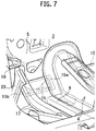
Fig. 7] Fig. 7 is a perspective view showing that the second vehicle body front section reinforcing member is coupled to a vehicle interior on-floor member provided in an interior. - [
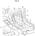
Fig. 8] Fig. 8 is an enlarged perspective view of a third vehicle body front section reinforcing member. - [
Fig. 9] Fig. 9 is an enlarged perspective view of a fourth vehicle body front section reinforcing member. - Hereinafter, a specific embodiment to which the present invention has been applied will be explained in detail with reference to drawings.
-
Fig. 1 is a perspective view showing structures of a front section and a lower section seen from an outside of a vehicle in a vehicle body front section structure seen from the outside of the vehicle (a perspective view in a case of looking up at a vehicle lower section from a position of a vehicle front lower part).Fig. 2 is a perspective view showing a structure in a vehicle interior of the vehicle body front section structure (a perspective view in a case of looking into an inside of the vehicle interior from a position of a side surface of the vehicle). Note that inFigs. 1 and2 , an arrow FR indicates a vehicle front, an arrow RR a vehicle rear, an arrow H a vehicle height, and an arrow W a vehicle width direction, respectively. - A
floor tunnel 4 is formed on anunderfloor 2 of avehicle body 1 so as to project into avehicle interior 3. Thefloor tunnel 4 is continuously formed on a center in the vehicle width direction W along a vehicle longitudinal direction from a portion where adash panel 5 and afloor panel 6 cross with each other to the vehicle rear RR. A front endridge line part 1a is located at the portion where thedash panel 5 and thefloor panel 6 cross with each other, and thedash panel 5 and thefloor panel 6 are coupled to each other by the front endridge line part 1a. Four reinforcing members (first to fourth vehicle body front section reinforcing members) for reinforcing strength in a front end portion of thefloor tunnel 4 are provided in thisvehicle body 1, and these four reinforcing members constitute a part of the vehicle body front section structure. - First, a U-shaped
member 8, which is the first vehicle body front section reinforcing member included in the vehicle body front section structure, is attached to a front end part of the floor tunnel in a vehicle front FR direction of thefloor tunnel 4 from the outside of the vehicle as shown inFig. 1 . The U-shapedmember 8 is attached so as to cover the front endridge line part 1a from the outside of the vehicle. The U-shapedmember 8 covers a whole of a front endridge line part 1a from an end of the vehicle upper end side of the front endridge line part 1a towardroots 7a of a pair offloor tunnel members 7 provided in the vehicle longitudinal direction. The pair offloor tunnel members 7 couple thefloor tunnel 4 to thefloor panel 6. - As shown in
Fig. 3 , a whole shape of the U-shapedmember 8 is an inverted U-shape that opens to a vehicle lower part, and the U-shapedmember 8 has aU-shaped part 8a, a pair of extendedparts 8b, and a pair of floor tunnelmember connecting parts 8c. The U-shapedpart 8a is formed in conformity with a U-shape of thefloor tunnel 4, and the pair of extendedparts 8b extend from a front end of the U-shapedpart 8a, i.e., an end of the vehicle upper end side of the U-shapedpart 8a, to the pair offloor tunnel members 7. The floor tunnelmember connecting part 8c is provided at a front end of the each extendedpart 8b. The U-shapedpart 8a, the pair of extendedparts 8b, and the pair of floor tunnelmember connecting parts 8c are integrally formed by press-molding of a steel plate, and they integrally constitute the U-shapedmember 8. - As shown in
Fig. 3 , a connecting part to thevehicle body 1 of the U-shapedmember 8 includes three parts of an outer periphery, an inner periphery, and ends. - A
flange 9 integrally formed therein that continues the U-shapedpart 8a, the pair of extendedparts 8b, and the pair of floor tunnelmember connecting parts 8c are integrally formed at the U-shapedmember 8. Theflange 9 corresponds to the outer periphery of the connecting part to thevehicle body 1 of the U-shapedmember 8. As shown inFigs. 4 and5 , the outer periphery of the U-shapedmember 8 is divided into a portion where three of thedash panel 5, a floor tunnelfront end panel 10, and theflange 9 are stacked and connected, and a portion where two of afront floor panel 11 and theflange 9 are stacked and connected. - In addition, a
bent part 13 made into a shape conforming to a front endside surface part 12 of thefloor tunnel 4 is integrally formed at the U-shapedmember 8. Thebent part 13 corresponds to the inner periphery of the connecting part to thevehicle body 1 of the U-shapedmember 8. Thebent part 13 is spot-welded and connected to the above-mentioned frontend side surface 12 of thefloor tunnel 4. - In addition, the pair of floor tunnel
member connecting parts 8c are integrally formed at the U-shapedmember 8. The pair of floor tunnelmember connecting parts 8c correspond to the ends of the connecting part to thevehicle body 1 of the U-shapedmember 8. The floor tunnelmember connecting parts 8c are spot-welded and connected to theroots 7a, which are front end parts of thefloor tunnel members 7. The floor tunnelmember connecting parts 8c are connected so as to cover theroots 7a of thefloor tunnel members 7. - The U-shaped
member 8 connected to thevehicle body 1 as described above covers the front endridge line part 1a in conformity with a shape of the front end part of the floor tunnel, and the U-shapedmember 8 also has a structure directly coupled to thefloor tunnel members 7. - A pair of dash
lower cross members 15, which are the second vehicle body front section reinforcing member, couple the U-shapedmember 8 tolower end roots 14a of a pair offront side members 14 provided in the vehicle longitudinal direction as shown inFigs. 1 ,6 and7 . Further, the pair of dashlower cross members 15 are fixed also to thedash panel 5. -
Flanges 16 are formed on whole outer peripheries of the dashlower cross members 15, theflanges 16 are spot-welded, and thereby the dashlower cross members 15 are connected to the U-shapedmember 8, thelower end roots 14a of thefront side members 14, and thedash panel 5. Namely, the dashlower cross members 15 are connected to thevehicle body 1 through theflanges 16 of the dashlower cross members 15. - One
ends 15a of the dashlower cross members 15 having a rectangular shape in a plane view (ends of theflanges 16 located on the near side of the floor tunnel 4) are spot-welded and connected to the extendedparts 8b of the U-shapedmember 8. In addition, theother ends 15b of the dash lower cross members 15 (ends of theflanges 16 located on the far side of the floor tunnel 4) are spot-welded and connected to theroots 14a of thefront side members 14. The other ends 15b of the dashlower cross members 15 are connected also to vehicle interior on-floor members 17 provided in accordance with theroots 14a of thefront side members 14 as shown inFigs. 6 and7 . Additionally, portions excluding the one ends 15a and the other ends 15b of theflanges 16 of the dashlower cross members 15 are spot-welded and connected to thedash panel 5. - A pair of upper
dash cross members 19, which are the third vehicle body front section reinforcing member, continuously couple vicinities of thelower end roots 14a of the pair offront side members 14 to a pair ofdash side panels 18 as shown inFigs. 2 and8 . - The upper
dash cross members 19 each have abody 20 having a cross-section of substantially trapezoidal shape, and aflange 21 formed on an outer periphery of thebody 20. One ends 19a of the upperdash cross members 19 each having a rectangular shape in a plane view (ends of theflanges 21 located on the near sides of the floor tunnel 4) are spot-welded and connected to thedash panel 5 near thelower end roots 14a of thefront side members 14. In addition, other ends 19b of the upper dash cross members 19 (ends of theflanges 21 located on the far sides of the floor tunnel 4) are spot-welded and connected to thedash side panels 18. Additionally, portions excluding the one ends 19a and the other ends 19b of theflanges 21 of the upperdash cross members 19 are spot-welded and connected towheel house panels 22. - Note that the upper
dash cross members 19 may be provided on the outside of the vehicle, and that the one ends 19a of the upperdash cross members 19 may be connected to the dashlower cross members 15. - A pair of lower
dash cross members 25, which are the fourth vehicle body front section reinforcing member, continuously couple thelower end roots 14a of the pair offront side members 14 to vehiclefront end parts 23a of a pair ofside sills 23 as shown inFigs. 2 and9 . - The lower
dash cross members 25 each have abody 26 having a rectangular shape in a plane view, and aflange 27 formed on an outer periphery of thebody 26. One ends 25a of the lower dash cross members 25 (ends of theflanges 27 located on the near sides of the floor tunnel 4) are spot-welded and connected to thefront end parts 17a of the vehicle interior on-floor members 17 provided in accordance with thelower end roots 14a of thefront side members 14. In addition, the other ends 25b of the lower dash cross members 25 (ends of theflanges 27 located on the far sides of the floor tunnel 4) are spot-welded and connected to the vehiclefront end parts 23a of theside sills 23. Additionally, portions excluding the one ends 25a and the other ends 25b of theflanges 27 of the lowerdash cross members 25 are spot-welded and connected to thewheel house panels 22. - Note that the lower
dash cross members 25 may be provided on the outside of the vehicle, and that the one ends 25a of the lowerdash cross members 25 may be connected to the dashlower cross members 15. - The outside of the vehicle of the vehicle body front section structure including the first to fourth vehicle body front section reinforcing members mentioned above is configured so that the
U-shaped member 8 covers a whole of a floor tunnel front end part and is connected to thefloor tunnel members 7, and so that the dashlower cross members 15 are connected to theU-shaped member 8 and theroots 14a of thefront side members 14. For this reason, the vehicle body front section structure is configured so that theU-shaped member 8 is connected to frame members which are thefloor tunnel members 7, and so that the dashlower cross members 15 are connected to frame members which are thefront side members 14. - In addition, an inside of the vehicle interior of the vehicle body front section structure including the first to fourth vehicle body front section reinforcing members has a structure that the upper
dash cross members 19 are connected to the frame members which are thefront side members 14 and also to thedash side panels 18, and that the lowerdash cross members 25 are connected to frame members which are the vehicle interior on-floor members 17 and theside sills 23. - According to the vehicle body front section structure of the present embodiment, since the
U-shaped member 8 which is the first vehicle body front section reinforcing member directly covers the whole of a floor tunnel front end part, strength at the front end of thefloor tunnel 4 can be improved. As a result, vehicle body deformation can be suppressed, and sound vibration performance can be improved. - Namely, according to the vehicle body front section structure of the present embodiment, since the first vehicle body front section reinforcing member enhances rigidity of the floor tunnel front end part, shear and a torsional stress due to crushing deformation of the floor tunnel front end part can be directly suppressed. As a result, the vehicle body deformation is suppressed, and the sound vibration performance is improved.
- In addition, since the
U-shaped member 8 is connected to frame members which are thefloor tunnel members 7, thefloor tunnel members 7 can be used as a part of a frame structure, and an external force input to thevehicle body 1 can be stress dispersed to thefloor tunnel members 7. Hereby, a shear stress and a torsional input which cause crushing deformation in which the floor tunnel front end part collapses in a lateral direction in a frequency range of 100 to 200 Hz of road noise, engine booming noise, etc. are dispersed to thefloor tunnel members 7 via theU-shaped member 8, and as a result, crushing deformation occurring at the floor tunnel front end part can be suppressed. - In addition, according to the vehicle body front section structure of the present embodiment, since the dash
lower cross members 15, which are the second vehicle body front section reinforcing members, are connected to the frame members which are thefront side members 14, thefront side members 14 can be used as a part of the frame structure, and an external force generated in thefloor tunnel 4 can be stress dispersed to thefront side members 14. In addition, since the dashlower cross members 15 are connected to theU-shaped member 8, strength of the floor tunnel front end part is improved by these dashlower cross members 15 andU-shaped member 8. In addition, since the dashlower cross members 15 are connected to the lowerdash cross members 25 through the vehicle interior on-floor members 17 so as to stress disperse to those members. - In addition, according to the vehicle body front section structure of the present embodiment, since the upper
dash cross members 19, which are the third vehicle body front section reinforcing members, are coupled to the vicinities of thelower end roots 14a of thefront side members 14, thefront side members 14 can be used as the part of the frame structure, and an external force input to the vehicle body can be stress dispersed to thefront side members 14. In addition, since the upperdash cross members 19 are coupled to thedash side panels 18, the external force generated in thefloor tunnel 4 can be dispersed to thedash side panels 18. - In addition, according to the vehicle body front section structure of the present embodiment, since the lower
dash cross members 25, which are the fourth vehicle body front section reinforcing members, are connected to thelower end roots 14a of thefront side members 14, thefront side members 14 can be used as the part of the frame structure, and the external force generated in thefloor tunnel 4 can be stress dispersed to thefront side members 14. In addition, since the lowerdash cross members 25 are connected to theside sills 23, the external force generated in thefloor tunnel 4 can be dispersed to theside sills 23 through the lowerdash cross members 25. - In addition, since the lower
dash cross members 25 are coupled to the vehicle interior on-floor members 17 provided in accordance with thelower end roots 14a of thefront side members 14, the vehicle interior on-floor members 17 can be used as a part of the frame structure, and the external force generated in thefloor tunnel 4 can be stress dispersed to the vehicle interior on-floor members 17. - By the above-mentioned stress dispersion, the external force input to the
vehicle body 1 is dispersed to the whole of a frame structure included in the vehicle body, and the external force that was input does not concentrate on specific portion. Particularly, the force generated in thefloor tunnel 4 is dispersed, and such crushing deformation that the floor tunnel front end part and thefloor tunnel 4 collapse in the lateral direction can be suppressed. Since a deformation mode of the frame structure accompanied by a change in volume of air in the vehicle interior is suppressed, increase of a noise level in the vehicle interior can be effectively suppressed. - Hereinbefore, although the embodiment of the present invention has been explained, the embodiment is merely an exemplification described in order to facilitate understanding of the present invention, and the present invention is not limited to the embodiment. A technical scope of the present invention is not limited to specific technical matters disclosed in the above-described embodiment, and various deformations, changes, alternative technologies, etc. that can be easily derived from the technical matters are also included, bearing in mind that the scope of protection is defined by the appended claims.
- This application claims priority based on Japanese Patent Application No.
2013-138613 filed on July 2, 2013 - The present invention can be utilized for a vehicle having a floor tunnel.
-
- 1 vehicle
- 2 underfloor
- 4 floor tunnel
- 5 dash panel
- 6 floor panel
- 7 floor tunnel member
- 8 U-shaped member (first vehicle body front section reinforcing member)
- 14 front side member
- 15 dash lower cross member (second vehicle body front section reinforcing member)
- 17 vehicle interior on-floor member
- 18 dash side panel
- 19 upper dash cross member (third vehicle body front section reinforcing member)
- 22 wheel house panel
- 23 side sill
- 25 lower dash cross member (fourth vehicle body front section reinforcing member)
Claims (5)
- A vehicle body front section structure,wherein a floor tunnel (4) projecting into a vehicle interior (3) on an underfloor (2) of the vehicle (1) is formed in a vehicle longitudinal direction, characterized in that,a first vehicle body front section reinforcing member (8) covers, from an outside of the vehicle (1), a whole of a floor tunnel front end part being a vehicle front of the floor tunnel (4), from a vehicle upper end to a root of each floor tunnel member (7) provided in the vehicle longitudinal direction along a front end ridge line part (1a),a lower end root (14a) of each front side member (14) is connected to a dash panel (5), andthe each front side member (14) extends forward from the lower end root (14a), andwherein a second vehicle body front section reinforcing member (15) couples the first vehicle body front section reinforcing member (8) to the lower end root (14a) of the front side member (14).
- The vehicle body front section structure according to claim 1,
wherein the first vehicle body front section reinforcing member (8) is connected to the floor tunnel member (7). - The vehicle body front section structure according to claim 1 or 2,
wherein a third vehicle body front section reinforcing member (19) is provided that continuously couples a vicinity of the lower end root (14a) of the each front side member (14) to a dash side panel part. - The vehicle body front section structure according to any one of claims 1 to 3,
wherein a fourth vehicle body front section reinforcing member (25) is provided that continuously couples the lower end root (14a) of the each front side member (14) to a vehicle front end part (23a) of a side sill (23). - The vehicle body front section structure according to any one of claims 1 to 3,
wherein a fourth vehicle body front section reinforcing member (25) is provided that continuously couples a vehicle interior on-floor member (17) provided in accordance with the lower end root (14a) of the each front side member (14) to a vehicle front end part (23a) of a side sill (23).
Applications Claiming Priority (2)
| Application Number | Priority Date | Filing Date | Title |
|---|---|---|---|
| JP2013138613 | 2013-07-02 | ||
| PCT/JP2014/066288 WO2015001973A1 (en) | 2013-07-02 | 2014-06-19 | Vehicle body front section structure |
Publications (3)
| Publication Number | Publication Date |
|---|---|
| EP3018041A1 EP3018041A1 (en) | 2016-05-11 |
| EP3018041A4 EP3018041A4 (en) | 2017-06-07 |
| EP3018041B1 true EP3018041B1 (en) | 2018-05-02 |
Family
ID=52143551
Family Applications (1)
| Application Number | Title | Priority Date | Filing Date |
|---|---|---|---|
| EP14818852.7A Active EP3018041B1 (en) | 2013-07-02 | 2014-06-19 | Vehicle body front section structure |
Country Status (9)
| Country | Link |
|---|---|
| US (1) | US9643659B2 (en) |
| EP (1) | EP3018041B1 (en) |
| JP (1) | JP6041054B2 (en) |
| CN (1) | CN105517882B (en) |
| BR (1) | BR112015032835B1 (en) |
| MX (1) | MX345882B (en) |
| MY (1) | MY161701A (en) |
| RU (1) | RU2615237C1 (en) |
| WO (1) | WO2015001973A1 (en) |
Families Citing this family (24)
| Publication number | Priority date | Publication date | Assignee | Title |
|---|---|---|---|---|
| CA2766258C (en) * | 2009-06-23 | 2019-01-29 | Atomic Energy Of Canada Limited (Aecl) | Circumferential sampling tool |
| JP6522982B2 (en) * | 2015-02-18 | 2019-05-29 | 本田技研工業株式会社 | Body structure |
| WO2016148057A1 (en) * | 2015-03-17 | 2016-09-22 | 本田技研工業株式会社 | Vehicle body structure |
| JP2017024698A (en) * | 2015-07-15 | 2017-02-02 | 現代自動車株式会社Hyundai Motor Company | Vehicle body coupling structure |
| KR101786665B1 (en) * | 2015-12-08 | 2017-10-19 | 현대자동차 주식회사 | Reinforcement structure of rear floor for automobile |
| KR101816378B1 (en) * | 2016-01-29 | 2018-01-08 | 현대자동차주식회사 | A structure of panel assembly for preventing column dive |
| CN105667604A (en) * | 2016-03-31 | 2016-06-15 | 上海长安汽车工程技术有限公司 | Reinforcement structure for front wall panel and front floor of automobile |
| CN105946981B (en) * | 2016-06-14 | 2018-05-04 | 重庆长安汽车股份有限公司 | It is a kind of to penetrate through front panel and the reinforcement structure on preceding floor |
| JP6547772B2 (en) * | 2017-01-24 | 2019-07-24 | トヨタ自動車株式会社 | Vehicle floor structure |
| KR102354133B1 (en) * | 2017-07-12 | 2022-01-24 | 현대자동차주식회사 | Support structure of dash panel for vehicle |
| JP6532513B2 (en) * | 2017-09-15 | 2019-06-19 | 本田技研工業株式会社 | Body structure |
| KR102383247B1 (en) * | 2017-10-11 | 2022-04-05 | 현대자동차 주식회사 | Front vehicle body reinforcing structure |
| KR102440606B1 (en) * | 2017-12-15 | 2022-09-05 | 현대자동차 주식회사 | Front vehicle body reinforcing structure |
| JP6881325B2 (en) * | 2018-01-16 | 2021-06-02 | マツダ株式会社 | Lower body structure |
| CN108454705A (en) * | 2018-03-26 | 2018-08-28 | 力帆实业(集团)股份有限公司 | Automobile dash board assembly |
| JP6881397B2 (en) * | 2018-06-15 | 2021-06-02 | マツダ株式会社 | Lower body structure |
| JP6881404B2 (en) * | 2018-08-13 | 2021-06-02 | マツダ株式会社 | Lower body structure |
| CN110857121B (en) * | 2018-08-23 | 2021-11-12 | 比亚迪股份有限公司 | Front collision force transmission mechanism and vehicle with same |
| WO2020217085A1 (en) * | 2019-04-23 | 2020-10-29 | Arcelormittal | Tunnel having integrated lateral reinforcements |
| JP7243438B2 (en) * | 2019-05-22 | 2023-03-22 | トヨタ自動車株式会社 | vehicle front structure |
| JP7247853B2 (en) * | 2019-10-16 | 2023-03-29 | マツダ株式会社 | car body structure |
| CN115107881B (en) * | 2021-03-18 | 2024-09-03 | 本田技研工业株式会社 | Vehicle body panel structure |
| JP7487705B2 (en) * | 2021-04-30 | 2024-05-21 | トヨタ自動車株式会社 | Floor Structure |
| DE102023201286A1 (en) * | 2023-02-15 | 2024-08-22 | Volkswagen Aktiengesellschaft | Method for producing a body unit and vehicle |
Family Cites Families (17)
| Publication number | Priority date | Publication date | Assignee | Title |
|---|---|---|---|---|
| JPH018462Y2 (en) * | 1984-10-16 | 1989-03-07 | ||
| JPS62181976A (en) | 1986-02-06 | 1987-08-10 | Mazda Motor Corp | Structure of lower body by vehicle |
| JPH0625414Y2 (en) * | 1987-09-29 | 1994-07-06 | 三菱自動車工業株式会社 | Front body joint structure for automobile |
| JP2936877B2 (en) * | 1992-03-25 | 1999-08-23 | トヨタ自動車株式会社 | Car body front structure |
| DE10232841A1 (en) | 2002-07-19 | 2004-02-05 | Volkswagen Ag | Floor support arrangement on motor vehicles |
| JP4483592B2 (en) * | 2005-01-14 | 2010-06-16 | トヨタ自動車株式会社 | Dash panel reinforcement structure |
| TWI361766B (en) * | 2007-07-12 | 2012-04-11 | Honda Motor Co Ltd | Vehicle body frame structure |
| JP2009248593A (en) | 2008-04-01 | 2009-10-29 | Toyota Motor Corp | Vehicle body framework structure |
| CN201405934Y (en) * | 2009-03-12 | 2010-02-17 | 中通客车控股股份有限公司 | Bus full-bearing body with large-scale rectangular tube chassis |
| US8292356B2 (en) * | 2009-03-17 | 2012-10-23 | Mazda Motor Corporation | Lower vehicle-body structure of vehicle |
| JP5510778B2 (en) | 2009-05-15 | 2014-06-04 | スズキ株式会社 | Body structure around the dash panel |
| WO2011055695A1 (en) * | 2009-11-05 | 2011-05-12 | 本田技研工業株式会社 | Vehicle body structure |
| DE102009056840A1 (en) * | 2009-12-03 | 2011-06-09 | GM Global Technology Operations LLC, ( n. d. Ges. d. Staates Delaware ), Detroit | Substructure structure of a motor vehicle body |
| US8702158B2 (en) * | 2010-05-25 | 2014-04-22 | Honda Motor Co., Ltd. | Structure for vehicle body front portion |
| WO2012102067A1 (en) * | 2011-01-26 | 2012-08-02 | 本田技研工業株式会社 | Structure for front of vehicle body |
| CN102938450B (en) * | 2011-08-16 | 2015-11-25 | 上海通用汽车有限公司 | Vehicle battery box, bodywork component and automobile |
| JP5738163B2 (en) * | 2011-12-15 | 2015-06-17 | 本田技研工業株式会社 | Body structure |
-
2014
- 2014-06-19 WO PCT/JP2014/066288 patent/WO2015001973A1/en active Application Filing
- 2014-06-19 MY MYPI2015704700A patent/MY161701A/en unknown
- 2014-06-19 MX MX2015017584A patent/MX345882B/en active IP Right Grant
- 2014-06-19 EP EP14818852.7A patent/EP3018041B1/en active Active
- 2014-06-19 RU RU2016103130A patent/RU2615237C1/en active
- 2014-06-19 US US14/902,474 patent/US9643659B2/en active Active
- 2014-06-19 JP JP2015525138A patent/JP6041054B2/en active Active
- 2014-06-19 BR BR112015032835-0A patent/BR112015032835B1/en active IP Right Grant
- 2014-06-19 CN CN201480048414.XA patent/CN105517882B/en active Active
Non-Patent Citations (1)
| Title |
|---|
| None * |
Also Published As
| Publication number | Publication date |
|---|---|
| BR112015032835A2 (en) | 2020-04-28 |
| US20170001669A1 (en) | 2017-01-05 |
| MY161701A (en) | 2017-05-15 |
| MX2015017584A (en) | 2016-04-07 |
| WO2015001973A1 (en) | 2015-01-08 |
| BR112015032835B1 (en) | 2022-04-19 |
| CN105517882B (en) | 2017-04-12 |
| JP6041054B2 (en) | 2016-12-07 |
| EP3018041A1 (en) | 2016-05-11 |
| EP3018041A4 (en) | 2017-06-07 |
| US9643659B2 (en) | 2017-05-09 |
| JPWO2015001973A1 (en) | 2017-02-23 |
| CN105517882A (en) | 2016-04-20 |
| RU2615237C1 (en) | 2017-04-04 |
| MX345882B (en) | 2017-02-22 |
Similar Documents
| Publication | Publication Date | Title |
|---|---|---|
| EP3018041B1 (en) | Vehicle body front section structure | |
| CN110352157B (en) | Lower body structure of vehicle | |
| EP3063052B1 (en) | Suspension tower and vehicle front structure | |
| JP6052408B2 (en) | Body front structure | |
| EP3042832A1 (en) | Vehicle body structure | |
| JP6511078B2 (en) | Electric car floor structure | |
| JP6557290B2 (en) | Body front structure | |
| WO2012121142A1 (en) | Rear structure of car body | |
| JP2008174181A (en) | Vehicle body lower part structure | |
| JP6584457B2 (en) | Body front structure | |
| JP2016002871A (en) | Vehicle front part structure | |
| JP2019171934A (en) | Front body structure of vehicle | |
| JP6181099B2 (en) | Rear structure of the car body | |
| JP2019171932A (en) | Front part vehicle body structure of vehicle | |
| JP2019171931A (en) | Front part vehicle body structure of vehicle | |
| JP2017039352A (en) | Vehicle front part structure | |
| US20180170440A1 (en) | Vehicle body front structure | |
| JP5825220B2 (en) | Body front structure | |
| JP6717027B2 (en) | Front structure of car body | |
| WO2014199755A1 (en) | Vehicle side structure | |
| JP2009280106A (en) | Vehicle frame structure | |
| JP5234324B2 (en) | Vehicle body structure | |
| JP2023046924A (en) | Vehicle body lower part structure | |
| EP3702249A1 (en) | Vehicle body structure and method of producing the same | |
| JP6525243B2 (en) | High roof mounting structure of vehicle |
Legal Events
| Date | Code | Title | Description |
|---|---|---|---|
| PUAI | Public reference made under article 153(3) epc to a published international application that has entered the european phase |
Free format text: ORIGINAL CODE: 0009012 |
|
| 17P | Request for examination filed |
Effective date: 20160129 |
|
| AK | Designated contracting states |
Kind code of ref document: A1 Designated state(s): AL AT BE BG CH CY CZ DE DK EE ES FI FR GB GR HR HU IE IS IT LI LT LU LV MC MK MT NL NO PL PT RO RS SE SI SK SM TR |
|
| AX | Request for extension of the european patent |
Extension state: BA ME |
|
| DAX | Request for extension of the european patent (deleted) | ||
| A4 | Supplementary search report drawn up and despatched |
Effective date: 20170509 |
|
| RIC1 | Information provided on ipc code assigned before grant |
Ipc: B62D 25/20 20060101AFI20170502BHEP Ipc: B62D 25/14 20060101ALI20170502BHEP Ipc: B62D 25/08 20060101ALI20170502BHEP |
|
| GRAP | Despatch of communication of intention to grant a patent |
Free format text: ORIGINAL CODE: EPIDOSNIGR1 |
|
| STAA | Information on the status of an ep patent application or granted ep patent |
Free format text: STATUS: GRANT OF PATENT IS INTENDED |
|
| INTG | Intention to grant announced |
Effective date: 20180207 |
|
| RIN1 | Information on inventor provided before grant (corrected) |
Inventor name: MORITA, YUKIO Inventor name: KANEDA, TOMOYUKI Inventor name: OHIGASHI, AKIRA |
|
| GRAS | Grant fee paid |
Free format text: ORIGINAL CODE: EPIDOSNIGR3 |
|
| GRAA | (expected) grant |
Free format text: ORIGINAL CODE: 0009210 |
|
| STAA | Information on the status of an ep patent application or granted ep patent |
Free format text: STATUS: THE PATENT HAS BEEN GRANTED |
|
| AK | Designated contracting states |
Kind code of ref document: B1 Designated state(s): AL AT BE BG CH CY CZ DE DK EE ES FI FR GB GR HR HU IE IS IT LI LT LU LV MC MK MT NL NO PL PT RO RS SE SI SK SM TR |
|
| REG | Reference to a national code |
Ref country code: GB Ref legal event code: FG4D |
|
| REG | Reference to a national code |
Ref country code: CH Ref legal event code: EP Ref country code: AT Ref legal event code: REF Ref document number: 994906 Country of ref document: AT Kind code of ref document: T Effective date: 20180515 |
|
| REG | Reference to a national code |
Ref country code: DE Ref legal event code: R096 Ref document number: 602014025000 Country of ref document: DE Ref country code: IE Ref legal event code: FG4D |
|
| REG | Reference to a national code |
Ref country code: FR Ref legal event code: PLFP Year of fee payment: 5 |
|
| REG | Reference to a national code |
Ref country code: NL Ref legal event code: MP Effective date: 20180502 |
|
| REG | Reference to a national code |
Ref country code: LT Ref legal event code: MG4D |
|
| PG25 | Lapsed in a contracting state [announced via postgrant information from national office to epo] |
Ref country code: LT Free format text: LAPSE BECAUSE OF FAILURE TO SUBMIT A TRANSLATION OF THE DESCRIPTION OR TO PAY THE FEE WITHIN THE PRESCRIBED TIME-LIMIT Effective date: 20180502 Ref country code: NO Free format text: LAPSE BECAUSE OF FAILURE TO SUBMIT A TRANSLATION OF THE DESCRIPTION OR TO PAY THE FEE WITHIN THE PRESCRIBED TIME-LIMIT Effective date: 20180802 Ref country code: BG Free format text: LAPSE BECAUSE OF FAILURE TO SUBMIT A TRANSLATION OF THE DESCRIPTION OR TO PAY THE FEE WITHIN THE PRESCRIBED TIME-LIMIT Effective date: 20180802 Ref country code: SE Free format text: LAPSE BECAUSE OF FAILURE TO SUBMIT A TRANSLATION OF THE DESCRIPTION OR TO PAY THE FEE WITHIN THE PRESCRIBED TIME-LIMIT Effective date: 20180502 Ref country code: FI Free format text: LAPSE BECAUSE OF FAILURE TO SUBMIT A TRANSLATION OF THE DESCRIPTION OR TO PAY THE FEE WITHIN THE PRESCRIBED TIME-LIMIT Effective date: 20180502 Ref country code: ES Free format text: LAPSE BECAUSE OF FAILURE TO SUBMIT A TRANSLATION OF THE DESCRIPTION OR TO PAY THE FEE WITHIN THE PRESCRIBED TIME-LIMIT Effective date: 20180502 |
|
| PG25 | Lapsed in a contracting state [announced via postgrant information from national office to epo] |
Ref country code: NL Free format text: LAPSE BECAUSE OF FAILURE TO SUBMIT A TRANSLATION OF THE DESCRIPTION OR TO PAY THE FEE WITHIN THE PRESCRIBED TIME-LIMIT Effective date: 20180502 Ref country code: HR Free format text: LAPSE BECAUSE OF FAILURE TO SUBMIT A TRANSLATION OF THE DESCRIPTION OR TO PAY THE FEE WITHIN THE PRESCRIBED TIME-LIMIT Effective date: 20180502 Ref country code: GR Free format text: LAPSE BECAUSE OF FAILURE TO SUBMIT A TRANSLATION OF THE DESCRIPTION OR TO PAY THE FEE WITHIN THE PRESCRIBED TIME-LIMIT Effective date: 20180803 Ref country code: LV Free format text: LAPSE BECAUSE OF FAILURE TO SUBMIT A TRANSLATION OF THE DESCRIPTION OR TO PAY THE FEE WITHIN THE PRESCRIBED TIME-LIMIT Effective date: 20180502 Ref country code: RS Free format text: LAPSE BECAUSE OF FAILURE TO SUBMIT A TRANSLATION OF THE DESCRIPTION OR TO PAY THE FEE WITHIN THE PRESCRIBED TIME-LIMIT Effective date: 20180502 |
|
| REG | Reference to a national code |
Ref country code: AT Ref legal event code: MK05 Ref document number: 994906 Country of ref document: AT Kind code of ref document: T Effective date: 20180502 |
|
| PG25 | Lapsed in a contracting state [announced via postgrant information from national office to epo] |
Ref country code: AT Free format text: LAPSE BECAUSE OF FAILURE TO SUBMIT A TRANSLATION OF THE DESCRIPTION OR TO PAY THE FEE WITHIN THE PRESCRIBED TIME-LIMIT Effective date: 20180502 Ref country code: DK Free format text: LAPSE BECAUSE OF FAILURE TO SUBMIT A TRANSLATION OF THE DESCRIPTION OR TO PAY THE FEE WITHIN THE PRESCRIBED TIME-LIMIT Effective date: 20180502 Ref country code: EE Free format text: LAPSE BECAUSE OF FAILURE TO SUBMIT A TRANSLATION OF THE DESCRIPTION OR TO PAY THE FEE WITHIN THE PRESCRIBED TIME-LIMIT Effective date: 20180502 Ref country code: CZ Free format text: LAPSE BECAUSE OF FAILURE TO SUBMIT A TRANSLATION OF THE DESCRIPTION OR TO PAY THE FEE WITHIN THE PRESCRIBED TIME-LIMIT Effective date: 20180502 Ref country code: RO Free format text: LAPSE BECAUSE OF FAILURE TO SUBMIT A TRANSLATION OF THE DESCRIPTION OR TO PAY THE FEE WITHIN THE PRESCRIBED TIME-LIMIT Effective date: 20180502 Ref country code: PL Free format text: LAPSE BECAUSE OF FAILURE TO SUBMIT A TRANSLATION OF THE DESCRIPTION OR TO PAY THE FEE WITHIN THE PRESCRIBED TIME-LIMIT Effective date: 20180502 Ref country code: SK Free format text: LAPSE BECAUSE OF FAILURE TO SUBMIT A TRANSLATION OF THE DESCRIPTION OR TO PAY THE FEE WITHIN THE PRESCRIBED TIME-LIMIT Effective date: 20180502 |
|
| REG | Reference to a national code |
Ref country code: CH Ref legal event code: PL |
|
| REG | Reference to a national code |
Ref country code: DE Ref legal event code: R097 Ref document number: 602014025000 Country of ref document: DE |
|
| PG25 | Lapsed in a contracting state [announced via postgrant information from national office to epo] |
Ref country code: SM Free format text: LAPSE BECAUSE OF FAILURE TO SUBMIT A TRANSLATION OF THE DESCRIPTION OR TO PAY THE FEE WITHIN THE PRESCRIBED TIME-LIMIT Effective date: 20180502 Ref country code: IT Free format text: LAPSE BECAUSE OF FAILURE TO SUBMIT A TRANSLATION OF THE DESCRIPTION OR TO PAY THE FEE WITHIN THE PRESCRIBED TIME-LIMIT Effective date: 20180502 |
|
| REG | Reference to a national code |
Ref country code: BE Ref legal event code: MM Effective date: 20180630 |
|
| PLBE | No opposition filed within time limit |
Free format text: ORIGINAL CODE: 0009261 |
|
| STAA | Information on the status of an ep patent application or granted ep patent |
Free format text: STATUS: NO OPPOSITION FILED WITHIN TIME LIMIT |
|
| REG | Reference to a national code |
Ref country code: IE Ref legal event code: MM4A |
|
| PG25 | Lapsed in a contracting state [announced via postgrant information from national office to epo] |
Ref country code: MC Free format text: LAPSE BECAUSE OF FAILURE TO SUBMIT A TRANSLATION OF THE DESCRIPTION OR TO PAY THE FEE WITHIN THE PRESCRIBED TIME-LIMIT Effective date: 20180502 Ref country code: LU Free format text: LAPSE BECAUSE OF NON-PAYMENT OF DUE FEES Effective date: 20180619 |
|
| 26N | No opposition filed |
Effective date: 20190205 |
|
| PG25 | Lapsed in a contracting state [announced via postgrant information from national office to epo] |
Ref country code: IE Free format text: LAPSE BECAUSE OF NON-PAYMENT OF DUE FEES Effective date: 20180619 Ref country code: LI Free format text: LAPSE BECAUSE OF NON-PAYMENT OF DUE FEES Effective date: 20180630 Ref country code: CH Free format text: LAPSE BECAUSE OF NON-PAYMENT OF DUE FEES Effective date: 20180630 |
|
| PG25 | Lapsed in a contracting state [announced via postgrant information from national office to epo] |
Ref country code: SI Free format text: LAPSE BECAUSE OF FAILURE TO SUBMIT A TRANSLATION OF THE DESCRIPTION OR TO PAY THE FEE WITHIN THE PRESCRIBED TIME-LIMIT Effective date: 20180502 Ref country code: BE Free format text: LAPSE BECAUSE OF NON-PAYMENT OF DUE FEES Effective date: 20180630 |
|
| PG25 | Lapsed in a contracting state [announced via postgrant information from national office to epo] |
Ref country code: AL Free format text: LAPSE BECAUSE OF FAILURE TO SUBMIT A TRANSLATION OF THE DESCRIPTION OR TO PAY THE FEE WITHIN THE PRESCRIBED TIME-LIMIT Effective date: 20180502 |
|
| PG25 | Lapsed in a contracting state [announced via postgrant information from national office to epo] |
Ref country code: MT Free format text: LAPSE BECAUSE OF NON-PAYMENT OF DUE FEES Effective date: 20180619 |
|
| PG25 | Lapsed in a contracting state [announced via postgrant information from national office to epo] |
Ref country code: TR Free format text: LAPSE BECAUSE OF FAILURE TO SUBMIT A TRANSLATION OF THE DESCRIPTION OR TO PAY THE FEE WITHIN THE PRESCRIBED TIME-LIMIT Effective date: 20180502 |
|
| PG25 | Lapsed in a contracting state [announced via postgrant information from national office to epo] |
Ref country code: PT Free format text: LAPSE BECAUSE OF FAILURE TO SUBMIT A TRANSLATION OF THE DESCRIPTION OR TO PAY THE FEE WITHIN THE PRESCRIBED TIME-LIMIT Effective date: 20180502 |
|
| PG25 | Lapsed in a contracting state [announced via postgrant information from national office to epo] |
Ref country code: HU Free format text: LAPSE BECAUSE OF FAILURE TO SUBMIT A TRANSLATION OF THE DESCRIPTION OR TO PAY THE FEE WITHIN THE PRESCRIBED TIME-LIMIT; INVALID AB INITIO Effective date: 20140619 Ref country code: CY Free format text: LAPSE BECAUSE OF FAILURE TO SUBMIT A TRANSLATION OF THE DESCRIPTION OR TO PAY THE FEE WITHIN THE PRESCRIBED TIME-LIMIT Effective date: 20180502 Ref country code: MK Free format text: LAPSE BECAUSE OF NON-PAYMENT OF DUE FEES Effective date: 20180502 |
|
| PG25 | Lapsed in a contracting state [announced via postgrant information from national office to epo] |
Ref country code: IS Free format text: LAPSE BECAUSE OF FAILURE TO SUBMIT A TRANSLATION OF THE DESCRIPTION OR TO PAY THE FEE WITHIN THE PRESCRIBED TIME-LIMIT Effective date: 20180902 |
|
| REG | Reference to a national code |
Ref country code: DE Ref legal event code: R084 Ref document number: 602014025000 Country of ref document: DE |
|
| REG | Reference to a national code |
Ref country code: GB Ref legal event code: 746 Effective date: 20230926 |
|
| PGFP | Annual fee paid to national office [announced via postgrant information from national office to epo] |
Ref country code: GB Payment date: 20240521 Year of fee payment: 11 |
|
| PGFP | Annual fee paid to national office [announced via postgrant information from national office to epo] |
Ref country code: DE Payment date: 20240521 Year of fee payment: 11 |
|
| PGFP | Annual fee paid to national office [announced via postgrant information from national office to epo] |
Ref country code: FR Payment date: 20240521 Year of fee payment: 11 |