JP6525243B2 - High roof mounting structure of vehicle - Google Patents
High roof mounting structure of vehicle Download PDFInfo
- Publication number
- JP6525243B2 JP6525243B2 JP2014256761A JP2014256761A JP6525243B2 JP 6525243 B2 JP6525243 B2 JP 6525243B2 JP 2014256761 A JP2014256761 A JP 2014256761A JP 2014256761 A JP2014256761 A JP 2014256761A JP 6525243 B2 JP6525243 B2 JP 6525243B2
- Authority
- JP
- Japan
- Prior art keywords
- reinforcement
- roof
- fixed
- vehicle
- receiving surface
- Prior art date
- Legal status (The legal status is an assumption and is not a legal conclusion. Google has not performed a legal analysis and makes no representation as to the accuracy of the status listed.)
- Active
Links
Images


Landscapes
- Body Structure For Vehicles (AREA)
Description
本発明は、車両のハイルーフ取付構造に関する。 The present invention relates to a high roof mounting structure of a vehicle.
特許文献1には、ハイルーフの側縁フランジを、車室のサイドレールに固着したドリップレールに接合固着するトラックのハイルーフ取付構造が記載されている。 Patent Document 1 describes a high roof mounting structure of a truck in which a side edge flange of a high roof is joined and fixed to a drip rail fixed to a side rail of a cabin.
車両事故等により車両が反転し、ルーフの天井面から車室側へ入力荷重が増大した際のルーフの上下方向の潰れを抑制するため、特許文献1のハイルーフ取付構造において、ルーフサイドパネルの内面に上下方向に延びるレインフォースを固定するとともに、ボディサイド(サイドレール)にブラケットを固着し、ブラケットとレインフォースを締結することにより、ブラケットを介してレインフォースをボディサイドに固定することが考えられる。これにより、天井面からの荷重をボディサイド側に伝達することができる。 In the high roof mounting structure of Patent Document 1, the inner surface of the roof side panel is designed to suppress collapse of the roof in the vertical direction when the input load is increased from the ceiling surface of the roof to the cabin side due to the vehicle reversing due to a vehicle accident or the like. It is possible to fix the reinforcement to the body side via the bracket by fixing the reinforcement extending vertically to the body and fixing the bracket to the body side (side rail) and fastening the bracket and the reinforcement. . Thereby, the load from the ceiling surface can be transmitted to the body side.
しかし、レインフォースをボディサイド側にブラケットを介して固定する構造では、ハイルーフの組付け誤差等からブラケットのボルト孔と相手側(例えばレインフォース)のボルト孔との位置ずれが生じ、ブラケットを取り付けることができない可能性がある。係る不都合は、剛性が低いブラケットを使用し、ブラケットを変形させて誤差を吸収することによって解消可能である。ところが、剛性が低いブラケットを使用すると、荷重の増大によってブラケットが破損し、レインフォースが有効に機能しない可能性がある。このように、ハイルーフの組付け作業性の向上と潰れ変形の抑制とを両立して図ることが難しい。 However, in a structure in which reinforcement is fixed to the body side via a bracket, the mounting error of the high roof causes misalignment between the bolt hole of the bracket and the other (for example, reinforcement) bolt hole. It may not be possible. Such a disadvantage can be eliminated by using a low-rigidity bracket and deforming the bracket to absorb errors. However, if a low rigidity bracket is used, the increase in load may damage the bracket and the reinforcement may not function effectively. As described above, it is difficult to achieve both the improvement of the assembling performance of the high roof and the suppression of the crushing deformation.
そこで、本発明は、組付け作業性の向上と潰れ変形の抑制とを両立して図ることが可能な車両のハイルーフ取付構造の提供を目的とする。 Then, an object of the present invention is to provide a high roof attachment structure of a vehicle that can achieve both improvement in assembling workability and suppression of crushing deformation.
上記目的を達成すべく、本発明の第1の態様の車両のハイルーフ取付構造は、天井面部と左右1対のルーフ側面部とを有する。天井面部は、車室の上方を区画する。左右1対のルーフ側面部は、天井面部の車幅方向両側縁から下方へ延びる。左右のルーフ側面部の下部は、車室の車幅方向両側の上部で前後方向に延びる左右1対のボディサイドに固定される。 In order to achieve the above object, a high roof mounting structure of a vehicle according to a first aspect of the present invention has a ceiling surface and a pair of left and right roof side surfaces. The ceiling surface section defines the upper side of the cabin. The pair of left and right roof side portions extend downward from both side edges in the vehicle width direction of the ceiling surface portion. Lower portions of the left and right roof side portions are fixed to a pair of left and right body sides extending in the front and rear direction at upper portions on both sides in the vehicle width direction of the cabin.
ルーフ側面部の内面には、ルーフ側面部との間に上下方向に延びる閉断面を形成するレインフォースが固着される。レインフォースは、ボディサイドには固定されず、ボディサイドには、鉛直方向と交叉し、レインフォースの端面と対向するレインフォース受面が設けられる。レインフォースの端面は、レインフォース受面に近接又は接触する。レインフォース受面は、上方へ突出して閉断面に収容されるレインフォース移動規制部を有する。レインフォース移動規制部は、レインフォースの端面がレインフォース受面に当接した際に、レインフォース受面上でのレインフォースの端面の移動を規制する。 On the inner surface of the roof side surface portion, a reinforcement is fixed which forms a closed cross section extending in the vertical direction between the roof side surface portion and the roof side surface portion. The reinforcement is not fixed to the body side, and the body side is provided with a reinforcement receiving surface which intersects the vertical direction and faces the end face of the reinforcement. The end face of the reinforcement approaches or contacts the reinforcement receiving surface. The reinforcement receiving surface has a reinforcement movement restricting portion which protrudes upward and is accommodated in the closed cross section. The reinforcement movement restricting part restricts the movement of the end surface of the reinforcement on the reinforcement receiving surface when the end surface of the reinforcement abuts on the reinforcement receiving surface.
上記構成では、車両事故等により車両が反転し、天井面部から車室側への入力荷重が増大した場合、レインフォースの端面がレインフォース受面に当接し、天井面部からの荷重がレインフォース受面を介してボディサイドに伝達される。従って、レインフォースを有効に機能させて、ハイルーフの潰れ変形を確実に抑制することができる。 In the above configuration, when the vehicle reverses due to a vehicle accident or the like and the input load from the ceiling surface to the compartment increases, the end face of the reinforcement contacts the reinforcement receiving surface, and the load from the ceiling surface receives the reinforcement It is transmitted to the body side through the face. Therefore, reinforcement can be made to function effectively, and crushing deformation of the high roof can be reliably suppressed.
また、ブラケット等を介してレインフォースをボディサイド側に固定しないので、ハイルーフの組付け作業性が向上する。 In addition, since the reinforcement is not fixed to the body side through the bracket or the like, the assembling performance of the high roof is improved.
また、レインフォース移動規制部によってレインフォースの倒れが防止されるので、天井面部からの荷重をさらに確実にボディサイドに伝達することができる。
Further , since the fall of the reinforcement is prevented by the reinforcement movement restricting portion, the load from the ceiling surface portion can be more reliably transmitted to the body side.
本発明の車両のハイルーフ取付構造によれば、組付け作業性の向上と潰れ変形の抑制とを両立して図ることができる。 According to the high roof mounting structure of a vehicle of the present invention, it is possible to achieve both improvement in assembling workability and suppression of crushing deformation.
以下、本発明の実施形態について図面を参照して詳細に説明する。本実施形態のハイルーフ取付構造1は、トラック等の車室(キャブ)2の上方に通常の高さ(標準車高)のルーフ(図示省略)に代えてハイルーフ3を取り付けるために用いられる。
Hereinafter, embodiments of the present invention will be described in detail with reference to the drawings. The high roof mounting structure 1 of the present embodiment is used to mount a
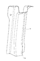
図1に示すように、車室2の車幅方向両側(左右両側)を形成する左右1対のボディサイド4は、車幅方向外側のサイドパネルアウタ5とサイドパネルインナ6とからそれぞれ構成される。サイドパネルアウタ5の上端部は、車幅方向内側に曲折してサイドパネルインナ6の上端部に固着され、サイドパネルインナ6との間に前後方向に延びる閉断面20を形成する。閉断面20の車幅方向外側を区画するサイドパネルアウタ5の上端外側面部24には、サイドパネルアウタ5の車幅方向外側で前後方向に延びるアウタレール7が固定される。
As shown in FIG. 1, a pair of left and
ハイルーフ3は、車室2の上方を区画する天井面部9と、天井面部9の車幅方向両側縁から下方へ曲折して延びる左右1対のルーフ側面部10とを有する。天井面部9の車幅方向外側の端縁部9aとルーフ側面部10の上端縁部10aとは、上下に重ねられて固着される。ルーフ側面部10の下端部には、車幅方向外側に曲折するレール当接部19が形成され、レール当接部19をアウタレール7に載置して固定することによって、ハイルーフ3がボディサイド4に固定され、ルーフ側面部10がボディサイド4(後述するボディサイド上面部25)から起立して延びる。なお、標準車高のルーフの場合は、ボディサイド上面部25に天井面部(図示省略)が固定される。
The
図3及び図4に示すように、天井面部9の内面(下面)における前側及び後側のそれぞれには、車幅方向に延びるレインフォース11が接着剤により固着される。前後(計2本)のレインフォース11の各々は、断面チャネル状に折曲形成された金属板製であり、天井面部9の内面との間に、車幅方向に延びる矩形状の閉断面(空間)21を形成する。
As shown in FIGS. 3 and 4,
各ルーフ側面部10の内面における前側及び後側のそれぞれには、上下方向に延びるレインフォース12が接着剤により固着される。前後左右(計4本)のレインフォース12の各々は、1部品で構成される。各レインフォース12は、断面チャネル状に折曲形成された金属板製であり、ルーフ側面部10の内面との間に、上下方向に延びる矩形状の閉断面(空間)22を形成する。各レインフォース12の上端部は、天井面部9の内面に固定される。
On each of the front and rear sides of the inner surface of each roof
天井面部9に固着されるレインフォース11と、ルーフ側面部10に固着されるレインフォース12との間には、レインフォース11,12同士を繋ぎ合わせる連結部材13が設けられる。前後左右(計4本)の連結部材13の各々は、断面チャネル状に折曲形成された金属板製であり、天井面部9とルーフ側面部10との接合部分において、天井面部9の内面及びルーフ側面部10の内面との間に、車幅方向に延びる矩形状の閉断面(空間)23を形成する。レインフォース11,12が形成する閉断面21,22は、連結部材13が形成する閉断面23を介して連続する。各連結部材13の車幅方向外側の端部は、ボルト14及びナット15によってレインフォース12に締結固定される。
Between the
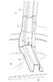
図1に示すように、閉断面20の上方を区画するサイドパネルアウタ5の上面部(ボディサイド上面部)25は、鉛直方向と交叉して前後方向に延びる。ハイルーフ3に固着されたレインフォース12の下方のボディサイド上面部25には、金属板製のレインフォース受部材8が固定される。ボディサイド上面部25に固定されたレインフォース受部材8の上面は、鉛直方向と交叉して、レインフォース12の下端面12aと対向するレインフォース受面8aを構成する。レインフォース受面8aには、レインフォース12(図2参照)の下端面12aが近接又は接触する。
As shown in FIG. 1, the upper surface portion (body-side upper surface portion) 25 of the side panel outer 5 partitioning the upper side of the closed
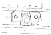
図5及び図6に示すように、レインフォース受部材8には、平板状の固定部16と、レインフォース受部材8の中間部分において固定部16から上方に突出(膨出)するレインフォース移動規制部17と、固定部16の車幅方向内側の端縁から上方へ曲折してレインフォース受部材8の剛性を高める周縁リブ26とが、プレス加工によって一体形成される。
As shown in FIGS. 5 and 6, in the
固定部16には、ボルト孔として丸孔16aと長孔16bとが形成される。レインフォース受部材8は、丸孔16aと長孔16bとの各々を挿通するボルト18によって、ボディサイド4のサイドパネルアウタ5に締結固定される。なお、ボルト孔の一方が長孔16bであるため、組付け誤差を吸収することができる。
レインフォース移動規制部17は、ハイルーフ3がボディサイド4に固定された状態で、レインフォース12とルーフ側面部10とが形成する閉空間22に収容され、レインフォース12の下端面12aがレインフォース受面8aに当接した際に、上下方向と交叉する方向(前後方向及び左右方向)へのレインフォース12の移動を規制する。
The reinforcement
本実施形態によれば、車両事故等により車両が反転し、天井面部9から車室2側への入力荷重が増大した場合、レインフォース12の下端面12aがレインフォース受面8aに当接し、天井面部9からの荷重がレインフォース受面8aを介してボディサイド4に伝達される。従って、レインフォース12を有効に機能させて、ハイルーフ3の潰れ変形を確実に抑制することができる。
According to the present embodiment, when the vehicle reverses due to a vehicle accident or the like and the input load from the ceiling surface 9 to the
また、ブラケット等を介してレインフォース12をボディサイド4側に固定しないので、ハイルーフ3の組付け作業性が向上する。
Further, since the
さらに、レインフォース移動規制部17によってレインフォース12の倒れが防止されるので、天井面部9からの荷重をさらに確実にボディサイド4に伝達することができる。
Furthermore, since the fall of the
以上、本発明者によってなされた発明を適用した実施形態について説明したが、この実施形態による本発明の開示の一部をなす論述及び図面により本発明は限定されることはない。すなわち、この実施形態に基づいて当業者等によりなされる他の実施形態、実施例及び運用技術等は全て本発明の範疇に含まれることは勿論であることを付け加えておく。 Although the embodiment to which the invention made by the inventor is applied has been described above, the present invention is not limited by the description and the drawings that form a part of the disclosure of the present invention according to this embodiment. That is, it is needless to say that it is needless to say that all other embodiments, examples, operation techniques and the like made by those skilled in the art based on this embodiment are included in the scope of the present invention.
例えば、本実施形態ではレインフォース受部材8をボディサイド上面部25に固定し、レインフォース受部材8の上面をレインフォース受面8aとしたが、レインフォース受部材8を省略し、ボディサイド上面部25の外面(上面)をレインフォース受面としてもよい。
For example, in the present embodiment, although the
本発明のハイルーフ取付構造は、トラックその他の車両に用いることができる。 The high roof mounting structure of the present invention can be used in trucks and other vehicles.
1 ハイルーフ取付構造
2 車室
3 ハイルーフ
4 ボディサイド
8a レインフォース受面
9 天井面部
10 ルーフ側面部
12 レインフォース
12a レインフォースの下端面
17 レインフォース移動規制部
20,21,22,23, 閉断面
Reference Signs List 1 high
Claims (1)
前記ルーフ側面部の内面に、前記ルーフ側面部との間に上下方向に延びる閉断面を形成するレインフォースを固着し、
前記レインフォースを前記ボディサイドに固定せず、前記ボディサイドに、鉛直方向と交叉し、前記レインフォースの端面と対向するレインフォース受面を設け、
前記レインフォースの端面が前記レインフォース受面に近接又は接触し、
前記レインフォース受面は、上方へ突出して前記閉断面に収容されるレインフォース移動規制部を有し、
前記レインフォース移動規制部は、前記レインフォースの端面が前記レインフォース受面に当接した際に、前記レインフォース受面上での前記レインフォースの端面の移動を規制する
ことを特徴とする車両のハイルーフ取付構造。 And a pair of left and right roof side portions extending downward from both side edges of the ceiling portion in the vehicle width direction, and a lower portion of the left and right roof side portions is A high roof mounting structure of a vehicle fixed to a pair of left and right body sides extending in the front and rear direction at upper portions on both sides in the vehicle width direction,
Reinforcement forming a closed cross section extending in the vertical direction is fixed between the inner surface of the roof side surface and the roof side surface,
The reinforcement is not fixed to the body side, and the body side is provided with a reinforcement receiving surface which intersects the vertical direction and faces the end face of the reinforcement.
The end face of the reinforcement approaches or contacts the reinforcement receiving surface ;
The reinforcement receiving surface has a reinforcement movement restriction portion which protrudes upward and is accommodated in the closed cross section,
The vehicle characterized in that the reinforcement movement restricting part restricts the movement of the end surface of the reinforcement on the reinforcement receiving surface when the end surface of the reinforcement abuts on the reinforcement receiving surface. High roof mounting structure.
Priority Applications (1)
| Application Number | Priority Date | Filing Date | Title |
|---|---|---|---|
| JP2014256761A JP6525243B2 (en) | 2014-12-19 | 2014-12-19 | High roof mounting structure of vehicle |
Applications Claiming Priority (1)
| Application Number | Priority Date | Filing Date | Title |
|---|---|---|---|
| JP2014256761A JP6525243B2 (en) | 2014-12-19 | 2014-12-19 | High roof mounting structure of vehicle |
Publications (2)
| Publication Number | Publication Date |
|---|---|
| JP2016117337A JP2016117337A (en) | 2016-06-30 |
| JP6525243B2 true JP6525243B2 (en) | 2019-06-05 |
Family
ID=56242765
Family Applications (1)
| Application Number | Title | Priority Date | Filing Date |
|---|---|---|---|
| JP2014256761A Active JP6525243B2 (en) | 2014-12-19 | 2014-12-19 | High roof mounting structure of vehicle |
Country Status (1)
| Country | Link |
|---|---|
| JP (1) | JP6525243B2 (en) |
Families Citing this family (1)
| Publication number | Priority date | Publication date | Assignee | Title |
|---|---|---|---|---|
| JP7153236B2 (en) * | 2019-01-25 | 2022-10-14 | いすゞ自動車株式会社 | Vehicle roof mounting structure |
Family Cites Families (6)
| Publication number | Priority date | Publication date | Assignee | Title |
|---|---|---|---|---|
| JPS57165570U (en) * | 1981-04-14 | 1982-10-19 | ||
| US6502895B2 (en) * | 2001-02-23 | 2003-01-07 | International Truck Intellectual Property Company, L.L.C. | Unitized bus vehicle roof |
| JP2007045228A (en) * | 2005-08-08 | 2007-02-22 | Toyota Auto Body Co Ltd | Mounting structure for high roof |
| JP2007090946A (en) * | 2005-09-27 | 2007-04-12 | Nissan Motor Light Truck Co Ltd | Attachment structure for roof bow |
| US8042863B2 (en) * | 2008-02-19 | 2011-10-25 | Nissan North America, Inc. | Vehicle roof bow assembly |
| JP2011063118A (en) * | 2009-09-17 | 2011-03-31 | Toyota Auto Body Co Ltd | Roof reinforcing structure of high roof vehicle |
-
2014
- 2014-12-19 JP JP2014256761A patent/JP6525243B2/en active Active
Also Published As
| Publication number | Publication date |
|---|---|
| JP2016117337A (en) | 2016-06-30 |
Similar Documents
| Publication | Publication Date | Title |
|---|---|---|
| JP5915622B2 (en) | Suspension tower and vehicle front structure | |
| US9545952B2 (en) | Vehicle lower part structure | |
| JP6052408B2 (en) | Body front structure | |
| US9415808B2 (en) | Vehicle front section structure | |
| JP5487194B2 (en) | Vehicle door | |
| JP6432535B2 (en) | Front body structure of the vehicle | |
| US20150014084A1 (en) | Vehicle-body front structure | |
| JP5494835B2 (en) | Resin roof panel structure | |
| KR20140024660A (en) | Front vehicle body reinforcing structure | |
| WO2015146903A1 (en) | Vehicle body side structure | |
| JP5009068B2 (en) | Car body rear structure | |
| JP5151495B2 (en) | Automotive hood stopper structure | |
| WO2015119106A1 (en) | Vehicle-body front structure | |
| JP6525243B2 (en) | High roof mounting structure of vehicle | |
| JP2016117321A (en) | Vehicle body rear part structure | |
| JP2012126166A (en) | Reinforcing structure in vehicle body skeleton for automobile | |
| US10501125B2 (en) | Vehicle body rear portion structure | |
| WO2014199755A1 (en) | Vehicle side structure | |
| JP6536512B2 (en) | Vehicle rear structure | |
| KR100680359B1 (en) | Reinforcement structure of rear pillar for automobile | |
| JP2009280106A (en) | Vehicle frame structure | |
| JP6331150B2 (en) | Vehicle frame structure | |
| JP6393112B2 (en) | Vehicle frame structure | |
| US9493131B2 (en) | Structure for front of vehicle body | |
| JP6375933B2 (en) | Car body rear structure |
Legal Events
| Date | Code | Title | Description |
|---|---|---|---|
| A621 | Written request for application examination |
Free format text: JAPANESE INTERMEDIATE CODE: A621 Effective date: 20171125 |
|
| A131 | Notification of reasons for refusal |
Free format text: JAPANESE INTERMEDIATE CODE: A131 Effective date: 20180914 |
|
| A977 | Report on retrieval |
Free format text: JAPANESE INTERMEDIATE CODE: A971007 Effective date: 20180913 |
|
| A521 | Written amendment |
Free format text: JAPANESE INTERMEDIATE CODE: A523 Effective date: 20181113 |
|
| TRDD | Decision of grant or rejection written | ||
| A01 | Written decision to grant a patent or to grant a registration (utility model) |
Free format text: JAPANESE INTERMEDIATE CODE: A01 Effective date: 20190412 |
|
| A61 | First payment of annual fees (during grant procedure) |
Free format text: JAPANESE INTERMEDIATE CODE: A61 Effective date: 20190425 |
|
| R150 | Certificate of patent or registration of utility model |
Ref document number: 6525243 Country of ref document: JP Free format text: JAPANESE INTERMEDIATE CODE: R150 |