WO2015119106A1 - Vehicle-body front structure - Google Patents
Vehicle-body front structure Download PDFInfo
- Publication number
- WO2015119106A1 WO2015119106A1 PCT/JP2015/052972 JP2015052972W WO2015119106A1 WO 2015119106 A1 WO2015119106 A1 WO 2015119106A1 JP 2015052972 W JP2015052972 W JP 2015052972W WO 2015119106 A1 WO2015119106 A1 WO 2015119106A1
- Authority
- WO
- WIPO (PCT)
- Prior art keywords
- vehicle
- width direction
- vehicle width
- vertical wall
- vehicle body
- Prior art date
Links
Images
Classifications
-
- B—PERFORMING OPERATIONS; TRANSPORTING
- B62—LAND VEHICLES FOR TRAVELLING OTHERWISE THAN ON RAILS
- B62D—MOTOR VEHICLES; TRAILERS
- B62D25/00—Superstructure or monocoque structure sub-units; Parts or details thereof not otherwise provided for
- B62D25/08—Front or rear portions
- B62D25/16—Mud-guards or wings; Wheel cover panels
-
- B—PERFORMING OPERATIONS; TRANSPORTING
- B62—LAND VEHICLES FOR TRAVELLING OTHERWISE THAN ON RAILS
- B62D—MOTOR VEHICLES; TRAILERS
- B62D25/00—Superstructure or monocoque structure sub-units; Parts or details thereof not otherwise provided for
- B62D25/08—Front or rear portions
- B62D25/10—Bonnets or lids, e.g. for trucks, tractors, busses, work vehicles
- B62D25/105—Bonnets or lids, e.g. for trucks, tractors, busses, work vehicles for motor cars
Definitions
- the present invention relates to a vehicle body front structure including a front hood of a vehicle.
- the present invention has been made in view of such a problem, and an object of the present invention is to provide a vehicle body front structure capable of obtaining sufficient rigidity while ensuring high load absorption performance in a fender bracket.
- a typical configuration of a vehicle body front structure is a vehicle body front structure that includes a front hood of a vehicle.
- a front fender disposed over both sides in the vehicle width direction, a vehicle body structural member disposed on the inner side or the lower side of the front fender in the vehicle width direction and extending in the vehicle front-rear direction, and a hat-shaped cross section that opens downward when viewed from the front of the vehicle
- the fender bracket is fixed to the lower side of the front fender on the vehicle inner side than the end portion of the front hood in the vehicle width direction
- An inner flange extending inward in the vehicle width direction from the lower end of the vertical wall on the inner side in the vehicle width direction, and an outer flange extending outward in the vehicle width direction from the lower end of the vertical wall on the outer side in the vehicle width direction of the bulging portion.
- a Nji, inner flange be fixed to the upper surface of the body structure
- the vertical wall inside the vehicle that is continuous with the inner flange does not deform or move downward.
- the vertical wall inside the vehicle does not contribute to load absorption, it is not necessary to provide weak portions such as a lightening and a break point which have been conventionally performed. Therefore, sufficient rigidity can be ensured in the fender bracket. As a result, it is not necessary to increase the thickness of the plate to compensate for the rigidity that has been reduced by the fragile portion, so that it is possible to reduce the weight of the components and the entire vehicle.
- the fender bracket may further include an extension portion that extends forward or rearward from the outer flange to the vehicle body structural member at a position spaced from the bulging portion in the vehicle front-rear direction.
- the fender bracket is further fixed to the vehicle body structural member at the extension portion that is at a position diagonal to the location where the inner flange is fixed to the vehicle body structural member.
- the rigidity with respect to the tightening torque when using the bolt for fixing the front fender and the fender bracket can be increased. Therefore, it is not necessary to increase the plate thickness in order to ensure rigidity, and it is possible to contribute to weight reduction of parts.
- the extension portion since the extension portion is located at a position separated from the bulging portion, the deformation of the bulging portion when a load is applied is not hindered, and the load absorbing performance can be satisfactorily exhibited.
- the extension part and the outer flange should be continuous on a plane. Thereby, the continuous part of an extension part and an outside flange can be made easy to change in the up-and-down direction. Accordingly, it is possible to easily deform the outer flange even when the extension portion is fixed to the vehicle body structural member while increasing the fixing strength of the fender bracket to the vehicle body structural member.
- the bending angle or curvature radius formed by the top surface of the bulging part and the vertical wall inside the vehicle width direction is larger than the bending angle or curvature radius formed by the vertical wall outside the vehicle width direction and the top surface of the bulging part. Bigger is better. Accordingly, it is possible to promote the downward movement of the vertical wall on the outer side in the vehicle width direction while suppressing the deformation of the vertical wall on the inner side in the vehicle width direction with respect to the load from above.
- the vertical wall on the inner side in the vehicle width direction of the bulging portion is substantially perpendicular to the top surface of the bulging portion, and the vertical wall on the outer side in the vehicle width direction of the bulging portion is separated from the top surface of the bulging portion. It is good to incline to the vehicle width direction outer side according to. According to such a configuration, the rigidity against the load from above is increased in the vertical wall on the inner side in the vehicle width direction, so that the deformation can be suitably prevented.
- the vertical wall on the outer side in the vehicle width direction of the bulging portion is inclined outward, the vertical wall applied when a load is applied is easily deformed (moved) outward in the vehicle width direction. Therefore, more deformation strokes can be secured, and the load absorption performance can be further enhanced.
- another configuration of the vehicle body front structure is a vehicle body front structure including a vehicle front hood.
- a front fender disposed over both sides in the width direction, a vehicle body structural member disposed on the inner side or the lower side of the front fender in the vehicle width direction and extending in the vehicle front-rear direction, and a hat that bulges upward in a front view of the vehicle and opens downward
- the lower end of the wall is fixed to the upper surface of the vehicle body structural member, and the lower end of the vertical wall on the outer side in the vehicle width direction is an open end.
- the lower end of the vertical wall on the inner side in the vehicle width direction is fixed to the upper surface of the vehicle body structural member.
- the fender bracket in the fender bracket, it is possible to provide a vehicle body front structure capable of obtaining sufficient rigidity while ensuring high load absorption performance.
- FIG. 3 is a detailed view of the fender bracket shown in FIGS. 1 and 2. It is a figure explaining the deformation
- SYMBOLS 100 Car body front part structure, 102 ... Front hood, 104 ... Engine room, 110 ... Front fender, 120 ... Dash side member, 130 ... Fender bracket, 132 ... Bumping part, 132a ... Top surface, 132b ... Inner vertical wall, 132c ... Outer vertical wall, 133a ... Bolt hole, 133b ... Bolt hole, 134 ... Inner flange, 136 ... Outer flange, 138 ... Extension, 140 ... Bolt
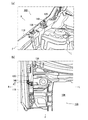
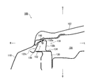
- FIG. 1 is a diagram showing a vehicle body front part structure 100 according to the present embodiment.
- FIG. 1A is a diagram of the right side of the vehicle body front part observed from the left front, and FIG. It is the figure which observed the vehicle body front part structure shown to 1 (a) from upper direction.
- FIG. 2 is a cross-sectional view taken along the line AA in FIG.
- the front hood 102 is not shown in FIGS. 1A and 1B, and the state in which the front fender 110 is transmitted is shown in FIG. 1B (FIG. 1). 2).
- the vehicle body front structure 100 includes a front hood 102 that covers an engine room 104 of a vehicle (the whole is not shown). Below the end of the front hood 102 in the vehicle width direction, a front fender 110 constituting the side surface of the vehicle body front structure 100 is disposed across both sides of the end of the front hood 102 in the vehicle width direction.
- a dash side member 120 which is a vehicle body structural member that extends in the vehicle front-rear direction, is disposed on the inner side and the lower side of the front fender 110 in the vehicle width direction.
- the dash side member 120 is exemplified as the vehicle body structural member.
- the present invention is not limited to this, and a member other than the dash side member 120 may be used as the vehicle body structural member.
- the dash side member 120 that is a vehicle body structural member is arranged on the inner side and the lower side of the front fender 110 in the vehicle width direction, but this is only an example, and the vehicle body structural member is a front fender. 110 should just be arrange
- the front fender 110 and the dash side member 120 are connected via a fender bracket 130.
- the fender bracket 130 of the present embodiment has a hat-shaped cross section that opens downward when viewed from the front of the vehicle.
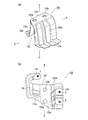
- FIG. 3 is a detailed view of the fender bracket 130 shown in FIGS. 1 and 2
- FIG. 3 (a) is a perspective view of the fender bracket 130
- FIG. 3 (b) is a view of the fender bracket 130 of FIG. 3 (a). It is the figure which observed from above.
- the fender bracket 130 of the present embodiment has a bulging portion 132, an inner flange 134, and an outer flange 136.
- the bulging portion 132 bulges upward, and the front fender is located on the top surface 132a on the vehicle inner side than the end portion of the front hood 102 in the vehicle width direction. 110 is fixed to the lower side (lower surface).
- bolt holes 133a and 133b are formed in the top surface 132a. Then, by inserting the bolt 140 into the bolt holes 133a and 133b, the fender bracket 130 is fixed to the front fender 110 as shown in FIG.
- the fixing by the bolt 140 is exemplified, but the present invention is not limited to this, and the fender bracket 130 and the front fender 110 may be fixed by other fixing methods.
- a vertical wall (hereinafter referred to as “below”) extends from the inner edge and the outer edge of the top surface 132 a in the vehicle width direction.
- the inner vertical wall 132b and the outer vertical wall 132c are respectively extended.
- an inner flange 134 extends inward in the vehicle width direction from the lower end of the inner vertical wall 132b, which is a vertical wall on the inner side in the vehicle width direction of the bulging portion 132.
- An outer flange 136 extends from the lower end of the outer vertical wall 132c, which is a wall, toward the outer side in the vehicle width direction.
- the inner flange 134 is fixed to the upper surface of the dash side member 120, which is a vehicle body structural member, at welding points A and B (see FIG. 3).
- the outer flange 136 is located above the dash side member 120 and serves as a release end.
- welding is exemplified in the fixing of the inner flange 134 to the dash side member 120, but the present invention is not limited to this, and it is also possible to fix them using other methods.
- the configuration in which the outer flange 136 is a release end at a position above the upper surface of the dash side member 120 is illustrated, but this is not a limitation, and the outer flange 136 is not limited to the dash side member 120. It may be located below the upper surface.
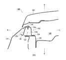
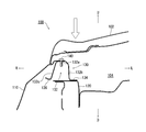
- FIG. 4 and 5 are diagrams for explaining a deformation state when a load from above is applied to the vehicle body front structure 100 shown in FIG.
- a load is applied to the front hood 102 from above in the vehicle body front structure 100 shown in FIG. 2
- the front hood 102 is deformed as shown in FIG.
- the lower end of the front hood 102 contacts the front fender 110, and the load applied to the front hood 102 is transmitted to the front fender 110.
- the outer flange 136 and the outer vertical wall 132c are deformed by the load, whereas the inner flange 134 is fixed to the upper surface of the dash side member 120. For this reason, as shown in FIGS. 4 and 5, the inner flange 134 and the inner vertical wall 132b continuous thereto do not move downward due to the load. That is, in the vehicle body front structure 100 of this embodiment, the inner vertical wall 132b does not contribute to load absorption. For this reason, it is not necessary to set the weak part like the conventional hollowing or a break point, and sufficient rigidity can be ensured in the fender bracket 130.
- the radius of curvature formed by the top surface 132a of the bulging portion 132 and the inner vertical wall 132b is formed by the outer vertical wall 132c of the bulging portion 132 and the top surface 132a. Greater than radius of curvature. Accordingly, when a load from above is transmitted through the front fender 110, the space between the top surface 132a of the bulging portion 132 and the inner vertical wall 132b is easily deformed, as shown in FIG. As a result, the outer vertical wall 132c can be moved downward without causing deformation of the inner vertical wall 132b. Therefore, it is possible to promote the downward movement of the outer vertical wall 132c while suppressing the deformation of the inner vertical wall 132b, and it is possible to further increase the load absorption performance described above.
- the case where the top surface 132a of the bulging portion 132 and the inner vertical wall 132b and the outer vertical wall 132c are curved is illustrated, but the present invention is not limited to this. May be bent. In that case, the bending angle formed between the top surface 132a of the bulging portion 132 and the inner vertical wall 132b may be larger than the bending angle formed between the outer vertical wall 132c and the top surface 132a of the bulging portion 132. Needless to say.
- the inner vertical wall 132b is substantially perpendicular to the top surface 132a of the bulging portion 132, and the outer vertical wall 132c is separated from the top surface 132a of the bulging portion 132. It is set to incline outward in the vehicle width direction. That is, in this embodiment, the inner vertical wall 132b and the outer vertical wall 132c extend downward at an asymmetric angle in the vehicle width direction.
- the inner vertical wall 132b can be increased in rigidity against a load from above, and deformation thereof is preferably prevented.
- the outer vertical wall 132c is inclined outward in the vehicle width direction, deformation (movement) toward the outer side in the vehicle width direction can be promoted. Therefore, more deformation strokes can be secured, and the load absorption performance can be further enhanced. Further, the outer vertical wall 132c moves along the outer side in the vehicle width direction of the dash side member 120 while moving along the outer vertical wall 132c, so that the outer vertical wall 132c can be used as a guide during deformation (when moving).
- an extension portion 138 is provided at a position extending from the outer flange 136 to the rear of the vehicle and spaced from the bulging portion 132 in the vehicle front-rear direction.
- the fender bracket 130 is fixed to the dash side member 120 (see FIG. 2), which is a vehicle body structural member, by welding at the welding point C in the extension 138.
- the fender bracket 130 is fixed to the dash side member 120 at the inner flange 134 and the extension portion 138 at a position diagonal to it. For this reason, the rigidity with respect to the tightening torque when the bolt 140 is used to fix the front fender 110 and the fender bracket 130 as in the present embodiment can be increased. Therefore, it is not necessary to increase the plate thickness to ensure rigidity, and it is possible to contribute to weight reduction of parts.
- the extension portion 138 is located at a position separated from the bulging portion 132, the above-described effect can be reliably obtained without inhibiting the deformation of the bulging portion 132 when a load from above is applied.
- the extension 138 and the outer flange 136 are continuous on a plane. Thereby, the continuous part of the extension part 138 and the outer flange 136 is easily deformed in the vertical direction. Therefore, it is possible to increase the fixing strength of the fender bracket 130 to the dash side member 120 without hindering the downward movement (deformation) of the outer flange 136 and the outer vertical wall 132c when a load from above is applied. It becomes.
- the extension portion 138 is provided at a position where the outer flange 136 extends rearward of the vehicle, but the present invention is not limited to this, and the extension portion is extended to a position where the outer flange 136 extends toward the front of the vehicle. Even if 138 is provided, the same effect can be obtained.
- the extension part 138 is being fixed to the dash side member 120 by welding, it is not limited also in this, They may be fixed by methods other than welding.
- the vertical wall (inner vertical wall 132b) on the inner side in the vehicle width direction and the vertical wall (outer vertical wall 132c) on the outer side in the vehicle width direction of the fender bracket 130 are respectively provided.
- the structure which provided a flange in the lower end of this was illustrated, it does not limit to this.
- a flange is provided at each lower end of the vertical wall on the inner side in the vehicle width direction and the vertical wall on the outer side in the vehicle width direction. There may be no configuration.
- the top surface of the fender bracket 130 is fixed to the lower side of the front fender 110 on the vehicle inner side than the end portion of the front hood 102 in the vehicle width direction, and the lower end of the vertical wall on the vehicle width direction inner side is the vehicle body structural member.
- the same effect as described above can also be obtained by fixing to the upper surface of the (dash side member 120) and using the lower end of the vertical wall on the outer side in the vehicle width direction as the open end.
- the present invention can be used for a vehicle body front structure including a front hood of a vehicle.
Abstract
Description
Claims (6)
- 車両のフロントフードを含む車体前部構造において、
前記フロントフードの車幅方向の端部の下方で該端部の車幅方向両側にわたって配置されるフロントフェンダと、
前記フロントフェンダの車幅方向内側または下側に配置され車両前後方向に延びる車体構造部材と、
車両前面視にて下方に開口したハット形状の断面を有するフェンダブラケットとを含み、
前記フェンダブラケットは、
前記フロントフードの車幅方向の端部よりも車内側で前記フロントフェンダの下側に固定される、上方に向かって膨出する膨出部と、
前記膨出部の車幅方向内側の縦壁の下端から車幅方向内側に向かって延びる内側フランジと、
前記膨出部の車幅方向外側の縦壁の下端から車幅方向外側に向かって延びる外側フランジとを有し、
前記内側フランジは、前記車体構造部材の上面に固定されていて、
前記外側フランジは、解放端となっていることを特徴とする車体前部構造。 In the vehicle body front structure including the front hood of the vehicle,
A front fender disposed below both ends of the front hood in the vehicle width direction below the vehicle width direction of the front hood;
A vehicle body structural member disposed on the inner side or the lower side of the front fender and extending in the vehicle longitudinal direction; and
A fender bracket having a hat-shaped cross-section opened downward in front view of the vehicle,
The fender bracket is
A bulging portion that bulges upward and is fixed to the lower side of the front fender on the vehicle inner side than the end of the front hood in the vehicle width direction;
An inner flange extending inward in the vehicle width direction from the lower end of the vertical wall on the inner side in the vehicle width direction of the bulging portion;
An outer flange extending from the lower end of the vertical wall on the outer side in the vehicle width direction of the bulging portion toward the outer side in the vehicle width direction;
The inner flange is fixed to the upper surface of the vehicle body structural member,
The vehicle body front structure, wherein the outer flange is an open end. - 前記フェンダブラケットは、前記外側フランジから車両前方または後方に延び前記膨出部から車両前後方向に離間した位置で前記車体構造部材に固定される延長部を更に有することを特徴とする請求項1に記載の車体前部構造。 The fender bracket further includes an extension portion that extends forward or rearward from the outer flange and is fixed to the vehicle body structural member at a position spaced from the bulging portion in the vehicle front-rear direction. Vehicle body front structure as described.
- 前記延長部と前記外側フランジは、平面で連続していることを特徴とする請求項2に記載の車体前部構造。 The vehicle body front structure according to claim 2, wherein the extension portion and the outer flange are continuous in a plane.
- 前記膨出部の天面と車幅方向内側の縦壁とがなす屈曲角または曲率半径は、該膨出部の天面との車幅方向外側の縦壁とがなす屈曲角または曲率半径よりも大きいことを特徴とする請求項1から3のいずれか1項に記載の車体前部構造。 The bending angle or curvature radius formed between the top surface of the bulging portion and the vertical wall inside in the vehicle width direction is greater than the bending angle or curvature radius formed between the top wall of the bulging portion and the vertical wall outside in the vehicle width direction. The vehicle body front part structure according to any one of claims 1 to 3, wherein the vehicle body front part structure is also large.
- 前記膨出部の車幅方向内側の縦壁は、該膨出部の天面に対してほぼ垂直であって、
前記膨出部の車幅方向外側の縦壁は、該膨出部の天面から離れるにしたがって車幅方向外側に傾斜していることを特徴とする請求項1から4のいずれか1項に記載の車体前部構造。 The vertical wall on the inner side in the vehicle width direction of the bulging portion is substantially perpendicular to the top surface of the bulging portion,
5. The vertical wall on the outer side in the vehicle width direction of the bulging portion is inclined outward in the vehicle width direction as the distance from the top surface of the bulging portion increases. Vehicle body front structure as described. - 車両のフロントフードを含む車体前部構造において、
前記フロントフードの車幅方向の端部の下方で該端部の車幅方向両側にわたって配置されるフロントフェンダと、
前記フロントフェンダの車幅方向内側または下側に配置され車両前後方向に延びる車体構造部材と、
車両前面視にて上方に向かって膨出し下方に開口したハット形状の断面を有するフェンダブラケットとを含み、
前記フェンダブラケットは、
天面が、前記フロントフードの車幅方向の端部よりも車内側で前記フロントフェンダの下側に固定されていて、
車幅方向内側の縦壁の下端が前記車体構造部材の上面に固定されていて、
車幅方向外側の縦壁の下端が解放端となっていることを特徴とする車体前部構造。 In the vehicle body front structure including the front hood of the vehicle,
A front fender disposed below both ends of the front hood in the vehicle width direction below the vehicle width direction of the front hood;
A vehicle body structural member disposed on the inner side or the lower side of the front fender and extending in the vehicle longitudinal direction; and
A fender bracket having a hat-shaped cross-section that bulges upward and opens downward in front view of the vehicle,
The fender bracket is
The top surface is fixed to the lower side of the front fender on the vehicle inner side than the end of the front hood in the vehicle width direction,
The lower end of the vertical wall on the inner side in the vehicle width direction is fixed to the upper surface of the vehicle body structural member,
A vehicle body front structure characterized in that the lower end of the vertical wall on the outer side in the vehicle width direction is an open end.
Priority Applications (2)
| Application Number | Priority Date | Filing Date | Title |
|---|---|---|---|
| CN201580000651.3A CN105164006B (en) | 2014-02-05 | 2015-02-03 | Vehicle-body front structure |
| DE112015000052.6T DE112015000052T5 (en) | 2014-02-05 | 2015-02-03 | Vehicle body front structure |
Applications Claiming Priority (2)
| Application Number | Priority Date | Filing Date | Title |
|---|---|---|---|
| JP2014-020310 | 2014-02-05 | ||
| JP2014020310A JP6237290B2 (en) | 2014-02-05 | 2014-02-05 | Body front structure |
Publications (1)
| Publication Number | Publication Date |
|---|---|
| WO2015119106A1 true WO2015119106A1 (en) | 2015-08-13 |
Family
ID=53777911
Family Applications (1)
| Application Number | Title | Priority Date | Filing Date |
|---|---|---|---|
| PCT/JP2015/052972 WO2015119106A1 (en) | 2014-02-05 | 2015-02-03 | Vehicle-body front structure |
Country Status (4)
| Country | Link |
|---|---|
| JP (1) | JP6237290B2 (en) |
| CN (1) | CN105164006B (en) |
| DE (1) | DE112015000052T5 (en) |
| WO (1) | WO2015119106A1 (en) |
Cited By (1)
| Publication number | Priority date | Publication date | Assignee | Title |
|---|---|---|---|---|
| CN111942474A (en) * | 2019-05-15 | 2020-11-17 | 本田技研工业株式会社 | Vehicle body front structure |
Families Citing this family (3)
| Publication number | Priority date | Publication date | Assignee | Title |
|---|---|---|---|---|
| JP2019107987A (en) * | 2017-12-18 | 2019-07-04 | スズキ株式会社 | Structure of vehicle body front part |
| JP7180294B2 (en) | 2018-11-08 | 2022-11-30 | スズキ株式会社 | Body front structure |
| JP7347255B2 (en) * | 2020-02-20 | 2023-09-20 | マツダ株式会社 | Vehicle front body structure |
Citations (5)
| Publication number | Priority date | Publication date | Assignee | Title |
|---|---|---|---|---|
| JP2002337745A (en) * | 2001-05-18 | 2002-11-27 | Fuji Heavy Ind Ltd | Front body structure of vehicle |
| JP2005014763A (en) * | 2003-06-26 | 2005-01-20 | Toyota Motor Corp | Fender panel mounting structure |
| JP2008105548A (en) * | 2006-10-25 | 2008-05-08 | Toyota Motor Corp | Fender panel mounting structure for vehicle |
| DE102011011513A1 (en) * | 2011-02-17 | 2012-08-23 | Daimler Ag | Mounting arrangement for mounting mudguard on body of motor vehicle i.e. passenger car, has bent attachment element indirectly connecting mudguard with front longitudinal beam of body of vehicle |
| JP2012176636A (en) * | 2011-02-25 | 2012-09-13 | Mazda Motor Corp | Front structure of vehicle |
Family Cites Families (5)
| Publication number | Priority date | Publication date | Assignee | Title |
|---|---|---|---|---|
| JP3799963B2 (en) * | 2000-05-25 | 2006-07-19 | マツダ株式会社 | Vehicle front structure |
| KR100371278B1 (en) * | 2000-11-30 | 2003-02-07 | 현대자동차주식회사 | Fender panel impact absorption structure with walker protection function in car |
| JP4736609B2 (en) * | 2005-08-05 | 2011-07-27 | マツダ株式会社 | Car fender panel mounting structure |
| EP1892162A3 (en) * | 2006-08-21 | 2009-12-02 | Alutech Gesellschaft m.b.H. | Pedestrian protection for a motor vehicle |
| US8182027B2 (en) * | 2009-06-15 | 2012-05-22 | Toyota Motor Engineering & Manufacturing North America, Inc. | Fender structure assemblies for vehicles |
-
2014
- 2014-02-05 JP JP2014020310A patent/JP6237290B2/en active Active
-
2015
- 2015-02-03 CN CN201580000651.3A patent/CN105164006B/en not_active Expired - Fee Related
- 2015-02-03 DE DE112015000052.6T patent/DE112015000052T5/en active Granted
- 2015-02-03 WO PCT/JP2015/052972 patent/WO2015119106A1/en active Application Filing
Patent Citations (5)
| Publication number | Priority date | Publication date | Assignee | Title |
|---|---|---|---|---|
| JP2002337745A (en) * | 2001-05-18 | 2002-11-27 | Fuji Heavy Ind Ltd | Front body structure of vehicle |
| JP2005014763A (en) * | 2003-06-26 | 2005-01-20 | Toyota Motor Corp | Fender panel mounting structure |
| JP2008105548A (en) * | 2006-10-25 | 2008-05-08 | Toyota Motor Corp | Fender panel mounting structure for vehicle |
| DE102011011513A1 (en) * | 2011-02-17 | 2012-08-23 | Daimler Ag | Mounting arrangement for mounting mudguard on body of motor vehicle i.e. passenger car, has bent attachment element indirectly connecting mudguard with front longitudinal beam of body of vehicle |
| JP2012176636A (en) * | 2011-02-25 | 2012-09-13 | Mazda Motor Corp | Front structure of vehicle |
Cited By (2)
| Publication number | Priority date | Publication date | Assignee | Title |
|---|---|---|---|---|
| CN111942474A (en) * | 2019-05-15 | 2020-11-17 | 本田技研工业株式会社 | Vehicle body front structure |
| CN111942474B (en) * | 2019-05-15 | 2022-12-27 | 本田技研工业株式会社 | Vehicle body front structure |
Also Published As
| Publication number | Publication date |
|---|---|
| JP2015147458A (en) | 2015-08-20 |
| CN105164006B (en) | 2017-03-22 |
| JP6237290B2 (en) | 2017-11-29 |
| DE112015000052T5 (en) | 2016-01-14 |
| CN105164006A (en) | 2015-12-16 |
Similar Documents
| Publication | Publication Date | Title |
|---|---|---|
| JP6459839B2 (en) | Vehicle skeleton structure | |
| JP5999134B2 (en) | Vehicle front structure | |
| JP2009143257A (en) | Vehicle body structure | |
| JP2009073368A (en) | Bumper mounting part structure | |
| JP2009214561A (en) | Vehicle body structure of automobile | |
| WO2015119106A1 (en) | Vehicle-body front structure | |
| JP6060873B2 (en) | Rear body structure of the vehicle | |
| JP6252572B2 (en) | Body front structure | |
| US9849913B2 (en) | Vehicle front section structure | |
| CN108944775B (en) | Vehicle body front structure | |
| JP2019038301A (en) | Body structure | |
| JP2010115946A (en) | Vehicle body front part structure | |
| JP2013144501A (en) | Vehicle body structure | |
| KR101251751B1 (en) | Connecting structure of vehicle front body | |
| JP2008001149A (en) | Structure of side portion of vehicle | |
| JP2006096193A (en) | Vehicle body structure | |
| JP5831130B2 (en) | Front pillar structure | |
| JP6493184B2 (en) | Vehicle side structure | |
| KR102567277B1 (en) | Structure of side sill for vehicle | |
| JP6024808B2 (en) | Auto body front structure | |
| JP6225879B2 (en) | Vehicle front structure | |
| JP6477263B2 (en) | Vehicle door structure | |
| JP6252354B2 (en) | Vehicle side structure | |
| JP6221128B2 (en) | Body front structure | |
| WO2020256042A1 (en) | Frame structure |
Legal Events
| Date | Code | Title | Description |
|---|---|---|---|
| WWE | Wipo information: entry into national phase |
Ref document number: 201580000651.3 Country of ref document: CN |
|
| 121 | Ep: the epo has been informed by wipo that ep was designated in this application |
Ref document number: 15746340 Country of ref document: EP Kind code of ref document: A1 |
|
| WWE | Wipo information: entry into national phase |
Ref document number: IDP00201507042 Country of ref document: ID Ref document number: 112015000052 Country of ref document: DE Ref document number: 1120150000526 Country of ref document: DE |
|
| 122 | Ep: pct application non-entry in european phase |
Ref document number: 15746340 Country of ref document: EP Kind code of ref document: A1 |