EP2933685B1 - Cartouche de traitement et dispositif de formation d'image - Google Patents
Cartouche de traitement et dispositif de formation d'image Download PDFInfo
- Publication number
- EP2933685B1 EP2933685B1 EP13862540.5A EP13862540A EP2933685B1 EP 2933685 B1 EP2933685 B1 EP 2933685B1 EP 13862540 A EP13862540 A EP 13862540A EP 2933685 B1 EP2933685 B1 EP 2933685B1
- Authority
- EP
- European Patent Office
- Prior art keywords
- roller
- driving force
- developer supplying
- developing
- developing roller
- Prior art date
- Legal status (The legal status is an assumption and is not a legal conclusion. Google has not performed a legal analysis and makes no representation as to the accuracy of the status listed.)
- Active
Links
- 238000000034 method Methods 0.000 title claims description 124
- 230000008569 process Effects 0.000 title claims description 119
- 230000015572 biosynthetic process Effects 0.000 title description 6
- 230000002093 peripheral effect Effects 0.000 claims description 25
- 230000005484 gravity Effects 0.000 claims description 15
- 230000008878 coupling Effects 0.000 description 52
- 238000010168 coupling process Methods 0.000 description 52
- 238000005859 coupling reaction Methods 0.000 description 52
- 238000012546 transfer Methods 0.000 description 26
- 238000004140 cleaning Methods 0.000 description 17
- 239000000463 material Substances 0.000 description 16
- 238000003756 stirring Methods 0.000 description 16
- 238000007599 discharging Methods 0.000 description 6
- 230000000694 effects Effects 0.000 description 4
- 238000003780 insertion Methods 0.000 description 4
- 230000037431 insertion Effects 0.000 description 4
- 230000007246 mechanism Effects 0.000 description 4
- 238000011144 upstream manufacturing Methods 0.000 description 4
- 230000005540 biological transmission Effects 0.000 description 3
- 239000003086 colorant Substances 0.000 description 3
- 230000007423 decrease Effects 0.000 description 3
- 238000011161 development Methods 0.000 description 3
- 230000018109 developmental process Effects 0.000 description 3
- 230000006835 compression Effects 0.000 description 2
- 238000007906 compression Methods 0.000 description 2
- 230000003247 decreasing effect Effects 0.000 description 2
- 238000005192 partition Methods 0.000 description 2
- 230000035515 penetration Effects 0.000 description 2
- 230000009467 reduction Effects 0.000 description 2
- 230000003746 surface roughness Effects 0.000 description 2
- 238000005299 abrasion Methods 0.000 description 1
- 230000008901 benefit Effects 0.000 description 1
- 230000033228 biological regulation Effects 0.000 description 1
- 239000000969 carrier Substances 0.000 description 1
- 210000000078 claw Anatomy 0.000 description 1
- 239000000470 constituent Substances 0.000 description 1
- 230000007547 defect Effects 0.000 description 1
- 230000001419 dependent effect Effects 0.000 description 1
- 238000013461 design Methods 0.000 description 1
- 238000012423 maintenance Methods 0.000 description 1
- 230000001105 regulatory effect Effects 0.000 description 1
Images


Classifications
-
- G—PHYSICS
- G03—PHOTOGRAPHY; CINEMATOGRAPHY; ANALOGOUS TECHNIQUES USING WAVES OTHER THAN OPTICAL WAVES; ELECTROGRAPHY; HOLOGRAPHY
- G03G—ELECTROGRAPHY; ELECTROPHOTOGRAPHY; MAGNETOGRAPHY
- G03G21/00—Arrangements not provided for by groups G03G13/00 - G03G19/00, e.g. cleaning, elimination of residual charge
- G03G21/16—Mechanical means for facilitating the maintenance of the apparatus, e.g. modular arrangements
- G03G21/18—Mechanical means for facilitating the maintenance of the apparatus, e.g. modular arrangements using a processing cartridge, whereby the process cartridge comprises at least two image processing means in a single unit
- G03G21/1803—Arrangements or disposition of the complete process cartridge or parts thereof
-
- G—PHYSICS
- G03—PHOTOGRAPHY; CINEMATOGRAPHY; ANALOGOUS TECHNIQUES USING WAVES OTHER THAN OPTICAL WAVES; ELECTROGRAPHY; HOLOGRAPHY
- G03G—ELECTROGRAPHY; ELECTROPHOTOGRAPHY; MAGNETOGRAPHY
- G03G21/00—Arrangements not provided for by groups G03G13/00 - G03G19/00, e.g. cleaning, elimination of residual charge
- G03G21/16—Mechanical means for facilitating the maintenance of the apparatus, e.g. modular arrangements
- G03G21/18—Mechanical means for facilitating the maintenance of the apparatus, e.g. modular arrangements using a processing cartridge, whereby the process cartridge comprises at least two image processing means in a single unit
- G03G21/1839—Means for handling the process cartridge in the apparatus body
- G03G21/1857—Means for handling the process cartridge in the apparatus body for transmitting mechanical drive power to the process cartridge, drive mechanisms, gears, couplings, braking mechanisms
-
- G—PHYSICS
- G03—PHOTOGRAPHY; CINEMATOGRAPHY; ANALOGOUS TECHNIQUES USING WAVES OTHER THAN OPTICAL WAVES; ELECTROGRAPHY; HOLOGRAPHY
- G03G—ELECTROGRAPHY; ELECTROPHOTOGRAPHY; MAGNETOGRAPHY
- G03G15/00—Apparatus for electrographic processes using a charge pattern
- G03G15/06—Apparatus for electrographic processes using a charge pattern for developing
- G03G15/08—Apparatus for electrographic processes using a charge pattern for developing using a solid developer, e.g. powder developer
- G03G15/0896—Arrangements or disposition of the complete developer unit or parts thereof not provided for by groups G03G15/08 - G03G15/0894
-
- G—PHYSICS
- G03—PHOTOGRAPHY; CINEMATOGRAPHY; ANALOGOUS TECHNIQUES USING WAVES OTHER THAN OPTICAL WAVES; ELECTROGRAPHY; HOLOGRAPHY
- G03G—ELECTROGRAPHY; ELECTROPHOTOGRAPHY; MAGNETOGRAPHY
- G03G21/00—Arrangements not provided for by groups G03G13/00 - G03G19/00, e.g. cleaning, elimination of residual charge
- G03G21/06—Eliminating residual charges from a reusable imaging member
- G03G21/08—Eliminating residual charges from a reusable imaging member using optical radiation
-
- G—PHYSICS
- G03—PHOTOGRAPHY; CINEMATOGRAPHY; ANALOGOUS TECHNIQUES USING WAVES OTHER THAN OPTICAL WAVES; ELECTROGRAPHY; HOLOGRAPHY
- G03G—ELECTROGRAPHY; ELECTROPHOTOGRAPHY; MAGNETOGRAPHY
- G03G21/00—Arrangements not provided for by groups G03G13/00 - G03G19/00, e.g. cleaning, elimination of residual charge
- G03G21/16—Mechanical means for facilitating the maintenance of the apparatus, e.g. modular arrangements
- G03G21/18—Mechanical means for facilitating the maintenance of the apparatus, e.g. modular arrangements using a processing cartridge, whereby the process cartridge comprises at least two image processing means in a single unit
- G03G21/1839—Means for handling the process cartridge in the apparatus body
- G03G21/1857—Means for handling the process cartridge in the apparatus body for transmitting mechanical drive power to the process cartridge, drive mechanisms, gears, couplings, braking mechanisms
- G03G21/186—Axial couplings
-
- G—PHYSICS
- G03—PHOTOGRAPHY; CINEMATOGRAPHY; ANALOGOUS TECHNIQUES USING WAVES OTHER THAN OPTICAL WAVES; ELECTROGRAPHY; HOLOGRAPHY
- G03G—ELECTROGRAPHY; ELECTROPHOTOGRAPHY; MAGNETOGRAPHY
- G03G15/00—Apparatus for electrographic processes using a charge pattern
- G03G15/06—Apparatus for electrographic processes using a charge pattern for developing
- G03G15/08—Apparatus for electrographic processes using a charge pattern for developing using a solid developer, e.g. powder developer
- G03G15/0806—Apparatus for electrographic processes using a charge pattern for developing using a solid developer, e.g. powder developer on a donor element, e.g. belt, roller
- G03G15/0808—Apparatus for electrographic processes using a charge pattern for developing using a solid developer, e.g. powder developer on a donor element, e.g. belt, roller characterised by the developer supplying means, e.g. structure of developer supply roller
-
- G—PHYSICS
- G03—PHOTOGRAPHY; CINEMATOGRAPHY; ANALOGOUS TECHNIQUES USING WAVES OTHER THAN OPTICAL WAVES; ELECTROGRAPHY; HOLOGRAPHY
- G03G—ELECTROGRAPHY; ELECTROPHOTOGRAPHY; MAGNETOGRAPHY
- G03G21/00—Arrangements not provided for by groups G03G13/00 - G03G19/00, e.g. cleaning, elimination of residual charge
- G03G21/16—Mechanical means for facilitating the maintenance of the apparatus, e.g. modular arrangements
- G03G21/18—Mechanical means for facilitating the maintenance of the apparatus, e.g. modular arrangements using a processing cartridge, whereby the process cartridge comprises at least two image processing means in a single unit
- G03G21/1803—Arrangements or disposition of the complete process cartridge or parts thereof
- G03G21/1817—Arrangements or disposition of the complete process cartridge or parts thereof having a submodular arrangement
- G03G21/1825—Pivotable subunit connection
-
- G—PHYSICS
- G03—PHOTOGRAPHY; CINEMATOGRAPHY; ANALOGOUS TECHNIQUES USING WAVES OTHER THAN OPTICAL WAVES; ELECTROGRAPHY; HOLOGRAPHY
- G03G—ELECTROGRAPHY; ELECTROPHOTOGRAPHY; MAGNETOGRAPHY
- G03G21/00—Arrangements not provided for by groups G03G13/00 - G03G19/00, e.g. cleaning, elimination of residual charge
- G03G21/16—Mechanical means for facilitating the maintenance of the apparatus, e.g. modular arrangements
- G03G21/18—Mechanical means for facilitating the maintenance of the apparatus, e.g. modular arrangements using a processing cartridge, whereby the process cartridge comprises at least two image processing means in a single unit
- G03G21/1839—Means for handling the process cartridge in the apparatus body
- G03G21/1842—Means for handling the process cartridge in the apparatus body for guiding and mounting the process cartridge, positioning, alignment, locks
- G03G21/185—Means for handling the process cartridge in the apparatus body for guiding and mounting the process cartridge, positioning, alignment, locks the process cartridge being mounted parallel to the axis of the photosensitive member
-
- G—PHYSICS
- G03—PHOTOGRAPHY; CINEMATOGRAPHY; ANALOGOUS TECHNIQUES USING WAVES OTHER THAN OPTICAL WAVES; ELECTROGRAPHY; HOLOGRAPHY
- G03G—ELECTROGRAPHY; ELECTROPHOTOGRAPHY; MAGNETOGRAPHY
- G03G2221/00—Processes not provided for by group G03G2215/00, e.g. cleaning or residual charge elimination
- G03G2221/16—Mechanical means for facilitating the maintenance of the apparatus, e.g. modular arrangements and complete machine concepts
- G03G2221/1651—Mechanical means for facilitating the maintenance of the apparatus, e.g. modular arrangements and complete machine concepts for connecting the different parts
- G03G2221/1657—Mechanical means for facilitating the maintenance of the apparatus, e.g. modular arrangements and complete machine concepts for connecting the different parts transmitting mechanical drive power
Definitions
- the present invention relates to a process cartridge according to the preamble of claim 1 and an image forming apparatus according to the preamble of claim 9.
- the image forming apparatus forms an image on a recording material using an image forming process.
- Examples of the image forming apparatus include a printer, a copying machine, a facsimile machine, or wordprocessor and a multi-function machine of these machines.
- a photosensitive drum and process parts actable on the photosensitive drum are unfixed into a cartridge.
- a process cartridge type in which this cartridge is detachably mountable to an apparatus main assembly of the image forming apparatus is employed.
- a constitution in which a plurality of process cartridges are arranged below the transfer belt is used. This is because in the case of a constitution in which a print is discharged onto an upper surface of the image forming apparatus, by disposing the process cartridges below the transfer belt, a first print time can be shortened.
- a process cartridge corresponding to this constitution a constitution in which a developing chamber is disposed at an upper portion close to the transfer belt and a developer is scooped up, to the developing chamber, from a developer accommodating chamber disposed below the developing chamber is used ( JP 2008-170951 A ).
- JP 2008-170951 A there was a need to provide the stirring member in the developing chamber in a side below a contact portion between a developing roller and a developer supplying roller in the developing chamber. Therefore, the developer supplying roller for supplying the developer to the developing roller is rotated in a rotational direction opposite to rotational direction of the developing roller, so that circulation of the developer is made equivalent to or more than a conventional level without providing the stirring member in the developing chamber, and a supplying property of the developer from the developer supplying roller to the developing roller can be satisfied. According to this constitution, a space conventionally ensured for disposing the stirring member can be filled, and therefore a residual of the developer can be further suppressed.
- US 2011/222916 A1 shows a generic process cartridge according to the preamble of claim 1.
- the process cartridge comprises (i) a photosensitive drum; (ii) a rotatable developing roller for developing an electrostatic latent image formed on said photosensitive drum; (iii) a developer supplying roller, provided in contact with said developing roller, for supplying a developer to said developing roller; (iv) a driving force receiving portion for receiving a driving force for rotating said developer supplying roller and said developing roller, wherein said driving force receiving portion is provided at a shaft end portion of said developer supplying roller; (v) a first driving force transmitting portion for transmitting the driving force, received by said driving force receiving portion, to said developing roller; and (vi) a second driving force transmitting portion, provided on said developing roller, for transmitting the driving force from said first driving force transmitting portion to said developing roller by engaging with said driving force transmitting portion.
- US 2011/222916 A1 shows a generic image forming apparatus according to the preamble of claim 9 including a main assembly and such a process cartridge as mentioned-above, wherein (i) said main assembly includes (i-i) a driving portion; and (ii) said process cartridge is detachably mountable to said image forming apparatus.
- US 2008/298847 A1 shows a developing device using a two-component developer including at least carriers and toners.
- the toners are supplied to an image bearing member bearing an electrostatic latent image so that a toner image is developed from the electrostatic latent image.
- the developing device has a developing roller arranged to oppose the image bearing member; and a magnetic roller arranged to oppose the developing roller.
- the magnetic roller retains the two-component developer to supply toners to the developing roller.
- the developing roller and the magnetic roller are rotationally driven in directions to be opposite from one another at an opposed position, and a magnetic pole of the magnetic roller and a magnetic pole of the developing roller have magnetic polarities different from one another at the opposed position.
- a surface roughness of the magnetic roller is greater than a surface roughness of the developing roller.
- US 2012/195634 A1 shows a cartridge including a developing roller, a supply roller, an input rotary body, a developing roller rotary body, and a supply roller rotary body.
- the developing roller/supply roller rotary bodies transmit the drive force inputted from the input rotary body to the developing roller/supply roller, respectively.
- the developing roller rotary body includes first and second drive input parts having different diameters.
- the input rotary body includes first and second drive output parts engaged with the first and second drive input part, respectively and having different diameters.
- the first drive output part is movable between a first position and a second position. The first drive input part and the first drive output part are engaged when the first drive output part is in the first position.
- the second drive input part and the second drive output part are engaged when the first drive output part is in the second position.
- US 2012/237266 A1 shows a developing apparatus and an image forming apparatus, in which a driving force produced by a first driving motor is transmitted to a developing roller and an intermediate application roller by a first drive transmission unit, and the developing roller and the intermediate application roller are rotated as a result.
- the developing roller and the intermediate application roller thus take the first driving motor as a drive source, and receive the driving force from the first driving motor via the same first drive transmission unit.
- US 2011/280621 A1 shows a process cartridge detachably mountable to a main assembly of an electrophotographic image forming apparatus and including a charging roller for charging a surface of the photosensitive drum by being urged and contacted to a photosensitive drum; a link engaged with an end of a rotation shaft of the charging roller; a locking member, locked with the link in a state that charging roller is spaced from the drum, for holding a spaced state of the charging roller from drum; the developing unit including a gear train for transmitting an externally inputted driving force to a member provided in the developing unit: a space releasing member for contacting and moving the link to release the link from the locking member, thereby to cease the spaced state of the charging roller, the space releasing member being provided with a drive receiving portion; a connecting member including an input gear portion for receiving a driving force from the gear train, and a drive transmitting portion engageable with the drive receiving portion; wherein a play is provided between the drive receiving portion and the drive transmitting portion in a direction of movement of
- US 5 583 630 A shows a joint which has an OLDHAM state coupling at a leading edge thereof and is held movably in a direction which is parallel to a joint axis at a full-color printer body.
- a coupling gear is substantially connected to a developing roller disposed in each mono-color developing unit, which makes up a revolving type developing device.
- the joint is capable of moving in parallel to the axis of the joint in the state of being rotated toward the coupling.
- a projection is further provided at the leading edge of the coupling, and a claw is further provided at the end of the coupling gear.
- the object of the present invention is achieved by a process cartridge having the features of claim 1 and an image forming apparatus having the features of claim 9.
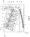
- an electrophotographic image forming apparatus (hereinafter referred to as an "image forming apparatus") 100 will be described using Figure 2 .
- detachably mountable four process cartridges 70 (70Y, 70M, 70C, 70K) are detachably mounted by mounting members (unshown).
- an upstream side of the process cartridge 70 with respect to a mounting direction to the image forming apparatus 100 is defined as a front (surface) side
- a downstream side of the process cartridge 70 with respect to the mounting direction is defined as a rear (surface) side.
- the respective process cartridges 70 are inclined and juxtaposed in an apparatus main assembly 100A with respect to a horizontal direction ht.
- the process cartridge 70 includes electrophotographic photosensitive drums (hereinafter referred to as "photosensitive drums") 1 (1a, 1b, 1c, 1d), and at a periphery of the photosensitive drums 1, process means such as charging rollers 2 (2a, 2b, 2c, 2d), developing rollers 25 (25a, 25b, 25c, 25d), and cleaning members 6 (6a, 6b, 6c, 6d) are integrally provided.
- photosensitive drums electrophotographic photosensitive drums
- the charging roller 2 electrically charges the surface of the photosensitive drum 1 uniformly, and the developing roller 25 develops a latent image, formed on the photosensitive drum 1, with a toner to visualize the latent image.
- the cleaning member 6 removes the toner remaining on the photosensitive drum 1 after a toner image formed on the photosensitive drum 1 is transferred onto a recording material (medium).
- a scanner unit 3 for forming the latent image on the photosensitive drums 1 by subjecting the photosensitive drums 1 to selective exposure to light on the basis of image information is provided.
- a cassette 17 in which sheets of the recording material S are accommodated is mounted at a lower portion of the apparatus main assembly 100A. Further, a recording material feeding portion is provided so that the recording material S can be fed to an upper portion of the apparatus main assembly 100A by being passed through a secondary transfer roller 69 and a fixing portion 74. That is, a feeding roller 54 for separating and feeding the sheets of the recording material S in the cassette 17 in a one-by-one manner, a feeding roller pair 76 for feeding the fed recording material S, and a registration roller pair 55 for synchronizing the latent image formed on the photosensitive drum 1 with the recording material S are provided.
- an intermediary transfer unit 5 as an intermediary transfer means onto which the toner image formed on each of the photosensitive drums 1 (1a, 1b, 1c, 1d) is to be transferred is provided.
- the intermediary transfer unit 5 includes a driving roller 56, a follower roller 57, primary transfer rollers 58 (58a, 58b, 58c, 58d) at positions opposing the photosensitive drums 1 for the respective colors, and an opposite roller 59 at a position opposing the secondary transfer roller 69 are provided.
- a transfer belt (intermediary transfer belt) 9 is extended and stretched.
- the transfer belt 9 is circulated and moved so as to oppose and be contacted to all of the photosensitive drums 1, so that primary transfer (of the toner images) from the photosensitive drums 1 onto the transfer belt 9 is made by applying a voltage to the primary transfer rollers 58 (58a, 58b, 58c, 58d). Then, by voltage application to the secondary transfer roller 69 and the opposite roller 59 disposed inside the transfer belt 9, the toner images are transferred from the transfer belt 9 onto the recording material S.
- the photosensitive drum 1 uniformly charged by the charging roller 2 is subjected to selective exposure to light emitted from the scanner unit 3. By this, an electrostatic latent image is formed on the photosensitive drum 1.
- the latent image is developed by the developing roller 25.
- the toner images of the respective colors are formed on the photosensitive drums 1, respectively.
- the registration roller pair 55 feeds the recording material S to a secondary transfer position where the secondary transfer roller 69 opposing the opposite roller 59 is contacted to the transfer belt 9.
- the respective color toner images are secondary-transferred from the transfer belt 9 onto the recording material S.
- a color image is formed on the recording material S.
- the recording material S on which the color image is formed is heated and pressed by the fixing portion 74, so that the toner images are fixed on the recording material S.
- the recording material S is discharged onto a discharge portion 75 by a (sheet-)discharging roller pair 72.
- the fixing portion 74 is disposed at an upper portion of the apparatus main assembly 100A.
- FIG. 3 is a principal sectional view of the process cartridge 70 in which the toner is accommodated.
- the process cartridge 70Y accommodating the toner of yellow
- the process cartridge 70M accommodating the toner of magenta
- the process cartridge 70C accommodating the toner of cyan
- the process cartridge 70K accommodating the toner of black have the same constitution.
- the respective process cartridges 70 include drum units 26 (26a, 26b, 26c, 26d) as a first unit and developing units 4 (4a, 4b, 4c, 4d) as a second unit.
- the drum unit 26 includes the photosensitive drum 1 (1a, 1b, 1c, 1d), the charging roller 2 (2a, 2b, 2c, 2d) and the cleaning member 6 (6a, 6b, 6c, 6d).
- the developing unit 4 includes the developing roller 25.
- the photosensitive drum 1 is rotatably mounted via a front drum bearing 10 and a rear drum bearing 11.
- the photosensitive drum 1 is provided with a drum coupling 16 and a flange 19 at an end portion thereof.
- the cleaning member 6 is constituted by an elastic member formed with a rubber blade and a cleaning supporting member 8. A free end portion of the elastic member disposed in contact with the photosensitive drum 1 counter directionally to a rotational direction of the photosensitive drum 1. Further, a residual toner removed from the surface of the photosensitive drum 1 by the cleaning member 6 falls into a removed toner chamber 27a. Further, a receptor sheet 29 for preventing leakage of the removed toner in the removed toner chamber 27a is contacted to the photosensitive drum 1.
- the charging roller 2 is rotatably mounted to the drum unit 26 via a charging roller bearing 28 and is urged against the photosensitive drum 1 by a charging roller urging member 46, thus being rotated by the rotation of the photosensitive drum 1.
- the developing unit 4 includes the developing roller 25, rotating in contact with the photosensitive drum 1 in an arrow B direction, and a developing device frame 31 for supporting the developing roller 25. Further, the developing unit 4 is constituted by a developing chamber 31b in which the developing roller 25 is disposed and by a toner accommodating portion 31c, disposed below the developing chamber 31b with respect to the direction of gravity in a state in which the process cartridge is mounted in the image forming apparatus, as a developer accommodating container for accommodating the toner. These chambers (portions) are partitioned by a partition wall 31d. The toner accommodating portion 31 is positioned below the developing roller 25 and the developer supplying roller with respect to the direction of gravity.
- the partition wall 31d is provided with an opening 31e through which the toner passes when the toner is fed from the toner accommodating portion 31c to the developing chamber 31b.
- the developing roller 25 is rotatably supported by the developing (device) frame 31 via a front developing (means) bearing 12 and a rear developing (means) bearing 13 provided in both sides of the developing device frame 31, respectively ( Figure 3 ).
- a developer supplying roller 34 rotatable in contact with the developing roller 25 in an arrow E direction, and a developing blade 35 for regulating a toner layer on the developing roller 25 are provided.
- the developer supplying roller 34 is constituted by a metal-made developer supplying roller shaft 34j and a sponge portion 34a which is an elastic portion for covering an outer peripheral surface of the shaft in an exposed state at end portions.
- the developer supplying roller 34 is disposed so that the sponge portion 34a is in contacted to the developing roller 25 with a predetermined penetration amount into the developing roller 25.
- a leakage-out preventing sheet 33 as a developing (means) contact sheet for preventing leakage-out of the toner from the developing frame 31 contacting the developing roller 25 is provided.
- a toner feeding member 36 which is a feeding means for feeding the toner into the developing chamber 31b through the opening 31e while stirring the toner accommodated in the toner accommodating chamber 31c is provided.
- the toner accommodating portion 31c is provided below with respect to the direction of gravity, and therefore also the toner feeding member 36 is positioned below the developing chamber 31b with respect to the direction of gravity. That is, the developing chamber 70 in this embodiment has a toner scooping-up constitution in which the toner is fed by the toner feeding member 36 against gravitation from the toner accommodating portion 31c disposed at a lower portion with respect to the direction of gravity to the developing chamber 31b disposed at an upper portion of the toner accommodating portion 31c with respect to the direction of gravity.
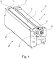
- Figure 4 is a general perspective view of the process cartridge 70.
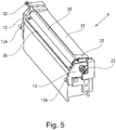
- Figure 5 is a general perspective view of the developing unit 4.
- the developing unit 4 is rotatably mounted.
- a front supporting pin 14 and a rear supporting pin 15 which are press-fitted in the cleaning frame 27 are engaged with hang holes 12a and 13a, respectively, of the rear developing bearing 13.
- the developing unit 4 is rotatably supported by the cleaning frame 27 with the front supporting pin 14 and the rear supporting pin 15 as rotation shafts.
- the cleaning frame 27 is provided with a front drum bearing 10 and a rear drum bearing 11 which rotatably support the photosensitive drum 1.
- the rear drum bearing 11 supports a drum coupling 16 coupled to the photosensitive drum 1.
- the front drum bearing 10 supports the flange 19.
- the drum coupling 16 is a drum coupling member for transmitting a rotational driving force (first rotational driving force) from the apparatus main assembly 100A to the photosensitive drum 1.
- the developing frame 31 is provided with the front and rear developing bearings 12 and 13 for rotatably supporting the developing roller 25. Further, the developing unit 4 is constituted so as to be urged against the drum unit 26, during image formation of the process cartridge 70, by an urging spring 32 provided at each of ends of the developing frame 31. By these urging spring 32, an urging force for bringing the developing roller 25 into contact with the photosensitive drum 1 with, as rotation centers, the hang holes 12a and 13a of the front and rear developing bearings 12 and 13 is generated.
- a constitution in which the process cartridge 70 is inserted into the image forming apparatus 100 will be described.
- a constitution in which the process cartridges 70 (70Y, 70M, 70C, 70K) are inserted through openings 101 (101a, 101b, 101c, 101d) of the image forming apparatus 100 is a constitution in which the process cartridges 70 are inserted from the front side to the rear side in a direction (arrow F direction in the figure) parallel to an axial direction of the photosensitive drums 1 (1a, 1b, 1c, 1d).
- an upstream side is defined as a front side
- a downstream side is defined as a rear side.
- main assembly upper mounting guide portions 103 (103a, 103b, 103c, 103d) which are first main assembly guide portions are provided in an upper side.
- main assembly lower mounting guide portions 102 (102a, 102b, 102c, 102d) which are second main assembly mounting guide portions are provided in a lower side.
- Each of the main assembly upper guide portions 103 and the main assembly lower guide portions 102 has a guide shape extending along an insertion direction F of each of the process cartridge 70.
- the process cartridge 70 is placed in a front side of the main assembly lower mounting guide portion 102 with respect to a mounting direction and then is moved in the insertion direction F along the main assembly upper and lower mounting guide portions 102 and 103, thus being inserted into the image forming apparatus 100.
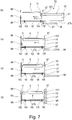
- Figure 7(a) is a schematic view for illustrating a state before mounting of the process cartridge 70 into the apparatus main assembly 100A.
- Figure 7(b) is a schematic view for illustrating a state during the mounting of the process cartridge 70 into the apparatus main assembly 100A.
- the main assembly lower mounting guide portion 102 provided in the apparatus main assembly 100A is provided with a main assembly(-side) pressing member 104 and a main assembly(-side) pressing spring 105 which press and position the process cartridge 70 against the apparatus main assembly.
- a guide portion 27b of the cleaning frame 27 runs on the main assembly pressing portion 104, so that the process cartridge 70 moves in an upward direction.
- the guide portion 27b of the cleaning frame 27 is in a state in which the guide portion 27b is spaced from a guide surface of the main assembly lower mounting guide portion 102.
- Figure 7(c) is a schematic view for illustrating a state in which the process cartridge 70 is mounted into the apparatus main assembly 100A until the process cartridge 70 abuts against a rear(-side) plate 98.
- a longitudinal abutting portion provided on the rear drum bearing 11 contacts the rear plate 98 of the apparatus main assembly 100A.
- Figure 7(d) and Figure 8 are schematic views for illustrating a state in which the process cartridge 70 is positioned relative to the apparatus main assembly 100A.
- the main assembly lower mounting guide portion 102 including the main assembly pressing member 104 and the main assembly pressing spring 105 moves in the upward direction.
- the process cartridge 70 contacts a main assembly(-side) positioning portion 98a of the rear plate 98 at a cartridge(-side) positioning portion 11a provided at an upper portion of the rear drum bearing 11.
- the position of the process cartridge 70 relative to the apparatus main assembly 100A is determined. Also in this state, the guide portion 27b of the cleaning frame 27 is spaced from the guide surface of the main assembly lower mounting guide portion 102, so that the process cartridge 70 is in a state in which the process cartridge 70 is pressed by a spring force, of the main assembly pressing spring 105, received from the main assembly pressing member 104.
- the cleaning frame 27 is provided on a side surface thereof with a boss 27c as a rotation stopper for the process cartridge 70, and the boss 27c engages with a rotation preventing hole (portion) 98b provided in the rear plate 98.
- the process cartridge 70 is prevented from rotating in the apparatus main assembly 100A.
- the photosensitive drum 1 and the developing roller 25 are capable of being contacted to and spaced from each other.
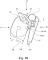
- a spacing mechanism between the photosensitive drum 1 and the developing roller 25 will be described with reference to Figures 9 and 10 .
- the apparatus main assembly is provided with a spacing member 94 at a predetermined position with respect to a longitudinal direction of the process cartridge 70.
- a spacing force receiving portion 31a of the developing frame 31 receives a force from the spacing member 94 moving in an arrow N direction, thus moving the developing roller 25 to a spaced position where the developing roller 25 is spaced from the photosensitive drum 1.
- the developing unit 4 when the spacing member 94 moves in an arrow P direction away from the spacing force receiving portion 31a, the developing unit 4 is rotated in an arrow T direction about the holes 12a and 13a of the front and rear developing bearings 12 and 13 by the urging force of the urging springs 32 ( Figure 5 ) provided at the ends of the developing frame 31. Then, the developing unit 4 is moved to a contact position, so that the developing roller 25 and the photosensitive drum 1 are in contact with each other. At least during the image formation, the developing unit 4 is held at a contact position of Figure 9 . Then, at timing, set in advance, such as during stand-by other than during image formation, the developing unit 4 is held at the spaced position of Figure 9 . By that, an effect of suppressing the influence of deformation of the developing roller 25 on an image quality is obtained.
- the developing unit 4 When the process cartridge 70 is mounted in the apparatus main assembly 100A, the developing unit 4 is in the contact portion, and the photosensitive drum 1 and the developing roller 25 are in contact with each other. At the time of completion of the mounting of the process cartridge 70 in the apparatus main assembly 100A and at the time of end of the image forming operation of the image forming apparatus 100, the developing unit 4 is in the spaced position, and the photosensitive drum 1 and the developing roller 25 are spaced from each other.
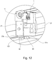
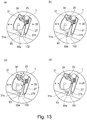
- the apparatus main assembly 100A is provided with an image forming apparatus opening 101 for permitting mounting of the process cartridge 70. Further, as shown in Figures 11 and 12 , the apparatus main assembly 100A is provided with a spacing guide portion 93 contacting a spacing force receiving portion 31a provided on the developing unit 4 of the process cartridge 70.
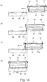
- the developing unit 4 rotates in an arrow J direction about a rear supporting pin 15 as a rotation center. Then, the developing unit 4 moves in an arrow K direction to the spaced position. Then, when the process cartridge 70 is positioned in the apparatus main assembly 100A, as shown in (d) of Figure 13 and (d) of Figure 14 , the spacing force receiving portion 31a is in a contact state with the spacing member 94 disposed downstream of the spacing guide portion 93 with respect to the mounting direction. At that time, the developing unit 4 is in the spaced position, so that the process cartridge 70 can be mounted in the apparatus main assembly 100A while keeping the developing roller 25 in the spaced state from the photosensitive drum 1.
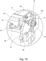
- Figure 15 is an illustration showing a longitudinal one end side (rear side) of a supporting portion for the developing roller 25 and the developer supplying roller 34.
- a developing roller shaft 25j of the developing roller 25 and a developer supplying roller shaft 34j of the developer supplying roller 34 are rotatably engaged with an inner peripheral surface of the rear developing bearing 13.
- the supporting constitution in the longitudinal one end side of the developing roller 25 and the developer supplying roller 34 was described, but also in the other longitudinal one end side, similarly, the bearing portion is integrally provided with the bearing member, and the developing roller shaft 25j and the developer supplying roller shaft 34j are rotatably engaged in the other end side.
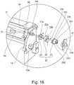
- an Oldham coupling 20 which is a shaft coupling member is used.
- the Oldham coupling 20 is constituted by a follower-side engaging portion 21 which is a driven portion, an intermediary engaging portion which is an intermediary portion, and a driving-side engaging portion 23 which is a drive receiving portion.
- the follower-side engaging portion 21 is fixed and mounted to an end portion (in one end side with respect to an axial direction) of the developer supplying roller shaft 34j.
- a fixing method there are a method in which connection is made by a spring pin or a parallel pin and a method in which as shown in Figure 16 , the developer supplying roller shaft 34j is provided with a cut portion 34k at an end surface thereof and also a hole in the follower-side engaging portion 21 side is similarly shape and is engaged with the cut portion 34k.
- the driving-side engaging portion 23 (first drive receiving portion) is a portion for receiving a driving force of a driving source of the main assembly. Further, in this embodiment, an H direction and an I direction are in a substantially perpendicular relationship. A shaft portion 23d of the driving-side engaging portion 23 is rotatably held in a hole 41d of a holding portion 41. Further, the driving-side engaging portion 23 is integrally formed with three projections 23c1, 23c2 and 23c3 engageable with a main assembly(-side) developing (means) coupling 91 ( Figure 18 ) which is a second main assembly(-side) drive transmitting member of the 100A described later.
- This Oldham coupling 20 allows a deviation between an axis of the main assembly developing coupling 91 and an axis of the developer supplying roller 34, and transmits a rotational driving force (first rotational driving force) from the apparatus main assembly 100A to the developer supplying roller 34. Further, the Oldham coupling 20 is capable of transmitting a rotational driving force (second rotational driving force) from the apparatus main assembly 100A to the developer supplying roller 34 in a state in which the developing unit 4 is in the contact position and in the spaced position.
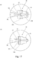
- Figure 17 a constitution of the Oldham coupling 20 will be described in further detail using sectional views.
- Figure 17(a) is a sectional view of the Oldham coupling 20 cut in an arrow H direction in Figure 16
- Figure 17(b) is a schematic view of the Oldham coupling 20 cut in an arrow I direction in Figure 16 .
- the follower-side engaging portion 21 is integrally provided with a rib 21a.
- the intermediary engaging portion 22 is provided with a groove 22a, and the rib 21a and the groove 22a are engaged with each other so as to be movable in the arrow H direction of Figure 16 .
- the driving-side engaging portion 23 is integrally provided with a rib 23b.
- the intermediary engaging portion 22 is provided with a groove 22b, and the rib 23b and the groove 22b are engaged with each other so as to be movable in the arrow I direction of Figure 16 .
- the H direction and the I direction are in the substantially perpendicular relationship.
- the intermediary engaging portion 22 engages with the follower-side engaging portion 21 and the driving-side engaging portion 23, and constitutes an intermediary portion for transmitting a driving force, inputted into the driving-side engaging portion 23, to the follower-side engaging portion 21, and is movable in a direction crossing the axial direction of the developer supplying roller 34 while maintaining engagement with each of the engaging portions 21 and 23.
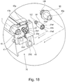
- Figure 18 is an illustration showing a constitution including the coupling provided on the process cartridge 70 and the coupling provided in the apparatus main assembly 100A.
- the three projections 23c1, 23c2 and 23c3 projecting in the axial direction are formed.
- a centering boss 23a for being aligned with the axis (rotation enter) of the main assembly developing coupling 91 projects in the axial direction from the end surface of the driving-side engaging portion 23.
- the photosensitive drum 1 is provided, in one end side with respect to the axial direction, with a triangular prism drum coupling 16.
- a guide portion 41b of the holding portion 41 is movable, in a direction crossing the axial direction of the developer supplying roller 34, along the groove 43a of the side cover 43 fixed on the developing unit with an unshown screw or the like. That is, the driving-side engaging portion 23 is movable in a direction (the direction crossing the axial direction of the developer supplying roller) crossing the developing unit 4.
- the main assembly drum coupling 90 which is a first main assembly drive transmitting member for transmitting the drive of the apparatus main assembly 100A to the photosensitive drum 1 is provided with a hole 90a having a substantially triangular shape in cross section.
- the main assembly developing coupling 91 which is a second main assembly drive transmitting member for transmitting the rotational driving force (second rotational driving force) from the apparatus main assembly 100A to the developer supplying roller 34 is provided with three holes 91a1, 91a2 and 91a3.
- the main assembly drum coupling 90 is urged in a direction of the process cartridge 70 by a drum pressing (urging) member 106 such as a compression spring. Further, the main assembly drum coupling 90 is movable in the axial direction of the photosensitive drum 1. Further, in the case where the drum coupling 16 and the hole 90a of the main assembly drum coupling 90 are out of phase and in contact with each other when the process cartridge 70 is mounted in the apparatus main assembly 100A, the main assembly drum coupling 90 is pushed by the drum coupling 16, thus being retracted. Then by rotation of the main assembly drum coupling 90, the drum coupling 16 and the hole 90a are engaged with each other, the rotational driving force is transmitted to the photosensitive drum 1.
- a drum pressing (urging) member 106 such as a compression spring.
- the main assembly developing coupling 91 is urged in the direction of the process cartridge 70 toward a direction parallel to the axial direction of the photosensitive drum 1 by a developing (means) pressing (urging) member 107 such as a compression spring.
- a developing (means) pressing (urging) member 107 such as a compression spring.
- the main assembly developing coupling 91 has no play with respect to the direction crossing the axial direction and is provided in the apparatus main assembly 100A. That is, the main assembly developing coupling 91 not only rotates for transmitting the drive (driving force) but also in movable only in the axial direction.
- the projections 23c1 - 23c3 and the holes 91a1 - 91a3 are out of phase in some cases.
- free ends of the projections 23c1 - 23c3 contact portions other than the holes 91a1 - 91a3, so that the main assembly developing coupling 91 is retracted in the axial direction against an urging force of the developing pressing member 107.
- the main assembly developing coupling 91 rotates and the projections 23c1 - 23c3 and the holes 91a1 - 91a3 are in phase, the main assembly developing coupling 91a advances by the urging force of the developing pressing member 107.
- the projections 23c1 - 23c3 and the holes 91a1 - 91a3 engage with each other, and also the centering boss 23a which is an engaging portion positioning portion and the centering hole 91b which is a transmitting member positioning portion engage with each other, so that the driving-side engaging portion 23 and the axis (rotation center) of the main assembly developing coupling 91 coincide with each other.
- the projections 23c1 - 23c3 and the holes 91a1 - 91a3 engage with each other, respectively, so that the rotational driving force is transmitted to the developer supplying roller 34.
- rotation of the developing roller 25 will be described.
- the developer supplying roller 34 is provided with the driving-side engaging portion 23 in one end side and is provided with a gear in the other end side with respect to the longitudinal direction (the axial direction of the developer supplying roller).
- the developing roller 25 is provided with a gear engageable with the above gear.
- the drive transmission to the main assembly drum coupling 90 and the main assembly developing coupling 91 is made by a motor provided in the apparatus main assembly 100A.
- the motor may employ a constitution using a single motor per each of the process cartridges 70 for the respective colors and a constitution in which the drive is transmitted to some process cartridges by the single motor.
- Figure 1 is an illustration showing a driving force inputting portion and a driving system of the developing unit in this embodiment.
- Figure 3 is an illustration showing the cartridge mounted in the image forming apparatus.
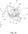
- Figure 19 is an illustration showing a constitution of the developing chamber in this embodiment.
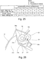
- Figure 26 is an illustration showing a comparison example in which the developing chamber toner feeding member is provided in the developing chamber.
- the toner accommodating portion 31c of the developing frame 31 is provided with the toner feeding member 36 ( Figure 3 ) for not only stirring the accommodated toner but also feeding the toner to the developing chamber 31b via the toner opening 31e.
- the toner feeding member 36 Figure 3
- the toner accommodating portion 31c is provided below the developing chamber 31b with respect to direction of gravity, and therefore the toner feeding member 36 is positioned below the developing chamber 31b with respect to the direction of gravity.
- the process cartridge 70 in this embodiment has a scooping-up constitution in which the toner is fed by the toner feeding member 36 against the gravity from the toner accommodating portion 31c disposed below the developing chamber 31b with respect to the direction of gravity to the developing chamber 31b disposed above the toner accommodating portion 31c with respect to the direction of gravity.
- the developer fed from the toner accommodating portion 31c to the developing chamber 31b stagnates at a developing chamber bottom (portion) 31f as shown in Figure 19 .
- a developing chamber toner feeding member 37 is provided at the developing chamber bottom 31f, and the a developing chamber toner feeding member 37 is moved, so that the developer stagnating at the developing chamber 31f was supplied to the developer supplying roller 34.
- the developer supplying roller 34 is set so as to rotate in a direction (arrow E direction) opposite to the rotational direction (arrow B direction) of the developer supplying roller 34. That is, at the contact portion between the developing roller 25 and the developer supplying roller 34, the respective surfaces thereof are in a direction of movement in the same direction.
- the rotational direction of the photosensitive drum 1 is an opposite direction to the rotational direction of the developing roller. Further, the rotational direction of the photosensitive drum 1 is the same direction as the rotational direction of the developer supplying roller 34.
- the developer supplying roller 34 has a constitution in which a sponge portion (elastic layer having an inner porous portion) 34a is provided. Further, in Figure 19 , the developing roller 25 has an elastic layer 25a. A surface hardness of the developer supplying roller 34 is lower than a surface hardness of the developing roller 25, and therefore when both rollers are in contact with each other, as shown in Figure 19 , the developer supplying roller is dented (deformed).
- the developer supplying roller 34 is in a state in which the surface of the sponge portion 34a is deformed correspondingly to a penetration amount at the contact portion with the developing roller 25. At this time, from the sponge portion 34a, the toner contained in the sponge portion 34a is discharged.
- This discharging portion 34b is a region in a side upstream of the contact portion between the developer supplying roller 34 and the developing roller 25 with respect to the rotational direction of the developer supplying roller 34.
- a taking-in portion 34c is a region in a side downstream of the contact portion between the developer supplying roller 34 and the developing roller 25 with respect to the rotational direction of the developer supplying roller 34. The toner taken in this region is discharged again at the discharging portion 34b.
- the toner is circulated by continuously performing the above-described taking-in and discharging, and in this process, supply of the developer to the developing roller 25 is made.
- the rotational direction (arrow C direction) of the developer supplying roller 34 in the comparison example is set at the same direction as the rotational direction (arrow B direction) of the developing roller 25 in many cases.
- the taking-in portion 34c is positioned above the developing roller 25 and the developer supplying roller 34. Accordingly, in order to stably supply the toner to the taking-in portion 34c, there is a need to provide such an arrangement relationship that the toner which passes through the toner opening 31e and which moves toward the taking-in portion 34c positioned above the developer supplying roller 34 is not blocked by the developer supplying roller 34 itself.
- the developing chamber toner feeding member 37 which is a stirring member is provided, and there was a need to supply the toner to the developer supplying roller 34 by the developing chamber toner feeding member 37.
- the taking in portion 34c is positioned below the developing roller 25 and the developer supplying roller 34 and is close to the bottom 31f of the developing chamber 31b. That is, the toner fed to the developing chamber 31b moves toward the rear portion by the airflow generated at the taking-in portion 31c, so that the taking-in portion is located at a position where the toner easily reaches the taking-in portion 31c naturally. Accordingly, constraint of an arrangement relationship between the toner opening 31e and the developer supplying roller 34 as in the conventional constitution is alleviated, and therefore a degree of flexibility in design of the arrangement of the toner opening 31e and the developer supplying roller 34 becomes high.
- the toner surface in the developing chamber 31b always reaches a height of the taking-in portion 34c, and therefore a toner supplying property to the developing chamber 31c is further stabilized.
- the height of the lower end 31e2 of the toner opening 31e is disposed at a position higher than a downstream end of the contact portion between the developer supplying roller 34 and the developing roller 25 with respect to the rotational direction of the developer supplying roller 34. Further, the taking-in portion 34c is positioned close to the bottom 31f of the developing chamber 31b, and therefore the toner accumulated at the bottom 31 is naturally taken in the developer supplying roller 34 and is gradually consumed.
- the circulation of the toner is made even when the developing chamber toner feeding member 37 shown in Figure 26 is not used, and therefore a space in which the developing chamber toner feeding member 37 has been conventionally disposed can be filled, so that it is possible to reduce the residual toner.
- the surface speed of the developer supplying roller 34 is higher than the surface speed of the developing roller 25, so that a portion, where the toner is contained in a sufficient amount, of the sponge portion 34a always contacts the developing roller 25, and therefore stable toner supply to the developing roller 25 can be effected. Further, with respect to the toner peeling-off property, the surface speed of the developer supplying roller 34 is higher than the surface speed of the developing roller 25 and therefore a frictional force due to a peripheral speed driving force generates, so that the toner on the developing roller 25, which is not used for development, can be peeled off.
- the diameter 34r of the sponge portion 34a may desirably be large, and in this embodiment, a diameter 25r of the developing roller 25 is set at 12 mm and the diameter 34r of the developer supplying roller 34 is set at 13.3 mm, so that a diameter ratio therebetween is about 1.11.
- a diameter ratio therebetween is about 1.11
- a surface speed ratio between the developing roller 25 and the developer supplying roller 34 i.e., (developer supplying roller surface speed)/(developing roller surface speed), hereinafter referred to as a "peripheral speed ratio”
- the peripheral speed ratio is set in a range of 1.3 or more and 1.8 or less. This set range is such a range that necessary and sufficient toner supplying property and toner peeling off property can be maintained.
- the peripheral speed ratio is below 1.3, there is a liability that a good toner peeling-off property cannot be maintained, so that there is a liability of the influence of a ghost or the like on an image quality.
- the peripheral speed ratio is 1.8 or less, the toner supplying property and the toner peeling-off property can be sufficiently maintained. For that reason, when the peripheral speed ratio exceeds 1.8, friction becomes large and thus abrasion of the developer supplying roller and the developing roller is liable to generate, and therefore it is not desirable that the surface speed of the developer supplying roller 34 is excessively increased.
- the surface speed of the developing roller 25 is set at about 304 mm/s and the surface speed of the developer supplying roller 34 is set at about 487 mm/s, so that the peripheral speed ratio therebetween is about 1.60.
- the surface speed referred herein is a speed on the surface excluding the contact portion between the developing roller 25 and the developer supplying roller 34, and this is similarly applicable to also the peripheral speed ratio.
- Figure 1 is an illustration showing the driving system for the developing unit 4, and for simplification of explanation, only the developing roller 25, the developer supplying roller 34 and the driving system relating to these rollers are extracted and shown.
- the shaft portion 34j of the developer supplying roller 34 is provided with the developer supplying roller gear 38 which is an upstream drive transmitting member (first drive transmitting portion).
- the shaft portion 25j of the developing roller 25 is provided with the developing roller gear 39 which is a downstream drive transmitting member (second drive transmitting portion) provided so as to directly engage with the developer supplying roller gear 38.
- a gear train such as the developer supplying roller gear 38 is provided in a side (the other side) opposite from the driving force inputting portion of the developing unit 4 with respect to the axial direction from the viewpoint of the space or the like, but the gear train and the driving force inputting portion may also be provided in the same side.
- the rotational directions of the developing roller 25 and the developer supplying roller 34 are opposite to each other, and therefore there is no need to provide an idler gear between the developer supplying roller gear 38 and the developing roller gear 39, so that the number of parts can be reduce.
- the driving force inputted onto the shaft of the developer supplying roller 34 is transmitted from the developer supplying roller gear 38 to the developing roller 25 via the developing roller gear 39.
- the number of teeth of the developer supplying roller gear 38 is set at 18 teeth
- the number of teeth of the developing roller gear 39 is set at 26 teeth.
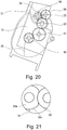
- Figure 20 is an illustration showing the driving system in a side downstream of the developing roller 25.
- a developing (means) idler gear 80, a stirring idler gear 81 and a stirring gear 82 which are used for transmitting the drive to the toner feeding member 36 are provided in the listed order.
- the developing idler gear 80 and the stirring idler gear 81 are rotatably supported by the front developing bearing 12, and the stirring gear 82 is rotatably supported by the developing frame 31 in a state in which the stirring gear 82 is connected to the toner feeding member 36 by an unshown connecting means such as snap-fit means and an engaging portion.
- the driving force inputted onto the shaft of the developer supplying roller 34 is transmitted in the order of the developer supplying roller gear 38, the developing roller gear 39, the developing idler gear 80, the stirring idler gear 81 and the stirring gear 82 and is finally transmitted to the toner feeding member 36.
- Figure 22 is an illustration showing a constitution in which different from this embodiment, the driving force from the main assembly is not inputted into the developer supplying roller 34, but is inputted into the developing roller 25.
- the developing roller gear 39 drive the developer supplying roller gear 38.
- Figure 23 is an illustration showing one tooth of each of the developer supplying roller gear and the developing roller gear at an engaging portion between a tooth 38a of the developer supplying roller gear and a tooth 39a of the developing roller gear.
- Figure 23(a) is an illustration showing a state in which the sponge portion 34a which is not deformed reaches the contact position with the developing roller 25
- Figure 23(b) is an illustration showing a state in which the small deformation portion 34n reaches the contact position with the developing roller 25.
- a broken line 39b shown in (b) of Figure 23 represents a behavior of the developing roller gear tooth 39a in a state in which a load from the developer supplying roller gear 38 is decreased.
- the rotational speed of the developing roller 25 instantaneously increased. Therefore, the surface speed of the driving-side 25 instantaneously increases relative to the surface speed of the photosensitive drum 1, and therefore there is a possibility that non-uniformity generates in toner supplying property from the developing roller 25 to the photosensitive drum 1 and thus a phenomenon such as a lateral stripe generates on the image. Incidentally, it is known that this phenomenon is liable to generate as the peripheral speed difference between the surface speed of the developing roller 25 and the surface speed of the developer supplying roller 34 becomes larger.
- the developer supplying roller 34 is in a state in which the developer supplying roller 34 readily rotates instantaneously by passing of the small deformation portion 34n of the developer supplying roller 34 through the contact portion with the developing roller 25.
- the small deformation generates at the sponge portion 34a of the developer supplying roller 34, the non-uniformity does not readily generate in toner supplying property from the developing roller 25 to the photosensitive drum 1.
- the constitution in which the driving force in inputted into the developer supplying roller 34 is capable of suppressing a lowering in image quality compared with a constitution in which the driving force is inputted into the developing roller 25.
- the rotational direction (arrow C direction) of the developer supplying roller 34 is made the opposite direction to the rotational direction (arrow B direction) of the developing roller.
- the surface speed of the developer supplying roller 34 is set so as to be higher than the surface speed of the developing roller, whereby it becomes possible to stably supply the toner to the developing roller.
- the driving force from the image forming apparatus main assembly is inputted onto the shaft of the developer supplying roller 34, whereby it is possible to reduce an image defect generating, e.g., when the developer supplying roller 34 is left standing in the high-temperature environment or the like.
- the developing device having the scooping constitution including the toner accommodating chamber below the developing chamber 31c it is possible to provide a process cartridge and an image forming apparatus which are capable of improving the image quality while reducing the number of parts and decreasing the amount of the residual toner.
- a process cartridge and an image forming apparatus which are capable of realizing reduction of a residual developer while reducing the number of parts, in a constitution that a developer is scooped up from a developer accommodating chamber, provided below a developing chamber, to the developing chamber above the developer accommodating chamber.
Landscapes
- Physics & Mathematics (AREA)
- General Physics & Mathematics (AREA)
- Engineering & Computer Science (AREA)
- Computer Vision & Pattern Recognition (AREA)
- Health & Medical Sciences (AREA)
- Toxicology (AREA)
- Electrophotography Configuration And Component (AREA)
- Dry Development In Electrophotography (AREA)
Claims (13)
- Cartouche de traitement, comprenant :(i) un tambour photosensible (1) ;(ii) un rouleau de développement mobile en rotation (25) destiné à développer une image latente électrostatique formée sur ledit tambour photosensible (1) ;(iii) un rouleau d'alimentation en développateur (34), disposé en contact avec ledit rouleau de développement (25), destiné à alimenter ledit rouleau de développement (25) en développateur, le rouleau d'alimentation en développateur comprenant un axe (34j) ;(iv) une partie de réception de force d'entraînement (23) destinée à recevoir une force d'entraînement pour entraîner en rotation ledit rouleau d'alimentation en développateur (34) et ledit rouleau de développement (25), dans laquelle ladite partie de réception de force d'entraînement (23) est disposée au niveau d'une partie d'extrémité d'axe dudit rouleau d'alimentation en développateur (34) ;(v) une première partie de transmission de force d'entraînement (38) destinée à transmettre la force d'entraînement, reçue par ladite partie de réception de force d'entraînement (23), audit rouleau de développement (25) ; et(vi) une seconde partie de transmission de force d'entraînement (39), disposée au niveau d'une partie d'extrémité axiale dudit rouleau de développement (25), destinée à transmettre la force d'entraînement de ladite première partie de transmission de force d'entraînement (38) audit rouleau de développement (25) par coopération avec ladite première partie de transmission de force d'entraînement (38),caractérisée en ce que
ladite partie de réception de force d'entraînement (23) est mobile par rapport audit rouleau d'alimentation en développateur (34) dans une direction perpendiculaire à l'axe (34j) dudit rouleau d'alimentation en développateur (34),
ladite première partie de transmission de force d'entraînement (38) est disposée au niveau d'une partie d'extrémité axiale dudit rouleau d'alimentation en développateur (34), et
ladite cartouche de traitement (70) est conçue de sorte qu'un sens de rotation dudit rouleau de développement (25) soit un sens contraire à un sens de rotation dudit rouleau d'alimentation en développateur (34) de façon à mettre en mouvement des surfaces dudit rouleau de développement (25) et dudit rouleau d'alimentation en développateur (34) dans le même sens au niveau d'une partie de contact entre ledit rouleau de développement (25) et ledit rouleau d'alimentation en développateur (34), et qu'une vitesse de surface dudit rouleau d'alimentation en développateur (34) soit supérieure à une vitesse de surface dudit rouleau de développement (25) lorsque ledit rouleau d'alimentation en développateur (34) et ledit rouleau de développement (25) sont entraînés en rotation. - Cartouche de traitement (70) selon la revendication 1, dans laquelle un diamètre extérieur (34r) dudit rouleau d'alimentation en développateur (34) est supérieur à un diamètre extérieur (25r) dudit rouleau de développement (25) .
- Cartouche de traitement (70) selon la revendication 1 ou 2, dans laquelle chaque partie de ladite première partie de transmission de force d'entraînement (38) et de ladite seconde partie de transmission de force d'entraînement (39) est une roue dentée (38, 39), et le nombre de dents de ladite seconde partie de transmission de force d'entraînement (39) est supérieur au nombre de dents de ladite première partie de transmission de force d'entraînement (38).
- Cartouche de traitement (70) selon l'une quelconque des revendications 1 à 3, dans laquelle un rapport de vitesses périphériques dudit rouleau d'alimentation en développateur (34) audit rouleau de développement (25) est :

- Cartouche de traitement (70) selon l'une quelconque des revendications 1 à 4, dans laquelle ledit rouleau d'alimentation en développateur (34) est un rouleau (34) comprenant une couche élastique (34a).
- Cartouche de traitement (70) selon l'une quelconque des revendications 1 à 5, comprenant en outre un moyen de distribution (36) destiné à distribuer une encre en poudre, et la force d'entraînement est transmise de ladite seconde partie de transmission de force d'entraînement (39) audit moyen de distribution (36).
- Cartouche de traitement (70) selon l'une quelconque des revendications 1 à 6, dans laquelle ladite partie de réception de force d'entraînement (23) reçoit la force d'entraînement d'une partie extérieure de ladite cartouche de traitement (70).
- Appareil de formation d'image (100) comprenant un ensemble principal (100A) et une cartouche de traitement (70), dans lequel :(i) ledit ensemble principal (100A) comprend (i-i) une partie d'entraînement ; et(ii) ladite cartouche de traitement (70) peut être montée de manière amovible sur ledit appareil de formation d'image, et ladite cartouche de traitement (100) comprend :caractérisé en ce que(ii-i) un tambour photosensible (1) ;(ii-ii) un rouleau de développement mobile en rotation (25) destiné à développer une image latente électrostatique formée sur ledit tambour photosensible (1) ;(ii-iii) un rouleau d'alimentation en développateur (34), disposé en contact avec ledit rouleau de développement (25), destiné à alimenter ledit rouleau de développement (25) en développateur, ledit rouleau d'alimentation en développateur comprenant un axe (34j) ;(ii-iv) une partie de réception de force d'entraînement (23) destinée à recevoir une force d'entraînement pour entraîner en rotation ledit rouleau d'alimentation en développateur (34) et ledit rouleau de développement (25), dans lequel ladite partie de réception de force d'entraînement (23) est disposée au niveau d'une partie d'extrémité d'axe dudit rouleau d'alimentation en développateur (34) ;(ii-v) une première partie de transmission de force d'entraînement (38) destinée à transmettre la force d'entraînement, reçue par ladite partie de réception de force d'entraînement (23), audit rouleau de développement (25) ; et(ii-vi) une seconde partie de transmission de force d'entraînement (39), disposée au niveau d'une partie d'extrémité axiale dudit rouleau de développement (25), destinée à transmettre la force d'entraînement de ladite première partie de transmission de force d'entraînement (38) audit rouleau de développement (25) par une coopération avec ladite première partie de transmission de force d'entraînement (38),
ladite partie de réception de force d'entraînement (23) reçoit la force d'entraînement en se trouvant en prise avec ladite partie d'entraînement,
ladite partie de réception de force d'entraînement (23) est mobile par rapport audit rouleau d'alimentation en développateur (34) dans une direction perpendiculaire à l'axe (34j) dudit rouleau d'alimentation en développateur (34),
ladite première partie de transmission de force d'entraînement (38) est disposée au niveau d'une partie d'extrémité axiale dudit rouleau d'alimentation en développateur (34), et
ladite cartouche de traitement (70) est conçue de sorte qu'un sens de rotation dudit rouleau de développement (25) soit un sens contraire à un sens de rotation dudit rouleau d'alimentation en développateur (34), de façon à mettre en mouvement des surfaces dudit rouleau de développement (25) et dudit rouleau d'alimentation en développateur (34) dans le même sens au niveau d'une partie de contact située entre ledit rouleau de développement (25) et ledit rouleau d'alimentation en développateur (34), et qu'une vitesse de surface dudit rouleau d'alimentation en développateur (34) soit supérieure à une vitesse de surface dudit rouleau de développement (25) lorsque ledit rouleau d'alimentation en développateur (34) et ledit rouleau de développement (25) sont entraînés en rotation. - Appareil de formation d'image (100) selon la revendication 8, dans lequel un diamètre extérieur (34r) dudit rouleau d'alimentation en développateur (34) est supérieur à un diamètre extérieur (25r) dudit rouleau de développement (25).
- Appareil de formation d'image (100) selon la revendication 8 ou la revendication 9, dans lequel chaque partie de ladite première partie de transmission de force d'entraînement (38) et de ladite seconde partie de transmission de force d'entraînement (39) est une roue dentée (38, 39), et le nombre de dents de ladite seconde partie de transmission de force d'entraînement (39) est supérieur au nombre de dents de ladite première partie de transmission de force d'entraînement (38).
- Appareil de formation d'image (100) selon l'une quelconque des revendications 8 à 10, dans lequel un rapport de vitesses périphériques dudit rouleau d'alimentation en développateur (34) audit rouleau de développement (25) est :

- Appareil de formation d'image (100) selon l'une quelconque des revendications 8 à 11, dans lequel, lorsque ladite cartouche de traitement (70) est montée dans ledit appareil de formation d'image (100), ladite cartouche de traitement (70) comprend une partie de réception (31) destinée à recevoir une encre en poudre, située sous ledit rouleau d'alimentation en développateur (34) par rapport au sens de la gravité.
- Appareil de formation d'image (100) selon l'une quelconque des revendications 8 à 12, comprenant en outre un moyen de distribution (36) destiné à distribuer une encre en poudre dans ladite partie de réception (31) en direction dudit rouleau d'alimentation en développateur (34), et la force d'entraînement est transmise de ladite seconde partie de transmission de force d'entraînement (39) audit moyen de distribution (36).
Priority Applications (8)
| Application Number | Priority Date | Filing Date | Title |
|---|---|---|---|
| EP19207356.7A EP3637192B1 (fr) | 2012-12-14 | 2013-12-13 | Cartouche de traitement |
| MEP-2019-206A ME03492B (fr) | 2012-12-14 | 2013-12-13 | Cartouche de traitement et dispositif de formation d'image |
| DK18166572.0T DK3379339T3 (da) | 2012-12-14 | 2013-12-13 | Procespatron og billeddannende indretning |
| PL18166572T PL3379339T3 (pl) | 2012-12-14 | 2013-12-13 | Kartridż procesowy oraz urządzenie tworzące obraz |
| EP18166572.0A EP3379339B1 (fr) | 2012-12-14 | 2013-12-13 | Cartouche de traitement et appareil de formation d'images |
| RS20190927A RS59023B1 (sr) | 2012-12-14 | 2013-12-13 | Procesni kertridž i uređaj za formiranje slike |
| EP22171733.3A EP4075203A1 (fr) | 2012-12-14 | 2013-12-13 | Cartouche de traitement et appareil de formation d'images |
| PL13862540T PL2933685T3 (pl) | 2012-12-14 | 2013-12-13 | Kartridż procesowy oraz urządzenie tworzące obraz |
Applications Claiming Priority (2)
| Application Number | Priority Date | Filing Date | Title |
|---|---|---|---|
| JP2012273204 | 2012-12-14 | ||
| PCT/JP2013/084174 WO2014092208A1 (fr) | 2012-12-14 | 2013-12-13 | Cartouche de traitement et dispositif de formation d'image |
Related Child Applications (4)
| Application Number | Title | Priority Date | Filing Date |
|---|---|---|---|
| EP19207356.7A Division EP3637192B1 (fr) | 2012-12-14 | 2013-12-13 | Cartouche de traitement |
| EP18166572.0A Division EP3379339B1 (fr) | 2012-12-14 | 2013-12-13 | Cartouche de traitement et appareil de formation d'images |
| EP18166572.0A Division-Into EP3379339B1 (fr) | 2012-12-14 | 2013-12-13 | Cartouche de traitement et appareil de formation d'images |
| EP22171733.3A Division EP4075203A1 (fr) | 2012-12-14 | 2013-12-13 | Cartouche de traitement et appareil de formation d'images |
Publications (3)
| Publication Number | Publication Date |
|---|---|
| EP2933685A1 EP2933685A1 (fr) | 2015-10-21 |
| EP2933685A4 EP2933685A4 (fr) | 2016-07-20 |
| EP2933685B1 true EP2933685B1 (fr) | 2019-05-08 |
Family
ID=50934485
Family Applications (4)
| Application Number | Title | Priority Date | Filing Date |
|---|---|---|---|
| EP18166572.0A Active EP3379339B1 (fr) | 2012-12-14 | 2013-12-13 | Cartouche de traitement et appareil de formation d'images |
| EP19207356.7A Active EP3637192B1 (fr) | 2012-12-14 | 2013-12-13 | Cartouche de traitement |
| EP22171733.3A Pending EP4075203A1 (fr) | 2012-12-14 | 2013-12-13 | Cartouche de traitement et appareil de formation d'images |
| EP13862540.5A Active EP2933685B1 (fr) | 2012-12-14 | 2013-12-13 | Cartouche de traitement et dispositif de formation d'image |
Family Applications Before (3)
| Application Number | Title | Priority Date | Filing Date |
|---|---|---|---|
| EP18166572.0A Active EP3379339B1 (fr) | 2012-12-14 | 2013-12-13 | Cartouche de traitement et appareil de formation d'images |
| EP19207356.7A Active EP3637192B1 (fr) | 2012-12-14 | 2013-12-13 | Cartouche de traitement |
| EP22171733.3A Pending EP4075203A1 (fr) | 2012-12-14 | 2013-12-13 | Cartouche de traitement et appareil de formation d'images |
Country Status (17)
| Country | Link |
|---|---|
| US (1) | US9519264B2 (fr) |
| EP (4) | EP3379339B1 (fr) |
| JP (4) | JP6242201B2 (fr) |
| CN (4) | CN111240171B (fr) |
| BR (1) | BR112015013940B1 (fr) |
| CA (2) | CA3187234A1 (fr) |
| DK (2) | DK2933685T3 (fr) |
| ES (2) | ES2729326T3 (fr) |
| HK (1) | HK1209851A1 (fr) |
| HU (2) | HUE051177T2 (fr) |
| ME (1) | ME03492B (fr) |
| PL (2) | PL2933685T3 (fr) |
| PT (2) | PT2933685T (fr) |
| RS (2) | RS60974B1 (fr) |
| RU (8) | RU2608318C1 (fr) |
| TR (1) | TR201911114T4 (fr) |
| WO (1) | WO2014092208A1 (fr) |
Families Citing this family (16)
| Publication number | Priority date | Publication date | Assignee | Title |
|---|---|---|---|---|
| JP6242201B2 (ja) | 2012-12-14 | 2017-12-06 | キヤノン株式会社 | プロセスカートリッジ及び画像形成装置 |
| US10025266B2 (en) | 2012-12-14 | 2018-07-17 | Canon Kabushiki Kaisha | Process cartridge including a coupling member and a sheet that contacts the coupling member |
| JP6376749B2 (ja) | 2013-12-06 | 2018-08-22 | キヤノン株式会社 | プロセスカートリッジおよび電子写真画像形成装置 |
| JP6134689B2 (ja) * | 2014-06-03 | 2017-05-24 | 京セラドキュメントソリューションズ株式会社 | 像担持体ユニット及びこれを備えた画像形成装置 |
| JP6494304B2 (ja) * | 2015-01-26 | 2019-04-03 | キヤノン株式会社 | ギアユニット、現像装置及びその製造方法 |
| JP6486148B2 (ja) * | 2015-02-27 | 2019-03-20 | キヤノン株式会社 | 画像形成装置およびカートリッジ |
| JP6570333B2 (ja) * | 2015-06-16 | 2019-09-04 | キヤノン株式会社 | 画像形成装置 |
| JP6583149B2 (ja) | 2016-06-08 | 2019-10-02 | 京セラドキュメントソリューションズ株式会社 | トナー容器、画像形成装置 |
| JP6914620B2 (ja) * | 2016-06-29 | 2021-08-04 | キヤノン株式会社 | 画像形成装置 |
| MX2019002146A (es) | 2016-08-26 | 2019-07-04 | Canon Kk | Unidad de tambor, cartucho, aparato de formacion de imagenes electrofotograficas y miembro de acoplamiento. |
| AU2016420865B2 (en) * | 2016-08-26 | 2020-07-02 | Canon Kabushiki Kaisha | Drum unit, cartridge, electrophotographic image forming apparatus and coupling member |
| CN107918267A (zh) * | 2016-10-09 | 2018-04-17 | 江西亿铂电子科技有限公司 | 一种处理盒 |
| JP2018169536A (ja) * | 2017-03-30 | 2018-11-01 | ブラザー工業株式会社 | 現像カートリッジ |
| JP7331195B2 (ja) * | 2017-08-30 | 2023-08-22 | キヤノン株式会社 | 現像装置 |
| JP7066356B2 (ja) | 2017-08-30 | 2022-05-13 | キヤノン株式会社 | 現像装置 |
| CN110609459B (zh) * | 2019-09-27 | 2024-07-09 | 珠海联合天润打印耗材有限公司 | 处理盒 |
Family Cites Families (71)
| Publication number | Priority date | Publication date | Assignee | Title |
|---|---|---|---|---|
| JP3020597B2 (ja) * | 1990-11-16 | 2000-03-15 | 株式会社リコー | 電子写真装置 |
| JPH063934A (ja) * | 1992-06-17 | 1994-01-14 | Tokyo Electric Co Ltd | 現像装置 |
| JPH06332285A (ja) * | 1993-05-25 | 1994-12-02 | Ricoh Co Ltd | 回転型現像装置 |
| JPH0869180A (ja) * | 1994-08-30 | 1996-03-12 | Nec Corp | 現像装置 |
| JP3347251B2 (ja) * | 1994-12-31 | 2002-11-20 | 株式会社リコー | 現像装置 |
| JPH0980890A (ja) * | 1995-09-13 | 1997-03-28 | Ricoh Co Ltd | 電子写真装置 |
| JP3387317B2 (ja) * | 1996-06-04 | 2003-03-17 | 富士ゼロックス株式会社 | 現像方法 |
| JPH10333409A (ja) | 1997-06-02 | 1998-12-18 | Ricoh Co Ltd | 現像装置 |
| JP3436697B2 (ja) * | 1998-10-13 | 2003-08-11 | シャープ株式会社 | 一成分トナーの現像装置 |
| JP3840072B2 (ja) * | 2001-07-31 | 2006-11-01 | キヤノン株式会社 | 現像装置 |
| JP2003084572A (ja) | 2001-09-14 | 2003-03-19 | Ricoh Co Ltd | 画像形成装置 |
| US6604814B2 (en) * | 2001-09-28 | 2003-08-12 | Hewlett-Packard Development Company, Lp | Arrangements of interconnect circuit and fluid drop generators |
| JP3595798B2 (ja) * | 2002-01-31 | 2004-12-02 | キヤノン株式会社 | プロセスカートリッジおよび電子写真画像形成装置 |
| JP3634807B2 (ja) | 2002-02-20 | 2005-03-30 | キヤノン株式会社 | プロセスカートリッジおよび画像形成装置 |
| JP3658372B2 (ja) | 2002-02-22 | 2005-06-08 | キヤノン株式会社 | プロセスカートリッジおよびプロセスカートリッジ用の離間保持部材 |
| EP1345089A1 (fr) * | 2002-03-13 | 2003-09-17 | Seiko Epson Corporation | Unité et dispositif de développement pour un appareil de formation d'images |
| JP4703951B2 (ja) * | 2002-07-12 | 2011-06-15 | 株式会社沖データ | 現像装置及び電子写真装置 |
| JP4374834B2 (ja) * | 2002-08-12 | 2009-12-02 | セイコーエプソン株式会社 | カートリッジおよび記録装置 |
| JP4230247B2 (ja) * | 2003-02-26 | 2009-02-25 | 京セラミタ株式会社 | 画像形成装置 |
| US7088939B2 (en) * | 2003-07-25 | 2006-08-08 | Canon Kabushiki Kaisha | Process cartridge and electrophotographic image forming apparatus |
| US7072603B2 (en) | 2003-08-01 | 2006-07-04 | Canon Kabushiki Kaisha | Process cartridge and holding member |
| JP3673793B2 (ja) | 2003-08-29 | 2005-07-20 | キヤノン株式会社 | プロセスカートリッジ、プロセスカートリッジの装着機構及び電子写真画像形成装置 |
| JP3970217B2 (ja) | 2003-08-29 | 2007-09-05 | キヤノン株式会社 | 電子写真画像形成装置 |
| JP4681833B2 (ja) | 2003-09-19 | 2011-05-11 | 株式会社リコー | 画像形成装置 |
| JP3673795B2 (ja) | 2003-10-24 | 2005-07-20 | キヤノン株式会社 | 現像装置、プロセスカートリッジ、及び、画像形成装置 |
| JP3782807B2 (ja) | 2003-11-28 | 2006-06-07 | キヤノン株式会社 | プロセスカートリッジ、及び電子写真感光体ドラムの取り付け方法 |
| JP3789122B2 (ja) | 2003-11-28 | 2006-06-21 | キヤノン株式会社 | プロセスカートリッジの再生産方法 |
| JP2005195883A (ja) * | 2004-01-07 | 2005-07-21 | Sharp Corp | 現像装置、及びそれを備える画像形成装置 |
| CN100394322C (zh) * | 2004-03-02 | 2008-06-11 | 精工爱普生株式会社 | 调色剂量的测定装置及测定方法、图像形成装置 |
| JP4600055B2 (ja) * | 2005-01-27 | 2010-12-15 | セイコーエプソン株式会社 | 現像装置、画像形成装置、画像形成システム、及び、現像剤供給ローラの組み付け方法 |
| JP4708853B2 (ja) * | 2005-05-12 | 2011-06-22 | キヤノン株式会社 | 現像装置及び画像形成装置 |
| US7664442B2 (en) * | 2006-05-30 | 2010-02-16 | Canon Kabushiki Kaisha | Developing apparatus |
| US8060003B2 (en) * | 2006-10-20 | 2011-11-15 | Canon Kabushiki Kaisha | Image forming apparatus wherein a setting unit sets an interval of image formation according to a size of a recording medium |
| JP4241865B2 (ja) * | 2006-12-08 | 2009-03-18 | キヤノン株式会社 | プロセスカートリッジ及び電子写真画像形成装置 |
| JP4841000B2 (ja) | 2006-12-11 | 2011-12-21 | キヤノン株式会社 | 現像剤容器、現像装置、及びプロセスカートリッジ |
| JP4651131B2 (ja) * | 2006-12-11 | 2011-03-16 | キヤノン株式会社 | プロセスカートリッジ |
| JP4464435B2 (ja) * | 2006-12-11 | 2010-05-19 | キヤノン株式会社 | プロセスカートリッジ及び電子写真画像形成装置 |
| JP4095649B1 (ja) | 2006-12-28 | 2008-06-04 | キヤノン株式会社 | 電子写真画像形成装置、プロセスカートリッジ、及び移動部材 |
| JP5042676B2 (ja) * | 2007-03-20 | 2012-10-03 | 京セラドキュメントソリューションズ株式会社 | 画像形成装置 |
| JP5094186B2 (ja) | 2007-04-10 | 2012-12-12 | キヤノン株式会社 | プロセスカートリッジ及び電子写真画像形成装置 |
| US7848686B2 (en) * | 2007-05-31 | 2010-12-07 | Kyocera Mita Corporation | Developing device and image forming apparatus |
| JP4458378B2 (ja) | 2007-06-29 | 2010-04-28 | キヤノン株式会社 | プロセスカートリッジ及び電子写真画像形成装置 |
| JP5038833B2 (ja) * | 2007-09-20 | 2012-10-03 | 京セラドキュメントソリューションズ株式会社 | 現像装置及びこれを搭載した画像形成装置 |
| JP4502008B2 (ja) * | 2007-12-28 | 2010-07-14 | ブラザー工業株式会社 | 現像カートリッジ |
| JP5309681B2 (ja) * | 2008-05-09 | 2013-10-09 | コニカミノルタ株式会社 | トナー供給ローラ、現像装置及び画像形成装置 |
| JP2009288474A (ja) * | 2008-05-29 | 2009-12-10 | Seiko Epson Corp | 画像形成装置および画像形成方法 |
| JP4558083B2 (ja) * | 2008-06-20 | 2010-10-06 | キヤノン株式会社 | カートリッジ、前記カートリッジの組立て方法、及び、前記カートリッジの分解方法 |
| JP5391722B2 (ja) * | 2009-02-23 | 2014-01-15 | セイコーエプソン株式会社 | トナー、画像形成方法および画像形成装置 |
| KR101667927B1 (ko) * | 2009-05-29 | 2016-10-20 | 삼성전자 주식회사 | 화상형성장치 및 그 동력전달유닛 |
| JP4818456B2 (ja) * | 2009-10-22 | 2011-11-16 | キヤノン株式会社 | 画像形成装置 |
| JP2011133763A (ja) * | 2009-12-25 | 2011-07-07 | Brother Industries Ltd | 現像カートリッジ |
| CN201749300U (zh) * | 2010-03-31 | 2011-02-16 | 珠海赛纳科技有限公司 | 一种碳粉盒 |
| JP2011232498A (ja) * | 2010-04-27 | 2011-11-17 | Brother Ind Ltd | 画像形成装置 |
| JP5517732B2 (ja) * | 2010-05-11 | 2014-06-11 | キヤノン株式会社 | プロセスカートリッジ及び画像形成装置 |
| JP5517989B2 (ja) * | 2010-05-14 | 2014-06-11 | キヤノン株式会社 | プロセスカートリッジ及び画像形成装置 |
| JP5590978B2 (ja) * | 2010-06-10 | 2014-09-17 | キヤノン株式会社 | 現像装置、プロセスカートリッジ及び画像形成装置 |
| JP5106656B2 (ja) | 2010-06-22 | 2012-12-26 | キヤノン株式会社 | プロセスカートリッジ及び画像形成装置 |
| JP2012013899A (ja) * | 2010-06-30 | 2012-01-19 | Ricoh Co Ltd | 現像装置、プロセスユニット及び画像形成装置 |
| JP2012013909A (ja) * | 2010-06-30 | 2012-01-19 | Brother Ind Ltd | 現像カートリッジ |
| JP2012118506A (ja) * | 2010-11-10 | 2012-06-21 | Canon Inc | プロセスカートリッジ及び現像装置 |
| KR101615652B1 (ko) * | 2011-01-06 | 2016-04-26 | 삼성전자 주식회사 | 프로세스 카트리지 및 이를 가지는 화상형성장치 |
| JP5637870B2 (ja) * | 2011-01-12 | 2014-12-10 | キヤノン株式会社 | 画像形成装置 |
| JP5370382B2 (ja) * | 2011-01-28 | 2013-12-18 | ブラザー工業株式会社 | カートリッジ |
| JP2012194426A (ja) * | 2011-03-17 | 2012-10-11 | Seiko Epson Corp | 現像装置および画像形成装置 |
| JP5510416B2 (ja) * | 2011-08-31 | 2014-06-04 | ブラザー工業株式会社 | 現像装置 |
| JP5611381B2 (ja) | 2012-03-19 | 2014-10-22 | キヤノン株式会社 | 現像装置、プロセスカートリッジ及び画像形成装置 |
| JP6004717B2 (ja) | 2012-04-16 | 2016-10-12 | キヤノン株式会社 | 現像剤収容ユニット、現像剤カートリッジ、現像カートリッジ、およびプロセスカートリッジ |
| JP6214166B2 (ja) * | 2012-04-26 | 2017-10-18 | キヤノン株式会社 | 現像装置、プロセスカートリッジ及び画像形成装置 |
| JP6242201B2 (ja) | 2012-12-14 | 2017-12-06 | キヤノン株式会社 | プロセスカートリッジ及び画像形成装置 |
| JP2014119534A (ja) | 2012-12-14 | 2014-06-30 | Canon Inc | プロセスカートリッジ及び画像形成装置 |
| JP2015090401A (ja) | 2013-11-05 | 2015-05-11 | キヤノン株式会社 | 現像容器、現像装置、プロセスカートリッジ及び画像形成装置 |
-
2013
- 2013-12-12 JP JP2013256647A patent/JP6242201B2/ja active Active
- 2013-12-13 PL PL13862540T patent/PL2933685T3/pl unknown
- 2013-12-13 PT PT13862540T patent/PT2933685T/pt unknown
- 2013-12-13 RS RS20201273A patent/RS60974B1/sr unknown
- 2013-12-13 EP EP18166572.0A patent/EP3379339B1/fr active Active
- 2013-12-13 RU RU2015128304A patent/RU2608318C1/ru active
- 2013-12-13 PT PT181665720T patent/PT3379339T/pt unknown
- 2013-12-13 DK DK13862540.5T patent/DK2933685T3/da active
- 2013-12-13 CA CA3187234A patent/CA3187234A1/fr active Pending
- 2013-12-13 HU HUE18166572A patent/HUE051177T2/hu unknown
- 2013-12-13 EP EP19207356.7A patent/EP3637192B1/fr active Active
- 2013-12-13 EP EP22171733.3A patent/EP4075203A1/fr active Pending
- 2013-12-13 CN CN202010227026.5A patent/CN111240171B/zh active Active
- 2013-12-13 ES ES13862540T patent/ES2729326T3/es active Active
- 2013-12-13 RU RU2016152189A patent/RU2650781C1/ru active
- 2013-12-13 CN CN201380070338.8A patent/CN104919374B/zh active Active
- 2013-12-13 ME MEP-2019-206A patent/ME03492B/fr unknown
- 2013-12-13 TR TR2019/11114T patent/TR201911114T4/tr unknown
- 2013-12-13 WO PCT/JP2013/084174 patent/WO2014092208A1/fr active Application Filing
- 2013-12-13 EP EP13862540.5A patent/EP2933685B1/fr active Active
- 2013-12-13 RS RS20190927A patent/RS59023B1/sr unknown
- 2013-12-13 DK DK18166572.0T patent/DK3379339T3/da active
- 2013-12-13 HU HUE13862540 patent/HUE044335T2/hu unknown
- 2013-12-13 PL PL18166572T patent/PL3379339T3/pl unknown
- 2013-12-13 BR BR112015013940-0A patent/BR112015013940B1/pt active IP Right Grant
- 2013-12-13 CA CA2894397A patent/CA2894397C/fr active Active
- 2013-12-13 CN CN202010227037.3A patent/CN111240172B/zh active Active
- 2013-12-13 CN CN201910357964.4A patent/CN110083032B/zh active Active
- 2013-12-13 ES ES18166572T patent/ES2820283T3/es active Active
-
2015
- 2015-06-12 US US14/737,680 patent/US9519264B2/en not_active Expired - Fee Related
- 2015-10-28 HK HK15110641.5A patent/HK1209851A1/xx unknown
-
2017
- 2017-10-16 JP JP2017200118A patent/JP6395916B2/ja active Active
-
2018
- 2018-04-03 RU RU2018111811A patent/RU2018111811A/ru not_active Application Discontinuation
- 2018-08-20 JP JP2018153905A patent/JP6682582B2/ja active Active
-
2019
- 2019-01-10 RU RU2019100103A patent/RU2698943C1/ru active
- 2019-08-26 RU RU2019126775A patent/RU2719267C1/ru active
-
2020
- 2020-03-16 JP JP2020045509A patent/JP6950024B2/ja active Active
- 2020-03-25 RU RU2020112170A patent/RU2734872C1/ru active
- 2020-09-23 RU RU2020131281A patent/RU2747518C1/ru active
-
2021
- 2021-04-23 RU RU2021111596A patent/RU2765346C1/ru active
Non-Patent Citations (1)
| Title |
|---|
| None * |
Also Published As
Similar Documents
| Publication | Publication Date | Title |
|---|---|---|
| EP2933685B1 (fr) | Cartouche de traitement et dispositif de formation d'image | |
| US11687029B2 (en) | Process cartridge and image forming apparatus | |
| US12130581B2 (en) | Process cartridge and image forming apparatus |
Legal Events
| Date | Code | Title | Description |
|---|---|---|---|
| PUAI | Public reference made under article 153(3) epc to a published international application that has entered the european phase |
Free format text: ORIGINAL CODE: 0009012 |
|
| 17P | Request for examination filed |
Effective date: 20150714 |
|
| AK | Designated contracting states |
Kind code of ref document: A1 Designated state(s): AL AT BE BG CH CY CZ DE DK EE ES FI FR GB GR HR HU IE IS IT LI LT LU LV MC MK MT NL NO PL PT RO RS SE SI SK SM TR |
|
| AX | Request for extension of the european patent |
Extension state: BA ME |
|
| A4 | Supplementary search report drawn up and despatched |
Effective date: 20160617 |
|
| RIC1 | Information provided on ipc code assigned before grant |
Ipc: G03G 15/08 20060101AFI20160613BHEP Ipc: G03G 21/18 20060101ALI20160613BHEP |
|
| GRAP | Despatch of communication of intention to grant a patent |
Free format text: ORIGINAL CODE: EPIDOSNIGR1 |
|
| STAA | Information on the status of an ep patent application or granted ep patent |
Free format text: STATUS: GRANT OF PATENT IS INTENDED |
|
| INTG | Intention to grant announced |
Effective date: 20171130 |
|
| GRAJ | Information related to disapproval of communication of intention to grant by the applicant or resumption of examination proceedings by the epo deleted |
Free format text: ORIGINAL CODE: EPIDOSDIGR1 |
|
| STAA | Information on the status of an ep patent application or granted ep patent |
Free format text: STATUS: REQUEST FOR EXAMINATION WAS MADE |
|
| INTC | Intention to grant announced (deleted) | ||
| GRAS | Grant fee paid |
Free format text: ORIGINAL CODE: EPIDOSNIGR3 |
|
| STAA | Information on the status of an ep patent application or granted ep patent |
Free format text: STATUS: GRANT OF PATENT IS INTENDED |
|
| GRAP | Despatch of communication of intention to grant a patent |
Free format text: ORIGINAL CODE: EPIDOSNIGR1 |
|
| INTG | Intention to grant announced |
Effective date: 20180601 |
|
| GRAJ | Information related to disapproval of communication of intention to grant by the applicant or resumption of examination proceedings by the epo deleted |
Free format text: ORIGINAL CODE: EPIDOSDIGR1 |
|
| GRAL | Information related to payment of fee for publishing/printing deleted |
Free format text: ORIGINAL CODE: EPIDOSDIGR3 |
|
| STAA | Information on the status of an ep patent application or granted ep patent |
Free format text: STATUS: REQUEST FOR EXAMINATION WAS MADE |
|
| GRAP | Despatch of communication of intention to grant a patent |
Free format text: ORIGINAL CODE: EPIDOSNIGR1 |
|
| STAA | Information on the status of an ep patent application or granted ep patent |
Free format text: STATUS: GRANT OF PATENT IS INTENDED |
|
| INTC | Intention to grant announced (deleted) | ||
| INTG | Intention to grant announced |
Effective date: 20181022 |
|
| GRAA | (expected) grant |
Free format text: ORIGINAL CODE: 0009210 |
|
| STAA | Information on the status of an ep patent application or granted ep patent |
Free format text: STATUS: THE PATENT HAS BEEN GRANTED |
|
| AK | Designated contracting states |
Kind code of ref document: B1 Designated state(s): AL AT BE BG CH CY CZ DE DK EE ES FI FR GB GR HR HU IE IS IT LI LT LU LV MC MK MT NL NO PL PT RO RS SE SI SK SM TR |
|
| AX | Request for extension of the european patent |
Extension state: BA ME |
|
| REG | Reference to a national code |
Ref country code: GB Ref legal event code: FG4D |
|
| REG | Reference to a national code |
Ref country code: CH Ref legal event code: EP Ref country code: AT Ref legal event code: REF Ref document number: 1131142 Country of ref document: AT Kind code of ref document: T Effective date: 20190515 |
|
| REG | Reference to a national code |
Ref country code: IE Ref legal event code: FG4D |
|
| REG | Reference to a national code |
Ref country code: DE Ref legal event code: R096 Ref document number: 602013055253 Country of ref document: DE |
|
| REG | Reference to a national code |
Ref country code: PT Ref legal event code: SC4A Ref document number: 2933685 Country of ref document: PT Date of ref document: 20190611 Kind code of ref document: T Free format text: AVAILABILITY OF NATIONAL TRANSLATION Effective date: 20190529 |
|
| REG | Reference to a national code |
Ref country code: NL Ref legal event code: FP |
|
| REG | Reference to a national code |
Ref country code: DK Ref legal event code: T3 Effective date: 20190717 |
|
| REG | Reference to a national code |
Ref country code: SE Ref legal event code: TRGR |
|
| REG | Reference to a national code |
Ref country code: RO Ref legal event code: EPE |
|
| REG | Reference to a national code |
Ref country code: LT Ref legal event code: MG4D |
|
| REG | Reference to a national code |
Ref country code: NO Ref legal event code: T2 Effective date: 20190508 |
|
| REG | Reference to a national code |
Ref country code: HU Ref legal event code: AG4A Ref document number: E044335 Country of ref document: HU |
|
| PG25 | Lapsed in a contracting state [announced via postgrant information from national office to epo] |
Ref country code: LT Free format text: LAPSE BECAUSE OF FAILURE TO SUBMIT A TRANSLATION OF THE DESCRIPTION OR TO PAY THE FEE WITHIN THE PRESCRIBED TIME-LIMIT Effective date: 20190508 Ref country code: HR Free format text: LAPSE BECAUSE OF FAILURE TO SUBMIT A TRANSLATION OF THE DESCRIPTION OR TO PAY THE FEE WITHIN THE PRESCRIBED TIME-LIMIT Effective date: 20190508 Ref country code: AL Free format text: LAPSE BECAUSE OF FAILURE TO SUBMIT A TRANSLATION OF THE DESCRIPTION OR TO PAY THE FEE WITHIN THE PRESCRIBED TIME-LIMIT Effective date: 20190508 |
|
| REG | Reference to a national code |
Ref country code: ES Ref legal event code: FG2A Ref document number: 2729326 Country of ref document: ES Kind code of ref document: T3 Effective date: 20191031 |
|
| PG25 | Lapsed in a contracting state [announced via postgrant information from national office to epo] |
Ref country code: GR Free format text: LAPSE BECAUSE OF FAILURE TO SUBMIT A TRANSLATION OF THE DESCRIPTION OR TO PAY THE FEE WITHIN THE PRESCRIBED TIME-LIMIT Effective date: 20190809 |
|
| PG25 | Lapsed in a contracting state [announced via postgrant information from national office to epo] |
Ref country code: SK Free format text: LAPSE BECAUSE OF FAILURE TO SUBMIT A TRANSLATION OF THE DESCRIPTION OR TO PAY THE FEE WITHIN THE PRESCRIBED TIME-LIMIT Effective date: 20190508 Ref country code: CZ Free format text: LAPSE BECAUSE OF FAILURE TO SUBMIT A TRANSLATION OF THE DESCRIPTION OR TO PAY THE FEE WITHIN THE PRESCRIBED TIME-LIMIT Effective date: 20190508 Ref country code: EE Free format text: LAPSE BECAUSE OF FAILURE TO SUBMIT A TRANSLATION OF THE DESCRIPTION OR TO PAY THE FEE WITHIN THE PRESCRIBED TIME-LIMIT Effective date: 20190508 |
|
| REG | Reference to a national code |
Ref country code: DE Ref legal event code: R097 Ref document number: 602013055253 Country of ref document: DE |
|
| PG25 | Lapsed in a contracting state [announced via postgrant information from national office to epo] |
Ref country code: SM Free format text: LAPSE BECAUSE OF FAILURE TO SUBMIT A TRANSLATION OF THE DESCRIPTION OR TO PAY THE FEE WITHIN THE PRESCRIBED TIME-LIMIT Effective date: 20190508 |
|
| PLBE | No opposition filed within time limit |
Free format text: ORIGINAL CODE: 0009261 |
|
| STAA | Information on the status of an ep patent application or granted ep patent |
Free format text: STATUS: NO OPPOSITION FILED WITHIN TIME LIMIT |
|
| 26N | No opposition filed |
Effective date: 20200211 |
|
| PG25 | Lapsed in a contracting state [announced via postgrant information from national office to epo] |
Ref country code: SI Free format text: LAPSE BECAUSE OF FAILURE TO SUBMIT A TRANSLATION OF THE DESCRIPTION OR TO PAY THE FEE WITHIN THE PRESCRIBED TIME-LIMIT Effective date: 20190508 |
|
| PG25 | Lapsed in a contracting state [announced via postgrant information from national office to epo] |
Ref country code: MC Free format text: LAPSE BECAUSE OF FAILURE TO SUBMIT A TRANSLATION OF THE DESCRIPTION OR TO PAY THE FEE WITHIN THE PRESCRIBED TIME-LIMIT Effective date: 20190508 |
|
| PG25 | Lapsed in a contracting state [announced via postgrant information from national office to epo] |
Ref country code: LU Free format text: LAPSE BECAUSE OF NON-PAYMENT OF DUE FEES Effective date: 20191213 |
|
| PG25 | Lapsed in a contracting state [announced via postgrant information from national office to epo] |
Ref country code: CY Free format text: LAPSE BECAUSE OF FAILURE TO SUBMIT A TRANSLATION OF THE DESCRIPTION OR TO PAY THE FEE WITHIN THE PRESCRIBED TIME-LIMIT Effective date: 20190508 |
|
| PG25 | Lapsed in a contracting state [announced via postgrant information from national office to epo] |
Ref country code: IS Free format text: LAPSE BECAUSE OF FAILURE TO SUBMIT A TRANSLATION OF THE DESCRIPTION OR TO PAY THE FEE WITHIN THE PRESCRIBED TIME-LIMIT Effective date: 20190908 |
|
| PG25 | Lapsed in a contracting state [announced via postgrant information from national office to epo] |
Ref country code: MT Free format text: LAPSE BECAUSE OF FAILURE TO SUBMIT A TRANSLATION OF THE DESCRIPTION OR TO PAY THE FEE WITHIN THE PRESCRIBED TIME-LIMIT Effective date: 20190508 |
|
| REG | Reference to a national code |
Ref country code: AT Ref legal event code: UEP Ref document number: 1131142 Country of ref document: AT Kind code of ref document: T Effective date: 20190508 |
|
| PG25 | Lapsed in a contracting state [announced via postgrant information from national office to epo] |
Ref country code: MK Free format text: LAPSE BECAUSE OF FAILURE TO SUBMIT A TRANSLATION OF THE DESCRIPTION OR TO PAY THE FEE WITHIN THE PRESCRIBED TIME-LIMIT Effective date: 20190508 |
|
| PGFP | Annual fee paid to national office [announced via postgrant information from national office to epo] |
Ref country code: IT Payment date: 20221122 Year of fee payment: 10 |
|
| P01 | Opt-out of the competence of the unified patent court (upc) registered |
Effective date: 20230516 |
|
| PGFP | Annual fee paid to national office [announced via postgrant information from national office to epo] |
Ref country code: NL Payment date: 20231121 Year of fee payment: 11 |
|
| PGFP | Annual fee paid to national office [announced via postgrant information from national office to epo] |
Ref country code: GB Payment date: 20231121 Year of fee payment: 11 |
|
| PGFP | Annual fee paid to national office [announced via postgrant information from national office to epo] |
Ref country code: TR Payment date: 20231127 Year of fee payment: 11 Ref country code: SE Payment date: 20231121 Year of fee payment: 11 Ref country code: RS Payment date: 20231212 Year of fee payment: 11 Ref country code: RO Payment date: 20231129 Year of fee payment: 11 Ref country code: PT Payment date: 20231122 Year of fee payment: 11 Ref country code: NO Payment date: 20231123 Year of fee payment: 11 Ref country code: LV Payment date: 20231121 Year of fee payment: 11 Ref country code: IE Payment date: 20231123 Year of fee payment: 11 Ref country code: HU Payment date: 20231204 Year of fee payment: 11 Ref country code: FR Payment date: 20231122 Year of fee payment: 11 Ref country code: FI Payment date: 20231121 Year of fee payment: 11 Ref country code: DK Payment date: 20231121 Year of fee payment: 11 Ref country code: DE Payment date: 20231121 Year of fee payment: 11 Ref country code: BG Payment date: 20231128 Year of fee payment: 11 Ref country code: AT Payment date: 20231123 Year of fee payment: 11 |
|
| PGFP | Annual fee paid to national office [announced via postgrant information from national office to epo] |
Ref country code: PL Payment date: 20231122 Year of fee payment: 11 Ref country code: BE Payment date: 20231121 Year of fee payment: 11 |
|
| PGFP | Annual fee paid to national office [announced via postgrant information from national office to epo] |
Ref country code: ES Payment date: 20240102 Year of fee payment: 11 |
|
| PGFP | Annual fee paid to national office [announced via postgrant information from national office to epo] |
Ref country code: CH Payment date: 20240101 Year of fee payment: 11 |