EP2909092B1 - Wiederverschliessbares ausgiesselement für eine verpackung und dorn eines drehbaren dornrades einer verpackungsmaschine zur aufnahme eines solchen ausgiesselementes und kombination von ausgiesselement und dorn - Google Patents
Wiederverschliessbares ausgiesselement für eine verpackung und dorn eines drehbaren dornrades einer verpackungsmaschine zur aufnahme eines solchen ausgiesselementes und kombination von ausgiesselement und dorn Download PDFInfo
- Publication number
- EP2909092B1 EP2909092B1 EP13752878.2A EP13752878A EP2909092B1 EP 2909092 B1 EP2909092 B1 EP 2909092B1 EP 13752878 A EP13752878 A EP 13752878A EP 2909092 B1 EP2909092 B1 EP 2909092B1
- Authority
- EP
- European Patent Office
- Prior art keywords
- mandrel
- packaging
- spout
- base body
- retaining element
- Prior art date
- Legal status (The legal status is an assumption and is not a legal conclusion. Google has not performed a legal analysis and makes no representation as to the accuracy of the status listed.)
- Active
Links
Images
Classifications
-
- B—PERFORMING OPERATIONS; TRANSPORTING
- B65—CONVEYING; PACKING; STORING; HANDLING THIN OR FILAMENTARY MATERIAL
- B65D—CONTAINERS FOR STORAGE OR TRANSPORT OF ARTICLES OR MATERIALS, e.g. BAGS, BARRELS, BOTTLES, BOXES, CANS, CARTONS, CRATES, DRUMS, JARS, TANKS, HOPPERS, FORWARDING CONTAINERS; ACCESSORIES, CLOSURES, OR FITTINGS THEREFOR; PACKAGING ELEMENTS; PACKAGES
- B65D47/00—Closures with filling and discharging, or with discharging, devices
- B65D47/04—Closures with discharging devices other than pumps
- B65D47/06—Closures with discharging devices other than pumps with pouring spouts or tubes; with discharge nozzles or passages
- B65D47/12—Closures with discharging devices other than pumps with pouring spouts or tubes; with discharge nozzles or passages having removable closures
- B65D47/122—Threaded caps
-
- B—PERFORMING OPERATIONS; TRANSPORTING
- B65—CONVEYING; PACKING; STORING; HANDLING THIN OR FILAMENTARY MATERIAL
- B65D—CONTAINERS FOR STORAGE OR TRANSPORT OF ARTICLES OR MATERIALS, e.g. BAGS, BARRELS, BOTTLES, BOXES, CANS, CARTONS, CRATES, DRUMS, JARS, TANKS, HOPPERS, FORWARDING CONTAINERS; ACCESSORIES, CLOSURES, OR FITTINGS THEREFOR; PACKAGING ELEMENTS; PACKAGES
- B65D5/00—Rigid or semi-rigid containers of polygonal cross-section, e.g. boxes, cartons or trays, formed by folding or erecting one or more blanks made of paper
- B65D5/42—Details of containers or of foldable or erectable container blanks
- B65D5/72—Contents-dispensing means
- B65D5/74—Spouts
- B65D5/746—Spouts formed separately from the container
- B65D5/747—Spouts formed separately from the container with means for piercing or cutting the container wall or a membrane connected to said wall
- B65D5/748—Spouts formed separately from the container with means for piercing or cutting the container wall or a membrane connected to said wall a major part of the container wall or membrane being left inside the container after the opening
-
- B—PERFORMING OPERATIONS; TRANSPORTING
- B65—CONVEYING; PACKING; STORING; HANDLING THIN OR FILAMENTARY MATERIAL
- B65B—MACHINES, APPARATUS OR DEVICES FOR, OR METHODS OF, PACKAGING ARTICLES OR MATERIALS; UNPACKING
- B65B3/00—Packaging plastic material, semiliquids, liquids or mixed solids and liquids, in individual containers or receptacles, e.g. bags, sacks, boxes, cartons, cans, or jars
- B65B3/02—Machines characterised by the incorporation of means for making the containers or receptacles
- B65B3/027—Making containers from separate body and end-parts
-
- B—PERFORMING OPERATIONS; TRANSPORTING
- B65—CONVEYING; PACKING; STORING; HANDLING THIN OR FILAMENTARY MATERIAL
- B65D—CONTAINERS FOR STORAGE OR TRANSPORT OF ARTICLES OR MATERIALS, e.g. BAGS, BARRELS, BOTTLES, BOXES, CANS, CARTONS, CRATES, DRUMS, JARS, TANKS, HOPPERS, FORWARDING CONTAINERS; ACCESSORIES, CLOSURES, OR FITTINGS THEREFOR; PACKAGING ELEMENTS; PACKAGES
- B65D2547/00—Closures with filling and discharging, or with discharging, devices
- B65D2547/04—Closures with discharging devices other than pumps
- B65D2547/06—Closures with discharging devices other than pumps with pouring spouts ot tubes; with discharge nozzles or passages
- B65D2547/063—Details of spouts
- B65D2547/066—Details of spouts inserted in or attached to the base element
-
- Y—GENERAL TAGGING OF NEW TECHNOLOGICAL DEVELOPMENTS; GENERAL TAGGING OF CROSS-SECTIONAL TECHNOLOGIES SPANNING OVER SEVERAL SECTIONS OF THE IPC; TECHNICAL SUBJECTS COVERED BY FORMER USPC CROSS-REFERENCE ART COLLECTIONS [XRACs] AND DIGESTS
- Y10—TECHNICAL SUBJECTS COVERED BY FORMER USPC
- Y10T—TECHNICAL SUBJECTS COVERED BY FORMER US CLASSIFICATION
- Y10T29/00—Metal working
- Y10T29/49—Method of mechanical manufacture
- Y10T29/49826—Assembling or joining
Definitions
- the invention relates firstly to a reclosable pouring element for a package according to the preamble of claim 1 and to a mandrel of a rotatable mandrel wheel of a packaging machine having a free end for receiving such a corresponding pouring element. Moreover, the invention also encompasses a combination of such a reclosable pouring element for packaging and a mandrel of a rotatable mandrel wheel of a packaging machine serving for the positive connection with the pouring element during the production process of the packaging.
- reclosable "pouring elements” When reclosable "pouring elements” are referred to in the following, they generally mean combined, opening and pouring elements which are arranged on beverage composite packaging in order to open them in order to facilitate the pouring process and to close them again, to protect the product and the flavorings contained therein from oxidation.
- Reclosable pouring elements for packaging in particular composite packaging for liquid foods, are known in practice in numerous variants.
- Composite packaging is understood to mean packaging made of a packaging material which consists of several materials that are bonded together over the entire surface, such as cardboard and plastic.
- the liquid food may be, for example, drinks, soups, yogurt or the like.
- a generic resealable pouring is from the date of the Applicant DE 10 2010 048415 A1 known.
- a pouring element according to the preamble of claim 1 which is adapted for connection to a corresponding packing jacket on the correspondingly shaped
- the upper side of a mandrel of a mandrel wheel of a sealing machine is clamped before the packing jacket is pushed onto the mandrel and both elements are sealed together.
- the known pouring a plurality of projections which engage in corresponding grooves of the mandrel. To achieve a firm hold the projections in the interior of the flange of the spout are relatively far-spreading and also the corresponding grooves in the mandrel made relatively deep.
- the mandrel has a circumferential rib, which corresponds approximately to the inner diameter of the pouring element, which cooperates with a plurality of bar-like projections circumferentially distributed on the inner surface of the pouring element, so that an axial pushing of the pouring element onto the mandrel results in a positive locking leads.
- This solution is complicated, since each pouring element must be provided with corresponding clamping elements.
- the invention is therefore the object of the invention at the outset and previously described reclosable spout and a corresponding mandrel to design and refine that a reliable connection of the reclosable pouring during sealing with a packing jacket on a mandrel of a mandrel wheel and the pivoting of the mandrel until the actual sealing and then a simple removal from the mandrel is enabled.
- a good cleaning ability of the mandrel is desired.
- This object is achieved with a resealable pouring element by a pouring element having all the features of patent claim 1.
- a mandrel according to claim 7 in the receiving area of the pouring element is truncated pyramidal and has a circumferential holding element for positive-locking operative connection with the pouring element.
- the pouring element is sufficiently firmly connected to the mandrel in a form-fitting manner in order to be able to move the mandrel into the pushed-on position of the packaging casing.
- a circumferential holding element allows a secure and defined temporary holding and easy removal from the mandrel. Due to the significant extension of the contact area between the pouring element and the mandrel, a smaller depth of the holding element is sufficient, which also reduces the cleaning effort of the mandrel.
- circumferential holding element extends in the region of the lower edge of the inside of the flange. This is advantageous both for the production of the pouring element in an injection mold and for the processing of the mandrel.
- the circumferential holding element of the flange is formed as a projection.
- the circumferential retaining element is formed as a groove.
- the base body of the pouring element has a square base plate, whose flange is designed in the shape of a truncated pyramid. This makes it possible to achieve a particularly uniform distribution of the forces between the packing jacket and the pouring element.
- the base body is closed below the Ausg cordtubus means of a support wall and has a circumferential weakening zone. As a result, the opening process can take place by means of an opening element arranged in the pouring tube (for example pull ring or cutting element, both known per se) with little force.
- the base body has a concentric opening to Ausg discernubus.
- the base body has a barrier film below the support wall or the opening.
- an oxygen barrier of the packaging is also achieved in the region of the pouring element.
- peripheral retaining element of the mandrel is formed as a groove - or alternatively as a projection.
- the pouring element is provided with a barrier film below the support wall of the base body, then it is expedient for the mandrel to have a sufficiently large recess for receiving the barrier film. As a result, adequate protection of the barrier film against thermal or mechanical damage is ensured during the sealing process of the package jacket.
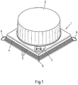
- Fig. 1 shows a preferred embodiment of a pouring element according to the invention in a perspective view obliquely from above.
- the pouring element has in the illustrated preferred embodiment a base body 1 and a screw cap 2.
- the screw cap 2 sits on one (only in the Fig. 2 and 4 recognizable) pouring tube 3.
- the main body 1 has a circumferential, truncated pyramidal flange 4.
- the shape of the flange 4 is preferably adapted to the shape and in particular to the angle of inclination of the gable region of the packing jacket to be sealed with the pouring element.
- the angled surfaces of the flange 4 have ribs 5, on the one hand reinforce the flange 4 mechanically and on the other hand should allow better connection of the gable surfaces of the packing jacket when sealing with the flange 4.
- a wing-like projection 6 is integrally formed on the flange 4. The lugs 6 also serve to improve the connection between the gable area of the packing jacket and the flange 4 of the pouring element.
- a tamper-evident seal 7 with (unspecified) formed as predetermined breaking points material bridges the body 1 with the screw 2.
- the material bridges are destroyed, so that a consumer can easily see if a provided with this pouring pack before ever has been opened.
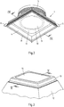
- Fig. 2 shows the pouring element according to the invention in a perspective view obliquely from below. It can be seen that in the area of the lower edge of the Inside the flange 4 a circumferential holding element 8 extends. This serves to reliably ensure a positive connection with the free end of a mandrel of a mandrel wheel during the production process of the packaging. It can also be seen that the underside of the pouring tube 3 is closed by a support wall 9, which is formed integrally with the base body 1. In the illustrated and preferred embodiment, the base body 1 also has a concentric with the Ausg screentubus 3 extending weakening zone 10, which significantly facilitates the insertion and cutting of a (not visible) cutting element inside the Ausg discerntubus 3 by appropriate material weakening.
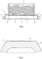
- the weakening zone 10 can be particularly well in the vertical section of the pouring in Fig. 4 detect.
- a barrier film 11 below the main body 1 in the later opening area ensures sufficient durability and aroma protection of the filled product.
- the upper part of a mandrel 12 corresponding to the pouring element described above is shown. It can be clearly seen the circumferential groove 13 as a counterpart to the circumferential projection 8 of the pouring element.
- the teaching of the invention also includes a mandrel, in which the holding element is designed as a circumferential projection, which corresponds with a pouring element with a groove as a circumferential holding element.
- a recess 14 for receiving the barrier film 11 is provided, which protects them during the sealing process from damage.
Landscapes
- Engineering & Computer Science (AREA)
- Mechanical Engineering (AREA)
- Closures For Containers (AREA)
- Packages (AREA)
- Cartons (AREA)
- Auxiliary Devices For And Details Of Packaging Control (AREA)
- Making Paper Articles (AREA)
Description
- Die Erfindung betrifft zunächst ein wiederverschließbares Ausgießelement für eine Verpackung nach dem Oberbegriff von Anspruch 1 sowie einen Dorn eines drehbaren Dornrades einer Verpackungsmaschine mit einem freien Ende zur Aufnahme eines solchen korrespondierenden Ausgießelementes. Darüber hinaus umfasst die Erfindung auch eine Kombination aus einem solchen wiederverschließbaren Ausgießelement für Verpackungen und einem während des Herstellungvorgangs der Verpackung zur formschlüssigen Verbindung mit dem Ausgießelement dienenden Dorn eines drehbaren Dornrades einer Verpackungsmaschine.
- Wenn nachfolgend kurz von wiederverschließbaren "Ausgießelementen" die Rede ist, so sind damit in der Regel kombinierte ,Öffnungs- und Ausgießelemente' gemeint, welche auf Getränkeverbundverpackungen angeordnet sind, um sie zu öffnen, um den Ausgießvorgang zu erleichtern und um sie wieder zu verschließen, um das Produkt und darin enthaltene Aromastoffe etc. vor Oxidation zu bewahren.
- Wiederverschließbare Ausgießelemente für Verpackungen, insbesondere Verbundverpackungen für flüssige Lebensmittel, sind aus der Praxis in zahlreichen Varianten bekannt. Unter Verbundverpackungen werden Verpackungen aus einem Packstoff verstanden, der aus mehreren vollflächig miteinander verbundenen Materialien, etwa Karton und Kunststoff, besteht. Bei den flüssigen Lebensmitteln kann es sich beispielsweise um Getränke, Suppen, Joghurt oder dergleichen handeln.
- Ein gattungsgemäßes wiederverschließbares Ausgießelement ist aus der auf die Anmelderin zurückgehenden
DE 10 2010 048415 A1 bekannt. Dort ist ein Ausgießelement gemäß dem Oberbegriff von Anspruch 1 beschrieben, das zum Verbinden mit einem entsprechenden Packungsmantel auf die entsprechend geformte Oberseite eines Dorns eines Dornrades einer Siegelmaschine geklemmt wird, bevor der Packungsmantel auf den Dorn aufgeschoben und beide Elemente miteinander versiegelt werden. Zum Verklemmen mit dem Dorn weist das bekannte Ausgießelement mehrere Vorsprünge auf, die in entsprechende Nuten des Dorns eingreifen. Zum Erreichen eines festen Haltes sind die Vorsprünge im Inneren des Flansches des Ausgießelementes relativ weit ausladend und auch die entsprechenden Nuten im Dorn relativ tief ausgeführt. - Dies ist nachteilig, da es durch die relativ tiefen Ausnehmungen im Dorn beim Lösen der mit dem Packungsmantel versiegelten Ausgießelemente durch Abstreifen vom Dorn zu Problemen kommen konnte. Auch eine Verringerung der Tiefe der Ausnehmungen führte nicht zu einer befriedigenden Lösung, da ein sicherer Halt des Ausgießelementes auf dem Dorn nicht immer gegeben war. Des Weiteren ist eine zuverlässige Reinigung dieser Hohlräume nur mit relativ großem Aufwand möglich. Eine perfekte Reinigung ist hier jedoch zwingend erforderlich, da die Vorsprünge im Ausgießelement im Inneren der Packung mit dem abgefüllten Produkt in Berührung kommen und dort befindlicher Schmutz, Bakterien etc. zu einer Kontamination des Packungsinhaltes führen würde.
- Die gleichfalls auf die Anmelderin zurückgehende
DE 10 2010 050 502 A1 beschreibt ein Verfahren zur Herstellung einer Verbundverpackung mit einem gattungsgemäßen Ausgießelement unter Verwendung eines Dornrades zur Versiegelung mit dem Packungsmantel. Dort ist gezeigt, wie die Ausgießelemente auf den Dorn aufgebracht werden. - Auch ist es aus der
JP 2009-039980 (A - Des Weiteren ist es aus der
WO 2010/106327 A1 bekannt, ein Ausgießelement vor dem Versiegeln mit einer Verpackung temporär an einem Dorn zu befestigen. Dazu weist der Dorn eine, etwa dem inneren Durchmesser des Ausgießelements entsprechende, umlaufende Rippe auf, welche mit einer Mehrzahl von an der Innenoberfläche des Ausgießelements umlaufend verteilt angeordneten, stegartigen Vorsprüngen zusammenwirkt, so dass ein axiales Aufschieben des Ausgießelementes auf den Dorn zu einer formschlüssigen Verrastung führt. Diese Lösung ist aufwändig, da jedes Ausgießelement mit entsprechenden Klemmelementen versehen sein muss.
Davon ausgehend liegt der Erfindung daher die Aufgabe zugrunde, das eingangs erwähnte und zuvor näher beschriebene wiederverschließbare Ausgießelement und einen entsprechenden Dorn so auszugestalten und weiterzubilden, dass eine zuverlässige Verbindung des wiederverschließbaren Ausgießelementes beim Versiegeln mit einem Packungsmantel auf einem Dorn eines Dornrades auch beim Verschwenken des Dorns bis zum eigentlichen Versiegeln und anschließend ein einfaches Entfernen vom Dorn ermöglicht wird. Darüber hinaus ist auch eine gute Reinigungsmöglichkeit des Dornes erwünscht.
Gelöst wird diese Aufgabe bei einem wiederverschließbaren Ausgießelement durch ein Ausgießelement mit allen Merkmalen von Patentanspruch 1.
Dazu korrespondierend ist ein Dorn nach Patentanspruch 7 im Aufnahmebereich des Ausgießelementes pyramidenstumpfförmig und weist ein umlaufendes Halteelement zur formschlüssigen Wirkverbindung mit dem Ausgießelement auf. - Die Kombination nach Anspruch 11 aus einem wiederverschließbaren Ausgießelement für Verpackungen und einem zugehörigen Dorn eines Dornrades löst die Aufgabe dadurch, dass zur formschlüssigen Verbindung von Ausgießelement und Dorn miteinander korrespondierende, umlaufende Halteelemente vorgesehen sind.
- Auf diese Weise wird bei der Herstellung der Verbundverpackung aus Ausgießelement und Packungsmantel das Ausgießelement ausreichend fest mit dem Dorn formschlüssig verbunden, um den Dorn in die Aufschiebestellung des Packungsmantels bewegen zu können.
Überraschender Weise hat sich gezeigt, dass auch ein umlaufendes Halteelement ein sicheres und definiertes zeitweiliges Halten und ein problemloses Abziehen vom Dorn erlaubt. Durch die deutliche Verlängerung des Kontaktbereiches zwischen Ausgießelement und Dorn reicht eine geringere Tiefe des Halteelementes aus, wodurch sich auch der Reinigungsaufwand des Dornes reduziert. - Eine weitere Lehre der Erfindung sieht vor, dass das umlaufende Halteelement im Bereich der Unterkante der Innenseite des Flansches verläuft. Dies ist sowohl für die Herstellung des Ausgießelementes in einer Spritzgießform als auch für die Bearbeitung des Dornes von Vorteil.
- Nach einer weiteren Ausgestaltung der Erfindung ist das umlaufende Halteelement des Flansches als Vorsprung ausgebildet. Alternativ ist es auch denkbar, dass das umlaufende Halteelement als Nut ausgebildet ist.
In weiterer vorteilhafter Ausführung weist der Grundkörper des Ausgießelementes eine quadratische Grundplatte auf, deren Flansch pyramidenstumpfförmig ausgebildet ist. Hierdurch lässt sich eine besonders gleichmäßige Verteilung der Kräfte zwischen Packungsmantel und Ausgießelement erreichen.
Nach einer weiteren Lehre der Erfindung ist der Grundkörper unterhalb des Ausgießtubus mittels einer Stützwand geschlossen und weist eine umlaufende Schwächungszone auf. Dadurch kann der Öffnungsvorgang mittels einem im Ausgießtubus angeordneten Öffnungselement (beispielsweise Pullring oder Schneidelement, beides für sich bekannt) mit geringen Kräften erfolgen. - Es ist im Rahmen der Erfindung jedoch auch alternativ möglich, dass der Grundkörper eine zum Ausgießtubus konzentrische Öffnung aufweist.
- In jedem Fall ist es nach einer weiteren Lehre der Erfindung von Vorteil, wenn der Grundkörper unterhalb der Stützwand bzw. der Öffnung eine Barrierefolie aufweist. Dadurch wird auch im Bereich des Ausgießelementes eine Sauerstoffbarriere der Verpackung erreicht.
- Weitere zweckmäßige Ausgestaltungen der Erfindung sehen vor, dass auch das umlaufende Halteelement des Dorns als Nut - oder alternativ als Vorsprung - ausgebildet ist.
- Ist das Ausgießelement mit einer Barrierefolie unterhalb der Stützwand des Grundkörpers versehen, so ist es zweckmäßig, dass der Dorn eine ausreichend groß dimensionierte Ausnehmung zur Aufnahme der Barrierefolie aufweist. Hierdurch wird beim Aufsiegelvorgang des Packungsmantels ein hinreichender Schutz der Barrierefolie vor einer thermischen oder mechanischen Beschädigung gewährleistet.
- Die Erfindung wird nachfolgend anhand einer lediglich ein bevorzugtes Ausführungsbeispiel darstellenden Zeichnung näher erläutert. In der Zeichnung zeigen
- Fig. 1
- ein erfindungsgemäßes wiederverschließbares Ausgießelement in perspektivischer Ansicht von oben,
- Fig. 2
- das wiederverschließbare Ausgießelement aus
Fig. 1 in perspektivischer Ansicht von unten, - Fig. 3
- den oberen Teil eines Dornes eines drehbaren Dornrades zur Aufnahme des wiederverschließbaren Ausgießelementes in perspektivischer Ansicht von oben,
- Fig. 4
- das wiederverschließbare Ausgießelement aus
Fig. 1 im Vertikalschnitt (ohne Schneidelement) und - Fig. 5
- den Dorn aus
Fig. 3 im Vertikalschnitt. -
Fig. 1 zeigt ein bevorzugtes Ausführungsbeispiel eines erfindungsgemäßen Ausgießelementes in einer perspektivischen Darstellung von schräg oben. Das Ausgießelement weist im dargestellten und insoweit bevorzugten Ausführungsbeispiel einen Grundkörper 1 und einen Schraubdeckel 2 auf. Der Schraubdeckel 2 sitzt auf einem (nur in denFig. 2 und4 erkennbaren) Ausgießtubus 3. Der Grundkörper 1 weist einen umlaufenden, pyramidenstumpfförmigen Flansch 4 auf. Die Form des Flansches 4 ist vorzugsweise an die Form und insbesondere an den Neigungswinkel des Giebelbereichs des mit dem Ausgießelement zu versiegelnden Packungsmantels angepasst. - Die abgewinkelten Flächen des Flansches 4 weisen Rippen 5 auf, die einerseits den Flansch 4 mechanisch verstärken und andererseits eine bessere Anbindung der Giebelflächen des Packungsmantels beim Versiegeln mit dem Flansch 4 ermöglichen sollen. In jedem Eckbereich ist ein flügelartiger Ansatz 6 an den Flansch 4 angeformt. Auch die Ansätze 6 dienen dazu, die Verbindung zwischen dem Giebelbereich des Packungsmantels und dem Flansch 4 des Ausgießelements zu verbessern.
- Bei dem in
Fig. 1 dargestellten Ausgießelement verbindet ein Originalitätssiegel 7 mit (nicht näher bezeichneten) als Sollbruchstellen ausgebildeten Materialbrücken den Grundkörper 1 mit dem Schraubdeckel 2. Beim erstmaligen Öffnen werden die Materialbrücken zerstört, so dass ein Verbraucher leicht erkennen kann, ob eine mit diesem Ausgießelement versehene Packung zuvor schon einmal geöffnet worden ist. -
Fig. 2 zeigt das erfindungsgemäße Ausgießelement in einer perspektivischen Darstellung von schräg unten. Man erkennt, dass im Bereich der Unterkante der Innenseite des Flansches 4 ein umlaufendes Halteelement 8 verläuft. Dieses dient dazu, beim Herstellvorgang der Verpackung eine formschlüssige Verbindung mit dem freien Ende eines Dornes eines Dornrades zuverlässig zu gewährleisten. Man erkennt ferner, dass die Unterseite des Ausgießtubus 3 von einer Stützwand 9 verschlossen ist, die einstückig mit dem Grundkörper 1 ausgebildet ist.
Im dargestellten und bevorzugten Ausführungsbeispiel verfügt der Grundkörper 1 auch über eine konzentrisch zum Ausgießtubus 3 verlaufende Schwächungszone 10, die das Einstechen und Aufschneiden eines (nicht erkennbaren) Schneidelementes im Inneren des Ausgießtubus 3 durch entsprechende Materialschwächung deutlich erleichtert. Die genaue Ausbildung der Schwächungszone 10 lässt sich besonders gut im Vertikalschnitt des Ausgießelementes inFig. 4 erkennen.
Eine Barrierefolie 11 unterhalb des Grundkörpers 1 im späteren Öffnungsbereich sorgt für eine ausreichende Haltbarkeit sowie einen Aromaschutz des abgefüllten Produkts.
In denFig. 3 und5 ist der obere Teil eines mit dem zuvor beschriebenen Ausgießelement korrespondierenden Dorns 12 dargestellt. Man erkennt deutlich die umlaufende Nut 13 als Pendant zum umlaufenden Vorsprung 8 des Ausgießelementes. Wie ausgeführt, wenn auch nicht dargestellt, umfasst die Lehre der Erfindung auch einen Dorn, bei dem das Halteelement als umlaufender Vorsprung ausgebildet ist, der mit einem Ausgießelement mit einer Nut als umlaufendes Halteelement korrespondiert. Schließlich geht aus denFig. 3 und5 auch hervor, dass auf der abgeflachten Oberseite des Dornes 12 eine Ausnehmung 14 zur Aufnahme der Barrierefolie 11 vorgesehen ist, die diese beim Siegelvorgang vor einer Beschädigung schützt.
Claims (11)
- Wiederverschließbares Ausgießelement für eine Verpackung, insbesondere eine Verbundverpackung für flüssige Lebensmittel, mit einem Grundkörper (1), welcher einen durch einen Schraubdeckel (2) verschlossenen Ausgießtubus (3) und einen Flansch (4) mit polyederförmigen Flächen zur Verbindung mit einem Packungsmantel aufweist, wobei der Grundkörper (1) eine quadratische Grundplatte aufweist und wobei der Flansch (4) des Grundkörpers (1) pyramidenstumpfförmig ausgebildet ist, und wobei das Ausgießelement im Inneren des Grundkörpers (1) ein Halteelement (8) zur formschlüssigen Wirkverbindung mit einem Dorn (12) einer Verpackungsmaschine aufweist, das im Bereich der Unterkante der Innenseite des Flansches (4) angeordnet ist,
dadurch gekennzeichnet, dass
das Halteelement (8) umlaufend verläuft. - Wiederverschließbares Ausgießelement nach Anspruch 1,
dadurch gekennzeichnet, dass
das umlaufende Halteelement (8) des Flansches (4) als Vorsprung ausgebildet ist. - Wiederverschließbares Ausgießelement nach Anspruch 1,
dadurch gekennzeichnet, dass
das umlaufende Halteelement als Nut ausgebildet ist. - Wiederverschließbares Ausgießelement nach einem der Ansprüche 1 bis 3,
dadurch gekennzeichnet, dass
der Grundkörper (1) unterhalb des Ausgießtubus (3) mittels einer Stützwand (9) geschlossen ist und eine umlaufende Schwächungszone (10) aufweist. - Wiederverschließbares Ausgießelement nach einem der Ansprüche 1 bis 3,
dadurch gekennzeichnet, dass
der Grundkörper eine zum Ausgießtubus konzentrische Öffnung aufweist. - Wiederverschließbares Ausgießelement nach einem der Ansprüche 4 oder 5
dadurch gekennzeichnet, dass
der Flansch (4) unterhalb der Stützwand (9), bzw. der Öffnung, eine Barrierefolie aufweist. - Dorn (12) eines drehbaren Dornrades einer Verpackungsmaschine mit einem freien Ende zur Aufnahme eines korrespondierenden wiederverschließbaren Ausgießelementes nach einem der Ansprüche 1 bis 6,
wobei der Dorn (12) im Aufnahmebereich des Ausgießelementes pyramidenstumpfförmig ist und ein umlaufendes Halteelement (13) zur formschlüssigen Wirkverbindung mit dem Ausgießelement aufweist. - Dorn nach Anspruch 7,
dadurch gekennzeichnet, dass
das umlaufende Halteelement (13) als Nut ausgebildet ist. - Dorn nach Anspruch 7,
dadurch gekennzeichnet, dass
das umlaufende Halteelement als Vorsprung ausgebildet ist. - Dorn nach einem der Ansprüche 7 bis 9,
dadurch gekennzeichnet, dass
auf der Oberseite des Dornes (12) eine Ausnehmung (14) zur Aufnahme der Barrierefolie (11) aufweist. - Kombination aus einem wiederverschließbaren Ausgießelement für Verpackungen nach einem der Ansprüche 1 bis 6, und einem, während des Herstellungvorgangs der Verpackung, zur formschlüssigen Verbindung mit dem Ausgießelement dienenden, Dorn eines drehbaren Dornrades einer Verpackungsmaschine nach einem der Ansprüche 7 bis 10,
wobei zur formschlüssigen Verbindung von Ausgießelement und Dorn miteinander korrespondierende, umlaufende Halteelemente vorgesehen sind.
Priority Applications (1)
| Application Number | Priority Date | Filing Date | Title |
|---|---|---|---|
| PL13752878T PL2909092T3 (pl) | 2012-10-19 | 2013-08-12 | Wielokrotnie zamykany element wylewowy do opakowania i trzpień obrotowego koła trzpieniowego maszyny pakującej do umieszczenia takiego elementu wylewowego oraz kombinacja elementu wylewowego i trzpienia |
Applications Claiming Priority (2)
| Application Number | Priority Date | Filing Date | Title |
|---|---|---|---|
| DE102012020529.5A DE102012020529A1 (de) | 2012-10-19 | 2012-10-19 | Wiederverschließbares Ausgießelement für eine Verpackung und Dorn eines drehbaren Dornrades einer Verpackungsmaschine zur Aufnahme eines solchen Ausgießelementes und Kombination von Ausgießelement und Dorn |
| PCT/EP2013/066808 WO2014060133A1 (de) | 2012-10-19 | 2013-08-12 | WIEDERVERSCHLIEßBARES AUSGIEßELEMENT FÜR EINE VERPACKUNG UND DORN EINES DREHBAREN DORNRADES EINER VERPACKUNGSMASCHINE ZUR AUFNAHME EINES SOLCHEN AUSGIEßELEMENTES UND KOMBINATION VON AUSGIEßELEMENT UND DORN |
Publications (2)
| Publication Number | Publication Date |
|---|---|
| EP2909092A1 EP2909092A1 (de) | 2015-08-26 |
| EP2909092B1 true EP2909092B1 (de) | 2018-10-31 |
Family
ID=49034077
Family Applications (1)
| Application Number | Title | Priority Date | Filing Date |
|---|---|---|---|
| EP13752878.2A Active EP2909092B1 (de) | 2012-10-19 | 2013-08-12 | Wiederverschliessbares ausgiesselement für eine verpackung und dorn eines drehbaren dornrades einer verpackungsmaschine zur aufnahme eines solchen ausgiesselementes und kombination von ausgiesselement und dorn |
Country Status (12)
| Country | Link |
|---|---|
| US (1) | US20150259109A1 (de) |
| EP (1) | EP2909092B1 (de) |
| CN (1) | CN104781151B (de) |
| AU (1) | AU2013331990B2 (de) |
| BR (1) | BR112015007874B1 (de) |
| DE (1) | DE102012020529A1 (de) |
| ES (1) | ES2699402T3 (de) |
| MX (1) | MX362443B (de) |
| PL (1) | PL2909092T3 (de) |
| RU (1) | RU2642355C2 (de) |
| WO (1) | WO2014060133A1 (de) |
| ZA (1) | ZA201502124B (de) |
Families Citing this family (13)
| Publication number | Priority date | Publication date | Assignee | Title |
|---|---|---|---|---|
| GB201205243D0 (en) | 2012-03-26 | 2012-05-09 | Kraft Foods R & D Inc | Packaging and method of opening |
| GB2511559B (en) | 2013-03-07 | 2018-11-14 | Mondelez Uk R&D Ltd | Improved Packaging and Method of Forming Packaging |
| GB2511560B (en) | 2013-03-07 | 2018-11-14 | Mondelez Uk R&D Ltd | Improved Packaging and Method of Forming Packaging |
| DE102015110526B4 (de) * | 2015-06-30 | 2018-08-23 | Sig Technology Ag | Ausgiesselement für eine Verpackung sowie Verbundverpackung mit einem solchen Ausgiesselement |
| EP3112283B1 (de) | 2015-06-30 | 2018-01-31 | SIG Technology AG | Ausgiesselement für eine verpackung sowie verbundverpackung mit einem solchen ausgiesselement |
| WO2017001162A1 (de) * | 2015-06-30 | 2017-01-05 | Sig Technology Ag | Ausgiesselement für eine verpackung sowie verbundverpackung mit einem solchen ausgiesselement |
| ES2660266T3 (es) * | 2015-06-30 | 2018-03-21 | Sig Technology Ag | Elemento de vertido para un envase, así como envase compuesto con un elemento de vertido de este tipo |
| CN107810148B (zh) * | 2015-06-30 | 2019-04-09 | Sig技术股份公司 | 用于包装件的倾倒元件以及具有这种倾倒元件的复合包装件 |
| DE102015110529B4 (de) * | 2015-06-30 | 2018-07-26 | Sig Technology Ag | Ausgiesselement für eine Verpackung sowie Verbundverpackung mit einem solchen Ausgiesselement |
| WO2021046413A1 (en) | 2019-09-06 | 2021-03-11 | Silgan White Cap LLC | Tethered, hinged closure |
| EP4429966A4 (de) | 2021-11-08 | 2026-01-14 | Silgan White Cap LLC | Vorsprung an einem behälterhals |
| CA3247359A1 (en) | 2022-02-11 | 2023-08-17 | Silgan White Cap LLC | ATTACHED HINGE CLOSURE WITH MODIFIED PRIMARY SLOT |
| US20240409272A1 (en) * | 2023-06-12 | 2024-12-12 | Trl Automotive, Llc | Liquid transport hi-flow spout & system |
Family Cites Families (34)
| Publication number | Priority date | Publication date | Assignee | Title |
|---|---|---|---|---|
| US3443713A (en) * | 1966-12-21 | 1969-05-13 | John Kosar | Cornered blanks for closure caps,liners,washers,etc.,plus method of blanking and forming the blanks and utilizing the corners thereof |
| US3690524A (en) * | 1969-04-26 | 1972-09-12 | Thimonnier & Cie | Mouthpiece for a plastics material bag, packet, receptacle sachet or the like |
| US3824145A (en) * | 1969-06-20 | 1974-07-16 | Continental Plastic Ag | Apparatus for bonding a thermoplastic tubular part to the periphery of a thermoplastic tube head |
| US4516718A (en) * | 1983-09-20 | 1985-05-14 | Westvaco Corporation | Carton with automatic lock |
| FR2647088B1 (fr) * | 1989-05-17 | 1991-11-22 | Rical Sa | Ensemble verseur et capsule de bouchage avec charniere a ressort |
| US5219507A (en) * | 1989-07-27 | 1993-06-15 | Owens-Illinois Closure Inc. | Method of making a tamper indicating package |
| JPH0390833U (de) * | 1989-12-28 | 1991-09-17 | ||
| CH683611A5 (de) * | 1991-09-10 | 1994-04-15 | Zeller Plastik Koehn Graebner | Verfahren und Werkzeug zur Herstellung eines Verschlusses für Behälter sowie nach dem Verfahren hergestellter Verschluss. |
| FR2721282B1 (fr) * | 1994-06-21 | 1996-12-27 | Moulage Automatique Sa | Perfectionnement à un procédé de fabrication d'un dispositif de bouchage et machine pour sa mise en Óoeuvre. |
| US6464096B2 (en) * | 1995-01-30 | 2002-10-15 | Portola Packaging, Inc. | Fitment having removable membrane |
| JPH10513137A (ja) * | 1995-01-30 | 1998-12-15 | ポートラ パッケイジング インコーポレイテッド | 除去可能膜を備えた口具 |
| US5957312A (en) * | 1995-01-30 | 1999-09-28 | Portola Packaging, Inc. | Fitment having removable membrane |
| US5759143A (en) * | 1996-11-01 | 1998-06-02 | Portola Packaging, Inc. | Fitment applicator |
| US5735426A (en) * | 1996-12-17 | 1998-04-07 | Alcoa Closure Systems International Inc. | Fitment-closure assembly for gable-topped carton |
| IT1293269B1 (it) * | 1997-07-25 | 1999-02-16 | Sacmi | Capsula a vite in materiale plastico con anello di garanzia. |
| US5855544A (en) * | 1997-08-12 | 1999-01-05 | Technical Developers, Inc. | Flexible container with tubular fitment and method and apparatus for assembling same |
| JP4588149B2 (ja) * | 2000-02-01 | 2010-11-24 | 大成化工株式会社 | キャップ型結合封止具と容器との組合せ体 |
| DE10133809A1 (de) * | 2001-07-11 | 2003-01-23 | Bericap Gmbh & Co Kg | Verschlussunterteil mit Haltesteg |
| US6860406B2 (en) * | 2001-08-13 | 2005-03-01 | Illinois Tool Works Inc. | Flexible pouch fitment structure |
| US6702161B2 (en) * | 2001-12-12 | 2004-03-09 | Portola Packaging, Inc. | Closure having rotatable spout and axially movable stem |
| US20030116579A1 (en) * | 2001-12-20 | 2003-06-26 | Chambers James D. | Plastic chime ring and apparatus |
| US6926162B1 (en) * | 2002-02-05 | 2005-08-09 | Rexam Medical Packaging Inc. | Tamper indicating band arrester |
| ITBO20020133A1 (it) * | 2002-03-20 | 2003-09-22 | Azionaria Costruzioni Acma Spa | Condotto di comunicazione per contenitori e contenitore munito di tale condotto |
| CA2495191C (en) * | 2002-07-12 | 2012-06-05 | Bericap | Closure comprising a hinged cap moulded in closed position |
| SE526058C8 (sv) * | 2002-12-13 | 2005-07-27 | Tetra Laval Holdings & Finance | Förfarande och anordning för att tillverka förpackningar |
| GB0230237D0 (en) * | 2002-12-28 | 2003-02-05 | Elopak Systems | Apparatus and method |
| US8104250B2 (en) * | 2004-11-16 | 2012-01-31 | Elopak Systems Ag | Apparatus for use in and method of attachiing cap-form fitments to containers |
| CH698661B1 (de) * | 2006-01-29 | 2009-09-30 | Belcap Switzerland Ag | Verschliessvorrichtung mit partiell kreisrundem Schneidering. |
| DE102006016113B3 (de) * | 2006-04-04 | 2007-08-23 | Sig Technology Ag | Wiederverschließbares Ausgießelement für Karton/Kunststoff-Verbundpackungen |
| JP2009039980A (ja) | 2007-08-10 | 2009-02-26 | Nippon Paper-Pak Co Ltd | 注出口装着装置 |
| GB0904495D0 (en) | 2009-03-17 | 2009-04-29 | Elopak Systems | Improvements in or relating to pour spouts |
| DE102010048415A1 (de) * | 2010-10-15 | 2012-04-19 | Sig Technology Ag | Wiederverschließbares Ausgießelement mit Barrierefolie und Stützwand |
| DE102010050502A1 (de) * | 2010-11-08 | 2012-05-10 | Sig Technology Ag | Vorrichtung und Verfahren zur Herstellung einer Verpackung |
| JP5291175B2 (ja) * | 2011-12-16 | 2013-09-18 | 日本クロージャー株式会社 | 合成樹脂製容器蓋及びこれと容器との組み合わせ |
-
2012
- 2012-10-19 DE DE102012020529.5A patent/DE102012020529A1/de not_active Ceased
-
2013
- 2013-08-12 US US14/434,305 patent/US20150259109A1/en not_active Abandoned
- 2013-08-12 BR BR112015007874-5A patent/BR112015007874B1/pt active IP Right Grant
- 2013-08-12 RU RU2015118574A patent/RU2642355C2/ru not_active IP Right Cessation
- 2013-08-12 EP EP13752878.2A patent/EP2909092B1/de active Active
- 2013-08-12 CN CN201380053680.7A patent/CN104781151B/zh active Active
- 2013-08-12 WO PCT/EP2013/066808 patent/WO2014060133A1/de not_active Ceased
- 2013-08-12 PL PL13752878T patent/PL2909092T3/pl unknown
- 2013-08-12 MX MX2015004523A patent/MX362443B/es active IP Right Grant
- 2013-08-12 AU AU2013331990A patent/AU2013331990B2/en not_active Ceased
- 2013-08-12 ES ES13752878T patent/ES2699402T3/es active Active
-
2015
- 2015-03-27 ZA ZA2015/02124A patent/ZA201502124B/en unknown
Non-Patent Citations (1)
| Title |
|---|
| None * |
Also Published As
| Publication number | Publication date |
|---|---|
| RU2642355C2 (ru) | 2018-01-24 |
| RU2015118574A (ru) | 2016-12-10 |
| ZA201502124B (en) | 2016-01-27 |
| BR112015007874A2 (pt) | 2017-07-04 |
| US20150259109A1 (en) | 2015-09-17 |
| MX2015004523A (es) | 2015-07-14 |
| EP2909092A1 (de) | 2015-08-26 |
| ES2699402T3 (es) | 2019-02-11 |
| BR112015007874B1 (pt) | 2020-12-22 |
| AU2013331990A1 (en) | 2015-05-07 |
| AU2013331990B2 (en) | 2017-09-07 |
| MX362443B (es) | 2019-01-18 |
| CN104781151A (zh) | 2015-07-15 |
| DE102012020529A1 (de) | 2014-04-24 |
| PL2909092T3 (pl) | 2019-02-28 |
| CN104781151B (zh) | 2018-07-17 |
| WO2014060133A1 (de) | 2014-04-24 |
Similar Documents
| Publication | Publication Date | Title |
|---|---|---|
| EP2909092B1 (de) | Wiederverschliessbares ausgiesselement für eine verpackung und dorn eines drehbaren dornrades einer verpackungsmaschine zur aufnahme eines solchen ausgiesselementes und kombination von ausgiesselement und dorn | |
| EP1976764B1 (de) | Verschliessbare öffnungsvorrichtung gefertigt mit einem halbfabrikat und verfahren zur montage desselben | |
| EP1747151A1 (de) | Manipulationssicherer deckel | |
| EP3385184A1 (de) | Behältnis zum hermetisch dichten aufbewahren von produkten, insbesondere von lebensmitteln | |
| EP2382139A1 (de) | Schraubverschluss mit sicherheitsring und sicherheitssiegel, sowie verfahren zur bereitstellung eines behälters mit diesem schraubverschluss | |
| EP0675051A2 (de) | Schraubkappe mit Anschweissring | |
| EP2834162B1 (de) | Dichtscheibe zur induktionsversiegelung eines behälters | |
| EP1058654B1 (de) | Kunststoffdeckel mit kunststoffverschluss | |
| EP3710373A1 (de) | Kunststoffverschlussteil mit abtrennbarer membran | |
| EP2070826B1 (de) | Behälter mit leicht zu öffnendem Verschlusselement | |
| DE60306197T2 (de) | Gewindeverpackung mit"klick"-funktion | |
| WO2017186513A1 (de) | Schraubverschluss für grossbehälter | |
| EP1519879A1 (de) | Deckel für getränkekartonverbundpackungen sowie werkzeuge und verfahren zur herstellung eines solchen deckels sowie damit versehene getränkekartonverbundpackungen | |
| DE202010004680U1 (de) | Allseitig geschlossene Verschlusskappe mit Ausgießer | |
| EP3097022A1 (de) | Behaelterdeckel, kunststoffgefaess sowie behaelter mit einem kunststoffgefaess und einem behaelterdeckel, und verfahren zu deren herstellung | |
| EP3112283B1 (de) | Ausgiesselement für eine verpackung sowie verbundverpackung mit einem solchen ausgiesselement | |
| DE19629148C2 (de) | Verfahren zur Herstellung eines befüllten Behälters | |
| EP0921985B1 (de) | Verfahren zur herstellung eines befüllten behälters | |
| EP3160894B1 (de) | Vorrichtung und verfahren zum aufbringen einer verschlusskapsel auf ein im wesentlichen zylindrisches gefäss | |
| EP3098175A1 (de) | Behältnis mit mündungsnut | |
| EP3052394B1 (de) | Behälterverschluss sowie behälter mit einem solchen behälterverschluss | |
| DE102005055036A1 (de) | Verschluß mit Membransiegel und Zusatzdichtung | |
| WO2013182344A1 (de) | Kombinationsverpackung und verfahren zum herstellen einer kombinationsverpackung | |
| DE4207841A1 (de) | Stopfen fuer einen behaelter und verfahren zur herstellung des stopfens | |
| AT500066A1 (de) | Verpackungsbehälter mit deckel |
Legal Events
| Date | Code | Title | Description |
|---|---|---|---|
| PUAI | Public reference made under article 153(3) epc to a published international application that has entered the european phase |
Free format text: ORIGINAL CODE: 0009012 |
|
| 17P | Request for examination filed |
Effective date: 20150225 |
|
| AK | Designated contracting states |
Kind code of ref document: A1 Designated state(s): AL AT BE BG CH CY CZ DE DK EE ES FI FR GB GR HR HU IE IS IT LI LT LU LV MC MK MT NL NO PL PT RO RS SE SI SK SM TR |
|
| AX | Request for extension of the european patent |
Extension state: BA ME |
|
| DAX | Request for extension of the european patent (deleted) | ||
| 17Q | First examination report despatched |
Effective date: 20160506 |
|
| STAA | Information on the status of an ep patent application or granted ep patent |
Free format text: STATUS: EXAMINATION IS IN PROGRESS |
|
| GRAP | Despatch of communication of intention to grant a patent |
Free format text: ORIGINAL CODE: EPIDOSNIGR1 |
|
| STAA | Information on the status of an ep patent application or granted ep patent |
Free format text: STATUS: GRANT OF PATENT IS INTENDED |
|
| RIC1 | Information provided on ipc code assigned before grant |
Ipc: B31B 50/84 20170101ALI20180628BHEP Ipc: B65D 5/74 20060101AFI20180628BHEP |
|
| INTG | Intention to grant announced |
Effective date: 20180725 |
|
| GRAS | Grant fee paid |
Free format text: ORIGINAL CODE: EPIDOSNIGR3 |
|
| GRAA | (expected) grant |
Free format text: ORIGINAL CODE: 0009210 |
|
| STAA | Information on the status of an ep patent application or granted ep patent |
Free format text: STATUS: THE PATENT HAS BEEN GRANTED |
|
| AK | Designated contracting states |
Kind code of ref document: B1 Designated state(s): AL AT BE BG CH CY CZ DE DK EE ES FI FR GB GR HR HU IE IS IT LI LT LU LV MC MK MT NL NO PL PT RO RS SE SI SK SM TR |
|
| REG | Reference to a national code |
Ref country code: CH Ref legal event code: EP Ref country code: GB Ref legal event code: FG4D Free format text: NOT ENGLISH |
|
| REG | Reference to a national code |
Ref country code: CH Ref legal event code: NV Representative=s name: SCHMAUDER AND PARTNER AG PATENT- UND MARKENANW, CH Ref country code: AT Ref legal event code: REF Ref document number: 1059090 Country of ref document: AT Kind code of ref document: T Effective date: 20181115 |
|
| REG | Reference to a national code |
Ref country code: DE Ref legal event code: R096 Ref document number: 502013011491 Country of ref document: DE |
|
| REG | Reference to a national code |
Ref country code: IE Ref legal event code: FG4D Free format text: LANGUAGE OF EP DOCUMENT: GERMAN |
|
| REG | Reference to a national code |
Ref country code: ES Ref legal event code: FG2A Ref document number: 2699402 Country of ref document: ES Kind code of ref document: T3 Effective date: 20190211 |
|
| REG | Reference to a national code |
Ref country code: NL Ref legal event code: MP Effective date: 20181031 |
|
| REG | Reference to a national code |
Ref country code: LT Ref legal event code: MG4D |
|
| PG25 | Lapsed in a contracting state [announced via postgrant information from national office to epo] |
Ref country code: FI Free format text: LAPSE BECAUSE OF FAILURE TO SUBMIT A TRANSLATION OF THE DESCRIPTION OR TO PAY THE FEE WITHIN THE PRESCRIBED TIME-LIMIT Effective date: 20181031 Ref country code: LV Free format text: LAPSE BECAUSE OF FAILURE TO SUBMIT A TRANSLATION OF THE DESCRIPTION OR TO PAY THE FEE WITHIN THE PRESCRIBED TIME-LIMIT Effective date: 20181031 Ref country code: HR Free format text: LAPSE BECAUSE OF FAILURE TO SUBMIT A TRANSLATION OF THE DESCRIPTION OR TO PAY THE FEE WITHIN THE PRESCRIBED TIME-LIMIT Effective date: 20181031 Ref country code: LT Free format text: LAPSE BECAUSE OF FAILURE TO SUBMIT A TRANSLATION OF THE DESCRIPTION OR TO PAY THE FEE WITHIN THE PRESCRIBED TIME-LIMIT Effective date: 20181031 Ref country code: BG Free format text: LAPSE BECAUSE OF FAILURE TO SUBMIT A TRANSLATION OF THE DESCRIPTION OR TO PAY THE FEE WITHIN THE PRESCRIBED TIME-LIMIT Effective date: 20190131 Ref country code: IS Free format text: LAPSE BECAUSE OF FAILURE TO SUBMIT A TRANSLATION OF THE DESCRIPTION OR TO PAY THE FEE WITHIN THE PRESCRIBED TIME-LIMIT Effective date: 20190228 Ref country code: NO Free format text: LAPSE BECAUSE OF FAILURE TO SUBMIT A TRANSLATION OF THE DESCRIPTION OR TO PAY THE FEE WITHIN THE PRESCRIBED TIME-LIMIT Effective date: 20190131 |
|
| PG25 | Lapsed in a contracting state [announced via postgrant information from national office to epo] |
Ref country code: PT Free format text: LAPSE BECAUSE OF FAILURE TO SUBMIT A TRANSLATION OF THE DESCRIPTION OR TO PAY THE FEE WITHIN THE PRESCRIBED TIME-LIMIT Effective date: 20190301 Ref country code: NL Free format text: LAPSE BECAUSE OF FAILURE TO SUBMIT A TRANSLATION OF THE DESCRIPTION OR TO PAY THE FEE WITHIN THE PRESCRIBED TIME-LIMIT Effective date: 20181031 Ref country code: RS Free format text: LAPSE BECAUSE OF FAILURE TO SUBMIT A TRANSLATION OF THE DESCRIPTION OR TO PAY THE FEE WITHIN THE PRESCRIBED TIME-LIMIT Effective date: 20181031 Ref country code: SE Free format text: LAPSE BECAUSE OF FAILURE TO SUBMIT A TRANSLATION OF THE DESCRIPTION OR TO PAY THE FEE WITHIN THE PRESCRIBED TIME-LIMIT Effective date: 20181031 Ref country code: AL Free format text: LAPSE BECAUSE OF FAILURE TO SUBMIT A TRANSLATION OF THE DESCRIPTION OR TO PAY THE FEE WITHIN THE PRESCRIBED TIME-LIMIT Effective date: 20181031 Ref country code: GR Free format text: LAPSE BECAUSE OF FAILURE TO SUBMIT A TRANSLATION OF THE DESCRIPTION OR TO PAY THE FEE WITHIN THE PRESCRIBED TIME-LIMIT Effective date: 20190201 |
|
| PG25 | Lapsed in a contracting state [announced via postgrant information from national office to epo] |
Ref country code: CZ Free format text: LAPSE BECAUSE OF FAILURE TO SUBMIT A TRANSLATION OF THE DESCRIPTION OR TO PAY THE FEE WITHIN THE PRESCRIBED TIME-LIMIT Effective date: 20181031 Ref country code: DK Free format text: LAPSE BECAUSE OF FAILURE TO SUBMIT A TRANSLATION OF THE DESCRIPTION OR TO PAY THE FEE WITHIN THE PRESCRIBED TIME-LIMIT Effective date: 20181031 |
|
| REG | Reference to a national code |
Ref country code: DE Ref legal event code: R097 Ref document number: 502013011491 Country of ref document: DE |
|
| PG25 | Lapsed in a contracting state [announced via postgrant information from national office to epo] |
Ref country code: SM Free format text: LAPSE BECAUSE OF FAILURE TO SUBMIT A TRANSLATION OF THE DESCRIPTION OR TO PAY THE FEE WITHIN THE PRESCRIBED TIME-LIMIT Effective date: 20181031 Ref country code: EE Free format text: LAPSE BECAUSE OF FAILURE TO SUBMIT A TRANSLATION OF THE DESCRIPTION OR TO PAY THE FEE WITHIN THE PRESCRIBED TIME-LIMIT Effective date: 20181031 Ref country code: SK Free format text: LAPSE BECAUSE OF FAILURE TO SUBMIT A TRANSLATION OF THE DESCRIPTION OR TO PAY THE FEE WITHIN THE PRESCRIBED TIME-LIMIT Effective date: 20181031 Ref country code: RO Free format text: LAPSE BECAUSE OF FAILURE TO SUBMIT A TRANSLATION OF THE DESCRIPTION OR TO PAY THE FEE WITHIN THE PRESCRIBED TIME-LIMIT Effective date: 20181031 |
|
| PLBE | No opposition filed within time limit |
Free format text: ORIGINAL CODE: 0009261 |
|
| STAA | Information on the status of an ep patent application or granted ep patent |
Free format text: STATUS: NO OPPOSITION FILED WITHIN TIME LIMIT |
|
| 26N | No opposition filed |
Effective date: 20190801 |
|
| PG25 | Lapsed in a contracting state [announced via postgrant information from national office to epo] |
Ref country code: SI Free format text: LAPSE BECAUSE OF FAILURE TO SUBMIT A TRANSLATION OF THE DESCRIPTION OR TO PAY THE FEE WITHIN THE PRESCRIBED TIME-LIMIT Effective date: 20181031 |
|
| PG25 | Lapsed in a contracting state [announced via postgrant information from national office to epo] |
Ref country code: LU Free format text: LAPSE BECAUSE OF NON-PAYMENT OF DUE FEES Effective date: 20190812 Ref country code: MC Free format text: LAPSE BECAUSE OF FAILURE TO SUBMIT A TRANSLATION OF THE DESCRIPTION OR TO PAY THE FEE WITHIN THE PRESCRIBED TIME-LIMIT Effective date: 20181031 |
|
| REG | Reference to a national code |
Ref country code: BE Ref legal event code: MM Effective date: 20190831 |
|
| PG25 | Lapsed in a contracting state [announced via postgrant information from national office to epo] |
Ref country code: IE Free format text: LAPSE BECAUSE OF NON-PAYMENT OF DUE FEES Effective date: 20190812 |
|
| PG25 | Lapsed in a contracting state [announced via postgrant information from national office to epo] |
Ref country code: BE Free format text: LAPSE BECAUSE OF NON-PAYMENT OF DUE FEES Effective date: 20190831 |
|
| REG | Reference to a national code |
Ref country code: AT Ref legal event code: MM01 Ref document number: 1059090 Country of ref document: AT Kind code of ref document: T Effective date: 20190812 |
|
| PG25 | Lapsed in a contracting state [announced via postgrant information from national office to epo] |
Ref country code: AT Free format text: LAPSE BECAUSE OF NON-PAYMENT OF DUE FEES Effective date: 20190812 |
|
| PG25 | Lapsed in a contracting state [announced via postgrant information from national office to epo] |
Ref country code: CY Free format text: LAPSE BECAUSE OF FAILURE TO SUBMIT A TRANSLATION OF THE DESCRIPTION OR TO PAY THE FEE WITHIN THE PRESCRIBED TIME-LIMIT Effective date: 20181031 |
|
| PG25 | Lapsed in a contracting state [announced via postgrant information from national office to epo] |
Ref country code: MT Free format text: LAPSE BECAUSE OF FAILURE TO SUBMIT A TRANSLATION OF THE DESCRIPTION OR TO PAY THE FEE WITHIN THE PRESCRIBED TIME-LIMIT Effective date: 20181031 Ref country code: HU Free format text: LAPSE BECAUSE OF FAILURE TO SUBMIT A TRANSLATION OF THE DESCRIPTION OR TO PAY THE FEE WITHIN THE PRESCRIBED TIME-LIMIT; INVALID AB INITIO Effective date: 20130812 |
|
| PG25 | Lapsed in a contracting state [announced via postgrant information from national office to epo] |
Ref country code: MK Free format text: LAPSE BECAUSE OF FAILURE TO SUBMIT A TRANSLATION OF THE DESCRIPTION OR TO PAY THE FEE WITHIN THE PRESCRIBED TIME-LIMIT Effective date: 20181031 |
|
| REG | Reference to a national code |
Ref country code: GB Ref legal event code: 732E Free format text: REGISTERED BETWEEN 20230713 AND 20230719 |
|
| REG | Reference to a national code |
Ref country code: ES Ref legal event code: PC2A Owner name: SIG COMBIBLOC SERVICES AG Effective date: 20231130 |
|
| REG | Reference to a national code |
Ref country code: ES Ref legal event code: PC2A Owner name: SIG SERVICES AG Effective date: 20240906 |
|
| REG | Reference to a national code |
Ref country code: DE Ref legal event code: R081 Ref document number: 502013011491 Country of ref document: DE Owner name: SIG SERVICES AG, CH Free format text: FORMER OWNER: SIG TECHNOLOGY AG, NEUHAUSEN AM RHEINFALL, CH |
|
| PGFP | Annual fee paid to national office [announced via postgrant information from national office to epo] |
Ref country code: ES Payment date: 20250917 Year of fee payment: 13 |
|
| PGFP | Annual fee paid to national office [announced via postgrant information from national office to epo] |
Ref country code: DE Payment date: 20250819 Year of fee payment: 13 |
|
| PGFP | Annual fee paid to national office [announced via postgrant information from national office to epo] |
Ref country code: PL Payment date: 20250801 Year of fee payment: 13 Ref country code: TR Payment date: 20250806 Year of fee payment: 13 Ref country code: IT Payment date: 20250829 Year of fee payment: 13 |
|
| PGFP | Annual fee paid to national office [announced via postgrant information from national office to epo] |
Ref country code: GB Payment date: 20250822 Year of fee payment: 13 |
|
| PGFP | Annual fee paid to national office [announced via postgrant information from national office to epo] |
Ref country code: FR Payment date: 20250821 Year of fee payment: 13 |
|
| PGFP | Annual fee paid to national office [announced via postgrant information from national office to epo] |
Ref country code: CH Payment date: 20250901 Year of fee payment: 13 |