EP2887887B1 - Implantat - Google Patents
Implantat Download PDFInfo
- Publication number
- EP2887887B1 EP2887887B1 EP13766232.6A EP13766232A EP2887887B1 EP 2887887 B1 EP2887887 B1 EP 2887887B1 EP 13766232 A EP13766232 A EP 13766232A EP 2887887 B1 EP2887887 B1 EP 2887887B1
- Authority
- EP
- European Patent Office
- Prior art keywords
- implant
- loops
- aneurysm
- section
- membrane
- Prior art date
- Legal status (The legal status is an assumption and is not a legal conclusion. Google has not performed a legal analysis and makes no representation as to the accuracy of the status listed.)
- Active
Links
- 239000007943 implant Substances 0.000 title claims description 211
- 206010002329 Aneurysm Diseases 0.000 claims description 119
- 239000012528 membrane Substances 0.000 claims description 99
- 230000008878 coupling Effects 0.000 claims description 30
- 238000010168 coupling process Methods 0.000 claims description 30
- 238000005859 coupling reaction Methods 0.000 claims description 30
- 210000001331 nose Anatomy 0.000 claims description 4
- 210000004379 membrane Anatomy 0.000 description 96
- 238000000926 separation method Methods 0.000 description 85
- 241000264877 Hippospongia communis Species 0.000 description 18
- 230000002792 vascular Effects 0.000 description 18
- 239000003550 marker Substances 0.000 description 16
- 239000008280 blood Substances 0.000 description 13
- 210000004369 blood Anatomy 0.000 description 13
- 230000017531 blood circulation Effects 0.000 description 13
- 238000002513 implantation Methods 0.000 description 11
- 239000000463 material Substances 0.000 description 10
- 210000004204 blood vessel Anatomy 0.000 description 9
- 239000000835 fiber Substances 0.000 description 8
- 229910001000 nickel titanium Inorganic materials 0.000 description 8
- 239000004677 Nylon Substances 0.000 description 7
- 238000003780 insertion Methods 0.000 description 7
- 230000037431 insertion Effects 0.000 description 7
- 229920001778 nylon Polymers 0.000 description 7
- HLXZNVUGXRDIFK-UHFFFAOYSA-N nickel titanium Chemical compound [Ti].[Ti].[Ti].[Ti].[Ti].[Ti].[Ti].[Ti].[Ti].[Ti].[Ti].[Ni].[Ni].[Ni].[Ni].[Ni].[Ni].[Ni].[Ni].[Ni].[Ni].[Ni].[Ni].[Ni].[Ni] HLXZNVUGXRDIFK-UHFFFAOYSA-N 0.000 description 6
- BASFCYQUMIYNBI-UHFFFAOYSA-N platinum Chemical compound [Pt] BASFCYQUMIYNBI-UHFFFAOYSA-N 0.000 description 6
- 229920000642 polymer Polymers 0.000 description 6
- 229920000914 Metallic fiber Polymers 0.000 description 5
- 239000004952 Polyamide Substances 0.000 description 5
- 238000001523 electrospinning Methods 0.000 description 5
- 238000000034 method Methods 0.000 description 5
- 229920002647 polyamide Polymers 0.000 description 5
- 230000007704 transition Effects 0.000 description 5
- 230000006978 adaptation Effects 0.000 description 4
- 230000008901 benefit Effects 0.000 description 4
- 239000003795 chemical substances by application Substances 0.000 description 4
- 230000001788 irregular Effects 0.000 description 4
- 229910001260 Pt alloy Inorganic materials 0.000 description 3
- 229910045601 alloy Inorganic materials 0.000 description 3
- 239000000956 alloy Substances 0.000 description 3
- 238000010586 diagram Methods 0.000 description 3
- 229910052697 platinum Inorganic materials 0.000 description 3
- 229920001692 polycarbonate urethane Polymers 0.000 description 3
- 239000012781 shape memory material Substances 0.000 description 3
- 201000008450 Intracranial aneurysm Diseases 0.000 description 2
- HZEWFHLRYVTOIW-UHFFFAOYSA-N [Ti].[Ni] Chemical compound [Ti].[Ni] HZEWFHLRYVTOIW-UHFFFAOYSA-N 0.000 description 2
- TZCXTZWJZNENPQ-UHFFFAOYSA-L barium sulfate Chemical compound [Ba+2].[O-]S([O-])(=O)=O TZCXTZWJZNENPQ-UHFFFAOYSA-L 0.000 description 2
- 230000015572 biosynthetic process Effects 0.000 description 2
- 238000005516 engineering process Methods 0.000 description 2
- 230000006870 function Effects 0.000 description 2
- 238000003698 laser cutting Methods 0.000 description 2
- 239000002861 polymer material Substances 0.000 description 2
- 230000008569 process Effects 0.000 description 2
- 229910001285 shape-memory alloy Inorganic materials 0.000 description 2
- 239000000126 substance Substances 0.000 description 2
- 238000003466 welding Methods 0.000 description 2
- 235000001674 Agaricus brunnescens Nutrition 0.000 description 1
- 241001136792 Alle Species 0.000 description 1
- 208000022211 Arteriovenous Malformations Diseases 0.000 description 1
- 229910000684 Cobalt-chrome Inorganic materials 0.000 description 1
- 229910000575 Ir alloy Inorganic materials 0.000 description 1
- 229920002302 Nylon 6,6 Polymers 0.000 description 1
- 229910000831 Steel Inorganic materials 0.000 description 1
- 239000004809 Teflon Substances 0.000 description 1
- 229920006362 Teflon® Polymers 0.000 description 1
- 208000007536 Thrombosis Diseases 0.000 description 1
- 230000009471 action Effects 0.000 description 1
- 230000005744 arteriovenous malformation Effects 0.000 description 1
- 210000001367 artery Anatomy 0.000 description 1
- 230000000903 blocking effect Effects 0.000 description 1
- 230000036772 blood pressure Effects 0.000 description 1
- 238000009954 braiding Methods 0.000 description 1
- 230000002490 cerebral effect Effects 0.000 description 1
- 239000010952 cobalt-chrome Substances 0.000 description 1
- 239000002872 contrast media Substances 0.000 description 1
- 229940039231 contrast media Drugs 0.000 description 1
- 230000006735 deficit Effects 0.000 description 1
- 230000008021 deposition Effects 0.000 description 1
- 238000003618 dip coating Methods 0.000 description 1
- 238000007598 dipping method Methods 0.000 description 1
- 230000000694 effects Effects 0.000 description 1
- 230000002349 favourable effect Effects 0.000 description 1
- 239000002657 fibrous material Substances 0.000 description 1
- 229910001385 heavy metal Inorganic materials 0.000 description 1
- 230000001771 impaired effect Effects 0.000 description 1
- 150000002497 iodine compounds Chemical class 0.000 description 1
- GKOZUEZYRPOHIO-UHFFFAOYSA-N iridium atom Chemical compound [Ir] GKOZUEZYRPOHIO-UHFFFAOYSA-N 0.000 description 1
- 230000004807 localization Effects 0.000 description 1
- 230000014759 maintenance of location Effects 0.000 description 1
- 230000036244 malformation Effects 0.000 description 1
- 238000004519 manufacturing process Methods 0.000 description 1
- 229910052751 metal Inorganic materials 0.000 description 1
- 239000002184 metal Substances 0.000 description 1
- 230000035515 penetration Effects 0.000 description 1
- 230000002093 peripheral effect Effects 0.000 description 1
- 229920000728 polyester Polymers 0.000 description 1
- 229920000098 polyolefin Polymers 0.000 description 1
- -1 polytetrafluoroethylene Polymers 0.000 description 1
- 229920001343 polytetrafluoroethylene Polymers 0.000 description 1
- 239000004810 polytetrafluoroethylene Substances 0.000 description 1
- 229920002635 polyurethane Polymers 0.000 description 1
- 239000004814 polyurethane Substances 0.000 description 1
- 230000000284 resting effect Effects 0.000 description 1
- 230000000717 retained effect Effects 0.000 description 1
- 150000003839 salts Chemical class 0.000 description 1
- 238000005507 spraying Methods 0.000 description 1
- 230000006641 stabilisation Effects 0.000 description 1
- 238000011105 stabilization Methods 0.000 description 1
- 239000010959 steel Substances 0.000 description 1
- 239000000758 substrate Substances 0.000 description 1
- 238000002560 therapeutic procedure Methods 0.000 description 1
- 239000012905 visible particle Substances 0.000 description 1
- 238000012800 visualization Methods 0.000 description 1
- 230000003313 weakening effect Effects 0.000 description 1
- 238000004804 winding Methods 0.000 description 1
Images


Classifications
-
- A—HUMAN NECESSITIES
- A61—MEDICAL OR VETERINARY SCIENCE; HYGIENE
- A61B—DIAGNOSIS; SURGERY; IDENTIFICATION
- A61B17/00—Surgical instruments, devices or methods, e.g. tourniquets
- A61B17/12—Surgical instruments, devices or methods, e.g. tourniquets for ligaturing or otherwise compressing tubular parts of the body, e.g. blood vessels, umbilical cord
- A61B17/12022—Occluding by internal devices, e.g. balloons or releasable wires
- A61B17/12027—Type of occlusion
- A61B17/12031—Type of occlusion complete occlusion
-
- A—HUMAN NECESSITIES
- A61—MEDICAL OR VETERINARY SCIENCE; HYGIENE
- A61F—FILTERS IMPLANTABLE INTO BLOOD VESSELS; PROSTHESES; DEVICES PROVIDING PATENCY TO, OR PREVENTING COLLAPSING OF, TUBULAR STRUCTURES OF THE BODY, e.g. STENTS; ORTHOPAEDIC, NURSING OR CONTRACEPTIVE DEVICES; FOMENTATION; TREATMENT OR PROTECTION OF EYES OR EARS; BANDAGES, DRESSINGS OR ABSORBENT PADS; FIRST-AID KITS
- A61F2/00—Filters implantable into blood vessels; Prostheses, i.e. artificial substitutes or replacements for parts of the body; Appliances for connecting them with the body; Devices providing patency to, or preventing collapsing of, tubular structures of the body, e.g. stents
- A61F2/82—Devices providing patency to, or preventing collapsing of, tubular structures of the body, e.g. stents
- A61F2/86—Stents in a form characterised by the wire-like elements; Stents in the form characterised by a net-like or mesh-like structure
- A61F2/89—Stents in a form characterised by the wire-like elements; Stents in the form characterised by a net-like or mesh-like structure the wire-like elements comprising two or more adjacent rings flexibly connected by separate members
-
- A—HUMAN NECESSITIES
- A61—MEDICAL OR VETERINARY SCIENCE; HYGIENE
- A61B—DIAGNOSIS; SURGERY; IDENTIFICATION
- A61B17/00—Surgical instruments, devices or methods, e.g. tourniquets
- A61B17/12—Surgical instruments, devices or methods, e.g. tourniquets for ligaturing or otherwise compressing tubular parts of the body, e.g. blood vessels, umbilical cord
- A61B17/12022—Occluding by internal devices, e.g. balloons or releasable wires
- A61B17/12099—Occluding by internal devices, e.g. balloons or releasable wires characterised by the location of the occluder
- A61B17/12109—Occluding by internal devices, e.g. balloons or releasable wires characterised by the location of the occluder in a blood vessel
- A61B17/12113—Occluding by internal devices, e.g. balloons or releasable wires characterised by the location of the occluder in a blood vessel within an aneurysm
- A61B17/12118—Occluding by internal devices, e.g. balloons or releasable wires characterised by the location of the occluder in a blood vessel within an aneurysm for positioning in conjunction with a stent
-
- A—HUMAN NECESSITIES
- A61—MEDICAL OR VETERINARY SCIENCE; HYGIENE
- A61B—DIAGNOSIS; SURGERY; IDENTIFICATION
- A61B17/00—Surgical instruments, devices or methods, e.g. tourniquets
- A61B17/12—Surgical instruments, devices or methods, e.g. tourniquets for ligaturing or otherwise compressing tubular parts of the body, e.g. blood vessels, umbilical cord
- A61B17/12022—Occluding by internal devices, e.g. balloons or releasable wires
- A61B17/12131—Occluding by internal devices, e.g. balloons or releasable wires characterised by the type of occluding device
- A61B17/12168—Occluding by internal devices, e.g. balloons or releasable wires characterised by the type of occluding device having a mesh structure
- A61B17/12172—Occluding by internal devices, e.g. balloons or releasable wires characterised by the type of occluding device having a mesh structure having a pre-set deployed three-dimensional shape
-
- A—HUMAN NECESSITIES
- A61—MEDICAL OR VETERINARY SCIENCE; HYGIENE
- A61F—FILTERS IMPLANTABLE INTO BLOOD VESSELS; PROSTHESES; DEVICES PROVIDING PATENCY TO, OR PREVENTING COLLAPSING OF, TUBULAR STRUCTURES OF THE BODY, e.g. STENTS; ORTHOPAEDIC, NURSING OR CONTRACEPTIVE DEVICES; FOMENTATION; TREATMENT OR PROTECTION OF EYES OR EARS; BANDAGES, DRESSINGS OR ABSORBENT PADS; FIRST-AID KITS
- A61F2/00—Filters implantable into blood vessels; Prostheses, i.e. artificial substitutes or replacements for parts of the body; Appliances for connecting them with the body; Devices providing patency to, or preventing collapsing of, tubular structures of the body, e.g. stents
- A61F2/82—Devices providing patency to, or preventing collapsing of, tubular structures of the body, e.g. stents
- A61F2/86—Stents in a form characterised by the wire-like elements; Stents in the form characterised by a net-like or mesh-like structure
- A61F2/90—Stents in a form characterised by the wire-like elements; Stents in the form characterised by a net-like or mesh-like structure characterised by a net-like or mesh-like structure
-
- A—HUMAN NECESSITIES
- A61—MEDICAL OR VETERINARY SCIENCE; HYGIENE
- A61F—FILTERS IMPLANTABLE INTO BLOOD VESSELS; PROSTHESES; DEVICES PROVIDING PATENCY TO, OR PREVENTING COLLAPSING OF, TUBULAR STRUCTURES OF THE BODY, e.g. STENTS; ORTHOPAEDIC, NURSING OR CONTRACEPTIVE DEVICES; FOMENTATION; TREATMENT OR PROTECTION OF EYES OR EARS; BANDAGES, DRESSINGS OR ABSORBENT PADS; FIRST-AID KITS
- A61F2/00—Filters implantable into blood vessels; Prostheses, i.e. artificial substitutes or replacements for parts of the body; Appliances for connecting them with the body; Devices providing patency to, or preventing collapsing of, tubular structures of the body, e.g. stents
- A61F2/82—Devices providing patency to, or preventing collapsing of, tubular structures of the body, e.g. stents
- A61F2002/823—Stents, different from stent-grafts, adapted to cover an aneurysm
-
- A—HUMAN NECESSITIES
- A61—MEDICAL OR VETERINARY SCIENCE; HYGIENE
- A61F—FILTERS IMPLANTABLE INTO BLOOD VESSELS; PROSTHESES; DEVICES PROVIDING PATENCY TO, OR PREVENTING COLLAPSING OF, TUBULAR STRUCTURES OF THE BODY, e.g. STENTS; ORTHOPAEDIC, NURSING OR CONTRACEPTIVE DEVICES; FOMENTATION; TREATMENT OR PROTECTION OF EYES OR EARS; BANDAGES, DRESSINGS OR ABSORBENT PADS; FIRST-AID KITS
- A61F2/00—Filters implantable into blood vessels; Prostheses, i.e. artificial substitutes or replacements for parts of the body; Appliances for connecting them with the body; Devices providing patency to, or preventing collapsing of, tubular structures of the body, e.g. stents
- A61F2/82—Devices providing patency to, or preventing collapsing of, tubular structures of the body, e.g. stents
- A61F2/86—Stents in a form characterised by the wire-like elements; Stents in the form characterised by a net-like or mesh-like structure
- A61F2/90—Stents in a form characterised by the wire-like elements; Stents in the form characterised by a net-like or mesh-like structure characterised by a net-like or mesh-like structure
- A61F2/91—Stents in a form characterised by the wire-like elements; Stents in the form characterised by a net-like or mesh-like structure characterised by a net-like or mesh-like structure made from perforated sheet material or tubes, e.g. perforated by laser cuts or etched holes
- A61F2/915—Stents in a form characterised by the wire-like elements; Stents in the form characterised by a net-like or mesh-like structure characterised by a net-like or mesh-like structure made from perforated sheet material or tubes, e.g. perforated by laser cuts or etched holes with bands having a meander structure, adjacent bands being connected to each other
- A61F2002/9155—Adjacent bands being connected to each other
- A61F2002/91558—Adjacent bands being connected to each other connected peak to peak
Definitions
- the invention relates to an implant for use in the occluding of aneurysms in branching vessels, in particular of bifurcation aneurysms.
- Such an implant is brought to the implantation site with the aid of a catheter and guide wire and is permanently implanted there. Accordingly, the invention also relates to such an implant, coupled to a guide wire ready for implantation.
- the invention also relates to a method for introducing the implant.
- Arteriovenous malformations can lead to considerable impairments and hazards up to and including death in a patient. This also applies in particular to aneurysms, especially if they occur in the cerebral area. Usually one tries to close such malformations with implants. Such implants are usually placed endovascularly with the help of catheters.
- Vascular branching is a relatively common phenomenon.
- the blood hitting the front wall through an artery in the area of a bifurcation quickly leads - in the case of a weakening of the vessel wall - to a bulge, which then quickly expands.
- Such bifurcation aneurysms often have a wide neck, which makes therapy with only occlusion spirals impossible.
- stent structures that are suitable for creating a "grating" of the aneurysm entrance in the area of a vascular branch. From this point of view, it is the object of the invention to provide an implant which is suitable for being used in the area, in particular, of bifurcation aneurysms and for "barring" the entrance of an aneurysm there. The aneurysm can then be shut down with the subsequently inserted occlusion spirals.
- Such a “grating” is also conceivable in the sense of influencing the blood flow in order to reduce the number of occlusion spirals or to set it to zero.
- proximal and distal are to be understood as denoting parts of the implant pointing towards the guide wire and thus towards the catheter and treating doctor (proximal) or parts pointing away from the guide wire or treating doctor (distal).
- the guide wire is proximally facing away from the guide wire and distally facing away from the guide wire.
- axial relates to the longitudinal axis of the implant running from proximal to distal, the term “radial” to planes perpendicular thereto.
- the implant according to the invention is an implant with a mesh structure, which can consist of a mesh of individual wires, can have a mesh structure cut from a tube, or is a combination of both.
- the implant is largely a stent or a stent-like structure that is characterized by the special type of its use and structure.
- a number of 4 to 24 wires is preferred for sections (b) and (c).
- the implant according to the invention is divided into at least three, preferably four, sections, namely sections (a) to (d), viewed from proximal to distal, section (a) being optional. Sections (b) and (c) can also have the same structure and only differ with regard to their position in the vessel after implantation.
- Section (a) is a tapering proximal section in which the mesh structure is brought together to form one or more coupling elements.
- the coupling elements are preferably located on the periphery, i. H. come to rest on the vessel wall in the implanted state, when the implant is in its expanded form, and serve to connect to an insertion aid, in particular a guide wire. A centered arrangement is also not advisable for reasons of application technology; the peripheral arrangement of the coupling element or elements facilitates the withdrawal of the implant into the placement catheter in the event of incorrect placement. Embodiments with one or two coupling elements are preferred.
- the coupling elements are preferably coupling wires.
- the coupling elements in particular the coupling wires, or the proximal end of the implant (without insertion aid) can form an angle between 0 ° and + 60 ° to the longitudinal axis of the implant, a positive angle representing an outwardly pointing proximal end.
- a range between + 10 ° and + 30 ° is preferred, the optimum angle depending on the shape of the vessel.
- Such a positive angle facilitates the optimal expansion of the implant and the application of the proximal end to the carrier vessel; the proximal end from protruding into the vessel lumen, which could interfere with the blood flow or the introduction of a further microcatheter, is effectively prevented.
- the proximal end of the implant is preferably designed to be atraumatic in order to rule out damage to the vessel wall.
- the formation of the angle is to be understood in such a way that the angle does not have to be in the unimplanted state; rather, it is important that the proximal end of the implant forms such an angle after implantation, i.e. H. it is sufficient to impress a corresponding deformation on the implant after implantation.
- shape memory materials is particularly useful here.
- Section (b) is a fixing section with which the implant is supported on the vessel wall of the blood vessel. In this area, the vessel is not damaged and is suitable for being exposed to a stent wall. In the case of self-expanding implants, section (b) after it has been released from the catheter, it automatically attaches to the vessel wall; in the case of balloon-placeable implants, the implant is expanded in this area by a placement balloon and pressed against the vessel wall.
- Section (c) is a permeable section which, in particular, can have a larger mesh size than section (b) and which is placed in the area of the actual vascular bifurcation.
- a larger mesh size allows a more or less uninhibited flow of blood through the meshes into the outgoing vascular branches.
- sections (b) and (c) can also have a largely or completely identical structure and differ only in terms of their position when they are introduced into the vascular system.
- the distal section (d) is widened radially outward compared to the section (b) and mostly also compared to the section (c). It is used for placement in the aneurysm itself, to the widening wall of which it should adapt.
- a separation zone is arranged which seals the aneurysm neck.
- the separation zone serves in particular to hold back occlusion means introduced into the bifurcation aneurysm.
- additional occlusion means such as coils. It is important that blood coagulate ultimately in the aneurysm.
- the separation zone protrudes into the lumen of the implant orthogonally to the longitudinal axis.
- the coverage rate of the aneurysm neck is between 5 and 100%, with values between 30 and 60% being preferred.
- the surface coverage must be large enough to prevent occlusion agents introduced into the aneurysm from escaping from the aneurysm, or to create a dense surface using sufficient material, on the other hand, the implant must be sufficiently flexible in order to be able to insert it in the area of the bifurcation aneurysm.
- Embodiments of the implant which do not have a separation zone are also conceivable, but these are not to be understood as being according to the invention.
- Such an implant can be used if more than one implant is to be introduced into the area of the bifurcation aneurysm, in particular two implants. This can be advantageous if the aneurysm has a very irregular structure and a closure is to be brought about in one sub-area of the aneurysm, but the blood flow must be maintained in another sub-area because the aneurysm and the outgoing vessel overlap.
- an implant without a separation zone is first introduced, which, moreover, completely corresponds to the described implant.
- a further implant with a separation zone is inserted through the first implant in order to ensure the closure of the aneurysm to the desired extent.
- the special requirements of the aneurysm can be taken into account by introducing two mutually matched implants, for example if they have different distal sections (d) or permeable sections (c).
- the extension of section (d) is formed by loops connected to section (c).
- the extension has at least two loops, in particular three loops or more.
- the number of loops is typically 2 to 24, preferably 2 to 6.
- the loops can be appropriately shaped wire elements, but if the implant is cut from a tube, they can also be produced accordingly by laser cutting the same tube .
- the loops are preferably wire elements starting from section (c), forming a loop and running back, wherein in principle arbitrarily complex shapes are conceivable for the loops. In particular, three-dimensional objects can also be involved, depending on how the loops run. Loops are advantageous because they are largely atraumatic and do not injure the sensitive vessel wall of the aneurysm.
- the extension can be, for example, trumpet-shaped, basket-shaped or in the form of a braid.
- the angle that the loops form to the longitudinal axis of the implant in the implanted state is between -45 ° and + 175 °, with a positive angle standing for radially outward and a negative angle for radially inward-pointing loops.
- the angle is preferably + 45 ° to + 90 °, but aneurysms sometimes also occur which have an irregular shape, in particular are strongly asymmetrical. In such cases it can make sense to use widely differing angles for the loops. For example, it can make sense to choose the angle to be very large if the wall in a region of the aneurysm is strongly bulged in the direction of the supplying vessel.
- angles> 90 ° make sense.
- the angles that the individual loops form can vary, for example in the case of an asymmetrical aneurysm it can be useful to provide some loops with angles> 90 °, while other loops have conventional angles in the range between 45 ° and 90 °. It is important that the stated angles are formed after implantation, and an implant in which the stated angles have not yet formed in the state before implantation, for example due to external constraints, is therefore to be regarded as according to the invention.
- Angles that form the loops to the longitudinal axis of the implant can, for. B. between 45 ° and 90 °, -45 ° and 0 °, 90 ° and 135 ° or 135 ° and 175 °.
- the loops in section (d) can be continuations of the wires or webs forming the rest of the implant body, but they can also be separate wire filaments that are fixed in the distal area of the rest of the implant body, ie at the distal end of section (c), for example by laser welding.
- Each loop of section (d) can be connected to the further implant body at one or more connection points; in particular, only one or two connection points can be provided per loop.
- a radially widened section (d) can also be formed.
- a spherical section (d) can, for example, nestle well against the inner walls of the aneurysm, since a regular bifurcation aneurysm often essentially has the shape of a sphere.
- spherical shape is understood not only to be exact spheres in accordance with the geometric definition, rather, round, three-dimensional shapes that deviate therefrom are also viewed according to the invention as spheres.
- the shape of the section (d) also resembles an ellipsoid, it being the case here, too, that the presence of an exact ellipsoid of revolution is not required in order to be considered ellipsoidal.
- Further possibilities are mushroom-shaped or anchor-shaped sections (d), which are particularly suitable for irregular aneurysms, for example if the wall in a region of the aneurysm is strongly bulged in the direction of the supplying vessel. This is guaranteed by the fact that a mushroom or anchor shape, some areas of section (d) run in the proximal direction.
- a mushroom-shaped or anchor-shaped section itself can also be asymmetrical, for example can have regions running in the proximal direction on only one side. If the section (d) is sufficiently impervious to the surface, it can form the separation zone itself, so that separate devices can possibly be dispensed with.
- the distal section (d) can be laser-cut or braided, 8 to 128 wires preferably being used.
- the implants according to the invention can be made from conventional stent materials, for example from medical steel or cobalt chrome alloys, but in particular from shape memory material such as nitinol or ternary nickel titanium alloys.
- an implant according to the invention is preferably at least partially cut from a tube, in particular from a tube made of a shape memory alloy.
- the separation zone can also be cut from the pipe.
- section (c) can be widened at least in its distal end compared to section (b), which is helpful when the bifurcation aneurysm has already occupied parts of the outgoing blood vessels.
- section (b) the entrance part of the aneurysm must be kept free for the branching blood flow, so that the separation zone in the Aneurysm itself runs.
- the already expanded area of section (c) then merges into section (d), possibly with further expansion.
- the separation zone lies between sections (c) and (d). In the case of a very flat configuration of section (d), the separation zone can also coincide with section (d).
- the separation zone can be formed on the one hand by pulling in fibers, threads, thin wires, a membrane or similar separating elements, but can also be an integral part of the implant in the sense that it consists of separating elements cut out of the starting tube and reshaped accordingly, or from Separating elements formed by a wire mesh, such as loops or webs, act.
- a wire mesh such as loops or webs
- loops or bars these point radially inwards into the lumen of the implant, in contrast to loops in the distal section (d) which at least for the most part point outwards. So that the inwardly pointing loops / webs do not interfere with each other, it can be useful to design them asymmetrically.
- the number can vary depending on the structure of the implant and the number of honeycombs.
- the threads forming the separation zone can be made of a polymer material, for example a polyamide such as nylon (polyhexamethylene adipamide). Production from metal is also possible, shape memory alloys being preferred, in particular nickel-titanium alloys such as nitinol.
- Another possibility is to provide a membrane in the separation zone which is largely or completely impermeable to blood and in this way decouples the aneurysm from the blood flow. If a largely complete decoupling from the blood flow is achieved, it may be unnecessary to introduce occlusion means into the aneurysm, ie the separation zone does not serve to hold back occlusion means in this case.
- the membrane can be stretched over a mesh of threads or wires, for example threads or wires can form a structure over or onto which the membrane is stretched.
- other, z. B. cross-shaped threads / wires conceivable that form a crosshair. Threads or wires are however, this is not absolutely necessary; it is also possible to span the separation zone without additional threads / wires.
- occlusion means in particular coils
- the size of the recess should be such that a catheter can be advanced through the recess into the area of the aneurysm, the occlusion means being introduced through the catheter.
- the recess should cover the neck of the aneurysm so far that the occlusion means cannot leave the aneurysm in an uncontrolled manner, with threads / wires spanning the separation zone possibly fulfilling an additional retention function. In this case, of course, the threads or wires may only run so tightly that a catheter can still be passed through and occlusion means can still be introduced.
- the membrane spanning the separation zone can also be made partially penetrable, a microcatheter or a guide wire typically being used for penetration. A microcatheter through which the occlusion means are inserted is then passed through the opening created in this way.
- the membrane should be designed in such a way that it is partially retained even after it has been punctured, so that the occlusion agent continues to be prevented from escaping again by the membrane.
- threads or wires provided in the separation zone which can be stretched in the form of a crosshair, ensure that only one segment of the membrane forms an opening when it is pierced, while the remaining segments remain covered by the membrane, since the edge areas of the membrane stabilized by the threads / wires and protected from tearing.
- the membrane spanning the separation zone can be a single membrane that is only partially penetrated, or several small membranes.
- Membranes are provided in the interior of the (wire) loops forming section (d). If membranes are provided both in the separation zone and in the interior of the loops, this facilitates the fixing of the membrane.
- the membrane does not have to be limited to the separation zone and the interior of the loops, but can span the separation zone and loops as a whole, with the loops being able to serve to fix the membrane. Membranes are also provided in the spaces between the loops.
- Threads stretched between the individual loops can also serve to delimit and reinforce the membrane, ie the membranes are at least partially bounded laterally by one or more threads that connect the loops to one another.
- the respective membrane does not have to be delimited in every direction by a thread; the loops themselves can also be used for this in some cases.
- the outer edge of the membrane which is often also further distal, can be bordered by threads, and the inner border by loops. In comparison to a membrane without a lateral limitation, additional protection of the membrane against damage and cracks is achieved in particular.
- the threads are preferably made of a polyamide such as nylon.
- One advantage of using a membrane in the area of the separation zone is that it collapses closely in the distal or proximal direction when the implant is placed in the catheter, so that an implant with a largely dense separation zone is made available in the expanded state in the contracted state can also be passed through narrow blood vessels. Otherwise, the structure of the implant remains largely unchanged compared to an implant without a separation zone.
- the membrane can be made from a polymer material such as polytetrafluoroethylene, polyester, polyamides, polyurethanes or polyolefins. Polycarbonate urethanes are particularly preferred.
- an integral connection of the membrane to the threads or wires forming the separation zone is desirable. This can be brought about by a dip or spray coating of the threads / wires.
- the membrane is preferably produced by electrospinning.
- fibrils or fibers from a polymer solution are deposited on a substrate with the aid of an electric current. During the deposition, the fibrils stick together to form a fleece. As a rule, the fibrils have a diameter of 100 to 3000 nm.
- Membranes obtained by electrospinning are very uniform and can enclose a basic structure made of threads or wires.
- the membrane is tough and mechanically resilient and can be pierced mechanically without the opening becoming a starting point for further cracks.
- the thickness of the fibrils as well as the degree of porosity can be controlled by selecting the process parameters.
- the WO 2008/049386 the DE 28 06 030 A1 and the literature cited therein.
- An implant is also advantageous in which the separation zone is formed by a membrane resting on the inside of the implant, this membrane in turn being firmly connected to further outer membrane sections which fill the individual loops.
- Such a membrane structure can be generated using electrospinning.
- the inner and outer membrane layers are partially connected in this case; where the inner membrane layer does not Has connection with the outer membrane layer, it contracts like a nylon stocking and thus forms a passable separation zone.
- the membrane can also be produced using a dipping process.
- the membrane does not always have to run in a plane orthogonal to the longitudinal axis of the implant, but can also be oriented in the proximal direction. In this case the membrane is fixed in its edge area in the circumference of the implant, but the middle area of the membrane extends in the proximal direction.
- the overall result is a cone or pyramid shape, with the base of the cone / pyramid oriented orthogonally to the longitudinal axis and the membrane being connected to the implant in the edge area, while the apex of the cone / pyramid is further proximally. In this way, when the blood flow hits the membrane, it is divided and deflected sideways, so that the flow of blood into the aneurysm largely comes to a standstill.
- a cone / pyramid shape of the membrane forming the separation zone it can have one or more recesses so that occlusion means can still be introduced into the aneurysm after the implant has been placed through the recess.
- the membrane In order to permanently maintain the cone / pyramid shape of the membrane, the membrane should be fixed on a framework structure made of threads or wires. B. are cut out with the help of a laser. Care should be taken to ensure that the threads / wires are sufficiently rigid to prevent reorientation or eversion of the membrane due to the blood pressure. If necessary, additional threads or wires must be introduced for this.
- One possibility is to create a crosshair from two relatively long single threads to which the membrane is fixed, whereby due to the Length of the single filaments, the membrane is initially not stretched.
- one or more threads can be fixed to a loop of the implant located further proximally, so that the crosshairs and thus the membrane are tensioned in the proximal direction as soon as the implant is stretched.
- it does not have to be just two threads that form a crosshair; almost any other thread braids that form a kind of framework structure in order to impress a structure on the membrane are also conceivable.
- the separation zone fulfills its function, namely reliably holding back occlusion means introduced into the aneurysm, such as occlusion coils, or diverting the blood flow in such a way that further occlusion means are unnecessary.
- the separation zone runs orthogonally to the longitudinal axis of the implant, wherein the fibers, threads, wires etc. forming the separation zone can lie essentially in one plane.
- the separation zone is formed by pulling in fibers, threads or thin wires
- eyelets in the area of the separation zone.
- the meshes of section (d) can be equipped with corresponding eyelets into which threads are knotted in a cross or star shape.
- the eyelets themselves can be made from a fiber material.
- the threads / fibers consist, for. B. made of a suitable polymer such as a polyamide (nylon) or it is metallic fibers.
- the separation zone can also be formed by arcs cut from a pipe material or from (wire) loops, the meshes of section (d) being reshaped outwards and the arcs / loops of the separation zone being bent into the implant body. At least one bow / loop is required. With two to four arches / loops, these form a stable separating element that reliably holds back occlusion means introduced into an aneurysm.
- the loops can have a honeycomb shape. When the implant contracts, the loops are typically stretched proximally and attach themselves to the other filaments of the implant so that the implant can be easily moved through a catheter.
- the distal section (d) of the implant according to the invention is designed, in particular, to be atraumatic, soft and elastic.
- the walls of aneurysms are sensitive and can tear when stressed, which must be prevented under all circumstances.
- the distal section (d) of the implant according to the invention must be designed to be atraumatic. This is achieved, for example, by arranging loops that gently cling to the aneurysm wall where they come into contact. Like other areas of the implant, such loops can be generated by laser cutting from a tube, by means of attached wires that are laser-welded, for example, to section (c), or from a uniform wire mesh. This transition zone coincides in particular with the separation zone, but can also represent an enlarged area of section (c) with a separation zone arranged distally therefrom.
- the meshes in the distal section (d) can end as rounded arches, but also have lugs (projections), in particular at the distal end, which are naturally also rounded and atraumatic. These noses have the effect that the implant can be moved more easily in the extended form in the catheter, ie with less force.
- the implants according to the invention can consistently have the shape of a laterally closed tube formed from the mesh structure, but can also be partially or continuously slotted laterally.
- the slots can run parallel to the axis or at an angle / helix.
- the mesh structure is rolled in the slotted areas in accordance with the shape of the vessel, for example in the form of a rolled segment of a chain link fence.
- this allows good adaptation to the vessel lumen, in particular the supplying vessel, with a slight under- or over-lapping of the lateral edges of the mesh structure generally being unproblematic.
- a partial slit that ends at the distal section (d) is possible.
- Such a slot allows good adaptation to the course of the vessel, in particular in the area of sections (a) to (c), and thus leads to good fixation of the implant in the vessel. Surprisingly, it has been shown that the slot does not have to exert a negative influence on the radial force.
- an open-cell design is more flexible, which can be an advantage in the case of heavily tortuous blood vessels.
- the lack of bars / struts results in improved blood flow in the area of the vascular branch.
- the advantage of increased flexibility comes at the price of the fact that an implant with an open-cell design is more difficult to withdraw into the microcatheter if this should prove to be necessary during the introduction. For this reason, the proximal connection to an insertion aid via section (a) can be omitted in such an embodiment.
- An alternative insertion system can, for example, be such that the implant, which is radially compressed in the microcatheter, is supported on a wire between two cams and unfolds automatically when the microcatheter is removed and thereby detaches from the insertion system.
- the implants according to the invention generally have radiopaque marker elements that enable visualization and placement at the implantation site facilitate.
- marker elements are arranged, for example, in the region of the distal end of section (d), in which case they can atraumatically reshape the connection points when the wires are brought together.
- marker elements can also be in the form of wire windings, cuffs and slotted tube sections which are crimped onto the implant, for example in the transition area of sections (c) and (d) or on the wire loops of section (d).
- platinum and platinum alloys come into consideration as materials for the marker elements, for example an alloy of platinum and iridium, as is often used in the prior art for marker purposes and as a material for occlusion coils.
- the distal section (d) and, in particular, the loops are designed to be completely or partially radiopaque, ie, to be radiopaque.
- X-ray visible substances into the membranes.
- These can be X-ray-visible particles, such as are usually used as contrast media in X-ray technology.
- radiopaque substances are, for example, heavy metal salts such as barium sulfate or iodine compounds.
- the X-ray visibility of the membrane is helpful for the introduction and localization of the implant and can be used in addition to or instead of marker elements.
- part of the honeycomb of the implant can be formed by bars with a thinner cross section in order to increase the flexibility of the implant.
- the area is preferably in section (b) and is intended to allow for an irregular course of the blood vessel in the fixation zone.
- the implants do not have to have a tubular structure, but can also be in the form of rolled "mats" that stretch against the vessel wall. Partial slotting is also possible.
- the invention finally relates to an implant as described above, which is coupled to a conventional guide wire.
- This coupling can take place, for example, by connecting elements which dissolve electrolytically under the action of an electric current.
- Such fasteners and materials are particularly useful for the detachment of Occlusion spirals and stents have been described many times.
- a mechanical detachment by coupling elements is also easily possible, the coupling elements interacting with appropriately adapted coupling parts of the guide wire. Under the external constraint of a catheter or sheath, this connection remains intact; after the implant and the coupling point have been pushed out of the catheter or the sheath, however, the connection loosens and releases the implant with the coupling elements belonging to the implant.
- the invention also relates to the placement of the implants according to the invention in the blood vessel system. This can be done with the aid of a conventional catheter or micro-catheter; this technique has been tried and tested and is widely used. If the separation zone does not itself ensure that the neck of the aneurysm is adequately sealed, occlusion means are introduced into the aneurysm after the implant has been placed. For this purpose, the distal end of a microcatheter is passed through the separation zone into the aneurysm and the occlusion means, in particular coils, are released. The microcatheter is then withdrawn and the implant prevents the occlusion devices from escaping from the aneurysm. In addition to conventional occlusion means such as coils, other shaped bodies can also be introduced to close aneurysms, for example braided or otherwise shaped spherical bodies.
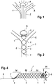
- Figure 1 shows a bifurcation aneurysm with an afferent vessel Z, two evacuating vessels X and Y and the aneurysm A arranged in the fork.
- the long arrows represent the blood flow that flows into the aneurysm A on the impact side and exerts an outward pressure there, below which the aneurysm expands (small arrows).
- FIG Figure 2 shows a vascular constellation with an aneurysm A, as in FIG Figure 1 described, with an implant 1 arranged therein.
- the implant has a proximal end 2 which has the coupling element
- the implant 1 is anchored to the vessel wall of the supplying vessel Z via its meshes 3 and has meshes 4 with a larger mesh size in the area of the bifurcation.
- a distal area 5 is shown in the neck of the aneurysm. Between the distal area 5 and the area with the enlarged meshes 4 there is a separation zone for retaining occlusion means introduced into the aneurysm A after the implant has been placed.
- the widened meshes 4 in the area of the bifurcation allow the blood stream flowing in via the supplying vessel Z to flow off into the branches X and Y without being significantly impeded.
- occlusion means (not shown here) have been placed in aneurysm A, the blood flow into aneurysm A is so obstructed that a plug is formed there and the aneurysm is shut down.
- Figure 3a shows schematically an implant and its division into individual sections.
- the implant 1 has a proximal section (a) in which the implant tapers and ends in a coupling element, shown here as a wire. This section corresponds to area 2 in Figure 2 .
- section (b) which is used to fix the implant to the vessel wall of the supplying vessel Z.
- This area has meshes 3 with a relatively narrow mesh size, which establish good contact with the vessel wall.
- the section (c) then follows distally, which has meshes 4 with a relatively large width. This area is intended to prevent blood flowing into the branches X and Y, see Figures 1 and 2 to submit.
- Section (d) can be an integral part of the implant, that is to say, together with sections (a) to (c), it can be cut from a tube (nitinol) or braided from such wires. But it is also possible to cut the sections (a) to (c) from a tube and to braid the section (d) and weld it to the section (c).
- the separating zone T1 which has one or more separating elements 6, is shown between sections (c) and (d). These separating elements can be clamped threads, wires or fibers, for example made of polyamide, but also parts of a cut structure that have been reshaped inward. This separation zone T1 with the separation elements 6 serves to hold back occlusion means placed in an aneurysm.
- the separation zone can also be shifted into section (d) or even be located at the distal end of section (d).
- a separation zone T2 is particularly useful when the bifurcation is transformed in such a way that the branching vessels X and Y do not branch off directly from the supplying vessel Z, but branch off from the aneurysm.
- the separation zone must be arranged directly above the branches in the widening section of the implant.
- the section (d) is limited to the distal end of the implant 1 and merges into the separation zone T2.
- FIG. 13 is an illustration of the implant essentially similar to that of FIG Figure 3a is equivalent to.
- the loops 12, which are only shown schematically here can form different angles to the longitudinal axis of the implant 1.
- the longitudinal axis is shown as a dashed line.
- the angle ⁇ can be very large (> 90 °, dashed illustration), which is particularly advantageous in the case of strongly bulged aneurysms, the bulge running at least partially in the proximal direction. In extreme cases, the angle ⁇ can be almost 180 °. In this way, the distal section (d) conforms well to the aneurysm wall.
- angle ⁇ is negative because part of the aneurysm wall is curved inward. It is important that the angles for the individual loops (12) can differ, which is of great advantage in the case of irregularly shaped aneurysms.
- proximal end 2 of section (a), at which the implant terminates in coupling wires via which the implant is connected to an insertion aid forms an angle ⁇ to the longitudinal axis of the implant. This angle may not be formed until after implantation. In this way, an improved expansion of the implant and the application to the blood vessel wall is promoted. Unwanted protrusion into the blood vessel is avoided.
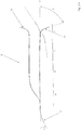
- FIG Figure 4 shows an implant 1 not according to the invention, as it is according to FIG Figure 2 can be used.
- the implant 1 is shown with a guide wire 9 and has a radiopaque marker coil 7 at its proximal end 2.
- the coupling element or elements via which the guide wire 9 is connected to the implant 1 are not shown, but are located in the area of the marker coil 7.
- the implant shown is a braid of individual wires, which are preferably made of nitinol and on which the final implant shape is impressed.
- nitinol allows the implant to be fed into a catheter in compressed form without losing its shape. After it has been released from the catheter, the implant assumes the shape impressed on it, so that it can fulfill its intended purpose.
- the implant 1 is divided into four sections (a) to (d), section (a) representing the tapering proximal section which converges in the proximal end 2 and ends in the coupling element or elements.
- Section (b) is a fixing section that comes to rest on the vessel wall of the supplying vessel Z.
- the section (c) is made permeable with meshes 4 through which the blood stream can exit into the branching vessels X and Y.
- Section (d) is opposite section (b) and here too opposite (c) expands and comes to rest in aneurysm A.
- the ends of the individual wires are atraumatically redesigned by marker coils 8 made of a radiopaque material, such as platinum or a platinum alloy.
- a fiber braid 6 which can be made of nylon, for example, and which at the same time represents the separation zone T1.
- the reference number 5 denotes the outwardly widening meshes or filaments of the implant 1 in the distal area.
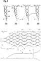
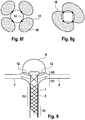
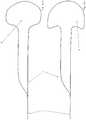
- Figure 5 shows four variants of the design of the distal area 5 of the implants 1 as a basic sketch.
- Figure 5a shows a distal end of the implant that widens in the shape of a trumpet, ie the section (d) widens in the shape of a cup.
- Figure 5b the distal end 5 is widened in the shape of a plate, with a very narrowly delimited distal section (d).
- Figure 5c shows a combination of the design elements of Figures 5a and 5b .
- Figure 5d finally shows a distal area with rolled-up distal ends of the individual filaments of an implant 1.
- FIG Figure 5a or 5b the sections (a), (b), (c) are shown.
- FIG. 6 shows an embodiment of an implant 1 with the sections (a) to (d) in a flatly spread out form.
- the implant 1 is to be understood as a mesh structure cut from nitinol tube, with the webs 11 shown in dashed lines corresponding to the extended webs on the opposite side in the illustration.
- the separating zone T1 with separating elements in the form of a drawn-in plane of nylon threads 6 is also shown there.
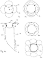
- Figure 7a shows an embodiment of the implant according to the invention in the view from the distal.
- the distal section (d) is formed by loops 12 which are expanded radially outward.
- the separation zone 6 is formed by a plane made of polymer threads or metallic fibers, which ensure that occlusion means introduced into the aneurysm do not leave it again.
- the Circle 14 symbolizes the transition into the cylindrical part of the implant.
- the loops are provided with radiopaque marker elements 13.
- the separation zone 6, i. H. the area framed as a square in the representation selected and the loops 12 also have a membrane which effectively blocks the flow of blood into the aneurysm.
- This membrane can be fixed to the polymer threads or the metallic fibers and the wires of the loops 12; in particular, polymer threads or metallic fibers can also be embedded in the membrane.
- the membrane can for example consist of polycarbonate urethane and be manufactured by means of electrospinning.
- the implant 1 is off Figure 7a shown from the side.
- Several loops 12, which have marker elements 13, can be seen in the distal area.
- the entrance to the aneurysm is blocked by the separation zone 6, it being possible here for crossing or interwoven polymer threads or metallic fibers which prevent the escape of occlusion means introduced into the aneurysm.
- the loops 12 and the separation zone 6 are provided with a membrane which largely cuts off the aneurysm from the blood flow. In this case, occlusion devices in the aneurysm can be dispensed with.
- the implant 1 has a radiopaque marker element 7 at the proximal end.
- FIG. 7c a further embodiment is shown with a membrane 24 in the separation zone 6, the membrane 24 extending in the proximal direction.
- the membrane 24 can in particular be conical or pyramidal, the apex of the cone / pyramid being proximal. In order to stretch such a membrane, it is useful to reinforce the membrane 24 with threads, wires or webs of the implant that hold the membrane 24 in the desired position.
- Figure 8 shows an implant 1 with a rather plate-shaped configuration of section (d), which essentially consists of wire loops 12.
- the wire loops adjoin the cylindrical part of the body of the implant 1, this cylindrical part being formed by sections (a) to (c).
- sections (a) to (c) In the transition area to the attached loops 12 there are marker elements 8 that are used for secure placement.
- the section (c) which allows the inflowing blood to escape into laterally outgoing vessels. The blood thus enters the outgoing vessels (X and Y, Fig. 2 ) one.
- FIG. 8b to 8g Individual variants of the distal section (d) are shown in the plan view in Figures 8b to 8g shown, wherein individual or multiple loops 12 can be provided with marker spirals 13.
- the marker spirals 13 can completely or partially surround the loops.
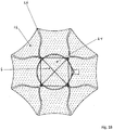
- the loops are based on four connecting webs 15 which also carry the marker elements 8, the inner circle 14 in the illustrations 9b to 9g representing the transition into the cylindrical part of the implant. Any existing tension in a separation zone T1 or T2 is not shown.
- FIGS. 8f and g show loops 12 provided with an expandable membrane 16, which in this case simultaneously form a separation zone T2, as in FIG Figure 3 shown.
- the Figure 8f also shows that the loops 12 can each be connected to the other areas of the implant via just one connection point.
- the separation zones T1 and T2 must divide the section of the aneurysm A to be occluded. Depending on the type of aneurysm, this separation zone is then in the entrance area - with branch vessels branching proximally from the entrance area - or within the aneurysm - when two vessels branch off from the aneurysm space itself - in the latter case only the part of the aneurysm free from branching vessels is occluded can be. In particular in the case of plate-shaped distal sections (d) of the implants In particular with a larger number of wire loops, there is no need for additional bracing or an arrangement of separating elements cut from the tube.
- the loop-shaped distal sections (d) shown can on the one hand, like the rest of the implant body, be cut from a tube with a suitable diameter. However, it is also possible to cut sections (a) to (c) of the implant body from a tube in the usual manner and to attach section (d) made of wire filaments, for example by laser welding.
- FIG 9 shows the special case of an aneurysm A, in which the branching vessels X and Y branch off from the aneurysm.
- the in Figure 8 described implants 1 are particularly suitable, in which the loops 12 simultaneously form the separation zone T2, which are arranged in the aneurysm itself distal from the branching vessels.
- the cylindrical body of the implant 1 with the sections (a) and (b) is located in the supplying vessel Z, the section (c), which allows the blood to pass through the branches X and Y, is located in the area of this branch and indirectly distal
- This section (c) is the section (d) with the loops 12.
- the loops are covered with a membrane, this membrane being made of an expandable material, for example Teflon, or a fiber fleece.
- Such a nonwoven made of polycarbonate urethane is from DE 28 06 030 known and is characterized by high elasticity, which is favorable for the application of the implant through a catheter.
- the membrane can be slotted, folded or designed to be porous, for example to save material and to facilitate transport through a catheter.
- Such a membrane can also be used as a separating element for the separating zone, as it is arranged between the sections (c) and (d).
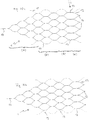
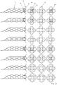
- Figure 10 shows several preferred embodiments of an implant 1 according to the invention in a two-dimensional form, in which the honeycomb structure is formed by essentially uniformly sized honeycombs; only the distal loops have a larger honeycomb area.
- the bars 11 shown in dashed lines correspond to the extended bars on the opposite side.
- the implant 1 thus corresponds to a tube with a lattice or honeycomb structure.
- the proximal section (a) connects to the proximally arranged coupling element 10, followed by the fixing section (b).
- the distal section (d) begins in the area of the eyelets 17, which are used to receive and fixate wire or nylon elements with which a separation zone is drawn into the implant.
- the distal loops in the outwardly widening section (d) have distal noses which have proven to be advantageous when the implant is introduced through a catheter at the place of use.
- Figure 10b corresponds in all essential points to the representation of Figure 10a , with the exception of a partial slot in the area of the arrows 19, where the tubular structure of the implant 1 is not closed.
- the slot runs parallel to the axis and ends in front of the distal section (d), where the permeable section (c) is located.
- Figure 10c shows a variant with a non-axially parallel slot 19 which winds around the longitudinal axis, but also ends in front of the distal section (d).
- Such slits have proven to be extremely advantageous for the flexibility in the area of the fixing zone (b).
- the radial force of the implant 1 is not significantly impaired as a result, but the adaptation to the vascular course and the vascular lumen is improved.
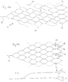
- Figure 10d also shows an implant with a slot, but the slot does not extend to the edges of the implant.
- Figure 10e shows a further variant with a slot 19, which also winds around the longitudinal axis, although honeycomb shapes exist side by side.
- the honeycomb shape has an influence on the flexibility and can be selected depending on the requirements.
- the loops or honeycombs of the distal section (d) are in Figure 10 each designated by the reference number 12.
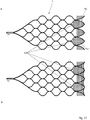
- FIG 11 shows a further variant of an implant 1 with a single coupling element 10 and an essentially regular honeycomb structure, in which additional loops 20 are provided as separating elements.
- the additional loops 20 are directed inward in the implanted product and form the separation zone T1.
- These loops 20 also have noses 18 which facilitate transport through a catheter.
- Figure 11b shows schematically the implant of Figure 11a with the inwardly pointing loops 20 and the separation zone T1.
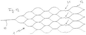
- Figure 12 shows a further variant of a particularly flexible implant 1 with joint connectors 21 in the form of a zigzag guide of the corresponding webs to improve the adaptation of the implant 1 to curved vessels in the area of the bifurcation.
- FIG 13a shows a further variant in which, as before, the webs 11 shown in dashed lines correspond to the extended webs on the opposite side.
- the embodiment is characterized in that the honeycomb structure is partially perforated, ie some honeycombs have interruptions 23 or gaps. It is possible to provide all of the honeycombs with interruptions 23, but in the present case only some honeycombs have an interruption 23. In addition, it is possible to vary between the sections. In the representation selected here, only the honeycombs in section (c), but not the honeycombs in section (b), have interruptions 23.
- the implant 1 is connected to the insertion aid via a coupling element 10.
- Figure 14a shows an embodiment of an implant 1 not according to the invention, which is characterized by the special design of the distal section (d), which is designed as a ball formed from individual wires or filaments.
- the sections (a) to (c) are designed as described above.
- the separation zone T1 with blocking elements as described above.
- a distally open basket can also be used for section (d).
- a braided structure is preferred for the ball or basket.
- FIG 15 shows a whole series of different embodiments of implants 1 according to the invention and not according to the invention in a side view and a view from the distal, in which membranes 16, 24 are provided.
- the membranes 16 fill the inside of the wire loops 12, the membrane 24 (partially) forms the separation zone 6, whereby the individual membranes 16, 24 can merge into one another or they can be a single wire loop 12, the separation zone 6 and possibly other areas Membrane can act.
- the area provided with a membrane 16, 24 is shown in dotted lines. As can be seen, areas outside of the wire loops 12 are also spanned with the membrane.
- the separation zone 6 can also have a membrane 24, this membrane being able to be supported by a thread structure, but this is not absolutely necessary.
- the inner surface of the wire loops 12 can be completely or partially filled with the membrane 16.
- embodiments are also possible in which the membrane 24 forming the separation zone 6 has openings 25 so that the membrane 24 is tight enough to prevent the escape of occlusion agents, but on the other hand a microcatheter is inserted through the opening 25 into the aneurysm can be used to place the occlusion device there. If threads / wires that cross one another are also provided in the area of the separation zone 6, a sufficient gap must remain to allow a catheter to be passed through.
- FIG 16 a similar representation of an alternative embodiment of the implant 1 according to the invention is shown, in which the membrane 24, which forms the separation zone 6, is oriented in a pyramid shape in the proximal direction.
- the membrane 24 is held by a thread structure which has a fixation proximal to the separation zone 6, in order in this way to bring about the pyramid shape.
- the membrane 24 is also drawn further proximally and collapses, which is associated with a low cross-sectional loading.
- an implant 1 is thus created which can be easily maneuvered through a suitable catheter.
- FIG 17 an embodiment is shown in which, similarly Figure 11 , the separation zone 6 is formed by wire loops 20 pointing into the interior.
- An unfolded implant structure in the side view was chosen as a representation.
- the wire loops 20, like the wire loops 12 pointing distally outward, are provided with a membrane 16, 24 provided, which further increases its tightness in the area of the separation zone 6.
- spaces between the wire loops 12 are also provided with a membrane 16.
- FIG 18 is a front view of an embodiment not according to the invention.
- the representation is similar to that in Figure 15 Struts 26 that are selected, instead of loops, are provided here, however, which point radially outward and form section (d).
- the struts 26 converge concentrically, two struts 26 each forming a unit and having a common origin at the distal end of the section (c).
- the struts 26 also serve to stretch a membrane 16, 24, shown in dotted lines, which extends both over the inner region of the separation zone and over the spaces between the struts 26. Additional stabilization can be provided by a thread structure 6 in the separation zone, but is not absolutely necessary. However, the thread structure 6 makes it easier to pierce individual segments of the inner membrane 24, while at the same time other areas of the membrane 24 remain undamaged, so that occlusion means can be introduced into the aneurysm.
Description
- Die Erfindung betrifft ein Implantat zum Einsatz bei der Okkludierung von Aneurysmen in Gefäßverzweigungen, insbesondere von Bifurkationsaneurysmen. Ein solches Implantat wird mit Hilfe eines Katheters und Führungsdrahts an den Implantationsort gebracht und dort dauerhaft implantiert. Entsprechend betrifft die Erfindung auch ein solches Implantat, implantationsfertig angekoppelt an einen Führungsdraht. Darüber hinaus betrifft die Erfindung ein Verfahren zur Einbringung des Implantats.
- Arteriovenöse Fehlbildungen können in einem Patienten zu erheblichen Beeinträchtigungen und Gefährdungen bis hin zum Tode führen. Dies gilt insbesondere auch für Aneurysmen, insbesondere dann, wenn sie im zerebralen Bereich auftreten. In der Regel versucht man derartige Fehlbildungen durch Implantate zu verschließen. Solche Implantate werden in der Regel auf endovaskulärem Weg mit Hilfe von Kathetern gesetzt.
- Insbesondere bei zerebralen Aneurysmen hat sich die Implantierung von Platinspiralen bewährt, die das Aneurysma mehr oder weniger vollständig ausfüllen, den Bluteinstrom weitgehend blockieren und dazu führen, dass sich ein lokaler Thrombus ausbildet, der das Aneurysma ausfüllt und letztlich verschließt. Diese Behandlungsmethode ist allerdings nur bei Aneurysmen geeignet, die über einen relativ engen Zugang zum Gefäßsystem verfügen, sogenannten Beerenaneurysmen. Bei Aussackungen von Blutgefäßen, die über einen weiten Zugang zum Gefäß verfügen, drohen die implantierten Spiralen wieder ausgeschwemmt zu werden. Diese können in andere Bereiche des Gefäßsystems gelangen und dort Schäden herbeiführen.
- In solchen Fällen wurde bereits vorgeschlagen, eine Art Stent zu setzen, der die Öffnung des Aneurysmas "vergittert" und dadurch die Ausschwemmung der Okklusionsspiralen verhindert. Derartige Stents, die über eine relativ weitmaschige Wandung verfügen, werden bereits bei einigen Formen von Aneurysmen eingesetzt.
- Dokumente
US 2007/198075 A1 ,DE 10 2008 028308 A1 undWO 2006/052322 A2 offenbaren vaskuläre Implantate zur Behandlung von Aneurysmen im Bereich von Gefäßverzweigungen. - Dokument
WO2012113554 A gehört zum Stand der Technik gemäß Art. 54 (3) EPÜ und betrifft ein Implantat zum Einsatz bei der Okkludierung von Aneurysmen im Bereich von Gefäßverzweigungen, insbesondere Bifurkationsaneurysmen, mit einer Maschenstruktur, welches - von proximal nach distal - die Abschnitte (a) bis (d) aufweist: (a) einen sich verjüngenden proximalen Abschnitt, in dem die Maschenstruktur zu einem oder mehreren Kupplungselementen zusammengeführt ist, (b) einen Fixierabschnitt, mit dem das Implantat an einer Gefäßwand abstützbar ist, (c) einen durchlässigen Abschnitt für den Bereich der Gefäßbifurkation und (d) einen distalen Abschnitt, in dem das Implantat gegenüber den Abschnitt (b) erweitert ist und der zur Platzierung im Aneurysma bestimmt ist, wobei im Bereich der Abschnitte (c) oder (d) eine Trennzone angeordnet ist. Der Abschnitt (d) besteht wesentlich aus mit einer dehnfähigen Membran versehene Drahtschlaufen. - Gefäßverzweigungen, insbesondere Gefäßbifurkationen, sind ein relativ häufiges Phänomen. Das durch eine Arterie im Bereich einer Gabelung auf die Stirnwand aufprallende Blut führt - im Fall einer Schwächung der Gefäßwandung - schnell zu einer Aussackung, die sich dann rasch erweitert. Solche Bifurkationsaneurysmen haben häufig einen weiten Hals, der eine Therapie nur mit Okklusionsspiralen unmöglich macht.
- Gleichzeitig fehlt es an Stentstrukturen, die geeignet sind, im Bereich einer Gefäßverzweigung eine "Vergitterung" des Aneurysmaeingangs herbeizuführen. Unter diesem Gesichtspunkt ist es Aufgabe der Erfindung, ein Implantat bereitzustellen, das geeignet ist, im Bereich insbesondere von Bifurkationsaneurysmen eingesetzt zu werden und dort den Eingang eines Aneurysmas zu "vergittern". Mit anschließend eingebrachten Okklusionsspiralen kann dann das Aneurysma stillgelegt werden.
- Eine solche "Vergitterung" ist auch im Sinne einer Beeinflussung des Blutstroms denkbar, um die Anzahl der Okklusionsspiralen zu reduzieren oder auf null zu setzen.
- Diese Aufgabe wird mit einem Implantat mit einer Maschenstruktur gelöst, welches - von proximal nach distal - die Abschnitte (b) bis (d) aufweist:
- einen Fixierabschnitt (b), mit dem das Implantat an einer Gefäßwand abstützbar ist,
- einen durchlässigen Abschnitt (c) für den Bereich der Gefäßverzweigung und
- einen distalen Abschnitt (d), in dem das Implantat gegenüber dem Abschnitt (b) radial erweitert ist und der zur Platzierung im Aneurysma bestimmt ist,
- wobei im Bereich der Abschnitte (c) oder (d) eine Trennzone angeordnet ist, die den Hals des Aneurysmas zumindest teilweise verschließt, der distale Abschnitt (d) eine Mehrzahl von mit dem Abschnitt (c) verbundenen Schlaufen aufweist und die Schlaufen zur Längsachse des Implantats einen Winkel zwischen -45° und +175° ausbilden, wobei ein positiver Winkel für nach radial außen und ein negativer Winkel für nach radial innen weisende Schlaufen steht und wobei die Trennzone eine oder mehrere Membranen aufweist, die das Innere der Schlaufen ausfüllen und Zwischenräume zwischen den Schlaufen überspannen.
- Die Begriffe "proximal" und "distal" sind so zu verstehen, dass sie zum Führungsdraht und somit zum Katheter und behandelnden Arzt weisende Teile des Implantats bezeichnen (proximal) bzw. vom Führungsdraht oder behandelnden Arzt weg weisende Teile (distal). Proximal ist damit führungsdrahtseitig und distal führungsdrahtabgewandt. Der Begriff "axial" bezieht sich auf die von proximal nach distal verlaufende Längsachse des Implantats, der Begriff "radial" auf hierzu senkrechte Ebenen.
- Bei dem erfindungsgemäßen Implantat handelt es sich um ein Implantat mit einer Maschenstruktur, die aus einem Geflecht einzelner Drähte bestehen kann, eine aus einem Rohr geschnittene Maschenstruktur aufweisen kann oder eine Kombination von beidem ist. Insoweit handelt es sich bei dem Implantat weitgehend um einen Stent oder ein stentähnliches Gebilde, das sich durch die besondere Art seines Einsatzes und Aufbaus auszeichnet. Im Falle der Flechtung aus einzelnen Drähten wird für die Abschnitte (b) und (c) eine Zahl von 4 bis 24 Drähten bevorzugt.
- Das erfindungsgemäße Implantat ist in mindestens drei, vorzugsweise vier Abschnitte gegliedert, nämlich die Abschnitte (a) bis (d), von proximal nach distal gesehen, wobei der Abschnitt (a) optional ist. Die Abschnitte (b) und (c) können auch gleich aufgebaut sein und sich lediglich hinsichtlich der Lage im Gefäß nach der Implantierung unterscheiden.
- Der Abschnitt (a) ist ein sich verjüngender proximaler Abschnitt, in dem die Maschenstruktur zu einem oder mehreren Kupplungselementen zusammengeführt ist. Die Kupplungselemente befinden sich vorzugsweise an der Peripherie, d. h. kommen im implantierten Zustand, wenn das Implantat in seiner expandierten Form vorliegt, an der Gefäßwandung zu liegen, und dienen der Verbindung mit einer Einführhilfe, insbesondere einem Führungsdraht. Eine zentrierte Anordnung ist auch aus applikationstechnischen Gründen nicht sinnvoll; die periphere Anordnung des oder der Kupplungselemente erleichtert bei Fehlplatzierungen das Rückziehen des Implantats in den Platzierungskatheter. Bevorzugt sind Ausführungsformen mit einem oder zwei Kupplungselementen. Vorzugsweise handelt es sich bei den Kupplungselementen um Kupplungsdrähte.
- Die Kupplungselemente, insbesondere die Kupplungsdrähte, bzw. das proximale Ende des Implantats (ohne Einführhilfe) können zur Längsachse des Implantats einen Winkel zwischen 0° und +60° ausbilden, wobei ein positiver Winkel für ein nach außen weisendes proximales Ende steht. Bevorzugt ist ein Bereich zwischen +10° und +30°, wobei der optimale Winkel von der Gestalt des Gefäßes abhängt. Ein solcher positiver Winkel erleichtert die optimale Expansion des Implantats und das Anlegen des proximalen Endes an das Trägergefäß; das Hineinragen des proximalen Endes in das Gefäßlumen, das den Blutfluss oder das Einführen eines weiteren Mikrokatheters stören könnte, wird wirkungsvoll verhindert. Vorzugsweise ist das proximale Ende des Implantats atraumatisch ausgebildet, um eine Verletzung der Gefäßwand auszuschließen. Die Ausbildung des Winkels ist erfindungsgemäß so zu verstehen, dass der Winkel nicht im unimplantierten Zustand vorliegen muss, es kommt vielmehr darauf an, dass das proximale Ende des Implantats einen solchen Winkel nach Implantation ausbildet, d. h. es ist ausreichend, dem Implantat eine entsprechende Verformung nach Implantation aufzuprägen. Hier bietet sich insbesondere die Verwendung von Formgedächtnismaterialien an.
- Abschnitt (b) ist ein Fixierabschnitt, mit dem sich das Implantat an der Gefäßwand des Blut heranführenden Gefäßes abstützt. In diesem Bereich ist das Gefäß nicht geschädigt und geeignet, mit einer Stentwandung beaufschlagt zu werden. Bei selbstexpandierenden Implantaten legt sich der Abschnitt (b) nach der Freisetzung aus dem Katheter selbständig an die Gefäßwandung an, bei ballonplatzierbaren Implantaten wird das Implantat in diesem Bereich durch einen Platzierungsballon aufgeweitet und gegen die Gefäßwand gepresst.
- Abschnitt (c) ist ein durchlässiger Abschnitt, der insbesondere eine größere Maschenweite als Abschnitt (b) aufweisen kann und der in den Bereich der eigentlichen Gefäßbifurkation gesetzt wird. Eine größere Maschenweite erlaubt einen mehr oder weniger ungehemmten Blutfluss durch die Maschen hindurch in die abführenden Gefäßzweige. Es ist jedoch nicht in jedem Fall erforderlich, im Abschnitt (c) eine größere Maschenweite vorzusehen; sofern dies nicht der Fall ist, können die Abschnitt (b) und (c) auch weitgehend oder vollständig identisch aufgebaut sein und sich nur hinsichtlich der Lage bei Einbringung in das Gefäßsystem unterscheiden.
- Der distale Abschnitt (d) ist gegenüber dem Abschnitt (b) und zumeist auch gegenüber dem Abschnitt (c) radial nach außen erweitert. Er dient der Platzierung im Aneurysma selbst, an dessen sich erweiternde Wandung er sich anpassen soll.
- Im Bereich der Abschnitte (c) und (d), insbesondere zwischen den Abschnitten (c) und (d) ist eine Trennzone angeordnet, die den Aneurysmenhals abdichtet. Die Trennzone dient insbesondere der Rückhaltung von in das Bifurkationsaneurysma eingebrachten Okklusionsmitteln. Im Falle einer hinreichend dichten Trennzone, die den Aneurysmenhals in ausreichendem Maße abdichtet, ist es aber auch denkbar, auf zusätzliche Okklusionsmittel wie Coils zu verzichten. Wichtig ist, dass letztlich im Aneurysma eine Blutgerinnung einsetzt. In jedem Fall steht die Trennzone in das Lumen des Implantats orthogonal zur Längsachse hinein. Die Abdeckungsrate des Aneurysmenhalses liegt zwischen 5 und 100 %, wobei Werte zwischen 30 und 60 % bevorzugt sind. Auf der einen Seite muss die Oberflächenabdeckung hinreichend groß sein, um in das Aneurysma eingebrachte Okklusionsmittel daran zu hindern, aus dem Aneurysma zu entweichen, oder durch ausreichendes Material eine dichte Oberfläche zu schaffen, auf der anderen Seite muss eine hinreichend große Flexibilität des Implantats erhalten bleiben, um es im Bereich des Bifurkationsaneurysmas einbringen zu können.
- Denkbar sind auch Ausführungsformen des Implantats, die keine Trennzone aufweisen, diese sind jedoch nicht als erfindungsgemäß aufzufassen. Ein solches Implantat kann eingesetzt werden, wenn mehr als ein Implantat in den Bereich des Bifurkationsaneurysmas eingebracht werden soll, insbesondere zwei Implantate. Dies kann von Vorteil sein, wenn das Aneurysma sehr unregelmäßig aufgebaut ist und in einem Teilbereich des Aneurysmas ein Verschluss herbeigeführt werden soll, in einem anderen Teilbereich hingegen der Blutfluss aufrecht erhalten werden muss, da sich Aneurysma und abgehendes Gefäß überschneiden. Bei dieser Variante bringt man zunächst ein Implantat ohne Trennzone ein, das im Übrigen vollständig dem beschriebenen Implantat entspricht. In einem zweiten Schritt wird durch das erste Implantat hindurch ein weiteres Implantat mit Trennzone eingebracht, um den Verschluss des Aneurysmas im gewünschten Umfang zu gewährleisten. Durch Einbringung von zwei aufeinander abgestimmten Implantaten kann den besonderen Anforderungen des Aneurysmas Rechnung getragen werden, beispielsweise wenn diese unterschiedliche distale Abschnitte (d) oder durchlässige Abschnitte (c) aufweisen.
- Die Erweiterung des Abschnitts (d) wird durch mit dem Abschnitt (c) verbundene Schlaufen gebildet. Die Erweiterung weist wenigstens zwei Schlaufen auf, insbesondere drei Schlaufen oder mehr. Typischerweise beträgt die Zahl der Schlaufen 2 bis 24, bevorzugt sind 2 bis 6. Bei den Schlaufen kann es sich um entsprechend geformte Drahtelemente handeln, sie können aber auch, soweit das Implantat aus einem Rohr geschnitten ist, entsprechend durch Laserschneiden des gleichen Rohrs erzeugt sein. Bei den Schlaufen handelt es sich vorzugsweise um vom Abschnitt (c) ausgehende, eine Schleife ausbildende und zurück verlaufende Drahtelemente, wobei grundsätzlich beliebig komplexe Formen für die Schlaufen denkbar sind. Insbesondere kann es sich auch um dreidimensionale Objekte handeln, je nachdem, wie die Schlaufen verlaufen. Schlaufen sind vorteilhaft, da sie weitgehend atraumatisch sind und die empfindliche Gefäßwand des Aneurysmas nicht verletzen. Die Erweiterung kann beispielsweise trompetenförmig, korbförmig oder in Form eines Geflechts vorliegen.
- Der Winkel, den die Schlaufen zur Längsachse des Implantats im implantierten Zustand ausbilden, liegt zwischen -45° und +175°, wobei ein positiver Winkel für nach radial außen und ein negativer Winkel für nach radial innen weisende Schlaufen steht. Im Falle von verhältnismäßig regelmäßigen Bifurkationsaneurysmen liegt der Winkel bevorzugt bei +45° bis +90°, teilweise treten jedoch auch Aneurysmen auf, die eine unregelmäßige Form aufweisen, insbesondere stark asymmetrisch sind. In solchen Fällen kann es sinnvoll sein, stark abweichende Winkel der Schlaufen zum Einsatz zu bringen. Beispielsweise kann es sinnvoll sein, den Winkel sehr groß zu wählen, wenn die Wandung in einem Bereich des Aneurysmas stark in Richtung des zuführenden Gefäßes ausgewölbt ist. In solchen Fällen sind Winkel > 90° sinnvoll. In anderen Fällen kann es zweckmäßig sein, einen Teil der Schlaufen nach innen weisen zu lassen, d. h. negative Winkel zu wählen, um sich an die Wandung des Aneurysmas anzupassen. Die Winkel, die die einzelnen Schlaufen ausbilden, können variieren, beispielsweise kann es bei einem asymmetrischen Aneurysma sinnvoll sein, einige Schlaufen mit Winkeln > 90° vorzusehen, während andere Schlaufen herkömmliche Winkel im Bereich zwischen 45° und 90° aufweisen. Wichtig ist, dass die genannten Winkel nach Implantierung ausgebildet werden, auch ein Implantat, bei dem im Zustand vor der Implantierung, etwa durch äußere Zwänge, sich die angegebenen Winkel noch nicht ausgebildet haben, ist daher als erfindungsgemäß anzusehen.
- Winkel, die die Schlaufen zur Längsachse des Implantats ausbilden, können z. B. zwischen 45° und 90°, -45° und 0°, 90° und 135° oder 135° und 175° liegen.
- Die Schlaufen im Abschnitt (d) können Fortsetzungen der den übrigen Implantatkörper ausbildenden Drähte oder Stege sein, es kann sich aber auch um gesonderte Drahtfilamente handeln, die im distalen Bereich des übrigen Implantatkörpers, d. h. am distalen Ende des Abschnitts (c) festgelegt sind, beispielsweise durch Laserverschweißen. Dabei kann jede Schlaufe des Abschnitts (d) an einem oder mehreren Verbindungspunkten mit dem weiteren Implantatkörper verbunden sein, insbesondere können auch nur ein oder zwei Verbindungspunkte pro Schlaufe vorgesehen sein.
- Gemäß einer alternativen, nicht erfindungsgemäßen Ausführungsform wird ein Implantat zum Einsatz bei der Okkludierung von Aneurysmen im Bereich von Gefäßverzweigungen, insbesondere Bifurkationsaneurysmen, mit einer Maschenstruktur zur Verfügung gestellt, welches - von proximal nach distal - die Abschnitte (b) bis (d) aufweist:
- einen Fixierabschnitt (b), mit dem das Implantat an einer Gefäßwand abstützbar ist,
- einen durchlässigen Abschnitt (c) für den Bereich der Gefäßverzweigung und
- einen distalen Abschnitt (d), in dem das Implantat gegenüber dem Abschnitt (b) radial erweitert ist und der zur Platzierung im Aneurysma bestimmt ist, wobei im Bereich der Abschnitte (c) oder (d) eine Trennzone angeordnet ist, die den Hals des Aneurysmas zumindest teilweise verschließt, und der distale Abschnitt (d) kugelförmig, pilzförmig, ankerförmig oder ellipsoidförmig erweitert ist. Vorzugsweise ist der distale Abschnitt (d) nicht zentral am Abschnitt (c) angebunden, sondern peripher. Abgesehen von der abweichenden Ausbildung des distalen Abschnitts (d) gilt für alle weiteren Aspekte des Implantats das zur Ausführungsform nach Anspruch 1 gesagte.
- Bei den genannten Formen handelt es sich um Alternativen, durch die ebenfalls ein radial erweiterter Abschnitt (d) ausgebildet werden kann. Ein kugelförmiger Abschnitt (d) kann sich beispielsweise gut an die Innenwandungen des Aneurysmas anschmiegen, da ein regelmäßiges Bifurkationsaneurysma häufig im Wesentlichen die Form einer Kugel aufweist. Dabei werden als Kugelform nicht nur exakte Kugeln entsprechend der geometrischen Definition verstanden, vielmehr werden auch hiervon abweichende, runde, dreidimensionale Formen erfindungsgemäß als Kugeln angesehen. In einigen Fällen ähnelt die Form des Abschnitts (d) auch einem Ellipsoid, wobei auch hier gilt, dass das Vorliegen eines exakten Rotationsellipsoids nicht erforderlich ist, um als ellipsoidförmig zu gelten. Weitere Möglichkeiten sind pilz- oder ankerförmige Abschnitte (d), die sich insbesondere bei unregelmäßigen Aneurysmen eignen, beispielsweise wenn die Wandung in einem Bereich des Aneurysmas stark in Richtung des zuführenden Gefäßes ausgewölbt ist. Dies wird dadurch gewährleistet, dass bei einer Pilz- oder Ankerform einige Bereiche des Abschnitts (d) in proximaler Richtung verlaufen. Dabei sei klargestellt, dass ein pilz- oder ankerförmiger Abschnitt selbst ebenfalls asymmetrisch sein, beispielsweise nur auf einer Seite in proximaler Richtung verlaufende Bereiche aufweisen kann. Sofern der Abschnitt (d) hinreichend oberflächendicht ist, kann er selbst die Trennzone ausbilden, auf gesonderte Vorrichtungen kann somit ggf. verzichtet werden. Der distale Abschnitt (d) kann lasergeschnitten oder auch geflochten sein, wobei bevorzugt 8 bis 128 Drähte zum Einsatz kommen.
- Die erfindungsgemäßen Implantate können aus herkömmlichen Stentmaterialien gefertigt sein, beispielsweise aus medizinischem Stahl oder Kobaltchromlegierungen bestehen, aber insbesondere aus Formgedächtnismaterial, etwa Nitinol oder ternären Nickeltitanlegierungen.
- Wie schon angesprochen, ist ein erfindungsgemäßes Implantat vorzugsweise zumindest partiell aus einem Rohr geschnitten, insbesondere aus einem Rohr aus einer Formgedächtnislegierung. Auch die Trennzone kann aus dem Rohr geschnitten sein.
- Die im erfindungsgemäßen Implantat vorgesehene Trennzone verläuft insbesondere zwischen den Abschnitten (c) und (d). In diesem Zusammenhang ist festzustellen, dass der Abschnitt (c) zumindest in seinem distalen Ende gegenüber dem Abschnitt (b) erweitert sein kann, was dann hilfreich ist, wenn das Bifurkationsaneurysma bereits Teile der abgehenden Blutgefäße eingenommen hat. In diesem Fall muss der Eingangsteil des Aneurysmas für den abzweigenden Blutstrom freigehalten werden, so dass die Trennzone im Aneurysma selbst verläuft. Der bereits erweiterte Bereich des Abschnitts (c) geht dann, ggf. unter weiterer Aufweitung, in den Abschnitt (d) über. Auch hier liegt die Trennzone zwischen den Abschnitten (c) und (d). Bei einer sehr flachen Ausgestaltung des Abschnitts (d) kann die Trennzone auch mit dem Abschnitt (d) zusammenfallen.
- Die Trennzone kann einerseits durch das Einziehen von Fasern, Fäden, dünnen Drähten, einer Membran oder dergleichen Trennelemente ausgebildet werden, kann aber auch integraler Teil des Implantats in dem Sinne sein, dass es sich um aus dem Ausgangsrohr herausgeschnittene und entsprechend umgeformte Trennelemente oder um aus einem Drahtgeflecht gebildete Trennelemente, etwa Schlaufen oder Stege, handelt. Im Falle von Schlaufen oder Stegen weisen diese radial nach innen in das Lumen des Implantats, im Gegensatz zu Schlaufen des distalen Abschnitts (d), die zumindest größtenteils nach außen weisen. Damit die nach innen weisenden Schlaufen/Stege sich nicht gegenseitig behindern, kann es sinnvoll sein, diese asymmetrisch auszugestalten. Die Zahl kann variieren, abhängig von der Struktur des Implantats und der Anzahl der Waben.
- Die die Trennzone ausbildenden Fäden können aus einem Polymermaterial hergestellt sein, beispielsweise einem Polyamid wie Nylon (Polyhexamethylenadipinsäureamid). Ebenso möglich ist die Herstellung aus Metall, wobei Formgedächtnislegierungen bevorzugt sind, insbesondere Nickel-Titan-Legierungen wie Nitinol.
- Eine weitere Möglichkeit besteht darin, in der Trennzone eine Membran vorzusehen, die weitgehend oder vollständig undurchlässig für Blut ist und das Aneurysma auf diese Weise vom Blutstrom abkoppelt. Sofern eine weitgehend vollständige Abkopplung vom Blutstrom erreicht wird, ist eine Einbringung von Okklusionsmitteln in das Aneurysma u. U. entbehrlich, d. h. die Trennzone dient in diesem Fall nicht zum Zurückhalten von Okklusionsmitteln. Die Membran kann auf ein Geflecht aus Fäden oder Drähten aufgespannt sein, bspw. können Fäden oder Drähte eine Struktur bilden, über oder auf die die Membran aufgespannt ist. Zusätzlich sind weitere, z. B. kreuzförmig verlaufende Fäden/Drähte denkbar, die ein Fadenkreuz ausbilden. Fäden oder Drähte sind jedoch nicht unbedingt erforderlich, auch ein Überspannen der Trennzone ohne zusätzliche Fäden/Drähte ist möglich.
- Es kann jedoch von Vorteil sein, zusätzlich Okklusionsmittel in das Aneurysma einzubringen. Aus diesem Grund kann es sinnvoll sein, für die Trennzone eine Membran mit einer oder mehreren Ausnehmungen zu verwenden, so dass durch die Ausnehmung ein Einbringen von Okklusionsmitteln, insbesondere Coils möglich ist. Die Ausnehmung sollte eine Größe aufweisen, dass ein Katheter durch die Ausnehmung in den Bereich des Aneurysmas vorgeschoben werden kann, wobei durch den Katheter die Okklusionsmittel eingebracht werden. Andererseits sollte die Ausnehmung den Aneurysmenhals so weit abdecken, dass die Okklusionsmittel das Aneurysma nicht unkontrolliert verlassen können, wobei ggf. die Trennzone überspannende Fäden/Drähte eine zusätzliche Rückhaltefunktion erfüllen. Selbstverständlich dürfen in diesem Fall die Fäden bzw. Drähte nur so dicht verlaufen, dass ein Hindurchführen eines Katheters und ein Einbringen von Okklusionsmitteln weiterhin möglich sind.
- Um Okklusionsmittel in das Aneurysma einzubringen, kann die die Trennzone überspannende Membran auch partiell durchstoßbar ausgebildet werden, wobei zum Durchstoßen typischerweise ein Mikrokatheter oder ein Führungsdraht verwendet wird. Durch die so geschaffene Öffnung wird sodann ein Mikrokatheter geführt, durch den die Okklusionsmittel eingeschoben werden. Die Membran sollte so beschaffen sein, dass sie auch nach Durchstoßen partiell erhalten bleibt, so dass die Okklusionsmittel weiterhin durch die Membran am Wiederaustritt gehindert werden. Beispielsweise können in der Trennzone vorgesehene Fäden oder Drähte, die in der Form eines Fadenkreuzes aufgespannt sein können, dafür sorgen, dass lediglich ein Segment der Membran beim Durchstoßen eine Öffnung ausbildet, während die übrigen Segmente von der Membran abgedeckt bleiben, da die Randbereiche der Membran von den Fäden/Drähte stabilisiert und vor einem Einreißen geschützt werden. Bei der die Trennzone überspannenden Membran kann es sich um eine einzelne Membran handeln, die nur partiell durchstoßen wird, oder auch um mehrere kleine Membranen.
- Im Inneren der den Abschnitt (d) bildenden (Draht)schlaufen sind Membranen vorgesehen. Sofern sowohl in der Trennzone als auch im Inneren der Schlaufen Membranen vorgesehen sind, erleichtert dies die Fixierung der Membran.
- Die Membran muss nicht auf die Trennzone und das Innere der Schlaufen beschränkt sein, sondern kann insgesamt Trennzone und Schlaufen überspannen, wobei die Schlaufen zur Fixierung der Membran dienen können. Membranen sind auch in den Zwischenräumen zwischen den Schlaufen vorgesehen.
- Zur Abgrenzung und Verstärkung der Membran können auch zwischen den einzelnen Schlaufen gespannte Fäden dienen, d. h. die Membranen werden zumindest teilweise seitlich von einem oder mehreren Fäden begrenzt, die die Schlaufen miteinander verbinden. Dabei muss die Begrenzung der jeweiligen Membran nicht in jeder Richtung über einen Faden erfolgen, hierzu können auch teilweise die Schlaufen selbst dienen. Beispielsweise kann der äußere Rand der Membran, der häufig auch weiter distal liegt, durch Fäden, der innere Rand durch Schlaufen umrandet sein. Im Vergleich zu einer Membran ohne seitliche Begrenzung wird insbesondere ein zusätzlicher Schutz der Membran gegen Beschädigungen und Risse erreicht. Die Fäden werden bevorzugt aus einem Polyamid wie Nylon gefertigt.
- Ein Vorteil der Verwendung einer Membran im Bereich der Trennzone ist darin zu sehen, dass diese sich bei der Platzierung des Implantats im Katheter eng nach distal oder proximal zusammenlegt, so dass ein Implantat mit im expandierten Zustand weitgehend dichter Trennzone zur Verfügung gestellt wird, das sich im kontrahierten Zustand auch durch enge Blutgefäße gut hindurchführen lässt. Im Übrigen bleibt der Aufbau des Implantats im Vergleich zu einem Implantat ohne Trennzone weitgehend unverändert.
- Die Membran kann aus einem Polymermaterial wie Polytetrafluorethylen, Polyester, Polyamiden, Polyurethanen oder Polyolefinen hergestellt sein. Besonders bevorzugt sind Polycarbonaturethane. Wünschenswert ist insbesondere eine integrale Verbindung der Membran mit den die Trennzone ausbildenden Fäden oder Drähten. Diese kann durch eine Tauch- oder Sprühbeschichtung der Fäden/Drähte herbeigeführt werden.
- Vorzugsweise wird die Membran durch Elektrospinnen erzeugt. Hierbei werden Fibrillen bzw. Fasern aus einer Polymerlösung mit Hilfe von elektrischem Strom auf einem Substrat abgeschieden. Bei der Abscheidung verkleben die Fibrillen zu einem Vlies. In der Regel haben die Fibrillen einen Durchmesser von 100 bis 3000 nm. Durch Elektrospinnen gewonnene Membranen sind sehr gleichmäßig ausgebildet und können eine Grundstruktur aus Fäden oder Drähten in sich einzuschließen. Die Membran ist zäh und mechanisch belastbar und kann mechanisch durchstoßen werden, ohne dass die Öffnung zum Ansatzpunkt für weitergehende Risse wird. Die Dicke der Fibrillen wie auch der Grad der Porosität kann durch Auswahl der Verfahrensparameter gesteuert werden. Im Zusammenhang mit der Schaffung der Membran und den dafür geeigneten Materialien wird insbesondere auf die
WO 2008/049386 , dieDE 28 06 030 A1 und die darin genannte Literatur hingewiesen. - Vorteilhaft ist auch ein Implantat, bei dem die Trennzone durch eine an der Innenseite des Implantats anliegende Membran gebildet wird, wobei diese Membran wiederum mit weiteren äußeren Membranabschnitten fest verbunden ist, die die einzelnen Schlaufen ausfüllen. Eine solche Membranstruktur lässt sich über Elektrospinnen erzeugen. Die innere und äußere Membranschicht sind in diesem Fall teilweise verbunden; dort, wo die innere Membranschicht keine Verbindung mit der äußeren Membranschicht aufweist, zieht sie sich ähnlich einem Nylonstrumpf zusammen und bildet somit eine passierbare Trennzone aus.
- Statt durch Elektrospinnen kann die Membran auch über einen Tauchprozess hergestellt werden.
- Die Membran muss nicht in jedem Fall in einer Ebene orthogonal zur Längsachse des Implantats verlaufen, sondern kann auch eine Ausrichtung in Richtung proximal aufweisen. In diesem Fall ist die Membran zwar in ihrem Randbereich im Umfang des Implantats fixiert, der mittlere Bereich der Membran erstreckt sich aber in proximaler Richtung. Es ergibt sich somit insgesamt eine Kegel- oder Pyramidenform, wobei die Basis des Kegels/der Pyramide orthogonal zur Längsachse orientiert und die Membran im Randbereich mit dem Implantat verbunden ist, während der Scheitel des Kegels/der Pyramide weiter proximal liegt. Der Blutstrom wird, wenn er auf die Membran trifft, auf diese Weise geteilt und seitwärts abgelenkt, so dass der Blutstrom in das Aneurysma weitgehend zum Erliegen kommt.
- Auch im Falle einer Kegel-/Pyramidenform der die Trennzone ausbildenden Membran kann diese eine oder mehrere Ausnehmungen aufweisen, damit weiterhin nach Platzierung des Implantats durch die Ausnehmung hindurch Okklusionsmittel in das Aneurysma eingebracht werden können.
- Um die Kegel-/Pyramidenform der Membran dauerhaft zu erhalten, sollte die Membran auf einer Gerüststruktur aus Fäden oder Drähten fixiert sein, wobei es sich prinzipiell auch um Stege handeln kann, die aus der das Implantat ausbildenden Struktur z. B. mit Hilfe eines Lasers herausgeschnitten sind. Dabei sollte darauf geachtet werden, dass die Fäden/Drähte eine hinreichende Steifigkeit aufweisen, um eine Umorientierung oder Umstülpung der Membran aufgrund des Blutdrucks zu verhindern. Ggf. müssen hierfür zusätzliche Fäden oder Drähte eingebracht werden.
- Eine Möglichkeit besteht darin, ein Fadenkreuz aus zwei relativ langen Einzelfäden zu erzeugen, an dem die Membran fixiert ist, wobei aufgrund der Länge der Einzelfäden die Membran zunächst nicht gespannt ist. Ein oder mehrere Fäden können darüber hinaus an einer weiter proximal liegenden Schlaufe des Implantats fixiert sein, so dass das Fadenkreuz und damit die Membran in Richtung proximal gespannt werden, sobald das Implantat gestreckt wird. Selbstverständlich muss es sich nicht um lediglich zwei Fäden handeln, die ein Fadenkreuz ausbilden, ebenso denkbar sind nahezu beliebige andere Fadengeflechte, die eine Art Gerüststruktur ausbilden, um der Membran eine Struktur aufzuprägen.
- Allgemein ist für die Erfindung wesentlich, dass die Trennzone ihre Funktion erfüllt, nämlich in das Aneurysma eingeführte Okklusionsmittel, etwa Okklusionsspiralen, zuverlässig zurückzuhalten oder den Blutstrom so abzulenken, dass weitere Okklusionsmittel unnötig sind. Die Trennzone verläuft orthogonal zur Längsachse des Implantats, wobei die die Trennzone ausbildenden Fasern, Fäden, Drähte etc. im Wesentlichen in einer Ebene liegen können.
- Wird die Trennzone durch das Einziehen von Fasern, Fäden oder dünnen Drähten ausgebildet, ist die Anordnung von Ösen im Bereich der Trennzone zweckmäßig. Beispielsweise können die Maschen des Abschnitts (d) mit entsprechenden Ösen ausgestattet sein, in die Fäden kreuz- oder sternförmig eingeknotet werden. Die Ösen selbst können aus einem Fasermaterial gefertigt sein. Die Fäden/Fasern bestehen z. B. aus einem geeigneten Polymer wie einem Polyamid (Nylon) oder es handelt sich um metallische Fasern.
- Die Trennzone kann aber auch durch aus einem Rohrmaterial geschnittene Bögen oder aus (Draht)schlaufen gebildet werden, wobei die Maschen des Abschnitts (d) nach außen umgeformt werden und die Bögen/Schlaufen der Trennzone in den Implantatkörper hinein umgebogen sind. Mindestens ein Bogen/eine Schlaufe ist erforderlich. Bei zwei bis vier Bögen/Schlaufen bilden diese ein stabiles Trennelement, das in ein Aneurysma eingebrachte Okklusionsmittel zuverlässig zurückhält.
- Die Schlaufen können eine Wabenform aufweisen. Beim Kontrahieren des Implantats werden die Schlaufen typischerweise nach proximal gestreckt und legen sich an die weiteren Filamente des Implantats an, so dass sich das Implantat problemlos durch einen Katheter bewegen lässt.
- Der distale Abschnitt (d) des erfindungsgemäßen Implantats ist insbesondere atraumatisch, weich und elastisch ausgebildet. Die Wandungen von Aneurysmen sind empfindlich und können bei Belastung reißen, was unter allen Umständen verhindert werden muss. Entsprechend muss insbesondere der distale Abschnitt (d) des erfindungsgemäßen Implantats atraumatisch gestaltet sein. Dies wird beispielsweise mit der Anordnung von Schlaufen erreicht, die sich dort, wo sie Kontakt mit der Aneurysmawandung bekommen, sanft an diese anschmiegen. Solche Schlaufen können, wie andere Bereiche des Implantats auch, durch Laserschneiden aus einem Rohr generiert, mittels angehefteter Drähte, die beispielsweise mit dem Abschnitt (c) laserverschweißt sind, oder aus einem einheitlichen Drahtgeflecht erzeugt werden. Diese Übergangszone deckt sich insbesondere mit der Trennzone, kann aber auch einen erweiterten Bereich des Abschnitts (c) darstellen, mit distal davon angeordneter Trennzone.
- In jedem Fall ist es von Bedeutung, im distalen Abschnitt (d) alle Drahtenden atraumatisch auszubilden, um eine Perforation der Aneurysmawand zu verhindern.
- Die Maschen im distalen Abschnitt (d) können als gerundete Bögen enden, insbesondere am distalen Ende aber auch Nasen (Vorsprünge) aufweisen, welche naturgemäß aber ebenfalls gerundet und atraumatisch sind. Diese Nasen haben den Effekt, dass sich das Implantat in der gestreckten Form im Katheter einfacher, d. h. mit geringerem Kraftaufwand, verschieben lässt.
- Die erfindungsgemäßen Implantate können durchgängig die Form eines aus der Maschenstruktur gebildeten seitlich geschlossenen Rohrs haben, jedoch auch seitlich partiell oder durchgehend geschlitzt sein. Die Schlitzung kann achsparallel verlaufen oder schräg-/helixförmig. In solch einem Fall ist in den geschlitzten Bereichen die Maschenstruktur entsprechend der Gefäßform gerollt, etwa in der Form eines gerollten Segments eines Maschendrahtzauns. Bei der Implantation eines solchen geschlitzten Implantats erlaubt dies eine gute Anpassung an das Gefäßlumen, insbesondere des zuführenden Gefäßes, wobei eine geringfügige Unter- oder Überdeckung der seitlichen Ränder der Maschenstruktur in der Regel unproblematisch ist.
- Möglich ist beispielsweise eine partielle Schlitzung, die am distalen Abschnitt (d) endet. Eine solche Schlitzung erlaubt eine gute Anpassung an den Gefäßverlauf, insbesondere im Bereich der Abschnitte (a) bis (c), und führt damit zu einer guten Fixierung des Implantats im Gefäß. Überraschend hat sich gezeigt, dass die Schlitzung keinen negativen Einfluss auf die Radialkraft ausüben muss.
- Es ist möglich, zumindest einige Maschen des Implantats mit Unterbrechungen zu versehen, d. h. die Maschen sind zum Teil nicht vollständig geschlossen. Ein solches Open-Cell-Design weist eine höhere Flexibilität auf, was bei stark gewundenen Blutgefäßen von Vorteil sein kann. Darüber hinaus bewirkt das Fehlen von Stegen/Streben einen verbesserten Blutfluss im Bereich der Gefäßverzweigung. Allerdings wird der Vorteil der erhöhten Flexibilität damit erkauft, dass sich ein Implantat mit Open-Cell-Design schlechter in den Mikrokatheter zurückziehen lässt, wenn sich dies bei der Einführung als notwendig herausstellen sollte. Aus diesem Grund kann bei einer solchen Ausführungsform die proximale Anbindung an eine Einführhilfe über den Abschnitt (a) entfallen. Ein alternatives Einfuhrsystem kann beispielsweise so aussehen, dass das im Mikrokatheter radial komprimierte Implantat auf einem Draht zwischen zwei Nocken lagert und sich bei Entfernung des Mikrokatheters selbständig entfaltet und dadurch vom Einfuhrsystem löst.
- Die erfindungsgemäßen Implantate weisen in der Regel röntgendichte Markerelemente auf, die die Visualisierung und Platzierung am Implantationsort erleichtern. Solche Markerelemente sind beispielsweise im Bereich des distalen Endes des Abschnitts (d) angeordnet, wobei sie bei zusammengeführten Drähten die Verbindungspunkte atraumatisch umformen können. Solche Markerelemente können auch in Form von Drahtwicklungen, als Manschetten und als geschlitzte Rohrabschnitte vorliegen, die auf das Implantat aufgecrimpt werden, beispielsweise im Übergangsbereich der Abschnitte (c) und (d) oder auf den Drahtschlaufen des Abschnitts (d). Für die Markerelemente kommen als Materialien insbesondere Platin und Platinlegierungen in Frage, beispielsweise eine Legierung aus Platin und Iridium, wie sie vielfach im Stand der Technik für Markerzwecke und als Material für Okklusionscoils eingesetzt wird. Idealerweise ist der distale Abschnitt (d) und sind insbesondere die Schlaufen vollständig oder teilweise röntgendicht, d. h. röntgensichtbar ausgebildet.
- Möglich ist es auch, röntgensichtbare Substanzen in die Membranen einzubringen. Hierbei kann es sich um röntgensichtbare Partikel handeln, wie sie üblicherweise in der Röntgentechnik als Kontrastmittel eingesetzt werden. Solche röntgendichten Substanzen sind beispielsweise Schwermetallsalze wie Bariumsulfat oder lodverbindungen. Die Röntgensichtbarkeit der Membran ist bei der Einbringung und Lokalisierung des Implantats hilfreich und kann zusätzlich oder anstelle von Markerelementen Verwendung finden.
- Ggf. kann ein Teil der Waben des Implantats von Stegen mit dünnerem Querschnitt gebildet werden, um die Flexibilität des Implantats zu erhöhen. Der Bereich liegt vorzugsweise im Abschnitt (b) und soll einem nicht regelmäßigen Verlauf des Blutgefäßes in der Fixierzone Rechnung tragen.
- Die Implantate müssen keine rohrförmige Struktur haben, sondern können auch als gerollte "Matten" vorliegen, die sich gegen die Gefäßwand aufspannen. Auch eine partielle Schlitzung ist möglich.
- Die Erfindung betrifft schließlich ein Implantat nach der vorstehenden Beschreibung, das an einen üblichen Führungsdraht angekoppelt ist. Diese Ankopplung kann beispielsweise durch Verbindungselemente erfolgen, die sich unter Einwirkung von elektrischem Strom elektrolytisch auflösen. Solche Verbindungselemente und Materialien sind insbesondere für die Ablösung von Okklusionsspiralen und Stents vielfach beschrieben. Auch eine mechanische Ablösung durch Kupplungselemente ist ohne Weiteres möglich, wobei die Kupplungselemente mit entsprechend angepassten Kupplungsteilen des Führungsdrahts zusammenwirken. Unter dem äußeren Zwang eines Katheters oder einer Hülle bleibt diese Verbindung intakt; nach Herausschieben des Implantats und der Kupplungsstelle aus dem Katheter oder der Umhüllung löst sich aber die Verbindung und setzt das Implantat mit den zum Implantat gehörigen Kupplungselementen frei.
- Die Erfindung betrifft auch die Platzierung der erfindungsgemäßen Implantate im Blutgefäßsystem. Dies kann mit Hilfe eines üblichen Katheters oder Mikrokatheters erfolgen; diese Technik ist allgemein erprobt und wird vielfach angewandt. Sofern die Trennzone nicht bereits selbst für eine ausreichende Abdichtung des Aneurysmenhalses sorgt, werden nach Platzierung des Implantats Okklusionsmittel in das Aneurysma eingebracht. Hierzu wird das distale Ende eines Mikrokatheters durch die Trennzone hindurch in das Aneurysma geführt und die Okklusionsmittel, insbesondere Coils werden freigesetzt. Anschließend wird der Mikrokatheter zurückgezogen, die Okklusionsmittel werden durch das Implantat daran gehindert, aus dem Aneurysma zu entweichen. Neben herkömmlichen Okklusionsmitteln wie Coils können auch in anderer Weise geformte Körper zum Verschließen von Aneurysmen eingebracht werden, beispielsweise geflochtene oder auf andere Weise geformte Kugelkörper.
- Die Erfindung wird durch die beiliegenden Abbildungen näher erläutert. Es zeigen:
- Figur 1
- als Prinzipskizze ein Bifurkationsaneurysma;
- Figur 2
- erfindungsgemäßes schematisch ein nicht Implantat, implantiert in den Bereich einer Gefäßverzweigung mit Bifurkationsaneurysma;
- Figur 3a
- das Implantat mit seinen Sektionen als Prinzipdarstellung;
- Figur 3b
- eine weitere Prinzipdarstellung des Implantats
- Figur 4
- ein nicht erfindungsgemäßes Implantat, wie es gemäß
Figur 2 eingesetzt werden kann; - Figur 5
- Varianten für den Abschnitt (d) eines Implantats;
- Figur 6
- eine Ausführungsform eines Implantats, flächig ausgebreitet;
- Figur 7a
- ein Implantat mit schlaufenförmigen distalen Abschnitten (d) in einer Ansicht von distal;
- Figur 7b
- das Implantat aus
Figur 7a in einer Seitenansicht; - Figur 7c
- ein nicht erfindungsgemäßes Implantat mit einer Membran in der Trennzone, die sich in Richtung proximal erstreckt;
- Figur 8
- weitere Varianten eines nicht erfindungsgemäßenImplantats mit schlaufenförmigen distalen Abschnitten (d);
- Figur 9
- ein Bifurkationsaneurysma mit aus dem Aneurysmabereich abzweigenden Seitengefäßen und einem implantierten Implantat;
- Figur 10
- in flächig ausgebreiteter Form Varianten Implantate;
- Figur 11
- eine weitere Variante mit einwärts- und auswärtsweisenden Bögen im Abschnitt (d);
- Figur 12
- eine weitere Variante mit Gelenkverbindern im Abschnitt (c);
- Figur 13
- eine weitere Variante eines Implantats mit erhöhter Flexibilität;
- Figur 14
- alternative Ausführungsformen von nicht erfindungsgemäßen Implantaten;
- Figur 15
- verschiedene Varianten von erfindungsgemäßen und nicht erfindungsgemäßen Implantaten in der Seitenansicht und in der Frontalansicht;
- Figur 16
- eine weitere Variante des erfindungsgemäßen Implantats in der Seitenansicht und in der Frontalansicht;
- Figur 17
- weitere Varianten des erfindungsgemäßen Implantats in flächig ausgebreiteter Form und
- Figur 18
- eine weitere Variante eines nicht erfindungsgemäßen Implantats in der Frontalansicht.
-
Figur 1 zeigt ein Bifurkationsaneurysma mit einem zuführenden Gefäß Z, zwei abführenden Gefäßen X und Y sowie dem in der Gabelung angeordneten Aneurysma A. Die langen Pfeile stellen den Blutstrom dar, der auf der Prallseite in das Aneurysma A einfließt und dort einen Druck nach außen ausübt, unter dem das Aneurysma sich erweitert (kleine Pfeile). -
Figur 2 zeigt eine Gefäßkonstellation mit einem Aneurysma A, wie inFigur 1 beschrieben, mit einem darin angeordneten Implantat 1. Das Implantat hat ein proximales Ende 2, das das Kupplungselement aufweist - und vor der Ablösung in den Führungsdraht (nicht dargestellt) übergeht. Das Implantat 1 ist über seine Maschen 3 an der Gefäßwand des zuführenden Gefäßes Z verankert und weist im Bereich der Bifurkation Maschen 4 mit einer größeren Maschenweite auf. Im Hals des Aneurysmas ist ein distaler Bereich 5 dargestellt. Zwischen dem distalen Bereich 5 und dem Bereich mit den erweiterten Maschen 4 befindet sich eine Trennzone zur Rückhaltung von in das Aneurysma A nach Setzen des Implantats eingeführten Okklusionsmitteln.
- Die erweiterten Maschen 4 im Bereich der Bifurkation erlauben es dem über das zuführende Gefäß Z einfließenden Blutstrom, in die Abzweigungen X und Y abzufließen, ohne groß behindert zu werden. Nach Setzen von hier nicht dargestellten Okklusionsmitteln im Aneurysma A ist der Blutstrom in das Aneurysma A so behindert, dass es dort zur Ausbildung eines Pfropfens und damit zur Stilllegung des Aneurysmas kommt. Alternativ kommt es zur Okklusion ohne Okklusionsmittel, sofern die Trennzone hinreichend dicht ist.
-
Figur 3a zeigt schematisch ein Implantat und seine Aufteilung in einzelne Abschnitte. - Das Implantat 1 hat einen proximalen Abschnitt (a), in dem sich das Implantat verjüngt und in einem Kupplungselement endet, hier als Draht dargestellt. Dieser Abschnitt entspricht dem Bereich 2 in
Figur 2 . - Daran schließt sich distal der Abschnitt (b) an, der der Fixierung des Implantats an der Gefäßwand des zuführenden Gefäßes Z dient. Dieser Bereich hat Maschen 3 mit einer relativ engen Maschenweite, die einen guten Kontakt zur Gefäßwandung herstellen.
- Distal schließt sich dann der Abschnitt (c) an, der Maschen 4 mit einer relativ großen Weite aufweist. Dieser Bereich ist dazu bestimmt, einströmendes Blut in die Abzweigung X und Y, siehe
Figur 1 und 2 , abzugeben. - Das distale Ende des Implantats 1 ist der Abschnitt (d), in dem sich die Struktur 5 im gezeigten Fall trompetenförmig erweitert. Dieser Bereich kommt in dem Aneurysma A zu Liegen. Der Abschnitt (d) kann integraler Bestandteil des Implantats sein, d. h. zusammen mit den Abschnitten (a) bis (c) aus einem Rohr (Nitinol) geschnitten oder aus solchen Drähten geflochten sein. Es ist aber auch möglich, die Abschnitte (a) bis (c) aus einem Rohr zu schneiden und den Abschnitt (d) zu flechten und mit dem Abschnitt (c) zu verschweißen.
- Zwischen den Abschnitten (c) und (d) ist die Trennzone T1 dargestellt, die ein oder mehrere Trennelemente 6 aufweist. Bei diesen Trennelementen kann es sich um eingespannte Fäden, Drähte oder Fasern, etwa aus Polyamid, handeln, aber auch um Teile einer geschnittenen Struktur, die nach innen umgeformt wurden. Diese Trennzone T1 mit den Trennelementen 6 dient dazu, in ein Aneurysma hinein platzierte Okklusionsmittel zurückzuhalten.
- Je nach Art des Aneurysmas kann die Trennzone auch in den Abschnitt (d) hinein verschoben sein oder sich sogar am distalen Ende des Abschnitts (d) befinden. Eine solche Trennzone T2 ist insbesondere dann sinnvoll, wenn die Bifurkation so umgewandelt ist, dass die abzweigenden Gefäße X und Y nicht direkt vom zuführenden Gefäß Z abzweigen, sondern aus dem Aneurysma abzweigen. In diesem Fall muss die Trennzone unmittelbar oberhalb der Abzweigungen im sich erweiternden Abschnitt des Implantats angeordnet sein. Der Abschnitt (d) ist auf das distale Ende des Implantats 1 beschränkt und geht in die Trennzone T2 über.
-
Figur 3b ist eine Darstellung des Implantats, die im Wesentlichen der ausFigur 3a entspricht. Darüber hinaus erkennt man, dass die hier nur schematisch wiedergegebenen Schlaufen 12 unterschiedliche Winkel zur Längsachse des Implantats 1 ausbilden können. Die Längsachse ist als gestrichelte Linie dargestellt. Der Winkel β kann sehr groß sein (> 90°, gestrichelte Darstellung), was insbesondere bei stark ausgewölbten Aneurysmen von Vorteil ist, wobei die Auswölbung zumindest partiell in Richtung proximal verläuft. In Extremfällen kann der Winkel β nahezu 180° betragen. Auf diese Weise wird eine gute Anschmiegung des distalen Abschnitts (d) an die Aneurysmenwand erreicht. - In anderen Fällen (ebenfalls gestrichelt dargestellt) kann es von Vorteil sein, wenn der Winkel β negativ ist, weil ein Teil der Aneurysmenwand nach innen gekrümmt ist. Wichtig ist, dass die Winkel für die einzelnen Schlaufen (12) sich unterscheiden können, was bei unregelmäßig geformten Aneurysmen von großem Vorteil ist.
- Daneben ist in
Figur 3b ebenfalls zu erkennen, dass das proximale Ende 2 des Abschnitts (a), an dem das Implantat in Kupplungsdrähten ausläuft, über die das Implantat mit einer Einführhilfe verbunden ist, einen Winkel a zur Längsachse des Implantats ausbildet. Dieser Winkel wird u. U. erst nach Implantation ausgebildet. Auf diese Weise wird eine verbesserte Expansion des Implantats und das Anlegen an die Blutgefäßwand gefördert. Ein unerwünschtes Hineinragen in das Blutgefäß wird vermieden. -
Figur 4 zeigt ein nicht erfindungsgemäßes Implantat 1, wie es gemäßFigur 2 eingesetzt werden kann. Das Implantat 1 ist mit einem Führungsdraht 9 dargestellt und weist an seinem proximalen Ende 2 eine röntgendichte Markerspirale 7 auf. Das oder die Kupplungselemente, über die der Führungsdraht 9 mit dem Implantat 1 verbunden ist, sind nicht dargestellt, befinden sich aber im Bereich der Markerspirale 7. - Das dargestellte Implantat ist ein Geflecht aus einzelnen Drähten, die vorzugsweise aus Nitinol bestehen und denen die endgültige Implantatform aufgeprägt ist. Nitinol als Formgedächtnismaterial erlaubt es, das Implantat in komprimierter Form in einen Katheter zu führen, ohne dass die Formgebung verlorengeht. Nach der Freisetzung aus dem Katheter nimmt das Implantat die ihm aufgeprägte Form an, so dass es seinen Einsatzzweck erfüllen kann.
- Das Implantat 1 ist in vier Abschnitte (a) bis (d) gegliedert, wobei der Abschnitt (a) den sich verjüngenden proximalen Abschnitt darstellt, der im proximalen Ende 2 zusammenläuft und in dem oder den Kupplungselementen endet. Der Abschnitt (b) ist ein Fixierabschnitt, der an der Gefäßwandung des zuführenden Gefäßes Z zu Liegen kommt. Der Abschnitt (c) ist durchlässig gestaltet mit Maschen 4, durch die der Blutstrom in die abzweigenden Gefäße X und Y austreten kann. Der Abschnitt (d) ist gegenüber dem Abschnitt (b) und hier auch gegenüber (c) erweitert und kommt im Aneurysma A zu Liegen. Die Enden der einzelnen Drähte sind durch Markerspiralen 8 aus einem röntgendichten Material, etwa Platin oder einer Platinlegierung, atraumatisch umgestaltet. Zwischen den Abschnitten (c) und (d) befindet sich ein Fasergeflecht 6, das beispielsweise aus Nylon gefertigt sein kann und das gleichzeitig die Trennzone T1 darstellt. Die Bezugsziffer 5 bezeichnet die sich nach außen erweiternden Maschen bzw. Filamente des Implantats 1 im distalen Bereich.
-
Figur 5 zeigt als Prinzipskizze vier Varianten der Ausgestaltung des distalen Bereiches 5 der Implantate 1.Figur 5a zeigt ein sich trompetenförmig aufweitendes distales Ende des Implantats, d. h. der Abschnitt (d) weitet sich kelchförmig auf. GemäßFigur 5b ist das distale Ende 5 tellerförmig aufgeweitet, mit einem sehr eng begrenzten distalen Abschnitt (d).Figur 5c zeigt eine Kombination der Designelemente vonFigur 5a und 5b . -
Figur 5d zeigt schließlich einen distalen Bereich mit eingerollten distalen Enden der einzelnen Filamente eines Implantats 1. Zur Orientierung sind inFigur 5a bzw. 5b die Abschnitte (a), (b), (c) eingezeichnet. -
Figur 6 zeigt in flächig ausgebreiteter Form eine Ausführungsform eines Implantats 1 mit den Abschnitten (a) bis (d). Das Implantat 1 ist als aus Nitinolrohr geschnittene Maschenstruktur zu verstehen, wobei in der Darstellung die gestrichelt gezeichneten Stege 11 den ausgezogenen Stegen auf der gegenüberliegenden Seite entsprechen. Deutlich zu erkennen sind die vergrößerten Waben im Bereich des Abschnitts (c) in der Darstellung vonFigur 6a sowie die kelch- oder trompetenförmige Erweiterung in der Prinzipskizze gemäßFigur 6b . Dort ist auch die Trennzone T1 mit Trennelementen in Form einer eingezogenen Ebene von Nylonfäden 6 dargestellt. -
Figur 7a zeigt eine Ausführungsform des erfindungsgemäßen Implantats in der Ansicht von distal. Der distale Abschnitt (d) wird von Schlaufen 12 gebildet, die nach radial außen aufgedehnt sind. Die Trennzone 6 wird von einer Ebene aus Polymerfäden oder metallischen Fasern gebildet, die dafür sorgen, dass in das Aneurysma eingebrachte Okklusionsmittel dieses nicht wieder verlassen. Der Kreis 14 symbolisiert den Übergang in den zylindrischen Teil des Implantats. Darüber hinaus sind die Schlaufen mit röntgendichten Markerelementen 13 versehen. - Die Trennzone 6, d. h. der in der gewählten Darstellung quadratisch eingerahmte Bereich, und die Schlaufen 12 verfügen darüber hinaus über eine Membran, die wirkungsvoll den Bluteinstrom in das Aneurysma blockiert. Diese Membran kann an den Polymerfäden oder den metallischen Fasern sowie den Drähten der Schlaufen 12 fixiert sein, insbesondere können auch Polymerfäden oder metallische Fasern in die Membran eingebettet sein. Die Membran kann beispielsweise aus Polycarbonaturethan bestehen und mittels Elektrospinning gefertigt sein.
- In
Figur 7b ist das Implantat 1 ausFigur 7a von der Seite gezeigt. Man erkennt im distalen Bereich mehrere Schlaufen 12, die über Markerelemente 13 verfügen. Darüber hinaus wird der Eingang zum Aneurysma durch die Trennzone 6 blockiert, wobei es sich hier um sich kreuzende oder miteinander verwobene Polymerfäden oder metallische Fasern handeln kann, die den Austritt von in das Aneurysma eingebrachten Okklusionsmitteln verhindern. Ebenso sind die Schlaufen 12 und die Trennzone 6 mit einer Membran versehen, die das Aneurysma weitgehend vom Blutfluss abschneidet. In diesem Fall kann auf Okklusionsmittel im Aneurysma ggf. verzichtet werden. Schließlich verfügt das Implantat 1 am proximalen Ende über ein röntgendichtes Markerelement 7. - In
Figur 7c schließlich ist eine weitere Ausführungsform mit einer Membran 24 in der Trennzone 6 dargestellt, wobei die Membran 24 eine Erstreckung in Richtung proximal aufweist. Die Membran 24 kann insbesondere kegel- oder pyramidenförmig sein, wobei der Scheitel des Kegels/der Pyramide proximal liegt. Um eine solche Membran aufzuspannen, ist eine Verstärkung der Membran 24 mit Fäden, Drähten oder Stegen des Implantats sinnvoll, die die Membran 24 in der gewünschten Position halten. -
Figur 8 zeigt ein Implantat 1 mit einer eher tellerförmigen Ausgestaltung des Abschnitts (d), der im Wesentlichen aus Drahtschlaufen 12 besteht. Die Drahtschlaufen schließen sich an den zylindrischen Teil des Körpers des Implantats 1 an, wobei dieser zylindrische Teil von den Abschnitten (a) bis (c) gebildet wird. Im Übergangsbereich zu den angesetzten Schlaufen 12 befinden sich Markerelemente 8, die der sicheren Platzierung dienen. Im Bereich dieser Verbindung des zylindrischen Körpers des Implantats 1 und des Abschnitts (d) mit den Schlaufen 12 befindet sich der Abschnitt (c), der den Austritt des zufließenden Blutes in seitlich abgehende Gefäße erlaubt. Das Blut tritt somit zwischen den Stegen mit den Markerelementen 8 in die abgehenden Gefäße (X und Y,Fig. 2 ) ein. - Einzelne Varianten des distalen Abschnitts (d) sind in der Draufsicht in
Figur 8b bis 8g dargestellt, wobei einzelne oder mehrere Schlaufen 12 mit Markerspiralen 13 versehen sein können. Die Markerspiralen 13 können die Schlaufen ganz oder teilweise umgeben. Die Schlaufen gehen im dargestellten Fall von vier Verbindungsstegen 15 aus, die auch die Markerelemente 8 tragen, wobei in den Darstellungen 9b bis 9g der innere Kreis 14 den Übergang in den zylindrischen Teil des Implantats darstellt. Etwaige vorhandene Verspannungen einer Trennzone T1 oder T2 sind nicht dargestellt. - Die Ausführungsformen gemäß
Figur 8f und g zeigen mit einer dehnfähigen Membran 16 versehene Schlaufen 12, die in diesem Fall gleichzeitig eine Trennzone T2 ausbilden, wie inFigur 3 gezeigt. DieFigur 8f zeigt darüber hinaus, dass die Schlaufen 12 jeweils über lediglich einen Verbindungspunkt mit den weiteren Bereichen des Implantats verbunden sein können. - Es versteht sich, dass die Trennzonen T1 und T2 den zu okkludierenden Abschnitt des Aneurysmas A abteilen müssen. Je nach Typ des Aneurysmas liegt diese Trennzone dann im Eingangsbereich - bei proximal vom Eingangsbereich abgehenden Zweiggefäßen - oder aber innerhalb des Aneurysmas - dann, wenn zwei Gefäße aus dem Aneurysmaraum selbst abzweigen - wobei im letzteren Fall nur der von abzweigenden Gefäßen freie Teil des Aneurysmas okkludiert werden kann. Insbesondere bei tellerförmig ausgebildeten distalen Abschnitten (d) der Implantate kann sich, insbesondere bei größerer Anzahl der Drahtschlaufen, eine zusätzliche Verspannung oder Anordnung aus dem Rohr geschnittener Trennelemente erübrigen.
- Die in
Figur 8 dargestellten schlaufenförmigen distalen Abschnitte (d) können zum einen, wie auch der übrige Implantatkörper, aus einem Rohr mit dafür geeignetem Durchmesser geschnitten werden. Es ist aber auch möglich, die Abschnitte (a) bis (c) des Implantatkörpers aus einem Rohr in üblicher Art und Weise zu schneiden und den Abschnitt (d) aus Drahtfilamenten anzuheften, beispielsweise durch Laserverschweißen. -
Figur 9 zeigt den Spezialfall eines Aneurysmas A, bei dem die abzweigenden Gefäße X und Y aus dem Aneurysma abgehen. Für diesen Fall sind die inFigur 8 beschriebenen Implantate 1 besonders geeignet, bei denen die Schlaufen 12 gleichzeitig die Trennzone T2 bilden, die im Aneurysma selbst distal von den abzweigenden Gefäßen angeordnet sind. Der zylindrische Körper des Implantats 1 mit den Abschnitten (a) und (b) befindet sich im zuführenden Gefäß Z, der Abschnitt (c), der den Durchtritt des Bluts in die Abzweigungen X und Y erlaubt, liegt im Bereich dieser Abzweigung und mittelbar distal dieses Abschnitts (c) befindet sich der Abschnitt (d) mit den Schlaufen 12. Die Schlaufen sind mit einer Membran bespannt, wobei diese Membran aus einem dehnfähigen Material besteht, beispielsweise Teflon, oder einem Faservlies. Ein solches Faservlies aus Polycarbonaturethan ist aus derDE 28 06 030 bekannt und zeichnet sich durch eine hohe Elastizität aus, die für die Applikation des Implantats durch einen Katheter günstig ist. Die Membran kann geschlitzt, gefaltet oder porös gestaltet sein, beispielsweise auch um Material einzusparen und den Transport durch einen Katheter zu erleichtern. - Eine derartige Membran kann auch als Trennelement für die Trennzone verwandt werden, wie sie zwischen den Abschnitten (c) und (d) angeordnet ist.
-
Figur 10 zeigt in flächig ausgebreiteter Form mehrere bevorzugte Ausführungsformen eines erfindungsgemäßen Implantats 1, bei der die Wabenstruktur durch im wesentlichen gleichmäßig große Waben ausgebildet wird; lediglich die distalen Schlaufen haben eine größere Wabenfläche. - Wie in
Figur 6a entsprechen die gestrichelt gezeichneten Stege 11 den ausgezogenen Stegen auf der gegenüberliegenden Seite. Das Implantat 1 entspricht damit einem Rohr mit einer Gitter- oder Wabenstruktur. - An das proximal angeordnete Kupplungselement 10 schließt sich der proximale Abschnitt (a), daran der Fixierabschnitt (b) an. Der distale Abschnitt (d) beginnt im Bereich der Ösen 17, die zur Aufnahme und Fixierung von Draht- oder Nylonelementen dienen, mit denen in das Implantat eine Trennzone eingezogen wird. Die distalen Schlaufen im sich nach außen erweiternden Abschnitt (d) weisen distal Nasen auf, die sich als vorteilhaft bei der Einführung des Implantats durch einen Katheter am Einsatzort erwiesen haben.
-
Figur 10b entspricht in allen wesentlichen Punkten der Darstellung vonFigur 10a , ausgenommen einer partiellen Schlitzung im Bereich der Pfeile 19, wo die Rohrstruktur des Implantats 1 nicht geschlossen ist. Die Schlitzung verläuft achsparallel und endet vor dem distalen Abschnitt (d), dort wo sich der durchlässige Abschnitt (c) befindet. -
Figur 10c zeigt eine Variante mit einem nicht achsparallel verlaufenden Schlitz 19, der sich um die Längsachse windet, ebenfalls jedoch vor dem distalen Abschnitt (d) endet. - Derartige Schlitzungen haben sich als ausgesprochen vorteilhaft für die Flexibilität im Bereich der Fixierzone (b) erwiesen. Die Radialkraft des Implantats 1 wird hierdurch nicht wesentlich beeinträchtigt, jedoch die Anpassung an den Gefäßverlauf und das Gefäßlumen verbessert.
-
Figur 10d zeigt ebenfalls ein Implantat mit Schlitzung, wobei jedoch die Schlitzung sich nicht bis zu den Implantaträndern erstreckt. -
Figur 10e zeigt eine weitere Variante mit einem Schlitz 19, der sich ebenfalls um die Längsachse windet, wobei allerdings Wabenformen nebeneinander existieren. Die Wabenform hat einen Einfluss auf die Flexibilität und kann je nach Anforderung gewählt werden. - Die Schlaufen bzw. Waben des distalen Abschnitts (d) sind in
Figur 10 jeweils mit der Bezugsziffer 12 bezeichnet. -
Figur 11 zeigt eine weitere Variante eines Implantats 1 mit einem einzelnen Kupplungselement 10 und einer im Wesentlichen regelmäßigen Wabenstruktur, bei dem als Trennelemente zusätzliche Schlaufen 20 vorgesehen sind. Die zusätzlichen Schlaufen 20 sind beim implantierten Produkt nach innen gerichtet und bilden die Trennzone T1 aus. Auch diese Schlaufen 20 weisen Nasen 18 auf, die den Transport durch einen Katheter erleichtern. -
Figur 11b zeigt schematisch das Implantat vonFigur 11a mit den einwärts weisenden Schlaufen 20 und der Trennzone T1. -
Figur 12 zeigt eine weitere Variante eines besonders flexiblen Implantats 1 mit Gelenkverbindern 21 in Form einer Zickzackführung der entsprechenden Stege zur Verbesserung der Anpassung des Implantats 1 an gekrümmt verlaufende Gefäße im Bereich der Bifurkation. -
Figur 13a zeigt eine weitere Variante, bei der wie zuvor die gestrichelt gezeichneten Stege 11 den ausgezogenen Stegen auf der gegenüberliegenden Seite entsprechen. Die Ausführungsform zeichnet sich dadurch aus, dass die Wabenstruktur teilweise durchbrochen ist, d. h. einige Waben weisen Unterbrechungen 23 bzw. Lücken auf. Es ist möglich, sämtliche Waben mit Unterbrechungen 23 zu versehen, im vorliegenden Fall weisen jedoch nur einige Waben eine Unterbrechung 23 auf. Darüber hinaus ist es möglich, zwischen den Abschnitten zu variieren. In der hier gewählten Darstellung weisen lediglich die Waben im Abschnitt (c), nicht jedoch die Waben im Abschnitt (b) Unterbrechungen 23 auf. Am proximalen Ende ist das Implantat 1 über ein Kupplungselement 10 an die Einführhilfe angebunden. - Da ein Zurückziehen eines mit Unterbrechungen versehenen Implantats 1 in den Katheter problematisch ist, kann auf die Zusammenführung des Implantats in Kupplungslemente am proximalen Ende ggf. auch verzichtet werden. Eine solche Ausführungsform ist in
Fig. 13b dargestellt. Das Implantat 1 kann sich bei Ausschieben aus dem Mikrokatheter selbständig entfalten. -
Figur 14a zeigt eine Ausführungsform eines nicht erfindungsgemäßen Implantats 1, das sich durch die besondere Ausgestaltung des distalen Abschnitts (d) auszeichnet, der als aus einzelnen Drähten oder Filamenten gebildete Kugel gestaltet ist. Vom proximalen Ende 2 des Implantats 1 an sind die Abschnitte (a) bis (c) ausgeführt, wie zuvor beschrieben. Zwischen den Abschnitten (c) und (d) befindet sich die Trennzone T1 mit Sperrelementen, wie sie zuvor beschrieben sind. Statt einer geschlossenen Kugel kann auch ein nach distal offener Korb für den Abschnitt (d) verwendet werden. Für die Kugel oder den Korb ist eine geflochtene Struktur bevorzugt. - In den
Figuren 14b und c sind weitere alternative Ausführungsformen für den distalen Abschnitt (d) dargestellt, welche als kugel- oder pilzförmig bezeichnet werden können, wobei die Form nicht regelmäßig sein muss. Insbesondere weicht die Form gemäßFig. 14b von einem perfekten Kreis ab, ist aber in der Lage, sich gut an die Gefäßinnenwand anzuschmiegen. Die inFig 14c gewählte Ausführungsform eignet sich besonders für ungewöhnlich geformte Aneurysmen, bei denen die Seitenwände stark ausgewölbt sind und partiell in Richtung proximal verlaufen. -
Figur 15 zeigt eine ganze Reihe verschiedener Ausführungsformen von erfindungsgemäßen und nicht erfindungsgemäßen Implantaten 1 in der Seitenansicht und einer Ansicht von distal, bei denen Membranen 16, 24 vorgesehen sind. Die Membranen 16 füllen das Innere der Drahtschlaufen 12 aus, die Membran 24 bildet (teilweise) die Trennzone 6, wobei die einzelnen Membranen 16, 24 ineinander übergehen können oder es sich um eine einzelne, Drahtschlaufen 12, Trennzone 6 und ggf. weitere Bereiche überspannende Membran handeln kann. Der mit einer Membran 16, 24 versehene Bereich ist gepunktet dargestellt. Wie man erkennt, sind auch Bereiche außerhalb der Drahtschlaufen 12 mit der Membran überspannt. - Man erkennt, dass es erfindungsgemäße Ausführungsformen gibt, bei denen lediglich die Drahtschlaufen 12 eine Membran aufweisen, während die Trennzone 6 von sich überkreuzenden Fäden/Drähten gebildet wird. Zusätzlich kann aber auch die Trennzone 6 eine Membran 24 aufweisen, wobei diese Membran durch eine Fadenstruktur gestützt werden kann, was aber nicht unbedingt erforderlich ist. Die Innenfläche der Drahtschlaufen 12 kann ganz oder teilweise mit der Membran 16 ausgefüllt sein.
- Insbesondere sind auch Ausführungsformen möglich, bei denen die die Trennzone 6 ausbildende Membran 24 über Öffnungen 25 verfügt, so dass die Membran 24 zwar dicht genug ist, um das Austreten von Okklusionsmitteln zu verhindern, andererseits aber ein Mikrokatheter durch die Öffnung 25 in das Aneurysma eingeführt werden kann, um dort die Okklusionsmittel zu platzieren. Sofern im Bereich der Trennzone 6 des Weiteren sich überkreuzende Fäden/Drähte vorgesehen sind, muss ein ausreichender Zwischenraum verbleiben, der das Hindurchführen eines Katheters erlaubt.
- In
Figur 16 ist eine ähnliche Darstellung einer alternativen Ausführungsform des erfindungsgemäßen Implantats 1 gezeigt, bei der die Membran 24, die die Trennzone 6 ausbildet, pyramidenförmig in Richtung proximal ausgerichtet ist. Auf diese Weise kann bewirkt werden, dass der Blutstrom seitwärts, d. h. vom zentral liegenden Aneurysma weggeleitet wird. Die Membran 24 wird von einer Fadenstruktur gehalten, die eine Fixierung proximal der Trennzone 6 aufweist, um auf diese Weise die Pyramidenform herbeizuführen. Sobald das Implantat 1 in einen Katheter eingezogen wird, wird die Membran 24 ebenfalls weiter nach proximal gezogen und klappt zusammen, was mit einer geringen Querschnittsbeladung einhergeht. Trotz einer ausreichend dichten Trennzone 6 im expandierten Zustand wird somit ein Implantat 1 geschaffen, das sich problemlos durch einen geeigneten Katheter manövrieren lässt. - In
Figur 17 schließlich wird eine Ausführungsform dargestellt, bei der, ähnlichFigur 11 , die Trennzone 6 durch in den Innenraum weisende Drahtschlaufen 20 gebildet wird. Als Darstellung wurde eine auseinandergefaltete Implantatstruktur in der Seitenansicht gewählt. In der Darstellung sind zwei nach innen ragende Drahtschlaufen 20 dargestellt, grundsätzlich können aber auch mehr Drahtschlaufen 20 vorgesehen sein. Die Drahtschlaufen 20 sind, ebenso wie die nach distal außen weisenden Drahtschlaufen 12 mit einer Membran 16, 24 versehen, die im Bereich der Trennzone 6 deren Dichtigkeit weiter erhöht. InFig. 17b sind darüber hinaus auch Zwischenräume zwischen den Drahtschlaufen 12 mit einer Membran 16 versehen. - In
Figur 18 ist eine Frontalansicht einer nicht erfindungsgemäßen Ausführungsform dargestellt. Die Darstellung ähnelt der inFigur 15 gewählten, anstelle von Schlaufen sind hier allerdings radial nach außen weisende Streben 26 vorgesehen, die Abschnitt (d) ausbilden. Die Streben 26 laufen konzentrisch zusammen, wobei jeweils zwei Streben 26 eine Einheit ausbilden und einen gemeinsamen Ursprung am distalen Ende des Abschnitts (c) aufweisen. Die Streben 26 dienen auch dazu, eine gepunktet dargestellte Membran 16, 24 aufzuspannen, die sich sowohl über den Innenbereich der Trennzone als auch über die Zwischenräume zwischen den Streben 26 erstreckt. Eine zusätzliche Stabilisierung kann durch eine Fadenstruktur 6 in der Trennzone erfolgen, ist aber nicht unbedingt erforderlich. Allerdings erleichtert die Fadenstruktur 6 ein Durchstechen einzelner Segmente der inneren Membran 24, während gleichzeitig andere Bereiche der Membran 24 unbeschädigt bleiben, so dass Okklusionsmittel in das Aneurysma eingeführt werden können.
Claims (11)
- Implantat zum Einsatz bei der Okkludierung von Aneurysmen im Bereich von Gefäßverzweigungen, insbesondere Bifurkationsaneurysmen (A), mit einer Maschenstruktur (3, 4), welches - von proximal nach distal - die Abschnitte (b) bis (d) aufweist:(b) einen Fixierabschnitt, mit dem das Implantat an einer Gefäßwand abstützbar ist,(c) einen durchlässigen Abschnitt für den Bereich der Gefäßverzweigung und(d) einen distalen Abschnitt, in dem das Implantat gegenüber dem Abschnitt (b) radial erweitert ist und der zur Platzierung im Aneurysma (A) bestimmt ist,wobei im Bereich der Abschnitte (c) oder (d) eine Trennzone (T1, T2) angeordnet ist, die so konfiguriert ist, dass sie den Hals des Aneurysmas zumindest teilweise verschließt,der distale Abschnitt (d) eine Mehrzahl von mit dem Abschnitt (c) verbundenen Schlaufen (12) aufweist und die Schlaufen (12) zur Längsachse des Implantats (1) einen Winkel zwischen -45° und +175° ausbilden, wobei ein positiver Winkel für nach radial außen und ein negativer Winkel für nach radial innen weisende Schlaufen (12) steht,dadurch gekennzeichnet,dass die Trennzone eine oder mehrere Membranen (16, 24) aufweist, die das Innere der Schlaufen (12) ausfüllen und Zwischenräume zwischen den Schlaufen (12) überspannen.
- Implantat nach Anspruch 1, dadurch gekennzeichnet, dass die oder die Membranen (16, 24) im Bereich der Trennzone (T1, T2) orthogonal zur Längsachse des Implantats (1) aufgespannt sind.
- Implantat nach einem der Ansprüche 1 bis 2, dadurch gekennzeichnet, dass sich die Membranen (16, 24) in proximaler Richtung erstrecken und vorzugsweise eine Kegel- oder Pyramidenform ausbilden.
- 6. Implantat nach einem der Ansprüche 1 bis 3, dadurch gekennzeichnet, dass die Schlaufen (12) zur Längsachse des Implantats (1) einen Winkel zwischen +45° und +90° ausbilden.
- Implantat nach einem der Ansprüche 1 bis 4, dadurch gekennzeichnet, dass die Schlaufen (12) im distalen Abschnitt (d) Ösen (17) aufweisen.
- 8. Implantat nach einem der Ansprüche 1 bis 5, dadurch gekennzeichnet, dass die Schlaufen (12) im distalen Abschnitt (d) Nasen (18) am distalen Ende aufweisen.
- Implantat nach einem der Ansprüche 1 bis 6, dadurch gekennzeichnet, dass die Schlaufen (12) über einzelne, insbesondere jeweils ein oder zwei Verbindungspunkte am Abschnitt (c) festgelegt sind.
- Implantat nach einem der Ansprüche 1 bis 7, dadurch gekennzeichnet, dass das Implantat (1) proximal des Abschnitts (b) einen Abschnitt (a) aufweist, wobei der Abschnitt (a) ein sich verjüngender proximaler Abschnitt ist, in dem die Maschenstruktur (3, 4) zu einem oder mehreren Kupplungselementen (10), vorzugsweise Kupplungsdrähten, zusammengeführt ist.
- Implantat nach Anspruch 8, dadurch gekennzeichnet, dass die Kupplungselemente (10) exzentrisch auf dem Umfang des Implantats (1) in seiner expandierten Form zusammengeführt werden.
- Implantat nach Anspruch 9, dadurch gekennzeichnet, dass die Kupplungselemente (10), vorzugsweise Kupplungsdrähte, zur Längsachse des Implantats (1) einen Winkel zwischen 0° und +60°, vorzugsweise +10 bis +30°, ausbilden, wobei ein positiver Winkel für nach außen weisende Kupplungselemente (10) steht.
- Implantat nach einem der Ansprüche 1 bis 10, dadurch gekennzeichnet, dass die Trennzone (T1, T2) Trennelemente aus orthogonal zur Längsachse des Implantats (1), vorzugsweise im Wesentlichen in einer Ebene verlaufenden Filamenten (6) aufweist.
Applications Claiming Priority (4)
| Application Number | Priority Date | Filing Date | Title |
|---|---|---|---|
| DE201210016555 DE102012016555A1 (de) | 2012-08-22 | 2012-08-22 | Implantat |
| DE102013000288 | 2013-01-11 | ||
| DE201310006503 DE102013006503A1 (de) | 2013-01-11 | 2013-04-16 | Implantat |
| PCT/EP2013/067439 WO2014029835A1 (de) | 2012-08-22 | 2013-08-22 | Implantat |
Publications (2)
| Publication Number | Publication Date |
|---|---|
| EP2887887A1 EP2887887A1 (de) | 2015-07-01 |
| EP2887887B1 true EP2887887B1 (de) | 2021-12-29 |
Family
ID=52580628
Family Applications (1)
| Application Number | Title | Priority Date | Filing Date |
|---|---|---|---|
| EP13766232.6A Active EP2887887B1 (de) | 2012-08-22 | 2013-08-22 | Implantat |
Country Status (12)
| Country | Link |
|---|---|
| US (1) | US20150250628A1 (de) |
| EP (1) | EP2887887B1 (de) |
| JP (2) | JP6533463B2 (de) |
| KR (1) | KR102156453B1 (de) |
| CN (1) | CN104736071B (de) |
| AR (1) | AR092203A1 (de) |
| AU (1) | AU2013304936B2 (de) |
| BR (1) | BR112015003624B1 (de) |
| CA (1) | CA2882216C (de) |
| ES (1) | ES2909431T3 (de) |
| SG (1) | SG11201501184XA (de) |
| WO (1) | WO2014029835A1 (de) |
Families Citing this family (93)
| Publication number | Priority date | Publication date | Assignee | Title |
|---|---|---|---|---|
| US8425549B2 (en) | 2002-07-23 | 2013-04-23 | Reverse Medical Corporation | Systems and methods for removing obstructive matter from body lumens and treating vascular defects |
| CA2565106C (en) | 2004-05-25 | 2013-11-05 | Chestnut Medical Technologies, Inc. | Flexible vascular occluding device |
| KR101300437B1 (ko) | 2004-05-25 | 2013-08-26 | 코비디엔 엘피 | 동맥류용 혈관 스텐트 |
| US9675476B2 (en) | 2004-05-25 | 2017-06-13 | Covidien Lp | Vascular stenting for aneurysms |
| BRPI0617652A2 (pt) | 2005-10-19 | 2011-08-02 | Pulsar Vascular Inc | métodos e sistemas para incisão endovascular e reparo de defeitos de tecido e lúmen |
| WO2007100556A1 (en) | 2006-02-22 | 2007-09-07 | Ev3 Inc. | Embolic protection systems having radiopaque filter mesh |
| US8142456B2 (en) | 2008-04-21 | 2012-03-27 | Nfocus Neuromedical, Inc. | Braid-ball embolic devices |
| US9675482B2 (en) | 2008-05-13 | 2017-06-13 | Covidien Lp | Braid implant delivery systems |
| ES2879278T3 (es) | 2008-09-05 | 2021-11-22 | Pulsar Vascular Inc | Sistemas para sostener u ocluir una abertura o cavidad fisiológica |
| US8409269B2 (en) | 2009-12-21 | 2013-04-02 | Covidien Lp | Procedures for vascular occlusion |
| WO2011029063A2 (en) | 2009-09-04 | 2011-03-10 | Pulsar Vascular, Inc. | Systems and methods for enclosing an anatomical opening |
| CA2812012C (en) | 2010-09-10 | 2018-01-02 | Medina Medical, Inc. | Devices and methods for the treatment of vascular defects |
| US8998947B2 (en) | 2010-09-10 | 2015-04-07 | Medina Medical, Inc. | Devices and methods for the treatment of vascular defects |
| EP2648658B1 (de) | 2010-12-06 | 2018-10-24 | Covidien LP | Vorrichtung für vaskuläre remodellierung |
| WO2012134990A1 (en) | 2011-03-25 | 2012-10-04 | Tyco Healthcare Group Lp | Vascular remodeling device |
| EP2706926B1 (de) | 2011-05-11 | 2016-11-30 | Covidien LP | Vorrichtung für vaskuläre remodellierung |
| JP6219270B2 (ja) | 2011-06-03 | 2017-10-25 | パルサー バスキュラー インコーポレイテッド | 動脈瘤装置 |
| CA2837717C (en) | 2011-06-03 | 2019-07-09 | Pulsar Vascular, Inc. | Systems and methods for enclosing an anatomical opening, including shock absorbing aneurysm devices |
| US9060886B2 (en) | 2011-09-29 | 2015-06-23 | Covidien Lp | Vascular remodeling device |
| CA2850783C (en) | 2011-10-05 | 2020-01-07 | Pulsar Vascular, Inc. | Devices, systems and methods for enclosing an anatomical opening |
| US9072620B2 (en) | 2011-11-04 | 2015-07-07 | Covidien Lp | Protuberant aneurysm bridging device deployment method |
| US9011480B2 (en) | 2012-01-20 | 2015-04-21 | Covidien Lp | Aneurysm treatment coils |
| US9452070B2 (en) | 2012-10-31 | 2016-09-27 | Covidien Lp | Methods and systems for increasing a density of a region of a vascular device |
| WO2014078458A2 (en) | 2012-11-13 | 2014-05-22 | Covidien Lp | Occlusive devices |
| EP2967571B1 (de) | 2013-03-15 | 2022-08-31 | Covidien LP | Okkluder |
| WO2014145012A2 (en) | 2013-03-15 | 2014-09-18 | Covidien Lp | Delivery and detachment mechanisms for vascular implants |
| CN105722474B (zh) | 2013-11-13 | 2018-09-21 | 柯惠有限合伙公司 | 以原电池方式辅助医疗装置与血栓的附着 |
| US11076860B2 (en) | 2014-03-31 | 2021-08-03 | DePuy Synthes Products, Inc. | Aneurysm occlusion device |
| US11154302B2 (en) | 2014-03-31 | 2021-10-26 | DePuy Synthes Products, Inc. | Aneurysm occlusion device |
| US9713475B2 (en) | 2014-04-18 | 2017-07-25 | Covidien Lp | Embolic medical devices |
| ES2905419T3 (es) | 2014-04-30 | 2022-04-08 | Cerus Endovascular Ltd | Dispositivo de oclusión |
| US9814466B2 (en) | 2014-08-08 | 2017-11-14 | Covidien Lp | Electrolytic and mechanical detachment for implant delivery systems |
| WO2016137997A1 (en) | 2015-02-25 | 2016-09-01 | Galaxy Therapeutics, Llc | System for and method of treating aneurysms |
| CN105055047A (zh) * | 2015-07-23 | 2015-11-18 | 高不郎 | 用于脑动脉分叉处动脉瘤的血管支架及其应用 |
| CN105030392A (zh) * | 2015-07-23 | 2015-11-11 | 高不郎 | 用于脑动脉分叉处动脉瘤的顶端覆膜支架及其应用 |
| US10314593B2 (en) | 2015-09-23 | 2019-06-11 | Covidien Lp | Occlusive devices |
| US10478194B2 (en) | 2015-09-23 | 2019-11-19 | Covidien Lp | Occlusive devices |
| DE102015120554A1 (de) * | 2015-11-26 | 2017-06-01 | Phenox Gmbh | Bandförmiges Okklusionsmittel |
| JP6892188B2 (ja) | 2015-12-07 | 2021-06-23 | シーラス エンドバスキュラー リミテッド | 閉塞デバイス |
| DE102015121757A1 (de) * | 2015-12-14 | 2017-06-14 | Phenox Gmbh | Implantat |
| KR20180137604A (ko) * | 2016-02-10 | 2018-12-27 | 마이크로벤션, 인코포레이티드 | 혈관 폐색을 위한 디바이스들 |
| JP6936242B2 (ja) | 2016-03-11 | 2021-09-15 | シーラス エンドバスキュラー リミテッド | 閉塞装置 |
| CN108882976B (zh) | 2016-03-24 | 2021-06-04 | 柯惠有限合伙公司 | 用于血管流动转向的薄壁配置 |
| DE102016111568A1 (de) | 2016-06-23 | 2017-12-28 | Phenox Gmbh | Implantat mit Ablösemechanismus |
| US10828039B2 (en) | 2016-06-27 | 2020-11-10 | Covidien Lp | Electrolytic detachment for implantable devices |
| US10828037B2 (en) | 2016-06-27 | 2020-11-10 | Covidien Lp | Electrolytic detachment with fluid electrical connection |
| US11051822B2 (en) | 2016-06-28 | 2021-07-06 | Covidien Lp | Implant detachment with thermal activation |
| US10478195B2 (en) | 2016-08-04 | 2019-11-19 | Covidien Lp | Devices, systems, and methods for the treatment of vascular defects |
| US10576099B2 (en) | 2016-10-21 | 2020-03-03 | Covidien Lp | Injectable scaffold for treatment of intracranial aneurysms and related technology |
| CN110545739A (zh) | 2017-02-23 | 2019-12-06 | 德普伊新特斯产品公司 | 动脉瘤装置及递送系统 |
| CN209074751U (zh) * | 2017-05-23 | 2019-07-09 | 杭州诺茂医疗科技有限公司 | 一种提高密封效果的左心耳封堵器 |
| EP3672499B1 (de) | 2017-08-21 | 2024-01-17 | Cerus Endovascular Limited | Okklusionsvorrichtung |
| US10675036B2 (en) | 2017-08-22 | 2020-06-09 | Covidien Lp | Devices, systems, and methods for the treatment of vascular defects |
| US11185335B2 (en) | 2018-01-19 | 2021-11-30 | Galaxy Therapeutics Inc. | System for and method of treating aneurysms |
| US10905430B2 (en) | 2018-01-24 | 2021-02-02 | DePuy Synthes Products, Inc. | Aneurysm device and delivery system |
| US11065136B2 (en) | 2018-02-08 | 2021-07-20 | Covidien Lp | Vascular expandable devices |
| US11065009B2 (en) | 2018-02-08 | 2021-07-20 | Covidien Lp | Vascular expandable devices |
| JP2021520255A (ja) * | 2018-04-04 | 2021-08-19 | インキュメデックス インコーポレイテッド | 改良された縮径部被覆を伴う塞栓デバイス |
| DE102018109580A1 (de) | 2018-04-20 | 2019-10-24 | Phenox Gmbh | Vorrichtung zur Einbringung von Implantaten |
| US11058430B2 (en) | 2018-05-25 | 2021-07-13 | DePuy Synthes Products, Inc. | Aneurysm device and delivery system |
| US11596412B2 (en) | 2018-05-25 | 2023-03-07 | DePuy Synthes Products, Inc. | Aneurysm device and delivery system |
| US10939915B2 (en) | 2018-05-31 | 2021-03-09 | DePuy Synthes Products, Inc. | Aneurysm device and delivery system |
| US11051825B2 (en) | 2018-08-08 | 2021-07-06 | DePuy Synthes Products, Inc. | Delivery system for embolic braid |
| US10912569B2 (en) | 2018-08-22 | 2021-02-09 | Covidien Lp | Aneurysm treatment coils and associated systems and methods of use |
| US10905432B2 (en) | 2018-08-22 | 2021-02-02 | Covidien Lp | Aneurysm treatment coils and associated systems and methods of use |
| US11123077B2 (en) | 2018-09-25 | 2021-09-21 | DePuy Synthes Products, Inc. | Intrasaccular device positioning and deployment system |
| US11076861B2 (en) | 2018-10-12 | 2021-08-03 | DePuy Synthes Products, Inc. | Folded aneurysm treatment device and delivery method |
| US11406392B2 (en) | 2018-12-12 | 2022-08-09 | DePuy Synthes Products, Inc. | Aneurysm occluding device for use with coagulating agents |
| CN111491575A (zh) | 2018-12-17 | 2020-08-04 | 柯惠有限合伙公司 | 用于治疗血管缺损的装置、系统和方法 |
| US11272939B2 (en) | 2018-12-18 | 2022-03-15 | DePuy Synthes Products, Inc. | Intrasaccular flow diverter for treating cerebral aneurysms |
| US11134953B2 (en) | 2019-02-06 | 2021-10-05 | DePuy Synthes Products, Inc. | Adhesive cover occluding device for aneurysm treatment |
| US11337706B2 (en) | 2019-03-27 | 2022-05-24 | DePuy Synthes Products, Inc. | Aneurysm treatment device |
| US11607226B2 (en) | 2019-05-21 | 2023-03-21 | DePuy Synthes Products, Inc. | Layered braided aneurysm treatment device with corrugations |
| US11497504B2 (en) | 2019-05-21 | 2022-11-15 | DePuy Synthes Products, Inc. | Aneurysm treatment with pushable implanted braid |
| US11413046B2 (en) | 2019-05-21 | 2022-08-16 | DePuy Synthes Products, Inc. | Layered braided aneurysm treatment device |
| US11672542B2 (en) | 2019-05-21 | 2023-06-13 | DePuy Synthes Products, Inc. | Aneurysm treatment with pushable ball segment |
| US11602350B2 (en) | 2019-12-05 | 2023-03-14 | DePuy Synthes Products, Inc. | Intrasaccular inverting braid with highly flexible fill material |
| US10653425B1 (en) | 2019-05-21 | 2020-05-19 | DePuy Synthes Products, Inc. | Layered braided aneurysm treatment device |
| US11278292B2 (en) | 2019-05-21 | 2022-03-22 | DePuy Synthes Products, Inc. | Inverting braided aneurysm treatment system and method |
| US11166731B2 (en) | 2019-05-25 | 2021-11-09 | Galaxy Therapeutics Inc. | Systems and methods for treating aneurysms |
| US11717924B2 (en) | 2019-11-04 | 2023-08-08 | Covidien Lp | Devices, systems, and methods for treatment of intracranial aneurysms |
| US11457926B2 (en) | 2019-12-18 | 2022-10-04 | DePuy Synthes Products, Inc. | Implant having an intrasaccular section and intravascular section |
| US11957354B2 (en) * | 2020-02-10 | 2024-04-16 | DePuy Synthes Products, Inc. | Aneurysm implant support device |
| US11406404B2 (en) | 2020-02-20 | 2022-08-09 | Cerus Endovascular Limited | Clot removal distal protection methods |
| US11931041B2 (en) | 2020-05-12 | 2024-03-19 | Covidien Lp | Devices, systems, and methods for the treatment of vascular defects |
| DE102020115605A1 (de) | 2020-06-12 | 2021-12-16 | Phenox Gmbh | Implantat zur Behandlung von Aneurysmen |
| DE102020115600A1 (de) | 2020-06-12 | 2021-12-16 | Phenox Gmbh | Implantat zur Behandlung von Aneurysmen |
| DE102020115614A1 (de) | 2020-06-12 | 2021-12-16 | Phenox Gmbh | Einführsystem für Implantate zur Behandlung von Bifurkationsaneurysmen |
| US20240099866A1 (en) | 2021-01-26 | 2024-03-28 | Phenox Gmbh | Coated Medical Devices |
| DE102021102458A1 (de) | 2021-01-26 | 2022-07-28 | Phenox Gmbh | Beschichtete medizinische Vorrichtungen |
| DE102021102377A1 (de) | 2021-02-02 | 2022-08-04 | Phenox Gmbh | Beschichtung für Medizinprodukte |
| DE102021132725A1 (de) | 2021-12-10 | 2023-06-15 | Phenox Gmbh | Implantat zur Behandlung von Aneurysmen im Bereich von Bifurkationen |
| US11957356B2 (en) | 2022-02-24 | 2024-04-16 | NV MEDTECH, Inc. | Methods and apparatus for stent assisted aneurysm coiling |
Citations (1)
| Publication number | Priority date | Publication date | Assignee | Title |
|---|---|---|---|---|
| WO2007076480A2 (en) * | 2005-12-23 | 2007-07-05 | Levy Elad I | Bifurcated aneurysm treatment arrangement |
Family Cites Families (11)
| Publication number | Priority date | Publication date | Assignee | Title |
|---|---|---|---|---|
| DE2806030C2 (de) | 1978-02-14 | 1984-02-02 | B. Braun Melsungen Ag, 3508 Melsungen | Verfahren zur Herstellung einer schlauchförmigen Blutgefäßprothese |
| AU2001279261A1 (en) * | 2000-06-23 | 2002-01-08 | John J Frantzen | Radially expandable aneurysm treatment stent |
| ES2661071T3 (es) * | 2003-12-04 | 2018-03-27 | Boston Scientific Scimed, Inc. | Sistema de suministro de un dispositivo de contención de orejuela auricular izquierda |
| BE1016067A3 (fr) * | 2004-06-03 | 2006-02-07 | Frid Noureddine | Endoprothese luminale pour occlusion d'anevrisme et procede de fabrication d'une telle endoprothese. |
| EP2468349B1 (de) * | 2004-09-17 | 2019-03-06 | Codman & Shurtleff, Inc. | Dünnfilm-Metallvorrichtungen zum Stecken in Aneurysmen oder Gefäße |
| AU2005305367A1 (en) * | 2004-09-22 | 2006-05-18 | Lee R. Guterman | Cranial aneurysm treatment arrangement |
| DE102006051013A1 (de) | 2006-05-02 | 2007-11-08 | Nonwotecc Medical Gmbh | Flächengefüge |
| EP2056747A2 (de) * | 2006-08-17 | 2009-05-13 | NFOCUS Neuromedical Inc. | Isolationsvorrichtungen zur behandlung von aneurysmen |
| DE102008028308A1 (de) * | 2007-10-18 | 2009-04-23 | Acandis Gmbh & Co. Kg | Vaskuläres Implantat und Verfahren zum Herstellen eines derartigen Implantats |
| EP2648658B1 (de) * | 2010-12-06 | 2018-10-24 | Covidien LP | Vorrichtung für vaskuläre remodellierung |
| DE102011011869A1 (de) * | 2011-02-22 | 2012-08-23 | Phenox Gmbh | Implantat |
-
2013
- 2013-08-22 BR BR112015003624-4A patent/BR112015003624B1/pt active IP Right Grant
- 2013-08-22 EP EP13766232.6A patent/EP2887887B1/de active Active
- 2013-08-22 AR ARP130102979A patent/AR092203A1/es active IP Right Grant
- 2013-08-22 KR KR1020157007153A patent/KR102156453B1/ko active IP Right Grant
- 2013-08-22 ES ES13766232T patent/ES2909431T3/es active Active
- 2013-08-22 CA CA2882216A patent/CA2882216C/en active Active
- 2013-08-22 JP JP2015527916A patent/JP6533463B2/ja active Active
- 2013-08-22 CN CN201380055194.9A patent/CN104736071B/zh active Active
- 2013-08-22 US US14/422,494 patent/US20150250628A1/en not_active Abandoned
- 2013-08-22 SG SG11201501184XA patent/SG11201501184XA/en unknown
- 2013-08-22 AU AU2013304936A patent/AU2013304936B2/en active Active
- 2013-08-22 WO PCT/EP2013/067439 patent/WO2014029835A1/de active Application Filing
-
2019
- 2019-03-22 JP JP2019054566A patent/JP2019130336A/ja not_active Abandoned
Patent Citations (1)
| Publication number | Priority date | Publication date | Assignee | Title |
|---|---|---|---|---|
| WO2007076480A2 (en) * | 2005-12-23 | 2007-07-05 | Levy Elad I | Bifurcated aneurysm treatment arrangement |
Also Published As
| Publication number | Publication date |
|---|---|
| JP2015529507A (ja) | 2015-10-08 |
| JP6533463B2 (ja) | 2019-06-19 |
| SG11201501184XA (en) | 2015-05-28 |
| ES2909431T3 (es) | 2022-05-06 |
| BR112015003624B1 (pt) | 2021-03-02 |
| CA2882216A1 (en) | 2014-02-27 |
| WO2014029835A1 (de) | 2014-02-27 |
| KR20150048171A (ko) | 2015-05-06 |
| BR112015003624A2 (pt) | 2017-07-04 |
| CN104736071A (zh) | 2015-06-24 |
| CA2882216C (en) | 2021-05-04 |
| US20150250628A1 (en) | 2015-09-10 |
| AR092203A1 (es) | 2015-04-08 |
| EP2887887A1 (de) | 2015-07-01 |
| AU2013304936B2 (en) | 2017-11-30 |
| JP2019130336A (ja) | 2019-08-08 |
| AU2013304936A1 (en) | 2015-03-05 |
| KR102156453B1 (ko) | 2020-09-16 |
| CN104736071B (zh) | 2018-09-28 |
Similar Documents
| Publication | Publication Date | Title |
|---|---|---|
| EP2887887B1 (de) | Implantat | |
| EP2677944B1 (de) | Implantat insbesondere für die okkludierung von bifurkationsaneurysmen | |
| EP2623039B1 (de) | Implantierbare Einrichtung | |
| EP2259728B1 (de) | Vorrichtung zum verschluss von defekten im gefässsystem | |
| EP3474756B1 (de) | Implantat mit ablösemechanismus | |
| EP3389511B1 (de) | Implantat | |
| DE602004011416T2 (de) | Herausholbarer medizinischer Filter | |
| WO2016193449A1 (de) | GEFÄßSTÜTZE | |
| DE102012107175B4 (de) | Medizinische Verschlussvorrichtung und System mit einer derartigen Verschlussvorrichtung | |
| WO2021028161A1 (de) | Medizinisches set zur behandlung von aneurysmen, herstellungsverfahren sowie medizinisches system zur behandlung von aneurysmen | |
| DE102012016555A1 (de) | Implantat | |
| DE102013006503A1 (de) | Implantat | |
| DE102019135502B4 (de) | Medizinisches Set, medizinisches System und Abdeckvorrichtung zur Behandlung von Aneurysmen | |
| EP2846732A1 (de) | Intraluminale gefässprothese mit in-situ-fenestrierung | |
| WO2019174991A1 (de) | Temporärer verschluss von aneurysmenhälsen | |
| WO2013167492A1 (de) | Intraluminale gefässprothese mit in-situ-fenestrierung | |
| WO2020229255A1 (de) | Stent |
Legal Events
| Date | Code | Title | Description |
|---|---|---|---|
| PUAI | Public reference made under article 153(3) epc to a published international application that has entered the european phase |
Free format text: ORIGINAL CODE: 0009012 |
|
| 17P | Request for examination filed |
Effective date: 20150323 |
|
| AK | Designated contracting states |
Kind code of ref document: A1 Designated state(s): AL AT BE BG CH CY CZ DE DK EE ES FI FR GB GR HR HU IE IS IT LI LT LU LV MC MK MT NL NO PL PT RO RS SE SI SK SM TR |
|
| AX | Request for extension of the european patent |
Extension state: BA ME |
|
| DAX | Request for extension of the european patent (deleted) | ||
| STAA | Information on the status of an ep patent application or granted ep patent |
Free format text: STATUS: EXAMINATION IS IN PROGRESS |
|
| 17Q | First examination report despatched |
Effective date: 20161102 |
|
| STAA | Information on the status of an ep patent application or granted ep patent |
Free format text: STATUS: EXAMINATION IS IN PROGRESS |
|
| GRAP | Despatch of communication of intention to grant a patent |
Free format text: ORIGINAL CODE: EPIDOSNIGR1 |
|
| STAA | Information on the status of an ep patent application or granted ep patent |
Free format text: STATUS: GRANT OF PATENT IS INTENDED |
|
| RIC1 | Information provided on ipc code assigned before grant |
Ipc: A61B 17/12 20060101AFI20210611BHEP |
|
| INTG | Intention to grant announced |
Effective date: 20210716 |
|
| GRAS | Grant fee paid |
Free format text: ORIGINAL CODE: EPIDOSNIGR3 |
|
| GRAA | (expected) grant |
Free format text: ORIGINAL CODE: 0009210 |
|
| STAA | Information on the status of an ep patent application or granted ep patent |
Free format text: STATUS: THE PATENT HAS BEEN GRANTED |
|
| AK | Designated contracting states |
Kind code of ref document: B1 Designated state(s): AL AT BE BG CH CY CZ DE DK EE ES FI FR GB GR HR HU IE IS IT LI LT LU LV MC MK MT NL NO PL PT RO RS SE SI SK SM TR |
|
| REG | Reference to a national code |
Ref country code: GB Ref legal event code: FG4D Free format text: NOT ENGLISH |
|
| REG | Reference to a national code |
Ref country code: CH Ref legal event code: EP |
|
| REG | Reference to a national code |
Ref country code: AT Ref legal event code: REF Ref document number: 1458102 Country of ref document: AT Kind code of ref document: T Effective date: 20220115 |
|
| REG | Reference to a national code |
Ref country code: IE Ref legal event code: FG4D Free format text: LANGUAGE OF EP DOCUMENT: GERMAN |
|
| REG | Reference to a national code |
Ref country code: DE Ref legal event code: R096 Ref document number: 502013016037 Country of ref document: DE |
|
| REG | Reference to a national code |
Ref country code: LT Ref legal event code: MG9D |
|
| PG25 | Lapsed in a contracting state [announced via postgrant information from national office to epo] |
Ref country code: RS Free format text: LAPSE BECAUSE OF FAILURE TO SUBMIT A TRANSLATION OF THE DESCRIPTION OR TO PAY THE FEE WITHIN THE PRESCRIBED TIME-LIMIT Effective date: 20211229 Ref country code: LT Free format text: LAPSE BECAUSE OF FAILURE TO SUBMIT A TRANSLATION OF THE DESCRIPTION OR TO PAY THE FEE WITHIN THE PRESCRIBED TIME-LIMIT Effective date: 20211229 Ref country code: FI Free format text: LAPSE BECAUSE OF FAILURE TO SUBMIT A TRANSLATION OF THE DESCRIPTION OR TO PAY THE FEE WITHIN THE PRESCRIBED TIME-LIMIT Effective date: 20211229 Ref country code: BG Free format text: LAPSE BECAUSE OF FAILURE TO SUBMIT A TRANSLATION OF THE DESCRIPTION OR TO PAY THE FEE WITHIN THE PRESCRIBED TIME-LIMIT Effective date: 20220329 |
|
| REG | Reference to a national code |
Ref country code: NL Ref legal event code: MP Effective date: 20211229 |
|
| REG | Reference to a national code |
Ref country code: ES Ref legal event code: FG2A Ref document number: 2909431 Country of ref document: ES Kind code of ref document: T3 Effective date: 20220506 |
|
| PG25 | Lapsed in a contracting state [announced via postgrant information from national office to epo] |
Ref country code: SE Free format text: LAPSE BECAUSE OF FAILURE TO SUBMIT A TRANSLATION OF THE DESCRIPTION OR TO PAY THE FEE WITHIN THE PRESCRIBED TIME-LIMIT Effective date: 20211229 Ref country code: NO Free format text: LAPSE BECAUSE OF FAILURE TO SUBMIT A TRANSLATION OF THE DESCRIPTION OR TO PAY THE FEE WITHIN THE PRESCRIBED TIME-LIMIT Effective date: 20220329 Ref country code: LV Free format text: LAPSE BECAUSE OF FAILURE TO SUBMIT A TRANSLATION OF THE DESCRIPTION OR TO PAY THE FEE WITHIN THE PRESCRIBED TIME-LIMIT Effective date: 20211229 Ref country code: HR Free format text: LAPSE BECAUSE OF FAILURE TO SUBMIT A TRANSLATION OF THE DESCRIPTION OR TO PAY THE FEE WITHIN THE PRESCRIBED TIME-LIMIT Effective date: 20211229 Ref country code: GR Free format text: LAPSE BECAUSE OF FAILURE TO SUBMIT A TRANSLATION OF THE DESCRIPTION OR TO PAY THE FEE WITHIN THE PRESCRIBED TIME-LIMIT Effective date: 20220330 |
|
| PG25 | Lapsed in a contracting state [announced via postgrant information from national office to epo] |
Ref country code: NL Free format text: LAPSE BECAUSE OF FAILURE TO SUBMIT A TRANSLATION OF THE DESCRIPTION OR TO PAY THE FEE WITHIN THE PRESCRIBED TIME-LIMIT Effective date: 20211229 |
|
| PG25 | Lapsed in a contracting state [announced via postgrant information from national office to epo] |
Ref country code: SM Free format text: LAPSE BECAUSE OF FAILURE TO SUBMIT A TRANSLATION OF THE DESCRIPTION OR TO PAY THE FEE WITHIN THE PRESCRIBED TIME-LIMIT Effective date: 20211229 Ref country code: SK Free format text: LAPSE BECAUSE OF FAILURE TO SUBMIT A TRANSLATION OF THE DESCRIPTION OR TO PAY THE FEE WITHIN THE PRESCRIBED TIME-LIMIT Effective date: 20211229 Ref country code: RO Free format text: LAPSE BECAUSE OF FAILURE TO SUBMIT A TRANSLATION OF THE DESCRIPTION OR TO PAY THE FEE WITHIN THE PRESCRIBED TIME-LIMIT Effective date: 20211229 Ref country code: PT Free format text: LAPSE BECAUSE OF FAILURE TO SUBMIT A TRANSLATION OF THE DESCRIPTION OR TO PAY THE FEE WITHIN THE PRESCRIBED TIME-LIMIT Effective date: 20220429 Ref country code: EE Free format text: LAPSE BECAUSE OF FAILURE TO SUBMIT A TRANSLATION OF THE DESCRIPTION OR TO PAY THE FEE WITHIN THE PRESCRIBED TIME-LIMIT Effective date: 20211229 Ref country code: CZ Free format text: LAPSE BECAUSE OF FAILURE TO SUBMIT A TRANSLATION OF THE DESCRIPTION OR TO PAY THE FEE WITHIN THE PRESCRIBED TIME-LIMIT Effective date: 20211229 |
|
| PG25 | Lapsed in a contracting state [announced via postgrant information from national office to epo] |
Ref country code: PL Free format text: LAPSE BECAUSE OF FAILURE TO SUBMIT A TRANSLATION OF THE DESCRIPTION OR TO PAY THE FEE WITHIN THE PRESCRIBED TIME-LIMIT Effective date: 20211229 |
|
| PG25 | Lapsed in a contracting state [announced via postgrant information from national office to epo] |
Ref country code: IS Free format text: LAPSE BECAUSE OF FAILURE TO SUBMIT A TRANSLATION OF THE DESCRIPTION OR TO PAY THE FEE WITHIN THE PRESCRIBED TIME-LIMIT Effective date: 20220429 |
|
| REG | Reference to a national code |
Ref country code: DE Ref legal event code: R097 Ref document number: 502013016037 Country of ref document: DE |
|
| PG25 | Lapsed in a contracting state [announced via postgrant information from national office to epo] |
Ref country code: DK Free format text: LAPSE BECAUSE OF FAILURE TO SUBMIT A TRANSLATION OF THE DESCRIPTION OR TO PAY THE FEE WITHIN THE PRESCRIBED TIME-LIMIT Effective date: 20211229 Ref country code: AL Free format text: LAPSE BECAUSE OF FAILURE TO SUBMIT A TRANSLATION OF THE DESCRIPTION OR TO PAY THE FEE WITHIN THE PRESCRIBED TIME-LIMIT Effective date: 20211229 |
|
| PLBE | No opposition filed within time limit |
Free format text: ORIGINAL CODE: 0009261 |
|
| STAA | Information on the status of an ep patent application or granted ep patent |
Free format text: STATUS: NO OPPOSITION FILED WITHIN TIME LIMIT |
|
| 26N | No opposition filed |
Effective date: 20220930 |
|
| PG25 | Lapsed in a contracting state [announced via postgrant information from national office to epo] |
Ref country code: SI Free format text: LAPSE BECAUSE OF FAILURE TO SUBMIT A TRANSLATION OF THE DESCRIPTION OR TO PAY THE FEE WITHIN THE PRESCRIBED TIME-LIMIT Effective date: 20211229 |
|
| PG25 | Lapsed in a contracting state [announced via postgrant information from national office to epo] |
Ref country code: MC Free format text: LAPSE BECAUSE OF FAILURE TO SUBMIT A TRANSLATION OF THE DESCRIPTION OR TO PAY THE FEE WITHIN THE PRESCRIBED TIME-LIMIT Effective date: 20211229 |
|
| PG25 | Lapsed in a contracting state [announced via postgrant information from national office to epo] |
Ref country code: LU Free format text: LAPSE BECAUSE OF NON-PAYMENT OF DUE FEES Effective date: 20220822 |
|
| REG | Reference to a national code |
Ref country code: BE Ref legal event code: MM Effective date: 20220831 |
|
| P01 | Opt-out of the competence of the unified patent court (upc) registered |
Effective date: 20230509 |
|
| P02 | Opt-out of the competence of the unified patent court (upc) changed |
Effective date: 20230530 |
|
| PG25 | Lapsed in a contracting state [announced via postgrant information from national office to epo] |
Ref country code: BE Free format text: LAPSE BECAUSE OF NON-PAYMENT OF DUE FEES Effective date: 20220831 |
|
| REG | Reference to a national code |
Ref country code: AT Ref legal event code: MM01 Ref document number: 1458102 Country of ref document: AT Kind code of ref document: T Effective date: 20220822 |
|
| PG25 | Lapsed in a contracting state [announced via postgrant information from national office to epo] |
Ref country code: AT Free format text: LAPSE BECAUSE OF NON-PAYMENT OF DUE FEES Effective date: 20220822 |
|
| PGFP | Annual fee paid to national office [announced via postgrant information from national office to epo] |
Ref country code: IT Payment date: 20230825 Year of fee payment: 11 Ref country code: IE Payment date: 20230822 Year of fee payment: 11 Ref country code: GB Payment date: 20230822 Year of fee payment: 11 Ref country code: CH Payment date: 20230902 Year of fee payment: 11 |
|
| PGFP | Annual fee paid to national office [announced via postgrant information from national office to epo] |
Ref country code: FR Payment date: 20230824 Year of fee payment: 11 Ref country code: DE Payment date: 20230821 Year of fee payment: 11 |
|
| PGFP | Annual fee paid to national office [announced via postgrant information from national office to epo] |
Ref country code: ES Payment date: 20231027 Year of fee payment: 11 |
|
| PG25 | Lapsed in a contracting state [announced via postgrant information from national office to epo] |
Ref country code: HU Free format text: LAPSE BECAUSE OF FAILURE TO SUBMIT A TRANSLATION OF THE DESCRIPTION OR TO PAY THE FEE WITHIN THE PRESCRIBED TIME-LIMIT; INVALID AB INITIO Effective date: 20130822 |
|
| PG25 | Lapsed in a contracting state [announced via postgrant information from national office to epo] |
Ref country code: CY Free format text: LAPSE BECAUSE OF FAILURE TO SUBMIT A TRANSLATION OF THE DESCRIPTION OR TO PAY THE FEE WITHIN THE PRESCRIBED TIME-LIMIT Effective date: 20211229 |