EP2873556B1 - Seat - Google Patents
Seat Download PDFInfo
- Publication number
- EP2873556B1 EP2873556B1 EP14193102.2A EP14193102A EP2873556B1 EP 2873556 B1 EP2873556 B1 EP 2873556B1 EP 14193102 A EP14193102 A EP 14193102A EP 2873556 B1 EP2873556 B1 EP 2873556B1
- Authority
- EP
- European Patent Office
- Prior art keywords
- seatback
- seat
- occupant
- seat cushion
- support
- Prior art date
- Legal status (The legal status is an assumption and is not a legal conclusion. Google has not performed a legal analysis and makes no representation as to the accuracy of the status listed.)
- Not-in-force
Links
Images


Classifications
-
- B—PERFORMING OPERATIONS; TRANSPORTING
- B60—VEHICLES IN GENERAL
- B60N—SEATS SPECIALLY ADAPTED FOR VEHICLES; VEHICLE PASSENGER ACCOMMODATION NOT OTHERWISE PROVIDED FOR
- B60N2/00—Seats specially adapted for vehicles; Arrangement or mounting of seats in vehicles
- B60N2/64—Back-rests or cushions
- B60N2/643—Back-rests or cushions shape of the back-rests
-
- B—PERFORMING OPERATIONS; TRANSPORTING
- B60—VEHICLES IN GENERAL
- B60N—SEATS SPECIALLY ADAPTED FOR VEHICLES; VEHICLE PASSENGER ACCOMMODATION NOT OTHERWISE PROVIDED FOR
- B60N2/00—Seats specially adapted for vehicles; Arrangement or mounting of seats in vehicles
- B60N2/02—Seats specially adapted for vehicles; Arrangement or mounting of seats in vehicles the seat or part thereof being movable, e.g. adjustable
- B60N2/04—Seats specially adapted for vehicles; Arrangement or mounting of seats in vehicles the seat or part thereof being movable, e.g. adjustable the whole seat being movable
- B60N2/16—Seats specially adapted for vehicles; Arrangement or mounting of seats in vehicles the seat or part thereof being movable, e.g. adjustable the whole seat being movable height-adjustable
-
- B—PERFORMING OPERATIONS; TRANSPORTING
- B60—VEHICLES IN GENERAL
- B60N—SEATS SPECIALLY ADAPTED FOR VEHICLES; VEHICLE PASSENGER ACCOMMODATION NOT OTHERWISE PROVIDED FOR
- B60N2/00—Seats specially adapted for vehicles; Arrangement or mounting of seats in vehicles
- B60N2/02—Seats specially adapted for vehicles; Arrangement or mounting of seats in vehicles the seat or part thereof being movable, e.g. adjustable
- B60N2/20—Seats specially adapted for vehicles; Arrangement or mounting of seats in vehicles the seat or part thereof being movable, e.g. adjustable the back-rest being tiltable, e.g. to permit easy access
-
- B—PERFORMING OPERATIONS; TRANSPORTING
- B60—VEHICLES IN GENERAL
- B60N—SEATS SPECIALLY ADAPTED FOR VEHICLES; VEHICLE PASSENGER ACCOMMODATION NOT OTHERWISE PROVIDED FOR
- B60N2/00—Seats specially adapted for vehicles; Arrangement or mounting of seats in vehicles
- B60N2/02—Seats specially adapted for vehicles; Arrangement or mounting of seats in vehicles the seat or part thereof being movable, e.g. adjustable
- B60N2/22—Seats specially adapted for vehicles; Arrangement or mounting of seats in vehicles the seat or part thereof being movable, e.g. adjustable the back-rest being adjustable
-
- B—PERFORMING OPERATIONS; TRANSPORTING
- B60—VEHICLES IN GENERAL
- B60N—SEATS SPECIALLY ADAPTED FOR VEHICLES; VEHICLE PASSENGER ACCOMMODATION NOT OTHERWISE PROVIDED FOR
- B60N2/00—Seats specially adapted for vehicles; Arrangement or mounting of seats in vehicles
- B60N2/64—Back-rests or cushions
- B60N2/646—Back-rests or cushions shape of the cushion
-
- B—PERFORMING OPERATIONS; TRANSPORTING
- B60—VEHICLES IN GENERAL
- B60N—SEATS SPECIALLY ADAPTED FOR VEHICLES; VEHICLE PASSENGER ACCOMMODATION NOT OTHERWISE PROVIDED FOR
- B60N2/00—Seats specially adapted for vehicles; Arrangement or mounting of seats in vehicles
- B60N2/68—Seat frames
- B60N2/686—Panel like structures
-
- B—PERFORMING OPERATIONS; TRANSPORTING
- B60—VEHICLES IN GENERAL
- B60N—SEATS SPECIALLY ADAPTED FOR VEHICLES; VEHICLE PASSENGER ACCOMMODATION NOT OTHERWISE PROVIDED FOR
- B60N2/00—Seats specially adapted for vehicles; Arrangement or mounting of seats in vehicles
- B60N2/02—Seats specially adapted for vehicles; Arrangement or mounting of seats in vehicles the seat or part thereof being movable, e.g. adjustable
- B60N2/22—Seats specially adapted for vehicles; Arrangement or mounting of seats in vehicles the seat or part thereof being movable, e.g. adjustable the back-rest being adjustable
- B60N2002/2204—Adjustable back-rest height or length
Definitions
- This invention relates to a seat that has a front surface of the seatback (i.e., seat surface of the seatback) that can contact the occupant's back at a large area.
- a front surface of the seatback i.e., seat surface of the seatback
- Any seat should be make the occupant feel well fit in it when seated on it.
- a vehicle seat for example, must be so designed that the occupant may feel well fit in it, thus reducing his or her fatigue resulting from a long sitting in the same posture.
- the fatigue is reduced by, for example, increasing the contact area at which the occupant's back contacts the seat surface of the seatback, thus making the occupant feel well fit in the seat.
- a seat having an increased contact area is known.
- the seat has two ridge-shaped bulging parts called "side supports," at the left and right edges of the seatback.
- the side supports cover the left and right sides of the occupant, respectively.
- the side supports are formed integral with the seatback. Therefore, they may or may not support the occupant well, depending on the occupant's physique (particularly, trunk width). If the occupant is of the average physique (having the average trunk width), the side supports hold him or her, as if wrapping the sides from the left and right, respectively. As a result, the occupant's back contacts the seat surface of the seatback, at a large area and at an appropriate pressure, making the occupant feel well fit in the seat.
- the occupant is a small person (i.e., slender person with a narrow trunk), however, there will be gaps, each between either side of the occupant and the side support facing the side. Due to the gaps, the side supports fail to support the occupant at the left side or the right side. Consequently, no sufficient contact area is provided between at the occupant's back and the seat surface, and the occupant cannot feel well fit in the seat. If the occupant is a big person (i.e., fatty person with a broad trunk), his or her back will push the side supports, as if collapsing the side supports. In this case, the contact pressure is high, making the occupant feel something strange. As a result, the occupant cannot feel well fit in the seat.
- the wadding i.e., elastic layer
- the wadding is thicker at the inner part than at outer parts that contact the side supports.
- the wadding may therefore cushion the occupant more at the inner side of either side support than at the outer side thereof.
- JP 01-147131U JP 05-034430Y discloses a seat so designed that the seat surface of the seatback may well support the occupant's shoulder blades.
- the pad of this seat incorporates two air mats, respectively at the left and right parts the seat surface of the seatback, which support the shoulder blades. If the occupant's shoulder blades push the seat surface of the seatback, the air mats will be deformed, and the seat surface of the seatback will softly support the shoulder blades. Therefore, the shoulder blades would not be strongly pushed to the seat surface of the seatback, and the air mats is well deformed. As the air mats are deformed, the seat surface of the seatback goes into close contact with the occupant's shoulder blades, providing a large contacting area. Thus, the seat surface of the seatback can support the occupant's back, making him or her feel well fit in the seat.
- the left and right side supports are not disclosed in the drawings.
- the cushion of the inner side of either support provided on the seat surface of the seatback is enough large and the wadding of the inner side of either side support is enough broad, a large contact area can be provided without increasing the contact pressure, no matter whether the occupant is small or big. The occupant can therefore feel well fit in the seat. If the wadding is thick and broad inside the side supports, however, the seat surface of the seatback may be impaired in outer appearance. Further, the seatback will inevitably become complex in structure, because the side supports are arranged on the seat surface and also because the wadding has a different thickness between the inner and outer side supports.
- the air mats are deformed, supporting the occupant's shoulder blades.
- the air mats must therefore be incorporated in those parts of the pad, which exist at the left and right sides of the seat surface of the seatback.
- the seatback becomes complicated in structure.
- a preamble part of claim 1 is disclosed in DE 10 2008 012715 B3 .
- An object of this invention is to provide a seat which provides a large contact area without complicating the structure of the seatback, making the occupant feel well fit in the seat.
- this invention is based on the fact that the total length at the parts of the occupant's ribs and shoulder blades differs but a little.
- a seat according to the invention is designed to support the occupant, mainly at the occupant's ribs and the shoulder blades. The seat acquires a large contact area, merely by changing the shape of the seat surface of the seatback.
- the seat according to claim 1 comprises a seat cushion and a seatback.
- the seatback has a seat surface curving and gradually bulging in an up-down direction, along the occupant's shoulder blades, and curving in a left-right direction and receding to support the occupant's ribs, characterized in that the seat surface of the seatback extends in the up-down direction to the occupant's neck to support the lower part of the neck, the seat surface of the seatback curves and recedes to support the occupant's shoulder blades in the left-right direction, the seatback is composed of an upper half for supporting mainly an occupant's shoulder blades, and a lower half for supporting mainly the occupant's lower ribs, being narrower than the upper half; and the seat cushion has a U-notch made in a middle part of the rear end and loosely holds the lower half of the seatback in the U-notch, and the rear end of the seat cushion bulges at left and right edges to support the occupant's buttocks from left
- the seat surface of the seatback curves in both the up-down direction and the left-right direction, to support the occupant's ribs and shoulder blades.
- the seatback can support the occupant at ribs and shoulder blades, along the seat surface of the seatback contacting the occupant's back at a large area between the back of the occupant and the seat surface of the seatback, at a lower contact pressure.
- Only the seat surface of the seatback has a special shape, and the internal structure of the seatback need not be complex in structure. The seat is thus simple in structure, and can yet make the occupant well fit in the seat, regardless of his or her physique (i.e., trunk width).
- Fr and Rr indicate the forward and backward directions with respect to the driver seated in the driver seat
- L and R indicate the leftward and rightward directions with respect to the driver.
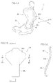
- the seat 10 is a vehicle seat, and comprises a seat cushion 20, a seatback 30, and a strut 40.
- the seatback 30 is secured to the strut 40 and isolated from the seat cushion.
- the upper half 30U and lower half 30L of the seatback 30 are shaped, greatly different in widths.
- the lower half 30L is narrower than the upper half 30U, and shaped like an elongate rectangle. That is, the upper half 30U of the seatback 30 has a part shaped like a trapezoid and extending from either side, and is therefor, broader than the lower half 30L in the left-right direction of the seat 10.
- the lower half 30L is narrower than the upper half 30U because it has not trapezoidal parts.
- the lower half 30L is designed to support, in the main, that part of the occupant, which lies between the hips and lower ribs.
- the upper half 30U supports, in the main, the shoulder blades of the occupant.
- the surface of the seatback 130 of the conventional seat does not extend up to the level where it may cover and support the occupant's shoulder blades from back. Further, the seat surface of the seatback 130 is shaped flat in the left-right direction of the seat, and does not wrap or support the occupant's left or right shoulder blade at the parts of the shoulder blade.
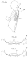
- the seat surface of the seatback 30 curves, bulging in the up-down direction, gradually upward along the occupant's shoulder blades, and recedes in the left-right direction, supporting the occupant's shoulder blades.
- the seat surface of the seatback 30 extends to support the lower part of the occupant's neck in the up-down direction, thus supporting the same, and recedes at the parts 36' of the shoulder blade in the left-right direction.
- the seat surface of the seatback 30 gently recedes at the part 37' of the occupant's ribs, extending in the left-right direction.
- the seat surface of the seatback 30 much recedes at two parts 36' to support the occupant's left and right shoulder blades, and less bulges at the part lying between the two parts 36'.
- the seat surface of the seatback 30 extends upward, first gently inclined backward and then gently inclined forward shortly before the top part.
- the seat surface of the seatback 30 extends up, also along the occupant's shoulder blades 36, to the level where it may cover the shoulder blades from back.
- the seat surface of the seatback 30 is shaped, extending along the occupant's left and right shoulder blades 36 and also along the occupant's ribs 37, in the left-right direction, too.
- the seat surface of the seatback 30 is curved in the up-down direction and left-right direction, along the occupant's shoulder blades 36 and ribs 37.
- the seat surface of the seatback 30 curves in the up-down direction, gradually bulging along the occupant's shoulder blades, and recedes in the left-right direction, supporting the occupant's ribs 37. Further, in the up-down direction, the seat surface of the seatback 30 curves along the occupant's shoulder blades and extends to the level where it may cover the shoulder blades from back. In the left-right direction, the seat surface of the seatback 30 recedes at the occupant's left and right shoulder blades. Therefore, the occupant's shoulder blades 36 and ribs 37 can be supported on the seat surface of the seatback 30.
- the seat surface of the seatback can contact the occupant's back (i.e., shoulder blades and ribs) at a large area between the back of the occupant and the seat surface of the seatback, and the contact pressure is low.
- Only the seat surface of the seatback 30 has a special shape, and the internal structure of the seatback need not be complex in structure. Since the total length at the parts of the occupant's ribs and shoulder blades (i.e., trunk width) differs but a little, the occupant can feel well fit in the seat, regardless of his or her physique (i.e., trunk width) as he or she is supported, mainly at the ribs and shoulder blades.
- the side supports may not be provided at the left and right edges of the seatback 30, respectively. If this is the case, the seat 10 is simplified in structure. Without side supports, the seat surface of the seatback 30 is simplified in shape, which enhances the outer appearance of the seat 10.
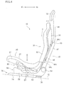
- the seat cushion unit 22 has a U-notch 22a in the middle part of the rear end.
- the rear end of the seat cushion unit 22 is shaped like letter U as seen from above, and has the left and right ends bulging upward from the bottom of the U-notch 22a.
- the U-notch 22a has a width in the left-right direction of the seat 10 and a length in the front-back direction of the seat which the lower half 30L of the seatback is loosely fitted.
- HP indicates the hip point of the occupant.
- the lower half 30L of the seatback is narrower than the upper half 30U of the seatback, and the U-notch 20a loosely holding the lower half 30L is cut in the middle part of the rear end of the seat cushion 20.
- No gap is provided between the rear end of the seat cushion and the lower end of the seatback even if the seat cushion and the seatback is lifted or lowered, relative to each other. Therefore, the seat cushion 20 and the seatback 30 can be lifted or lowered, relative to each other, in order to adjust the position of the seatback in accordance with the occupant's physique (i.e., height).
- the seat cushion 20 and the seatback 30 may be configured to move up and down relative to each other.
- the seatback 30 (more precisely, the seat surface thereof) can be set to an optimal position for supporting the occupant at the ribs and shoulder blades, enabling the occupant to feel well fit in the seat, regardless of his or her physique (i.e., height).
- the lower half 30L of the seatback 30 is thus made narrower than the upper half 30U, and the U-notch 20a for loosely holding the lower half 30L is made in the middle part of the rear end.
- This minor change in shape can adjust the position of the seatback (i.e., position of seat surface) in accordance with the occupant's physique (i.e., height).
- the lower half 30L of the seatback 30 is loosely fitted in the U-notch 20a made in the middle part of the rear end of the seat cushion unit 22. Further, the left and right end parts 20b, defining the U-notch 20a, do not interfere with the seatback.
- the left and right end parts 20b can therefore have any shape desirable, without preventing the seat cushion 20 and the seatback 30 from moving up or down, relative to each other.
- the left and right end parts 20b extend upward. If they extend to a level higher than the U-notch 20a, the seat cushion 20 will may rap the occupant's buttocks from the sides. This prevents the occupant's buttocks from moving in the left-right direction of the seat 10. As a result, the occupant will feel his buttocks well fitted in the seat 10.
- either the seat cushion or the seatback may be lifted or lowered, or both the seat cushion and the seatback may be lifted or lowered independently of each other.
- the seat cushion 20 may be lifted and lowered by, for example, a seat lifter.
- the strut may be composed of a fixed pole and a movable pole that can move up and down with respect to the fixed pole. If secured to the movable pole, the seatback can move up and down.
- the seat 10 may be configured to lift and lower either the seat cushion or the seatback. Alternatively, both the seat cushion and the seatback may be lifted and lowered.
- Fr and Rr indicate the forward and backward directions with respect to the driver seated in the driver seat
- L and R indicate the leftward and rightward directions with respect to the driver.
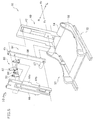
- the seat 10 is a vehicle seat, and comprises a seat cushion 20, a seatback 30, a strut 40, a riser 50 serving as base, a lifting/lowering means 60, and a seat sliding mechanism 70.
- the seat cushion 20 comprises a seat cushion unit 22 composed of a pad and a trim cover covering the pad, and a cushion panel 24 holding the seat cushion unit 22.
- the seatback 30 comprises a seatback unit 32 composed of a pad and a trim cover covering the pad, and a back panel 34 holding the seatback unit 32.
- the cushion panel 24 and the back panel 34 are made of, for example, fiber-reinforced plastic (FRP).
- FRP fiber-reinforced plastic
- the seat cushion unit 22 is adhered to the upper surface of the cushion panel 24.
- the seatback unit 32 is adhered to the front surface of the back panel 34.
- the seat cushion unit 22 is indicated by a one-dot, dashed line, specifying the shape of the cushion panel 24.
- the seat sliding mechanism 70 is of the type known to the public.
- the seat sliding mechanism 70 includes fixed rails 74 secured to the vehicle floor 72 and movable rails 76 inserted in the fixed rails 74, respectively, to slide back and forth.
- the riser 50 is secured, and is used as seat base.
- the riser 50 has left and right side frames 52, a front coupling member coupling the front ends of the left and right side frames, and a rear coupling member coupling the rear ends of the left and right side frames 52.
- the rear coupling member is a hollow rod 54.
- the lifting/lowering means 60 includes a seat lifter 61 arranged between the seat cushion 20 and the riser 50.
- the seat lifter 61 is of a known type such as X link type. More precisely, the seat lifter 61 comprises a pair of links 62 fastened with a pin, forming an X-shaped member. The links 62 are secured, at upper end with a pin to an upper bar 63, and at lower end with a pin to a lower bar (not shown). Of these two pins, the front-side pin can slide back and forth.
- the upper bar 63 is secured to the lower surface of the cushion panel 24, and the lower bar is provided inside the side frames 52 of the riser 50. So configured and provided between the seat cushion 20 and the riser 50, the seat lifter 61 can lift and lower the seat cushion 20.
- the strut 40 has its lower end mounted on, or welded to, the rear coupling member, i.e., hollow rod 54 that couples the rear ends of the left and right side frames of the riser 50.
- the strut 40 is secure to the hollow rod 54, extending substantially upright (more precisely, incline rearward a little).
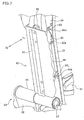
- the strut 40 includes a main unit 42 and a movable pole 44.
- the main unit 42 is welded, at lower end, to the riser 50.
- the movable pole 44 is incorporated in the main unit 42, able to slide up and down.
- a pair of brackets 34U and another pair of brackets 34L are provided at the back of the back panel 34.
- the brackets 34U are vertically spaced from the brackets 34L.
- the brackets of either pair are spaced sidewise by the width of the movable pole 44.
- the brackets 34U and the brackets 34L secure the back panel 34 to the movable pole 44, and the seatback 30 can therefore slide up and down, together with the movable pole.
- a strut 46 is secured to the back of the back panel 34.
- a headrest 18 is secured to the top of the strut 46. The headrest 18 can therefore be moved up and down together with the seatback 30, as the movable pole 44 is moved up and down.
- the strut 46 is secured to the back of the back panel 34, and needs only to move up and down together with the seatback 30. It may be secured to the back of the back panel 34, by an appropriate method available.
- the lower brackets 34L are provided at a lower part of the back panel 34, and the upper brackets 34U are provided at a little above the middle section of the back panel 34.
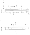
- the seat lifter 61 lifts or lowers the seat cushion 20 with respect to the seatback 30, and a lifting/lowering mechanism other than the seat lifter 61 lifts or lowers the seatback with respect to the seat cushion. That is, the lifting/lowering means 60 includes a lifting/lowering mechanism (seatback lifting/lowering mechanism) 64, in addition to the seat lifter 61.
- the seatback lifting/lowering mechanism 64 is based on the seat sliding mechanism known to the public.
- the mechanism 64 includes a fixed rail 65 and a movable rail 66 covering the fixed rail 65.
- the mechanism 64 is identical in configuration to the known seat sliding mechanism, except that the fixed rail 65 is provided inside the movable rail 66. Instead, the movable rail 66 may, of course, be provided inside the fixed rail 65.
- the seat siding mechanism of the known type is configured to slide back and forth.
- the seatback lifting/lowering mechanism 64 is configured to slide in vertical direction (thus able to move up and down).
- the seatback lifting/lowering mechanism 64 is similar to the known seat sliding mechanism in basic configuration, and will not described in detail.
- a motor 67 is mounted on the fixed rail 65, though not described here in detail.
- the driving force of the motor 67 is reduced and rotates a pinion gear (not shown) meshed with the lack (not shown) provided on the movable rail 66.
- the motor 67 is driven, the movable rail 66 will move up or down along the fixed rail 65, while being guided by the fixed rail 65.
- the rear coupling member 54 coupling the rear ends of the left and right side frames 52 of the riser is a hollow rod.
- the motor 67 of the seatback lifting/lowering mechanism 64 is incorporated in the hollow rod. The motor 67 is therefore concealed, not impairing the outer appearance of the seatback lifting/lowering mechanism 64.
- the main unit 42 of the strut 40 is fastened to the fixed rail 65 and the movable pole 44 is fastened to the movable rail 66, for example by using bolts, respectively.
- the main unit 42 and the movable pole 44 have a U-shaped cross section, respectively.
- the main unit 42 opens at front, and its front is covered with the movable pole 44.
- the seatback lifting/lowering mechanism 64 is arranged between the main unit 42 and the movable pole 44.
- the seatback lifting/lowering mechanism 64 can be small and light, and can yet easily move the movable pole 44 with respect to the main unit 42 of the strut 40. Secured to the movable pole 44, the seatback 30 is lifted or lowered, together with the movable pole. The seatback 30 can therefore be adjusted in the position of the seat surface, in accordance with the occupant's physique. This makes the occupant feel well fit in the seat.
- the lower half 30L of the seatback is made narrower than the upper half 30U.
- the U-notch 20a is made in the middle part of the rear end of the seat cushion, and loosely holds the narrow lower half of the seatback. Therefore, no gap will be made between the rear end of the seat cushion and the lower end of the seatback even if the seatback 30 is lifted or lowered and thereby the seatback can be adjusted in position in accordance with the occupant's physique.
- the lower half 30L of the seatback 30, which is narrower than the upper half 30U, is loosely fitted in the U-notch 20a that is made in the middle part of the rear end of the seat cushion.
- the left and right end parts 20b, defining the U-notch 20a between them, does not interfere with the seatback 30, and the seatback 30 can be lifted and lowered without interfering with the seat cushion 20.
- the seatback 30 can be adjusted in position in accordance with the occupant's physique, not impairing the occupant's feeling of being well fit in the seat 10, even when the seat lifter 61 lifts or lowers the seat cushion 20. Even after the seat cushion 20 has been lifted or lowered, no gap is made between the rear end of the seat cushion and the lower end of the seatback. Further, the seat cushion can be lifted and lowered, never interfering with the seatback 30.
- two pins 44b protrude from the left and right walls 44a of the movable pole.
- the pins 44b are pivotally held, respectively in two support holes made in the left and right lower brackets 34L provided on the lower part of the back of the back panel 34.
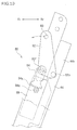
- the seat 10 further comprises an inclination mechanism 80 for the seatback configured to incline the seatback 30.
- the inclination mechanism 80 is provided on the movable pole 44, at a position well above the pins 44b protruding from the walls of the movable pole.
- the inclination mechanism (or seatback inclining mechanism) 80 includes a main link 82, a drive link 84, and a regulation link 86.
- the main link 82 is composed of a pair of main links (or first and second main links) 82-1 and 82-2.
- Each of the first and second main links 82-1 and 82-2 has one support hole 82a in one end (upper end), and two support holes 82b and 82c in the other end (lower end, or free end).
- the firs main link 82-1 has another support hole 82d made in a corner of the lower end (free end) of the first main link 82-1.
- a connecting rod 82e has its ends fitted, respectively in the support holes 82b made in the lower ends of the first and second main links 82-1 and 82-2.
- the first main link 82-1 and the second main link 82-2 are thereby coupled and can be moved together.
- Pins 83 pass through the support holes 82a and are pivotally supported, by the left and right brackets 34U provided at the upper part of the back of the back panel 34 (see FIG. 7 ).
- a pin (rotation control pin) 82f is fitted in the support hole 82d made in a lower corner of the first main link 82-1.
- the drive link 84 and the regulation link 86 are arranged outside the first main link 82-1.
- a support hole 84c is made in the upper end of the drive link 84, and a support hole 86c is made in the upper end of the regulation link 86.
- Step pins extend outwards from the left and right walls 44a of the movable pole, passing through the support holes 84c and 86c and a washer 88, and then through the support hole 82c of the first main link 82-1, and is pivotally supported by the side walls 44a of the movable pole.
- a step bolt (not shown) extends from outside, passing through another washer 88 and the support hole 82c of the second main link 82-2, and is secured to the side walls 44a of the movable pole 44.
- the main link 82 is thereby arranged between the left and right side walls of the movable pole 44.
- Holes 84f and 86f in which the rotation control pin 82f extending from the first main link 82-1 is inserted, are made in the drive link 84 and the regulation link 86, respectively.
- a section gear 84g is provided at the lower end of the drive link 84.
- the hole 86f of the regulation link 86 is an elongated hole arching around the support hole 86c made in the upper end of the regulation link.
- the step pin extends through the support hole of the support hole 82c of the first main link 82-1, the support hole 84c of the drive link 84 and the support hole 86c of the regulation link 86. Further, the rotation control pin 82f extends from the first main link 82-1 and is inserted in the hole 84f of the drive link. The drive link 84 and the main link 82 can therefore rotate together.
- Two holes 86h are made in the lower end of the regulation link 86. Using these holes 86h, the regulation link is bolted to the movable pole 44.
- an actuator 89 incorporating a motor (not shown) is secured to the movable pole 44.
- the section gear 84g of the drive link extends into the actuator 89 and is set in screw engagement with a pinion gear 89g.
- the drive link 84 which has the section gear 84g set in mesh with the pinion gear, rotates when the pinion gear 89g is rotated by the motor. As a result, the main link 82 rotates together with the drive link.
- the back panel 34 can therefore incline forward and backward (or rotate) around the pins 44b pivotally, as much as allowed by the rotation control pin 82f and the elongated hole 86f.
- a torque limiter (not shown) is provided on the actuator 89 and arranged between the motor and the pinion gear 89g, and therefore controls the output of the motor.
- the main link 82 and the drive link 84, which rotate together, may be formed integral.
- the drive link 84 may not be used, and the first main link 82-1 may extend downward from the rotation control pin 82f, and the section gear 84g may be provided on the lower edge of the first main link 82-1. Further, the rotation control pin 82f may be inserted directly into the elongated hole 86f. In this case, the back panel 34 can rotate forward and backward around the pins 44b pivotally, as much as allowed by the rotation control pin and the elongated hole.
- the inclination mechanism 80 can be simplified in structure because the drive link 84 is not at all.
- the lower brackets 34L are provided on the lower end of the back panel 34, and the seatback 30 is inclined (or rotated) around the pins 44b pivotally supported by the lower brackets 34L. That is, the center of rotation is set at the lower end of the seatback 30. This suppresses the back-and-forth motion of the lower half 30L of the seatback, which supports that part of the occupant, lying between the hips and lower ribs, even if the seatback 30 is inclined. The inclination of the seatback can therefore be adjusted without increasing the interference between the U-notch 20a made in the rear end of the seat cushion and the lower end of the seat back 30.
- the torque limiter controls the output of the motor, which is transmitted to the pinion gear 89g. If another vehicle hits the rear of the vehicle having the seat 10, imposing an impact on the seat 10. In this case the pinion gear 89g slips, inclining the seatback 30 while absorbing the impact energy. This moderates the impact applied to the occupant, ensuring the safety of the occupant.
- the back panel 34 is lifted or lowered, together with the movable pole 44, along the main unit (fixed pole) 42, in accordance with the occupant's physique(height), without impairing the occupant's feeling of being well fit in the seat 10. Hence, not only can the seatback 30 be adjusted in position, but also can the back panel 34 incline to the movable pole.
- the seatback 30 If the seatback 30 is inclined at the position to which it has been lifted or lowered, the seatback can be further adjusted in position in accordance with the occupant's physique (height), without impairing the occupant's feeling of being well fit at the seat surface of the seatback.
- the lifting/lowering means 60 configured to lift and lower the seat cushion 20 and the seatback 30, relative to each other, includes the seat lifter 61 for the seat cushion in addition to the seatback lifting/lowering mechanism 64. Further, the seat cushion 20 and the seatback 30 are configured to be lifted and lowered, independently of each other. Hence, the seat cushion 20 and the seatback 30 can be lifted and lowered relative to each other, for a longer distance. This reliably adjusts the seatback in position in accordance with the occupant's physique (height). Both an occupant much bigger than average persons and an occupant much smaller than average persons can feel well fit in the seat 10.
- the seat cushion 20 will move back and forth. Nonetheless, the inclination mechanism 80 for the seatback 30 can adjust the inclination of the seatback. This gives the occupant a line of sight appropriate for his or her physique. The occupant can therefore feel fit in the seat 10, regardless of his or her physique, even while the seat lifter 61 is operating.
- the inclination mechanism 80 for the seatback may be provided directly on the main unit 42, not on the movable pole 44, and the seatback 30 may be provided on the main unit 42 and may be inclined. In this case, the seatback will be adjusted in position in accordance with the occupant's physique (height) if the seat lifter 61 lifts or lowers the seat cushion 20.
- the seatback 30 of this invention is a single-piece product, never to have a gap even if it is lifted or lowered. This ensures the occupant a well-fit feeling on the seat surface of the seatback.
- the strut 46 which has the headrest 18 on the top and is secured to the movable pole 44, is lifted or lowered together with the seatback 30, whereby the headrest is lifted or lowered.
- the headrest 18 can therefore support the occupant's head, not impairing the occupant's feeling of being well fit in the seat 10, even if the seat surface of the seatback 30 is adjusted in position in accordance with the occupant's physique.
- the seat according to this invention can support the occupant, mainly at the ribs and shoulder blades, making the occupant feel well fit in the seat, regardless of his or her physique (i.e., trunk width).
- the lower half of the seatback may be formed narrower than the upper half, and the seat cushion may have a U-notch made in the middle part of the rear end thereof.
- the seatback can be adjusted in position (i.e., position of its surface) in accordance with the occupant's physique (i.e., height), if the seat cushion and the seatback are lifted and lowered relative to each other.
- the embodiment described above is a vehicle seat, as in most cases.
- the present invention can be modified as any seats that have a seat cushion and a seatback, and is not limited to a vehicle seat.
- One example of the lifting/lowering means of the seat cushion and the seatback and the seat sliding mechanism 70 can be disclosed as below.
Landscapes
- Engineering & Computer Science (AREA)
- Aviation & Aerospace Engineering (AREA)
- Transportation (AREA)
- Mechanical Engineering (AREA)
- Seats For Vehicles (AREA)
Applications Claiming Priority (1)
| Application Number | Priority Date | Filing Date | Title |
|---|---|---|---|
| JP2013237968A JP6202734B2 (ja) | 2013-11-18 | 2013-11-18 | シート |
Publications (2)
| Publication Number | Publication Date |
|---|---|
| EP2873556A1 EP2873556A1 (en) | 2015-05-20 |
| EP2873556B1 true EP2873556B1 (en) | 2016-08-31 |
Family
ID=51900249
Family Applications (1)
| Application Number | Title | Priority Date | Filing Date |
|---|---|---|---|
| EP14193102.2A Not-in-force EP2873556B1 (en) | 2013-11-18 | 2014-11-13 | Seat |
Country Status (3)
| Country | Link |
|---|---|
| US (1) | US9381840B2 (enExample) |
| EP (1) | EP2873556B1 (enExample) |
| JP (1) | JP6202734B2 (enExample) |
Families Citing this family (29)
| Publication number | Priority date | Publication date | Assignee | Title |
|---|---|---|---|---|
| WO2012043807A1 (ja) * | 2010-10-01 | 2012-04-05 | 日産自動車株式会社 | 車両用シートおよび車両用シートの剛性設定方法 |
| JP6192221B2 (ja) * | 2013-11-18 | 2017-09-06 | 株式会社タチエス | シート |
| US10328823B2 (en) | 2014-06-09 | 2019-06-25 | Lear Corporation | Adjustable seat assembly |
| US9987961B2 (en) | 2014-06-09 | 2018-06-05 | Lear Corporation | Adjustable seat assembly |
| US9981577B2 (en) | 2015-01-19 | 2018-05-29 | Lear Corporation | Thoracic air bladder assembly |
| US9884570B2 (en) | 2015-05-19 | 2018-02-06 | Lear Corporation | Adjustable seat assembly |
| US9845026B2 (en) | 2015-05-19 | 2017-12-19 | Lear Corporation | Adjustable seat assembly |
| US9661928B2 (en) | 2015-09-29 | 2017-05-30 | Lear Corporation | Air bladder assembly for seat bottoms of seat assemblies |
| JP6621173B2 (ja) * | 2015-10-01 | 2019-12-18 | 株式会社タチエス | シート及び車両用シート |
| JP6595295B2 (ja) * | 2015-10-14 | 2019-10-23 | 株式会社タチエス | 車両用シート |
| US9827888B2 (en) | 2016-01-04 | 2017-11-28 | Lear Corporation | Seat assemblies with adjustable side bolster actuators |
| US9957010B2 (en) * | 2016-03-08 | 2018-05-01 | High End Seating Solutions, Llc | Seat back support assembly for adjustably supporting a seat back of a vehicle |
| US9889773B2 (en) * | 2016-04-04 | 2018-02-13 | Ford Global Technologies, Llc | Anthropomorphic upper seatback |
| US20170291524A1 (en) * | 2016-04-11 | 2017-10-12 | Lear Corporation | Comfort system for seating backs with reduction in pur volume and environmentally friendly construction |
| US10563770B2 (en) * | 2016-05-05 | 2020-02-18 | National Oilwell Varco, L.P. | Washpipe assemblies for a power swivel |
| DE102016215048B4 (de) * | 2016-08-12 | 2023-10-12 | Lear Corp. | Sitzanordnung und Verfahren zum Montieren einer Sitzanordnung |
| JP6512196B2 (ja) * | 2016-09-15 | 2019-05-15 | トヨタ自動車株式会社 | 車両用シート |
| US10384566B2 (en) * | 2017-08-25 | 2019-08-20 | Ford Global Technologies, Llc | Vehicle seat assembly |
| US10207776B1 (en) | 2017-09-01 | 2019-02-19 | Brunswick Corporation | Seat and seat assembly for use in a boat |
| US10549658B2 (en) * | 2018-04-26 | 2020-02-04 | Rivian Ip Holdings, Llc | Automotive vehicle seat with indented lower side portions |
| USD887154S1 (en) * | 2018-06-13 | 2020-06-16 | Tachi-S Co., Ltd. | Vehicle seat |
| KR101935205B1 (ko) * | 2018-06-29 | 2019-01-08 | 손익수 | 차량 시트 등받이에 설치되는 위치 조절이 가능한 경추 지지장치 |
| CN111376805A (zh) * | 2018-12-29 | 2020-07-07 | Sabic环球技术有限责任公司 | 用于电动车辆的塑料座椅框架 |
| US11603019B2 (en) * | 2019-06-17 | 2023-03-14 | Zoox, Inc. | Seat crush structure |
| US11007908B2 (en) | 2019-06-25 | 2021-05-18 | Ford Global Technologies, Llc | Upper thoracic support paddle attachment assembly |
| USD953758S1 (en) * | 2019-06-27 | 2022-06-07 | Bentley Motors Limited | Seat |
| JP2024036771A (ja) * | 2022-09-06 | 2024-03-18 | ダイハツ工業株式会社 | 車両用シート |
| EP4454940A1 (fr) * | 2023-04-25 | 2024-10-30 | Renault s.a.s | Siege a dossier basculant |
| FR3148178A1 (fr) * | 2023-04-25 | 2024-11-01 | Renault S.A.S. | Siège pivotant |
Family Cites Families (77)
| Publication number | Priority date | Publication date | Assignee | Title |
|---|---|---|---|---|
| US3133765A (en) * | 1962-08-30 | 1964-05-19 | Ion Corp | Chair |
| GB1257927A (enExample) * | 1968-11-27 | 1971-12-22 | ||
| DE2064419C3 (de) * | 1970-12-30 | 1979-08-30 | Recaro Gmbh & Co, 7000 Stuttgart | Rückenlehne für Kraftfahrzeugsitze |
| JPS59140927U (ja) * | 1983-03-11 | 1984-09-20 | 株式会社タチエス | シ−トクツシヨン昇降式車輌用座席 |
| DE3440985A1 (de) * | 1984-11-09 | 1986-05-15 | German 8700 Würzburg Gresser | Orthopaedisch optimierter fahrzeugsitz |
| DE3511216C1 (de) * | 1985-03-28 | 1986-05-15 | Keiper Recaro GmbH & Co, 5630 Remscheid | Fahrzeugsitz |
| JPH0534430Y2 (enExample) | 1988-03-23 | 1993-08-31 | ||
| DE3821554A1 (de) * | 1988-06-22 | 1989-12-28 | Isringhausen Geb | Fahrzeugsitz mit einem rueckenlehnenrahmen |
| US4902070A (en) * | 1988-09-16 | 1990-02-20 | Child Riding Incorporated | Foldable automobile convertible seat |
| JPH057957Y2 (enExample) * | 1988-11-09 | 1993-03-01 | ||
| JPH0646364Y2 (ja) * | 1989-05-23 | 1994-11-30 | 池田物産株式会社 | シートバックフレーム |
| IT1232129B (it) * | 1989-07-05 | 1992-01-23 | Fiat Auto Spa | Schienale di sedile a struttura stratificata |
| US5018788A (en) * | 1989-12-08 | 1991-05-28 | Tempress Incorporated | Foldable seat |
| US5011225A (en) * | 1990-03-16 | 1991-04-30 | Tachi-S Co. Ltd. | Structure of a movable headrest |
| US5114209A (en) * | 1990-03-21 | 1992-05-19 | Dunn John C | Chair insert having a contoured back support portion and a seat support portion |
| US6015189A (en) * | 1991-11-05 | 2000-01-18 | Genus Medical Inc. | Adjustable chair |
| CA2057712C (en) * | 1991-12-16 | 1998-10-06 | William Ross Breen | Back support and internal frame |
| JPH07308233A (ja) * | 1994-05-18 | 1995-11-28 | Eiichiro Tanaka | シートバックの形状 |
| US5549357A (en) * | 1994-12-12 | 1996-08-27 | Quickie Designs Inc. | Adjustable backrest apparatus for wheelchairs |
| DE19643977C2 (de) * | 1996-10-31 | 2000-03-30 | Keiper Gmbh & Co | Fahrzeugsitz mit Multifunktionslehne |
| US5769498A (en) * | 1997-02-12 | 1998-06-23 | Lear Corporation | Detachable vehicle seat bolster |
| DE19845011B4 (de) * | 1998-09-30 | 2011-07-07 | Volkswagen AG, 38440 | Seitenverkleidung für einen höhenverstellbaren Fahrzeugsitz |
| DE19853156B4 (de) * | 1998-11-18 | 2006-04-13 | Girsberger Holding Ag | Sitz |
| US6139109A (en) * | 1999-02-08 | 2000-10-31 | The Joie Of Seating, Inc. | Race car seat and jig and method for making the same |
| US6425635B1 (en) * | 1999-11-01 | 2002-07-30 | Invacare Corporation | Weight-shifting reclining and tilting wheelchair seat |
| US6390554B1 (en) * | 1999-11-23 | 2002-05-21 | 1239907 Ontario Limited | Weight positioning reclining seat kit for wheelchairs |
| US6409265B1 (en) * | 2000-05-31 | 2002-06-25 | Sunrise Medical Hhg, Inc. | Tilting and reclining wheelchair |
| FR2810279B1 (fr) * | 2000-06-16 | 2002-10-11 | Faure Bertrand Equipements Sa | Siege de vehicule comportant un dossier pivotant rappele vers l'avant par une barre de torsion |
| US6550858B1 (en) * | 2000-09-21 | 2003-04-22 | Lear Corporation | Extricable seat assembly |
| US6450581B1 (en) * | 2000-09-29 | 2002-09-17 | Sunrise Medical Hhg Inc. | Power legrest for a wheelchair |
| JP3623441B2 (ja) * | 2000-10-30 | 2005-02-23 | ジョンソン コントロールズ オートモーティブ システムズ株式会社 | 自動車用シートバック |
| US6530622B1 (en) * | 2001-03-16 | 2003-03-11 | Johnson Controls Technology Company | Biomechanical vehicle seat |
| DE60306496T2 (de) * | 2002-02-12 | 2007-07-05 | Johnson Controls Technology Company, Holland | Automobilsitz mit aktiver Rückenlehne |
| US6817673B2 (en) * | 2002-04-17 | 2004-11-16 | Lear Corporation | Vehicle seat assembly |
| US6969114B2 (en) * | 2002-06-07 | 2005-11-29 | Ed Keilhauer | Total spinal support |
| FR2849812B1 (fr) * | 2003-01-14 | 2006-02-17 | Faurecia Sieges Automobile | Siege de vehicule protegeant un utilisateur contre les effets d'un choc arriere |
| DE20302994U1 (de) * | 2003-02-25 | 2003-06-05 | Stanzwerk Wetter Sichelschmidt GmbH & Co. KG, 58300 Wetter | Sitzmöbel mit Rückenlehne und Kopfstütze |
| US6752464B1 (en) * | 2003-02-26 | 2004-06-22 | Shin Yeh Enterprise Co., Ltd. | Modular furniture frame |
| DE10327639A1 (de) * | 2003-06-20 | 2005-01-13 | Recaro Gmbh & Co.Kg | Sportsitz für ein Fahrzeug, insbesondere für ein Kraftfahrzeug |
| US7296856B2 (en) * | 2003-10-08 | 2007-11-20 | Pride Mobility Products Corporation | Reclining seat with movable back support |
| EP1524147B1 (de) * | 2003-10-16 | 2010-03-17 | Lazzerini S.r.l. | Sitz zur Beförderung von Personen |
| US7040708B2 (en) * | 2003-11-05 | 2006-05-09 | Racetech Manufacturing Ltd. | Vehicle seat |
| EP1689614B1 (en) * | 2003-11-11 | 2010-07-28 | Johnson Controls Technology Company | Seat back adjustment mechanism |
| US6945601B1 (en) * | 2003-12-23 | 2005-09-20 | Yao-Chuan Wu | Multi-stage backrest assembly |
| US7021710B2 (en) * | 2004-03-10 | 2006-04-04 | Cosco Management, Inc. | Juvenile vehicle seat with movable headrest |
| DE102004045573B4 (de) * | 2004-09-17 | 2007-11-15 | Grammer Ag | Sitz mit einer Ergomechanik |
| US7331633B2 (en) * | 2004-11-29 | 2008-02-19 | Cosco Management, Inc. | Juvenile vehicle seat with quick-connect backrest |
| US7547068B2 (en) * | 2005-02-24 | 2009-06-16 | Davis Bradley J | Adjustable seat for automobiles and trucks |
| DE102005017634B4 (de) * | 2005-04-15 | 2008-04-17 | Grammer Ag | Fahrzeugsitz mit verformbarer S-förmiger Rückenlehne |
| DE102005021482A1 (de) * | 2005-05-10 | 2006-11-16 | Johnson Controls Gmbh | Fahrzeugsitz |
| JP4447515B2 (ja) * | 2005-06-08 | 2010-04-07 | トヨタ紡織株式会社 | 車両用シートの操作レバー配置構造 |
| DE102006002069B4 (de) * | 2006-01-13 | 2016-07-28 | Johnson Controls Gmbh | Fahrzeugsitz, insbesondere Kraftfahrzeugsitz, mit einer Lehnen-bzw. einer Lehnen- und einer Höhenverstellung und einer Crashverlagerung der Rückenlehnenstruktur |
| US7896438B2 (en) * | 2006-09-29 | 2011-03-01 | Sunrise Medical Hhg, Inc. | Shapeable wheelchair seatback assembly |
| JP5087975B2 (ja) * | 2007-04-06 | 2012-12-05 | トヨタ紡織株式会社 | 車両用シート |
| DE102007062635B4 (de) * | 2007-12-20 | 2011-02-10 | Keiper Gmbh & Co. Kg | Fahrzeugsitz, insbesondere Kraftfahrzeugsitz |
| US7488026B1 (en) * | 2007-12-28 | 2009-02-10 | Nissan Technical Center North America, Inc. | Guard member for adjustable seat in a vehicle |
| DE102008012715B3 (de) * | 2008-03-03 | 2009-07-16 | Keiper Gmbh & Co. Kg | Fahrzeugsitz, insbesondere Kraftfahrzeugsitz |
| US7931337B2 (en) * | 2008-03-20 | 2011-04-26 | Gm Global Technology Operations, Llc | Recliner release actuation through active materials |
| JP5476907B2 (ja) * | 2009-10-07 | 2014-04-23 | トヨタ紡織株式会社 | 車両用シートバック |
| JP5297330B2 (ja) | 2009-10-16 | 2013-09-25 | 本田技研工業株式会社 | シート |
| DE102009052709A1 (de) * | 2009-11-11 | 2011-05-12 | GM Global Technology Operations LLC, Detroit | Kraftfahrzeug mit Verstelleinrichtung mit Hebeleinrichtung |
| ES2663636T3 (es) * | 2009-11-23 | 2018-04-16 | Faurecia Automotive Seating, Llc | Cubierta de comodidad controlable para asiento de vehículo |
| TWM378690U (en) * | 2009-12-01 | 2010-04-21 | Chi Bo Industry Co Ltd | Machine capable of adjusting gap between seat pad and back cushion |
| JP5513213B2 (ja) * | 2010-03-30 | 2014-06-04 | 日本発條株式会社 | 車両用シートバック及びこれを備えた車両用シート |
| JP5513212B2 (ja) * | 2010-03-30 | 2014-06-04 | 日本発條株式会社 | 車両用シートバック及びこれを備えた車両用シート |
| US9073575B2 (en) * | 2010-05-12 | 2015-07-07 | GM Global Technology Operations LLC | Memory features for a manually adjustable apparatus |
| EP2428393B1 (en) * | 2010-09-10 | 2019-11-13 | Faurecia Automotive Seating, Inc. | Easy-entry seat-back release system for vehicle seat |
| US8646795B2 (en) * | 2010-11-10 | 2014-02-11 | Invacare Corporation | Reclining seat |
| JP3169443U (ja) * | 2011-05-20 | 2011-07-28 | 泰樺家具股▲ふん▼有限公司 | 高さ調節椅子 |
| WO2013040085A2 (en) * | 2011-09-12 | 2013-03-21 | Faurecia Automotive Seating, Inc. | Controllable comfort shell for vehicle seat |
| EP2760702B1 (en) * | 2011-09-26 | 2018-09-05 | Faurecia Automotive Seating, LLC | Vehicle seat backrest with flexural joint motion-control |
| JP5848088B2 (ja) * | 2011-10-11 | 2016-01-27 | 日本発條株式会社 | 車両用シート |
| US8979203B1 (en) * | 2012-04-24 | 2015-03-17 | Gill Industries, Inc. | Head restraint assembly |
| FR2991667B1 (fr) * | 2012-06-06 | 2015-05-29 | Eads Sogerma | Siege d'aeronef a structure monopoutre et aeronef comportant un tel siege |
| US9061616B2 (en) * | 2013-01-24 | 2015-06-23 | Ford Global Technologies, Llc | Articulating headrest assembly |
| US9669744B2 (en) * | 2013-02-18 | 2017-06-06 | Faurecia Automotive Seating, Llc | Seat back for vehicle seat |
| TWI516246B (zh) * | 2013-09-18 | 2016-01-11 | 何浩明 | 可攜式且具脊椎矯正功能之背架結構 |
-
2013
- 2013-11-18 JP JP2013237968A patent/JP6202734B2/ja active Active
-
2014
- 2014-11-13 EP EP14193102.2A patent/EP2873556B1/en not_active Not-in-force
- 2014-11-18 US US14/546,686 patent/US9381840B2/en not_active Expired - Fee Related
Also Published As
| Publication number | Publication date |
|---|---|
| US9381840B2 (en) | 2016-07-05 |
| US20150165949A1 (en) | 2015-06-18 |
| JP2015098213A (ja) | 2015-05-28 |
| JP6202734B2 (ja) | 2017-09-27 |
| EP2873556A1 (en) | 2015-05-20 |
Similar Documents
| Publication | Publication Date | Title |
|---|---|---|
| EP2873556B1 (en) | Seat | |
| EP2873555B1 (en) | Vehicle seat | |
| US11338714B2 (en) | Vehicle seat with cantilevered headrest assembly and positioning system | |
| CN106965727B (zh) | 拟人化的可枢转的上部座椅靠背支撑件 | |
| CN108528293B (zh) | 用于仰卧式机动车辆座椅总成的机构 | |
| US10065535B1 (en) | Seatback lift mechanism for a supine motor vehicle seating assembly | |
| KR102726813B1 (ko) | 자동차용 릴렉션 컴포트 시트 | |
| WO2009002743A1 (en) | Seat headrest | |
| KR102153216B1 (ko) | 자동차용 멀티 포지션 시트 | |
| KR102804806B1 (ko) | 폴드 앤 다이브 시트의 시트쿠션 틸팅 장치 | |
| US9119472B2 (en) | Movable seat insert | |
| JP5648599B2 (ja) | 車両のシート構造 | |
| JP7803161B2 (ja) | 車両用シートバック | |
| JP2002283900A (ja) | 車両用シート | |
| JP2008030555A (ja) | アクティブヘッドレスト用のヘッドレスト装置 | |
| JP2025183776A (ja) | 乗物用シート | |
| KR100534949B1 (ko) | 자동차용 리어시트의 헤드레스트장치 | |
| KR20130047017A (ko) | 자동차용 시트의 시트쿠션 높낮이 조절장치 | |
| JP2025092360A (ja) | 乗物用シート | |
| KR20030017727A (ko) | 자동차용 시트 | |
| KR20130072433A (ko) | 헤드레스트 연동형 백 익스텐션 유닛 | |
| KR19990021284U (ko) | 차량용 시트의 쿠션 조절장치 | |
| JP2006273053A (ja) | 自動車の可動フロア装置 | |
| KR19990001622A (ko) | 자동차 의자의 구조 | |
| KR20050061049A (ko) | 자동차용 시트의 액티브 헤드 레스트 |
Legal Events
| Date | Code | Title | Description |
|---|---|---|---|
| PUAI | Public reference made under article 153(3) epc to a published international application that has entered the european phase |
Free format text: ORIGINAL CODE: 0009012 |
|
| 17P | Request for examination filed |
Effective date: 20141113 |
|
| AK | Designated contracting states |
Kind code of ref document: A1 Designated state(s): AL AT BE BG CH CY CZ DE DK EE ES FI FR GB GR HR HU IE IS IT LI LT LU LV MC MK MT NL NO PL PT RO RS SE SI SK SM TR |
|
| AX | Request for extension of the european patent |
Extension state: BA ME |
|
| R17P | Request for examination filed (corrected) |
Effective date: 20150707 |
|
| RBV | Designated contracting states (corrected) |
Designated state(s): AL AT BE BG CH CY CZ DE DK EE ES FI FR GB GR HR HU IE IS IT LI LT LU LV MC MK MT NL NO PL PT RO RS SE SI SK SM TR |
|
| 17Q | First examination report despatched |
Effective date: 20151019 |
|
| REG | Reference to a national code |
Ref country code: DE Ref legal event code: R079 Ref document number: 602014003384 Country of ref document: DE Free format text: PREVIOUS MAIN CLASS: B60N0002640000 Ipc: B60N0002160000 |
|
| GRAP | Despatch of communication of intention to grant a patent |
Free format text: ORIGINAL CODE: EPIDOSNIGR1 |
|
| RIC1 | Information provided on ipc code assigned before grant |
Ipc: B60N 2/68 20060101ALI20160212BHEP Ipc: B60N 2/64 20060101ALI20160212BHEP Ipc: B60N 2/22 20060101ALI20160212BHEP Ipc: B60N 2/20 20060101ALI20160212BHEP Ipc: B60N 2/16 20060101AFI20160212BHEP |
|
| INTG | Intention to grant announced |
Effective date: 20160315 |
|
| GRAS | Grant fee paid |
Free format text: ORIGINAL CODE: EPIDOSNIGR3 |
|
| GRAA | (expected) grant |
Free format text: ORIGINAL CODE: 0009210 |
|
| AK | Designated contracting states |
Kind code of ref document: B1 Designated state(s): AL AT BE BG CH CY CZ DE DK EE ES FI FR GB GR HR HU IE IS IT LI LT LU LV MC MK MT NL NO PL PT RO RS SE SI SK SM TR |
|
| REG | Reference to a national code |
Ref country code: CH Ref legal event code: EP Ref country code: GB Ref legal event code: FG4D |
|
| REG | Reference to a national code |
Ref country code: IE Ref legal event code: FG4D |
|
| REG | Reference to a national code |
Ref country code: DE Ref legal event code: R096 Ref document number: 602014003384 Country of ref document: DE |
|
| REG | Reference to a national code |
Ref country code: FR Ref legal event code: PLFP Year of fee payment: 3 |
|
| REG | Reference to a national code |
Ref country code: AT Ref legal event code: REF Ref document number: 824667 Country of ref document: AT Kind code of ref document: T Effective date: 20161015 |
|
| REG | Reference to a national code |
Ref country code: LT Ref legal event code: MG4D |
|
| REG | Reference to a national code |
Ref country code: NL Ref legal event code: MP Effective date: 20160831 |
|
| REG | Reference to a national code |
Ref country code: AT Ref legal event code: MK05 Ref document number: 824667 Country of ref document: AT Kind code of ref document: T Effective date: 20160831 |
|
| PG25 | Lapsed in a contracting state [announced via postgrant information from national office to epo] |
Ref country code: FI Free format text: LAPSE BECAUSE OF FAILURE TO SUBMIT A TRANSLATION OF THE DESCRIPTION OR TO PAY THE FEE WITHIN THE PRESCRIBED TIME-LIMIT Effective date: 20160831 Ref country code: NO Free format text: LAPSE BECAUSE OF FAILURE TO SUBMIT A TRANSLATION OF THE DESCRIPTION OR TO PAY THE FEE WITHIN THE PRESCRIBED TIME-LIMIT Effective date: 20161130 Ref country code: HR Free format text: LAPSE BECAUSE OF FAILURE TO SUBMIT A TRANSLATION OF THE DESCRIPTION OR TO PAY THE FEE WITHIN THE PRESCRIBED TIME-LIMIT Effective date: 20160831 Ref country code: RS Free format text: LAPSE BECAUSE OF FAILURE TO SUBMIT A TRANSLATION OF THE DESCRIPTION OR TO PAY THE FEE WITHIN THE PRESCRIBED TIME-LIMIT Effective date: 20160831 Ref country code: LT Free format text: LAPSE BECAUSE OF FAILURE TO SUBMIT A TRANSLATION OF THE DESCRIPTION OR TO PAY THE FEE WITHIN THE PRESCRIBED TIME-LIMIT Effective date: 20160831 |
|
| PG25 | Lapsed in a contracting state [announced via postgrant information from national office to epo] |
Ref country code: LV Free format text: LAPSE BECAUSE OF FAILURE TO SUBMIT A TRANSLATION OF THE DESCRIPTION OR TO PAY THE FEE WITHIN THE PRESCRIBED TIME-LIMIT Effective date: 20160831 Ref country code: BE Free format text: LAPSE BECAUSE OF NON-PAYMENT OF DUE FEES Effective date: 20161130 Ref country code: GR Free format text: LAPSE BECAUSE OF FAILURE TO SUBMIT A TRANSLATION OF THE DESCRIPTION OR TO PAY THE FEE WITHIN THE PRESCRIBED TIME-LIMIT Effective date: 20161201 Ref country code: AT Free format text: LAPSE BECAUSE OF FAILURE TO SUBMIT A TRANSLATION OF THE DESCRIPTION OR TO PAY THE FEE WITHIN THE PRESCRIBED TIME-LIMIT Effective date: 20160831 Ref country code: SE Free format text: LAPSE BECAUSE OF FAILURE TO SUBMIT A TRANSLATION OF THE DESCRIPTION OR TO PAY THE FEE WITHIN THE PRESCRIBED TIME-LIMIT Effective date: 20160831 Ref country code: NL Free format text: LAPSE BECAUSE OF FAILURE TO SUBMIT A TRANSLATION OF THE DESCRIPTION OR TO PAY THE FEE WITHIN THE PRESCRIBED TIME-LIMIT Effective date: 20160831 |
|
| PG25 | Lapsed in a contracting state [announced via postgrant information from national office to epo] |
Ref country code: RO Free format text: LAPSE BECAUSE OF FAILURE TO SUBMIT A TRANSLATION OF THE DESCRIPTION OR TO PAY THE FEE WITHIN THE PRESCRIBED TIME-LIMIT Effective date: 20160831 Ref country code: EE Free format text: LAPSE BECAUSE OF FAILURE TO SUBMIT A TRANSLATION OF THE DESCRIPTION OR TO PAY THE FEE WITHIN THE PRESCRIBED TIME-LIMIT Effective date: 20160831 |
|
| PG25 | Lapsed in a contracting state [announced via postgrant information from national office to epo] |
Ref country code: SK Free format text: LAPSE BECAUSE OF FAILURE TO SUBMIT A TRANSLATION OF THE DESCRIPTION OR TO PAY THE FEE WITHIN THE PRESCRIBED TIME-LIMIT Effective date: 20160831 Ref country code: CZ Free format text: LAPSE BECAUSE OF FAILURE TO SUBMIT A TRANSLATION OF THE DESCRIPTION OR TO PAY THE FEE WITHIN THE PRESCRIBED TIME-LIMIT Effective date: 20160831 Ref country code: PL Free format text: LAPSE BECAUSE OF FAILURE TO SUBMIT A TRANSLATION OF THE DESCRIPTION OR TO PAY THE FEE WITHIN THE PRESCRIBED TIME-LIMIT Effective date: 20160831 Ref country code: BG Free format text: LAPSE BECAUSE OF FAILURE TO SUBMIT A TRANSLATION OF THE DESCRIPTION OR TO PAY THE FEE WITHIN THE PRESCRIBED TIME-LIMIT Effective date: 20161130 Ref country code: DK Free format text: LAPSE BECAUSE OF FAILURE TO SUBMIT A TRANSLATION OF THE DESCRIPTION OR TO PAY THE FEE WITHIN THE PRESCRIBED TIME-LIMIT Effective date: 20160831 Ref country code: BE Free format text: LAPSE BECAUSE OF FAILURE TO SUBMIT A TRANSLATION OF THE DESCRIPTION OR TO PAY THE FEE WITHIN THE PRESCRIBED TIME-LIMIT Effective date: 20160831 Ref country code: SM Free format text: LAPSE BECAUSE OF FAILURE TO SUBMIT A TRANSLATION OF THE DESCRIPTION OR TO PAY THE FEE WITHIN THE PRESCRIBED TIME-LIMIT Effective date: 20160831 Ref country code: PT Free format text: LAPSE BECAUSE OF FAILURE TO SUBMIT A TRANSLATION OF THE DESCRIPTION OR TO PAY THE FEE WITHIN THE PRESCRIBED TIME-LIMIT Effective date: 20170102 |
|
| REG | Reference to a national code |
Ref country code: DE Ref legal event code: R097 Ref document number: 602014003384 Country of ref document: DE |
|
| PG25 | Lapsed in a contracting state [announced via postgrant information from national office to epo] |
Ref country code: IT Free format text: LAPSE BECAUSE OF FAILURE TO SUBMIT A TRANSLATION OF THE DESCRIPTION OR TO PAY THE FEE WITHIN THE PRESCRIBED TIME-LIMIT Effective date: 20160831 |
|
| PLBE | No opposition filed within time limit |
Free format text: ORIGINAL CODE: 0009261 |
|
| STAA | Information on the status of an ep patent application or granted ep patent |
Free format text: STATUS: NO OPPOSITION FILED WITHIN TIME LIMIT |
|
| 26N | No opposition filed |
Effective date: 20170601 |
|
| REG | Reference to a national code |
Ref country code: IE Ref legal event code: MM4A |
|
| PG25 | Lapsed in a contracting state [announced via postgrant information from national office to epo] |
Ref country code: SI Free format text: LAPSE BECAUSE OF FAILURE TO SUBMIT A TRANSLATION OF THE DESCRIPTION OR TO PAY THE FEE WITHIN THE PRESCRIBED TIME-LIMIT Effective date: 20160831 |
|
| PG25 | Lapsed in a contracting state [announced via postgrant information from national office to epo] |
Ref country code: LU Free format text: LAPSE BECAUSE OF NON-PAYMENT OF DUE FEES Effective date: 20161130 |
|
| REG | Reference to a national code |
Ref country code: FR Ref legal event code: PLFP Year of fee payment: 4 |
|
| PG25 | Lapsed in a contracting state [announced via postgrant information from national office to epo] |
Ref country code: IE Free format text: LAPSE BECAUSE OF NON-PAYMENT OF DUE FEES Effective date: 20161113 |
|
| PG25 | Lapsed in a contracting state [announced via postgrant information from national office to epo] |
Ref country code: ES Free format text: LAPSE BECAUSE OF NON-PAYMENT OF DUE FEES Effective date: 20171114 Ref country code: HU Free format text: LAPSE BECAUSE OF FAILURE TO SUBMIT A TRANSLATION OF THE DESCRIPTION OR TO PAY THE FEE WITHIN THE PRESCRIBED TIME-LIMIT; INVALID AB INITIO Effective date: 20141113 |
|
| PG25 | Lapsed in a contracting state [announced via postgrant information from national office to epo] |
Ref country code: MK Free format text: LAPSE BECAUSE OF FAILURE TO SUBMIT A TRANSLATION OF THE DESCRIPTION OR TO PAY THE FEE WITHIN THE PRESCRIBED TIME-LIMIT Effective date: 20160831 Ref country code: CY Free format text: LAPSE BECAUSE OF FAILURE TO SUBMIT A TRANSLATION OF THE DESCRIPTION OR TO PAY THE FEE WITHIN THE PRESCRIBED TIME-LIMIT Effective date: 20160831 Ref country code: IS Free format text: LAPSE BECAUSE OF FAILURE TO SUBMIT A TRANSLATION OF THE DESCRIPTION OR TO PAY THE FEE WITHIN THE PRESCRIBED TIME-LIMIT Effective date: 20160831 Ref country code: MC Free format text: LAPSE BECAUSE OF FAILURE TO SUBMIT A TRANSLATION OF THE DESCRIPTION OR TO PAY THE FEE WITHIN THE PRESCRIBED TIME-LIMIT Effective date: 20160831 |
|
| PG25 | Lapsed in a contracting state [announced via postgrant information from national office to epo] |
Ref country code: CH Free format text: LAPSE BECAUSE OF NON-PAYMENT OF DUE FEES Effective date: 20171130 Ref country code: LI Free format text: LAPSE BECAUSE OF NON-PAYMENT OF DUE FEES Effective date: 20171130 |
|
| PG25 | Lapsed in a contracting state [announced via postgrant information from national office to epo] |
Ref country code: MT Free format text: LAPSE BECAUSE OF NON-PAYMENT OF DUE FEES Effective date: 20161113 |
|
| REG | Reference to a national code |
Ref country code: FR Ref legal event code: PLFP Year of fee payment: 5 |
|
| PG25 | Lapsed in a contracting state [announced via postgrant information from national office to epo] |
Ref country code: TR Free format text: LAPSE BECAUSE OF FAILURE TO SUBMIT A TRANSLATION OF THE DESCRIPTION OR TO PAY THE FEE WITHIN THE PRESCRIBED TIME-LIMIT Effective date: 20160831 Ref country code: AL Free format text: LAPSE BECAUSE OF FAILURE TO SUBMIT A TRANSLATION OF THE DESCRIPTION OR TO PAY THE FEE WITHIN THE PRESCRIBED TIME-LIMIT Effective date: 20160831 |
|
| PGFP | Annual fee paid to national office [announced via postgrant information from national office to epo] |
Ref country code: DE Payment date: 20181030 Year of fee payment: 5 |
|
| PGFP | Annual fee paid to national office [announced via postgrant information from national office to epo] |
Ref country code: FR Payment date: 20181011 Year of fee payment: 5 |
|
| GBPC | Gb: european patent ceased through non-payment of renewal fee |
Effective date: 20181113 |
|
| PG25 | Lapsed in a contracting state [announced via postgrant information from national office to epo] |
Ref country code: ES Free format text: LAPSE BECAUSE OF FAILURE TO SUBMIT A TRANSLATION OF THE DESCRIPTION OR TO PAY THE FEE WITHIN THE PRESCRIBED TIME-LIMIT Effective date: 20160831 |
|
| PG25 | Lapsed in a contracting state [announced via postgrant information from national office to epo] |
Ref country code: GB Free format text: LAPSE BECAUSE OF NON-PAYMENT OF DUE FEES Effective date: 20181113 |
|
| REG | Reference to a national code |
Ref country code: DE Ref legal event code: R119 Ref document number: 602014003384 Country of ref document: DE |
|
| PG25 | Lapsed in a contracting state [announced via postgrant information from national office to epo] |
Ref country code: FR Free format text: LAPSE BECAUSE OF NON-PAYMENT OF DUE FEES Effective date: 20191130 Ref country code: DE Free format text: LAPSE BECAUSE OF NON-PAYMENT OF DUE FEES Effective date: 20200603 |