EP2842828A1 - Dispositif de protection pour dispositifs entre rails, notamment pour dispositifs reliés à des rails et/ou des des seuils - Google Patents
Dispositif de protection pour dispositifs entre rails, notamment pour dispositifs reliés à des rails et/ou des des seuils Download PDFInfo
- Publication number
- EP2842828A1 EP2842828A1 EP13181821.3A EP13181821A EP2842828A1 EP 2842828 A1 EP2842828 A1 EP 2842828A1 EP 13181821 A EP13181821 A EP 13181821A EP 2842828 A1 EP2842828 A1 EP 2842828A1
- Authority
- EP
- European Patent Office
- Prior art keywords
- cover
- rail
- protective device
- fastening elements
- threshold
- Prior art date
- Legal status (The legal status is an assumption and is not a legal conclusion. Google has not performed a legal analysis and makes no representation as to the accuracy of the status listed.)
- Granted
Links
Images


Classifications
-
- E—FIXED CONSTRUCTIONS
- E01—CONSTRUCTION OF ROADS, RAILWAYS, OR BRIDGES
- E01B—PERMANENT WAY; PERMANENT-WAY TOOLS; MACHINES FOR MAKING RAILWAYS OF ALL KINDS
- E01B26/00—Tracks or track components not covered by any one of the preceding groups
- E01B26/005—Means for fixing posts, barriers, fences or the like to rails
-
- B—PERFORMING OPERATIONS; TRANSPORTING
- B61—RAILWAYS
- B61L—GUIDING RAILWAY TRAFFIC; ENSURING THE SAFETY OF RAILWAY TRAFFIC
- B61L3/00—Devices along the route for controlling devices on the vehicle or vehicle train, e.g. to release brake, to operate a warning signal
- B61L3/02—Devices along the route for controlling devices on the vehicle or vehicle train, e.g. to release brake, to operate a warning signal at selected places along the route, e.g. intermittent control simultaneous mechanical and electrical control
- B61L3/08—Devices along the route for controlling devices on the vehicle or vehicle train, e.g. to release brake, to operate a warning signal at selected places along the route, e.g. intermittent control simultaneous mechanical and electrical control controlling electrically
- B61L3/12—Devices along the route for controlling devices on the vehicle or vehicle train, e.g. to release brake, to operate a warning signal at selected places along the route, e.g. intermittent control simultaneous mechanical and electrical control controlling electrically using magnetic or electrostatic induction; using radio waves
- B61L3/126—Constructional details
-
- B—PERFORMING OPERATIONS; TRANSPORTING
- B61—RAILWAYS
- B61L—GUIDING RAILWAY TRAFFIC; ENSURING THE SAFETY OF RAILWAY TRAFFIC
- B61L3/00—Devices along the route for controlling devices on the vehicle or vehicle train, e.g. to release brake, to operate a warning signal
- B61L3/02—Devices along the route for controlling devices on the vehicle or vehicle train, e.g. to release brake, to operate a warning signal at selected places along the route, e.g. intermittent control simultaneous mechanical and electrical control
- B61L3/08—Devices along the route for controlling devices on the vehicle or vehicle train, e.g. to release brake, to operate a warning signal at selected places along the route, e.g. intermittent control simultaneous mechanical and electrical control controlling electrically
- B61L3/12—Devices along the route for controlling devices on the vehicle or vehicle train, e.g. to release brake, to operate a warning signal at selected places along the route, e.g. intermittent control simultaneous mechanical and electrical control controlling electrically using magnetic or electrostatic induction; using radio waves
- B61L3/121—Devices along the route for controlling devices on the vehicle or vehicle train, e.g. to release brake, to operate a warning signal at selected places along the route, e.g. intermittent control simultaneous mechanical and electrical control controlling electrically using magnetic or electrostatic induction; using radio waves using magnetic induction
-
- B—PERFORMING OPERATIONS; TRANSPORTING
- B61—RAILWAYS
- B61L—GUIDING RAILWAY TRAFFIC; ENSURING THE SAFETY OF RAILWAY TRAFFIC
- B61L3/00—Devices along the route for controlling devices on the vehicle or vehicle train, e.g. to release brake, to operate a warning signal
- B61L3/02—Devices along the route for controlling devices on the vehicle or vehicle train, e.g. to release brake, to operate a warning signal at selected places along the route, e.g. intermittent control simultaneous mechanical and electrical control
- B61L3/08—Devices along the route for controlling devices on the vehicle or vehicle train, e.g. to release brake, to operate a warning signal at selected places along the route, e.g. intermittent control simultaneous mechanical and electrical control controlling electrically
- B61L3/12—Devices along the route for controlling devices on the vehicle or vehicle train, e.g. to release brake, to operate a warning signal at selected places along the route, e.g. intermittent control simultaneous mechanical and electrical control controlling electrically using magnetic or electrostatic induction; using radio waves
- B61L3/125—Devices along the route for controlling devices on the vehicle or vehicle train, e.g. to release brake, to operate a warning signal at selected places along the route, e.g. intermittent control simultaneous mechanical and electrical control controlling electrically using magnetic or electrostatic induction; using radio waves using short-range radio transmission
Definitions
- the present invention relates to a protection device for devices between the rails, in particular for rail and / or threshold-bound devices, such as balises, according to the preamble of claim 1.
- railway engineering railway sleepers are not only used for fastening rails, but also for the attachment of other railway technical devices.
- balises are generally well protected against the burdens of railway traffic by their own construction.
- the invention has for its object to provide a device which overcomes the disadvantages of the prior art.
- a device is to be specified with which improved ballast or leveling around a threshold, which is equipped with a sill or rail-mounted device, such as a balise, can be achieved.
- a protective device is used to protect sill or rail-bound devices, especially for balises. These devices are located between two railroad tracks.
- the protection device includes a cover defining a cavity for receiving the sill or rail-bound device, and at least two fasteners associated with the cover for securing the protection device to a rail and / or a sill.
- the cavity is limited in particular upwards. In other words, the cavity is preferably at least partially bounded by the cover.
- At least one of the fastening elements is designed to be movable relative to the cover from a release position into a locking position.
- the guard With this movable fastener, the guard can be locked to the rail or to the threshold.
- the protection device can be temporarily fixed during maintenance work, in particular during ballast work, on the rail and / or sleeper. After maintenance work, the protection device can be removed again from the rail and / or the threshold.
- the movable fastener may also be referred to as a locking element.
- the protective device In the locking position, the protective device can be locked or locked relative to a track arrangement with the movable fastening element.
- the fastening element is locked to the cover, wherein the fastening element in the locking position locks the cover or the protective device to the track arrangement.
- the movable fastening element is preferably designed such that this Hand from the release position in the locking position and back from the Arretierlage in the release position is movable.
- the fitter of the protection device can thus fix this without the aid of a tool on a track assembly, in particular on a rail and / or a threshold.
- At least one of the fastening elements is rigid.
- rigid and movable fastening elements are present. This has the advantage during assembly of the protective device that the installer must actively manipulate only the movable fasteners.
- the fastening elements have a receiving space for receiving and / or partially encompassing parts of a rail and / or a threshold.
- the cover has two end portions, which are directed in the installed state against the rails, wherein the fastening elements are arranged at opposite end portions of the cover.
- the movable fastening elements are arranged in one of the end regions and the rigid fastening elements are arranged in the other of the end regions. This allows the rigid fasteners to be hung on one side and the fasteners to be locked on the other side.
- the cover extends along a longitudinal axis and has a length which substantially corresponds to the gauge. Further, the cover preferably has a width transverse to the longitudinal axis, which is greater than the width of the threshold.
- the rail and / or threshold-bound device can be covered particularly well.
- the protection device can be used in various rail and / or threshold-bound devices.
- the cover has the shape of a U-profile with a base leg and with the side leg adjoining the base leg on both sides, the base leg and the side legs delimiting the said cavity.
- the U-profile preferably extends along the said longitudinal axis.
- the fastening elements are preferably connected to the cover via the side legs and / or the base leg.
- the movable fastening element is pivotable about a pivot axis.
- the movable fastener may also be referred to as latching pawl, about which pivot axis is pivotable.
- a rigidly associated with the cover tab is arranged, wherein the movable fastening element between side legs and tab is placed.
- the said pivot axis is preferably provided by a bolt or screw extending through the side leg of the cover, the bolt or screw preferably extending through the side leg and the fastener to the tab.
- the movable fastening element can be locked with a locking element for covering in the locking position and / or in the release position.
- the locking element is for example a locking pin, which can be passed through an opening on the fastening element and through an opening on the cover or on the said tab.
- the locking pin can be attached via a captive to the cover or on the fastener.
- the protective device is made of metal, in particular of steel, particularly preferably of stainless steel.
- the protective device can also be made of aluminum.
- the protective device may also be made of plastic.
- a track assembly comprises a threshold of two fixedly connected to the threshold and with a track spaced apart rails and a sill and / or rail-bound device and an over the sill and / or rail-mounted device between the rails arranged protective device as described above.
- the threshold or rail-bound device is covered by the protection device, whereby the track arrangement can be machined, for example, during a ballasting operation or the leveling operation.
- Said fastening elements are preferably connectable with rail feet of said rail.
- the protective device can be hooked onto the rail.
- a method for mounting a protective device as described above is characterized in that the protective device is connected to said at least one fastening element with the rail and / or the threshold. Particularly preferably, the protective device is locked to the track arrangement via the movable fastening element.
- a method for maintaining a track arrangement, in particular for ballasting or leveling the track arrangement, as described above, is characterized in that before the steps for maintenance, in particular before ballasting or leveling, a protective device is mounted above the sill or rail-bound device and after the steps taken for maintenance, in particular after the successful graveling or leveling said protective device is removed again.
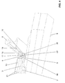
- FIGS. 1 to 4 different views of a track assembly with a protective device 1 according to the present invention are shown.
- the track assembly typically includes a threshold 9 and two rails 8 fixedly connected to the threshold 9 and spaced apart with a gauge S.
- the track assembly further comprises a sill and / or rail-bound device 2.
- This device 2 is for example a balise 2
- the device or the balise can be fastened either at the threshold 9 and / or at the rail 8.
- the device 2 is connected via a screw 5 with the threshold 9, wherein the screw 5 can also serve to fasten the rail 8.
- the inventive protection device 1 is arranged over the device 2, the inventive protection device 1 is arranged.
- the protection device 1 is arranged temporarily and protects the device 2 during a machining of the track arrangement, such as, for example, during ballasting or grading work.
- the track layout is typically stored in a ballast bed with crushed stone.
- the inventive protection device 1 is designed so that it comes to rest between the two rails 8 and covers the overlying the threshold 9 device 2 accordingly and thus protects against external influences. By the cover protects the protective device 1, the device 2 from mechanical influences, such as those arising during maintenance.
- the protective device 1 is designed so that it can be installed temporarily, in particular in the case of said maintenance. For example, such maintenance work is ballasting or leveling the track layout. In this case, before the maintenance operation, the protection device 1 is mounted, and the protection device 1 is removed again after the maintenance operation.
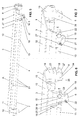
- FIGS. 5 to 7 the protection device 1 is shown in detail.
- the protective device 1 according to the invention for threshold and / or rail-bound devices 2, in particular for balises, will now be explained in detail.
- the protective device 1 comprises a cover 3, which delimits a cavity 4 for receiving the sill and / or rail-bound device 2. Furthermore, the protective device 1 comprises at least two fastening elements 6, 7 connected to the cover 3 for fastening the protective device to a rail 8 and / or a threshold 9.
- the rail 8 and the threshold 9 are components of the track arrangement, as explained above ,
- the cover 3 is preferably formed in one piece.
- At least one of the fastening elements here the fastening element 6, is designed to be movable relative to the cover 3 from a release position into a locking position.
- This movable fastener 6 is thus a lockable or lockable fastener 6, with which the protective device 1 can be fixed to the track assembly.
- the movable fastener may also be referred to as a locking element.
- the fastening element 6 is locked to the cover, wherein the fastening element 6 locks in the locking position, the cover to the track assembly.
- the other fastening element 7 is rigid. This other fastening element 7 is therefore not designed to be movable relative to the cover 3, but is arranged rigidly or firmly to the cover 3.
- the protective device 1 comprises at least one rigidly formed fastening element 7 and at least one movably formed fastening element 6.
- FIG. 5 can be seen that exactly two movable fasteners 6 and exactly two rigid fasteners 7 are arranged.
- the fastening elements 6 and 7 are arranged in pairs at one end region 10, 11 of the cover 3. In a first end region 10, the two movable fastening elements 6 are arranged. In the second end region 11, the two rigid fastening elements 7 are arranged. With respect to the cavity 4, the fastening elements 6, 7 are arranged spaced from each other.
- the above-described pairwise arrangement of the fastening elements 6, 7, has the advantage that the protective device 1 can be particularly easily mounted by hand on the track assembly.
- this assembly is shown.
- the attachment portion 11 is hung with the rigid fasteners 7 on a rail 8.
- the protective device 1 is then pivoted downwards. This is symbolized by the arrow V.
- the movable fasteners 6 can be moved from the release position in the locking position, in which case the fasteners 6 engage around the rail 8 and lock the guard 1 to the track assembly.
- the fastening elements 6, 7 each have a receiving space 18 for receiving and / or partially encompassing parts of the rail 8 and / or a threshold 9.
- the receiving spaces 18 are formed so that the fastening elements 6, 7 engage around the rail foot 19.
- This encompassing the rail foot 19 is in the FIG. 4 shown accordingly.
- the fastener 6 In the FIG. 4 is the fastener 6 in the locked position.
- the fastening element 6 engages around the rail foot 19 with the receiving space 18. In other words, the rail foot 19 protrudes into the receiving space 18.
- the receiving space 18 of the movable fastening element 6 is formed in this embodiment by the cover 3 and a projection 20 on the movable fastening element 6. This encompassing will be explained in detail below.
- the rigid fastening element 7 also surrounds the rail foot 19 with a receiving space 18.
- the receiving space 18 is rigid in the rigid fastening element 7 and is formed in the movable fastening element 6 by the movement of the fastening element 6 in the locking position.
- the cover 3 has two end regions 10, 11. When installed, these end portions 10, 11 are directed against the rails 8.
- the fastening elements 6, 7 are arranged on opposite end regions 10, 11 of the cover 3. In one of the end regions, here in the end region 10, in each case the movable fastening elements 6 are arranged, and in the other of the end regions, here in the end region 11, the rigid fastening elements 7 are respectively arranged. A mixing of the fasteners would also be conceivable.
- the cover 3 extends along a longitudinal axis A and has a length L.
- the length L essentially corresponds to the track width S.
- the expression essentially corresponds to the length L, it is understood that the cover 3 is slightly smaller along the longitudinal axis than the track width S, so that the protective device is simply placed between the two rails 8 of the track arrangement can be.
- the cover 3 has a width B, which extends transversely to the longitudinal axis A and is greater than the width of the threshold 9.
- the cover 3 can cover the threshold 9 optimally.
- the cover 3 has, as in the FIGS. 7 and 6 shown the shape of a U-profile.
- the U-profile includes a base leg 12 and side of the Base leg 12 molded and the base leg 12 adjoining side legs 13. The base leg 12 and the side legs 13 thereby limit the cavity. 4
- the side legs 13 are provided here with several sections and formed partially curved. These different sections are numbered 21. By these bent portions 21 of the cover 3 gives an additional rigidity.
- the fastening elements 6, 7 are on the side legs 13 with the cover 3 in connection. Alternatively, however, the fastening elements 6, 7 can also be connected to the base leg 12 with the cover. A combined arrangement of the fastening elements 6, 7, so the attachment to the side legs 13 and the base leg 12 is conceivable.
- the movable fastening element 6 is pivotable about a pivot axis 14.
- the fastener 6 is shown in the locking position.
- the fastener 6 in the release position. It has been correspondingly pivoted about the pivot axis 14 back.
- the fastener 6 itself has in the present embodiment, the shape of a pawl 22.
- This pawl 22 has the above-mentioned projection 20 which limits the receiving space 18 downwards.
- the pawl 22 is pivotable about the said pivot axis 14, wherein the projection 20 is also pivoted and the rail foot 19 engages around.
- the movable fastening element 6 is mounted twice in the present embodiment.
- the fastening element 6 is mounted on the side leg 13 and on the other hand, the fastening element 6 is mounted on a tab 16.
- the tab 16 is spaced from the side legs 13 and the fastener 6 is located between the side legs 13 and the cover 3.
- the tab 6 is welded, for example, with the cover 3.
- the pivot axis 14 is provided here by a screw 15.
- the screw 15 penetrates with its screw shaft 28 the Side legs 13 of the cover 3 and projects into the tab 16 a.
- the screw 15 provides with its screw shaft 22, the said pivot axis 14 ready.
- the screw 15 engages with a thread in a corresponding thread 23 in the tab 16 a.
- the distance between side legs 13 and tab 16 is dimensioned such that it is slightly larger than the width of the fastening element 6, so that this can be pivoted well.
- the fastener 6 can be locked with a locking member 17 to the cover 3 in the locking position and / or in the release position.
- the Arretierlement 17 here has the shape of a pin. This pin engages in the locking position in a arranged on the tab 16 opening 24 a.
- the pin is mounted in an opening 25 in the fastening element 6.
- the fitter can move the pin 17 in the opening 25 so that it extends through the opening 24. Consequently, the pin thus penetrates the fastening element 6 and the tab 16, wherein a movement between the tab 16, which is integrally formed on the cover 3, and the fastening element 6 is made impossible.
- the release position as in the FIG.
- the fastener 6 is pivoted back.
- the pin 17 is moved out of the opening 24 of the tab 6.
- the tab 16 has a surface 26 for securing the mounting element 6 in the release position. On this surface 26, the pin 17 can rest.
- the movable fastener 6 is secured in the release position and the installer can easily mount the protection device 1.
- the cover has in the present embodiment, a recess 27 for receiving the locking member 17 in the release position.
- the fastening element 6 here has an inclined surface 27.
- This inclined surface 27 is here part of the projection 20 and has the advantage that the fastening element 6 during assembly, should it not be in the release position, is pivoted in the direction of the release position.
- the protection device 1 has the advantage that it can be attached very easily and quickly to a track arrangement.
- the device is well suited for temporary use.
Priority Applications (15)
| Application Number | Priority Date | Filing Date | Title |
|---|---|---|---|
| EP13181821.3A EP2842828B1 (fr) | 2013-08-27 | 2013-08-27 | Dispositif de protection pour dispositifs entre rails, notamment pour dispositifs reliés aux rails et/ou aux seuils |
| SI201330533A SI2842828T1 (sl) | 2013-08-27 | 2013-08-27 | Zaščitna naprava za naprave med tirnicami, še zlasti za naprave, povezane s tirnicami in/ali pragovi |
| PL13181821T PL2842828T3 (pl) | 2013-08-27 | 2013-08-27 | Urządzenie zabezpieczające, chroniące dodatkowe urządzenia techniczne umieszczone między szynami, zwłaszcza urządzenia połączone z samą szyną albo z podkładami szynowymi |
| HUE13181821A HUE033383T2 (en) | 2013-08-27 | 2013-08-27 | Protective device for devices between rails, mainly on rails and / or bottom-mounted devices |
| PT131818213T PT2842828T (pt) | 2013-08-27 | 2013-08-27 | Sistema de protecção para dispositivos entre carris, nomeadamente para dispositivos ligados a carris e/ou ligados a travessas |
| LTEP13181821.3T LT2842828T (lt) | 2013-08-27 | 2013-08-27 | Tarp bėgių esančių įrenginių, konkrečiai - įrenginių, susijusių su bėgiais ir (arba) pabėgiais, apsauginis įtaisas |
| ES13181821.3T ES2615028T3 (es) | 2013-08-27 | 2013-08-27 | Dispositivo de protección para dispositivos entre carriles, en particular para dispositivos unidos a carriles y/o a traviesas |
| DK13181821.3T DK2842828T3 (en) | 2013-08-27 | 2013-08-27 | Protective device for devices between rails, especially for rail and / or rail-bound devices |
| RS20170087A RS55640B1 (sr) | 2013-08-27 | 2013-08-27 | Zaštitni uređaj za uređaje između šina, naročito za uređaje povezane sa šinom i/ili pragom |
| CA2922540A CA2922540A1 (fr) | 2013-08-27 | 2014-08-08 | Dispositif de protection pour des dispositifs installes entre des rails, notamment pour des dispositifs montes sur des rails et/ou sur des traverses de chemin de fer |
| US14/915,369 US20160208442A1 (en) | 2013-08-27 | 2014-08-08 | Protective device for devices between rails, more particularly for rail-mounted and/or sleeper-mounted devices |
| AU2014314468A AU2014314468A1 (en) | 2013-08-27 | 2014-08-08 | Protective device for devices between rails, more particularly for rail-mounted and/or sleeper-mounted devices |
| RU2016108965A RU2653950C2 (ru) | 2013-08-27 | 2014-08-08 | Защитное устройство для расположенных между рельсами устройств, в частности для устройств, соединенных с рельсами и/или шпалами |
| PCT/EP2014/067094 WO2015028288A1 (fr) | 2013-08-27 | 2014-08-08 | Dispositif de protection pour des dispositifs installés entre des rails, notamment pour des dispositifs montés sur des rails et/ou sur des traverses de chemin de fer |
| HRP20170384TT HRP20170384T1 (hr) | 2013-08-27 | 2017-03-08 | Zaštitna naprava za uređaje između tračnica, naročito za uređaj za tračnice i/ili uređaje vezane za pragove |
Applications Claiming Priority (1)
| Application Number | Priority Date | Filing Date | Title |
|---|---|---|---|
| EP13181821.3A EP2842828B1 (fr) | 2013-08-27 | 2013-08-27 | Dispositif de protection pour dispositifs entre rails, notamment pour dispositifs reliés aux rails et/ou aux seuils |
Publications (2)
| Publication Number | Publication Date |
|---|---|
| EP2842828A1 true EP2842828A1 (fr) | 2015-03-04 |
| EP2842828B1 EP2842828B1 (fr) | 2016-12-14 |
Family
ID=49033959
Family Applications (1)
| Application Number | Title | Priority Date | Filing Date |
|---|---|---|---|
| EP13181821.3A Active EP2842828B1 (fr) | 2013-08-27 | 2013-08-27 | Dispositif de protection pour dispositifs entre rails, notamment pour dispositifs reliés aux rails et/ou aux seuils |
Country Status (15)
| Country | Link |
|---|---|
| US (1) | US20160208442A1 (fr) |
| EP (1) | EP2842828B1 (fr) |
| AU (1) | AU2014314468A1 (fr) |
| CA (1) | CA2922540A1 (fr) |
| DK (1) | DK2842828T3 (fr) |
| ES (1) | ES2615028T3 (fr) |
| HR (1) | HRP20170384T1 (fr) |
| HU (1) | HUE033383T2 (fr) |
| LT (1) | LT2842828T (fr) |
| PL (1) | PL2842828T3 (fr) |
| PT (1) | PT2842828T (fr) |
| RS (1) | RS55640B1 (fr) |
| RU (1) | RU2653950C2 (fr) |
| SI (1) | SI2842828T1 (fr) |
| WO (1) | WO2015028288A1 (fr) |
Cited By (3)
| Publication number | Priority date | Publication date | Assignee | Title |
|---|---|---|---|---|
| EP3144201A1 (fr) * | 2015-09-16 | 2017-03-22 | Siemens Schweiz AG | Système et procédé de mise en service et d'arrêt sélectif d'une balise disposée entre les rails d'une voie ferroviaire |
| EP3437954B1 (fr) | 2017-07-31 | 2020-06-17 | Gifas Electric Gesellschaft m.b.H. | Dispositif de protection |
| WO2022130307A1 (fr) * | 2020-12-18 | 2022-06-23 | Scuderi, Joseph | Dispositif et procédé pour la fixation d'objets fonctionnels entre deux rails |
Families Citing this family (5)
| Publication number | Priority date | Publication date | Assignee | Title |
|---|---|---|---|---|
| ES2598882B1 (es) * | 2015-07-29 | 2017-12-14 | Administrador De Infraestructuras Ferroviarias (Adif) | Sistema de sujeción de balizas a traviesas de vías de ferrocarril |
| EP3369861B1 (fr) * | 2017-03-03 | 2019-12-25 | Siemens Mobility AG | Dispositif destiné à agencer un composant d'arrêt automatique de train dans une zone de voie |
| RU174472U1 (ru) * | 2017-05-10 | 2017-10-16 | Федеральное государственное бюджетное образовательное учреждение высшего образования "Петербургский государственный университет путей сообщения Императора Александра I" | Отбойный брус для железнодорожного пути |
| RU196824U1 (ru) * | 2019-11-29 | 2020-03-17 | Открытое Акционерное Общество "Российские Железные Дороги" | Брус отбойный для защиты инженерного сооружения внутри рельсовой колеи |
| US11406099B2 (en) * | 2020-02-12 | 2022-08-09 | Lance Corbin | Animal barrier for railroad tracks |
Citations (6)
| Publication number | Priority date | Publication date | Assignee | Title |
|---|---|---|---|---|
| US5507434A (en) * | 1994-06-16 | 1996-04-16 | Harmon Industries, Inc. | Clamp mount for concrete ties |
| EP0856608A1 (fr) * | 1997-01-31 | 1998-08-05 | Siemens Schweiz AG (Siemens Suisse SA) (Siemens Svizzera SA) Siemens Switzerland Ltd) | Traverse modulaire creux pour un mécanisme d'aiguillage de voies ferrées |
| GB2347456A (en) * | 1998-12-03 | 2000-09-06 | Multiclip Co Ltd | Securing equipment to a railway rail foundation |
| WO2011141119A1 (fr) * | 2010-05-12 | 2011-11-17 | Db Netz Ag | Dispositif de fixation et de protection d'une eurobalise |
| WO2011141118A1 (fr) * | 2010-05-12 | 2011-11-17 | Db Netz Ag | Dispositif de fixation et de protection d'une eurobalise |
| EP2481851A1 (fr) * | 2011-01-27 | 2012-08-01 | DMA S.r.l. | Plateforme pour une utilisation dans un système de mise en place et/ou suppression d'une charge utile sur des rails de chemin de fer et procédé de mise en place et/ou suppression correspondant |
Family Cites Families (1)
| Publication number | Priority date | Publication date | Assignee | Title |
|---|---|---|---|---|
| US1879614A (en) * | 1929-07-11 | 1932-09-27 | Associated Electric Lab Inc | Train stop system |
-
2013
- 2013-08-27 EP EP13181821.3A patent/EP2842828B1/fr active Active
- 2013-08-27 DK DK13181821.3T patent/DK2842828T3/en active
- 2013-08-27 PL PL13181821T patent/PL2842828T3/pl unknown
- 2013-08-27 LT LTEP13181821.3T patent/LT2842828T/lt unknown
- 2013-08-27 SI SI201330533A patent/SI2842828T1/sl unknown
- 2013-08-27 ES ES13181821.3T patent/ES2615028T3/es active Active
- 2013-08-27 RS RS20170087A patent/RS55640B1/sr unknown
- 2013-08-27 HU HUE13181821A patent/HUE033383T2/en unknown
- 2013-08-27 PT PT131818213T patent/PT2842828T/pt unknown
-
2014
- 2014-08-08 CA CA2922540A patent/CA2922540A1/fr not_active Abandoned
- 2014-08-08 WO PCT/EP2014/067094 patent/WO2015028288A1/fr active Application Filing
- 2014-08-08 US US14/915,369 patent/US20160208442A1/en not_active Abandoned
- 2014-08-08 RU RU2016108965A patent/RU2653950C2/ru not_active IP Right Cessation
- 2014-08-08 AU AU2014314468A patent/AU2014314468A1/en not_active Abandoned
-
2017
- 2017-03-08 HR HRP20170384TT patent/HRP20170384T1/hr unknown
Patent Citations (6)
| Publication number | Priority date | Publication date | Assignee | Title |
|---|---|---|---|---|
| US5507434A (en) * | 1994-06-16 | 1996-04-16 | Harmon Industries, Inc. | Clamp mount for concrete ties |
| EP0856608A1 (fr) * | 1997-01-31 | 1998-08-05 | Siemens Schweiz AG (Siemens Suisse SA) (Siemens Svizzera SA) Siemens Switzerland Ltd) | Traverse modulaire creux pour un mécanisme d'aiguillage de voies ferrées |
| GB2347456A (en) * | 1998-12-03 | 2000-09-06 | Multiclip Co Ltd | Securing equipment to a railway rail foundation |
| WO2011141119A1 (fr) * | 2010-05-12 | 2011-11-17 | Db Netz Ag | Dispositif de fixation et de protection d'une eurobalise |
| WO2011141118A1 (fr) * | 2010-05-12 | 2011-11-17 | Db Netz Ag | Dispositif de fixation et de protection d'une eurobalise |
| EP2481851A1 (fr) * | 2011-01-27 | 2012-08-01 | DMA S.r.l. | Plateforme pour une utilisation dans un système de mise en place et/ou suppression d'une charge utile sur des rails de chemin de fer et procédé de mise en place et/ou suppression correspondant |
Cited By (3)
| Publication number | Priority date | Publication date | Assignee | Title |
|---|---|---|---|---|
| EP3144201A1 (fr) * | 2015-09-16 | 2017-03-22 | Siemens Schweiz AG | Système et procédé de mise en service et d'arrêt sélectif d'une balise disposée entre les rails d'une voie ferroviaire |
| EP3437954B1 (fr) | 2017-07-31 | 2020-06-17 | Gifas Electric Gesellschaft m.b.H. | Dispositif de protection |
| WO2022130307A1 (fr) * | 2020-12-18 | 2022-06-23 | Scuderi, Joseph | Dispositif et procédé pour la fixation d'objets fonctionnels entre deux rails |
Also Published As
| Publication number | Publication date |
|---|---|
| HUE033383T2 (en) | 2017-11-28 |
| RS55640B1 (sr) | 2017-06-30 |
| PL2842828T3 (pl) | 2017-06-30 |
| EP2842828B1 (fr) | 2016-12-14 |
| SI2842828T1 (sl) | 2017-03-31 |
| PT2842828T (pt) | 2017-03-20 |
| CA2922540A1 (fr) | 2015-03-05 |
| WO2015028288A1 (fr) | 2015-03-05 |
| RU2653950C2 (ru) | 2018-05-15 |
| US20160208442A1 (en) | 2016-07-21 |
| DK2842828T3 (en) | 2017-03-13 |
| HRP20170384T1 (hr) | 2017-05-19 |
| LT2842828T (lt) | 2017-02-10 |
| RU2016108965A3 (fr) | 2018-03-13 |
| ES2615028T3 (es) | 2017-06-05 |
| AU2014314468A1 (en) | 2016-03-17 |
| RU2016108965A (ru) | 2017-10-03 |
Similar Documents
| Publication | Publication Date | Title |
|---|---|---|
| EP2842828B1 (fr) | Dispositif de protection pour dispositifs entre rails, notamment pour dispositifs reliés aux rails et/ou aux seuils | |
| DE4315200C2 (de) | Querschwelle mit Verstellvorrichtung für Weichenzungen | |
| WO2008113610A2 (fr) | Dispositif servant à fixer des objets | |
| DE102018103435A1 (de) | Dachträger | |
| EP2137365B1 (fr) | Sabot de guidage et combinaison d'un sabot de guidage avec un profilé d'escalade | |
| EP3356599B1 (fr) | Système et point de fixation permettant la fixation sans vis d'un rail pour un véhicule ferroviaire | |
| EP2039644B1 (fr) | Cabine d'ascenseur | |
| DE1534120B1 (de) | Eisenbahnquerschwelle | |
| DE202011001106U1 (de) | System zum horizontalen Ausrichten eines Gleisrostes einer festen Schienenfahrbahn | |
| EP3424795A1 (fr) | Dispositif de fixation d'un commutateur de rails sur un rail | |
| DE2922543C3 (de) | Klammerverbindung bei einem Fahrzeug mit einer anzubringenden Einheit, insbesondere einem Differentialgetriebe | |
| DE102012210544A1 (de) | Wischadaptervorrichtung | |
| EP0825050B1 (fr) | Rancher entre une membrure supérieure et le châssis d'un véhicule | |
| EP4050156A1 (fr) | Dispositif de recouvrement d'au moins un composant d'un point de fixation de rail et point de fixation | |
| EP3276112A1 (fr) | Dispositif de verrouillage de porte | |
| DE202014010270U1 (de) | System zum Richten eines Gleises einer festen Schienenfahrbahn | |
| DE202007016196U1 (de) | Gleisanlage, insbesondere Baugleisanlage für einen Tunnelausbau | |
| DE19962519C1 (de) | Halterung für einen Verschlusskasten | |
| DE102014003412B3 (de) | Vorrichtung zur lösbaren, formschlüssigen Befestigung einer Teleskopstütze an einer Wohnkabine | |
| EP2626242B1 (fr) | Procédé de déplacement en continu d'au moins un élément d'arrêt d'un élément de verrouillage | |
| DE10124842B4 (de) | Stählerne Eisenbahnbrücke sowie Aufnahmesystem für Schienen | |
| DE1919340A1 (de) | Sicherungsvorrichtung | |
| DE102020131198A1 (de) | Sitzkonsole und Fahrzeugsitz mit einer Sitzkonsole | |
| DE202014002188U1 (de) | Vorrichtung zur Befestigung einer Teleskopstütze | |
| DE2811622A1 (de) | Stempelkopfarretierung an kappen- oder unterzugprofilen des streb- und streckenausbaus im bergbau |
Legal Events
| Date | Code | Title | Description |
|---|---|---|---|
| 17P | Request for examination filed |
Effective date: 20130827 |
|
| AK | Designated contracting states |
Kind code of ref document: A1 Designated state(s): AL AT BE BG CH CY CZ DE DK EE ES FI FR GB GR HR HU IE IS IT LI LT LU LV MC MK MT NL NO PL PT RO RS SE SI SK SM TR |
|
| AX | Request for extension of the european patent |
Extension state: BA ME |
|
| PUAI | Public reference made under article 153(3) epc to a published international application that has entered the european phase |
Free format text: ORIGINAL CODE: 0009012 |
|
| R17P | Request for examination filed (corrected) |
Effective date: 20150811 |
|
| RBV | Designated contracting states (corrected) |
Designated state(s): AL AT BE BG CH CY CZ DE DK EE ES FI FR GB GR HR HU IE IS IT LI LT LU LV MC MK MT NL NO PL PT RO RS SE SI SK SM TR |
|
| GRAP | Despatch of communication of intention to grant a patent |
Free format text: ORIGINAL CODE: EPIDOSNIGR1 |
|
| INTG | Intention to grant announced |
Effective date: 20160705 |
|
| GRAS | Grant fee paid |
Free format text: ORIGINAL CODE: EPIDOSNIGR3 |
|
| GRAA | (expected) grant |
Free format text: ORIGINAL CODE: 0009210 |
|
| AK | Designated contracting states |
Kind code of ref document: B1 Designated state(s): AL AT BE BG CH CY CZ DE DK EE ES FI FR GB GR HR HU IE IS IT LI LT LU LV MC MK MT NL NO PL PT RO RS SE SI SK SM TR |
|
| REG | Reference to a national code |
Ref country code: GB Ref legal event code: FG4D Free format text: NOT ENGLISH |
|
| REG | Reference to a national code |
Ref country code: CH Ref legal event code: EP |
|
| REG | Reference to a national code |
Ref country code: IE Ref legal event code: FG4D Free format text: LANGUAGE OF EP DOCUMENT: GERMAN |
|
| REG | Reference to a national code |
Ref country code: AT Ref legal event code: REF Ref document number: 853280 Country of ref document: AT Kind code of ref document: T Effective date: 20170115 |
|
| REG | Reference to a national code |
Ref country code: DE Ref legal event code: R096 Ref document number: 502013005717 Country of ref document: DE |
|
| REG | Reference to a national code |
Ref country code: CH Ref legal event code: NV Representative=s name: ISLER AND PEDRAZZINI AG, CH |
|
| REG | Reference to a national code |
Ref country code: HR Ref legal event code: TUEP Ref document number: P20170384 Country of ref document: HR |
|
| REG | Reference to a national code |
Ref country code: DK Ref legal event code: T3 Effective date: 20170309 |
|
| REG | Reference to a national code |
Ref country code: SE Ref legal event code: TRGR |
|
| REG | Reference to a national code |
Ref country code: NL Ref legal event code: FP |
|
| REG | Reference to a national code |
Ref country code: PT Ref legal event code: SC4A Ref document number: 2842828 Country of ref document: PT Date of ref document: 20170320 Kind code of ref document: T Free format text: AVAILABILITY OF NATIONAL TRANSLATION Effective date: 20170314 |
|
| REG | Reference to a national code |
Ref country code: EE Ref legal event code: FG4A Ref document number: E013323 Country of ref document: EE Effective date: 20170215 |
|
| REG | Reference to a national code |
Ref country code: NO Ref legal event code: T2 Effective date: 20161214 |
|
| REG | Reference to a national code |
Ref country code: HR Ref legal event code: T1PR Ref document number: P20170384 Country of ref document: HR |
|
| REG | Reference to a national code |
Ref country code: ES Ref legal event code: FG2A Ref document number: 2615028 Country of ref document: ES Kind code of ref document: T3 Effective date: 20170605 |
|
| PGFP | Annual fee paid to national office [announced via postgrant information from national office to epo] |
Ref country code: TR Payment date: 20170310 Year of fee payment: 5 |
|
| PG25 | Lapsed in a contracting state [announced via postgrant information from national office to epo] |
Ref country code: IS Free format text: LAPSE BECAUSE OF FAILURE TO SUBMIT A TRANSLATION OF THE DESCRIPTION OR TO PAY THE FEE WITHIN THE PRESCRIBED TIME-LIMIT Effective date: 20170414 |
|
| REG | Reference to a national code |
Ref country code: FR Ref legal event code: PLFP Year of fee payment: 5 |
|
| PG25 | Lapsed in a contracting state [announced via postgrant information from national office to epo] |
Ref country code: SM Free format text: LAPSE BECAUSE OF FAILURE TO SUBMIT A TRANSLATION OF THE DESCRIPTION OR TO PAY THE FEE WITHIN THE PRESCRIBED TIME-LIMIT Effective date: 20161214 |
|
| REG | Reference to a national code |
Ref country code: DE Ref legal event code: R097 Ref document number: 502013005717 Country of ref document: DE |
|
| PLBE | No opposition filed within time limit |
Free format text: ORIGINAL CODE: 0009261 |
|
| REG | Reference to a national code |
Ref country code: RO Ref legal event code: EPE |
|
| STAA | Information on the status of an ep patent application or granted ep patent |
Free format text: STATUS: NO OPPOSITION FILED WITHIN TIME LIMIT |
|
| 26N | No opposition filed |
Effective date: 20170915 |
|
| REG | Reference to a national code |
Ref country code: HU Ref legal event code: AG4A Ref document number: E033383 Country of ref document: HU |
|
| REG | Reference to a national code |
Ref country code: HR Ref legal event code: PBON Ref document number: P20170384 Country of ref document: HR Effective date: 20170827 |
|
| REG | Reference to a national code |
Ref country code: EE Ref legal event code: MM4A Ref document number: E013323 Country of ref document: EE Effective date: 20170831 |
|
| REG | Reference to a national code |
Ref country code: LT Ref legal event code: MM4D Effective date: 20170827 |
|
| PG25 | Lapsed in a contracting state [announced via postgrant information from national office to epo] |
Ref country code: MC Free format text: LAPSE BECAUSE OF FAILURE TO SUBMIT A TRANSLATION OF THE DESCRIPTION OR TO PAY THE FEE WITHIN THE PRESCRIBED TIME-LIMIT Effective date: 20161214 |
|
| PG25 | Lapsed in a contracting state [announced via postgrant information from national office to epo] |
Ref country code: HU Free format text: LAPSE BECAUSE OF NON-PAYMENT OF DUE FEES Effective date: 20170828 Ref country code: CZ Free format text: LAPSE BECAUSE OF NON-PAYMENT OF DUE FEES Effective date: 20170827 Ref country code: LT Free format text: LAPSE BECAUSE OF NON-PAYMENT OF DUE FEES Effective date: 20170827 |
|
| REG | Reference to a national code |
Ref country code: SK Ref legal event code: MM4A Ref document number: E 23469 Country of ref document: SK Effective date: 20170827 |
|
| PG25 | Lapsed in a contracting state [announced via postgrant information from national office to epo] |
Ref country code: RS Free format text: LAPSE BECAUSE OF NON-PAYMENT OF DUE FEES Effective date: 20180305 Ref country code: SI Free format text: LAPSE BECAUSE OF NON-PAYMENT OF DUE FEES Effective date: 20170828 Ref country code: HR Free format text: LAPSE BECAUSE OF NON-PAYMENT OF DUE FEES Effective date: 20170827 Ref country code: LV Free format text: LAPSE BECAUSE OF NON-PAYMENT OF DUE FEES Effective date: 20170827 Ref country code: EE Free format text: LAPSE BECAUSE OF NON-PAYMENT OF DUE FEES Effective date: 20170831 Ref country code: GR Free format text: LAPSE BECAUSE OF NON-PAYMENT OF DUE FEES Effective date: 20180305 Ref country code: SK Free format text: LAPSE BECAUSE OF NON-PAYMENT OF DUE FEES Effective date: 20170827 |
|
| REG | Reference to a national code |
Ref country code: SI Ref legal event code: KO00 Effective date: 20180410 |
|
| REG | Reference to a national code |
Ref country code: FR Ref legal event code: PLFP Year of fee payment: 6 |
|
| PG25 | Lapsed in a contracting state [announced via postgrant information from national office to epo] |
Ref country code: MT Free format text: LAPSE BECAUSE OF FAILURE TO SUBMIT A TRANSLATION OF THE DESCRIPTION OR TO PAY THE FEE WITHIN THE PRESCRIBED TIME-LIMIT Effective date: 20161214 |
|
| PGFP | Annual fee paid to national office [announced via postgrant information from national office to epo] |
Ref country code: LU Payment date: 20180821 Year of fee payment: 6 |
|
| PGFP | Annual fee paid to national office [announced via postgrant information from national office to epo] |
Ref country code: IE Payment date: 20180828 Year of fee payment: 6 Ref country code: DE Payment date: 20180823 Year of fee payment: 6 Ref country code: ES Payment date: 20180921 Year of fee payment: 6 Ref country code: NO Payment date: 20180827 Year of fee payment: 6 Ref country code: IT Payment date: 20180823 Year of fee payment: 6 Ref country code: FR Payment date: 20180827 Year of fee payment: 6 Ref country code: NL Payment date: 20180821 Year of fee payment: 6 |
|
| PGFP | Annual fee paid to national office [announced via postgrant information from national office to epo] |
Ref country code: FI Payment date: 20180822 Year of fee payment: 6 Ref country code: SE Payment date: 20180823 Year of fee payment: 6 Ref country code: BE Payment date: 20180821 Year of fee payment: 6 Ref country code: AT Payment date: 20180822 Year of fee payment: 6 Ref country code: DK Payment date: 20180823 Year of fee payment: 6 Ref country code: CH Payment date: 20180813 Year of fee payment: 6 Ref country code: GB Payment date: 20180822 Year of fee payment: 6 |
|
| PGFP | Annual fee paid to national office [announced via postgrant information from national office to epo] |
Ref country code: PT Payment date: 20180719 Year of fee payment: 6 |
|
| REG | Reference to a national code |
Ref country code: DE Ref legal event code: R082 Ref document number: 502013005717 Country of ref document: DE Representative=s name: SCHIFFER, AXEL, DIPL.-PHYS.UNIV. DR.RER.NAT., DE |
|
| PG25 | Lapsed in a contracting state [announced via postgrant information from national office to epo] |
Ref country code: BG Free format text: LAPSE BECAUSE OF NON-PAYMENT OF DUE FEES Effective date: 20180306 |
|
| PG25 | Lapsed in a contracting state [announced via postgrant information from national office to epo] |
Ref country code: PL Free format text: LAPSE BECAUSE OF NON-PAYMENT OF DUE FEES Effective date: 20170827 |
|
| PG25 | Lapsed in a contracting state [announced via postgrant information from national office to epo] |
Ref country code: RO Free format text: LAPSE BECAUSE OF NON-PAYMENT OF DUE FEES Effective date: 20161214 |
|
| PG25 | Lapsed in a contracting state [announced via postgrant information from national office to epo] |
Ref country code: CY Free format text: LAPSE BECAUSE OF FAILURE TO SUBMIT A TRANSLATION OF THE DESCRIPTION OR TO PAY THE FEE WITHIN THE PRESCRIBED TIME-LIMIT Effective date: 20161214 |
|
| REG | Reference to a national code |
Ref country code: DE Ref legal event code: R119 Ref document number: 502013005717 Country of ref document: DE |
|
| REG | Reference to a national code |
Ref country code: NO Ref legal event code: MMEP |
|
| REG | Reference to a national code |
Ref country code: FI Ref legal event code: MAE |
|
| REG | Reference to a national code |
Ref country code: DK Ref legal event code: EBP Effective date: 20190831 |
|
| REG | Reference to a national code |
Ref country code: NL Ref legal event code: MM Effective date: 20190901 |
|
| REG | Reference to a national code |
Ref country code: AT Ref legal event code: MM01 Ref document number: 853280 Country of ref document: AT Kind code of ref document: T Effective date: 20190827 |
|
| REG | Reference to a national code |
Ref country code: SE Ref legal event code: EUG |
|
| GBPC | Gb: european patent ceased through non-payment of renewal fee |
Effective date: 20190827 |
|
| PG25 | Lapsed in a contracting state [announced via postgrant information from national office to epo] |
Ref country code: FI Free format text: LAPSE BECAUSE OF NON-PAYMENT OF DUE FEES Effective date: 20190827 Ref country code: NO Free format text: LAPSE BECAUSE OF NON-PAYMENT OF DUE FEES Effective date: 20190831 Ref country code: PT Free format text: LAPSE BECAUSE OF NON-PAYMENT OF DUE FEES Effective date: 20200227 Ref country code: SE Free format text: LAPSE BECAUSE OF NON-PAYMENT OF DUE FEES Effective date: 20190828 Ref country code: AT Free format text: LAPSE BECAUSE OF NON-PAYMENT OF DUE FEES Effective date: 20190827 |
|
| PG25 | Lapsed in a contracting state [announced via postgrant information from national office to epo] |
Ref country code: LU Free format text: LAPSE BECAUSE OF NON-PAYMENT OF DUE FEES Effective date: 20190827 Ref country code: CH Free format text: LAPSE BECAUSE OF NON-PAYMENT OF DUE FEES Effective date: 20190831 Ref country code: LI Free format text: LAPSE BECAUSE OF NON-PAYMENT OF DUE FEES Effective date: 20190831 |
|
| REG | Reference to a national code |
Ref country code: BE Ref legal event code: MM Effective date: 20190831 |
|
| PG25 | Lapsed in a contracting state [announced via postgrant information from national office to epo] |
Ref country code: IE Free format text: LAPSE BECAUSE OF NON-PAYMENT OF DUE FEES Effective date: 20190827 Ref country code: NL Free format text: LAPSE BECAUSE OF NON-PAYMENT OF DUE FEES Effective date: 20190901 Ref country code: DE Free format text: LAPSE BECAUSE OF NON-PAYMENT OF DUE FEES Effective date: 20200303 Ref country code: DK Free format text: LAPSE BECAUSE OF NON-PAYMENT OF DUE FEES Effective date: 20190831 Ref country code: AL Free format text: LAPSE BECAUSE OF FAILURE TO SUBMIT A TRANSLATION OF THE DESCRIPTION OR TO PAY THE FEE WITHIN THE PRESCRIBED TIME-LIMIT Effective date: 20161214 Ref country code: FR Free format text: LAPSE BECAUSE OF NON-PAYMENT OF DUE FEES Effective date: 20190831 |
|
| PG25 | Lapsed in a contracting state [announced via postgrant information from national office to epo] |
Ref country code: BE Free format text: LAPSE BECAUSE OF NON-PAYMENT OF DUE FEES Effective date: 20190831 Ref country code: IT Free format text: LAPSE BECAUSE OF NON-PAYMENT OF DUE FEES Effective date: 20190827 Ref country code: GB Free format text: LAPSE BECAUSE OF NON-PAYMENT OF DUE FEES Effective date: 20190827 |
|
| REG | Reference to a national code |
Ref country code: ES Ref legal event code: FD2A Effective date: 20210107 |
|
| PG25 | Lapsed in a contracting state [announced via postgrant information from national office to epo] |
Ref country code: ES Free format text: LAPSE BECAUSE OF NON-PAYMENT OF DUE FEES Effective date: 20190828 |
|
| PG25 | Lapsed in a contracting state [announced via postgrant information from national office to epo] |
Ref country code: TR Free format text: LAPSE BECAUSE OF NON-PAYMENT OF DUE FEES Effective date: 20180827 |