EP2842828A1 - Protection device for devices between rails, in particular for rail and/or sleeper-bound devices - Google Patents
Protection device for devices between rails, in particular for rail and/or sleeper-bound devices Download PDFInfo
- Publication number
- EP2842828A1 EP2842828A1 EP13181821.3A EP13181821A EP2842828A1 EP 2842828 A1 EP2842828 A1 EP 2842828A1 EP 13181821 A EP13181821 A EP 13181821A EP 2842828 A1 EP2842828 A1 EP 2842828A1
- Authority
- EP
- European Patent Office
- Prior art keywords
- cover
- rail
- protective device
- fastening elements
- threshold
- Prior art date
- Legal status (The legal status is an assumption and is not a legal conclusion. Google has not performed a legal analysis and makes no representation as to the accuracy of the status listed.)
- Granted
Links
Images


Classifications
-
- E—FIXED CONSTRUCTIONS
- E01—CONSTRUCTION OF ROADS, RAILWAYS, OR BRIDGES
- E01B—PERMANENT WAY; PERMANENT-WAY TOOLS; MACHINES FOR MAKING RAILWAYS OF ALL KINDS
- E01B26/00—Tracks or track components not covered by any one of the preceding groups
- E01B26/005—Means for fixing posts, barriers, fences or the like to rails
-
- B—PERFORMING OPERATIONS; TRANSPORTING
- B61—RAILWAYS
- B61L—GUIDING RAILWAY TRAFFIC; ENSURING THE SAFETY OF RAILWAY TRAFFIC
- B61L3/00—Devices along the route for controlling devices on the vehicle or vehicle train, e.g. to release brake, to operate a warning signal
- B61L3/02—Devices along the route for controlling devices on the vehicle or vehicle train, e.g. to release brake, to operate a warning signal at selected places along the route, e.g. intermittent control simultaneous mechanical and electrical control
- B61L3/08—Devices along the route for controlling devices on the vehicle or vehicle train, e.g. to release brake, to operate a warning signal at selected places along the route, e.g. intermittent control simultaneous mechanical and electrical control controlling electrically
- B61L3/12—Devices along the route for controlling devices on the vehicle or vehicle train, e.g. to release brake, to operate a warning signal at selected places along the route, e.g. intermittent control simultaneous mechanical and electrical control controlling electrically using magnetic or electrostatic induction; using radio waves
- B61L3/126—Constructional details
-
- B—PERFORMING OPERATIONS; TRANSPORTING
- B61—RAILWAYS
- B61L—GUIDING RAILWAY TRAFFIC; ENSURING THE SAFETY OF RAILWAY TRAFFIC
- B61L3/00—Devices along the route for controlling devices on the vehicle or vehicle train, e.g. to release brake, to operate a warning signal
- B61L3/02—Devices along the route for controlling devices on the vehicle or vehicle train, e.g. to release brake, to operate a warning signal at selected places along the route, e.g. intermittent control simultaneous mechanical and electrical control
- B61L3/08—Devices along the route for controlling devices on the vehicle or vehicle train, e.g. to release brake, to operate a warning signal at selected places along the route, e.g. intermittent control simultaneous mechanical and electrical control controlling electrically
- B61L3/12—Devices along the route for controlling devices on the vehicle or vehicle train, e.g. to release brake, to operate a warning signal at selected places along the route, e.g. intermittent control simultaneous mechanical and electrical control controlling electrically using magnetic or electrostatic induction; using radio waves
- B61L3/121—Devices along the route for controlling devices on the vehicle or vehicle train, e.g. to release brake, to operate a warning signal at selected places along the route, e.g. intermittent control simultaneous mechanical and electrical control controlling electrically using magnetic or electrostatic induction; using radio waves using magnetic induction
-
- B—PERFORMING OPERATIONS; TRANSPORTING
- B61—RAILWAYS
- B61L—GUIDING RAILWAY TRAFFIC; ENSURING THE SAFETY OF RAILWAY TRAFFIC
- B61L3/00—Devices along the route for controlling devices on the vehicle or vehicle train, e.g. to release brake, to operate a warning signal
- B61L3/02—Devices along the route for controlling devices on the vehicle or vehicle train, e.g. to release brake, to operate a warning signal at selected places along the route, e.g. intermittent control simultaneous mechanical and electrical control
- B61L3/08—Devices along the route for controlling devices on the vehicle or vehicle train, e.g. to release brake, to operate a warning signal at selected places along the route, e.g. intermittent control simultaneous mechanical and electrical control controlling electrically
- B61L3/12—Devices along the route for controlling devices on the vehicle or vehicle train, e.g. to release brake, to operate a warning signal at selected places along the route, e.g. intermittent control simultaneous mechanical and electrical control controlling electrically using magnetic or electrostatic induction; using radio waves
- B61L3/125—Devices along the route for controlling devices on the vehicle or vehicle train, e.g. to release brake, to operate a warning signal at selected places along the route, e.g. intermittent control simultaneous mechanical and electrical control controlling electrically using magnetic or electrostatic induction; using radio waves using short-range radio transmission
Definitions
- the present invention relates to a protection device for devices between the rails, in particular for rail and / or threshold-bound devices, such as balises, according to the preamble of claim 1.
- railway engineering railway sleepers are not only used for fastening rails, but also for the attachment of other railway technical devices.
- balises are generally well protected against the burdens of railway traffic by their own construction.
- the invention has for its object to provide a device which overcomes the disadvantages of the prior art.
- a device is to be specified with which improved ballast or leveling around a threshold, which is equipped with a sill or rail-mounted device, such as a balise, can be achieved.
- a protective device is used to protect sill or rail-bound devices, especially for balises. These devices are located between two railroad tracks.
- the protection device includes a cover defining a cavity for receiving the sill or rail-bound device, and at least two fasteners associated with the cover for securing the protection device to a rail and / or a sill.
- the cavity is limited in particular upwards. In other words, the cavity is preferably at least partially bounded by the cover.
- At least one of the fastening elements is designed to be movable relative to the cover from a release position into a locking position.
- the guard With this movable fastener, the guard can be locked to the rail or to the threshold.
- the protection device can be temporarily fixed during maintenance work, in particular during ballast work, on the rail and / or sleeper. After maintenance work, the protection device can be removed again from the rail and / or the threshold.
- the movable fastener may also be referred to as a locking element.
- the protective device In the locking position, the protective device can be locked or locked relative to a track arrangement with the movable fastening element.
- the fastening element is locked to the cover, wherein the fastening element in the locking position locks the cover or the protective device to the track arrangement.
- the movable fastening element is preferably designed such that this Hand from the release position in the locking position and back from the Arretierlage in the release position is movable.
- the fitter of the protection device can thus fix this without the aid of a tool on a track assembly, in particular on a rail and / or a threshold.
- At least one of the fastening elements is rigid.
- rigid and movable fastening elements are present. This has the advantage during assembly of the protective device that the installer must actively manipulate only the movable fasteners.
- the fastening elements have a receiving space for receiving and / or partially encompassing parts of a rail and / or a threshold.
- the cover has two end portions, which are directed in the installed state against the rails, wherein the fastening elements are arranged at opposite end portions of the cover.
- the movable fastening elements are arranged in one of the end regions and the rigid fastening elements are arranged in the other of the end regions. This allows the rigid fasteners to be hung on one side and the fasteners to be locked on the other side.
- the cover extends along a longitudinal axis and has a length which substantially corresponds to the gauge. Further, the cover preferably has a width transverse to the longitudinal axis, which is greater than the width of the threshold.
- the rail and / or threshold-bound device can be covered particularly well.
- the protection device can be used in various rail and / or threshold-bound devices.
- the cover has the shape of a U-profile with a base leg and with the side leg adjoining the base leg on both sides, the base leg and the side legs delimiting the said cavity.
- the U-profile preferably extends along the said longitudinal axis.
- the fastening elements are preferably connected to the cover via the side legs and / or the base leg.
- the movable fastening element is pivotable about a pivot axis.
- the movable fastener may also be referred to as latching pawl, about which pivot axis is pivotable.
- a rigidly associated with the cover tab is arranged, wherein the movable fastening element between side legs and tab is placed.
- the said pivot axis is preferably provided by a bolt or screw extending through the side leg of the cover, the bolt or screw preferably extending through the side leg and the fastener to the tab.
- the movable fastening element can be locked with a locking element for covering in the locking position and / or in the release position.
- the locking element is for example a locking pin, which can be passed through an opening on the fastening element and through an opening on the cover or on the said tab.
- the locking pin can be attached via a captive to the cover or on the fastener.
- the protective device is made of metal, in particular of steel, particularly preferably of stainless steel.
- the protective device can also be made of aluminum.
- the protective device may also be made of plastic.
- a track assembly comprises a threshold of two fixedly connected to the threshold and with a track spaced apart rails and a sill and / or rail-bound device and an over the sill and / or rail-mounted device between the rails arranged protective device as described above.
- the threshold or rail-bound device is covered by the protection device, whereby the track arrangement can be machined, for example, during a ballasting operation or the leveling operation.
- Said fastening elements are preferably connectable with rail feet of said rail.
- the protective device can be hooked onto the rail.
- a method for mounting a protective device as described above is characterized in that the protective device is connected to said at least one fastening element with the rail and / or the threshold. Particularly preferably, the protective device is locked to the track arrangement via the movable fastening element.
- a method for maintaining a track arrangement, in particular for ballasting or leveling the track arrangement, as described above, is characterized in that before the steps for maintenance, in particular before ballasting or leveling, a protective device is mounted above the sill or rail-bound device and after the steps taken for maintenance, in particular after the successful graveling or leveling said protective device is removed again.
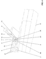
- FIGS. 1 to 4 different views of a track assembly with a protective device 1 according to the present invention are shown.
- the track assembly typically includes a threshold 9 and two rails 8 fixedly connected to the threshold 9 and spaced apart with a gauge S.
- the track assembly further comprises a sill and / or rail-bound device 2.
- This device 2 is for example a balise 2
- the device or the balise can be fastened either at the threshold 9 and / or at the rail 8.
- the device 2 is connected via a screw 5 with the threshold 9, wherein the screw 5 can also serve to fasten the rail 8.
- the inventive protection device 1 is arranged over the device 2, the inventive protection device 1 is arranged.
- the protection device 1 is arranged temporarily and protects the device 2 during a machining of the track arrangement, such as, for example, during ballasting or grading work.
- the track layout is typically stored in a ballast bed with crushed stone.
- the inventive protection device 1 is designed so that it comes to rest between the two rails 8 and covers the overlying the threshold 9 device 2 accordingly and thus protects against external influences. By the cover protects the protective device 1, the device 2 from mechanical influences, such as those arising during maintenance.
- the protective device 1 is designed so that it can be installed temporarily, in particular in the case of said maintenance. For example, such maintenance work is ballasting or leveling the track layout. In this case, before the maintenance operation, the protection device 1 is mounted, and the protection device 1 is removed again after the maintenance operation.
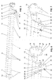
- FIGS. 5 to 7 the protection device 1 is shown in detail.
- the protective device 1 according to the invention for threshold and / or rail-bound devices 2, in particular for balises, will now be explained in detail.
- the protective device 1 comprises a cover 3, which delimits a cavity 4 for receiving the sill and / or rail-bound device 2. Furthermore, the protective device 1 comprises at least two fastening elements 6, 7 connected to the cover 3 for fastening the protective device to a rail 8 and / or a threshold 9.
- the rail 8 and the threshold 9 are components of the track arrangement, as explained above ,
- the cover 3 is preferably formed in one piece.
- At least one of the fastening elements here the fastening element 6, is designed to be movable relative to the cover 3 from a release position into a locking position.
- This movable fastener 6 is thus a lockable or lockable fastener 6, with which the protective device 1 can be fixed to the track assembly.
- the movable fastener may also be referred to as a locking element.
- the fastening element 6 is locked to the cover, wherein the fastening element 6 locks in the locking position, the cover to the track assembly.
- the other fastening element 7 is rigid. This other fastening element 7 is therefore not designed to be movable relative to the cover 3, but is arranged rigidly or firmly to the cover 3.
- the protective device 1 comprises at least one rigidly formed fastening element 7 and at least one movably formed fastening element 6.
- FIG. 5 can be seen that exactly two movable fasteners 6 and exactly two rigid fasteners 7 are arranged.
- the fastening elements 6 and 7 are arranged in pairs at one end region 10, 11 of the cover 3. In a first end region 10, the two movable fastening elements 6 are arranged. In the second end region 11, the two rigid fastening elements 7 are arranged. With respect to the cavity 4, the fastening elements 6, 7 are arranged spaced from each other.
- the above-described pairwise arrangement of the fastening elements 6, 7, has the advantage that the protective device 1 can be particularly easily mounted by hand on the track assembly.
- this assembly is shown.
- the attachment portion 11 is hung with the rigid fasteners 7 on a rail 8.
- the protective device 1 is then pivoted downwards. This is symbolized by the arrow V.
- the movable fasteners 6 can be moved from the release position in the locking position, in which case the fasteners 6 engage around the rail 8 and lock the guard 1 to the track assembly.
- the fastening elements 6, 7 each have a receiving space 18 for receiving and / or partially encompassing parts of the rail 8 and / or a threshold 9.
- the receiving spaces 18 are formed so that the fastening elements 6, 7 engage around the rail foot 19.
- This encompassing the rail foot 19 is in the FIG. 4 shown accordingly.
- the fastener 6 In the FIG. 4 is the fastener 6 in the locked position.
- the fastening element 6 engages around the rail foot 19 with the receiving space 18. In other words, the rail foot 19 protrudes into the receiving space 18.
- the receiving space 18 of the movable fastening element 6 is formed in this embodiment by the cover 3 and a projection 20 on the movable fastening element 6. This encompassing will be explained in detail below.
- the rigid fastening element 7 also surrounds the rail foot 19 with a receiving space 18.
- the receiving space 18 is rigid in the rigid fastening element 7 and is formed in the movable fastening element 6 by the movement of the fastening element 6 in the locking position.
- the cover 3 has two end regions 10, 11. When installed, these end portions 10, 11 are directed against the rails 8.
- the fastening elements 6, 7 are arranged on opposite end regions 10, 11 of the cover 3. In one of the end regions, here in the end region 10, in each case the movable fastening elements 6 are arranged, and in the other of the end regions, here in the end region 11, the rigid fastening elements 7 are respectively arranged. A mixing of the fasteners would also be conceivable.
- the cover 3 extends along a longitudinal axis A and has a length L.
- the length L essentially corresponds to the track width S.
- the expression essentially corresponds to the length L, it is understood that the cover 3 is slightly smaller along the longitudinal axis than the track width S, so that the protective device is simply placed between the two rails 8 of the track arrangement can be.
- the cover 3 has a width B, which extends transversely to the longitudinal axis A and is greater than the width of the threshold 9.
- the cover 3 can cover the threshold 9 optimally.
- the cover 3 has, as in the FIGS. 7 and 6 shown the shape of a U-profile.
- the U-profile includes a base leg 12 and side of the Base leg 12 molded and the base leg 12 adjoining side legs 13. The base leg 12 and the side legs 13 thereby limit the cavity. 4
- the side legs 13 are provided here with several sections and formed partially curved. These different sections are numbered 21. By these bent portions 21 of the cover 3 gives an additional rigidity.
- the fastening elements 6, 7 are on the side legs 13 with the cover 3 in connection. Alternatively, however, the fastening elements 6, 7 can also be connected to the base leg 12 with the cover. A combined arrangement of the fastening elements 6, 7, so the attachment to the side legs 13 and the base leg 12 is conceivable.
- the movable fastening element 6 is pivotable about a pivot axis 14.
- the fastener 6 is shown in the locking position.
- the fastener 6 in the release position. It has been correspondingly pivoted about the pivot axis 14 back.
- the fastener 6 itself has in the present embodiment, the shape of a pawl 22.
- This pawl 22 has the above-mentioned projection 20 which limits the receiving space 18 downwards.
- the pawl 22 is pivotable about the said pivot axis 14, wherein the projection 20 is also pivoted and the rail foot 19 engages around.
- the movable fastening element 6 is mounted twice in the present embodiment.
- the fastening element 6 is mounted on the side leg 13 and on the other hand, the fastening element 6 is mounted on a tab 16.
- the tab 16 is spaced from the side legs 13 and the fastener 6 is located between the side legs 13 and the cover 3.
- the tab 6 is welded, for example, with the cover 3.
- the pivot axis 14 is provided here by a screw 15.
- the screw 15 penetrates with its screw shaft 28 the Side legs 13 of the cover 3 and projects into the tab 16 a.
- the screw 15 provides with its screw shaft 22, the said pivot axis 14 ready.
- the screw 15 engages with a thread in a corresponding thread 23 in the tab 16 a.
- the distance between side legs 13 and tab 16 is dimensioned such that it is slightly larger than the width of the fastening element 6, so that this can be pivoted well.
- the fastener 6 can be locked with a locking member 17 to the cover 3 in the locking position and / or in the release position.
- the Arretierlement 17 here has the shape of a pin. This pin engages in the locking position in a arranged on the tab 16 opening 24 a.
- the pin is mounted in an opening 25 in the fastening element 6.
- the fitter can move the pin 17 in the opening 25 so that it extends through the opening 24. Consequently, the pin thus penetrates the fastening element 6 and the tab 16, wherein a movement between the tab 16, which is integrally formed on the cover 3, and the fastening element 6 is made impossible.
- the release position as in the FIG.
- the fastener 6 is pivoted back.
- the pin 17 is moved out of the opening 24 of the tab 6.
- the tab 16 has a surface 26 for securing the mounting element 6 in the release position. On this surface 26, the pin 17 can rest.
- the movable fastener 6 is secured in the release position and the installer can easily mount the protection device 1.
- the cover has in the present embodiment, a recess 27 for receiving the locking member 17 in the release position.
- the fastening element 6 here has an inclined surface 27.
- This inclined surface 27 is here part of the projection 20 and has the advantage that the fastening element 6 during assembly, should it not be in the release position, is pivoted in the direction of the release position.
- the protection device 1 has the advantage that it can be attached very easily and quickly to a track arrangement.
- the device is well suited for temporary use.
Landscapes
- Engineering & Computer Science (AREA)
- Mechanical Engineering (AREA)
- Architecture (AREA)
- Civil Engineering (AREA)
- Structural Engineering (AREA)
- Train Traffic Observation, Control, And Security (AREA)
- Machines For Laying And Maintaining Railways (AREA)
- Railway Tracks (AREA)
- Acyclic And Carbocyclic Compounds In Medicinal Compositions (AREA)
Abstract
Eine Schutzvorrichtung (1) für schwellen- und/oder schienengebundene Vorrichtungen (2), insbesondere für Balisen, umfasst eine Abdeckung (3), die einem Hohlraum (4) für die Aufnahme der schwellen- und/oder schienengebundenen Vorrichtung (2) begrenzt, und mindestens zwei mit der Abdeckung (3) in Verbindung stehende Befestigungselemente (6, 7) zur Befestigung der Schutzvorrichtung an einer Schiene (8) und/oder einer Schwelle (9). Mindestens eines der Befestigungselemente (6) ist von einer Freigabelage in eine Arretierlage relativ zur Abdeckung (3) bewegbar ausgebildet.A protection device (1) for sill and / or rail-bound devices (2), in particular for balises, comprises a cover (3) which delimits a cavity (4) for receiving the sill and / or rail-bound device (2), and at least two fastening elements (6, 7) connected to the cover (3) for fastening the protective device to a rail (8) and / or a threshold (9). At least one of the fastening elements (6) is designed to be movable from a release position into a locking position relative to the cover (3).
Description
Die vorliegende Erfindung betrifft eine Schutzvorrichtung für Vorrichtungen zwischen den Schienen, insbesondere für schienen- und/oder schwellengebundene Vorrichtungen, wie Balisen, nach dem Oberbegriff von Anspruch 1.The present invention relates to a protection device for devices between the rails, in particular for rail and / or threshold-bound devices, such as balises, according to the preamble of
In der Eisenbahntechnik werden Eisenbahnschwellen nicht nur zur Befestigung von Schienen, sondern auch zur Befestigung von weiteren bahntechnischen Vorrichtungen eingesetzt. Beispielsweise ist es bekannt, auf der Oberseite der Eisenbahnschwelle Balisen anzuordnen, welche der Erfassungen eines darüber fahrenden Zuges dienen.In railway engineering railway sleepers are not only used for fastening rails, but also for the attachment of other railway technical devices. For example, it is known to arrange on the upper side of the railroad tie balises, which serve the detection of an overhead train.
Solche Balisen sind in der Regel gegen die Belastungen im Eisenbahnverkehr durch ihre Eigenkonstruktion gut geschützt.Such balises are generally well protected against the burdens of railway traffic by their own construction.
Bei Unterhaltsarbeiten, also beispielsweise beim Einschottern oder Planieren, kommt es aber immer wieder zu Beschädigungen der Balisen. Aus diesem Grund ist man in der Praxis beim Einschottern oder Planieren dazu übergegangen, die Bereiche um die Balise herum manuell zu bearbeiten. Diese manuelle Bearbeitung ist äusserst aufwändig. Zudem kann auch nicht eine mit der maschinellen Ausführung vergleichbare Qualität erzielt werden.When maintenance work, so for example when graveling or leveling, but it always comes back to damage the balises. For this reason, in practice, when graveling or leveling, one has to manually work on the areas around the balises. This manual processing is extremely complicated. In addition, it is not possible to achieve a quality comparable to the mechanical version.
Ausgehend von diesem Stand der Technik liegt der Erfindung eine Aufgabe zugrunde, eine Vorrichtung anzugeben, welche die Nachteile des Standes der Technik überwindet. Insbesondere soll eine Vorrichtung angegeben werden, mit welcher eine verbesserte Einschotterung oder Planierung um eine Schwelle, welche mit einer schwellen- oder schienengebundene Vorrichtung, wie einer Balise, ausgerüstet ist, zu erreichen ist.Based on this prior art, the invention has for its object to provide a device which overcomes the disadvantages of the prior art. In particular, a device is to be specified with which improved ballast or leveling around a threshold, which is equipped with a sill or rail-mounted device, such as a balise, can be achieved.
Diese Aufgabe löst der Gegenstand nach Anspruch 1. Demgemäss dient eine Schutzvorrichtung zum Schutz von schwellen- oder schienengebundenen Vorrichtungen, insbesondere für Balisen. Diese Vorrichtungen liegen zwischen zwei Eisenbahnschienen. Die Schutzvorrichtung umfasst eine Abdeckung, die einem Hohlraum für die Aufnahme der schwellen- oder schienengebundenen Vorrichtung begrenzt, und mindestens zwei mit der Abdeckung in Verbindung stehende Befestigungselemente zur Befestigung der Schutzvorrichtung an einer Schiene und/oder einer Schwelle. Der Hohlraum wird insbesondere nach oben hin begrenzt. Mit anderen Worten wird der Hohlraum bevorzugt mindestens teilweise durch die Abdeckung begrenzt. Mindestens eines der Befestigungselemente ist von einer Freigabelage in eine Arretierlage relativ zur Abdeckung bewegbar ausgebildet.This object is achieved by the subject matter of
Mit diesem bewegbaren Befestigungselement lässt sich die Schutzvorrichtung zur Schiene oder zur Schwelle arretieren. Dadurch kann die Schutzvorrichtung temporär bei Wartungsarbeiten, insbesondere bei Einschotterungsarbeiten, an der Schiene und/oder Schwelle befestigt werden. Nach erfolgten Wartungsarbeiten kann die Schutzvorrichtung wieder von der Schiene und/oder der Schwelle entfernt werden. Das bewegbare Befestigungselement kann auch als Verriegelungselement bezeichnet werden.With this movable fastener, the guard can be locked to the rail or to the threshold. As a result, the protection device can be temporarily fixed during maintenance work, in particular during ballast work, on the rail and / or sleeper. After maintenance work, the protection device can be removed again from the rail and / or the threshold. The movable fastener may also be referred to as a locking element.
In der Arretierlage ist mit dem bewegbaren Befestigungselement die Schutzvorrichtung gegenüber einer Gleisanordnung verriegelbar bzw. arretierbar. Bevorzugt wird das Befestigungselement zur Abdeckung arretiert, wobei das Befestigungselement in der Arretierlage die Abdeckung bzw. die Schutzvorrichtung zur Gleisanordnung verriegelt.In the locking position, the protective device can be locked or locked relative to a track arrangement with the movable fastening element. Preferably, the fastening element is locked to the cover, wherein the fastening element in the locking position locks the cover or the protective device to the track arrangement.
Das bewegbare Befestigungselement ist vorzugsweise derart ausgebildet, dass dieses von Hand von der Freigabelage in die Arretierlage und wieder zurück von der Arrtierlage in die Freigabelage bewegbar ist. Der Monteur der Schutzvorrichtung kann diese also ohne Zuhilfenahme eines Werkzeuges an einer Gleisanordnung, insbesondere an einer Schiene und/oder einer Schwelle, befestigen.The movable fastening element is preferably designed such that this Hand from the release position in the locking position and back from the Arretierlage in the release position is movable. The fitter of the protection device can thus fix this without the aid of a tool on a track assembly, in particular on a rail and / or a threshold.
Vorzugsweise ist mindestens eines der Befestigungselemente starr ausgebildet. Somit sind also in einer Weiterbildung der Erfindung starre und bewegbare Befestigungselemente vorhanden. Dies hat bei der Montage der Schutzvorrichtung den Vorteil, dass der Monteur nur die bewegbaren Befestigungselemente aktiv manipulieren muss.Preferably, at least one of the fastening elements is rigid. Thus, in a further development of the invention, rigid and movable fastening elements are present. This has the advantage during assembly of the protective device that the installer must actively manipulate only the movable fasteners.
Besonders bevorzugt sind genau zwei bewegbare Befestigungselemente und genau zwei starre Befestigungselemente angeordnet.Particularly preferred exactly two movable fasteners and exactly two rigid fasteners are arranged.
Vorzugsweise weisen die Befestigungselemente einen Aufnahmeraum zur Aufnahme und/oder zum teilweisen Umgreifen von Teilen einer Schiene und/oder einer Schwelle auf.Preferably, the fastening elements have a receiving space for receiving and / or partially encompassing parts of a rail and / or a threshold.
Vorzugsweise weist die Abdeckung zwei Endbereiche auf, welche im eingebauten Zustand gegen die Schienen gerichtet sind, wobei die Befestigungselemente an gegenüberliegenden Endbereichen der Abdeckung angeordnet sind.Preferably, the cover has two end portions, which are directed in the installed state against the rails, wherein the fastening elements are arranged at opposite end portions of the cover.
Besonders bevorzugt sind in einem der Endbereiche die bewegbaren Befestigungselemente und im anderen der Endbereiche die starren Befestigungselemente angeordnet. Dies ermöglicht ein Einhängen der starren Befestigungselemente auf einer Seite und das Arretieren bzw. Verriegeln der Befestigungselemente auf der anderen Seite.Particularly preferably, the movable fastening elements are arranged in one of the end regions and the rigid fastening elements are arranged in the other of the end regions. This allows the rigid fasteners to be hung on one side and the fasteners to be locked on the other side.
Vorzugsweise erstreckt sich die Abdeckung entlang einer Längsachse und weist eine Länge auf, welche im Wesentlichen der Spurweite entspricht. Weiter weist die Abdeckung vorzugsweise eine Breite quer zur Längsachse auf, welche grösser als die Breite der Schwelle ist. Hierdurch kann die schienen- und/oder schwellengebundene Vorrichtung besonders gut abgedeckt werden. Zudem kann die Schutzvorrichtung bei verschiedenen schienen- und/oder schwellengebundenen Vorrichtungen eingesetzt werden.Preferably, the cover extends along a longitudinal axis and has a length which substantially corresponds to the gauge. Further, the cover preferably has a width transverse to the longitudinal axis, which is greater than the width of the threshold. As a result, the rail and / or threshold-bound device can be covered particularly well. In addition, the protection device can be used in various rail and / or threshold-bound devices.
In einer besonders bevorzugten Ausbildung weist die Abdeckung die Form eines U-Profils mit einem Grundschenkel und mit sich beidseitig dem Grundschenkel anschliessende Seitenschenkel auf, wobei der Grundschenkel und die Seitenschenkel den besagten Hohlraum begrenzen. Das U-Profil erstreckt sich dabei vorzugsweise entlang der besagten Längsachse.In a particularly preferred embodiment, the cover has the shape of a U-profile with a base leg and with the side leg adjoining the base leg on both sides, the base leg and the side legs delimiting the said cavity. The U-profile preferably extends along the said longitudinal axis.
Vorzugsweise stehen die Befestigungselemente über die Seitenschenkel und/oder den Grundschenkel mit der Abdeckung in Verbindung.The fastening elements are preferably connected to the cover via the side legs and / or the base leg.
Besonders bevorzugt ist das bewegbare Befestigungselement um eine Schwenkachse verschwenkbar. Das bewegbare Befestigungselement kann auch als Einrastklinke bezeichnet werden, um die besagte Schwenkachse verschwenkbar ist.Particularly preferably, the movable fastening element is pivotable about a pivot axis. The movable fastener may also be referred to as latching pawl, about which pivot axis is pivotable.
Vorzugsweise ist beabstandet zum Seitenschenkel eine starr mit der Abdeckung in Verbindung stehende Lasche angeordnet, wobei das bewegbare Befestigungselement zwischen Seitenschenkel und Lasche platziert ist.Preferably, spaced apart from the side leg a rigidly associated with the cover tab is arranged, wherein the movable fastening element between side legs and tab is placed.
Die besagte Schwenkachse wird vorzugsweise durch einen Bolzen oder eine Schraube bereitgestellt, welche sich durch den Seitenschenkel der Abdeckung hindurch erstreckt, wobei sich der Bolzen oder die Schraube vorzugsweise durch den Seitenschenkel und das Befestigungselement hindurch bis zur Lasche erstrecken.The said pivot axis is preferably provided by a bolt or screw extending through the side leg of the cover, the bolt or screw preferably extending through the side leg and the fastener to the tab.
Besonders bevorzugt ist das bewegbare Befestigungselement mit einem Arretierelement zur Abdeckung in der Arretierlage und/oder in der Freigabelage arretierbar ist.Particularly preferably, the movable fastening element can be locked with a locking element for covering in the locking position and / or in the release position.
Das Arretierelement ist beispielsweise ein Arretierstift, welcher durch eine Öffnung am Befestigungselement und durch eine Öffnung an der Abdeckung oder an der besagten Lasche hindurchführbar ist. Der Arretierstift kann über eine Verliersicherung an der Abdeckung bzw. am Befestigungselement befestigt sein.The locking element is for example a locking pin, which can be passed through an opening on the fastening element and through an opening on the cover or on the said tab. The locking pin can be attached via a captive to the cover or on the fastener.
Vorzugsweise ist die Schutzvorrichtung aus Metall, insbesondere aus Stahl, besonders bevorzugt aus nichtrostendem Stahl. Die Schutzvorrichtung kann auch aus Aluminium sein. In einer Weiterbildung kann die Schutzvorrichtung auch aus Kunststoff sein.Preferably, the protective device is made of metal, in particular of steel, particularly preferably of stainless steel. The protective device can also be made of aluminum. In a development, the protective device may also be made of plastic.
Eine Gleisanordnung umfasst eine Schwelle zwei mit der Schwelle fest in Verbindung stehende und mit einer Spurweite beabstandet zueinander angeordnete Schienen und eine schwellen- und/oder schienengebundene Vorrichtung sowie eine über der schwellen- und/oder schienengebundenen Vorrichtung zwischen den Schienen angeordnete Schutzvorrichtung nach obiger Beschreibung. Innerhalb dieser Gleisanordnung wird die schwellen- oder schienengebundene Vorrichtung durch die Schutzvorrichtung überdeckt, wodurch die Gleisanordnung maschinell, beispielsweise bei einem Einschotterungsvorgang bzw. der Planiervorgang, bearbeitet werden kann.A track assembly comprises a threshold of two fixedly connected to the threshold and with a track spaced apart rails and a sill and / or rail-bound device and an over the sill and / or rail-mounted device between the rails arranged protective device as described above. Within this track arrangement, the threshold or rail-bound device is covered by the protection device, whereby the track arrangement can be machined, for example, during a ballasting operation or the leveling operation.
Die besagten Befestigungselemente, insbesondere die starren und bewegbaren Befestigungselemente sind vorzugsweise mit Schienenfuss der besagten Schiene verbindbar. Besonders bevorzugt lässt sich die Schutzvorrichtung an der Schiene einhängen.Said fastening elements, in particular the rigid and movable fastening elements, are preferably connectable with rail feet of said rail. Particularly preferably, the protective device can be hooked onto the rail.
Ein Verfahren zur Montage einer Schutzvorrichtung nach obiger Beschreibung ist dadurch gekennzeichnet, dass die Schutzvorrichtung mit dem besagten mindestens einen Befestigungselement mit der Schiene und/oder der Schwelle verbunden wird. Besonders bevorzugt wird über das bewegbare Befestigungselement die Schutzvorrichtung zur Gleisanordnung verriegelt.A method for mounting a protective device as described above is characterized in that the protective device is connected to said at least one fastening element with the rail and / or the threshold. Particularly preferably, the protective device is locked to the track arrangement via the movable fastening element.
Ein Verfahren zur Instandhaltung einer Gleisanordnung, insbesondere zum Einschottern oder Planieren der Gleisanordnung, nach obiger Beschreibung ist dadurch gekennzeichnet, dass vor den Schritten zur Instandhaltung, insbesondere vor dem Einschottern oder Planieren, über der schwellen- oder schienengebundenen Vorrichtung eine Schutzvorrichtung montiert wird und dass nach den erfolgten Schritten zur Instandhaltung, insbesondere nach dem erfolgten Einschottern oder Planieren die besagte Schutzvorrichtung wieder entfernt wird.A method for maintaining a track arrangement, in particular for ballasting or leveling the track arrangement, as described above, is characterized in that before the steps for maintenance, in particular before ballasting or leveling, a protective device is mounted above the sill or rail-bound device and after the steps taken for maintenance, in particular after the successful graveling or leveling said protective device is removed again.
Weitere Ausführungsformen sind in den abhängigen Ansprüchen angegeben.Further embodiments are given in the dependent claims.
Bevorzugte Ausführungsformen der Erfindung werden im Folgenden anhand der Zeichnungen beschrieben, die lediglich zur Erläuterung dienen und nicht einschränkend auszulegen sind. In den Zeichnungen zeigen:
- Fig. 1
- eine Ansicht einer Gleisanordnung mit einer erfindungsgemässen Schutzvorrichtung;
- Fig. 2
- eine Draufsicht der Gleisanordnung nach
Figur 1 ; - Fig. 3
- eine perspektivische Ansicht der Gleisanordnung nach
Figur 1 ; - Fig. 4
- eine Detailansicht der
Figur 3 ; - Fig. 5
- eine perspektivische Ansicht der Schutzvorrichtung nach
Fig. 1 ; - Fig. 6
- eine Detailansicht der Schutzvorrichtung nach
Fig. 1 ; und - Fig. 7
- eine Detailansicht der Schutzvorrichtung nach
Fig. 1 .
- Fig. 1
- a view of a track assembly with a protection device according to the invention;
- Fig. 2
- a plan view of the track arrangement after
FIG. 1 ; - Fig. 3
- a perspective view of the track arrangement
FIG. 1 ; - Fig. 4
- a detailed view of the
FIG. 3 ; - Fig. 5
- a perspective view of the protective device according to
Fig. 1 ; - Fig. 6
- a detailed view of the protective device according to
Fig. 1 ; and - Fig. 7
- a detailed view of the protective device according to
Fig. 1 ,
In den
Die Gleisanordnung umfasst typischerweise eine Schwelle 9 und zwei mit der Schwelle 9 fest in Verbindung stehende und mit einer Spurweite S beanstandet zueinander angeordnete Schienen 8. Weiter umfasst die Gleisanordnung eine schwellen- und/oder schienengebundene Vorrichtung 2. Diese Vorrichtung 2 ist beispielsweise eine Balise 2. Die Vorrichtung bzw. die Balise kann dabei entweder an der Schwelle 9 und/oder an der Schiene 8 befestigt sein. In der vorliegenden Ausführungsform wird die Vorrichtung 2 über eine Schraube 5 mit der Schwelle 9 verbunden, wobei die Schraube 5 zugleich der Befestigung der Schiene 8 dienen kann. Über der Vorrichtung 2 ist die erfindungsgemässe Schutzvorrichtung 1 angeordnet. Die Schutzvorrichtung 1 ist temporär angeordnet und schützt die Vorrichtung 2 bei einer maschinellen Bearbeitung der Gleisanordnung, wie beispielsweise bei einer Einschotterung oder Planierarbeit. Die Gleisanordnung ist typischerweise in einem Schotterbett mit Schotter gelagert.The track assembly typically includes a
Die erfindungsgemässe Schutzvorrichtung 1 ist so ausgebildet, dass diese zwischen den beiden Schienen 8 zu liegen kommt und die über der Schwelle 9 liegende Vorrichtung 2 entsprechend überdeckt und so vor äusseren Einflüssen schützt. Durch die Überdeckung schützt die Schutzvorrichtung 1 die Vorrichtung 2 vor mechanischen Einflüssen, wie sie beispielsweise bei Wartungsarbeiten entstehen. Die Schutzvorrichtung 1 ist dabei so ausgebildet, dass diese temporär, insbesondere im Fall von den besagten Wartungsarbeiten, installiert werden kann. Beispielsweise sind solche Wartungsarbeiten eine Einschotterung oder Planierarbeiten der Gleisanordnung. In diesem Fall wird vor der Unterhaltstätigkeit die Schutzvorrichtung 1 montiert und die Schutzvorrichtung 1 wird nach der Unterhaltstätigkeit wieder entfernet.The
In den
Die Schutzvorrichtung 1 umfasst eine Abdeckung 3, die einen Hohlraum 4 für die Aufnahme der schwellen- und/oder schienengebundenen Vorrichtung 2 begrenzt. Weiter umfasst die Schutzvorrichtung 1 mindestens zwei mit der Abdeckung 3 in Verbindung stehende Befestigungselemente 6, 7 zur Befestigung der Schutzvorrichtung an einer Schiene 8 und/oder einer Schwelle 9. Die Schiene 8 und die Schwelle 9 sind Bestandteile der Gleisanordnung, wie dies eingangs erläutert wurde.The
Die Abdeckung 3 ist vorzugsweise einstückig ausgebildet.The
Mindestens eines der Befestigungselemente, hier das Befestigungselement 6, ist von einer Freigabelage, in eine Arretierlage relativ zur Abdeckung 3 bewegbar ausgebildet. Dieses bewegbare Befestigungselement 6 ist also ein feststellbares oder verriegelbares Befestigungselement 6, mit welchem die Schutzvorrichtung 1 zur Gleisanordnung fixiert werden kann. Das bewegbare Befestigungselement kann auch als Verriegelungselement bezeichnet werden. Das Befestigungselement 6 wird zur Abdeckung arretiert, wobei das Befestigungselement 6 in der Arretierlage die Abdeckung zur Gleisanordnung verriegelt.At least one of the fastening elements, here the
Das andere Befestigungselement 7 ist starr ausgebildet. Dieses andere Befestigungselement 7 ist also nicht relativ zur Abdeckung 3 bewegbar ausgebildet, sondern ist starr oder fest zur Abdeckung 3 angeordnet.The
Folglich umfasst die Schutzvorrichtung 1 in einer bevorzugten Ausführung mindestens ein starr ausgebildetes Befestigungselement 7 und mindestens ein bewegbar ausgebildetes Befestigungselement 6.Consequently, in a preferred embodiment, the
Von der
Die oben beschriebene paarweise Anordnung der Befestigungselemente 6, 7, hat den Vorteil, dass die Schutzvorrichtung 1 besonders einfach von Hand an die Gleisanordnung montiert werden kann. In der
Die Befestigungselemente 6, 7 weisen jeweils einen Aufnahmeraum 18 zur Aufnahme und/oder zum teilweisen Umgreifen von Teilen der Schiene 8 und/oder einer Schwelle 9 auf. In der vorliegenden Ausführungsform sind die Aufnahmeräume 18 so ausgebildet, dass die Befestigungselemente 6, 7 den Schienenfuss 19 umgreifen. Dieses Umgreifen des Schienenfusses 19 wird in der
Der Aufnahmeraum 18 des bewegbaren Befestigungselementes 6 wird in dieser Ausführungsform durch die Abdeckung 3 und einen Vorsprung 20 am bewegbaren Befestigungselement 6 gebildet. Dieses Umgreifen wird weiter unten noch im Detail erläutert.The receiving
Auch das starre Befestigungselement 7 umgreift den Schienenfuss 19 mit einem Aufnahmeraum 18.The
Der Aufnahmeraum 18 ist beim starren Befestigungselement 7 starr und wird beim bewegbaren Befestigungselement 6 durch die Bewegung des Befestigungselementes 6 in die Arretierlage gebildet.The receiving
Wie bereits erwähnt, weist die Abdeckung 3 zwei Endbereiche 10, 11 auf. Im eingebauten Zustand sind diese Endbereiche 10, 11 gegen die Schienen 8 gerichtet. Die Befestigungselemente 6, 7 sind an gegenüberliegenden Endbereichen 10, 11 der Abdeckung 3 angeordnet. In einem der Endbereiche, hier im Endbereich 10, sind jeweils die bewegbaren Befestigungselemente 6 angeordnet und im anderen der Endbereiche, hier im Endbereich 11, sind jeweils die starren Befestigungselemente 7 angeordnet. Eine Vermischung der Befestigungselemente wäre auch denkbar.As already mentioned, the
Die Abdeckung 3 erstreckt sich entlang einer Längsachse A und weist eine Länge L auf. Die Länge L entspricht im Wesentlichen der Spurweite S. Unter der Ausdrucksweise entspricht im Wesentlichen der Länge L wird verstanden, dass die Abdeckung 3 entlang der Längsachse etwas kleiner ausgebildet ist als die Spurweite S, sodass die Schutzvorrichtung einfach zwischen den zwei Schienen 8 der Gleisanordnung platziert werden kann.The
Weiter weist die Abdeckung 3 eine Breite B auf, welche sich quer zur Längsachse A erstreckt und grösser ist als die Breite der Schwelle 9. Somit kann die Abdeckung 3 die Schwelle 9 optimal überdecken.Next, the
Die Abdeckung 3 weist, wie beispielsweise in den
Die Seitenschenkel 13 sind hier mit mehreren Abschnitten versehen und teilweise gekrümmt ausgebildet. Diese verschiedene Abschnitte tragen das Bezugszeichen 21. Durch diese abgebogenen Abschnitte 21 wird der Abdeckung 3 eine zusätzliche Steifigkeit verleiht.The
Die Befestigungselemente 6, 7 stehen über die Seitenschenkel 13 mit der Abdeckung 3 in Verbindung. Alternativ können die Befestigungselemente 6, 7 aber auch mit dem Grundschenkel 12 mit der Abdeckung in Verbindung stehen. Auch eine kombinierte Anordnung der Befestigungselemente 6, 7, also die Befestigung am Seitenschenkel 13 und am Grundschenkel 12 ist denkbar.The
Anhand der
Das bewegbare Befestigungselement 6 ist in der vorliegenden Ausführungsform zweifach gelagert. Einerseits ist das Befestigungselement 6 am Seitenschenkel 13 gelagert und andererseits ist das Befestigungselement 6 an einer Lasche 16 gelagert. Die Lasche 16 ist beabstandet zum Seitenschenkel 13 angeordnet und das Befestigungselement 6 liegt zwischen dem Seitenschenkel 13 und der Abdeckung 3. Die Lasche 6 ist beispielsweise mit der Abdeckung 3 verschweisst. Die Schwenkachse 14 wird hier durch eine Schraube 15 bereitgestellt. Die Schraube 15 durchdringt mit ihrem Schraubenschaft 28 den Seitenschenkel 13 der Abdeckung 3 und ragt in die Lasche 16 ein. Die Schraube 15 stellt mit ihrem Schraubenschaft 22 die besagte Schwenkachse 14 bereit. Die Schraube 15 greift mit einem Gewinde in ein entsprechendes Gewinde 23 in der Lasche 16 ein.The
Der Abstand zwischen Seitenschenkel 13 und Lasche 16 ist dabei so bemessen, dass dieser leicht grösser ist als die Breite des Befestigungselementes 6, sodass sich dieses gut verschwenken lässt.The distance between
Weiter kann von den
Die Abdeckung weist in der vorliegenden Ausführungsform eine Ausnehmung 27 für die Aufnahme des Arretierelementes 17 in der Freigabelage auf.The cover has in the present embodiment, a
Weiter weist das Befestigungselement 6 hier eine geneigte Fläche 27 auf. Diese geneigte Fläche 27 ist hier Teil des Vorsprungs 20 und hat den Vorteil, dass das Befestigungselement 6 bei der Montage, sollte es sich nicht in der Freigabelage befinden, in Richtung der Freigabelage verschwenkt wird.Next, the
Zusammenfassend weist die Schutzvorrichtung 1 den Vorteil auf, dass diese sehr einfach und schnell an einer Gleisanordnung angebracht werden kann. Somit ist die Vorrichtung für den temporären Einsatz gut geeignet.In summary, the
- 11
- Schutzvorrichtungguard
- 22
- BaliseBalise
- 33
- Abdeckungcover
- 44
- Hohlraumcavity
- 55
- Schraubescrew
- 66
- bewegbares Befestigungselementmovable fastener
- 77
- starres Befestigungselementrigid fastener
- 88th
- Schienerail
- 99
- Schwellethreshold
- 1010
- Endbereichend
- 1111
- Endbereichend
- 1212
- Grundschenkelbase leg
- 1313
- Seitenschenkelside leg
- 1414
- Schwenkachseswivel axis
- 1515
- Schraubescrew
- 1616
- Lascheflap
- 1717
- Arretierelementlocking
- 1818
- Aufnahmeraumaccommodation space
- 1919
- Schienenfussrail base
- 2020
- Vorsprunghead Start
- 2121
- Abschnittesections
- 2222
- Klinkepawl
- 2323
- Gewindethread
- 2424
- Öffnungopening
- 2525
- Öffnungopening
- 2626
- Flächearea
- 2727
- Ausnehmungrecess
- 2828
- Schraubenschaftscrew shaft
Claims (16)
eine Abdeckung (3), die einem Hohlraum (4) für die Aufnahme der schwellen- und/oder schienengebundenen Vorrichtung (2) begrenzt, und
mindestens zwei mit der Abdeckung (3) in Verbindung stehende Befestigungselemente (6, 7) zur Befestigung der Schutzvorrichtung an einer Schiene (8) und/oder einer Schwelle (9),
wobei mindestens eines der Befestigungselemente (6) von einer Freigabelage in eine Arretierlage relativ zur Abdeckung (3) bewegbar ausgebildet ist.Protective device (1) for devices between rails, in particular for sill and / or rail-bound devices (2), such as balises
a cover (3) defining a cavity (4) for receiving the sill and / or rail-bound device (2), and
at least two fastening elements (6, 7) connected to the cover (3) for fastening the protective device to a rail (8) and / or a threshold (9),
wherein at least one of the fastening elements (6) from a release position into a locking position relative to the cover (3) is designed to be movable.
wobei die Befestigungselemente (6, 7) an gegenüberliegenden Endbereichen (10, 11) der Abdeckung (3) angeordnet sind, und wobei vorzugsweise in einem der Endbereiche (10) die bewegbaren Befestigungselemente (6) und im anderen der Endbereiche (11) die starren Befestigungselemente (7) angeordnet sind.Protection device (1) according to one of the preceding claims, characterized in that the cover (3) has two end regions (10, 11), which are directed in the installed state against the rails (8),
wherein the fastening elements (6, 7) are arranged on opposite end regions (10, 11) of the cover (3), and preferably in one of the end regions (10) the movable fastening elements (6) and in the other of End regions (11), the rigid fastening elements (7) are arranged.
dass beabstandet zum Seitenschenkel (13) eine starr mit der Abdeckung (3) in Verbindung stehende Lasche (16) angeordnet ist, wobei das bewegbare Befestigungselement (6) zwischen Seitenschenkel (13) und Lasche (16) platziert ist und/oder
dass die Schwenkachse (14) durch einen Bolzen (15) oder eine Schraube (15) bereitgestellt wird, welche sich durch den Seitenschenkel (13) der Abdeckung (3) hindurch erstreckt, wobei sich der Bolzen (15) oder die Schraube (15) vorzugsweise durch den Seitenschenkel (13) und das Befestigungselement (6) hindurch bis zur Lasche (16) erstrecken.Protection device (1) according to claim 9, characterized in that
that at a distance from the side limb (13) there is arranged a lug (16) rigidly connected to the cover (3), the moveable attachment element (6) being placed between side limbs (13) and lugs (16) and / or
in that the pivot axis (14) is provided by a bolt (15) or a screw (15) which extends through the side limb (13) of the cover (3), the bolt (15) or the screw (15) preferably extend through the side legs (13) and the fastener (6) through to the tab (16).
Priority Applications (15)
| Application Number | Priority Date | Filing Date | Title |
|---|---|---|---|
| HUE13181821A HUE033383T2 (en) | 2013-08-27 | 2013-08-27 | Protection device for devices between rails, in particular for rail and/or sleeper-bound devices |
| SI201330533A SI2842828T1 (en) | 2013-08-27 | 2013-08-27 | Protection device for devices between rails, in particular for rail and/or sleeper-bound devices |
| LTEP13181821.3T LT2842828T (en) | 2013-08-27 | 2013-08-27 | Protection device for devices between rails, in particular for rail and/or sleeper-bound devices |
| ES13181821.3T ES2615028T3 (en) | 2013-08-27 | 2013-08-27 | Protection device for devices between rails, in particular for devices connected to rails and / or sleepers |
| PL13181821T PL2842828T3 (en) | 2013-08-27 | 2013-08-27 | Protection device for devices between rails, in particular for rail and/or sleeper-bound devices |
| RS20170087A RS55640B1 (en) | 2013-08-27 | 2013-08-27 | Protection device for devices between rails, in particular for rail and/or sleeper-bound devices |
| EP13181821.3A EP2842828B1 (en) | 2013-08-27 | 2013-08-27 | Protection device for devices between rails, in particular for rail and/or sleeper-bound devices |
| PT131818213T PT2842828T (en) | 2013-08-27 | 2013-08-27 | Protection device for devices between rails, in particular for rail and/or sleeper-bound devices |
| DK13181821.3T DK2842828T3 (en) | 2013-08-27 | 2013-08-27 | Protective device for devices between rails, especially for rail and / or rail-bound devices |
| US14/915,369 US20160208442A1 (en) | 2013-08-27 | 2014-08-08 | Protective device for devices between rails, more particularly for rail-mounted and/or sleeper-mounted devices |
| CA2922540A CA2922540A1 (en) | 2013-08-27 | 2014-08-08 | Protective device for devices between rails, more particularly for rail-mounted and/or sleeper-mounted devices |
| RU2016108965A RU2653950C2 (en) | 2013-08-27 | 2014-08-08 | Protective device for devices between rails, more particularly for rail-mounted and/or sleeper-mounted devices |
| AU2014314468A AU2014314468A1 (en) | 2013-08-27 | 2014-08-08 | Protective device for devices between rails, more particularly for rail-mounted and/or sleeper-mounted devices |
| PCT/EP2014/067094 WO2015028288A1 (en) | 2013-08-27 | 2014-08-08 | Protective device for devices between rails, more particularly for rail-mounted and/or sleeper-mounted devices |
| HRP20170384TT HRP20170384T1 (en) | 2013-08-27 | 2017-03-08 | Protection device for devices between rails, in particular for rail and/or sleeper-bound devices |
Applications Claiming Priority (1)
| Application Number | Priority Date | Filing Date | Title |
|---|---|---|---|
| EP13181821.3A EP2842828B1 (en) | 2013-08-27 | 2013-08-27 | Protection device for devices between rails, in particular for rail and/or sleeper-bound devices |
Publications (2)
| Publication Number | Publication Date |
|---|---|
| EP2842828A1 true EP2842828A1 (en) | 2015-03-04 |
| EP2842828B1 EP2842828B1 (en) | 2016-12-14 |
Family
ID=49033959
Family Applications (1)
| Application Number | Title | Priority Date | Filing Date |
|---|---|---|---|
| EP13181821.3A Active EP2842828B1 (en) | 2013-08-27 | 2013-08-27 | Protection device for devices between rails, in particular for rail and/or sleeper-bound devices |
Country Status (15)
| Country | Link |
|---|---|
| US (1) | US20160208442A1 (en) |
| EP (1) | EP2842828B1 (en) |
| AU (1) | AU2014314468A1 (en) |
| CA (1) | CA2922540A1 (en) |
| DK (1) | DK2842828T3 (en) |
| ES (1) | ES2615028T3 (en) |
| HR (1) | HRP20170384T1 (en) |
| HU (1) | HUE033383T2 (en) |
| LT (1) | LT2842828T (en) |
| PL (1) | PL2842828T3 (en) |
| PT (1) | PT2842828T (en) |
| RS (1) | RS55640B1 (en) |
| RU (1) | RU2653950C2 (en) |
| SI (1) | SI2842828T1 (en) |
| WO (1) | WO2015028288A1 (en) |
Cited By (3)
| Publication number | Priority date | Publication date | Assignee | Title |
|---|---|---|---|---|
| EP3144201A1 (en) * | 2015-09-16 | 2017-03-22 | Siemens Schweiz AG | System and method for selectively switching on and off a balise in a rail track |
| EP3437954B1 (en) | 2017-07-31 | 2020-06-17 | Gifas Electric Gesellschaft m.b.H. | Protection device |
| WO2022130307A1 (en) * | 2020-12-18 | 2022-06-23 | Scuderi, Joseph | Device and method for securing functional objects between two rails |
Families Citing this family (5)
| Publication number | Priority date | Publication date | Assignee | Title |
|---|---|---|---|---|
| ES2598882B1 (en) * | 2015-07-29 | 2017-12-14 | Administrador De Infraestructuras Ferroviarias (Adif) | CLAMPING SYSTEM FOR RAILINGS THROUGH RAILWAY ROADS |
| EP3369861B1 (en) * | 2017-03-03 | 2019-12-25 | Siemens Mobility AG | Device for arranging a train securing component in a track area |
| RU174472U1 (en) * | 2017-05-10 | 2017-10-16 | Федеральное государственное бюджетное образовательное учреждение высшего образования "Петербургский государственный университет путей сообщения Императора Александра I" | RAILWAY BAR FOR RAILWAY |
| RU196824U1 (en) * | 2019-11-29 | 2020-03-17 | Открытое Акционерное Общество "Российские Железные Дороги" | Fender bar to protect the engineering structure inside the rail gauge |
| US11406099B2 (en) * | 2020-02-12 | 2022-08-09 | Lance Corbin | Animal barrier for railroad tracks |
Citations (6)
| Publication number | Priority date | Publication date | Assignee | Title |
|---|---|---|---|---|
| US5507434A (en) * | 1994-06-16 | 1996-04-16 | Harmon Industries, Inc. | Clamp mount for concrete ties |
| EP0856608A1 (en) * | 1997-01-31 | 1998-08-05 | Siemens Schweiz AG (Siemens Suisse SA) (Siemens Svizzera SA) Siemens Switzerland Ltd) | Modular hollow sleeper for a railway switch mechanism |
| GB2347456A (en) * | 1998-12-03 | 2000-09-06 | Multiclip Co Ltd | Securing equipment to a railway rail foundation |
| WO2011141119A1 (en) * | 2010-05-12 | 2011-11-17 | Db Netz Ag | Fastening and protective device for a eurobalise |
| WO2011141118A1 (en) * | 2010-05-12 | 2011-11-17 | Db Netz Ag | Fastening and protective device for a eurobalise |
| EP2481851A1 (en) * | 2011-01-27 | 2012-08-01 | DMA S.r.l. | Platform for use in a system for placing and/or removing a payload on railway rails and corresponding placing and/or removing method |
Family Cites Families (1)
| Publication number | Priority date | Publication date | Assignee | Title |
|---|---|---|---|---|
| US1879614A (en) * | 1929-07-11 | 1932-09-27 | Associated Electric Lab Inc | Train stop system |
-
2013
- 2013-08-27 PL PL13181821T patent/PL2842828T3/en unknown
- 2013-08-27 ES ES13181821.3T patent/ES2615028T3/en active Active
- 2013-08-27 LT LTEP13181821.3T patent/LT2842828T/en unknown
- 2013-08-27 EP EP13181821.3A patent/EP2842828B1/en active Active
- 2013-08-27 RS RS20170087A patent/RS55640B1/en unknown
- 2013-08-27 DK DK13181821.3T patent/DK2842828T3/en active
- 2013-08-27 SI SI201330533A patent/SI2842828T1/en unknown
- 2013-08-27 PT PT131818213T patent/PT2842828T/en unknown
- 2013-08-27 HU HUE13181821A patent/HUE033383T2/en unknown
-
2014
- 2014-08-08 US US14/915,369 patent/US20160208442A1/en not_active Abandoned
- 2014-08-08 CA CA2922540A patent/CA2922540A1/en not_active Abandoned
- 2014-08-08 AU AU2014314468A patent/AU2014314468A1/en not_active Abandoned
- 2014-08-08 WO PCT/EP2014/067094 patent/WO2015028288A1/en active Application Filing
- 2014-08-08 RU RU2016108965A patent/RU2653950C2/en not_active IP Right Cessation
-
2017
- 2017-03-08 HR HRP20170384TT patent/HRP20170384T1/en unknown
Patent Citations (6)
| Publication number | Priority date | Publication date | Assignee | Title |
|---|---|---|---|---|
| US5507434A (en) * | 1994-06-16 | 1996-04-16 | Harmon Industries, Inc. | Clamp mount for concrete ties |
| EP0856608A1 (en) * | 1997-01-31 | 1998-08-05 | Siemens Schweiz AG (Siemens Suisse SA) (Siemens Svizzera SA) Siemens Switzerland Ltd) | Modular hollow sleeper for a railway switch mechanism |
| GB2347456A (en) * | 1998-12-03 | 2000-09-06 | Multiclip Co Ltd | Securing equipment to a railway rail foundation |
| WO2011141119A1 (en) * | 2010-05-12 | 2011-11-17 | Db Netz Ag | Fastening and protective device for a eurobalise |
| WO2011141118A1 (en) * | 2010-05-12 | 2011-11-17 | Db Netz Ag | Fastening and protective device for a eurobalise |
| EP2481851A1 (en) * | 2011-01-27 | 2012-08-01 | DMA S.r.l. | Platform for use in a system for placing and/or removing a payload on railway rails and corresponding placing and/or removing method |
Cited By (3)
| Publication number | Priority date | Publication date | Assignee | Title |
|---|---|---|---|---|
| EP3144201A1 (en) * | 2015-09-16 | 2017-03-22 | Siemens Schweiz AG | System and method for selectively switching on and off a balise in a rail track |
| EP3437954B1 (en) | 2017-07-31 | 2020-06-17 | Gifas Electric Gesellschaft m.b.H. | Protection device |
| WO2022130307A1 (en) * | 2020-12-18 | 2022-06-23 | Scuderi, Joseph | Device and method for securing functional objects between two rails |
Also Published As
| Publication number | Publication date |
|---|---|
| LT2842828T (en) | 2017-02-10 |
| US20160208442A1 (en) | 2016-07-21 |
| HUE033383T2 (en) | 2017-11-28 |
| RS55640B1 (en) | 2017-06-30 |
| PT2842828T (en) | 2017-03-20 |
| RU2653950C2 (en) | 2018-05-15 |
| DK2842828T3 (en) | 2017-03-13 |
| ES2615028T3 (en) | 2017-06-05 |
| CA2922540A1 (en) | 2015-03-05 |
| EP2842828B1 (en) | 2016-12-14 |
| AU2014314468A1 (en) | 2016-03-17 |
| SI2842828T1 (en) | 2017-03-31 |
| WO2015028288A1 (en) | 2015-03-05 |
| PL2842828T3 (en) | 2017-06-30 |
| HRP20170384T1 (en) | 2017-05-19 |
| RU2016108965A3 (en) | 2018-03-13 |
| RU2016108965A (en) | 2017-10-03 |
Similar Documents
| Publication | Publication Date | Title |
|---|---|---|
| EP2842828B1 (en) | Protection device for devices between rails, in particular for rail and/or sleeper-bound devices | |
| DE4315200C2 (en) | Crossbar with adjustment device for switch tongues | |
| EP2142428B1 (en) | Device for the fixation of objects | |
| DE102018103435A1 (en) | roof rack | |
| EP2137365B1 (en) | Guide shoe and combination of a guide shoe and a climbing profile | |
| EP2039644B1 (en) | Lift car | |
| DE1534120B1 (en) | Railway sleeper | |
| DE202011001106U1 (en) | System for horizontal alignment of a track rail of a fixed rail track | |
| EP3356599B1 (en) | System and fastening point for the screwless fastening of a rail for a rail vehicle | |
| EP3424795A1 (en) | Device for attaching a rail switch to a rail | |
| DE102005050928A1 (en) | Chassis for containers, superstructures and the like cargo containers | |
| DE102012210544A1 (en) | Wiping adapter device | |
| EP0825050B1 (en) | Stanchion between an upper boom and the platform frame of a vehicle | |
| DE202014010270U1 (en) | System for straightening a track of a fixed railroad track | |
| DE202007016196U1 (en) | Track system, especially track construction for a tunnel extension | |
| DE19839359C2 (en) | Support device | |
| DE19962519C1 (en) | Holder for a lock box | |
| DE102014003412B3 (en) | Device for releasable, positive fastening of a telescopic support to a residential cabin | |
| EP2626242B1 (en) | Method for continuously moving of at least one catch element of a locking element | |
| DE10124842B4 (en) | Steel railway bridge as well as receiving system for rails | |
| DE1919340A1 (en) | Safety device | |
| DE102020131198A1 (en) | Seat console and vehicle seat with a seat console | |
| DE202014002188U1 (en) | Device for fastening a telescopic support | |
| DE2811622A1 (en) | Mine prop support stanchion head plate arrester unit - has externally accessible slit in pressure plate side, and top lining | |
| DE19910034A1 (en) | Releasable connecting system for mounting car windows comprises C-shaped profile into which grooved block is inserted which has base and top connected by guide slot and central bore accommodating top of fastener |
Legal Events
| Date | Code | Title | Description |
|---|---|---|---|
| 17P | Request for examination filed |
Effective date: 20130827 |
|
| AK | Designated contracting states |
Kind code of ref document: A1 Designated state(s): AL AT BE BG CH CY CZ DE DK EE ES FI FR GB GR HR HU IE IS IT LI LT LU LV MC MK MT NL NO PL PT RO RS SE SI SK SM TR |
|
| AX | Request for extension of the european patent |
Extension state: BA ME |
|
| PUAI | Public reference made under article 153(3) epc to a published international application that has entered the european phase |
Free format text: ORIGINAL CODE: 0009012 |
|
| R17P | Request for examination filed (corrected) |
Effective date: 20150811 |
|
| RBV | Designated contracting states (corrected) |
Designated state(s): AL AT BE BG CH CY CZ DE DK EE ES FI FR GB GR HR HU IE IS IT LI LT LU LV MC MK MT NL NO PL PT RO RS SE SI SK SM TR |
|
| GRAP | Despatch of communication of intention to grant a patent |
Free format text: ORIGINAL CODE: EPIDOSNIGR1 |
|
| INTG | Intention to grant announced |
Effective date: 20160705 |
|
| GRAS | Grant fee paid |
Free format text: ORIGINAL CODE: EPIDOSNIGR3 |
|
| GRAA | (expected) grant |
Free format text: ORIGINAL CODE: 0009210 |
|
| AK | Designated contracting states |
Kind code of ref document: B1 Designated state(s): AL AT BE BG CH CY CZ DE DK EE ES FI FR GB GR HR HU IE IS IT LI LT LU LV MC MK MT NL NO PL PT RO RS SE SI SK SM TR |
|
| REG | Reference to a national code |
Ref country code: GB Ref legal event code: FG4D Free format text: NOT ENGLISH |
|
| REG | Reference to a national code |
Ref country code: CH Ref legal event code: EP |
|
| REG | Reference to a national code |
Ref country code: IE Ref legal event code: FG4D Free format text: LANGUAGE OF EP DOCUMENT: GERMAN |
|
| REG | Reference to a national code |
Ref country code: AT Ref legal event code: REF Ref document number: 853280 Country of ref document: AT Kind code of ref document: T Effective date: 20170115 |
|
| REG | Reference to a national code |
Ref country code: DE Ref legal event code: R096 Ref document number: 502013005717 Country of ref document: DE |
|
| REG | Reference to a national code |
Ref country code: CH Ref legal event code: NV Representative=s name: ISLER AND PEDRAZZINI AG, CH |
|
| REG | Reference to a national code |
Ref country code: HR Ref legal event code: TUEP Ref document number: P20170384 Country of ref document: HR |
|
| REG | Reference to a national code |
Ref country code: DK Ref legal event code: T3 Effective date: 20170309 |
|
| REG | Reference to a national code |
Ref country code: SE Ref legal event code: TRGR |
|
| REG | Reference to a national code |
Ref country code: NL Ref legal event code: FP |
|
| REG | Reference to a national code |
Ref country code: PT Ref legal event code: SC4A Ref document number: 2842828 Country of ref document: PT Date of ref document: 20170320 Kind code of ref document: T Free format text: AVAILABILITY OF NATIONAL TRANSLATION Effective date: 20170314 |
|
| REG | Reference to a national code |
Ref country code: EE Ref legal event code: FG4A Ref document number: E013323 Country of ref document: EE Effective date: 20170215 |
|
| REG | Reference to a national code |
Ref country code: NO Ref legal event code: T2 Effective date: 20161214 |
|
| REG | Reference to a national code |
Ref country code: HR Ref legal event code: T1PR Ref document number: P20170384 Country of ref document: HR |
|
| REG | Reference to a national code |
Ref country code: ES Ref legal event code: FG2A Ref document number: 2615028 Country of ref document: ES Kind code of ref document: T3 Effective date: 20170605 |
|
| PGFP | Annual fee paid to national office [announced via postgrant information from national office to epo] |
Ref country code: TR Payment date: 20170310 Year of fee payment: 5 |
|
| PG25 | Lapsed in a contracting state [announced via postgrant information from national office to epo] |
Ref country code: IS Free format text: LAPSE BECAUSE OF FAILURE TO SUBMIT A TRANSLATION OF THE DESCRIPTION OR TO PAY THE FEE WITHIN THE PRESCRIBED TIME-LIMIT Effective date: 20170414 |
|
| REG | Reference to a national code |
Ref country code: FR Ref legal event code: PLFP Year of fee payment: 5 |
|
| PG25 | Lapsed in a contracting state [announced via postgrant information from national office to epo] |
Ref country code: SM Free format text: LAPSE BECAUSE OF FAILURE TO SUBMIT A TRANSLATION OF THE DESCRIPTION OR TO PAY THE FEE WITHIN THE PRESCRIBED TIME-LIMIT Effective date: 20161214 |
|
| REG | Reference to a national code |
Ref country code: DE Ref legal event code: R097 Ref document number: 502013005717 Country of ref document: DE |
|
| PLBE | No opposition filed within time limit |
Free format text: ORIGINAL CODE: 0009261 |
|
| REG | Reference to a national code |
Ref country code: RO Ref legal event code: EPE |
|
| STAA | Information on the status of an ep patent application or granted ep patent |
Free format text: STATUS: NO OPPOSITION FILED WITHIN TIME LIMIT |
|
| 26N | No opposition filed |
Effective date: 20170915 |
|
| REG | Reference to a national code |
Ref country code: HU Ref legal event code: AG4A Ref document number: E033383 Country of ref document: HU |
|
| REG | Reference to a national code |
Ref country code: HR Ref legal event code: PBON Ref document number: P20170384 Country of ref document: HR Effective date: 20170827 |
|
| REG | Reference to a national code |
Ref country code: EE Ref legal event code: MM4A Ref document number: E013323 Country of ref document: EE Effective date: 20170831 |
|
| REG | Reference to a national code |
Ref country code: LT Ref legal event code: MM4D Effective date: 20170827 |
|
| PG25 | Lapsed in a contracting state [announced via postgrant information from national office to epo] |
Ref country code: MC Free format text: LAPSE BECAUSE OF FAILURE TO SUBMIT A TRANSLATION OF THE DESCRIPTION OR TO PAY THE FEE WITHIN THE PRESCRIBED TIME-LIMIT Effective date: 20161214 |
|
| PG25 | Lapsed in a contracting state [announced via postgrant information from national office to epo] |
Ref country code: HU Free format text: LAPSE BECAUSE OF NON-PAYMENT OF DUE FEES Effective date: 20170828 Ref country code: CZ Free format text: LAPSE BECAUSE OF NON-PAYMENT OF DUE FEES Effective date: 20170827 Ref country code: LT Free format text: LAPSE BECAUSE OF NON-PAYMENT OF DUE FEES Effective date: 20170827 |
|
| REG | Reference to a national code |
Ref country code: SK Ref legal event code: MM4A Ref document number: E 23469 Country of ref document: SK Effective date: 20170827 |
|
| PG25 | Lapsed in a contracting state [announced via postgrant information from national office to epo] |
Ref country code: RS Free format text: LAPSE BECAUSE OF NON-PAYMENT OF DUE FEES Effective date: 20180305 Ref country code: SI Free format text: LAPSE BECAUSE OF NON-PAYMENT OF DUE FEES Effective date: 20170828 Ref country code: HR Free format text: LAPSE BECAUSE OF NON-PAYMENT OF DUE FEES Effective date: 20170827 Ref country code: LV Free format text: LAPSE BECAUSE OF NON-PAYMENT OF DUE FEES Effective date: 20170827 Ref country code: EE Free format text: LAPSE BECAUSE OF NON-PAYMENT OF DUE FEES Effective date: 20170831 Ref country code: GR Free format text: LAPSE BECAUSE OF NON-PAYMENT OF DUE FEES Effective date: 20180305 Ref country code: SK Free format text: LAPSE BECAUSE OF NON-PAYMENT OF DUE FEES Effective date: 20170827 |
|
| REG | Reference to a national code |
Ref country code: SI Ref legal event code: KO00 Effective date: 20180410 |
|
| REG | Reference to a national code |
Ref country code: FR Ref legal event code: PLFP Year of fee payment: 6 |
|
| PG25 | Lapsed in a contracting state [announced via postgrant information from national office to epo] |
Ref country code: MT Free format text: LAPSE BECAUSE OF FAILURE TO SUBMIT A TRANSLATION OF THE DESCRIPTION OR TO PAY THE FEE WITHIN THE PRESCRIBED TIME-LIMIT Effective date: 20161214 |
|
| PGFP | Annual fee paid to national office [announced via postgrant information from national office to epo] |
Ref country code: LU Payment date: 20180821 Year of fee payment: 6 |
|
| PGFP | Annual fee paid to national office [announced via postgrant information from national office to epo] |
Ref country code: IE Payment date: 20180828 Year of fee payment: 6 Ref country code: DE Payment date: 20180823 Year of fee payment: 6 Ref country code: ES Payment date: 20180921 Year of fee payment: 6 Ref country code: NO Payment date: 20180827 Year of fee payment: 6 Ref country code: IT Payment date: 20180823 Year of fee payment: 6 Ref country code: FR Payment date: 20180827 Year of fee payment: 6 Ref country code: NL Payment date: 20180821 Year of fee payment: 6 |
|
| PGFP | Annual fee paid to national office [announced via postgrant information from national office to epo] |
Ref country code: FI Payment date: 20180822 Year of fee payment: 6 Ref country code: SE Payment date: 20180823 Year of fee payment: 6 Ref country code: BE Payment date: 20180821 Year of fee payment: 6 Ref country code: AT Payment date: 20180822 Year of fee payment: 6 Ref country code: DK Payment date: 20180823 Year of fee payment: 6 Ref country code: CH Payment date: 20180813 Year of fee payment: 6 Ref country code: GB Payment date: 20180822 Year of fee payment: 6 |
|
| PGFP | Annual fee paid to national office [announced via postgrant information from national office to epo] |
Ref country code: PT Payment date: 20180719 Year of fee payment: 6 |
|
| REG | Reference to a national code |
Ref country code: DE Ref legal event code: R082 Ref document number: 502013005717 Country of ref document: DE Representative=s name: SCHIFFER, AXEL, DIPL.-PHYS.UNIV. DR.RER.NAT., DE |
|
| PG25 | Lapsed in a contracting state [announced via postgrant information from national office to epo] |
Ref country code: BG Free format text: LAPSE BECAUSE OF NON-PAYMENT OF DUE FEES Effective date: 20180306 |
|
| PG25 | Lapsed in a contracting state [announced via postgrant information from national office to epo] |
Ref country code: PL Free format text: LAPSE BECAUSE OF NON-PAYMENT OF DUE FEES Effective date: 20170827 |
|
| PG25 | Lapsed in a contracting state [announced via postgrant information from national office to epo] |
Ref country code: RO Free format text: LAPSE BECAUSE OF NON-PAYMENT OF DUE FEES Effective date: 20161214 |
|
| PG25 | Lapsed in a contracting state [announced via postgrant information from national office to epo] |
Ref country code: CY Free format text: LAPSE BECAUSE OF FAILURE TO SUBMIT A TRANSLATION OF THE DESCRIPTION OR TO PAY THE FEE WITHIN THE PRESCRIBED TIME-LIMIT Effective date: 20161214 |
|
| REG | Reference to a national code |
Ref country code: DE Ref legal event code: R119 Ref document number: 502013005717 Country of ref document: DE |
|
| REG | Reference to a national code |
Ref country code: NO Ref legal event code: MMEP |
|
| REG | Reference to a national code |
Ref country code: FI Ref legal event code: MAE |
|
| REG | Reference to a national code |
Ref country code: DK Ref legal event code: EBP Effective date: 20190831 |
|
| REG | Reference to a national code |
Ref country code: NL Ref legal event code: MM Effective date: 20190901 |
|
| REG | Reference to a national code |
Ref country code: AT Ref legal event code: MM01 Ref document number: 853280 Country of ref document: AT Kind code of ref document: T Effective date: 20190827 |
|
| REG | Reference to a national code |
Ref country code: SE Ref legal event code: EUG |
|
| GBPC | Gb: european patent ceased through non-payment of renewal fee |
Effective date: 20190827 |
|
| PG25 | Lapsed in a contracting state [announced via postgrant information from national office to epo] |
Ref country code: FI Free format text: LAPSE BECAUSE OF NON-PAYMENT OF DUE FEES Effective date: 20190827 Ref country code: NO Free format text: LAPSE BECAUSE OF NON-PAYMENT OF DUE FEES Effective date: 20190831 Ref country code: PT Free format text: LAPSE BECAUSE OF NON-PAYMENT OF DUE FEES Effective date: 20200227 Ref country code: SE Free format text: LAPSE BECAUSE OF NON-PAYMENT OF DUE FEES Effective date: 20190828 Ref country code: AT Free format text: LAPSE BECAUSE OF NON-PAYMENT OF DUE FEES Effective date: 20190827 |
|
| PG25 | Lapsed in a contracting state [announced via postgrant information from national office to epo] |
Ref country code: LU Free format text: LAPSE BECAUSE OF NON-PAYMENT OF DUE FEES Effective date: 20190827 Ref country code: CH Free format text: LAPSE BECAUSE OF NON-PAYMENT OF DUE FEES Effective date: 20190831 Ref country code: LI Free format text: LAPSE BECAUSE OF NON-PAYMENT OF DUE FEES Effective date: 20190831 |
|
| REG | Reference to a national code |
Ref country code: BE Ref legal event code: MM Effective date: 20190831 |
|
| PG25 | Lapsed in a contracting state [announced via postgrant information from national office to epo] |
Ref country code: IE Free format text: LAPSE BECAUSE OF NON-PAYMENT OF DUE FEES Effective date: 20190827 Ref country code: NL Free format text: LAPSE BECAUSE OF NON-PAYMENT OF DUE FEES Effective date: 20190901 Ref country code: DE Free format text: LAPSE BECAUSE OF NON-PAYMENT OF DUE FEES Effective date: 20200303 Ref country code: DK Free format text: LAPSE BECAUSE OF NON-PAYMENT OF DUE FEES Effective date: 20190831 Ref country code: AL Free format text: LAPSE BECAUSE OF FAILURE TO SUBMIT A TRANSLATION OF THE DESCRIPTION OR TO PAY THE FEE WITHIN THE PRESCRIBED TIME-LIMIT Effective date: 20161214 Ref country code: FR Free format text: LAPSE BECAUSE OF NON-PAYMENT OF DUE FEES Effective date: 20190831 |
|
| PG25 | Lapsed in a contracting state [announced via postgrant information from national office to epo] |
Ref country code: BE Free format text: LAPSE BECAUSE OF NON-PAYMENT OF DUE FEES Effective date: 20190831 Ref country code: IT Free format text: LAPSE BECAUSE OF NON-PAYMENT OF DUE FEES Effective date: 20190827 Ref country code: GB Free format text: LAPSE BECAUSE OF NON-PAYMENT OF DUE FEES Effective date: 20190827 |
|
| REG | Reference to a national code |
Ref country code: ES Ref legal event code: FD2A Effective date: 20210107 |
|
| PG25 | Lapsed in a contracting state [announced via postgrant information from national office to epo] |
Ref country code: ES Free format text: LAPSE BECAUSE OF NON-PAYMENT OF DUE FEES Effective date: 20190828 |
|
| PG25 | Lapsed in a contracting state [announced via postgrant information from national office to epo] |
Ref country code: TR Free format text: LAPSE BECAUSE OF NON-PAYMENT OF DUE FEES Effective date: 20180827 |