EP2829679B1 - Beschlag zum Anpressen eines Schiebeflügels an eine feste Einfassung - Google Patents
Beschlag zum Anpressen eines Schiebeflügels an eine feste Einfassung Download PDFInfo
- Publication number
- EP2829679B1 EP2829679B1 EP13177345.9A EP13177345A EP2829679B1 EP 2829679 B1 EP2829679 B1 EP 2829679B1 EP 13177345 A EP13177345 A EP 13177345A EP 2829679 B1 EP2829679 B1 EP 2829679B1
- Authority
- EP
- European Patent Office
- Prior art keywords
- leaf
- wing
- window
- door
- displacement arrangement
- Prior art date
- Legal status (The legal status is an assumption and is not a legal conclusion. Google has not performed a legal analysis and makes no representation as to the accuracy of the status listed.)
- Active
Links
Images

Classifications
-
- E—FIXED CONSTRUCTIONS
- E06—DOORS, WINDOWS, SHUTTERS, OR ROLLER BLINDS IN GENERAL; LADDERS
- E06B—FIXED OR MOVABLE CLOSURES FOR OPENINGS IN BUILDINGS, VEHICLES, FENCES OR LIKE ENCLOSURES IN GENERAL, e.g. DOORS, WINDOWS, BLINDS, GATES
- E06B3/00—Window sashes, door leaves, or like elements for closing wall or like openings; Layout of fixed or moving closures, e.g. windows in wall or like openings; Features of rigidly-mounted outer frames relating to the mounting of wing frames
- E06B3/32—Arrangements of wings characterised by the manner of movement; Arrangements of movable wings in openings; Features of wings or frames relating solely to the manner of movement of the wing
- E06B3/34—Arrangements of wings characterised by the manner of movement; Arrangements of movable wings in openings; Features of wings or frames relating solely to the manner of movement of the wing with only one kind of movement
- E06B3/42—Sliding wings; Details of frames with respect to guiding
- E06B3/46—Horizontally-sliding wings
-
- E—FIXED CONSTRUCTIONS
- E05—LOCKS; KEYS; WINDOW OR DOOR FITTINGS; SAFES
- E05B—LOCKS; ACCESSORIES THEREFOR; HANDCUFFS
- E05B17/00—Accessories in connection with locks
- E05B17/0025—Devices for forcing the wing firmly against its seat or to initiate the opening of the wing
-
- E—FIXED CONSTRUCTIONS
- E05—LOCKS; KEYS; WINDOW OR DOOR FITTINGS; SAFES
- E05B—LOCKS; ACCESSORIES THEREFOR; HANDCUFFS
- E05B65/00—Locks or fastenings for special use
- E05B65/08—Locks or fastenings for special use for sliding wings
- E05B65/087—Locks or fastenings for special use for sliding wings the bolts sliding parallel to the wings
-
- E—FIXED CONSTRUCTIONS
- E05—LOCKS; KEYS; WINDOW OR DOOR FITTINGS; SAFES
- E05C—BOLTS OR FASTENING DEVICES FOR WINGS, SPECIALLY FOR DOORS OR WINDOWS
- E05C9/00—Arrangements of simultaneously actuated bolts or other securing devices at well-separated positions on the same wing
- E05C9/06—Arrangements of simultaneously actuated bolts or other securing devices at well-separated positions on the same wing with three or more sliding bars
- E05C9/063—Arrangements of simultaneously actuated bolts or other securing devices at well-separated positions on the same wing with three or more sliding bars extending along three or more sides of the wing or frame
-
- E—FIXED CONSTRUCTIONS
- E05—LOCKS; KEYS; WINDOW OR DOOR FITTINGS; SAFES
- E05D—HINGES OR SUSPENSION DEVICES FOR DOORS, WINDOWS OR WINGS
- E05D15/00—Suspension arrangements for wings
- E05D15/06—Suspension arrangements for wings for wings sliding horizontally more or less in their own plane
- E05D15/10—Suspension arrangements for wings for wings sliding horizontally more or less in their own plane movable out of one plane into a second parallel plane
-
- E—FIXED CONSTRUCTIONS
- E06—DOORS, WINDOWS, SHUTTERS, OR ROLLER BLINDS IN GENERAL; LADDERS
- E06B—FIXED OR MOVABLE CLOSURES FOR OPENINGS IN BUILDINGS, VEHICLES, FENCES OR LIKE ENCLOSURES IN GENERAL, e.g. DOORS, WINDOWS, BLINDS, GATES
- E06B1/00—Border constructions of openings in walls, floors, or ceilings; Frames to be rigidly mounted in such openings
- E06B1/04—Frames for doors, windows, or the like to be fixed in openings
-
- E—FIXED CONSTRUCTIONS
- E05—LOCKS; KEYS; WINDOW OR DOOR FITTINGS; SAFES
- E05D—HINGES OR SUSPENSION DEVICES FOR DOORS, WINDOWS OR WINGS
- E05D15/00—Suspension arrangements for wings
- E05D15/06—Suspension arrangements for wings for wings sliding horizontally more or less in their own plane
- E05D15/10—Suspension arrangements for wings for wings sliding horizontally more or less in their own plane movable out of one plane into a second parallel plane
- E05D2015/1026—Suspension arrangements for wings for wings sliding horizontally more or less in their own plane movable out of one plane into a second parallel plane accessories, e.g. sliding or rolling guides, latches
-
- E—FIXED CONSTRUCTIONS
- E05—LOCKS; KEYS; WINDOW OR DOOR FITTINGS; SAFES
- E05D—HINGES OR SUSPENSION DEVICES FOR DOORS, WINDOWS OR WINGS
- E05D15/00—Suspension arrangements for wings
- E05D15/06—Suspension arrangements for wings for wings sliding horizontally more or less in their own plane
- E05D15/10—Suspension arrangements for wings for wings sliding horizontally more or less in their own plane movable out of one plane into a second parallel plane
- E05D2015/1028—Suspension arrangements for wings for wings sliding horizontally more or less in their own plane movable out of one plane into a second parallel plane with only the wing moving transversely
- E05D2015/1039—Suspension arrangements for wings for wings sliding horizontally more or less in their own plane movable out of one plane into a second parallel plane with only the wing moving transversely the wing sliding transversely on the carriage
-
- E—FIXED CONSTRUCTIONS
- E05—LOCKS; KEYS; WINDOW OR DOOR FITTINGS; SAFES
- E05Y—INDEXING SCHEME ASSOCIATED WITH SUBCLASSES E05D AND E05F, RELATING TO CONSTRUCTION ELEMENTS, ELECTRIC CONTROL, POWER SUPPLY, POWER SIGNAL OR TRANSMISSION, USER INTERFACES, MOUNTING OR COUPLING, DETAILS, ACCESSORIES, AUXILIARY OPERATIONS NOT OTHERWISE PROVIDED FOR, APPLICATION THEREOF
- E05Y2201/00—Constructional elements; Accessories therefor
- E05Y2201/60—Suspension or transmission members; Accessories therefor
- E05Y2201/622—Suspension or transmission members elements
- E05Y2201/688—Rollers
- E05Y2201/692—Rollers having vertical axes
-
- E—FIXED CONSTRUCTIONS
- E05—LOCKS; KEYS; WINDOW OR DOOR FITTINGS; SAFES
- E05Y—INDEXING SCHEME ASSOCIATED WITH SUBCLASSES E05D AND E05F, RELATING TO CONSTRUCTION ELEMENTS, ELECTRIC CONTROL, POWER SUPPLY, POWER SIGNAL OR TRANSMISSION, USER INTERFACES, MOUNTING OR COUPLING, DETAILS, ACCESSORIES, AUXILIARY OPERATIONS NOT OTHERWISE PROVIDED FOR, APPLICATION THEREOF
- E05Y2600/00—Mounting or coupling arrangements for elements provided for in this subclass
- E05Y2600/50—Mounting methods; Positioning
- E05Y2600/56—Positioning, e.g. re-positioning, or pre-mounting
-
- E—FIXED CONSTRUCTIONS
- E05—LOCKS; KEYS; WINDOW OR DOOR FITTINGS; SAFES
- E05Y—INDEXING SCHEME ASSOCIATED WITH SUBCLASSES E05D AND E05F, RELATING TO CONSTRUCTION ELEMENTS, ELECTRIC CONTROL, POWER SUPPLY, POWER SIGNAL OR TRANSMISSION, USER INTERFACES, MOUNTING OR COUPLING, DETAILS, ACCESSORIES, AUXILIARY OPERATIONS NOT OTHERWISE PROVIDED FOR, APPLICATION THEREOF
- E05Y2800/00—Details, accessories and auxiliary operations not otherwise provided for
- E05Y2800/10—Additional functions
- E05Y2800/12—Sealing
-
- E—FIXED CONSTRUCTIONS
- E05—LOCKS; KEYS; WINDOW OR DOOR FITTINGS; SAFES
- E05Y—INDEXING SCHEME ASSOCIATED WITH SUBCLASSES E05D AND E05F, RELATING TO CONSTRUCTION ELEMENTS, ELECTRIC CONTROL, POWER SUPPLY, POWER SIGNAL OR TRANSMISSION, USER INTERFACES, MOUNTING OR COUPLING, DETAILS, ACCESSORIES, AUXILIARY OPERATIONS NOT OTHERWISE PROVIDED FOR, APPLICATION THEREOF
- E05Y2800/00—Details, accessories and auxiliary operations not otherwise provided for
- E05Y2800/74—Specific positions
- E05Y2800/742—Specific positions abnormal
Definitions
- the invention relates to a displacement arrangement for displacing a wing, in particular a sash, a window, a door or the like relative to a fixed enclosure of the window or the door in a direction transverse, in particular perpendicular, to the main plane of the window or the door, with an am Wing operable actuating mechanism which is movable at least with a portion in the circumferential direction Falz donorsscardi and a first control element which is arranged on the portion of the actuating mechanism, and a second control element which is arranged on a guide part which is intended to be guided on the fixed enclosure be arranged to be movable on the wing and transversely to the Falzparticularlysutter, wherein one of the controls as at least partially transverse to the Falzparticularlysplatz extending control contour and one of the controls is designed as a control projection cooperating with the control contour.
- Such a displacement arrangement is for example from the WO 2007/075075 A1 known.
- a window with a sliding wing wherein about vertical axes of rotation rotatable rollers are provided to support a wing so that on a fixed enclosure.
- the WO 99/60239 A1 discloses an assembly having a skirt and a wing movable relative to the skirt.
- the enclosure comprises at least two guide sections which are aligned parallel to the opening direction and in which guide means, which are pivotally connected to the wing, are slidably arranged.
- Sliding doors and sliding windows have the problem of sealing the sliding sash with respect to the fixed enclosure, in particular a fixed frame. If a seal between the fixed enclosure and the sliding leaf is arranged and the sliding leaf is not transversely displaceable to the main plane of the window or the door, it is very difficult to open the sliding leaf, as this is hindered by the arranged between the wing and fixed enclosure seal ,
- the WO 2007/075075 A1 by using a slanted slot in a drive rod and a bolt, which engages in the oblique slot and is arranged on a carriage to move a wing transversely to the wing main plane relative to a carriage.
- Object of the present invention is therefore to provide a structurally simple displacement arrangement which avoids the disadvantages mentioned above.
- a displacement arrangement for displacing a sash, in particular a sliding sash, a window, a door or the like relative to a fixed enclosure of the window or the door in a direction transversely, in particular perpendicular, to the main plane of the window or the door, with a wing-mounted actuating mechanism which is movable at least with a portion in the circumferential direction Falz donorsscardi, and a first control element, which is arranged on the portion of the actuating mechanism, and a second control element, which is arranged on a guide member which is intended to the to be guided fixed edge and to be arranged transversely to the Falz prevalentsraum movable on the wing, wherein one of the controls as at least partially transverse to the Falzbiesplatz extending control contour and one of the controls as cooperating with the control contour control projection is formed, wherein the guide member has a rotatable about a perpendicular to the Falz donorssraum and parallel to the
- the guide member When the wing is displaced relative to the fixed enclosure parallel to the main plane of the window or door, the guide member must move relative to the fixed enclosure. If a rotatable roller is arranged on the guide part, the forces required for displacing the blade can be kept low and the wear on the guide part can be minimized since the roller can roll on the fixed border. In this case, the role in a groove-like guidance of the fixed enclosure or on a guide, in particular a guide bar, which is aligned parallel to the main plane of the window or the door, be guided. Upon actuation of the actuating mechanism, the control projection and moves the control contour relative to each other.
- the control contour may be formed, for example, as a curved or curved control slot.
- the control projection may be formed, for example, as a bolt which is arranged on a drive rod of a drive rod fitting, wherein the drive rod is part of the actuating mechanism. In principle, however, it is also conceivable, for example, to provide a control slot on a drive rod and to arrange a bolt correspondingly on the guide part.
- the guide part can interact with a threshold. Therefore, a displacement of the guide member relative to the wing leads to a displacement of the wing transversely to the main plane of the window or the door. In this way, for example, a seal between wing and fixed enclosure can be clamped.
- the guide member is displaceable only transversely to the Falz donorss512 with respect to the wing.
- the guide member is preferably blocked in the fold circumferential direction on the wing, so that it can not move in Falz donorssraum relative to the wing.
- the guide member is guided on the wing. This results in a defined movement of the guide part relative to the wing. In addition, can be prevented by the guide that moves the guide member in Falz particularlysraum relative to the wing.
- the guide part can be arranged directly on the wing or arranged on a wing attachment part, which can be fastened to a wing.
- the guide part may be guided on the wing or on the guide fastening part. It is particularly preferred if the wing attachment part has at least one transverse guide for the guide part. By the transverse guide, the movement of the guide member is set relative to the wing attachment part. In addition, it can be ensured by the transverse guide that the guide member is exclusively transversely, in particular perpendicular, movable to the main plane of the wing and in particular is not movable in Falz donorssraum.
- the guide member preferably has a dovetail-shaped configuration, which cooperates with the transverse guide and is adapted to this.
- the dovetail-shaped configuration of the transverse guide results in a stable connection of the wing attachment part and the guide part. In particular, it can be prevented that the guide member tilts relative to the wing attachment part.
- the wing attachment part may have a fastening opening in the region of the dovetail-shaped guide.
- the wing fastening part can be screwed to the wing frame in the region of the dovetail-shaped guide. This contributes to the stability of the relocation arrangement. In particular, this can prevent the wing attachment part from tilting relative to the casement frame. It can thus be a Attachment of the wing attachment part to the casement frame where the strongest load is expected for the wing attachment part.
- the wing attachment part may have a longitudinal slot aligned in the fold circumferential direction, which projects through the control projection. This makes it possible to arrange the wing attachment part and the guide part directly in the region of the actuating mechanism and not offset therefrom.
- the wing attachment part engages behind the guide member at least in sections.
- the guide member is securely held on the wing attachment member.
- the guide member is guided on the wing attachment part when it is engaged behind in sections.
- At least one roller can be arranged on the guide part, over which the wing of the window, the door or the like can be supported on a running rail.
- a carriage can be arranged on the guide part. The fact that the guide member is supported transversely to the main plane of the window or the door on the fixed enclosure, transverse forces are avoided on the roller.
- a roller arrangement is provided on the guide part, which is arranged pivotably in the region of the roller about a horizontal axis oriented transversely to the fold circumferential direction.
- the roller arrangement preferably has two rollers, which are located on both sides of the pivot axis.
- roller assembly is arranged with play in Falzquerides on the guide member. Also unwanted forces can be avoided on the rollers. The ease of sliding sash is thereby improved.
- the guide member may be preassembled with the wing attachment member, the relative position of the guide member and the wing attachment member being fixed by a fixing member. As a result, the assembly of the displacement arrangement is facilitated. In the first transverse displacement of the wing, the fixing element can be solved or even destroyed. Due to the fixing element, the guide part and the wing attachment part can be held captive against each other.
- a cable is used as the actuating mechanism.
- the espagnolette preferably extends around at least the major circumference of the grand piano.
- the scope of the invention also includes a window, door or the like having a fixed skirt, a wing and a displacement assembly according to the invention.
- a window, door or the like having a fixed skirt, a wing and a displacement assembly according to the invention.
- Such a configured window or such a configured door or the like can be sealed particularly reliable.
- a circumferential seal is provided, which is clamped in a transverse displacement of the wing between the wing and fixed enclosure.
- the seal can be arranged either on the fixed enclosure or on the wing.
- the seal is preferably arranged on the wing-facing side of the fixed enclosure or on the fixed enclosure facing side of the wing.
- a roller or roller arrangement may be provided on at least two guide parts.
- closing points are realized.
- these closing points are without strikers. Unattractive visible strikers can therefore be avoided with the displacement arrangement according to the invention.
- the fact that can be dispensed with strikers, a flat passage or a flat threshold can be ensured. Trip hazards can be avoided.
- any number of guide parts can be provided.
- a plurality of guide members are provided distributed above and below the length of the wing.
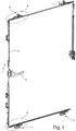
- FIG. 1 shows a displacement assembly 1 with a designed as a rotating espagnolette fitting actuating mechanism 2, which can be actuated via an actuating handle 3.
- the actuating mechanism 2 is mounted on a wing of a window or door, not shown here, and extends along the fold circumferential direction.
- the displacement arrangement has four points 4 - 7, at which a guide part is displaceable transversely to the fold circumferential direction with respect to a wing or with respect to the actuating mechanism 2.
- the guide member 8 is shown without between the guide part 8 and the actuating mechanism 2 arranged wing attachment part.
- the actuating mechanism 2 has a control projection 9 designed as a control element, which can engage in a control contour 10, designed as a control contour, in particular control slot, of the guide part 8.
- the control slot is aligned obliquely to the Falz donorsscardi 11.
- the guide part 8 of FIG. 2 has a running roller assembly 12, which will be described in more detail below.
- a roller 13 can be seen, which is rotatable about a perpendicular to the Falz donorsscardi 11 and parallel to the main plane of a door or a window oriented axis of rotation.
- the roller 13 has a diameter which is greater than the width of the carriage assembly 12.
- the FIG. 3 shows a representation of the detail B of FIG. 1 in an exploded view.
- the guide member 15 also has a roller 16 which is rotatably disposed about a vertical axis of rotation. The axis of rotation of the roller 16 is thus aligned perpendicular to the Falz donorss512 11 and parallel to the main plane.
- the roller 16 is intended to cooperate with a fixed enclosure.
- the guide member 15 has no carriage assembly.
- a control element 17, which is designed as a control projection is provided and arranged on the actuating mechanism 2.
- the control projection may be formed as a roller, which is arranged on a drive rod.
- the control element 17 engages through a wing attachment part 18, on which the guide element 15 is arranged to be displaceable transversely to the fold circumferential direction 11.
- the control element 17 engages in a control element 10 of the guide element 15.
- the wing attachment part 18 has transverse guides 19, 20, along which the guide part 15 is displaceable relative to the wing attachment part 18. Furthermore, it can be seen that the wing attachment part 18, the guide member 15 in the areas 21, 22 overlaps. As a result, the guide part 15 is held on the wing attachment part 18.
- FIG. 5 shows the guide member 8 in one of FIG. 4 corresponding representation.
- the arrangement of FIG. 5 corresponds to the arrangement of Figure 4 with the exception that on the guide member 8, a roller assembly 12 is arranged.
- the roller assembly 12 has two rollers 25, 26 which are rotatably mounted on a roller holder 27.
- the roller holder 27 in turn is connected via a rotation axis 28 pivotally connected to the guide member 8.
- This means that the roller assembly 12 is arranged pivotally limited about the pivot axis 28.
- unevenness of a running rail or curvatures of a wing spar can be compensated.
- the roller assembly 12 In a direction parallel to the pivot axis 28, the roller assembly 12 is mounted with little play, in particular in the range of 5/10 - 8/10 mm.
- a slight adjustment of the roller assembly 12 transverse to the guide member 8 is possible.
- loads on the rollers 25, 26 are kept low.
- the diameter of the roller 13 is greater than the width of the roller assembly 12th
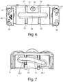
- the FIG. 6 shows a wing attachment part 18, which in both the arrangement according to the FIG. 5 as well as in the arrangement according to the FIG. 4 can be used.
- the wing attachment part 18 has a rectilinear longitudinal slot 30 through which the control element 9 or 17 can project in order to engage the control element 10.
- the transverse guides 19, 20 are also visible.
- the transverse guides 31, 32 are designed such that a region 33 results between them, which is dovetail-shaped in cross-section.
- the region 33 in turn provides a transverse guide for the guide parts 8, 15 Due to the dovetail-shaped configuration, tilting of the guide parts 8, 15 relative to the wing attachment part 18 can be prevented.
- a fastening opening 34 is provided in the region of the transverse guide 33. Through the mounting hole 34, a screw can be screwed into the sash. Further attachment openings 35 - 38 can also be seen.
- FIG. 7 shows a view of the guide member 8.
- the control element 10 has two sections 10.1, 10.2, which are aligned differently from the Falz donors.
- the section 10.1 has a larger angle to the fold circumferential direction or longitudinal direction of the wing part 8 than the section 10.2.
- the transverse guide 33 of the wing attachment part 18 is guided in the region 35 of the guide part 8.
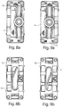
- FIG. 8a shows a view from below of the guide member 8 and the wing attachment portion 18.
- the guide member 8 is in a right extreme position corresponding to a closed position of the wing.
- the view of the wing attachment part 18 according to the FIG. 8b shows that the control 9 is located in section 10.2 of the control 10.
- the control 9 is shifted in Falz donorsscardi, so according to the FIG. 8b displaced upward, the control element 9 enters the area 10.1 of the control element 10, as shown in Figure 9b.
- This causes the guide member 8 is displaced to the left, as in the FIG. 9a you can see.
- This position corresponds to a sliding position, this means that a wing can be moved in this position relative to the fixed enclosure.
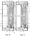
- FIG. 10 shows a view from the closure side of a window, a door or the like.
- the operating mechanism 2 is mounted on a wing 50. This is supported via the roller assembly 12 on a running rail 51, which is part of a bump 52. Between the wing 50 and a fixed frame 53, which is also like the bottom sill 52 part of a solid enclosure, a gap 54 can be seen. Accordingly, the wing 50 does not abut against a circumferential seal 55 which is arranged on the fixed frame 53. The roller 13 abuts against a trained as a vertical web guide 56 of the fixed enclosure. In the position shown, the wing 50 can be moved with respect to the fixed frame 53, wherein the roller 13 can be supported on the guide 56 or roll on this.
- a guide 57 is also provided on the fixed border, which is here formed like a groove.
- a roller 16 is guided, which is part of a guide member 15.
Landscapes
- Engineering & Computer Science (AREA)
- Mechanical Engineering (AREA)
- Civil Engineering (AREA)
- Structural Engineering (AREA)
- Operating, Guiding And Securing Of Roll- Type Closing Members (AREA)
- Power-Operated Mechanisms For Wings (AREA)
- Support Devices For Sliding Doors (AREA)
- Specific Sealing Or Ventilating Devices For Doors And Windows (AREA)
- Eye Examination Apparatus (AREA)
Priority Applications (9)
| Application Number | Priority Date | Filing Date | Title |
|---|---|---|---|
| ES13177345.9T ES2624434T3 (es) | 2013-07-22 | 2013-07-22 | Bisagra para el montaje de una hoja corredera en un bastidor fijo |
| HUE13177345A HUE032513T2 (en) | 2013-07-22 | 2013-07-22 | Attachment to press a sliding wing to a fixed frame |
| PL13177345T PL2829679T3 (pl) | 2013-07-22 | 2013-07-22 | Okucie do dociskania skrzydła przesuwnego do stałego obramowania |
| DK13177345.9T DK2829679T3 (da) | 2013-07-22 | 2013-07-22 | Beslag til at presse en skyderamme mod en fast indfatning |
| EP13177345.9A EP2829679B1 (de) | 2013-07-22 | 2013-07-22 | Beschlag zum Anpressen eines Schiebeflügels an eine feste Einfassung |
| CN201480041298.9A CN105492713B (zh) | 2013-07-22 | 2014-07-11 | 用于将滑动翼扇压紧到固定围框上的配件 |
| PCT/EP2014/064911 WO2015010925A1 (de) | 2013-07-22 | 2014-07-11 | Beschlag zum anpressen eines schiebeflügels an eine feste einfassung |
| KR1020167000758A KR102004595B1 (ko) | 2013-07-22 | 2014-07-11 | 고정 문틀 상에 슬라이딩 문짝을 압착하기 위한 기구 |
| US14/898,238 US10077594B2 (en) | 2013-07-22 | 2014-07-11 | Fitting for pressing a sliding wing onto a fixed enclosure |
Applications Claiming Priority (1)
| Application Number | Priority Date | Filing Date | Title |
|---|---|---|---|
| EP13177345.9A EP2829679B1 (de) | 2013-07-22 | 2013-07-22 | Beschlag zum Anpressen eines Schiebeflügels an eine feste Einfassung |
Publications (2)
| Publication Number | Publication Date |
|---|---|
| EP2829679A1 EP2829679A1 (de) | 2015-01-28 |
| EP2829679B1 true EP2829679B1 (de) | 2017-02-01 |
Family
ID=48856504
Family Applications (1)
| Application Number | Title | Priority Date | Filing Date |
|---|---|---|---|
| EP13177345.9A Active EP2829679B1 (de) | 2013-07-22 | 2013-07-22 | Beschlag zum Anpressen eines Schiebeflügels an eine feste Einfassung |
Country Status (9)
| Country | Link |
|---|---|
| US (1) | US10077594B2 (da) |
| EP (1) | EP2829679B1 (da) |
| KR (1) | KR102004595B1 (da) |
| CN (1) | CN105492713B (da) |
| DK (1) | DK2829679T3 (da) |
| ES (1) | ES2624434T3 (da) |
| HU (1) | HUE032513T2 (da) |
| PL (1) | PL2829679T3 (da) |
| WO (1) | WO2015010925A1 (da) |
Cited By (8)
| Publication number | Priority date | Publication date | Assignee | Title |
|---|---|---|---|---|
| NO20190998A1 (en) * | 2019-08-19 | 2021-02-22 | Nordan As | Fittings for sliding doors or windows. |
| DE102021201885A1 (de) | 2021-02-26 | 2022-09-01 | Roto Frank Fenster- und Türtechnologie GmbH | Andruckeinrichtung für ein Fenster oder eine Tür |
| DE102021214993A1 (de) | 2021-12-23 | 2023-06-29 | Roto Frank Fenster- und Türtechnologie GmbH | Fenster oder Tür mit einer einen Flügel präzise kontrollierenden, aber flexibel einsetzbaren Abstellmechanik |
| DE102022204891A1 (de) | 2022-05-17 | 2023-11-23 | Roto Frank Fenster- und Türtechnologie GmbH | Barrierefreie Schiebetür mit einem Laufwagen für einen querabstellbaren Flügel |
| DE102022204890A1 (de) | 2022-05-17 | 2023-11-23 | Roto Frank Fenster- und Türtechnologie GmbH | Barrierefreie Schiebetür mit einem querabstellbaren Flügel |
| DE102022205298A1 (de) | 2022-05-25 | 2023-11-30 | Roto Frank Fenster- und Türtechnologie GmbH | Führungsrolle mit zweifachem Reibmantel |
| DE102023208073A1 (de) | 2023-08-23 | 2025-02-27 | Roto Frank Fenster- und Türtechnologie GmbH | Schiebetür mit schwenkbarer Dichtleiste |
| WO2025110958A1 (en) * | 2023-11-22 | 2025-05-30 | İleri̇ Pencere Kapi Si̇stemleri̇ Sanayi̇ Ve Ti̇caret Anoni̇m Şi̇rketi̇ | Sash centering mechanism |
Families Citing this family (22)
| Publication number | Priority date | Publication date | Assignee | Title |
|---|---|---|---|---|
| DE102014220837B3 (de) * | 2014-10-15 | 2016-01-14 | Roto Frank Ag | Laufwagen zum leichtgängigen Abstellen eines Schiebeflügels von einem festen Rahmen eines Fensters, einer Tür oder dergleichen |
| CN104863460B (zh) * | 2015-05-27 | 2017-03-15 | 广东坚朗五金制品股份有限公司 | 推拉门窗五金系统 |
| CN105909155B (zh) * | 2016-06-03 | 2018-06-26 | 孙朝霞 | 门窗系统 |
| DE102016225385A1 (de) * | 2016-12-19 | 2018-06-21 | Roto Frank Ag | Verlagerungsanordnung mit Wälzlagerführung |
| WO2019092290A1 (es) * | 2017-11-09 | 2019-05-16 | Lara Anaya Cristian | Sistema de cierre para puertas y ventanas correderas |
| US10718143B2 (en) * | 2018-02-27 | 2020-07-21 | Arconic Technologies Llc | Sliding door system |
| JP7083668B2 (ja) * | 2018-03-15 | 2022-06-13 | Ykk Ap株式会社 | 戸車、戸体及び建具 |
| DE102018111201A1 (de) | 2018-05-09 | 2019-11-14 | Roto Frank Ag | Beschlaganordnung für ein Schiebefenster oder eine Schiebetür |
| DE102018116417A1 (de) | 2018-07-06 | 2020-01-09 | Roto Frank Fenster- und Türtechnologie GmbH | Vormontierte Beschlaggruppe und Beschlaganordnung für ein Fenster oder eine Tür |
| US11585122B2 (en) * | 2018-12-19 | 2023-02-21 | Jeld-Wen, Inc. | Shoot bolt for limiting movement of a fenestration panel |
| NO20191445A1 (en) * | 2019-12-06 | 2021-04-26 | Wheel Me As | Releasable wheel element |
| CN216380945U (zh) | 2020-01-23 | 2022-04-26 | (株)顾客满足技术 | 具有换气功能及水平紧贴功能的门窗组装体 |
| DE102020210443A1 (de) * | 2020-08-17 | 2022-02-17 | Roto Frank Fenster- und Türtechnologie GmbH | Laufwagenanordnung mit wälzlagergeführter Kraftabtragung in Verschieberichtung sowie Fenster oder Tür mit einer solchen Laufwagenanordnung |
| DE102021201882A1 (de) * | 2021-02-26 | 2022-09-01 | Roto Frank Fenster- und Türtechnologie GmbH | Einfache Steuerzapfenbefestigung |
| KR102373584B1 (ko) | 2021-06-18 | 2022-03-11 | 주식회사 씨에스테크 | 환기 기능 및 수평 밀착 기능을 갖는 창호 조립체 및 이에 사용되는 걸림 안내부 |
| KR102344863B1 (ko) * | 2021-10-14 | 2021-12-30 | 주식회사 다우 | 슬라이딩 창호 수평밀착용 이동체 및 이를 구비한 창호시스템 |
| CN116025249A (zh) * | 2021-10-27 | 2023-04-28 | 李辉 | 电动推拉密封窗 |
| DE102022114632A1 (de) | 2022-06-10 | 2023-12-21 | Roto Frank Fenster- und Türtechnologie GmbH | Beschlaganordnung zur Anordnung zwischen einem festen Rahmen und einem Flügel eines Fensters oder einer Tür sowie Fenster oder Tür mit einer derartigen Beschlaganordnung |
| AT527101A1 (de) * | 2023-04-12 | 2024-10-15 | Blum Gmbh Julius | Anordnung aus einer Antriebsvorrichtung, einem Bauteil zum Verschließen einer Öffnung und einer Führungseinrichtung |
| DE102023210534A1 (de) | 2023-10-25 | 2025-04-30 | Aug. Winkhaus SE & Co. KG | Laufwagen zum Verschieben eines Flügels eines Fensters |
| KR102774369B1 (ko) | 2024-10-07 | 2025-03-05 | 주식회사 제이제이시스템 | 미닫이창호의 횡방향 밀봉시스템 |
| KR102831270B1 (ko) | 2025-04-08 | 2025-07-08 | 주식회사 씨에스테크 | 수평 이동형 창호용 수평 이동 모듈 |
Family Cites Families (22)
| Publication number | Priority date | Publication date | Assignee | Title |
|---|---|---|---|---|
| US3056176A (en) * | 1959-12-23 | 1962-10-02 | American Seal Kap Corp | Wall and sliding door structure |
| US3660936A (en) * | 1970-12-07 | 1972-05-09 | David W Bryson | Window construction |
| FR2294312A1 (fr) * | 1974-12-12 | 1976-07-09 | Simonin Claude | Fenetre a vantail coulissant |
| JPS5926751B2 (ja) * | 1979-08-16 | 1984-06-30 | ワイケイケイ株式会社 | サッシの気密装置 |
| JPS60155882U (ja) * | 1984-03-26 | 1985-10-17 | 木下 日雄 | 冷蔵庫の自動扉 |
| US5012611A (en) * | 1990-07-19 | 1991-05-07 | Lava Group Inc. | Sealing mechanism for a window set |
| US5542213A (en) * | 1994-10-27 | 1996-08-06 | Freeman Marine Equipment, Inc. | Sliding marine closure |
| US5836111A (en) * | 1996-04-16 | 1998-11-17 | Fine Industries, Inc. | Opening-closing device for windows |
| US6135511A (en) * | 1996-11-01 | 2000-10-24 | Newell Operating Company | Window locking system |
| US6497072B2 (en) * | 1997-01-10 | 2002-12-24 | Frip Ab | Sliding panel for longitudinal and lateral movement in a frame structure |
| NL1009220C2 (nl) * | 1998-05-20 | 1999-11-24 | Johannes Maria Musters | Samenstel voorzien van een een opening begrenzend kozijn en een ten opzichte van het kozijn in de openingsrichting verschuifbaar paneel. |
| US7708322B2 (en) * | 2001-05-30 | 2010-05-04 | Caldwell Manufacturing Company | Actuator for use in fenestration systems |
| EP1862625B1 (en) * | 2005-03-23 | 2012-07-04 | Sugatsune Kogyo Co., Ltd. | Device for guiding plate-like object |
| KR100721455B1 (ko) | 2005-12-21 | 2007-05-23 | 주식회사 엘지화학 | 시스템창호 개폐장치 |
| KR100729222B1 (ko) | 2005-12-29 | 2007-06-19 | 이광석 | 미서기 창호 시스템의 개폐장치 및 개폐방법 |
| JP2007303109A (ja) * | 2006-05-10 | 2007-11-22 | Bs Door Kk | 懸垂引戸式ドアの開閉機構 |
| KR100963437B1 (ko) * | 2008-01-29 | 2010-06-17 | 한화엘앤씨 주식회사 | 고하중 창호용 롤러 |
| KR101202093B1 (ko) * | 2010-05-11 | 2012-11-15 | (주)엘지하우시스 | 수평 밀착 창호의 잠금모듈 |
| WO2012011099A1 (en) * | 2010-07-19 | 2012-01-26 | Hardoor Top Design & Technology Ltd | System of ejecting a sliding door |
| KR101280118B1 (ko) * | 2010-10-27 | 2013-07-05 | (주)엘지하우시스 | 수평밀착창호 |
| KR101254327B1 (ko) * | 2012-10-24 | 2013-04-12 | (주)코리아쇼와록 | 수평밀착창호의 잠금모듈 |
| US20160130847A1 (en) * | 2014-11-12 | 2016-05-12 | Truth Hardware Corporation | Around-the-corner multi-point window lock mechanism for casement and awning windows |
-
2013
- 2013-07-22 EP EP13177345.9A patent/EP2829679B1/de active Active
- 2013-07-22 HU HUE13177345A patent/HUE032513T2/en unknown
- 2013-07-22 DK DK13177345.9T patent/DK2829679T3/da active
- 2013-07-22 PL PL13177345T patent/PL2829679T3/pl unknown
- 2013-07-22 ES ES13177345.9T patent/ES2624434T3/es active Active
-
2014
- 2014-07-11 US US14/898,238 patent/US10077594B2/en active Active
- 2014-07-11 WO PCT/EP2014/064911 patent/WO2015010925A1/de not_active Ceased
- 2014-07-11 KR KR1020167000758A patent/KR102004595B1/ko active Active
- 2014-07-11 CN CN201480041298.9A patent/CN105492713B/zh active Active
Cited By (14)
| Publication number | Priority date | Publication date | Assignee | Title |
|---|---|---|---|---|
| NO20190998A1 (en) * | 2019-08-19 | 2021-02-22 | Nordan As | Fittings for sliding doors or windows. |
| NO346023B1 (en) * | 2019-08-19 | 2021-12-27 | Nordan As | Fittings for sliding doors or windows. |
| DE102021201885A1 (de) | 2021-02-26 | 2022-09-01 | Roto Frank Fenster- und Türtechnologie GmbH | Andruckeinrichtung für ein Fenster oder eine Tür |
| DE102021214993A1 (de) | 2021-12-23 | 2023-06-29 | Roto Frank Fenster- und Türtechnologie GmbH | Fenster oder Tür mit einer einen Flügel präzise kontrollierenden, aber flexibel einsetzbaren Abstellmechanik |
| WO2023118177A1 (de) | 2021-12-23 | 2023-06-29 | Roto Frank Fenster- und Türtechnologie GmbH | Fenster oder tür mit einer einen flügel präzise kontrollierenden, aber flexibel einsetzbaren abstellmechanik |
| US12486703B2 (en) | 2021-12-23 | 2025-12-02 | Roto Frank Fenster—und Tuertechnologie GmbH | Window or door with a precisely controlling, but flexibly usable, sash stop mechanism |
| DE102022204890A1 (de) | 2022-05-17 | 2023-11-23 | Roto Frank Fenster- und Türtechnologie GmbH | Barrierefreie Schiebetür mit einem querabstellbaren Flügel |
| WO2023222380A1 (de) | 2022-05-17 | 2023-11-23 | Roto Frank Fenster- und Türtechnologie GmbH | Barrierefreie schiebetür mit einem laufwagen für einen querabstellbaren flügel |
| WO2023222379A1 (de) | 2022-05-17 | 2023-11-23 | Roto Frank Fenster- und Türtechnologie GmbH | Barrierefreie schiebetür mit einem querabstellbaren flügel |
| DE102022204891A1 (de) | 2022-05-17 | 2023-11-23 | Roto Frank Fenster- und Türtechnologie GmbH | Barrierefreie Schiebetür mit einem Laufwagen für einen querabstellbaren Flügel |
| DE102022205298A1 (de) | 2022-05-25 | 2023-11-30 | Roto Frank Fenster- und Türtechnologie GmbH | Führungsrolle mit zweifachem Reibmantel |
| DE102023208073A1 (de) | 2023-08-23 | 2025-02-27 | Roto Frank Fenster- und Türtechnologie GmbH | Schiebetür mit schwenkbarer Dichtleiste |
| WO2025040475A1 (de) | 2023-08-23 | 2025-02-27 | Roto Frank Fenster- und Türtechnologie GmbH | Schiebetür mit schwenkbarer dichtleiste |
| WO2025110958A1 (en) * | 2023-11-22 | 2025-05-30 | İleri̇ Pencere Kapi Si̇stemleri̇ Sanayi̇ Ve Ti̇caret Anoni̇m Şi̇rketi̇ | Sash centering mechanism |
Also Published As
| Publication number | Publication date |
|---|---|
| WO2015010925A1 (de) | 2015-01-29 |
| ES2624434T3 (es) | 2017-07-14 |
| EP2829679A1 (de) | 2015-01-28 |
| KR20160033690A (ko) | 2016-03-28 |
| US20160145932A1 (en) | 2016-05-26 |
| US10077594B2 (en) | 2018-09-18 |
| CN105492713B (zh) | 2017-07-07 |
| PL2829679T3 (pl) | 2017-09-29 |
| DK2829679T3 (da) | 2017-04-24 |
| CN105492713A (zh) | 2016-04-13 |
| KR102004595B1 (ko) | 2019-07-26 |
| HUE032513T2 (en) | 2017-09-28 |
Similar Documents
| Publication | Publication Date | Title |
|---|---|---|
| EP2829679B1 (de) | Beschlag zum Anpressen eines Schiebeflügels an eine feste Einfassung | |
| EP3818228A1 (de) | Vormontierte beschlaggruppe und beschlaganordnung für ein fenster oder eine tür | |
| EP4473182B1 (de) | Profilanordnung eines fensters oder einer tür mit einem flügelprofil, insbesondere einem schiebeflügelprofil | |
| EP2682545B1 (de) | Verschlussanordnung für eine Schiebetür oder ein Schiebefenster, und Schiebetür oder Schiebefenster | |
| EP1816295B1 (de) | Insektenschutztür | |
| EP2871312B1 (de) | Spaltlüftungsanordnung für eine Schiebetür oder -fenster und Schiebetür oder -fenster | |
| EP3060736A1 (de) | Beschlag für fenster, türen oder dergleichen | |
| DE3617216C2 (da) | ||
| EP4146888B1 (de) | Scharnierbaugruppe mit gemeinsamer betätigung | |
| DE102012213786B3 (de) | Verlagerungsanordnung zur Verlagerung eines Flügels eines Fensters, einer Tür oder dergleichen relativ zu einer festen Einfassung | |
| EP1614844A2 (de) | Drehlagervorrichtung | |
| DE2116144A1 (de) | Verschluß- und/oder Riegel vorrichtung an Treibstangenbeschlägen für Fenster, Türen od. dgl | |
| EP1425489B1 (de) | Drehkippbeschlag | |
| EP1231345B1 (de) | Gesteuerte Verriegelungsvorrichtung und Eckumlenkung | |
| DE102012106191B4 (de) | Vorspannbauteil für eine Fenster- oder Türvorrichtung und Fenster- oder Türvorrichtung | |
| EP4421285B1 (de) | Schiebetür mit einem verriegelbaren schiebeflügel | |
| EP2690241B1 (de) | Beschlag für eine parallel abstellbare Schiebetür oder ein parallel abstellbares Schiebefenster | |
| EP0429981B1 (de) | Verdeckt im Falz angeordneter Beschlag für Kipp-Schwenk-flügelfenster oder -türen, insb. mit Holzrahmen | |
| EP0280950B1 (de) | Beschlag für ein Fenster, eine Tür od. dgl. | |
| DE3215452A1 (de) | Eckumlenkung fuer treibstangenbeschlaege von fenstern, tueren od. dgl. | |
| DE3905995C2 (da) | ||
| EP1659241B1 (de) | Beschlag zur Einbruchsicherung für ein mehrflügeliges Fenster oder Tür | |
| EP3444417B1 (de) | Ladensystem für gebäudeöffnungen | |
| EP0672811A1 (de) | Fehlbedienungssperre für das Betätigungsgestänge eines Fensters, einer Tür od. dgl. | |
| DE29501564U1 (de) | Kipptor für Lackier- und/oder Trockenkabinen |
Legal Events
| Date | Code | Title | Description |
|---|---|---|---|
| 17P | Request for examination filed |
Effective date: 20130722 |
|
| AK | Designated contracting states |
Kind code of ref document: A1 Designated state(s): AL AT BE BG CH CY CZ DE DK EE ES FI FR GB GR HR HU IE IS IT LI LT LU LV MC MK MT NL NO PL PT RO RS SE SI SK SM TR |
|
| AX | Request for extension of the european patent |
Extension state: BA ME |
|
| PUAI | Public reference made under article 153(3) epc to a published international application that has entered the european phase |
Free format text: ORIGINAL CODE: 0009012 |
|
| R17P | Request for examination filed (corrected) |
Effective date: 20150708 |
|
| RBV | Designated contracting states (corrected) |
Designated state(s): AL AT BE BG CH CY CZ DE DK EE ES FI FR GB GR HR HU IE IS IT LI LT LU LV MC MK MT NL NO PL PT RO RS SE SI SK SM TR |
|
| 17Q | First examination report despatched |
Effective date: 20151030 |
|
| GRAP | Despatch of communication of intention to grant a patent |
Free format text: ORIGINAL CODE: EPIDOSNIGR1 |
|
| INTG | Intention to grant announced |
Effective date: 20160405 |
|
| GRAS | Grant fee paid |
Free format text: ORIGINAL CODE: EPIDOSNIGR3 |
|
| GRAA | (expected) grant |
Free format text: ORIGINAL CODE: 0009210 |
|
| AK | Designated contracting states |
Kind code of ref document: B1 Designated state(s): AL AT BE BG CH CY CZ DE DK EE ES FI FR GB GR HR HU IE IS IT LI LT LU LV MC MK MT NL NO PL PT RO RS SE SI SK SM TR |
|
| REG | Reference to a national code |
Ref country code: GB Ref legal event code: FG4D Free format text: NOT ENGLISH |
|
| REG | Reference to a national code |
Ref country code: AT Ref legal event code: REF Ref document number: 865756 Country of ref document: AT Kind code of ref document: T Effective date: 20170215 Ref country code: CH Ref legal event code: EP |
|
| REG | Reference to a national code |
Ref country code: IE Ref legal event code: FG4D Free format text: LANGUAGE OF EP DOCUMENT: GERMAN |
|
| REG | Reference to a national code |
Ref country code: DE Ref legal event code: R096 Ref document number: 502013006216 Country of ref document: DE |
|
| REG | Reference to a national code |
Ref country code: NL Ref legal event code: FP |
|
| REG | Reference to a national code |
Ref country code: DK Ref legal event code: T3 Effective date: 20170419 |
|
| REG | Reference to a national code |
Ref country code: SE Ref legal event code: TRGR |
|
| REG | Reference to a national code |
Ref country code: RO Ref legal event code: EPE |
|
| REG | Reference to a national code |
Ref country code: NO Ref legal event code: T2 Effective date: 20170201 |
|
| REG | Reference to a national code |
Ref country code: LT Ref legal event code: MG4D |
|
| REG | Reference to a national code |
Ref country code: ES Ref legal event code: FG2A Ref document number: 2624434 Country of ref document: ES Kind code of ref document: T3 Effective date: 20170714 |
|
| REG | Reference to a national code |
Ref country code: FR Ref legal event code: PLFP Year of fee payment: 5 |
|
| PG25 | Lapsed in a contracting state [announced via postgrant information from national office to epo] |
Ref country code: HR Free format text: LAPSE BECAUSE OF FAILURE TO SUBMIT A TRANSLATION OF THE DESCRIPTION OR TO PAY THE FEE WITHIN THE PRESCRIBED TIME-LIMIT Effective date: 20170201 Ref country code: IS Free format text: LAPSE BECAUSE OF FAILURE TO SUBMIT A TRANSLATION OF THE DESCRIPTION OR TO PAY THE FEE WITHIN THE PRESCRIBED TIME-LIMIT Effective date: 20170601 Ref country code: GR Free format text: LAPSE BECAUSE OF FAILURE TO SUBMIT A TRANSLATION OF THE DESCRIPTION OR TO PAY THE FEE WITHIN THE PRESCRIBED TIME-LIMIT Effective date: 20170502 Ref country code: FI Free format text: LAPSE BECAUSE OF FAILURE TO SUBMIT A TRANSLATION OF THE DESCRIPTION OR TO PAY THE FEE WITHIN THE PRESCRIBED TIME-LIMIT Effective date: 20170201 Ref country code: LT Free format text: LAPSE BECAUSE OF FAILURE TO SUBMIT A TRANSLATION OF THE DESCRIPTION OR TO PAY THE FEE WITHIN THE PRESCRIBED TIME-LIMIT Effective date: 20170201 |
|
| PG25 | Lapsed in a contracting state [announced via postgrant information from national office to epo] |
Ref country code: PT Free format text: LAPSE BECAUSE OF FAILURE TO SUBMIT A TRANSLATION OF THE DESCRIPTION OR TO PAY THE FEE WITHIN THE PRESCRIBED TIME-LIMIT Effective date: 20170601 Ref country code: LV Free format text: LAPSE BECAUSE OF FAILURE TO SUBMIT A TRANSLATION OF THE DESCRIPTION OR TO PAY THE FEE WITHIN THE PRESCRIBED TIME-LIMIT Effective date: 20170201 Ref country code: RS Free format text: LAPSE BECAUSE OF FAILURE TO SUBMIT A TRANSLATION OF THE DESCRIPTION OR TO PAY THE FEE WITHIN THE PRESCRIBED TIME-LIMIT Effective date: 20170201 Ref country code: BG Free format text: LAPSE BECAUSE OF FAILURE TO SUBMIT A TRANSLATION OF THE DESCRIPTION OR TO PAY THE FEE WITHIN THE PRESCRIBED TIME-LIMIT Effective date: 20170501 |
|
| REG | Reference to a national code |
Ref country code: HU Ref legal event code: AG4A Ref document number: E032513 Country of ref document: HU |
|
| PG25 | Lapsed in a contracting state [announced via postgrant information from national office to epo] |
Ref country code: CZ Free format text: LAPSE BECAUSE OF FAILURE TO SUBMIT A TRANSLATION OF THE DESCRIPTION OR TO PAY THE FEE WITHIN THE PRESCRIBED TIME-LIMIT Effective date: 20170201 Ref country code: EE Free format text: LAPSE BECAUSE OF FAILURE TO SUBMIT A TRANSLATION OF THE DESCRIPTION OR TO PAY THE FEE WITHIN THE PRESCRIBED TIME-LIMIT Effective date: 20170201 Ref country code: SK Free format text: LAPSE BECAUSE OF FAILURE TO SUBMIT A TRANSLATION OF THE DESCRIPTION OR TO PAY THE FEE WITHIN THE PRESCRIBED TIME-LIMIT Effective date: 20170201 |
|
| PGFP | Annual fee paid to national office [announced via postgrant information from national office to epo] |
Ref country code: CH Payment date: 20170724 Year of fee payment: 5 Ref country code: RO Payment date: 20170714 Year of fee payment: 5 |
|
| REG | Reference to a national code |
Ref country code: DE Ref legal event code: R097 Ref document number: 502013006216 Country of ref document: DE |
|
| PG25 | Lapsed in a contracting state [announced via postgrant information from national office to epo] |
Ref country code: SM Free format text: LAPSE BECAUSE OF FAILURE TO SUBMIT A TRANSLATION OF THE DESCRIPTION OR TO PAY THE FEE WITHIN THE PRESCRIBED TIME-LIMIT Effective date: 20170201 |
|
| PGFP | Annual fee paid to national office [announced via postgrant information from national office to epo] |
Ref country code: HU Payment date: 20170713 Year of fee payment: 5 |
|
| PLBE | No opposition filed within time limit |
Free format text: ORIGINAL CODE: 0009261 |
|
| STAA | Information on the status of an ep patent application or granted ep patent |
Free format text: STATUS: NO OPPOSITION FILED WITHIN TIME LIMIT |
|
| 26N | No opposition filed |
Effective date: 20171103 |
|
| PG25 | Lapsed in a contracting state [announced via postgrant information from national office to epo] |
Ref country code: SI Free format text: LAPSE BECAUSE OF FAILURE TO SUBMIT A TRANSLATION OF THE DESCRIPTION OR TO PAY THE FEE WITHIN THE PRESCRIBED TIME-LIMIT Effective date: 20170201 |
|
| REG | Reference to a national code |
Ref country code: IE Ref legal event code: MM4A |
|
| PG25 | Lapsed in a contracting state [announced via postgrant information from national office to epo] |
Ref country code: IE Free format text: LAPSE BECAUSE OF NON-PAYMENT OF DUE FEES Effective date: 20170722 |
|
| PG25 | Lapsed in a contracting state [announced via postgrant information from national office to epo] |
Ref country code: LU Free format text: LAPSE BECAUSE OF NON-PAYMENT OF DUE FEES Effective date: 20170722 |
|
| REG | Reference to a national code |
Ref country code: FR Ref legal event code: PLFP Year of fee payment: 6 |
|
| PG25 | Lapsed in a contracting state [announced via postgrant information from national office to epo] |
Ref country code: MT Free format text: LAPSE BECAUSE OF FAILURE TO SUBMIT A TRANSLATION OF THE DESCRIPTION OR TO PAY THE FEE WITHIN THE PRESCRIBED TIME-LIMIT Effective date: 20170201 |
|
| REG | Reference to a national code |
Ref country code: CH Ref legal event code: PL |
|
| PG25 | Lapsed in a contracting state [announced via postgrant information from national office to epo] |
Ref country code: LI Free format text: LAPSE BECAUSE OF NON-PAYMENT OF DUE FEES Effective date: 20180731 Ref country code: HU Free format text: LAPSE BECAUSE OF NON-PAYMENT OF DUE FEES Effective date: 20180723 Ref country code: CH Free format text: LAPSE BECAUSE OF NON-PAYMENT OF DUE FEES Effective date: 20180731 |
|
| PG25 | Lapsed in a contracting state [announced via postgrant information from national office to epo] |
Ref country code: MC Free format text: LAPSE BECAUSE OF FAILURE TO SUBMIT A TRANSLATION OF THE DESCRIPTION OR TO PAY THE FEE WITHIN THE PRESCRIBED TIME-LIMIT Effective date: 20170201 |
|
| PG25 | Lapsed in a contracting state [announced via postgrant information from national office to epo] |
Ref country code: CY Free format text: LAPSE BECAUSE OF FAILURE TO SUBMIT A TRANSLATION OF THE DESCRIPTION OR TO PAY THE FEE WITHIN THE PRESCRIBED TIME-LIMIT Effective date: 20170201 |
|
| PG25 | Lapsed in a contracting state [announced via postgrant information from national office to epo] |
Ref country code: MK Free format text: LAPSE BECAUSE OF FAILURE TO SUBMIT A TRANSLATION OF THE DESCRIPTION OR TO PAY THE FEE WITHIN THE PRESCRIBED TIME-LIMIT Effective date: 20170201 |
|
| PG25 | Lapsed in a contracting state [announced via postgrant information from national office to epo] |
Ref country code: RO Free format text: LAPSE BECAUSE OF NON-PAYMENT OF DUE FEES Effective date: 20180722 |
|
| PG25 | Lapsed in a contracting state [announced via postgrant information from national office to epo] |
Ref country code: AL Free format text: LAPSE BECAUSE OF FAILURE TO SUBMIT A TRANSLATION OF THE DESCRIPTION OR TO PAY THE FEE WITHIN THE PRESCRIBED TIME-LIMIT Effective date: 20170201 |
|
| REG | Reference to a national code |
Ref country code: DE Ref legal event code: R081 Ref document number: 502013006216 Country of ref document: DE Owner name: ROTO FRANK FENSTER- UND TUERTECHNOLOGIE GMBH, DE Free format text: FORMER OWNER: ROTO FRANK AG, 70771 LEINFELDEN-ECHTERDINGEN, DE |
|
| PGFP | Annual fee paid to national office [announced via postgrant information from national office to epo] |
Ref country code: NL Payment date: 20250723 Year of fee payment: 13 |
|
| PGFP | Annual fee paid to national office [announced via postgrant information from national office to epo] |
Ref country code: ES Payment date: 20250819 Year of fee payment: 13 |
|
| PGFP | Annual fee paid to national office [announced via postgrant information from national office to epo] |
Ref country code: DK Payment date: 20250723 Year of fee payment: 13 Ref country code: DE Payment date: 20250722 Year of fee payment: 13 |
|
| PGFP | Annual fee paid to national office [announced via postgrant information from national office to epo] |
Ref country code: NO Payment date: 20250722 Year of fee payment: 13 |
|
| PGFP | Annual fee paid to national office [announced via postgrant information from national office to epo] |
Ref country code: PL Payment date: 20250710 Year of fee payment: 13 Ref country code: TR Payment date: 20250717 Year of fee payment: 13 Ref country code: IT Payment date: 20250731 Year of fee payment: 13 |
|
| PGFP | Annual fee paid to national office [announced via postgrant information from national office to epo] |
Ref country code: BE Payment date: 20250722 Year of fee payment: 13 Ref country code: GB Payment date: 20250724 Year of fee payment: 13 |
|
| PGFP | Annual fee paid to national office [announced via postgrant information from national office to epo] |
Ref country code: FR Payment date: 20250723 Year of fee payment: 13 Ref country code: AT Payment date: 20250721 Year of fee payment: 13 |
|
| PGFP | Annual fee paid to national office [announced via postgrant information from national office to epo] |
Ref country code: SE Payment date: 20250723 Year of fee payment: 13 |