EP2829679A1 - Beschlag zum Anpressen eines Schiebeflügels an eine feste Einfassung - Google Patents
Beschlag zum Anpressen eines Schiebeflügels an eine feste Einfassung Download PDFInfo
- Publication number
- EP2829679A1 EP2829679A1 EP13177345.9A EP13177345A EP2829679A1 EP 2829679 A1 EP2829679 A1 EP 2829679A1 EP 13177345 A EP13177345 A EP 13177345A EP 2829679 A1 EP2829679 A1 EP 2829679A1
- Authority
- EP
- European Patent Office
- Prior art keywords
- wing
- guide
- window
- door
- arrangement according
- Prior art date
- Legal status (The legal status is an assumption and is not a legal conclusion. Google has not performed a legal analysis and makes no representation as to the accuracy of the status listed.)
- Granted
Links
Images


Classifications
-
- E—FIXED CONSTRUCTIONS
- E06—DOORS, WINDOWS, SHUTTERS, OR ROLLER BLINDS IN GENERAL; LADDERS
- E06B—FIXED OR MOVABLE CLOSURES FOR OPENINGS IN BUILDINGS, VEHICLES, FENCES OR LIKE ENCLOSURES IN GENERAL, e.g. DOORS, WINDOWS, BLINDS, GATES
- E06B3/00—Window sashes, door leaves, or like elements for closing wall or like openings; Layout of fixed or moving closures, e.g. windows in wall or like openings; Features of rigidly-mounted outer frames relating to the mounting of wing frames
- E06B3/32—Arrangements of wings characterised by the manner of movement; Arrangements of movable wings in openings; Features of wings or frames relating solely to the manner of movement of the wing
- E06B3/34—Arrangements of wings characterised by the manner of movement; Arrangements of movable wings in openings; Features of wings or frames relating solely to the manner of movement of the wing with only one kind of movement
- E06B3/42—Sliding wings; Details of frames with respect to guiding
- E06B3/46—Horizontally-sliding wings
-
- E—FIXED CONSTRUCTIONS
- E05—LOCKS; KEYS; WINDOW OR DOOR FITTINGS; SAFES
- E05B—LOCKS; ACCESSORIES THEREFOR; HANDCUFFS
- E05B17/00—Accessories in connection with locks
- E05B17/0025—Devices for forcing the wing firmly against its seat or to initiate the opening of the wing
-
- E—FIXED CONSTRUCTIONS
- E05—LOCKS; KEYS; WINDOW OR DOOR FITTINGS; SAFES
- E05B—LOCKS; ACCESSORIES THEREFOR; HANDCUFFS
- E05B65/00—Locks or fastenings for special use
- E05B65/08—Locks or fastenings for special use for sliding wings
- E05B65/087—Locks or fastenings for special use for sliding wings the bolts sliding parallel to the wings
-
- E—FIXED CONSTRUCTIONS
- E05—LOCKS; KEYS; WINDOW OR DOOR FITTINGS; SAFES
- E05C—BOLTS OR FASTENING DEVICES FOR WINGS, SPECIALLY FOR DOORS OR WINDOWS
- E05C9/00—Arrangements of simultaneously actuated bolts or other securing devices at well-separated positions on the same wing
- E05C9/06—Arrangements of simultaneously actuated bolts or other securing devices at well-separated positions on the same wing with three or more sliding bars
- E05C9/063—Arrangements of simultaneously actuated bolts or other securing devices at well-separated positions on the same wing with three or more sliding bars extending along three or more sides of the wing or frame
-
- E—FIXED CONSTRUCTIONS
- E05—LOCKS; KEYS; WINDOW OR DOOR FITTINGS; SAFES
- E05D—HINGES OR SUSPENSION DEVICES FOR DOORS, WINDOWS OR WINGS
- E05D15/00—Suspension arrangements for wings
- E05D15/06—Suspension arrangements for wings for wings sliding horizontally more or less in their own plane
- E05D15/10—Suspension arrangements for wings for wings sliding horizontally more or less in their own plane movable out of one plane into a second parallel plane
-
- E—FIXED CONSTRUCTIONS
- E06—DOORS, WINDOWS, SHUTTERS, OR ROLLER BLINDS IN GENERAL; LADDERS
- E06B—FIXED OR MOVABLE CLOSURES FOR OPENINGS IN BUILDINGS, VEHICLES, FENCES OR LIKE ENCLOSURES IN GENERAL, e.g. DOORS, WINDOWS, BLINDS, GATES
- E06B1/00—Border constructions of openings in walls, floors, or ceilings; Frames to be rigidly mounted in such openings
- E06B1/04—Frames for doors, windows, or the like to be fixed in openings
-
- E—FIXED CONSTRUCTIONS
- E05—LOCKS; KEYS; WINDOW OR DOOR FITTINGS; SAFES
- E05D—HINGES OR SUSPENSION DEVICES FOR DOORS, WINDOWS OR WINGS
- E05D15/00—Suspension arrangements for wings
- E05D15/06—Suspension arrangements for wings for wings sliding horizontally more or less in their own plane
- E05D15/10—Suspension arrangements for wings for wings sliding horizontally more or less in their own plane movable out of one plane into a second parallel plane
- E05D2015/1026—Suspension arrangements for wings for wings sliding horizontally more or less in their own plane movable out of one plane into a second parallel plane accessories, e.g. sliding or rolling guides, latches
-
- E—FIXED CONSTRUCTIONS
- E05—LOCKS; KEYS; WINDOW OR DOOR FITTINGS; SAFES
- E05D—HINGES OR SUSPENSION DEVICES FOR DOORS, WINDOWS OR WINGS
- E05D15/00—Suspension arrangements for wings
- E05D15/06—Suspension arrangements for wings for wings sliding horizontally more or less in their own plane
- E05D15/10—Suspension arrangements for wings for wings sliding horizontally more or less in their own plane movable out of one plane into a second parallel plane
- E05D2015/1028—Suspension arrangements for wings for wings sliding horizontally more or less in their own plane movable out of one plane into a second parallel plane with only the wing moving transversely
- E05D2015/1039—Suspension arrangements for wings for wings sliding horizontally more or less in their own plane movable out of one plane into a second parallel plane with only the wing moving transversely the wing sliding transversely on the carriage
-
- E—FIXED CONSTRUCTIONS
- E05—LOCKS; KEYS; WINDOW OR DOOR FITTINGS; SAFES
- E05Y—INDEXING SCHEME ASSOCIATED WITH SUBCLASSES E05D AND E05F, RELATING TO CONSTRUCTION ELEMENTS, ELECTRIC CONTROL, POWER SUPPLY, POWER SIGNAL OR TRANSMISSION, USER INTERFACES, MOUNTING OR COUPLING, DETAILS, ACCESSORIES, AUXILIARY OPERATIONS NOT OTHERWISE PROVIDED FOR, APPLICATION THEREOF
- E05Y2201/00—Constructional elements; Accessories therefor
- E05Y2201/60—Suspension or transmission members; Accessories therefor
- E05Y2201/622—Suspension or transmission members elements
- E05Y2201/688—Rollers
- E05Y2201/692—Rollers having vertical axes
-
- E—FIXED CONSTRUCTIONS
- E05—LOCKS; KEYS; WINDOW OR DOOR FITTINGS; SAFES
- E05Y—INDEXING SCHEME ASSOCIATED WITH SUBCLASSES E05D AND E05F, RELATING TO CONSTRUCTION ELEMENTS, ELECTRIC CONTROL, POWER SUPPLY, POWER SIGNAL OR TRANSMISSION, USER INTERFACES, MOUNTING OR COUPLING, DETAILS, ACCESSORIES, AUXILIARY OPERATIONS NOT OTHERWISE PROVIDED FOR, APPLICATION THEREOF
- E05Y2600/00—Mounting or coupling arrangements for elements provided for in this subclass
- E05Y2600/50—Mounting methods; Positioning
- E05Y2600/56—Positioning, e.g. re-positioning, or pre-mounting
-
- E—FIXED CONSTRUCTIONS
- E05—LOCKS; KEYS; WINDOW OR DOOR FITTINGS; SAFES
- E05Y—INDEXING SCHEME ASSOCIATED WITH SUBCLASSES E05D AND E05F, RELATING TO CONSTRUCTION ELEMENTS, ELECTRIC CONTROL, POWER SUPPLY, POWER SIGNAL OR TRANSMISSION, USER INTERFACES, MOUNTING OR COUPLING, DETAILS, ACCESSORIES, AUXILIARY OPERATIONS NOT OTHERWISE PROVIDED FOR, APPLICATION THEREOF
- E05Y2800/00—Details, accessories and auxiliary operations not otherwise provided for
- E05Y2800/10—Additional functions
- E05Y2800/12—Sealing
-
- E—FIXED CONSTRUCTIONS
- E05—LOCKS; KEYS; WINDOW OR DOOR FITTINGS; SAFES
- E05Y—INDEXING SCHEME ASSOCIATED WITH SUBCLASSES E05D AND E05F, RELATING TO CONSTRUCTION ELEMENTS, ELECTRIC CONTROL, POWER SUPPLY, POWER SIGNAL OR TRANSMISSION, USER INTERFACES, MOUNTING OR COUPLING, DETAILS, ACCESSORIES, AUXILIARY OPERATIONS NOT OTHERWISE PROVIDED FOR, APPLICATION THEREOF
- E05Y2800/00—Details, accessories and auxiliary operations not otherwise provided for
- E05Y2800/74—Specific positions
- E05Y2800/742—Specific positions abnormal
Definitions
- the invention relates to a displacement arrangement for displacing a wing, in particular a sash, a window, a door or the like relative to a fixed enclosure of the window or the door in a direction transverse, in particular perpendicular, to the main plane of the window or the door, with an am Wing operable actuating mechanism which is movable at least with a portion in the circumferential direction Falz donorsscardi and a first control element which is arranged on the portion of the actuating mechanism, and a second control element which is arranged on a guide part which is intended to be guided on the fixed enclosure be arranged to be movable on the wing and transversely to the Falzparticularlysutter, wherein one of the controls as at least partially transverse to the Falzparticularlysplatz extending control contour and one of the controls is designed as a control projection cooperating with the control contour.
- Such a displacement arrangement is for example from the WO 2007/075075 A1 known.
- Sliding doors and sliding windows have the problem of sealing the sliding sash with respect to the fixed enclosure, in particular a fixed frame. If a seal between the fixed enclosure and the sliding leaf is arranged and the sliding leaf is not transversely displaceable to the main plane of the window or the door, it is very difficult to open the sliding leaf, as this is hindered by the arranged between the wing and fixed enclosure seal ,
- the WO 2007/075075 A1 by using a slanted slot in a drive rod and a bolt, which engages in the oblique slot and is arranged on a carriage to move a wing transversely to the wing main plane relative to a carriage.
- Object of the present invention is therefore to provide a structurally simple displacement arrangement which avoids the disadvantages mentioned above.
- a displacement arrangement for displacing a sash, in particular a sliding sash, a window, a door or the like relative to a fixed enclosure of the window or the door in a direction transversely, in particular perpendicular, to the main plane of the window or the door, with a wing-mounted actuating mechanism which is movable at least with a portion in the fold circumferential direction, and a first control element which is arranged on the portion of the actuating mechanism, and a second control element which is arranged on a guide part which is intended to be attached to the to be guided fixed edge and to be arranged transversely to the Falz prevalentsraum movable on the wing, wherein one of the controls as at least partially extending transversely to the Falzbiesraum control contour and one of the controls as cooperating with the control contour control projection is formed, wherein the guide member has a rotatable about a perpendicular to the Falz donorssraum and parallel to the main plane
- the guide member When the wing is displaced relative to the fixed enclosure parallel to the main plane of the window or door, the guide member must move relative to the fixed enclosure. If a rotatable roller is arranged on the guide part, the forces required for displacing the blade can be kept low and the wear on the guide part can be minimized since the roller can roll on the fixed border. In this case, the role in a groove-like guidance of the fixed enclosure or on a guide, in particular a guide bar, which is aligned parallel to the main plane of the window or the door, be guided. Upon actuation of the actuating mechanism, the control projection and moves the control contour relative to each other.
- the control contour may be formed, for example, as a curved or curved control slot.
- the control projection may be formed, for example, as a bolt which is arranged on a drive rod of a drive rod fitting, wherein the drive rod is part of the actuating mechanism. In principle, however, it is also conceivable, for example, to provide a control slot on a drive rod and accordingly to arrange a bolt on the guide part.
- the guide part can interact with a threshold. Therefore, a displacement of the guide member relative to the wing leads to a displacement of the wing transversely to the main plane of the window or the door. In this way, for example, a seal between wing and fixed enclosure can be clamped.
- the guide member is displaceable only transversely to the Falz donorss512 with respect to the wing.
- the guide member is preferably blocked in the fold circumferential direction on the wing, so that it can not move in Falz donorssraum relative to the wing.
- the guide member is guided on the wing. This results in a defined movement of the guide part relative to the wing. In addition, can be prevented by the guide that moves the guide member in Falz particularlysraum relative to the wing.
- the guide part can be arranged directly on the wing or arranged on a wing attachment part, which can be fastened to a wing.
- the guide part may be guided on the wing or on the guide fastening part. It is particularly preferred if the wing attachment part has at least one transverse guide for the guide part. By the transverse guide, the movement of the guide member is set relative to the wing attachment part. In addition, it can be ensured by the transverse guide that the guide member is exclusively transversely, in particular perpendicular, movable to the main plane of the wing and in particular is not movable in Falz donorssraum.
- the guide member preferably has a dovetail-shaped configuration, which cooperates with the transverse guide and is adapted to this.
- the dovetail-shaped configuration of the transverse guide results in a stable connection of the wing attachment part and the guide part. In particular, it can be prevented that the guide member tilts relative to the wing attachment part.
- the wing attachment part may have a fastening opening in the region of the dovetail-shaped guide.
- the wing attachment part can be screwed to the wing frame in the region of the dovetail-shaped guide. This contributes to the stability of the disposition assembly. In particular, this can prevent the wing attachment part from tilting relative to the casement frame. It can thus be a Attachment of the wing attachment part to the casement frame where the strongest load is expected for the wing attachment part.
- the wing attachment part may have a longitudinal slot aligned in the fold circumferential direction, which projects through the control projection. This makes it possible to arrange the wing attachment part and the guide part directly in the region of the actuating mechanism and not offset therefrom.
- the wing attachment part engages behind the guide member at least in sections.
- the guide member is securely held on the wing attachment member.
- the guide member is guided on the wing attachment part when it is engaged behind in sections.
- At least one roller can be arranged on the guide part, over which the wing of the window, the door or the like can be supported on a running rail.
- a carriage can be arranged on the guide part. The fact that the guide member is supported transversely to the main plane of the window or the door on the fixed enclosure, transverse forces are avoided on the roller.
- a roller arrangement is provided on the guide part, which is arranged pivotably in the region of the roller about a horizontal axis oriented transversely to the fold circumferential direction.
- the roller arrangement preferably has two rollers, which are located on both sides of the pivot axis.
- roller assembly is arranged with play in Falzquerides on the guide member. Also unwanted forces can be avoided on the rollers. The ease of sliding sash is thereby improved.
- the guide member may be preassembled with the wing attachment member, the relative position of the guide member and the wing attachment member being fixed by a fixing member. As a result, the assembly of the displacement arrangement is facilitated. In the first transverse displacement of the wing, the fixing element can be solved or even destroyed. Due to the fixing element, the guide part and the wing attachment part can be held captive against each other.
- a cable is used as the actuating mechanism.
- the espagnolette preferably extends around at least the major circumference of the grand piano.
- the scope of the invention also includes a window, door or the like having a fixed skirt, a wing and a displacement assembly according to the invention.
- a window, door or the like having a fixed skirt, a wing and a displacement assembly according to the invention.
- Such a configured window or such a configured door or the like can be sealed particularly reliable.
- a circumferential seal is provided, which is clamped in a transverse displacement of the wing between the wing and fixed enclosure.
- the seal can be arranged either on the fixed enclosure or on the wing.
- the seal is preferably arranged on the wing-facing side of the fixed enclosure or on the fixed enclosure facing side of the wing.
- a roller or roller arrangement may be provided on at least two guide parts.
- closing points are realized.
- these closing points are without strikers. Unattractive visible strikers can therefore be avoided with the displacement arrangement according to the invention.
- the fact that can be dispensed with strikers, a flat passage or a flat threshold can be ensured. Trip hazards can be avoided.
- any number of guide parts can be provided.
- a plurality of guide members are provided distributed above and below the length of the wing.
- FIG. 1 shows a displacement assembly 1 with a designed as a rotating espagnolette fitting actuating mechanism 2, which can be actuated via an actuating handle 3.
- the actuating mechanism 2 is mounted on a wing of a window or door, not shown here, and extends along the fold circumferential direction.
- the displacement arrangement has four points 4 - 7, at which a guide part is displaceable transversely to the fold circumferential direction with respect to a wing or with respect to the actuating mechanism 2.
- the guide member 8 is shown without between the guide part 8 and the actuating mechanism 2 arranged wing attachment part.
- the actuating mechanism 2 has a control projection 9 designed as a control element, which can engage in a control contour 10, designed as a control contour, in particular control slot, of the guide part 8.
- the control slot is aligned obliquely to the Falz donorsscardi 11.
- the guide part 8 of FIG. 2 has a roller assembly 12, which will be described in more detail below.
- a roller 13 can be seen, which is rotatable about a perpendicular to the Falz donorsscardi 11 and parallel to the main plane of a door or a window oriented axis of rotation.
- the roller 13 has a diameter which is greater than the width of the carriage assembly 12.
- the FIG. 3 shows a representation of the detail B of FIG. 1 in an exploded view.
- the guide member 15 also has a roller 16 which is rotatably disposed about a vertical axis of rotation. The axis of rotation of the roller 16 is thus aligned perpendicular to the Falz donorss512 11 and parallel to the main plane.
- the roller 16 is intended to cooperate with a fixed enclosure.
- the guide member 15 has no carriage assembly.
- a control element 17, which is designed as a control projection is provided and arranged on the actuating mechanism 2.
- the control projection may be formed as a roller, which is arranged on a drive rod.
- the control element 17 engages through a wing attachment part 18, on which the guide element 15 is arranged to be displaceable transversely to the fold circumferential direction 11.
- the control element 17 engages in a control element 10 of the guide element 15.
- the wing attachment part 18 has transverse guides 19, 20, along which the guide part 15 is displaceable relative to the wing attachment part 18. Furthermore, it can be seen that the wing attachment part 18, the guide member 15 in the areas 21, 22 overlaps. As a result, the guide part 15 is held on the wing attachment part 18.
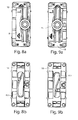
- FIG. 5 shows the guide member 8 in one of FIG. 4 corresponding representation.
- the arrangement of FIG. 5 corresponds to the arrangement of Figure 4 with the exception that on the guide member 8, a roller assembly 12 is arranged.
- the roller assembly 12 has two rollers 25, 26 which are rotatably mounted on a roller holder 27.
- the roller holder 27 in turn is connected via a rotation axis 28 pivotally connected to the guide member 8.
- This means that the roller assembly 12 is arranged pivotally limited about the pivot axis 28.
- unevenness of a running rail or curvatures of a wing spar can be compensated.
- the roller assembly 12 In a direction parallel to the pivot axis 28, the roller assembly 12 is mounted with little play, in particular in the range of 5/10 - 8/10 mm.
- a slight adjustment of the roller assembly 12 transverse to the guide member 8 is possible.
- loads on the rollers 25, 26 are kept low.
- the diameter of the roller 13 is greater than the width of the roller assembly 12th
- the FIG. 6 shows a wing attachment part 18, which in both the arrangement according to the FIG. 5 as well as in the arrangement according to the FIG. 4 can be used.
- the wing attachment part 18 has a rectilinear longitudinal slot 30 through which the control element 9 or 17 can project in order to engage the control element 10.
- the transverse guides 19, 20 are also visible.
- the transverse guides 31, 32 are designed such that a region 33 results between them, which is dovetail-shaped in cross-section.
- the region 33 in turn provides a transverse guide for the guide parts 8, 15 Due to the dovetail-shaped configuration, tilting of the guide parts 8, 15 relative to the wing attachment part 18 can be prevented.
- a fastening opening 34 is provided in the region of the transverse guide 33. Through the mounting hole 34, a screw can be screwed into the sash. Further attachment openings 35 - 38 can also be seen.
- FIG. 7 shows a view of the guide member 8.
- the control element 10 has two sections 10.1, 10.2, which are aligned differently from the Falz donors.
- the section 10.1 has a larger angle to the fold circumferential direction or longitudinal direction of the wing part 8 than the section 10.2.
- the transverse guide 33 of the wing attachment part 18 is guided in the region 35 of the guide part 8.
- FIG. 8a shows a view from below of the guide member 8 and the wing attachment portion 18.
- the guide member 8 is in a right extreme position corresponding to a closed position of the wing.
- the view of the wing attachment part 18 according to the FIG. 8b shows that the control 9 is located in section 10.2 of the control 10.
- the control 9 is shifted in Falz donorsscardi, so according to the FIG. 8b displaced upward, the control element 9 enters the area 10.1 of the control element 10, as shown in Figure 9b.
- This causes the guide member 8 is displaced to the left, as in the FIG. 9a you can see.
- This position corresponds to a sliding position, this means that a wing can be moved in this position relative to the fixed enclosure.
- FIG. 10 shows a view from the closure side of a window, a door or the like.
- the operating mechanism 2 is mounted on a wing 50. This is supported via the roller assembly 12 on a running rail 51, which is part of a bump 52. Between the wing 50 and a fixed frame 53, which is also like the bottom sill 52 part of a solid enclosure, a gap 54 can be seen. Accordingly, the wing 50 does not abut against a circumferential seal 55 which is arranged on the fixed frame 53. The roller 13 abuts against a trained as a vertical web guide 56 of the fixed enclosure. In the position shown, the wing 50 can be moved with respect to the fixed frame 53, wherein the roller 13 can be supported on the guide 56 or roll on this.
- a guide 57 is also provided on the fixed border, which is here formed like a groove.
- a roller 16 is guided, which is part of a guide member 15.
Landscapes
- Engineering & Computer Science (AREA)
- Mechanical Engineering (AREA)
- Civil Engineering (AREA)
- Structural Engineering (AREA)
- Operating, Guiding And Securing Of Roll- Type Closing Members (AREA)
- Power-Operated Mechanisms For Wings (AREA)
- Specific Sealing Or Ventilating Devices For Doors And Windows (AREA)
- Support Devices For Sliding Doors (AREA)
- Eye Examination Apparatus (AREA)
Abstract
Description
- Die Erfindung betrifft eine Verlagerungsanordnung zur Verlagerung eines Flügels, insbesondere eines Schiebeflügels, eines Fensters, einer Tür oder dergleichen relativ zu einer festen Einfassung des Fensters oder der Tür in einer Richtung quer, insbesondere senkrecht, zur Hauptebene des Fensters oder der Tür, mit einem am Flügel anordenbaren Betätigungsmechanismus, der zumindest mit einem Abschnitt in Falzumfangsrichtung bewegbar ist und einem ersten Steuerelement, das an dem Abschnitt des Betätigungsmechanismus angeordnet ist, und einem zweiten Steuerelement, das an einem Führungsteil angeordnet ist, das dazu bestimmt ist, an der festen Einfassung geführt zu werden und quer zur Falzumfangsrichtung bewegbar am Flügel angeordnet zu werden, wobei eines der Steuerelemente als sich zumindest abschnittsweise quer zur Falzumfangsrichtung erstreckende Steuerkontur und eines der Steuerelemente als mit der Steuerkontur zusammenwirkender Steuervorsprung ausgebildet ist.
- Eine derartige Verlagerungsanordnung ist beispielsweise aus der
WO 2007/075075 A1 bekannt. - Bei Schiebetüren und Schiebefenstern besteht das Problem, den Schiebeflügel gegenüber der festen Einfassung, insbesondere einem festen Rahmen, abzudichten. Ist eine Dichtung zwischen der festen Einfassung und dem Schiebeflügel angeordnet und ist der Schiebeflügel nicht quer zur Hauptebene des Fensters oder der Tür verlagerbar, so ist ein Öffnen des Schiebeflügels nur sehr schwer möglich, da dies durch die zwischen Flügel und fester Einfassung angeordnete Dichtung behindert wird.
- Um das Öffnen und Schließen des Flügels zu erleichtern, sollte dieser daher senkrecht zur Hauptebene des Fensters oder der Tür abgestellt werden können, um von der Dichtung ungestört verschoben werden zu können. Um diese Querverlagerung zu bewerkstelligen, schlägt die
WO 2007/075075 A1 vor, mithilfe eines schrägen Schlitzes in einer Treibstange und einem Bolzen, der in den schrägen Schlitz eingreift und an einem Laufwagen angeordnet ist, einen Flügel quer zur Flügelhauptebene relativ zu einem Laufwagen zu bewegen. - Wenn diese Anordnung eingesetzt wird, um den Flügel gegen eine Dichtung zu pressen, entstehen nicht unerhebliche auf den Laufwagen wirkende Kräfte. Dies kann zu einer Beschädigung oder Verkanten der Laufrollen des Laufwagens führen.
- Aufgabe der vorliegenden Erfindung ist es daher, eine konstruktiv einfache Verlagerungsanordnung bereit zu stellen, die die oben genannten Nachteile vermeidet.
- Gelöst wird diese Aufgabe erfindungsgemäß durch eine Verlagerungsanordnung zur Verlagerung eines Flügels, insbesondere eines Schiebeflügels, eines Fensters, einer Tür oder dergleichen relativ zu einer festen Einfassung des Fensters oder der Tür in einer Richtung quer, insbesondere senkrecht, zur Hauptebene des Fensters oder der Tür, mit einem am Flügel anordenbaren Betätigungsmechanismus, der zumindest mit einem Abschnitt in Falzumfangsrichtung bewegbar ist, und einem ersten Steuerelement, das an dem Abschnitt des Betätigungsmechanismus angeordnet ist, und einem zweiten Steuerelement, das an einem Führungsteil angeordnet ist, das dazu bestimmt ist, an der festen Einfassung geführt zu werden und quer zur Falzumfangsrichtung bewegbar am Flügel angeordnet zu werden, wobei eines der Steuerelemente als sich zumindest abschnittsweise quer zur Falzumfangsrichtung erstreckende Steuerkontur und eines der Steuerelemente als mit der Steuerkontur zusammenwirkender Steuervorsprung ausgebildet ist, wobei das Führungsteil eine um eine senkrecht zur Falzumfangsrichtung und parallel zur Hauptebene des Fensters oder der Tür ausgerichtete Drehachse drehbare Rolle aufweist, die sich bei montierter Verlagerungsanordnung an einem Einfassungsabschnitt abstützt.
- Wenn der Flügel relativ zur festen Einfassung parallel zur Hauptebene des Fensters oder der Tür verlagert wird, muss sich das Führungsteil relativ zur festen Einfassung bewegen. Ist an dem Führungsteil eine drehbare Rolle angeordnet, so können die zur Verschiebung des Flügels benötigten Kräfte gering gehalten werden und der Verschleiß am Führungsteil minimiert werden, da sich die Rolle an der festen Einfassung abrollen kann. Dabei kann die Rolle in einer nutartigen Führung der festen Einfassung oder an einer Führung, insbesondere einer Führungsleiste, die parallel zur Hauptebene des Fensters oder der Tür ausgerichtet ist, geführt sein. Bei einer Betätigung des Betätigungsmechanismus werden der Steuervorsprung und die Steuerkontur relativ zueinander bewegt. Dadurch, dass die Steuerkontur schräg bzw. quer zur Falzumfangsrichtung ausgerichtet ist, bedeutet dies, dass das Führungsteil relativ zum Betätigungsmechanismus, der am Flügel angeordnet ist, bewegt wird. Da das Führungsteil jedoch an der festen Einfassung geführt ist, bedeutet dies, dass der Flügel relativ zur festen Einfassung bewegt wird und somit an eine Dichtung angelegt werden kann. Anders als im Stand der Technik werden sämtliche Kräfte quer zur Falzumfangsrichtung jetzt jedoch durch die Rolle des Führungsteils aufgenommen. Laufrollen, die gegebenenfalls an dem Führungsteil angeordnet sein können, werden dadurch entlastet.
- Die Steuerkontur kann beispielsweise als gebogener oder gekrümmter Steuerschlitz ausgebildet sein. Der Steuervorsprung kann beispielsweise als Bolzen ausgebildet sein, der an einer Treibstange eines Treibstangenbeschlags angeordnet ist, wobei die Treibstange Bestandteil des Betätigungsmechanismus ist. Grundsätzlich ist es jedoch auch denkbar, beispielsweise an einer Treibstange einen Steuerschlitz vorzusehen und entsprechend am Führungsteil einen Bolzen anzuordnen.
- Insbesondere kann das Führungsteil mit einer Bodenschwelle zusammenwirken. Eine Verlagerung des Führungsteils relativ zum Flügel führt daher zu einer Verlagerung des Flügels quer zur Hauptebene des Fensters oder der Tür. Auf diese Weise kann beispielsweise eine Dichtung zwischen Flügel und fester Einfassung eingeklemmt werden. Vorzugsweise ist das Führungsteil lediglich quer zur Falzumfangsrichtung bezüglich des Flügels verlagerbar. Insbesondere ist das Führungsteil in Falzumfangsrichtung an dem Flügel vorzugsweise blockiert, so dass es sich nicht in Falzumfangsrichtung relativ zum Flügel bewegen kann.
- Besondere Vorteile ergeben sich, wenn das Führungsteil an dem Flügel geführt ist. Dadurch ergibt sich eine definierte Bewegung des Führungsteils relativ zum Flügel. Außerdem kann durch die Führung verhindert werden, dass sich das Führungsteil in Falzumfangsrichtung relativ zum Flügel bewegt. Das Führungsteil kann unmittelbar an dem Flügel angeordnet oder an einem Flügelbefestigungsteil angeordnet sein, das an einem Flügel befestigbar ist. Das Führungsteil kann am Flügel oder am Führungsbefestigungsteil geführt sein. Besonders bevorzugt ist es, wenn das Flügelbefestigungsteil zumindest eine Querführung für das Führungsteil aufweist. Durch die Querführung wird die Bewegung des Führungsteils relativ zum Flügelbefestigungsteil festgelegt. Außerdem kann durch die Querführung sichergestellt werden, dass das Führungsteil ausschließlich quer, insbesondere senkrecht, zur Hauptebene des Flügels bewegbar ist und insbesondere nicht in Falzumfangsrichtung bewegbar ist.
- Besonders bevorzugt ist es, wenn zumindest eine Querführung zumindest abschnittsweise schwalbenschwanzförmig ausgebildet ist. Entsprechend weist das Führungsteil vorzugsweise eine schwalbenschwanzförmige Ausgestaltung auf, die mit der Querführung zusammenwirkt und an diese angepasst ist. Durch die schwalbenschwanzförmige Ausgestaltung der Querführung ergibt sich eine stabile Verbindung des Flügelbefestigungsteils und des Führungsteils. Insbesondere kann dadurch verhindert werden, dass das Führungsteil relativ zum Flügelbefestigungsteil kippt. Das Flügelbefestigungsteil kann im Bereich der schwalbenschwanzförmigen Führung eine Befestigungsöffnung aufweisen. Somit kann das Flügelbefestigungsteil im Bereich der schwalbenschwanzförmigen Führung mit dem Flügelrahmen verschraubt werden. Dies trägt zur Stabilität der Verfagerungsanordnung bei. Insbesondere kann dadurch verhindert werden, dass das Flügelbefestigungsteil relativ zum Flügelrahmen kippt. Es kann somit eine Befestigung des Flügelbefestigungsteils am Flügelrahmen erfolgen, wo die stärkste Belastung für das Flügelbefestigungsteil zu erwarten ist.
- Das Flügelbefestigungsteil kann einen in Falzumfangsrichtung ausgerichteten Längsschlitz aufweisen, den der Steuervorsprung durchragt. Dadurch ist es möglich, das Flügelbefestigungsteil und das Führungsteil unmittelbar im Bereich des Betätigungsmechanismus und nicht etwa versetzt dazu anzuordnen.
- Gemäß einer vorteilhaften Ausgestaltung der Erfindung kann vorgesehen sein, dass das Flügelbefestigungsteil das Führungsteil zumindest abschnittsweise hintergreift. Dadurch wird das Führungsteil sicher am Flügelbefestigungsteil gehalten. Außerdem wird das Führungsteil an dem Flügelbefestigungsteil geführt, wenn es abschnittsweise hintergriffen wird.
- An dem Führungsteil kann zumindest eine Laufrolle angeordnet sein, über die sich der Flügel des Fensters, der Tür oder dergleichen auf einer Laufschiene abstützen kann. Insbesondere kann an dem Führungsteil ein Laufwagen angeordnet sein. Dadurch, dass sich das Führungsteil quer zur Hauptebene des Fensters oder der Tür an der festen Einfassung abstützt, werden Querkräfte auf die Laufrolle vermieden.
- Gemäß einer Weiterbildung kann vorgesehen sein, dass an dem Führungsteil eine Laufrollenanordnung vorgesehen ist, die im Bereich der Rolle um eine quer zur Falzumfangsrichtung ausgerichtete horizontale Achse schwenkbar angeordnet ist. Dabei weist die Laufrollenanordnung vorzugsweise zwei Laufrollen auf, die sich beidseits der Schwenkachse befinden. Somit kann sichergestellt werden, dass stets beide Laufrollen in Kontakt mit einer Laufschiene sind, auch wenn entweder der Flügelrahmenholm oder die Laufschiene nicht exakt gerade sind.
- Weitere Vorteile ergeben sich, wenn die Laufrollenanordnung mit Spiel in Falzquerrichtung an dem Führungsteil angeordnet ist. Auch dadurch können unerwünschte Kräfte auf die Laufrollen vermieden werden. Die Leichtgängigkeit des Schiebeflügels wird dadurch verbessert.
- Das Führungsteil kann mit dem Flügelbefestigungsteil vormontiert sein, wobei die Relativposition des Führungsteils und des Flügelbefestigungsteils durch ein Fixierungselement festgelegt ist. Dadurch wird die Montage der Verlagerungsanordnung erleichtert. Bei der ersten Querverlagerung des Flügels kann das Fixierungselement gelöst oder sogar zerstört werden. Durch das Fixierungselement können das Führungsteil und das Flügelbefestigungsteil unverlierbar aneinander gehalten werden.
- Grundsätzlich ist es denkbar, dass als Betätigungsmechanismus ein Seilzug verwendet wird. Vorteile ergeben sich jedoch, wenn als Betätigungsmechanismus ein umlaufender Treibstangenbeschlag vorgesehen ist. Der Treibstangenbeschlag erstreckt sich vorzugsweise um zumindest den überwiegenden Umfang des Flügels.
- In den Rahmen der Erfindung fällt außerdem ein Fenster, eine Tür oder dergleichen mit einer festen Einfassung, einem Flügel und einer erfindungsgemäßen Verlagerungsanordnung. Ein derart ausgestaltetes Fenster oder eine derart ausgestaltete Tür oder dergleichen können besonders zuverlässig abgedichtet werden.
- Zu diesem Zweck ist es vorteilhaft, wenn eine umlaufende Dichtung vorgesehen ist, die bei einer Querverlagerung des Flügels zwischen Flügel und fester Einfassung eingeklemmt wird. Dabei kann die Dichtung entweder an der festen Einfassung oder am Flügel angeordnet sein. Die Dichtung ist dabei vorzugsweise an der dem Flügel zugewandten Seite der festen Einfassung oder an der der festen Einfassung zugewandten Seite des Flügels angeordnet.
- Besondere Vorteile ergeben sich, wenn mehrere Führungsteile vorgesehen sind. Dabei kann an zumindest zwei Führungsteilen eine Laufrolle oder Laufrollenanordnung vorgesehen sein. An den Stellen, an denen die Führungsteile vorgesehen sind, werden Schließstellen realisiert. Diese Schließstellen kommen jedoch ohne Schließstücke aus. Unschöne sichtbare Schließstücke können also mit der erfindungsgemäßen Verlagerungsanordnung vermieden werden. Dadurch, dass auf Schließstücke verzichtet werden kann, kann auch ein ebener Durchgang bzw. eine ebene Bodenschwelle sichergestellt werden. Stolperfallen können vermieden werden.
- Grundsätzlich können beliebig viele Führungsteile vorgesehen werden. Vorzugsweise werden mehrere Führungsteile oben und unten über die Länge des Flügels verteilt vorgesehen.
- Weitere Merkmale und Vorteile der Erfindung ergeben sich aus der nachfolgenden Beschreibung eines Ausführungsbeispiels der Erfindung, anhand der Figuren der Zeichnung, die erfindungswesentliche Einzelheiten zeigen, und aus den Ansprüchen. Die einzelnen Merkmale können je einzeln für sich oder zu mehreren in beliebiger Kombination bei einer Variante der Erfindung verwirklicht sein.
- Ein bevorzugtes Ausführungsbeispiel der Erfindung ist in der Zeichnung schematisch dargestellt und wird nachfolgend mit Bezug zu den Figuren der Zeichnung näher erläutert. Es zeigen:
- Fig. 1
- eine perspektivische Ansicht einer Verlagerungsanordnung;
- Fig. 2
- eine vergrößerte Darstellung des Details A der
Figur 1 ; - Fig. 3
- eine vergrößerte Darstellung des Details B der
Figur 1 ; - Fig. 4
- eine perspektivische Darstellung eines Führungsteils, welches an einem Flügelbefestigungsteil angeordnet ist;
- Fig. 5
- eine perspektivische Darstellung eines Führungsteils, welches eine Laufrollenanordnung aufweist und an einem Flügelbefestigungsteil angeordnet ist;
- Fig. 6
- eine Ansicht eines Flügelbefestigungsteils;
- Fig. 7
- eine Ansicht des Führungsteils der
Figur 5 ; - Fig. 8a
- eine Ansicht von unten auf ein Führungsteil in Verschlussstellung;
- Fig. 8b
- eine Draufsicht auf das Flügelbefestigungsteil bei einer Verschlussstellung;
- Fig. 9a
- eine der
Figur 8a entsprechender Darstellung in einer Schiebestellung; - Fig. 9b
- eine der
Figur 8b entsprechender Darstellung ein einer Schiebestellung; - Fig. 10
- eine Ansicht von der Verschlussseite auf einen Flügel, wobei der Flügel beabstandet zu einer festen Einfassung angeordnet ist;
- Fig. 11
- eine der
Figur 10 entsprechende Darstellung, wobei der Flügel gegenüber der Darstellung derFigur 10 quer zur Hauptebene des Fensters oder der Tür verlagert wurde. - Die
Figur 1 zeigt eine Verlagerungsanordnung 1 mit einem als umlaufender Treibstangenbeschlag ausgebildeten Betätigungsmechanismus 2, der über einen Betätigungsgriff 3 betätigt werden kann. Der Betätigungsmechanismus 2 wird an einem hier nicht dargestellten Flügel eines Fensters oder Tür montiert und erstreckt sich entlang der Falzumfangsrichtung. Im gezeigten Ausführungsbeispiel weist die Verlagerungsanordnung vier Stellen 4 - 7 auf, an denen ein Führungsteil quer zur Falzumfangsrichtung bezüglich eines Flügels bzw. bezüglich des Betätigungsmechanismus 2 verlagerbar ist. - In der vergrößerten Darstellung des Details A in der
Figur 2 ist das Führungsteil 8 ohne zwischen Führungsteil 8 und Betätigungsmechanismus 2 angeordnetes Flügelbefestigungsteil dargestellt. Zu erkennen ist, dass der Betätigungsmechanismus 2 ein als Steuervorsprung ausgebildetes Steuerelement 9 aufweist, welches in ein als Steuerkontur, insbesondere Steuerschlitz, ausgebildetes Steuerelement 10 des Führungsteils 8 eingreifen kann. Der Steuerschlitz ist dabei schräg zur Falzumfangsrichtung 11 ausgerichtet. Bei einer Verlagerung des Betätigungsmechanismus 2 in Falzumfangsrichtung 11 wird somit das Führungsteil 8 senkrecht zur Falzumfangsrichtung 11 bezüglich des Betätigungsmechanismus 2 und somit des Flügels verlagert. - Das Führungsteil 8 der
Figur 2 weist eine Laufrollenanordnung 12 auf, die nachfolgend noch näher beschrieben wird. Unterhalb der Laufrollenanordnung 12 ist eine Rolle 13 zu erkennen, die um eine senkrecht zur Falzumfangsrichtung 11 und parallel zur Hauptebene einer Tür oder eines Fensters ausgerichtete Drehachse drehbar ist. Die Rolle 13 weist einen Durchmesser auf, der größer ist, als die Breite der Laufwagenanordnung 12. In Zusammenwirkung mit einer festen Einfassung kann dadurch vermieden werden, dass Querkräfte auf die Laufrollenanordnung 12 wirken - Die
Figur 3 zeigt eine Darstellung des Details B derFigur 1 in einer Explosionsdarstellung. Das Führungsteil 15 weist ebenfalls eine Rolle 16 auf, die um eine vertikale Drehachse drehbar angeordnet ist. Auch die Drehachse der Rolle 16 ist somit senkrecht zur Falzumfangsrichtung 11 und parallel zur Hauptebene ausgerichtet. Die Rolle 16 ist zur Zusammenwirkung mit einer festen Einfassung bestimmt. Das Führungsteil 15 weist keine Laufwagenanordnung auf. Gegenüberliegend dem Führungsteil 15 ist wiederum ein Steuerelement 17, welches als Steuervorsprung ausgebildet ist, vorgesehen und an dem Betätigungsmechanismus 2 angeordnet. Insbesondere kann der Steuervorsprung als Rolle ausgebildet sein, die an einer Treibstange angeordnet ist. Das Steuerelement 17 durchgreift ein Flügelbefestigungsteil 18, an dem das Führungselement 15 quer zur Falzumfangsrichtung 11 verlagerbar angeordnet ist. Das Steuerelement 17 greift in ein Steuerelement 10 des Führungselements 15 ein. - In der etwas vergrößerten perspektivischen Darstellung des Führungselements 15 gemäß der
Figur 4 ist zu erkennen, dass das Flügelbefestigungsteil 18 Querführungen 19, 20 aufweist, entlang denen das Führungsteil 15 relativ zum Flügelbefestigungsteil 18 verlagerbar ist. Weiterhin ist zu erkennen, dass das Flügelbefestigungsteil 18 das Führungsteil 15 in den Bereichen 21, 22 übergreift. Dadurch ist das Führungsteil 15 am Flügelbefestigungsteil 18 gehalten. - Die
Figur 5 zeigt das Führungsteil 8 in einer derFigur 4 entsprechenden Darstellung. Die Anordnung derFigur 5 entspricht der Anordnung der Figur 4 mit der Ausnahme, dass an dem Führungsteil 8 eine Laufrollenanordnung 12 angeordnet ist. Die Laufrollenanordnung 12 weist zwei Laufrollen 25, 26 auf, die an einem Laufrollenhalter 27 drehbar angeordnet sind. Der Laufrollenhalter 27 seinerseits ist über eine Drehachse 28 schwenkbar mit dem Führungsteil 8 verbunden. Dies bedeutet, dass die Laufrollenanordnung 12 um die Schwenkachse 28 begrenzt schwenkbar angeordnet ist. Dadurch können Unebenheiten einer Laufschiene oder auch Krümmungen eines Flügelholms ausgeglichen werden. In einer Richtung parallel zur Schwenkachse 28 ist die Laufrollenanordnung 12 mit geringem Spiel, insbesondere im Bereich von 5/10 - 8/10 mm gelagert. Somit ist auch eine geringfügige Verstellung der Laufrollenanordnung 12 quer zum Führungsteil 8 möglich. Dadurch können Belastungen auf die Laufrollen 25, 26 gering gehalten werden. Hier ist nochmals zu erkennen, dass der Durchmesser der Rolle 13 größer ist als die Breite der Laufrollenanordnung 12. - Die
Figur 6 zeigt ein Flügelbefestigungsteil 18, das sowohl in der Anordnung gemäß derFigur 5 als auch in der Anordnung gemäß derFigur 4 eingesetzt werden kann. Hier ist zu erkennen, dass das Flügelbefestigungsteil 18 einen geradlinigen Längsschlitz 30 aufweist, durch den das Steuerelement 9 bzw. 17 ragen kann, um in Eingriff mit dem Steuerelement 10 zu gelangen. Zu erkennen sind auch die Querführungen 19, 20. Die Querführungen 31, 32 sind so gestaltet, dass sich zwischen ihnen ein Bereich 33 ergibt, der im Querschnitt schwalbenschwanzförmig ist. Der Bereich 33 stellt wiederum eine Querführung für die Führungsteile 8, 15 dar. Durch die schwalbenschwanzförmige Ausgestaltung kann ein Verkippen der Führungsteile 8, 15 relativ zum Flügelbefestigungsteil 18 verhindert werden. Im Bereich der Querführung 33 ist eine Befestigungsöffnung 34 vorgesehen. Durch die Befestigungsöffnung 34 kann eine Schraube in den Flügelrahmen eingeschraubt werden. Weitere Befestigungsöffnungen 35 - 38 sind ebenfalls zu erkennen. - Die
Figur 7 zeigt eine Ansicht des Führungsteils 8. Hier ist zu erkennen, dass das Steuerelement 10 zwei Abschnitte 10.1, 10.2 aufweist, die unterschiedlich zur Falzumfangsrichtung ausgerichtet sind. Insbesondere weist der Abschnitt 10.1 einen größeren Winkel zur Falzumfangsrichtung bzw. Längsrichtung des Flügelteils 8 auf als der Abschnitt 10.2. Durch den Abschnitt 10.1 kann eine größere Querbewegung des Flügels realisiert werden, während durch den Abschnitt 10.2 ein sanftes Andrücken des Flügels an eine Dichtung sichergestellt werden kann. Die Querführung 33 des Flügelbefestigungsteils 18 wird im Bereich 35 des Führungsteils 8 geführt. - Die
Figur 8a zeigt eine Ansicht von unten auf das Führungsteil 8 und das Flügelbefestigungsteil 18. Das Führungsteil 8 befindet sich in einer rechten Extremstellung, die einer Verschlussstellung des Flügels entspricht. Die Ansicht auf das Flügelbefestigungsteil 18 gemäß derFigur 8b ergibt, dass sich das Steuerelement 9 im Abschnitt 10.2 des Steuerelements 10 befindet. Wird nun das Steuerelement 9 in Falzumfangsrichtung verlagert, also entsprechend derFigur 8b nach oben verlagert, so gelangt das Steuerelement 9 in den Bereich 10.1 des Steuerelements 10, wie dies in der Figur 9b gezeigt ist. Dies führt dazu, dass das Führungsteil 8 nach links verlagert wird, wie dies in derFigur 9a zu sehen ist. Diese Stellung entspricht einer Schiebestellung, dies bedeutet, dass ein Flügel in dieser Stellung relativ zur festen Einfassung verschoben werden kann. - Die
Figur 10 zeigt eine Ansicht von der Verschlussseite auf ein Fenster, eine Tür oder dergleichen. Der Betätigungsmechanismus 2 ist an einem Flügel 50 montiert. Dieser stützt sich über die Laufrollenanordnung 12 an einer Laufschiene 51 ab, die Bestandteil einer Bodenschwelle 52 ist. Zwischen dem Flügel 50 und einem festen Rahmen 53, der ebenfalls wie die Bodenschwelle 52 Bestandteil einer festen Einfassung ist, ist ein Spalt 54 zu sehen. Der Flügel 50 liegt demnach nicht an einer umlaufenden Dichtung 55 an, die an dem festen Rahmen 53 angeordnet ist. Die Rolle 13 liegt an einer als vertikaler Steg ausgebildeten Führung 56 der festen Einfassung an. In der gezeigten Stellung kann der Flügel 50 bezüglich des festen Rahmens 53 verschoben werden, wobei sich die Rolle 13 an der Führung 56 abstützen beziehungsweise an dieser abrollen kann. - Im oberen Bereich des Fensters ist an der festen Einfassung ebenfalls eine Führung 57 vorgesehen, die hier nutartig ausgebildet ist. In der Führung 57 ist eine Rolle 16 geführt, die Bestandteil eines Führungsteils 15 ist.
- Wird nun der Betätigungsmechanismus 2 betätigt, so ergibt sich die in der
Figur 11 gezeigte Situation. Durch Betätigen des Betätigungsmechanismus 2 werden die Steuerelemente 9, 17 verlagert, was dazu führt, dass die Laufrollenanordnung 12 und entsprechend das Führungsteil 8 relativ zum Flügelbefestigungsteil 18 unten am Flügel 50 und das Führungsteil 15 relativ zum Flügelbefestigungsteil 18 oben am Flügel 50 verlagert werden. Dies bedeutet, dass sich der Flügel 50 dem festen Rahmen 53 annähert, so dass die Dichtung 55 zwischen Flügel 50 und festen Rahmen 53 eingeklemmt wird. Der Flügel 50 liegt nun dichtend an dem festen Rahmen 53 an. Hier ist zu erkennen, dass der Flügel 50 gegen den festen Rahmen 53 gedrückt wird, da sich die Rolle 13 an der Führung 56 beziehungsweise die Rolle 16 an der Führung 57 abstützt. Es wirken somit keine Kräfte quer zur Falzumfangsrichtung auf die Laufrollenanordnung 12.
Claims (15)
- Verlagerungsanordnung (1) zur Verlagerung eines Flügels (50), insbesondere eines Schiebeflügels, eines Fensters, einer Tür oder dgl. relativ zu einer festen Einfassung (53) des Fensters oder der Tür in einer Richtung quer, insbesondere senkrecht, zur Hauptebene des Fensters oder der Tür, mit einem am Flügel (50) anordenbaren Betätigungsmechanismus (2), der zumindest mit einem Abschnitt in Falzumfangsrichtung (11) bewegbar ist, und einem ersten Steuerelement (9, 17), das an dem Abschnitt des Betätigungsmechanismus (2) angeordnet ist, und einem zweiten Steuerelement (10), das an einem Führungsteil (8, 15) angeordnet ist, das dazu bestimmt ist, an der festen Einfassung (53) geführt zu werden und quer zur Falzumfangsrichtung (11) bewegbar am Flügel (50) angeordnet zu werden, wobei eines der Steuerelemente (10) als sich zumindest abschnittsweise quer zur Falzumfangsrichtung (11) erstreckende Steuerkontur und eines der Steuerelemente (9, 17) als mit der Steuerkontur zusammen wirkender Steuervorsprung ausgebildet ist, dadurch gekennzeichnet, dass das Führungsteil (8, 15) eine um eine senkrecht zur Falzumfangsrichtung ausgerichtete Drehachse drehbare Rolle (13, 16) aufweist, die sich bei montierter Verlagerungsanordnung an einem Einfassungsabschnitt (56, 57) abstützt.
- Verlagerungsanordnung nach Anspruch 1, dadurch gekennzeichnet, dass das Führungsteil (8, 15) an einem Flügelbefestigungsteil (18) angeordnet ist.
- Verlagerungsanordnung nach Anspruch 2, dadurch gekennzeichnet, dass das Flügelbefestigungsteil (18) zumindest eine Querführung (19, 20, 31, 32, 33) für das Führungsteil (8, 15) aufweist.
- Verlagerungsanordnung nach Anspruch 3, dadurch gekennzeichnet, dass zumindest eine Querführung (33) zumindest abschnittsweise schwalbenschwanzförmig ausgebildet ist.
- Verlagerungsanordnung nach Anspruch 4, dadurch gekennzeichnet, dass das Flügelbefestigungsteil (18) im Bereich der schwalbenschwanzförmigen Führung (33) eine Befestigungsöffnung (34) aufweist.
- Verlagerungsanordnung nach einem der vorhergehenden Ansprüche 2 bis 5, dadurch gekennzeichnet, dass das Flügelbefestigungsteil (18) einen in Falzumfangsrichtung (11) ausgerichteten Längsschlitz (30) aufweist, den der Steuervorsprung durchragt.
- Verlagerungsanordnung nach einem der vorhergehenden Ansprüche 2 bis 6, dadurch gekennzeichnet, dass des Flügelbefestigungsteil (18) das Führungsteil (8, 15) zumindest abschnittsweise hintergreift.
- Verlagerungsanordnung nach einem der vorhergehenden Ansprüche, dadurch gekennzeichnet, dass an dem Führungsteil (8) zumindest eine Laufrolle (25, 26) angeordnet ist, über die sich der Flügel (50) des Fensters, der Tür oder dgl. auf einer Laufschiene (51) abstützen kann.
- Verlagerungsanordnung nach Anspruch 8, dadurch gekennzeichnet, dass an dem Führungsteil (8) eine Laufrollenanordnung (12) vorgesehen ist, die im Bereich der Rolle (13) um eine quer zur Falzumfangsrichtung (11) ausgerichtete horizontale Achse (28) schwenkbar angeordnet ist.
- Verlagerungsanordnung nach einem der vorhergehenden Ansprüche, dadurch gekennzeichnet, dass die Laufrollenanordnung (12) mit Spiel in Falzquerrichtung an dem Führungsteil (8) angeordnet ist.
- Verlagerungsanordnung nach einem der vorhergehenden Ansprüche, dadurch gekennzeichnet, dass das Führungsteil (8, 15) mit dem Flügelbefestigungsteil (18) vormontiert ist, wobei die Relativposition des Führungsteils (8, 15) und des Flügelbefestigungsteils (18) durch ein Fixierungselement festgelegt ist.
- Verlagerungsanordnung nach einem der vorhergehenden Ansprüche, dadurch gekennzeichnet, dass der Betätigungsmechanismus (2) als umlaufender Treibstangenbeschlag ausgebildet ist.
- Fenster, Tür oder dgl. mit einer festen Einfassung, einem Flügel sowie einer Verlagerungsanordnung (1) nach einem der vorhergehenden Ansprüche.
- Fenster, Tür oder dgl. nach Anspruch 13, dadurch gekennzeichnet, dass eine insbesondere umlaufende Dichtung(55) vorgesehen ist, die bei einer Querverlagerung des Flügels (50) zwischen Flügel (50) und fester Einfassung (53) eingeklemmt wird.
- Fenster, Tür oder dgl. nach einem der vorhergehenden Ansprüche 13 oder 14, dadurch gekennzeichnet, dass mehrere Führungsteile (8, 15) vorgesehen sind.
Priority Applications (9)
| Application Number | Priority Date | Filing Date | Title |
|---|---|---|---|
| PL13177345T PL2829679T3 (pl) | 2013-07-22 | 2013-07-22 | Okucie do dociskania skrzydła przesuwnego do stałego obramowania |
| EP13177345.9A EP2829679B1 (de) | 2013-07-22 | 2013-07-22 | Beschlag zum Anpressen eines Schiebeflügels an eine feste Einfassung |
| HUE13177345A HUE032513T2 (en) | 2013-07-22 | 2013-07-22 | Attachment to press a sliding wing to a fixed frame |
| DK13177345.9T DK2829679T3 (en) | 2013-07-22 | 2013-07-22 | Fittings for pressing a sliding frame against a fixed frame |
| ES13177345.9T ES2624434T3 (es) | 2013-07-22 | 2013-07-22 | Bisagra para el montaje de una hoja corredera en un bastidor fijo |
| PCT/EP2014/064911 WO2015010925A1 (de) | 2013-07-22 | 2014-07-11 | Beschlag zum anpressen eines schiebeflügels an eine feste einfassung |
| CN201480041298.9A CN105492713B (zh) | 2013-07-22 | 2014-07-11 | 用于将滑动翼扇压紧到固定围框上的配件 |
| KR1020167000758A KR102004595B1 (ko) | 2013-07-22 | 2014-07-11 | 고정 문틀 상에 슬라이딩 문짝을 압착하기 위한 기구 |
| US14/898,238 US10077594B2 (en) | 2013-07-22 | 2014-07-11 | Fitting for pressing a sliding wing onto a fixed enclosure |
Applications Claiming Priority (1)
| Application Number | Priority Date | Filing Date | Title |
|---|---|---|---|
| EP13177345.9A EP2829679B1 (de) | 2013-07-22 | 2013-07-22 | Beschlag zum Anpressen eines Schiebeflügels an eine feste Einfassung |
Publications (2)
| Publication Number | Publication Date |
|---|---|
| EP2829679A1 true EP2829679A1 (de) | 2015-01-28 |
| EP2829679B1 EP2829679B1 (de) | 2017-02-01 |
Family
ID=48856504
Family Applications (1)
| Application Number | Title | Priority Date | Filing Date |
|---|---|---|---|
| EP13177345.9A Active EP2829679B1 (de) | 2013-07-22 | 2013-07-22 | Beschlag zum Anpressen eines Schiebeflügels an eine feste Einfassung |
Country Status (9)
| Country | Link |
|---|---|
| US (1) | US10077594B2 (de) |
| EP (1) | EP2829679B1 (de) |
| KR (1) | KR102004595B1 (de) |
| CN (1) | CN105492713B (de) |
| DK (1) | DK2829679T3 (de) |
| ES (1) | ES2624434T3 (de) |
| HU (1) | HUE032513T2 (de) |
| PL (1) | PL2829679T3 (de) |
| WO (1) | WO2015010925A1 (de) |
Cited By (9)
| Publication number | Priority date | Publication date | Assignee | Title |
|---|---|---|---|---|
| WO2016058756A1 (de) * | 2014-10-15 | 2016-04-21 | Roto Frank Ag | Laufwagen eines abstellbaren schiebeflügels |
| DE102016225385A1 (de) | 2016-12-19 | 2018-06-21 | Roto Frank Ag | Verlagerungsanordnung mit Wälzlagerführung |
| DE102018116417A1 (de) | 2018-07-06 | 2020-01-09 | Roto Frank Fenster- und Türtechnologie GmbH | Vormontierte Beschlaggruppe und Beschlaganordnung für ein Fenster oder eine Tür |
| US20200199912A1 (en) * | 2018-12-19 | 2020-06-25 | Jeld-Wen, Inc. | Shoot bolt for limiting movement of a fenestration panel |
| WO2023237413A1 (de) | 2022-06-10 | 2023-12-14 | Roto Frank Fenster- und Türtechnologie GmbH | Beschlaganordnung zur anordnung zwischen einem festen rahmen und einem flügel eines fensters oder einer tür sowie fenster oder tür mit einer derartigen beschlaganordnung |
| US11851914B2 (en) | 2018-05-09 | 2023-12-26 | Roto Frank Fenster—un Tuertechnologie GmbH | Fitting arrangement for a sliding window or a sliding door |
| AT527101A1 (de) * | 2023-04-12 | 2024-10-15 | Blum Gmbh Julius | Anordnung aus einer Antriebsvorrichtung, einem Bauteil zum Verschließen einer Öffnung und einer Führungseinrichtung |
| WO2025040475A1 (de) * | 2023-08-23 | 2025-02-27 | Roto Frank Fenster- und Türtechnologie GmbH | Schiebetür mit schwenkbarer dichtleiste |
| WO2025087824A1 (de) | 2023-10-25 | 2025-05-01 | Aug. Winkhaus SE & Co. KG | Laufwagen zum verschieben eines flügels eines fensters |
Families Citing this family (21)
| Publication number | Priority date | Publication date | Assignee | Title |
|---|---|---|---|---|
| CN104863460B (zh) * | 2015-05-27 | 2017-03-15 | 广东坚朗五金制品股份有限公司 | 推拉门窗五金系统 |
| CN105909155B (zh) | 2016-06-03 | 2018-06-26 | 孙朝霞 | 门窗系统 |
| WO2019092290A1 (es) * | 2017-11-09 | 2019-05-16 | Lara Anaya Cristian | Sistema de cierre para puertas y ventanas correderas |
| US10718143B2 (en) * | 2018-02-27 | 2020-07-21 | Arconic Technologies Llc | Sliding door system |
| JP7083668B2 (ja) * | 2018-03-15 | 2022-06-13 | Ykk Ap株式会社 | 戸車、戸体及び建具 |
| NO346023B1 (en) * | 2019-08-19 | 2021-12-27 | Nordan As | Fittings for sliding doors or windows. |
| NO345579B1 (en) * | 2019-12-06 | 2021-04-26 | Wheel Me As | Releasable wheel element |
| US12084911B2 (en) | 2020-01-23 | 2024-09-10 | Cs Tech Co., Ltd. | Windows and doors assembly having ventilation function and horizontal contact function |
| DE102020210443A1 (de) * | 2020-08-17 | 2022-02-17 | Roto Frank Fenster- und Türtechnologie GmbH | Laufwagenanordnung mit wälzlagergeführter Kraftabtragung in Verschieberichtung sowie Fenster oder Tür mit einer solchen Laufwagenanordnung |
| DE102021201885A1 (de) | 2021-02-26 | 2022-09-01 | Roto Frank Fenster- und Türtechnologie GmbH | Andruckeinrichtung für ein Fenster oder eine Tür |
| DE102021201882A1 (de) * | 2021-02-26 | 2022-09-01 | Roto Frank Fenster- und Türtechnologie GmbH | Einfache Steuerzapfenbefestigung |
| KR102373584B1 (ko) * | 2021-06-18 | 2022-03-11 | 주식회사 씨에스테크 | 환기 기능 및 수평 밀착 기능을 갖는 창호 조립체 및 이에 사용되는 걸림 안내부 |
| KR102344863B1 (ko) * | 2021-10-14 | 2021-12-30 | 주식회사 다우 | 슬라이딩 창호 수평밀착용 이동체 및 이를 구비한 창호시스템 |
| CN116025249A (zh) * | 2021-10-27 | 2023-04-28 | 李辉 | 电动推拉密封窗 |
| DE102021214993A1 (de) | 2021-12-23 | 2023-06-29 | Roto Frank Fenster- und Türtechnologie GmbH | Fenster oder Tür mit einer einen Flügel präzise kontrollierenden, aber flexibel einsetzbaren Abstellmechanik |
| DE102022204890A1 (de) | 2022-05-17 | 2023-11-23 | Roto Frank Fenster- und Türtechnologie GmbH | Barrierefreie Schiebetür mit einem querabstellbaren Flügel |
| DE102022204891A1 (de) | 2022-05-17 | 2023-11-23 | Roto Frank Fenster- und Türtechnologie GmbH | Barrierefreie Schiebetür mit einem Laufwagen für einen querabstellbaren Flügel |
| DE102022205298A1 (de) | 2022-05-25 | 2023-11-30 | Roto Frank Fenster- und Türtechnologie GmbH | Führungsrolle mit zweifachem Reibmantel |
| TR2023015547A2 (tr) * | 2023-11-22 | 2023-12-21 | Ileri Pencere Kapi Sistemleri Sanayi Ve Ticaret Anonim Sirketi | Kanat merkezleme mekani̇zmasi |
| KR102774369B1 (ko) | 2024-10-07 | 2025-03-05 | 주식회사 제이제이시스템 | 미닫이창호의 횡방향 밀봉시스템 |
| KR102831270B1 (ko) | 2025-04-08 | 2025-07-08 | 주식회사 씨에스테크 | 수평 이동형 창호용 수평 이동 모듈 |
Citations (4)
| Publication number | Priority date | Publication date | Assignee | Title |
|---|---|---|---|---|
| US3660936A (en) * | 1970-12-07 | 1972-05-09 | David W Bryson | Window construction |
| FR2294312A1 (fr) * | 1974-12-12 | 1976-07-09 | Simonin Claude | Fenetre a vantail coulissant |
| WO1999060239A1 (en) * | 1998-05-20 | 1999-11-25 | Johannes Maria Musters | Assembly comprising a casing and a sliding panel |
| WO2007075075A1 (en) | 2005-12-29 | 2007-07-05 | Kwang-Seok Lee | Method and apparatus for window closing in the sliding window system |
Family Cites Families (18)
| Publication number | Priority date | Publication date | Assignee | Title |
|---|---|---|---|---|
| US3056176A (en) * | 1959-12-23 | 1962-10-02 | American Seal Kap Corp | Wall and sliding door structure |
| JPS5926751B2 (ja) * | 1979-08-16 | 1984-06-30 | ワイケイケイ株式会社 | サッシの気密装置 |
| JPS60155882U (ja) * | 1984-03-26 | 1985-10-17 | 木下 日雄 | 冷蔵庫の自動扉 |
| US5012611A (en) * | 1990-07-19 | 1991-05-07 | Lava Group Inc. | Sealing mechanism for a window set |
| US5542213A (en) * | 1994-10-27 | 1996-08-06 | Freeman Marine Equipment, Inc. | Sliding marine closure |
| US5836111A (en) * | 1996-04-16 | 1998-11-17 | Fine Industries, Inc. | Opening-closing device for windows |
| US6135511A (en) * | 1996-11-01 | 2000-10-24 | Newell Operating Company | Window locking system |
| US6497072B2 (en) * | 1997-01-10 | 2002-12-24 | Frip Ab | Sliding panel for longitudinal and lateral movement in a frame structure |
| US7708322B2 (en) * | 2001-05-30 | 2010-05-04 | Caldwell Manufacturing Company | Actuator for use in fenestration systems |
| US7845116B2 (en) | 2005-03-23 | 2010-12-07 | Sugatsune Kogyo Co., Ltd. | Guide apparatus for sliding door |
| KR100721455B1 (ko) * | 2005-12-21 | 2007-05-23 | 주식회사 엘지화학 | 시스템창호 개폐장치 |
| JP2007303109A (ja) * | 2006-05-10 | 2007-11-22 | Bs Door Kk | 懸垂引戸式ドアの開閉機構 |
| KR100963437B1 (ko) | 2008-01-29 | 2010-06-17 | 한화엘앤씨 주식회사 | 고하중 창호용 롤러 |
| KR101202093B1 (ko) | 2010-05-11 | 2012-11-15 | (주)엘지하우시스 | 수평 밀착 창호의 잠금모듈 |
| WO2012011099A1 (en) * | 2010-07-19 | 2012-01-26 | Hardoor Top Design & Technology Ltd | System of ejecting a sliding door |
| KR101280118B1 (ko) * | 2010-10-27 | 2013-07-05 | (주)엘지하우시스 | 수평밀착창호 |
| KR101254327B1 (ko) | 2012-10-24 | 2013-04-12 | (주)코리아쇼와록 | 수평밀착창호의 잠금모듈 |
| US20160130847A1 (en) * | 2014-11-12 | 2016-05-12 | Truth Hardware Corporation | Around-the-corner multi-point window lock mechanism for casement and awning windows |
-
2013
- 2013-07-22 ES ES13177345.9T patent/ES2624434T3/es active Active
- 2013-07-22 EP EP13177345.9A patent/EP2829679B1/de active Active
- 2013-07-22 HU HUE13177345A patent/HUE032513T2/en unknown
- 2013-07-22 PL PL13177345T patent/PL2829679T3/pl unknown
- 2013-07-22 DK DK13177345.9T patent/DK2829679T3/en active
-
2014
- 2014-07-11 WO PCT/EP2014/064911 patent/WO2015010925A1/de not_active Ceased
- 2014-07-11 KR KR1020167000758A patent/KR102004595B1/ko active Active
- 2014-07-11 CN CN201480041298.9A patent/CN105492713B/zh active Active
- 2014-07-11 US US14/898,238 patent/US10077594B2/en active Active
Patent Citations (4)
| Publication number | Priority date | Publication date | Assignee | Title |
|---|---|---|---|---|
| US3660936A (en) * | 1970-12-07 | 1972-05-09 | David W Bryson | Window construction |
| FR2294312A1 (fr) * | 1974-12-12 | 1976-07-09 | Simonin Claude | Fenetre a vantail coulissant |
| WO1999060239A1 (en) * | 1998-05-20 | 1999-11-25 | Johannes Maria Musters | Assembly comprising a casing and a sliding panel |
| WO2007075075A1 (en) | 2005-12-29 | 2007-07-05 | Kwang-Seok Lee | Method and apparatus for window closing in the sliding window system |
Cited By (16)
| Publication number | Priority date | Publication date | Assignee | Title |
|---|---|---|---|---|
| WO2016058756A1 (de) * | 2014-10-15 | 2016-04-21 | Roto Frank Ag | Laufwagen eines abstellbaren schiebeflügels |
| DE102016225385A1 (de) | 2016-12-19 | 2018-06-21 | Roto Frank Ag | Verlagerungsanordnung mit Wälzlagerführung |
| WO2018114337A1 (de) | 2016-12-19 | 2018-06-28 | Roto Frank Ag | Verlagerungsanordnung mit wälzlagerführung |
| US11085216B2 (en) | 2016-12-19 | 2021-08-10 | Roto Frank Fenster- Und Tuertechnologie Gmbh | Displacement arrangement having a rolling bearing guide |
| US11851914B2 (en) | 2018-05-09 | 2023-12-26 | Roto Frank Fenster—un Tuertechnologie GmbH | Fitting arrangement for a sliding window or a sliding door |
| DE102018116417A1 (de) | 2018-07-06 | 2020-01-09 | Roto Frank Fenster- und Türtechnologie GmbH | Vormontierte Beschlaggruppe und Beschlaganordnung für ein Fenster oder eine Tür |
| WO2020007830A1 (de) | 2018-07-06 | 2020-01-09 | Roto Frank Fenster- und Türtechnologie GmbH | Vormontierte beschlaggruppe und beschlaganordnung für ein fenster oder eine tür |
| US11428033B2 (en) | 2018-07-06 | 2022-08-30 | Roto Frank Fenster—und Tuertechnologie GmbH | Pre-assembled fitting group and fitting assembly for a window or a door |
| US11585122B2 (en) * | 2018-12-19 | 2023-02-21 | Jeld-Wen, Inc. | Shoot bolt for limiting movement of a fenestration panel |
| US20200199912A1 (en) * | 2018-12-19 | 2020-06-25 | Jeld-Wen, Inc. | Shoot bolt for limiting movement of a fenestration panel |
| WO2023237413A1 (de) | 2022-06-10 | 2023-12-14 | Roto Frank Fenster- und Türtechnologie GmbH | Beschlaganordnung zur anordnung zwischen einem festen rahmen und einem flügel eines fensters oder einer tür sowie fenster oder tür mit einer derartigen beschlaganordnung |
| DE102022114632A1 (de) | 2022-06-10 | 2023-12-21 | Roto Frank Fenster- und Türtechnologie GmbH | Beschlaganordnung zur Anordnung zwischen einem festen Rahmen und einem Flügel eines Fensters oder einer Tür sowie Fenster oder Tür mit einer derartigen Beschlaganordnung |
| US12480344B2 (en) | 2022-06-10 | 2025-11-25 | Roto Frank Fenster—und Türtechnologie GmbH | Fitting assembly for arranging between a fixed frame and a leaf of a window or door |
| AT527101A1 (de) * | 2023-04-12 | 2024-10-15 | Blum Gmbh Julius | Anordnung aus einer Antriebsvorrichtung, einem Bauteil zum Verschließen einer Öffnung und einer Führungseinrichtung |
| WO2025040475A1 (de) * | 2023-08-23 | 2025-02-27 | Roto Frank Fenster- und Türtechnologie GmbH | Schiebetür mit schwenkbarer dichtleiste |
| WO2025087824A1 (de) | 2023-10-25 | 2025-05-01 | Aug. Winkhaus SE & Co. KG | Laufwagen zum verschieben eines flügels eines fensters |
Also Published As
| Publication number | Publication date |
|---|---|
| US10077594B2 (en) | 2018-09-18 |
| EP2829679B1 (de) | 2017-02-01 |
| WO2015010925A1 (de) | 2015-01-29 |
| KR102004595B1 (ko) | 2019-07-26 |
| HUE032513T2 (en) | 2017-09-28 |
| US20160145932A1 (en) | 2016-05-26 |
| CN105492713B (zh) | 2017-07-07 |
| KR20160033690A (ko) | 2016-03-28 |
| ES2624434T3 (es) | 2017-07-14 |
| CN105492713A (zh) | 2016-04-13 |
| DK2829679T3 (en) | 2017-04-24 |
| PL2829679T3 (pl) | 2017-09-29 |
Similar Documents
| Publication | Publication Date | Title |
|---|---|---|
| EP2829679B1 (de) | Beschlag zum Anpressen eines Schiebeflügels an eine feste Einfassung | |
| EP3818228A1 (de) | Vormontierte beschlaggruppe und beschlaganordnung für ein fenster oder eine tür | |
| EP2682545B1 (de) | Verschlussanordnung für eine Schiebetür oder ein Schiebefenster, und Schiebetür oder Schiebefenster | |
| EP4473182B1 (de) | Profilanordnung eines fensters oder einer tür mit einem flügelprofil, insbesondere einem schiebeflügelprofil | |
| EP3102759B1 (de) | Beschlag eines zumindest hebbaren und verschiebbaren flügels von fenstern oder türen | |
| EP1816295B1 (de) | Insektenschutztür | |
| EP2871312B1 (de) | Spaltlüftungsanordnung für eine Schiebetür oder -fenster und Schiebetür oder -fenster | |
| EP3060736A1 (de) | Beschlag für fenster, türen oder dergleichen | |
| EP3055472A1 (de) | Beschlag eines zumindest hebbaren, vorzugsweise aber auch verschiebbaren flügels von fenstern oder türen | |
| EP3401483A1 (de) | Beschlaganordnung sowie fenster, tür oder dergleichen mit einer derartigen beschlaganordnung | |
| EP3728778B1 (de) | Türflügel mit dichtungssystem | |
| DE102012202981B4 (de) | Beschlag für einen parallel abstellbaren und in dieser Lage verschiebbaren Flügel eines Fensters, einer Tür oder dergleichen | |
| DE3617216C2 (de) | ||
| EP2987939A1 (de) | Flügelüberschlagslüfter mit schräg verschiebbarem dichtungsschieber | |
| DE102012213786B3 (de) | Verlagerungsanordnung zur Verlagerung eines Flügels eines Fensters, einer Tür oder dergleichen relativ zu einer festen Einfassung | |
| EP1614844A2 (de) | Drehlagervorrichtung | |
| EP3235988A1 (de) | Fenstersystem und/oder türsystem | |
| EP1231345B1 (de) | Gesteuerte Verriegelungsvorrichtung und Eckumlenkung | |
| EP0280950B1 (de) | Beschlag für ein Fenster, eine Tür od. dgl. | |
| EP2685040B1 (de) | Vorspannbauteil und arbeitsverfahren für ein fenster oder eine fenstertür | |
| EP2690241B1 (de) | Beschlag für eine parallel abstellbare Schiebetür oder ein parallel abstellbares Schiebefenster | |
| EP0429981B1 (de) | Verdeckt im Falz angeordneter Beschlag für Kipp-Schwenk-flügelfenster oder -türen, insb. mit Holzrahmen | |
| DE3905995C2 (de) | ||
| EP3444417B1 (de) | Ladensystem für gebäudeöffnungen | |
| EP1582671B1 (de) | Getriebe für Flügel von Fenstern oder Türen |
Legal Events
| Date | Code | Title | Description |
|---|---|---|---|
| 17P | Request for examination filed |
Effective date: 20130722 |
|
| AK | Designated contracting states |
Kind code of ref document: A1 Designated state(s): AL AT BE BG CH CY CZ DE DK EE ES FI FR GB GR HR HU IE IS IT LI LT LU LV MC MK MT NL NO PL PT RO RS SE SI SK SM TR |
|
| AX | Request for extension of the european patent |
Extension state: BA ME |
|
| PUAI | Public reference made under article 153(3) epc to a published international application that has entered the european phase |
Free format text: ORIGINAL CODE: 0009012 |
|
| R17P | Request for examination filed (corrected) |
Effective date: 20150708 |
|
| RBV | Designated contracting states (corrected) |
Designated state(s): AL AT BE BG CH CY CZ DE DK EE ES FI FR GB GR HR HU IE IS IT LI LT LU LV MC MK MT NL NO PL PT RO RS SE SI SK SM TR |
|
| 17Q | First examination report despatched |
Effective date: 20151030 |
|
| GRAP | Despatch of communication of intention to grant a patent |
Free format text: ORIGINAL CODE: EPIDOSNIGR1 |
|
| INTG | Intention to grant announced |
Effective date: 20160405 |
|
| GRAS | Grant fee paid |
Free format text: ORIGINAL CODE: EPIDOSNIGR3 |
|
| GRAA | (expected) grant |
Free format text: ORIGINAL CODE: 0009210 |
|
| AK | Designated contracting states |
Kind code of ref document: B1 Designated state(s): AL AT BE BG CH CY CZ DE DK EE ES FI FR GB GR HR HU IE IS IT LI LT LU LV MC MK MT NL NO PL PT RO RS SE SI SK SM TR |
|
| REG | Reference to a national code |
Ref country code: GB Ref legal event code: FG4D Free format text: NOT ENGLISH |
|
| REG | Reference to a national code |
Ref country code: AT Ref legal event code: REF Ref document number: 865756 Country of ref document: AT Kind code of ref document: T Effective date: 20170215 Ref country code: CH Ref legal event code: EP |
|
| REG | Reference to a national code |
Ref country code: IE Ref legal event code: FG4D Free format text: LANGUAGE OF EP DOCUMENT: GERMAN |
|
| REG | Reference to a national code |
Ref country code: DE Ref legal event code: R096 Ref document number: 502013006216 Country of ref document: DE |
|
| REG | Reference to a national code |
Ref country code: NL Ref legal event code: FP |
|
| REG | Reference to a national code |
Ref country code: DK Ref legal event code: T3 Effective date: 20170419 |
|
| REG | Reference to a national code |
Ref country code: SE Ref legal event code: TRGR |
|
| REG | Reference to a national code |
Ref country code: RO Ref legal event code: EPE |
|
| REG | Reference to a national code |
Ref country code: NO Ref legal event code: T2 Effective date: 20170201 |
|
| REG | Reference to a national code |
Ref country code: LT Ref legal event code: MG4D |
|
| REG | Reference to a national code |
Ref country code: ES Ref legal event code: FG2A Ref document number: 2624434 Country of ref document: ES Kind code of ref document: T3 Effective date: 20170714 |
|
| REG | Reference to a national code |
Ref country code: FR Ref legal event code: PLFP Year of fee payment: 5 |
|
| PG25 | Lapsed in a contracting state [announced via postgrant information from national office to epo] |
Ref country code: HR Free format text: LAPSE BECAUSE OF FAILURE TO SUBMIT A TRANSLATION OF THE DESCRIPTION OR TO PAY THE FEE WITHIN THE PRESCRIBED TIME-LIMIT Effective date: 20170201 Ref country code: IS Free format text: LAPSE BECAUSE OF FAILURE TO SUBMIT A TRANSLATION OF THE DESCRIPTION OR TO PAY THE FEE WITHIN THE PRESCRIBED TIME-LIMIT Effective date: 20170601 Ref country code: GR Free format text: LAPSE BECAUSE OF FAILURE TO SUBMIT A TRANSLATION OF THE DESCRIPTION OR TO PAY THE FEE WITHIN THE PRESCRIBED TIME-LIMIT Effective date: 20170502 Ref country code: FI Free format text: LAPSE BECAUSE OF FAILURE TO SUBMIT A TRANSLATION OF THE DESCRIPTION OR TO PAY THE FEE WITHIN THE PRESCRIBED TIME-LIMIT Effective date: 20170201 Ref country code: LT Free format text: LAPSE BECAUSE OF FAILURE TO SUBMIT A TRANSLATION OF THE DESCRIPTION OR TO PAY THE FEE WITHIN THE PRESCRIBED TIME-LIMIT Effective date: 20170201 |
|
| PG25 | Lapsed in a contracting state [announced via postgrant information from national office to epo] |
Ref country code: PT Free format text: LAPSE BECAUSE OF FAILURE TO SUBMIT A TRANSLATION OF THE DESCRIPTION OR TO PAY THE FEE WITHIN THE PRESCRIBED TIME-LIMIT Effective date: 20170601 Ref country code: LV Free format text: LAPSE BECAUSE OF FAILURE TO SUBMIT A TRANSLATION OF THE DESCRIPTION OR TO PAY THE FEE WITHIN THE PRESCRIBED TIME-LIMIT Effective date: 20170201 Ref country code: RS Free format text: LAPSE BECAUSE OF FAILURE TO SUBMIT A TRANSLATION OF THE DESCRIPTION OR TO PAY THE FEE WITHIN THE PRESCRIBED TIME-LIMIT Effective date: 20170201 Ref country code: BG Free format text: LAPSE BECAUSE OF FAILURE TO SUBMIT A TRANSLATION OF THE DESCRIPTION OR TO PAY THE FEE WITHIN THE PRESCRIBED TIME-LIMIT Effective date: 20170501 |
|
| REG | Reference to a national code |
Ref country code: HU Ref legal event code: AG4A Ref document number: E032513 Country of ref document: HU |
|
| PG25 | Lapsed in a contracting state [announced via postgrant information from national office to epo] |
Ref country code: CZ Free format text: LAPSE BECAUSE OF FAILURE TO SUBMIT A TRANSLATION OF THE DESCRIPTION OR TO PAY THE FEE WITHIN THE PRESCRIBED TIME-LIMIT Effective date: 20170201 Ref country code: EE Free format text: LAPSE BECAUSE OF FAILURE TO SUBMIT A TRANSLATION OF THE DESCRIPTION OR TO PAY THE FEE WITHIN THE PRESCRIBED TIME-LIMIT Effective date: 20170201 Ref country code: SK Free format text: LAPSE BECAUSE OF FAILURE TO SUBMIT A TRANSLATION OF THE DESCRIPTION OR TO PAY THE FEE WITHIN THE PRESCRIBED TIME-LIMIT Effective date: 20170201 |
|
| PGFP | Annual fee paid to national office [announced via postgrant information from national office to epo] |
Ref country code: CH Payment date: 20170724 Year of fee payment: 5 Ref country code: RO Payment date: 20170714 Year of fee payment: 5 |
|
| REG | Reference to a national code |
Ref country code: DE Ref legal event code: R097 Ref document number: 502013006216 Country of ref document: DE |
|
| PG25 | Lapsed in a contracting state [announced via postgrant information from national office to epo] |
Ref country code: SM Free format text: LAPSE BECAUSE OF FAILURE TO SUBMIT A TRANSLATION OF THE DESCRIPTION OR TO PAY THE FEE WITHIN THE PRESCRIBED TIME-LIMIT Effective date: 20170201 |
|
| PGFP | Annual fee paid to national office [announced via postgrant information from national office to epo] |
Ref country code: HU Payment date: 20170713 Year of fee payment: 5 |
|
| PLBE | No opposition filed within time limit |
Free format text: ORIGINAL CODE: 0009261 |
|
| STAA | Information on the status of an ep patent application or granted ep patent |
Free format text: STATUS: NO OPPOSITION FILED WITHIN TIME LIMIT |
|
| 26N | No opposition filed |
Effective date: 20171103 |
|
| PG25 | Lapsed in a contracting state [announced via postgrant information from national office to epo] |
Ref country code: SI Free format text: LAPSE BECAUSE OF FAILURE TO SUBMIT A TRANSLATION OF THE DESCRIPTION OR TO PAY THE FEE WITHIN THE PRESCRIBED TIME-LIMIT Effective date: 20170201 |
|
| REG | Reference to a national code |
Ref country code: IE Ref legal event code: MM4A |
|
| PG25 | Lapsed in a contracting state [announced via postgrant information from national office to epo] |
Ref country code: IE Free format text: LAPSE BECAUSE OF NON-PAYMENT OF DUE FEES Effective date: 20170722 |
|
| PG25 | Lapsed in a contracting state [announced via postgrant information from national office to epo] |
Ref country code: LU Free format text: LAPSE BECAUSE OF NON-PAYMENT OF DUE FEES Effective date: 20170722 |
|
| REG | Reference to a national code |
Ref country code: FR Ref legal event code: PLFP Year of fee payment: 6 |
|
| PG25 | Lapsed in a contracting state [announced via postgrant information from national office to epo] |
Ref country code: MT Free format text: LAPSE BECAUSE OF FAILURE TO SUBMIT A TRANSLATION OF THE DESCRIPTION OR TO PAY THE FEE WITHIN THE PRESCRIBED TIME-LIMIT Effective date: 20170201 |
|
| REG | Reference to a national code |
Ref country code: CH Ref legal event code: PL |
|
| PG25 | Lapsed in a contracting state [announced via postgrant information from national office to epo] |
Ref country code: LI Free format text: LAPSE BECAUSE OF NON-PAYMENT OF DUE FEES Effective date: 20180731 Ref country code: HU Free format text: LAPSE BECAUSE OF NON-PAYMENT OF DUE FEES Effective date: 20180723 Ref country code: CH Free format text: LAPSE BECAUSE OF NON-PAYMENT OF DUE FEES Effective date: 20180731 |
|
| PG25 | Lapsed in a contracting state [announced via postgrant information from national office to epo] |
Ref country code: MC Free format text: LAPSE BECAUSE OF FAILURE TO SUBMIT A TRANSLATION OF THE DESCRIPTION OR TO PAY THE FEE WITHIN THE PRESCRIBED TIME-LIMIT Effective date: 20170201 |
|
| PG25 | Lapsed in a contracting state [announced via postgrant information from national office to epo] |
Ref country code: CY Free format text: LAPSE BECAUSE OF FAILURE TO SUBMIT A TRANSLATION OF THE DESCRIPTION OR TO PAY THE FEE WITHIN THE PRESCRIBED TIME-LIMIT Effective date: 20170201 |
|
| PG25 | Lapsed in a contracting state [announced via postgrant information from national office to epo] |
Ref country code: MK Free format text: LAPSE BECAUSE OF FAILURE TO SUBMIT A TRANSLATION OF THE DESCRIPTION OR TO PAY THE FEE WITHIN THE PRESCRIBED TIME-LIMIT Effective date: 20170201 |
|
| PG25 | Lapsed in a contracting state [announced via postgrant information from national office to epo] |
Ref country code: RO Free format text: LAPSE BECAUSE OF NON-PAYMENT OF DUE FEES Effective date: 20180722 |
|
| PG25 | Lapsed in a contracting state [announced via postgrant information from national office to epo] |
Ref country code: AL Free format text: LAPSE BECAUSE OF FAILURE TO SUBMIT A TRANSLATION OF THE DESCRIPTION OR TO PAY THE FEE WITHIN THE PRESCRIBED TIME-LIMIT Effective date: 20170201 |
|
| REG | Reference to a national code |
Ref country code: DE Ref legal event code: R081 Ref document number: 502013006216 Country of ref document: DE Owner name: ROTO FRANK FENSTER- UND TUERTECHNOLOGIE GMBH, DE Free format text: FORMER OWNER: ROTO FRANK AG, 70771 LEINFELDEN-ECHTERDINGEN, DE |
|
| PGFP | Annual fee paid to national office [announced via postgrant information from national office to epo] |
Ref country code: NL Payment date: 20250723 Year of fee payment: 13 |
|
| PGFP | Annual fee paid to national office [announced via postgrant information from national office to epo] |
Ref country code: ES Payment date: 20250819 Year of fee payment: 13 |
|
| PGFP | Annual fee paid to national office [announced via postgrant information from national office to epo] |
Ref country code: DK Payment date: 20250723 Year of fee payment: 13 Ref country code: DE Payment date: 20250722 Year of fee payment: 13 |
|
| PGFP | Annual fee paid to national office [announced via postgrant information from national office to epo] |
Ref country code: NO Payment date: 20250722 Year of fee payment: 13 |
|
| PGFP | Annual fee paid to national office [announced via postgrant information from national office to epo] |
Ref country code: PL Payment date: 20250710 Year of fee payment: 13 Ref country code: TR Payment date: 20250717 Year of fee payment: 13 Ref country code: IT Payment date: 20250731 Year of fee payment: 13 |
|
| PGFP | Annual fee paid to national office [announced via postgrant information from national office to epo] |
Ref country code: BE Payment date: 20250722 Year of fee payment: 13 Ref country code: GB Payment date: 20250724 Year of fee payment: 13 |
|
| PGFP | Annual fee paid to national office [announced via postgrant information from national office to epo] |
Ref country code: FR Payment date: 20250723 Year of fee payment: 13 Ref country code: AT Payment date: 20250721 Year of fee payment: 13 |
|
| PGFP | Annual fee paid to national office [announced via postgrant information from national office to epo] |
Ref country code: SE Payment date: 20250723 Year of fee payment: 13 |