EP2819232B1 - Apparatus for preparing electrode assembly - Google Patents
Apparatus for preparing electrode assembly Download PDFInfo
- Publication number
- EP2819232B1 EP2819232B1 EP14740350.5A EP14740350A EP2819232B1 EP 2819232 B1 EP2819232 B1 EP 2819232B1 EP 14740350 A EP14740350 A EP 14740350A EP 2819232 B1 EP2819232 B1 EP 2819232B1
- Authority
- EP
- European Patent Office
- Prior art keywords
- polymer particles
- mean
- substrate
- separator
- adhesive layer
- Prior art date
- Legal status (The legal status is an assumption and is not a legal conclusion. Google has not performed a legal analysis and makes no representation as to the accuracy of the status listed.)
- Active
Links
- 229920000642 polymer Polymers 0.000 claims description 69
- 239000002245 particle Substances 0.000 claims description 63
- 239000000758 substrate Substances 0.000 claims description 48
- 239000012790 adhesive layer Substances 0.000 claims description 38
- 229910052744 lithium Inorganic materials 0.000 claims description 27
- WHXSMMKQMYFTQS-UHFFFAOYSA-N Lithium Chemical compound [Li] WHXSMMKQMYFTQS-UHFFFAOYSA-N 0.000 claims description 26
- 238000007639 printing Methods 0.000 claims description 19
- 238000007600 charging Methods 0.000 claims description 15
- 238000010030 laminating Methods 0.000 claims description 13
- 239000011248 coating agent Substances 0.000 claims description 10
- 238000000576 coating method Methods 0.000 claims description 10
- 238000003860 storage Methods 0.000 claims description 10
- 238000000034 method Methods 0.000 claims description 7
- 238000003475 lamination Methods 0.000 claims description 6
- 239000013013 elastic material Substances 0.000 claims description 3
- 239000010410 layer Substances 0.000 claims description 3
- 238000012546 transfer Methods 0.000 claims description 3
- 238000004804 winding Methods 0.000 claims description 3
- 229920001971 elastomer Polymers 0.000 claims description 2
- 229910052751 metal Inorganic materials 0.000 claims description 2
- 239000002184 metal Substances 0.000 claims description 2
- 239000010954 inorganic particle Substances 0.000 description 28
- 239000000203 mixture Substances 0.000 description 18
- -1 polyethylene Polymers 0.000 description 16
- HBBGRARXTFLTSG-UHFFFAOYSA-N Lithium ion Chemical compound [Li+] HBBGRARXTFLTSG-UHFFFAOYSA-N 0.000 description 12
- 229910001416 lithium ion Inorganic materials 0.000 description 12
- 239000002904 solvent Substances 0.000 description 12
- 239000003792 electrolyte Substances 0.000 description 8
- RTZKZFJDLAIYFH-UHFFFAOYSA-N Diethyl ether Chemical compound CCOCC RTZKZFJDLAIYFH-UHFFFAOYSA-N 0.000 description 7
- VYPSYNLAJGMNEJ-UHFFFAOYSA-N Silicium dioxide Chemical compound O=[Si]=O VYPSYNLAJGMNEJ-UHFFFAOYSA-N 0.000 description 7
- 239000011247 coating layer Substances 0.000 description 6
- 239000003960 organic solvent Substances 0.000 description 6
- 239000008151 electrolyte solution Substances 0.000 description 5
- 239000011888 foil Substances 0.000 description 5
- 229910003002 lithium salt Inorganic materials 0.000 description 5
- 159000000002 lithium salts Chemical class 0.000 description 5
- 239000004745 nonwoven fabric Substances 0.000 description 5
- 229920000098 polyolefin Polymers 0.000 description 5
- 229920000131 polyvinylidene Polymers 0.000 description 5
- OKTJSMMVPCPJKN-UHFFFAOYSA-N Carbon Chemical compound [C] OKTJSMMVPCPJKN-UHFFFAOYSA-N 0.000 description 4
- BVKZGUZCCUSVTD-UHFFFAOYSA-L Carbonate Chemical compound [O-]C([O-])=O BVKZGUZCCUSVTD-UHFFFAOYSA-L 0.000 description 4
- PXHVJJICTQNCMI-UHFFFAOYSA-N Nickel Chemical compound [Ni] PXHVJJICTQNCMI-UHFFFAOYSA-N 0.000 description 4
- 150000005676 cyclic carbonates Chemical class 0.000 description 4
- 238000001035 drying Methods 0.000 description 4
- 238000004519 manufacturing process Methods 0.000 description 4
- 239000011255 nonaqueous electrolyte Substances 0.000 description 4
- 150000003839 salts Chemical class 0.000 description 4
- OIFBSDVPJOWBCH-UHFFFAOYSA-N Diethyl carbonate Chemical compound CCOC(=O)OCC OIFBSDVPJOWBCH-UHFFFAOYSA-N 0.000 description 3
- XEKOWRVHYACXOJ-UHFFFAOYSA-N Ethyl acetate Chemical compound CCOC(C)=O XEKOWRVHYACXOJ-UHFFFAOYSA-N 0.000 description 3
- KMTRUDSVKNLOMY-UHFFFAOYSA-N Ethylene carbonate Chemical compound O=C1OCCO1 KMTRUDSVKNLOMY-UHFFFAOYSA-N 0.000 description 3
- 239000004698 Polyethylene Substances 0.000 description 3
- 239000006183 anode active material Substances 0.000 description 3
- 239000006182 cathode active material Substances 0.000 description 3
- 230000000694 effects Effects 0.000 description 3
- 239000011521 glass Substances 0.000 description 3
- 238000007648 laser printing Methods 0.000 description 3
- 229920000573 polyethylene Polymers 0.000 description 3
- 239000011148 porous material Substances 0.000 description 3
- 238000002360 preparation method Methods 0.000 description 3
- RUOJZAUFBMNUDX-UHFFFAOYSA-N propylene carbonate Chemical compound CC1COC(=O)O1 RUOJZAUFBMNUDX-UHFFFAOYSA-N 0.000 description 3
- 239000000377 silicon dioxide Substances 0.000 description 3
- KXJGSNRAQWDDJT-UHFFFAOYSA-N 1-acetyl-5-bromo-2h-indol-3-one Chemical compound BrC1=CC=C2N(C(=O)C)CC(=O)C2=C1 KXJGSNRAQWDDJT-UHFFFAOYSA-N 0.000 description 2
- XCKPLVGWGCWOMD-YYEYMFTQSA-N 3-[[(2r,3r,4s,5r,6r)-6-[(2s,3s,4r,5r)-3,4-bis(2-cyanoethoxy)-2,5-bis(2-cyanoethoxymethyl)oxolan-2-yl]oxy-3,4,5-tris(2-cyanoethoxy)oxan-2-yl]methoxy]propanenitrile Chemical compound N#CCCO[C@H]1[C@H](OCCC#N)[C@@H](COCCC#N)O[C@@]1(COCCC#N)O[C@@H]1[C@H](OCCC#N)[C@@H](OCCC#N)[C@H](OCCC#N)[C@@H](COCCC#N)O1 XCKPLVGWGCWOMD-YYEYMFTQSA-N 0.000 description 2
- YEJRWHAVMIAJKC-UHFFFAOYSA-N 4-Butyrolactone Chemical compound O=C1CCCO1 YEJRWHAVMIAJKC-UHFFFAOYSA-N 0.000 description 2
- SBLRHMKNNHXPHG-UHFFFAOYSA-N 4-fluoro-1,3-dioxolan-2-one Chemical compound FC1COC(=O)O1 SBLRHMKNNHXPHG-UHFFFAOYSA-N 0.000 description 2
- FHVDTGUDJYJELY-UHFFFAOYSA-N 6-{[2-carboxy-4,5-dihydroxy-6-(phosphanyloxy)oxan-3-yl]oxy}-4,5-dihydroxy-3-phosphanyloxane-2-carboxylic acid Chemical compound O1C(C(O)=O)C(P)C(O)C(O)C1OC1C(C(O)=O)OC(OP)C(O)C1O FHVDTGUDJYJELY-UHFFFAOYSA-N 0.000 description 2
- ODINCKMPIJJUCX-UHFFFAOYSA-N Calcium oxide Chemical compound [Ca]=O ODINCKMPIJJUCX-UHFFFAOYSA-N 0.000 description 2
- 229920002134 Carboxymethyl cellulose Polymers 0.000 description 2
- 229920008347 Cellulose acetate propionate Polymers 0.000 description 2
- LCGLNKUTAGEVQW-UHFFFAOYSA-N Dimethyl ether Chemical compound COC LCGLNKUTAGEVQW-UHFFFAOYSA-N 0.000 description 2
- CPLXHLVBOLITMK-UHFFFAOYSA-N Magnesium oxide Chemical compound [Mg]=O CPLXHLVBOLITMK-UHFFFAOYSA-N 0.000 description 2
- 229910020231 Pb(Mg1/3Nb2/3)O3-xPbTiO3 Inorganic materials 0.000 description 2
- 229910020226 Pb(Mg1/3Nb2/3)O3−xPbTiO3 Inorganic materials 0.000 description 2
- 229910020351 Pb1-xLaxZr1-yTiyO3 Inorganic materials 0.000 description 2
- 229910020345 Pb1−xLaxZr1−yTiyO3 Inorganic materials 0.000 description 2
- 229920003171 Poly (ethylene oxide) Polymers 0.000 description 2
- 239000004696 Poly ether ether ketone Substances 0.000 description 2
- 239000004952 Polyamide Substances 0.000 description 2
- 239000004642 Polyimide Substances 0.000 description 2
- 239000004721 Polyphenylene oxide Substances 0.000 description 2
- 239000004734 Polyphenylene sulfide Substances 0.000 description 2
- 239000004743 Polypropylene Substances 0.000 description 2
- 239000004373 Pullulan Substances 0.000 description 2
- 229920001218 Pullulan Polymers 0.000 description 2
- GWEVSGVZZGPLCZ-UHFFFAOYSA-N Titan oxide Chemical compound O=[Ti]=O GWEVSGVZZGPLCZ-UHFFFAOYSA-N 0.000 description 2
- XLOMVQKBTHCTTD-UHFFFAOYSA-N Zinc monoxide Chemical compound [Zn]=O XLOMVQKBTHCTTD-UHFFFAOYSA-N 0.000 description 2
- MCMNRKCIXSYSNV-UHFFFAOYSA-N Zirconium dioxide Chemical compound O=[Zr]=O MCMNRKCIXSYSNV-UHFFFAOYSA-N 0.000 description 2
- 229940072056 alginate Drugs 0.000 description 2
- 235000010443 alginic acid Nutrition 0.000 description 2
- 229920000615 alginic acid Polymers 0.000 description 2
- 229910002113 barium titanate Inorganic materials 0.000 description 2
- 230000015572 biosynthetic process Effects 0.000 description 2
- 229920002301 cellulose acetate Polymers 0.000 description 2
- 229920006217 cellulose acetate butyrate Polymers 0.000 description 2
- 238000004140 cleaning Methods 0.000 description 2
- IEJIGPNLZYLLBP-UHFFFAOYSA-N dimethyl carbonate Chemical compound COC(=O)OC IEJIGPNLZYLLBP-UHFFFAOYSA-N 0.000 description 2
- 238000004146 energy storage Methods 0.000 description 2
- 238000005516 engineering process Methods 0.000 description 2
- 150000002148 esters Chemical class 0.000 description 2
- JBTWLSYIZRCDFO-UHFFFAOYSA-N ethyl methyl carbonate Chemical compound CCOC(=O)OC JBTWLSYIZRCDFO-UHFFFAOYSA-N 0.000 description 2
- FKRCODPIKNYEAC-UHFFFAOYSA-N ethyl propionate Chemical compound CCOC(=O)CC FKRCODPIKNYEAC-UHFFFAOYSA-N 0.000 description 2
- 239000000446 fuel Substances 0.000 description 2
- JBFHTYHTHYHCDJ-UHFFFAOYSA-N gamma-caprolactone Chemical compound CCC1CCC(=O)O1 JBFHTYHTHYHCDJ-UHFFFAOYSA-N 0.000 description 2
- GAEKPEKOJKCEMS-UHFFFAOYSA-N gamma-valerolactone Chemical compound CC1CCC(=O)O1 GAEKPEKOJKCEMS-UHFFFAOYSA-N 0.000 description 2
- CJNBYAVZURUTKZ-UHFFFAOYSA-N hafnium(IV) oxide Inorganic materials O=[Hf]=O CJNBYAVZURUTKZ-UHFFFAOYSA-N 0.000 description 2
- 150000004820 halides Chemical class 0.000 description 2
- 229920001903 high density polyethylene Polymers 0.000 description 2
- 229920000092 linear low density polyethylene Polymers 0.000 description 2
- 229910001386 lithium phosphate Inorganic materials 0.000 description 2
- 229920001684 low density polyethylene Polymers 0.000 description 2
- 239000012528 membrane Substances 0.000 description 2
- 238000012986 modification Methods 0.000 description 2
- 230000004048 modification Effects 0.000 description 2
- 239000002105 nanoparticle Substances 0.000 description 2
- 229910052759 nickel Inorganic materials 0.000 description 2
- 229920001485 poly(butyl acrylate) polymer Polymers 0.000 description 2
- 229920003207 poly(ethylene-2,6-naphthalate) Polymers 0.000 description 2
- 229920003229 poly(methyl methacrylate) Polymers 0.000 description 2
- 229920005569 poly(vinylidene fluoride-co-hexafluoropropylene) Polymers 0.000 description 2
- 229920002239 polyacrylonitrile Polymers 0.000 description 2
- 229920002647 polyamide Polymers 0.000 description 2
- 229920001230 polyarylate Polymers 0.000 description 2
- 229920001707 polybutylene terephthalate Polymers 0.000 description 2
- 239000004417 polycarbonate Substances 0.000 description 2
- 229920000515 polycarbonate Polymers 0.000 description 2
- 229920000728 polyester Polymers 0.000 description 2
- 229920006393 polyether sulfone Polymers 0.000 description 2
- 229920002530 polyetherether ketone Polymers 0.000 description 2
- 229920000139 polyethylene terephthalate Polymers 0.000 description 2
- 229920001721 polyimide Polymers 0.000 description 2
- 229920005596 polymer binder Polymers 0.000 description 2
- 239000002491 polymer binding agent Substances 0.000 description 2
- 239000004926 polymethyl methacrylate Substances 0.000 description 2
- 229920006324 polyoxymethylene Polymers 0.000 description 2
- 229920006380 polyphenylene oxide Polymers 0.000 description 2
- 229920000069 polyphenylene sulfide Polymers 0.000 description 2
- 229920001155 polypropylene Polymers 0.000 description 2
- 229920002689 polyvinyl acetate Polymers 0.000 description 2
- 239000011118 polyvinyl acetate Substances 0.000 description 2
- 229920000036 polyvinylpyrrolidone Polymers 0.000 description 2
- 239000001267 polyvinylpyrrolidone Substances 0.000 description 2
- 235000013855 polyvinylpyrrolidone Nutrition 0.000 description 2
- 235000019423 pullulan Nutrition 0.000 description 2
- 238000012827 research and development Methods 0.000 description 2
- 239000002002 slurry Substances 0.000 description 2
- XOLBLPGZBRYERU-UHFFFAOYSA-N tin dioxide Chemical compound O=[Sn]=O XOLBLPGZBRYERU-UHFFFAOYSA-N 0.000 description 2
- 239000010936 titanium Substances 0.000 description 2
- TWQULNDIKKJZPH-UHFFFAOYSA-K trilithium;phosphate Chemical compound [Li+].[Li+].[Li+].[O-]P([O-])([O-])=O TWQULNDIKKJZPH-UHFFFAOYSA-K 0.000 description 2
- 229920000785 ultra high molecular weight polyethylene Polymers 0.000 description 2
- 229910019483 (LiAlTiP)xOy Inorganic materials 0.000 description 1
- BQCIDUSAKPWEOX-UHFFFAOYSA-N 1,1-Difluoroethene Chemical compound FC(F)=C BQCIDUSAKPWEOX-UHFFFAOYSA-N 0.000 description 1
- ZZXUZKXVROWEIF-UHFFFAOYSA-N 1,2-butylene carbonate Chemical compound CCC1COC(=O)O1 ZZXUZKXVROWEIF-UHFFFAOYSA-N 0.000 description 1
- VAYTZRYEBVHVLE-UHFFFAOYSA-N 1,3-dioxol-2-one Chemical compound O=C1OC=CO1 VAYTZRYEBVHVLE-UHFFFAOYSA-N 0.000 description 1
- NVJUHMXYKCUMQA-UHFFFAOYSA-N 1-ethoxypropane Chemical compound CCCOCC NVJUHMXYKCUMQA-UHFFFAOYSA-N 0.000 description 1
- LWLOKSXSAUHTJO-UHFFFAOYSA-N 4,5-dimethyl-1,3-dioxolan-2-one Chemical compound CC1OC(=O)OC1C LWLOKSXSAUHTJO-UHFFFAOYSA-N 0.000 description 1
- BJWMSGRKJIOCNR-UHFFFAOYSA-N 4-ethenyl-1,3-dioxolan-2-one Chemical compound C=CC1COC(=O)O1 BJWMSGRKJIOCNR-UHFFFAOYSA-N 0.000 description 1
- LSUWCXHZPFTZSF-UHFFFAOYSA-N 4-ethyl-5-methyl-1,3-dioxolan-2-one Chemical compound CCC1OC(=O)OC1C LSUWCXHZPFTZSF-UHFFFAOYSA-N 0.000 description 1
- AUXJVUDWWLIGRU-UHFFFAOYSA-N 4-propyl-1,3-dioxolan-2-one Chemical compound CCCC1COC(=O)O1 AUXJVUDWWLIGRU-UHFFFAOYSA-N 0.000 description 1
- 229910002012 Aerosil® Inorganic materials 0.000 description 1
- 229910002706 AlOOH Inorganic materials 0.000 description 1
- RYGMFSIKBFXOCR-UHFFFAOYSA-N Copper Chemical compound [Cu] RYGMFSIKBFXOCR-UHFFFAOYSA-N 0.000 description 1
- 229910000881 Cu alloy Inorganic materials 0.000 description 1
- 229910005143 FSO2 Inorganic materials 0.000 description 1
- 229910003660 H2SO4-Pb Inorganic materials 0.000 description 1
- 229910003648 H2SO4—Pb Inorganic materials 0.000 description 1
- 229920006370 Kynar Polymers 0.000 description 1
- 229910000733 Li alloy Inorganic materials 0.000 description 1
- 229910018413 LixAlyTiz(PO4)3 Inorganic materials 0.000 description 1
- 229910016838 LixGeyPzSw Inorganic materials 0.000 description 1
- 229910016983 LixLayTiO3 Inorganic materials 0.000 description 1
- 229910014694 LixTiy(PO4)3 Inorganic materials 0.000 description 1
- XOBKSJJDNFUZPF-UHFFFAOYSA-N Methoxyethane Chemical compound CCOC XOBKSJJDNFUZPF-UHFFFAOYSA-N 0.000 description 1
- RJUFJBKOKNCXHH-UHFFFAOYSA-N Methyl propionate Chemical compound CCC(=O)OC RJUFJBKOKNCXHH-UHFFFAOYSA-N 0.000 description 1
- 229910003307 Ni-Cd Inorganic materials 0.000 description 1
- 229910018095 Ni-MH Inorganic materials 0.000 description 1
- 229910018477 Ni—MH Inorganic materials 0.000 description 1
- MKGYHFFYERNDHK-UHFFFAOYSA-K P(=O)([O-])([O-])[O-].[Ti+4].[Li+] Chemical compound P(=O)([O-])([O-])[O-].[Ti+4].[Li+] MKGYHFFYERNDHK-UHFFFAOYSA-K 0.000 description 1
- PPVYRCKAOVCGRJ-UHFFFAOYSA-K P(=S)([O-])([O-])[O-].[Ge+2].[Li+] Chemical compound P(=S)([O-])([O-])[O-].[Ge+2].[Li+] PPVYRCKAOVCGRJ-UHFFFAOYSA-K 0.000 description 1
- 229930182556 Polyacetal Natural products 0.000 description 1
- 239000004695 Polyether sulfone Substances 0.000 description 1
- 229920005830 Polyurethane Foam Polymers 0.000 description 1
- XBDQKXXYIPTUBI-UHFFFAOYSA-M Propionate Chemical compound CCC([O-])=O XBDQKXXYIPTUBI-UHFFFAOYSA-M 0.000 description 1
- 229910020343 SiS2 Inorganic materials 0.000 description 1
- 229910002370 SrTiO3 Inorganic materials 0.000 description 1
- 239000004699 Ultra-high molecular weight polyethylene Substances 0.000 description 1
- IDSMHEZTLOUMLM-UHFFFAOYSA-N [Li].[O].[Co] Chemical class [Li].[O].[Co] IDSMHEZTLOUMLM-UHFFFAOYSA-N 0.000 description 1
- KXKVLQRXCPHEJC-UHFFFAOYSA-N acetic acid trimethyl ester Natural products COC(C)=O KXKVLQRXCPHEJC-UHFFFAOYSA-N 0.000 description 1
- 239000011149 active material Substances 0.000 description 1
- 229910052782 aluminium Inorganic materials 0.000 description 1
- XAGFODPZIPBFFR-UHFFFAOYSA-N aluminium Chemical compound [Al] XAGFODPZIPBFFR-UHFFFAOYSA-N 0.000 description 1
- WNROFYMDJYEPJX-UHFFFAOYSA-K aluminium hydroxide Chemical compound [OH-].[OH-].[OH-].[Al+3] WNROFYMDJYEPJX-UHFFFAOYSA-K 0.000 description 1
- 229910021502 aluminium hydroxide Inorganic materials 0.000 description 1
- PNEYBMLMFCGWSK-UHFFFAOYSA-N aluminium oxide Inorganic materials [O-2].[O-2].[O-2].[Al+3].[Al+3] PNEYBMLMFCGWSK-UHFFFAOYSA-N 0.000 description 1
- CVJYOKLQNGVTIS-UHFFFAOYSA-K aluminum;lithium;titanium(4+);phosphate Chemical compound [Li+].[Al+3].[Ti+4].[O-]P([O-])([O-])=O CVJYOKLQNGVTIS-UHFFFAOYSA-K 0.000 description 1
- 150000001408 amides Chemical class 0.000 description 1
- 150000001450 anions Chemical class 0.000 description 1
- 239000011230 binding agent Substances 0.000 description 1
- 229910052799 carbon Inorganic materials 0.000 description 1
- 239000003575 carbonaceous material Substances 0.000 description 1
- 230000001413 cellular effect Effects 0.000 description 1
- CETPSERCERDGAM-UHFFFAOYSA-N ceric oxide Chemical compound O=[Ce]=O CETPSERCERDGAM-UHFFFAOYSA-N 0.000 description 1
- 229910000422 cerium(IV) oxide Inorganic materials 0.000 description 1
- 229910001914 chlorine tetroxide Inorganic materials 0.000 description 1
- 229910052681 coesite Inorganic materials 0.000 description 1
- 230000000052 comparative effect Effects 0.000 description 1
- 239000002131 composite material Substances 0.000 description 1
- 238000007796 conventional method Methods 0.000 description 1
- 239000011889 copper foil Substances 0.000 description 1
- 229910052593 corundum Inorganic materials 0.000 description 1
- 229910052906 cristobalite Inorganic materials 0.000 description 1
- 230000007547 defect Effects 0.000 description 1
- 238000011161 development Methods 0.000 description 1
- VUPKGFBOKBGHFZ-UHFFFAOYSA-N dipropyl carbonate Chemical compound CCCOC(=O)OCCC VUPKGFBOKBGHFZ-UHFFFAOYSA-N 0.000 description 1
- POLCUAVZOMRGSN-UHFFFAOYSA-N dipropyl ether Chemical compound CCCOCCC POLCUAVZOMRGSN-UHFFFAOYSA-N 0.000 description 1
- 238000007599 discharging Methods 0.000 description 1
- 239000006185 dispersion Substances 0.000 description 1
- 238000010494 dissociation reaction Methods 0.000 description 1
- 230000005593 dissociations Effects 0.000 description 1
- 239000007772 electrode material Substances 0.000 description 1
- 238000007786 electrostatic charging Methods 0.000 description 1
- 229940093499 ethyl acetate Drugs 0.000 description 1
- CYEDOLFRAIXARV-UHFFFAOYSA-N ethyl propyl carbonate Chemical compound CCCOC(=O)OCC CYEDOLFRAIXARV-UHFFFAOYSA-N 0.000 description 1
- 239000004744 fabric Substances 0.000 description 1
- 230000002349 favourable effect Effects 0.000 description 1
- 239000000835 fiber Substances 0.000 description 1
- 239000012467 final product Substances 0.000 description 1
- 229910001679 gibbsite Inorganic materials 0.000 description 1
- PCHJSUWPFVWCPO-UHFFFAOYSA-N gold Chemical compound [Au] PCHJSUWPFVWCPO-UHFFFAOYSA-N 0.000 description 1
- 239000010931 gold Substances 0.000 description 1
- 229910052737 gold Inorganic materials 0.000 description 1
- 239000010439 graphite Substances 0.000 description 1
- 229910002804 graphite Inorganic materials 0.000 description 1
- 239000004700 high-density polyethylene Substances 0.000 description 1
- 238000005470 impregnation Methods 0.000 description 1
- 230000002687 intercalation Effects 0.000 description 1
- 238000009830 intercalation Methods 0.000 description 1
- 239000004707 linear low-density polyethylene Substances 0.000 description 1
- 239000011244 liquid electrolyte Substances 0.000 description 1
- 150000002641 lithium Chemical group 0.000 description 1
- 239000001989 lithium alloy Substances 0.000 description 1
- 229910000664 lithium aluminum titanium phosphates (LATP) Inorganic materials 0.000 description 1
- 229910000625 lithium cobalt oxide Inorganic materials 0.000 description 1
- CASZBAVUIZZLOB-UHFFFAOYSA-N lithium iron(2+) oxygen(2-) Chemical class [O-2].[Fe+2].[Li+] CASZBAVUIZZLOB-UHFFFAOYSA-N 0.000 description 1
- 229910000659 lithium lanthanum titanates (LLT) Inorganic materials 0.000 description 1
- 229910002102 lithium manganese oxide Inorganic materials 0.000 description 1
- QEXMICRJPVUPSN-UHFFFAOYSA-N lithium manganese(2+) oxygen(2-) Chemical class [O-2].[Mn+2].[Li+] QEXMICRJPVUPSN-UHFFFAOYSA-N 0.000 description 1
- URIIGZKXFBNRAU-UHFFFAOYSA-N lithium;oxonickel Chemical class [Li].[Ni]=O URIIGZKXFBNRAU-UHFFFAOYSA-N 0.000 description 1
- 239000004702 low-density polyethylene Substances 0.000 description 1
- 239000000463 material Substances 0.000 description 1
- VNKYTQGIUYNRMY-UHFFFAOYSA-N methoxypropane Chemical compound CCCOC VNKYTQGIUYNRMY-UHFFFAOYSA-N 0.000 description 1
- 229940017219 methyl propionate Drugs 0.000 description 1
- KKQAVHGECIBFRQ-UHFFFAOYSA-N methyl propyl carbonate Chemical compound CCCOC(=O)OC KKQAVHGECIBFRQ-UHFFFAOYSA-N 0.000 description 1
- 229910003465 moissanite Inorganic materials 0.000 description 1
- YKYONYBAUNKHLG-UHFFFAOYSA-N n-Propyl acetate Natural products CCCOC(C)=O YKYONYBAUNKHLG-UHFFFAOYSA-N 0.000 description 1
- GNRSAWUEBMWBQH-UHFFFAOYSA-N nickel(II) oxide Inorganic materials [Ni]=O GNRSAWUEBMWBQH-UHFFFAOYSA-N 0.000 description 1
- VLTRZXGMWDSKGL-UHFFFAOYSA-M perchlorate Chemical compound [O-]Cl(=O)(=O)=O VLTRZXGMWDSKGL-UHFFFAOYSA-M 0.000 description 1
- 239000002006 petroleum coke Substances 0.000 description 1
- 230000000704 physical effect Effects 0.000 description 1
- 229920001748 polybutylene Polymers 0.000 description 1
- 239000011112 polyethylene naphthalate Substances 0.000 description 1
- 239000005020 polyethylene terephthalate Substances 0.000 description 1
- 239000011496 polyurethane foam Substances 0.000 description 1
- 238000012545 processing Methods 0.000 description 1
- 229940090181 propyl acetate Drugs 0.000 description 1
- HBMJWWWQQXIZIP-UHFFFAOYSA-N silicon carbide Chemical compound [Si+]#[C-] HBMJWWWQQXIZIP-UHFFFAOYSA-N 0.000 description 1
- 229910010271 silicon carbide Inorganic materials 0.000 description 1
- 239000000243 solution Substances 0.000 description 1
- 229910052682 stishovite Inorganic materials 0.000 description 1
- 230000002195 synergetic effect Effects 0.000 description 1
- 229910052905 tridymite Inorganic materials 0.000 description 1
- BHZCMUVGYXEBMY-UHFFFAOYSA-N trilithium;azanide Chemical compound [Li+].[Li+].[Li+].[NH2-] BHZCMUVGYXEBMY-UHFFFAOYSA-N 0.000 description 1
- NQPDZGIKBAWPEJ-UHFFFAOYSA-N valeric acid Chemical compound CCCCC(O)=O NQPDZGIKBAWPEJ-UHFFFAOYSA-N 0.000 description 1
- 229910001845 yogo sapphire Inorganic materials 0.000 description 1
- RUDFQVOCFDJEEF-UHFFFAOYSA-N yttrium(III) oxide Inorganic materials [O-2].[O-2].[O-2].[Y+3].[Y+3] RUDFQVOCFDJEEF-UHFFFAOYSA-N 0.000 description 1
- PAPBSGBWRJIAAV-UHFFFAOYSA-N ε-Caprolactone Chemical compound O=C1CCCCCO1 PAPBSGBWRJIAAV-UHFFFAOYSA-N 0.000 description 1
Images
Classifications
-
- H—ELECTRICITY
- H01—ELECTRIC ELEMENTS
- H01M—PROCESSES OR MEANS, e.g. BATTERIES, FOR THE DIRECT CONVERSION OF CHEMICAL ENERGY INTO ELECTRICAL ENERGY
- H01M4/00—Electrodes
- H01M4/02—Electrodes composed of, or comprising, active material
- H01M4/04—Processes of manufacture in general
- H01M4/0402—Methods of deposition of the material
- H01M4/0404—Methods of deposition of the material by coating on electrode collectors
-
- H—ELECTRICITY
- H01—ELECTRIC ELEMENTS
- H01M—PROCESSES OR MEANS, e.g. BATTERIES, FOR THE DIRECT CONVERSION OF CHEMICAL ENERGY INTO ELECTRICAL ENERGY
- H01M50/00—Constructional details or processes of manufacture of the non-active parts of electrochemical cells other than fuel cells, e.g. hybrid cells
- H01M50/40—Separators; Membranes; Diaphragms; Spacing elements inside cells
- H01M50/409—Separators, membranes or diaphragms characterised by the material
-
- H—ELECTRICITY
- H01—ELECTRIC ELEMENTS
- H01M—PROCESSES OR MEANS, e.g. BATTERIES, FOR THE DIRECT CONVERSION OF CHEMICAL ENERGY INTO ELECTRICAL ENERGY
- H01M10/00—Secondary cells; Manufacture thereof
- H01M10/04—Construction or manufacture in general
-
- B—PERFORMING OPERATIONS; TRANSPORTING
- B32—LAYERED PRODUCTS
- B32B—LAYERED PRODUCTS, i.e. PRODUCTS BUILT-UP OF STRATA OF FLAT OR NON-FLAT, e.g. CELLULAR OR HONEYCOMB, FORM
- B32B37/00—Methods or apparatus for laminating, e.g. by curing or by ultrasonic bonding
- B32B37/12—Methods or apparatus for laminating, e.g. by curing or by ultrasonic bonding characterised by using adhesives
- B32B37/1284—Application of adhesive
- B32B37/1292—Application of adhesive selectively, e.g. in stripes, in patterns
-
- B—PERFORMING OPERATIONS; TRANSPORTING
- B32—LAYERED PRODUCTS
- B32B—LAYERED PRODUCTS, i.e. PRODUCTS BUILT-UP OF STRATA OF FLAT OR NON-FLAT, e.g. CELLULAR OR HONEYCOMB, FORM
- B32B38/00—Ancillary operations in connection with laminating processes
- B32B38/0008—Electrical discharge treatment, e.g. corona, plasma treatment; wave energy or particle radiation
-
- H—ELECTRICITY
- H01—ELECTRIC ELEMENTS
- H01M—PROCESSES OR MEANS, e.g. BATTERIES, FOR THE DIRECT CONVERSION OF CHEMICAL ENERGY INTO ELECTRICAL ENERGY
- H01M10/00—Secondary cells; Manufacture thereof
- H01M10/04—Construction or manufacture in general
- H01M10/0404—Machines for assembling batteries
-
- H—ELECTRICITY
- H01—ELECTRIC ELEMENTS
- H01M—PROCESSES OR MEANS, e.g. BATTERIES, FOR THE DIRECT CONVERSION OF CHEMICAL ENERGY INTO ELECTRICAL ENERGY
- H01M4/00—Electrodes
- H01M4/02—Electrodes composed of, or comprising, active material
- H01M4/13—Electrodes for accumulators with non-aqueous electrolyte, e.g. for lithium-accumulators; Processes of manufacture thereof
-
- H—ELECTRICITY
- H01—ELECTRIC ELEMENTS
- H01M—PROCESSES OR MEANS, e.g. BATTERIES, FOR THE DIRECT CONVERSION OF CHEMICAL ENERGY INTO ELECTRICAL ENERGY
- H01M50/00—Constructional details or processes of manufacture of the non-active parts of electrochemical cells other than fuel cells, e.g. hybrid cells
- H01M50/40—Separators; Membranes; Diaphragms; Spacing elements inside cells
- H01M50/46—Separators, membranes or diaphragms characterised by their combination with electrodes
- H01M50/461—Separators, membranes or diaphragms characterised by their combination with electrodes with adhesive layers between electrodes and separators
-
- B—PERFORMING OPERATIONS; TRANSPORTING
- B32—LAYERED PRODUCTS
- B32B—LAYERED PRODUCTS, i.e. PRODUCTS BUILT-UP OF STRATA OF FLAT OR NON-FLAT, e.g. CELLULAR OR HONEYCOMB, FORM
- B32B2305/00—Condition, form or state of the layers or laminate
- B32B2305/02—Cellular or porous
- B32B2305/026—Porous
-
- B—PERFORMING OPERATIONS; TRANSPORTING
- B32—LAYERED PRODUCTS
- B32B—LAYERED PRODUCTS, i.e. PRODUCTS BUILT-UP OF STRATA OF FLAT OR NON-FLAT, e.g. CELLULAR OR HONEYCOMB, FORM
- B32B2315/00—Other materials containing non-metallic inorganic compounds not provided for in groups B32B2311/00 - B32B2313/04
-
- B—PERFORMING OPERATIONS; TRANSPORTING
- B32—LAYERED PRODUCTS
- B32B—LAYERED PRODUCTS, i.e. PRODUCTS BUILT-UP OF STRATA OF FLAT OR NON-FLAT, e.g. CELLULAR OR HONEYCOMB, FORM
- B32B2398/00—Unspecified macromolecular compounds
- B32B2398/20—Thermoplastics
-
- B—PERFORMING OPERATIONS; TRANSPORTING
- B32—LAYERED PRODUCTS
- B32B—LAYERED PRODUCTS, i.e. PRODUCTS BUILT-UP OF STRATA OF FLAT OR NON-FLAT, e.g. CELLULAR OR HONEYCOMB, FORM
- B32B2457/00—Electrical equipment
- B32B2457/10—Batteries
-
- H—ELECTRICITY
- H01—ELECTRIC ELEMENTS
- H01M—PROCESSES OR MEANS, e.g. BATTERIES, FOR THE DIRECT CONVERSION OF CHEMICAL ENERGY INTO ELECTRICAL ENERGY
- H01M10/00—Secondary cells; Manufacture thereof
- H01M10/05—Accumulators with non-aqueous electrolyte
- H01M10/052—Li-accumulators
-
- H—ELECTRICITY
- H01—ELECTRIC ELEMENTS
- H01M—PROCESSES OR MEANS, e.g. BATTERIES, FOR THE DIRECT CONVERSION OF CHEMICAL ENERGY INTO ELECTRICAL ENERGY
- H01M10/00—Secondary cells; Manufacture thereof
- H01M10/05—Accumulators with non-aqueous electrolyte
- H01M10/058—Construction or manufacture
-
- Y—GENERAL TAGGING OF NEW TECHNOLOGICAL DEVELOPMENTS; GENERAL TAGGING OF CROSS-SECTIONAL TECHNOLOGIES SPANNING OVER SEVERAL SECTIONS OF THE IPC; TECHNICAL SUBJECTS COVERED BY FORMER USPC CROSS-REFERENCE ART COLLECTIONS [XRACs] AND DIGESTS
- Y02—TECHNOLOGIES OR APPLICATIONS FOR MITIGATION OR ADAPTATION AGAINST CLIMATE CHANGE
- Y02E—REDUCTION OF GREENHOUSE GAS [GHG] EMISSIONS, RELATED TO ENERGY GENERATION, TRANSMISSION OR DISTRIBUTION
- Y02E60/00—Enabling technologies; Technologies with a potential or indirect contribution to GHG emissions mitigation
- Y02E60/10—Energy storage using batteries
-
- Y—GENERAL TAGGING OF NEW TECHNOLOGICAL DEVELOPMENTS; GENERAL TAGGING OF CROSS-SECTIONAL TECHNOLOGIES SPANNING OVER SEVERAL SECTIONS OF THE IPC; TECHNICAL SUBJECTS COVERED BY FORMER USPC CROSS-REFERENCE ART COLLECTIONS [XRACs] AND DIGESTS
- Y02—TECHNOLOGIES OR APPLICATIONS FOR MITIGATION OR ADAPTATION AGAINST CLIMATE CHANGE
- Y02P—CLIMATE CHANGE MITIGATION TECHNOLOGIES IN THE PRODUCTION OR PROCESSING OF GOODS
- Y02P70/00—Climate change mitigation technologies in the production process for final industrial or consumer products
- Y02P70/50—Manufacturing or production processes characterised by the final manufactured product
Definitions
- the present disclosure relates to an apparatus for preparing an electrode assembly, more particularly an apparatus for preparing an electrode assembly which can form an adhesive layer on the surface of a substrate for electrochemical devices without the use of a solvent by way of a new laser printing, thereby quickly preparing an electrode assembly without burdens on the handling and storage of the solvent.
- lithium secondary batteries developed in the early 1990's have drawn particular attention due to their advantages of higher operating voltages and much higher energy densities than conventional aqueous electrolyte-based batteries, for example, Ni-MH, Ni-Cd, and H 2 SO 4 -Pb batteries.
- lithium secondary batteries consist of an anode comprising an anode active material layer, a cathode comprising a cathode active material, a separator interposed between the anode and the cathode to electrically insulate them, and a non-aqueous electrolyte solution comprising an electrolyte salt and an organic solvent.
- the separator should generally satisfy the requirements of safety and heat resistance to the components of electrochemical devices, high electrolytic conductivity, and sufficient strength which can maintain its original form during its preparation, processing and application in electrochemical devices for preventing contact between both electrodes.
- a polyolefin-based porous substrate having multiple fine pores has been conventionally used.
- an adhesive layer may be further applied on the surface of a separator or a substrate for electrochemical devices.
- Conventional substrates applying an adhesive layer have been prepared by coating a polymer slurry in a solvent on a porous substrate or a porous coating layer, followed by drying.
- the solvent is for obtaining flexibility as well as proper dispersion and viscosity of polymer particles.
- US 2007/271770 A1 discloses a fuel cell and a production of a fuel cell stack.
- the present disclosure is designed to solve the above-mentioned problems, and therefore the present disclosure is directed to providing an apparatus for preparing an electrode assembly by forming an adhesive layer without a solvent, which allows easy handling and storage and needs no drying step of the solvent after coating to provide cost savings effect and efficient productivity due to a quick printing procedure of the adhesive layer.
- an apparatus for preparing an electrode assembly for a lithium secondary battery comprising a printing unit (100) including a charging mean for bringing polymer particles (108) into electric charging to obtain electrically charged polymer particles (108), and a transferring mean (109) for coating the electrically charged polymer particles (108) by way of transferring on at least one surface of a substrate for a lithium secondary battery to form an adhesive layer (12) on the substrate for a lithium secondary battery
- the charging mean includes: an image carrier; a latent image-forming mean for forming an electrostatic latent image on the surface of the image carrier; a storage mean for receiving polymer particles (108); and a polymer particle feed for supplying the polymer particles (108) in the surface of the image carrier so as to develop the electrostatic latent image into the polymer particles (108) in the image carrier; the image carrier forms a potential difference with the polymer particle feed, then makes the polymer particles (108) transfer from the polymer particle feed to the image carrier; the substrate for a lithium secondary battery
- the storage mean may further include inorganic particles disposed between the polymer particles and having a size of 5 to 100 nm.
- the polymer particles may be selected from the group consisting of polyvinylidene fluoride-co-hexafluoropropylene (PVDF-HFP), polyvinylidene fluoride-co-chlorotrifluoroethylene, polyvinylidene fluoride-co-trichloroethylene, polymethylmethacrylate, polybutylacrylate, polyacrylonitrile, polyvinylpyrrolidone, polyvinylacetate, polyethylene-co-vinyl acetate, polyethylene, polyethylene oxide, polyarylate, cellulose acetate, cellulose acetate butyrate, cellulose acetate propionate, cyanoethylpullulan, cyanoethylpolyvinylalcohol, cyanoethylcellulose, cyanoethylsucrose, pullulan, alginate, carboxyl methyl cellulose and a mixture thereof.
- PVDF-HFP polyvinylidene fluoride-co-ch
- the printing unit may form an adhesive layer having uncoated regions on at least one surface of the substrate for an electrochemical device.
- the uncoated regions may occupy 20 to 70% of the total surface area of the substrate for an electrochemical device.
- the transferring mean may further include a fixing mean for settling the adhesive layer formed in the substrate for an electrochemical device, by heat and pressure.
- the fixing mean may settle the adhesive layer formed in the substrate for an electrochemical device, at a temperature of 60 to 180 °C and a pressure of 1 to 294 bar (1 to 300 kgf/cm 2 ).
- the laminating unit may conduct lamination by applying a pressure of 1 to 294 bar (1 to 300 kgf/cm 2 ) at a temperature of 60 to 120 °C to the substrate for an electrochemical device on which the adhesive layer is applied, thereby obtaining an electrode assembly comprising a cathode, an anode and a separator interposed therebetween.
- the adhesive layer may have a thickness of 0.001 to 5 ⁇ m.
- the separator may consist of a porous substrate, or may comprise a porous substrate and a porous coating layer formed by coating inorganic particles and a polymer binder on at least one surface of the porous substrate.
- the porous substrate may be made of any one selected from the group consisting of high-density polyethylenes, low-density polyethylenes linear low-density polyethylenes, ultra-high molecular weight polyethylenes, polypropylenes, polyethylene terephthalates, polybutylene terephthalates, polyesters, polyacetals, polyamides, polycarbonates, polyimides, polyetheretherketones, polyethersulfones, polyphenylene oxides, polyphenylene sulfides, polyethylene naphthalates, and a mixture thereof.
- the inorganic particles may be selected from the group consisting of inorganic particles having a dielectric constant of 5 or higher, inorganic particles having the ability to transport lithium ions, and a mixture thereof.
- an adhesive layer is formed on a substrate for an electrochemical device by way of laser printing using electrostatic charging without a solvent, thereby allowing easy handling and storage and needing no drying step of the solvent to provide cost savings effect and quick preparation procedures.
- An apparatus for preparing an electrode assembly comprises a printing unit including a charging mean for bringing polymer particles into electric charging to obtain electrically charged polymer particles, and a transferring mean for coating the electrically charged polymer particles by way of transferring on at least one surface of a substrate for an electrochemical device to form an adhesive layer on the substrate, the substrate being at least one of a cathode, an anode and a separator; and a laminating unit that applies heat and pressure to the substrate having the adhesive layer formed thereon so as to obtain the electrode assembly comprising the cathode, the anode and the separator interposed therebetween.
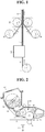
- FIG. 1 shows the case that the above-mentioned substrate for an electrochemical device on which an adhesive layer is formed is a separator.
- the apparatus for preparing an electrode assembly according to the present disclosure will be explained with reference to FIG. 1 below.
- the apparatus for preparing an electrode assembly of the present disclosure comprises a printing unit 100 including a charging mean for bringing polymer particles into electric charging to obtain electrically charged polymer particles, and a transferring mean for coating the electrically charged polymer particles by way of transferring on at least one surface of a separator 11 to form an adhesive layer 12 on the separator; and a laminating unit 200 that conducts lamination by interposing the separator 11 provided with the adhesive layer 12 between a cathode 21 and an anode 31 and applying heat and pressure thereto.
- the apparatus for preparing an electrode assembly further comprises a separator feed 10 for supplying the separator 11, a cathode feed 20 for supplying the cathode 21, and an anode feed 30 for supplying the anode 31.
- the separator 11 is supplied from the separator feed 10 to the printing unit 100, and the printing unit 100 which includes a charging mean and a transferring mean allows the formation of the adhesive layer 12 on at least one surface of the separator 11 by way of laser printing, followed by discharging.
- the charging mean includes an image carrier; a latent image-forming mean for forming an electrostatic latent image on the surface of the image carrier; a storage mean for receiving polymer particles; and a polymer particle feed for supplying the polymer particles in the surface of the image carrier so as to develop the electrostatic latent image into the polymer particles in the image carrier.
- the storage mean may further include inorganic particles disposed between the polymer particles so as to improve the fluidity of the polymer particles, and the inorganic particles may have a size of 5 to 100 nm, and examples thereof may be silica nanoparticles, but the present disclosure is not limited thereto.
- the polymer particles may be selected from the group consisting of polyvinylidene fluoride-co-hexafluoropropylene (PVDF-HFP), polyvinylidene fluoride-co-chlorotrifluoroethylene, polyvinylidene fluoride-co-trichloroethylene, polymethylmethacrylate, polybutylacrylate, polyacrylonitrile, polyvinylpyrrolidone, polyvinylacetate, polyethylene-co-vinyl acetate, polyethylene, polyethylene oxide, polyarylate, cellulose acetate, cellulose acetate butyrate, cellulose acetate propionate, cyanoethylpullulan, cyanoethylpolyvinylalcohol, cyanoethylcellulose, cyanoethylsucrose, pullulan, alginate, carboxyl methyl cellulose and a mixture thereof.
- PVDF-HFP polyvinylidene fluoride-co-ch
- the adhesive layer may be similarly formed on a cathode or an anode, in which a printing unit may be disposed to be connected with a cathode feed or an anode feed for the formation of the adhesive layer on the cathode and the anode.
- the adhesive layer is provided on the whole of one or both surface(s) of the substrate for an electrochemical device, it allows to improve adhesiveness between the separator and the electrodes while may act as a resistor in transferring lithium ions to deteriorate the performances of electrochemical devices. Therefore, in order to maintain adhesiveness and simultaneously inhibit an excessive rise in resistance, the printing unit may form an adhesive layer comprising uncoated regions in which polymer particles are not transferred on at least one surface of the substrate for an electrochemical device.
- the surface area of the uncoated regions may be 20 to 70% of the total surface area of the substrate for an electrochemical device. When such a numerical range is satisfied, suitable adhesiveness between the separator and the electrodes can be maintained and the excessive rise of resistance can be inhibited simultaneously.
- the adhesive layer may have a thickness of 0.001 to 5 ⁇ m, but the present disclosure is not limited thereto. When such a thickness range is satisfied, a resistance rise within batteries can be inhibited and suitable adhesiveness between the separator and the electrodes can be maintained simultaneously.
- the adhesive layer may be formed in a pattern that is favorable in transferring lithium ions, for example, a lattice pattern.
- the transferring mean may further include a fixing mean for settling the adhesive layer formed in the substrate for an electrochemical device, by heat and pressure.
- the fixing mean may settle the adhesive layer formed in the substrate for an electrochemical device, at a temperature of 60 to 180 °C and a pressure of 1 to 294 bar (1 to 300 kgf/cm 2 ).
- the laminating unit may conduct lamination by applying a pressure of 1 to 294 bar (1 to 300 kgf/cm2) at a temperature of 60 to 120 °C to the substrate for an electrochemical device on which the adhesive layer is applied, thereby obtaining an electrode assembly comprising a cathode, an anode and a separator interposed therebetween.
- a pressure of 1 to 294 bar (1 to 300 kgf/cm2) at a temperature of 60 to 120 °C
- the substrate for an electrochemical device on which the adhesive layer is applied thereby obtaining an electrode assembly comprising a cathode, an anode and a separator interposed therebetween.
- the separator which may be used in the present disclosure is a porous substrate
- the porous substrate may be any one which has been conventionally used in lithium secondary batteries, for example a polyolefin-based porous membrane or a non-woven fabric, but the present disclosure is not particularly limited thereto.
- the polyolefin-based porous membrane may be obtained from a polyolefin-based polymer, for example, polyethylene such as high-density polyethylene, linear low-density polyethylene, low-density polyethylene and ultra-high molecular weight polyethylene, polypropylene, polybutylene, polypentene or a mixture thereof.
- polyethylene such as high-density polyethylene, linear low-density polyethylene, low-density polyethylene and ultra-high molecular weight polyethylene, polypropylene, polybutylene, polypentene or a mixture thereof.
- non-woven fabric in addition to the polyolefin-based non-woven fabric, a non-woven fabric made of a polymer selected from polyethylene terephthalate, polybutylene terephthalate, polyester, polyacetal, polyamide, polycarbonate, polyimide, polyether ether ketone, polyether sulfone, polyphenylene oxide, polyphenylene sulfide, polyethylene naphthalate and a mixture thereof may be used.
- the non-woven fabric may be a spun-bond or melt-blown fabric consisting of long fibers in structure.
- the porous substrate has preferably a thickness of 5 to 50 ⁇ m, but is not particularly limited thereto. Also, the porous substrate has a pore size of 0.01 to 50 ⁇ m and a porosity of 10 to 95 %, but is not particularly limited thereto.
- the separator may comprise a porous substrate and a porous coating layer formed by coating inorganic particles and a polymer binder on at least one surface of the porous substrate.
- inorganic particles having a high dielectric constant may be used to increase a dissociation rate of an electrolyte salt, e.g., a lithium salt, in a liquid electrolyte, thereby improving an ionic conductivity of the electrolyte.
- an electrolyte salt e.g., a lithium salt
- the inorganic particles used in the present disclosure preferably include inorganic particles having a dielectric constant of 5 or higher, preferably 10 or higher, inorganic particles having the ability to transport lithium ions, and a mixture thereof.
- Non-limiting examples of the inorganic particles having a dielectric constant of 5 or higher include SrTiO 3 , SnO 2 , CeO 2 , MgO, NiO, CaO, ZnO, ZrO 2 , SiO 2 , Y 2 O 3 , Al 2 O 3 , AlOOH, Al(OH) 3 , TiO 2 , SiC, BaTiO 3 , Pb(Zr x , Ti 1-x )O 3 (PZT, 0 ⁇ x ⁇ 1), Pb 1-x La x Zr 1-y Ti y O 3 (PLZT, 0 ⁇ x ⁇ 1, 0 ⁇ y ⁇ 1), (1-x)Pb(Mg 1/3 Nb 2/3 )O 3 -xPbTiO 3 (PNW-PT, 0 ⁇ x ⁇ 1), HfO 2 inorganic particles and a mixture thereof.
- SrTiO 3 SnO 2 , CeO 2 , MgO, NiO, CaO, ZnO, Z
- inorganic particles such as BaTiO 3 , Pb(Zr x ,Ti 1-x )O 3 (PZT, 0 ⁇ x ⁇ 1), Pb 1-x La x Zr 1-y Ti y O 3 (PLZT, 0 ⁇ x ⁇ 1, 0 ⁇ y ⁇ 1), (1-x)Pb(Mg 1/3 Nb 2/3 )O 3 -xPbTiO 3 (PMN-PT, 0 ⁇ x ⁇ 1) and hafnia (HfO 2 ) exhibit a high dielectric characteristic of a dielectric constant of 100 or higher, as well as piezoelectricity which occurs when constant pressure is applied to induce a potential difference between both surfaces, thereby preventing the generation of internal short circuit between both electrodes due to external impact and thus further improving the safety of electrochemical devices. Also, when a mixture of inorganic particles having a high dielectric constant and inorganic particles having the ability to transport lithium ions is used, the synergetic effect thereof can be obtained.
- the inorganic particle having the ability to transport lithium ions refers to inorganic particles containing lithium atom which are capable of moving lithium ions without storing the lithium.
- the inorganic particle having the ability to transport lithium ions may transfer and move lithium ions due to a kind of defect existing in the particle structure, so it is possible to improve lithium ion conductivity in the battery and also improve the performance of the battery.
- Non-limiting examples of the inorganic particles having the ability to transport lithium ions include lithium phosphate (Li 3 PO 4 ), lithium titanium phosphate (Li x Ti y (PO 4 ) 3 , 0 ⁇ x ⁇ 2, 0 ⁇ y ⁇ 3), lithium aluminum titanium phosphate (Li x Al y Ti z (PO 4 ) 3 , 0 ⁇ x ⁇ 2, 0 ⁇ y ⁇ 1, 0 ⁇ z ⁇ 3), (LiAlTiP) x O y type glass (0 ⁇ x ⁇ 4, 0 ⁇ y ⁇ 13), lithium lanthanum titanate (Li x La y TiO 3 , 0 ⁇ x ⁇ 2, 0 ⁇ y ⁇ 3), lithium germanium thiophosphate (Li x Ge y P z S w , 0 ⁇ x ⁇ 4, 0 ⁇ y ⁇ 1, 0 ⁇ z ⁇ 1, 0 ⁇ w ⁇ 5), lithium nitride (Li x N y , 0 ⁇ x ⁇ 4, 0 ⁇ y ⁇ 2), SiS 2 type glass (
- the inorganic particles may have an average diameter of 0.001 to 100 ⁇ m, preferably 0.01 to 50 ⁇ m. When such a diameter range of the inorganic particles is satisfied, the specific surface area of the inorganic particles becomes remarkably increased to solve the problem that a binder for binding the inorganic particles is used in an excess of amounts, and also it can provide a proper thickness of the porous coating layer, a proper pore size between the inorganic particles and a proper porosity.
- the porous coating layer may have a thickness of 1 to 100 ⁇ m, preferably 1 to 40 ⁇ m, more preferably 2 to 15 ⁇ m.
- an additional transferring path of lithium ions can be further added and the impregnation of an electrolyte solution can improve to enhance the performances and thermal safety of batteries.
- the separator is interposed between the cathode 21 supplied from the cathode feed 20 and the anode 31 supplied from the anode feed 30, and fed into the laminating unit 200.
- the laminating unit 200 heat and pressure are applied to the combination of the cathode, the separator and the anode for their lamination, thereby producing an electrode assembly.
- the laminating unit 200 may comprise at least two rolls which are opposed to each other, but is not limited thereto, for example, a general laminating system may also be used.
- the printing unit 100 will be more specifically explained with reference to FIG. 2 .
- Polymer particles 108 which are placed in a developer 104 are supplied in a developing roller 105 by a feed roller 106 made of an elastic material such as polyurethane foam and sponge.
- the polymer particles 108 supplied in the developing roller 105 reach a contact part between a polymer particle-controlling blade 107 and the developing roller 105 by the rotation of the developing roller 105.
- the polymer particle-controlling blade 107 is made of an elastic material such as a metal and a rubber.
- the thin-layered polymer particles 108 are transferred into a developing section in which the polymer particles 108 are developed into the electrostatic image of a photoconductor 101 acting as an image carrier.
- the electrostatic image is formed by scanning light 103 in the photoconductor 101.
- the developing roller 105 is opposite to the photoconductor 101 at a certain interval without a contact with each other.
- the developing roller 105 rotates clockwise while the photoconductor 101 rotates anticlockwise.
- the polymer particles 108 transferred into the developing section of the photoconductor 101 are developed into the electrostatic image formed in the photoconductor 101 by electric force which is generated from a potential difference between the potential of DC voltage-overlapped AC voltage 111 that is applied by the developing roller 105 and the potential of the electrostatic image of the photoconductor 101 that is charged by a charging mean 102.
- the polymer particles 108 developed in the photoconductor 101 reach a transferring mean 109 according to the rotation direction of the photoconductor 101.
- the transferring mean 109 is applied with a reverse polarity of high voltage against the polymer particles 108 developed in the photoconductor 101. While the separator passes between such a transferring mean 109 and the photoconductor, like a corona discharger or rollers, the polymer particles 108 are transferred into the separator 11 to form an adhesive layer.
- the image of the polymer particles transferred into the separator is fused in the separator during passing through a high temperature and high pressure of fixing mean (not shown), from which the adhesive layer is fixed. Meanwhile, undeveloped polymer particles 108' remained on the developing roller 105 are recovered by a supply roller 106 which comes into contact with the developing roller 105, and undeveloped polymer particles 108' remained on the photoconductor 101 are recovered by a cleaning blade 110. Such a procedure is repeated.
- An electrode assembly prepared by the apparatus of the present disclosure comprises a cathode, an anode and a separator interposed therebetween.
- electrodes to be used as the cathode and the anode are not particularly limited, and may be manufactured by binding an electrode active material to an electrode current collector according to a conventional method known in the art.
- a cathode active material may be any of those that are commonly used in cathodes of conventional electrochemical devices.
- Non-limiting examples of the cathode active material include lithium manganese oxides, lithium cobalt oxides, lithium nickel oxides, lithium iron oxides, and lithium composite oxides thereof.
- an anode active material may be any of those that are commonly used in anodes of conventional electrochemical devices.
- Non-limiting examples of the anode active material include lithium, lithium alloys, and lithium intercalation materials such as carbon, petroleum coke, activated carbon, graphite and other carbonaceous materials.
- Non-limiting examples of a cathode current collector include aluminum foils, nickel foils and a combination thereof.
- Non-limiting examples of an anode current collector include copper foils, gold foils, nickel foils, copper alloy foils and a combination thereof.
- the electrode assembly prepared by the apparatus of the present disclosure may be in the form of general windings, as well as stack and folding according to follow-up processes, from which the final shape of lithium secondary batteries is determined.
- the electrode assembly is stored in a battery case such as a cylindrical form such as a can, a prismatic form, a pouch form, or a coin form.
- a non-aqueous electrolyte that is impregnated into the electrode assembly and comprises an electrolyte salt and an organic solvent is introduced.
- the introduction of the non-aqueous electrolyte may be carried out in any suitable step during the manufacturing of the electrochemical device depending on the manufacturing processes and desired physical properties of a final product. Specifically, the electrolyte may be introduced before assembling a battery or in the final step of the assembling.
- the electrolyte salt may be a lithium salt.
- the lithium salt may be any one which is conventionally used in an electrolyte solution for a lithium secondary battery.
- an anion of the lithium salt may be any one selected from the group consisting of F - , Cl - , Br - , I - , NO 3 - , N(CN) 2 - , BF 4 - , ClO 4 - , PF 6 - , (CF 3 ) 2 PF 4 - , (CF 3 ) 3 PF 3 - , (CF 3 ) 4 PF 2 - , (CF 3 ) 5 PF - , (CF 3 ) 6 P - , CF 3 SO 3 - , CF 3 CF 2 SO 3 - , (CF 3 SO 2 ) 2 N - , (FSO 2 ) 2 N - , CF 3 CF 2 (CF 3 ) 2 CO - , (CF 3 SO 2 ) 2 CH -
- the organic solvent used in the non-aqueous electrolyte solution may be one which is conventionally used in an electrolyte solution for a lithium secondary battery.
- an ether, an ester, an amide, a linear carbonate and a cyclic carbonate may be used alone or as a mixture of two or more.
- a linear carbonate, a cyclic carbonate, or a mixture thereof is representatively used.
- the cyclic carbonate compound may be selected from the group consisting of ethylene carbonate (EC), propylene carbonate (PC), 1,2-butylene carbonate, 2,3-butylene carbonate, 1,2-pentylene carbonate, 2,3-pentylene carbonate, vinylene carbonate, vinyl ethylene carbonate, a halide thereof and a mixture thereof.
- ethylene carbonate EC
- propylene carbonate PC
- 1,2-butylene carbonate 2,3-butylene carbonate
- 1,2-pentylene carbonate 1,2-pentylene carbonate
- 2,3-pentylene carbonate vinylene carbonate
- vinyl ethylene carbonate vinyl ethylene carbonate
- halide examples include fluoroethylene carbonate (FEC) and the like, but are not limited thereto.
- the linear carbonate compound may be any one selected from the group consisting of dimethyl carbonate (DMC), diethyl carbonate (DEC), dipropyl carbonate, ethyl methyl carbonate (EMC), methyl propyl carbonate, ethyl propyl carbonate and a mixture thereof, but is not limited thereto.
- DMC dimethyl carbonate
- DEC diethyl carbonate
- EMC ethyl methyl carbonate
- methyl propyl carbonate ethyl propyl carbonate
- ethyl propyl carbonate a mixture thereof, but is not limited thereto.
- the cyclic carbonates such as ethylene carbonate and propylene carbonate have a high viscosity and a high dielectric constant to more easily dissociate a lithium salt in an electrolyte.
- Such a cyclic carbonate may be mixed with a linear carbonate with low viscosity and low dielectric constant such as dimethyl carbonate and diethyl carbonate in a suitable ratio to provide an electrolyte solution with a high electric conductivity.
- the ether which may be used as the organic solvent is any one selected from the group consisting of dimethyl ether, diethyl ether, dipropyl ether, methyl ethyl ether, methyl propyl ether, ethyl propyl ether and a mixture thereof, but is not limited thereto.
- ester which may be used as the organic solvent is any one selected from the group consisting of methyl acetate, ethyl acetate, propyl acetate, methyl propionate, ethyl propionate, ⁇ -butyrolactone, ⁇ -valerolactone, ⁇ -caprolactone, ⁇ -valerolactone, ⁇ -caprolactone and a mixture thereof, but is not limited thereto.
- a non-woven substrate (Mitsubishi Paper Mill, LP1540) was passed from a separator feed to the printing unit, thereby printing the polymer particles on both surfaces of the non-woven substrate.
- an LMO-based cathode supplied from a cathode feed, an LTO-based anode supplied from an anode feed, and the non-woven substrate printed with the polymer particles and interposed between the cathode and the anode were passed through a laminating unit with applying a pressure of 100 kgf/cm 2 at 100 °C for their lamination, thereby obtaining an assembly.
- the assembly was put in a battery case, in which an electrolyte solution was introduced, to prepare a lithium secondary battery.
- the lithium secondary battery thus prepared was measured to have good discharge resistance of 1.25 ⁇ .
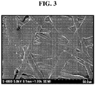
- FIG. 3 is an SEM photograph showing a surface of a separator which is disassembled from the electrode assembly.
- the lithium secondary battery prepared was measured to have a discharge resistance of 1.44 ⁇ , which is higher than that of the Example.
Landscapes
- Chemical & Material Sciences (AREA)
- Chemical Kinetics & Catalysis (AREA)
- Electrochemistry (AREA)
- General Chemical & Material Sciences (AREA)
- Engineering & Computer Science (AREA)
- Manufacturing & Machinery (AREA)
- Materials Engineering (AREA)
- Physics & Mathematics (AREA)
- Plasma & Fusion (AREA)
- Thermal Sciences (AREA)
- Cell Separators (AREA)
- Secondary Cells (AREA)
- Battery Electrode And Active Subsutance (AREA)
- Fixed Capacitors And Capacitor Manufacturing Machines (AREA)
Priority Applications (1)
| Application Number | Priority Date | Filing Date | Title |
|---|---|---|---|
| PL14740350T PL2819232T3 (pl) | 2013-01-16 | 2014-01-16 | Urządzenie do wytwarzania zespołu elektrod |
Applications Claiming Priority (2)
| Application Number | Priority Date | Filing Date | Title |
|---|---|---|---|
| KR1020130004843A KR101532730B1 (ko) | 2013-01-16 | 2013-01-16 | 전극조립체의 제조장치 |
| PCT/KR2014/000487 WO2014112812A1 (ko) | 2013-01-16 | 2014-01-16 | 전극조립체의 제조장치 |
Publications (3)
| Publication Number | Publication Date |
|---|---|
| EP2819232A1 EP2819232A1 (en) | 2014-12-31 |
| EP2819232A4 EP2819232A4 (en) | 2015-11-18 |
| EP2819232B1 true EP2819232B1 (en) | 2019-03-20 |
Family
ID=51209843
Family Applications (1)
| Application Number | Title | Priority Date | Filing Date |
|---|---|---|---|
| EP14740350.5A Active EP2819232B1 (en) | 2013-01-16 | 2014-01-16 | Apparatus for preparing electrode assembly |
Country Status (7)
| Country | Link |
|---|---|
| US (1) | US9768439B2 (pl) |
| EP (1) | EP2819232B1 (pl) |
| JP (1) | JP6327627B2 (pl) |
| KR (1) | KR101532730B1 (pl) |
| CN (1) | CN104247128B (pl) |
| PL (1) | PL2819232T3 (pl) |
| WO (1) | WO2014112812A1 (pl) |
Families Citing this family (15)
| Publication number | Priority date | Publication date | Assignee | Title |
|---|---|---|---|---|
| KR101676446B1 (ko) * | 2013-09-30 | 2016-11-15 | 주식회사 엘지화학 | 리튬 이차전지용 세퍼레이터의 제조방법, 그 방법에 의해 제조된 세퍼레이터, 및 이를 포함하는 리튬 이차전지 |
| KR101957406B1 (ko) * | 2015-03-18 | 2019-06-19 | 주식회사 엘지화학 | 일체형 전극조립체 및 이를 포함하는 전기화학소자 |
| JP6183398B2 (ja) * | 2015-03-30 | 2017-08-23 | トヨタ自動車株式会社 | 非水電解液二次電池およびその製造方法 |
| JP6500857B2 (ja) | 2016-08-09 | 2019-04-17 | トヨタ自動車株式会社 | 電極体の製造方法 |
| DE102017209960A1 (de) | 2017-06-13 | 2018-12-13 | Robert Bosch Gmbh | Verfahren zum Herstellen einer Elektrode, insbesondere für eine Batterie |
| KR102516223B1 (ko) | 2017-08-17 | 2023-03-30 | 주식회사 엘지에너지솔루션 | 전극 가열장치 및 그를 포함하는 이차전지용 제조시스템 |
| PL3557674T3 (pl) * | 2018-04-20 | 2023-11-27 | Robert Bosch Gmbh | Sposób wytwarzania zespołu elektrod dla ogniwa akumulatorowego oraz ogniwo akumulatorowe |
| CN109065843A (zh) * | 2018-07-03 | 2018-12-21 | 中国科学院金属研究所 | 一种锂离子电池负极片及其制备方法 |
| JP7180343B2 (ja) * | 2018-12-06 | 2022-11-30 | トヨタ自動車株式会社 | 電極シート製造装置 |
| US20220200038A1 (en) * | 2019-12-10 | 2022-06-23 | Lg Energy Solution, Ltd. | Unit cell, and method and apparatus for manufacturing same |
| KR102675004B1 (ko) * | 2019-12-12 | 2024-06-14 | 주식회사 엘지에너지솔루션 | 전극 조립체 제조장치와, 이를 통해 제조된 전극 조립체 및 이차전지 |
| EP4071876A4 (en) * | 2020-01-20 | 2024-03-06 | LG Energy Solution, Ltd. | SOLID-LIQUID HYBRID ELECTROLYTE MEMBRANE AND METHOD FOR THE PRODUCTION THEREOF |
| KR102822374B1 (ko) * | 2020-02-18 | 2025-06-17 | 주식회사 엘지에너지솔루션 | 리튬 이차 전지 및 이의 제조방법 |
| CN111816461B (zh) * | 2020-06-01 | 2021-05-18 | 深圳市峰泳科技有限公司 | 平面电容的覆合装置及覆合方法 |
| CN112820929B (zh) * | 2021-02-09 | 2024-06-04 | 无锡先导智能装备股份有限公司 | 叠片机 |
Citations (2)
| Publication number | Priority date | Publication date | Assignee | Title |
|---|---|---|---|---|
| EP1365461A2 (en) * | 2002-05-17 | 2003-11-26 | Nitto Denko Corporation | Adhesive composition-supporting separator for battery and electrode/separator laminate obtained by using the same |
| US20060127774A1 (en) * | 2004-10-28 | 2006-06-15 | Kim Jung H | Secondary battery and electrode plate therefor |
Family Cites Families (22)
| Publication number | Priority date | Publication date | Assignee | Title |
|---|---|---|---|---|
| WO1999031751A1 (en) * | 1997-12-18 | 1999-06-24 | Mitsubishi Denki Kabushiki Kaisha | Lithium ion secondary battery and its manufacture |
| JP4454782B2 (ja) * | 2000-04-19 | 2010-04-21 | 日本バイリーン株式会社 | 電池用セパレータの製造方法 |
| JP3745594B2 (ja) * | 2000-06-29 | 2006-02-15 | 三菱電機株式会社 | 電池及びこの電池の電極成形装置 |
| JP2003307927A (ja) * | 2002-04-16 | 2003-10-31 | Canon Inc | 画像形成装置およびプロセスカートリッジ |
| JP2004241172A (ja) * | 2003-02-04 | 2004-08-26 | Nitto Denko Corp | 電池における電極/セパレータ接合体の製造方法 |
| WO2004076079A1 (en) * | 2003-02-21 | 2004-09-10 | Virginia Commonwealth University | Electrostatic processing of electrochemical device components |
| DE112004002237B4 (de) * | 2003-11-20 | 2010-03-11 | Nissan Motor Co., Ltd., Yokohama-shi | Verfahren und Vorrichtung zur Herstellung einer Brennstoffzelle |
| JP4779307B2 (ja) * | 2004-05-20 | 2011-09-28 | 日産自動車株式会社 | 燃料電池スタックの製造方法および製造装置 |
| JP4614687B2 (ja) * | 2004-05-11 | 2011-01-19 | トヨタ自動車株式会社 | 燃料電池の電極製造装置と方法 |
| JP2007233199A (ja) * | 2006-03-02 | 2007-09-13 | Canon Inc | 現像装置 |
| US20080199781A1 (en) * | 2007-02-16 | 2008-08-21 | Michael Lunt | Method of producing an electrochemical cell and articles produced therefrom |
| JP4967749B2 (ja) * | 2007-03-28 | 2012-07-04 | セイコーエプソン株式会社 | 板金加工装置、板金加工方法、現像装置、画像形成装置 |
| JP2011216504A (ja) * | 2008-08-13 | 2011-10-27 | Nippon Zeon Co Ltd | 電気化学素子用電極の製造方法 |
| JP5719306B2 (ja) * | 2009-08-10 | 2015-05-13 | エルジー・ケム・リミテッド | リチウム二次電池 |
| US8623537B2 (en) * | 2009-08-18 | 2014-01-07 | Samsung Sdi Co., Ltd. | Rechargeable battery and battery module |
| KR20110043908A (ko) * | 2009-10-22 | 2011-04-28 | 한국에너지기술연구원 | 고분자 전해질 연료전지용 막전극접합체 제조 방법 |
| KR101055431B1 (ko) | 2009-11-23 | 2011-08-08 | 주식회사 엘지화학 | 다공성 코팅층을 구비한 분리막의 제조방법, 이로부터 형성된 분리막 및 이를 구비한 전기화학소자 |
| KR101187767B1 (ko) * | 2010-03-17 | 2012-10-05 | 주식회사 엘지화학 | 세퍼레이터 및 이를 구비한 전기화학소자 |
| KR101569136B1 (ko) * | 2012-03-05 | 2015-11-13 | 주식회사 엘지화학 | 무기입자를 이용한 리튬 이차전지용 기재의 코팅방법 및 상기 방법에 의해 코팅된 기재를 포함하는 리튬 이차전지 |
| US9248636B2 (en) * | 2012-05-01 | 2016-02-02 | Eastman Kodak Company | Forming a structural laminate that resists stress |
| WO2014046521A1 (ko) * | 2012-09-24 | 2014-03-27 | 주식회사 엘지화학 | 리튬 이차전지용 세퍼레이터의 제조방법, 그 방법에 의해 제조된 세퍼레이터, 및 이를 포함하는 리튬 이차전지 |
| US9564660B2 (en) * | 2013-06-27 | 2017-02-07 | QingHong Technology Co., Ltd. | Electric core for thin film battery |
-
2013
- 2013-01-16 KR KR1020130004843A patent/KR101532730B1/ko active Active
-
2014
- 2014-01-16 PL PL14740350T patent/PL2819232T3/pl unknown
- 2014-01-16 EP EP14740350.5A patent/EP2819232B1/en active Active
- 2014-01-16 WO PCT/KR2014/000487 patent/WO2014112812A1/ko not_active Ceased
- 2014-01-16 JP JP2015536726A patent/JP6327627B2/ja active Active
- 2014-01-16 CN CN201480001024.7A patent/CN104247128B/zh active Active
- 2014-09-11 US US14/483,469 patent/US9768439B2/en active Active
Patent Citations (2)
| Publication number | Priority date | Publication date | Assignee | Title |
|---|---|---|---|---|
| EP1365461A2 (en) * | 2002-05-17 | 2003-11-26 | Nitto Denko Corporation | Adhesive composition-supporting separator for battery and electrode/separator laminate obtained by using the same |
| US20060127774A1 (en) * | 2004-10-28 | 2006-06-15 | Kim Jung H | Secondary battery and electrode plate therefor |
Also Published As
| Publication number | Publication date |
|---|---|
| CN104247128A (zh) | 2014-12-24 |
| JP2015537337A (ja) | 2015-12-24 |
| JP6327627B2 (ja) | 2018-05-23 |
| EP2819232A4 (en) | 2015-11-18 |
| EP2819232A1 (en) | 2014-12-31 |
| KR20140092602A (ko) | 2014-07-24 |
| US20150034249A1 (en) | 2015-02-05 |
| KR101532730B1 (ko) | 2015-06-30 |
| WO2014112812A1 (ko) | 2014-07-24 |
| CN104247128B (zh) | 2017-07-11 |
| PL2819232T3 (pl) | 2019-09-30 |
| US9768439B2 (en) | 2017-09-19 |
Similar Documents
| Publication | Publication Date | Title |
|---|---|---|
| EP2819232B1 (en) | Apparatus for preparing electrode assembly | |
| EP2894694B1 (en) | Method for manufacturing separator for lithium secondary battery | |
| US10411234B2 (en) | Method of preparing separator for lithium secondary battery, separator prepared therefrom, and lithium secondary battery comprising the same | |
| EP2541643B1 (en) | Manufacturing method for separator, separator made therefrom, and manufacturing method for electrochemical device containing same | |
| US9793535B2 (en) | Electrode structure including insulating layer, manufacturing method thereof, and electrochemical device including the electrode | |
| EP2541644B1 (en) | Manufacturing method for separator | |
| KR20120108212A (ko) | 전극조립체 및 이의 제조방법 | |
| KR20130011973A (ko) | 세퍼레이터, 그 제조방법 및 이를 구비한 전기화학소자 | |
| KR102327226B1 (ko) | 전기화학소자용 분리막 및 상기 분리막을 제조하는 방법 | |
| EP2894698B1 (en) | Electrode structure including insulation layer, method for manufacturing same, and electrochemical element including same | |
| KR101521684B1 (ko) | 분리막 제조공정 및 이에 따른 분리막을 포함하는 전기화학소자 | |
| KR101028923B1 (ko) | 다공성 코팅층이 코팅된 세퍼레이터의 제조방법 | |
| KR20140029799A (ko) | 분리막의 제조공정 및 그 제조장치, 상기 분리막을 포함하는 전기화학소자 | |
| KR20170071204A (ko) | 코어-쉘 구조의 입자들을 포함하는 활성층이 구비된 전기화학 소자용 분리막 및 이의 제조방법 | |
| KR20160133276A (ko) | 전기화학소자용 분리막 및 이의 제조 방법 | |
| JP2023511212A (ja) | 電極の圧延装置及び電極の圧延方法 | |
| KR102244903B1 (ko) | 분리막 및 이의 제조방법 |
Legal Events
| Date | Code | Title | Description |
|---|---|---|---|
| PUAI | Public reference made under article 153(3) epc to a published international application that has entered the european phase |
Free format text: ORIGINAL CODE: 0009012 |
|
| 17P | Request for examination filed |
Effective date: 20140923 |
|
| AK | Designated contracting states |
Kind code of ref document: A1 Designated state(s): AL AT BE BG CH CY CZ DE DK EE ES FI FR GB GR HR HU IE IS IT LI LT LU LV MC MK MT NL NO PL PT RO RS SE SI SK SM TR |
|
| AX | Request for extension of the european patent |
Extension state: BA ME |
|
| RA4 | Supplementary search report drawn up and despatched (corrected) |
Effective date: 20151015 |
|
| RIC1 | Information provided on ipc code assigned before grant |
Ipc: H01M 10/058 20100101ALI20151009BHEP Ipc: H01M 2/16 20060101ALI20151009BHEP Ipc: H01M 4/13 20100101ALI20151009BHEP Ipc: H01M 10/04 20060101AFI20151009BHEP Ipc: H01M 10/052 20100101ALI20151009BHEP |
|
| DAX | Request for extension of the european patent (deleted) | ||
| STAA | Information on the status of an ep patent application or granted ep patent |
Free format text: STATUS: EXAMINATION IS IN PROGRESS |
|
| 17Q | First examination report despatched |
Effective date: 20170208 |
|
| REG | Reference to a national code |
Ref country code: DE Ref legal event code: R079 Ref document number: 602014043246 Country of ref document: DE Free format text: PREVIOUS MAIN CLASS: H01M0010040000 Ipc: H01M0004130000 |
|
| GRAP | Despatch of communication of intention to grant a patent |
Free format text: ORIGINAL CODE: EPIDOSNIGR1 |
|
| STAA | Information on the status of an ep patent application or granted ep patent |
Free format text: STATUS: GRANT OF PATENT IS INTENDED |
|
| RIC1 | Information provided on ipc code assigned before grant |
Ipc: H01M 4/13 20100101AFI20181001BHEP Ipc: H01M 10/052 20100101ALN20181001BHEP Ipc: H01M 10/058 20100101ALN20181001BHEP Ipc: H01M 2/16 20060101ALI20181001BHEP Ipc: H01M 10/04 20060101ALI20181001BHEP |
|
| INTG | Intention to grant announced |
Effective date: 20181024 |
|
| GRAS | Grant fee paid |
Free format text: ORIGINAL CODE: EPIDOSNIGR3 |
|
| GRAA | (expected) grant |
Free format text: ORIGINAL CODE: 0009210 |
|
| STAA | Information on the status of an ep patent application or granted ep patent |
Free format text: STATUS: THE PATENT HAS BEEN GRANTED |
|
| AK | Designated contracting states |
Kind code of ref document: B1 Designated state(s): AL AT BE BG CH CY CZ DE DK EE ES FI FR GB GR HR HU IE IS IT LI LT LU LV MC MK MT NL NO PL PT RO RS SE SI SK SM TR |
|
| REG | Reference to a national code |
Ref country code: GB Ref legal event code: FG4D |
|
| REG | Reference to a national code |
Ref country code: CH Ref legal event code: EP |
|
| REG | Reference to a national code |
Ref country code: DE Ref legal event code: R096 Ref document number: 602014043246 Country of ref document: DE |
|
| REG | Reference to a national code |
Ref country code: AT Ref legal event code: REF Ref document number: 1111423 Country of ref document: AT Kind code of ref document: T Effective date: 20190415 |
|
| REG | Reference to a national code |
Ref country code: IE Ref legal event code: FG4D |
|
| REG | Reference to a national code |
Ref country code: NL Ref legal event code: MP Effective date: 20190320 |
|
| PG25 | Lapsed in a contracting state [announced via postgrant information from national office to epo] |
Ref country code: SE Free format text: LAPSE BECAUSE OF FAILURE TO SUBMIT A TRANSLATION OF THE DESCRIPTION OR TO PAY THE FEE WITHIN THE PRESCRIBED TIME-LIMIT Effective date: 20190320 Ref country code: LT Free format text: LAPSE BECAUSE OF FAILURE TO SUBMIT A TRANSLATION OF THE DESCRIPTION OR TO PAY THE FEE WITHIN THE PRESCRIBED TIME-LIMIT Effective date: 20190320 Ref country code: FI Free format text: LAPSE BECAUSE OF FAILURE TO SUBMIT A TRANSLATION OF THE DESCRIPTION OR TO PAY THE FEE WITHIN THE PRESCRIBED TIME-LIMIT Effective date: 20190320 Ref country code: NO Free format text: LAPSE BECAUSE OF FAILURE TO SUBMIT A TRANSLATION OF THE DESCRIPTION OR TO PAY THE FEE WITHIN THE PRESCRIBED TIME-LIMIT Effective date: 20190620 |
|
| REG | Reference to a national code |
Ref country code: LT Ref legal event code: MG4D |
|
| PG25 | Lapsed in a contracting state [announced via postgrant information from national office to epo] |
Ref country code: BG Free format text: LAPSE BECAUSE OF FAILURE TO SUBMIT A TRANSLATION OF THE DESCRIPTION OR TO PAY THE FEE WITHIN THE PRESCRIBED TIME-LIMIT Effective date: 20190620 Ref country code: NL Free format text: LAPSE BECAUSE OF FAILURE TO SUBMIT A TRANSLATION OF THE DESCRIPTION OR TO PAY THE FEE WITHIN THE PRESCRIBED TIME-LIMIT Effective date: 20190320 Ref country code: RS Free format text: LAPSE BECAUSE OF FAILURE TO SUBMIT A TRANSLATION OF THE DESCRIPTION OR TO PAY THE FEE WITHIN THE PRESCRIBED TIME-LIMIT Effective date: 20190320 Ref country code: LV Free format text: LAPSE BECAUSE OF FAILURE TO SUBMIT A TRANSLATION OF THE DESCRIPTION OR TO PAY THE FEE WITHIN THE PRESCRIBED TIME-LIMIT Effective date: 20190320 Ref country code: GR Free format text: LAPSE BECAUSE OF FAILURE TO SUBMIT A TRANSLATION OF THE DESCRIPTION OR TO PAY THE FEE WITHIN THE PRESCRIBED TIME-LIMIT Effective date: 20190621 Ref country code: HR Free format text: LAPSE BECAUSE OF FAILURE TO SUBMIT A TRANSLATION OF THE DESCRIPTION OR TO PAY THE FEE WITHIN THE PRESCRIBED TIME-LIMIT Effective date: 20190320 |
|
| REG | Reference to a national code |
Ref country code: AT Ref legal event code: MK05 Ref document number: 1111423 Country of ref document: AT Kind code of ref document: T Effective date: 20190320 |
|
| PG25 | Lapsed in a contracting state [announced via postgrant information from national office to epo] |
Ref country code: IT Free format text: LAPSE BECAUSE OF FAILURE TO SUBMIT A TRANSLATION OF THE DESCRIPTION OR TO PAY THE FEE WITHIN THE PRESCRIBED TIME-LIMIT Effective date: 20190320 Ref country code: SK Free format text: LAPSE BECAUSE OF FAILURE TO SUBMIT A TRANSLATION OF THE DESCRIPTION OR TO PAY THE FEE WITHIN THE PRESCRIBED TIME-LIMIT Effective date: 20190320 Ref country code: PT Free format text: LAPSE BECAUSE OF FAILURE TO SUBMIT A TRANSLATION OF THE DESCRIPTION OR TO PAY THE FEE WITHIN THE PRESCRIBED TIME-LIMIT Effective date: 20190720 Ref country code: AL Free format text: LAPSE BECAUSE OF FAILURE TO SUBMIT A TRANSLATION OF THE DESCRIPTION OR TO PAY THE FEE WITHIN THE PRESCRIBED TIME-LIMIT Effective date: 20190320 Ref country code: EE Free format text: LAPSE BECAUSE OF FAILURE TO SUBMIT A TRANSLATION OF THE DESCRIPTION OR TO PAY THE FEE WITHIN THE PRESCRIBED TIME-LIMIT Effective date: 20190320 Ref country code: ES Free format text: LAPSE BECAUSE OF FAILURE TO SUBMIT A TRANSLATION OF THE DESCRIPTION OR TO PAY THE FEE WITHIN THE PRESCRIBED TIME-LIMIT Effective date: 20190320 Ref country code: RO Free format text: LAPSE BECAUSE OF FAILURE TO SUBMIT A TRANSLATION OF THE DESCRIPTION OR TO PAY THE FEE WITHIN THE PRESCRIBED TIME-LIMIT Effective date: 20190320 Ref country code: CZ Free format text: LAPSE BECAUSE OF FAILURE TO SUBMIT A TRANSLATION OF THE DESCRIPTION OR TO PAY THE FEE WITHIN THE PRESCRIBED TIME-LIMIT Effective date: 20190320 |
|
| PG25 | Lapsed in a contracting state [announced via postgrant information from national office to epo] |
Ref country code: SM Free format text: LAPSE BECAUSE OF FAILURE TO SUBMIT A TRANSLATION OF THE DESCRIPTION OR TO PAY THE FEE WITHIN THE PRESCRIBED TIME-LIMIT Effective date: 20190320 |
|
| PG25 | Lapsed in a contracting state [announced via postgrant information from national office to epo] |
Ref country code: IS Free format text: LAPSE BECAUSE OF FAILURE TO SUBMIT A TRANSLATION OF THE DESCRIPTION OR TO PAY THE FEE WITHIN THE PRESCRIBED TIME-LIMIT Effective date: 20190720 Ref country code: AT Free format text: LAPSE BECAUSE OF FAILURE TO SUBMIT A TRANSLATION OF THE DESCRIPTION OR TO PAY THE FEE WITHIN THE PRESCRIBED TIME-LIMIT Effective date: 20190320 |
|
| REG | Reference to a national code |
Ref country code: DE Ref legal event code: R097 Ref document number: 602014043246 Country of ref document: DE |
|
| PLBE | No opposition filed within time limit |
Free format text: ORIGINAL CODE: 0009261 |
|
| STAA | Information on the status of an ep patent application or granted ep patent |
Free format text: STATUS: NO OPPOSITION FILED WITHIN TIME LIMIT |
|
| PG25 | Lapsed in a contracting state [announced via postgrant information from national office to epo] |
Ref country code: DK Free format text: LAPSE BECAUSE OF FAILURE TO SUBMIT A TRANSLATION OF THE DESCRIPTION OR TO PAY THE FEE WITHIN THE PRESCRIBED TIME-LIMIT Effective date: 20190320 |
|
| 26N | No opposition filed |
Effective date: 20200102 |
|
| PG25 | Lapsed in a contracting state [announced via postgrant information from national office to epo] |
Ref country code: SI Free format text: LAPSE BECAUSE OF FAILURE TO SUBMIT A TRANSLATION OF THE DESCRIPTION OR TO PAY THE FEE WITHIN THE PRESCRIBED TIME-LIMIT Effective date: 20190320 |
|
| PG25 | Lapsed in a contracting state [announced via postgrant information from national office to epo] |
Ref country code: TR Free format text: LAPSE BECAUSE OF FAILURE TO SUBMIT A TRANSLATION OF THE DESCRIPTION OR TO PAY THE FEE WITHIN THE PRESCRIBED TIME-LIMIT Effective date: 20190320 |
|
| PG25 | Lapsed in a contracting state [announced via postgrant information from national office to epo] |
Ref country code: MC Free format text: LAPSE BECAUSE OF FAILURE TO SUBMIT A TRANSLATION OF THE DESCRIPTION OR TO PAY THE FEE WITHIN THE PRESCRIBED TIME-LIMIT Effective date: 20190320 |
|
| REG | Reference to a national code |
Ref country code: CH Ref legal event code: PL |
|
| REG | Reference to a national code |
Ref country code: BE Ref legal event code: MM Effective date: 20200131 |
|
| PG25 | Lapsed in a contracting state [announced via postgrant information from national office to epo] |
Ref country code: LU Free format text: LAPSE BECAUSE OF NON-PAYMENT OF DUE FEES Effective date: 20200116 |
|
| PG25 | Lapsed in a contracting state [announced via postgrant information from national office to epo] |
Ref country code: BE Free format text: LAPSE BECAUSE OF NON-PAYMENT OF DUE FEES Effective date: 20200131 Ref country code: LI Free format text: LAPSE BECAUSE OF NON-PAYMENT OF DUE FEES Effective date: 20200131 Ref country code: CH Free format text: LAPSE BECAUSE OF NON-PAYMENT OF DUE FEES Effective date: 20200131 |
|
| PG25 | Lapsed in a contracting state [announced via postgrant information from national office to epo] |
Ref country code: IE Free format text: LAPSE BECAUSE OF NON-PAYMENT OF DUE FEES Effective date: 20200116 |
|
| PG25 | Lapsed in a contracting state [announced via postgrant information from national office to epo] |
Ref country code: MT Free format text: LAPSE BECAUSE OF FAILURE TO SUBMIT A TRANSLATION OF THE DESCRIPTION OR TO PAY THE FEE WITHIN THE PRESCRIBED TIME-LIMIT Effective date: 20190320 Ref country code: CY Free format text: LAPSE BECAUSE OF FAILURE TO SUBMIT A TRANSLATION OF THE DESCRIPTION OR TO PAY THE FEE WITHIN THE PRESCRIBED TIME-LIMIT Effective date: 20190320 |
|
| PG25 | Lapsed in a contracting state [announced via postgrant information from national office to epo] |
Ref country code: MK Free format text: LAPSE BECAUSE OF FAILURE TO SUBMIT A TRANSLATION OF THE DESCRIPTION OR TO PAY THE FEE WITHIN THE PRESCRIBED TIME-LIMIT Effective date: 20190320 |
|
| P01 | Opt-out of the competence of the unified patent court (upc) registered |
Effective date: 20230323 |
|
| P02 | Opt-out of the competence of the unified patent court (upc) changed |
Effective date: 20230411 |
|
| REG | Reference to a national code |
Ref country code: DE Ref legal event code: R081 Ref document number: 602014043246 Country of ref document: DE Owner name: LG ENERGY SOLUTION, LTD., KR Free format text: FORMER OWNER: LG CHEM, LTD., SEOUL, KR |
|
| REG | Reference to a national code |
Ref country code: GB Ref legal event code: 732E Free format text: REGISTERED BETWEEN 20230824 AND 20230831 |
|
| PGFP | Annual fee paid to national office [announced via postgrant information from national office to epo] |
Ref country code: PL Payment date: 20241224 Year of fee payment: 12 |
|
| PGFP | Annual fee paid to national office [announced via postgrant information from national office to epo] |
Ref country code: GB Payment date: 20241223 Year of fee payment: 12 |
|
| PGFP | Annual fee paid to national office [announced via postgrant information from national office to epo] |
Ref country code: FR Payment date: 20241224 Year of fee payment: 12 |
|
| PGFP | Annual fee paid to national office [announced via postgrant information from national office to epo] |
Ref country code: DE Payment date: 20241223 Year of fee payment: 12 |