EP2805384B1 - Connecteur électrique - Google Patents
Connecteur électrique Download PDFInfo
- Publication number
- EP2805384B1 EP2805384B1 EP12821320.4A EP12821320A EP2805384B1 EP 2805384 B1 EP2805384 B1 EP 2805384B1 EP 12821320 A EP12821320 A EP 12821320A EP 2805384 B1 EP2805384 B1 EP 2805384B1
- Authority
- EP
- European Patent Office
- Prior art keywords
- connector
- lock
- latch
- fitting
- arm
- Prior art date
- Legal status (The legal status is an assumption and is not a legal conclusion. Google has not performed a legal analysis and makes no representation as to the accuracy of the status listed.)
- Active
Links
- 210000000078 claw Anatomy 0.000 claims description 92
- 230000000694 effects Effects 0.000 description 2
- 230000001681 protective effect Effects 0.000 description 2
- 230000011664 signaling Effects 0.000 description 2
- 239000002131 composite material Substances 0.000 description 1
- 230000008602 contraction Effects 0.000 description 1
- 238000000034 method Methods 0.000 description 1
- 238000000926 separation method Methods 0.000 description 1
Images


Classifications
-
- H—ELECTRICITY
- H01—ELECTRIC ELEMENTS
- H01R—ELECTRICALLY-CONDUCTIVE CONNECTIONS; STRUCTURAL ASSOCIATIONS OF A PLURALITY OF MUTUALLY-INSULATED ELECTRICAL CONNECTING ELEMENTS; COUPLING DEVICES; CURRENT COLLECTORS
- H01R13/00—Details of coupling devices of the kinds covered by groups H01R12/70 or H01R24/00 - H01R33/00
- H01R13/62—Means for facilitating engagement or disengagement of coupling parts or for holding them in engagement
- H01R13/627—Snap or like fastening
- H01R13/6271—Latching means integral with the housing
- H01R13/6273—Latching means integral with the housing comprising two latching arms
-
- B—PERFORMING OPERATIONS; TRANSPORTING
- B60—VEHICLES IN GENERAL
- B60L—PROPULSION OF ELECTRICALLY-PROPELLED VEHICLES; SUPPLYING ELECTRIC POWER FOR AUXILIARY EQUIPMENT OF ELECTRICALLY-PROPELLED VEHICLES; ELECTRODYNAMIC BRAKE SYSTEMS FOR VEHICLES IN GENERAL; MAGNETIC SUSPENSION OR LEVITATION FOR VEHICLES; MONITORING OPERATING VARIABLES OF ELECTRICALLY-PROPELLED VEHICLES; ELECTRIC SAFETY DEVICES FOR ELECTRICALLY-PROPELLED VEHICLES
- B60L53/00—Methods of charging batteries, specially adapted for electric vehicles; Charging stations or on-board charging equipment therefor; Exchange of energy storage elements in electric vehicles
- B60L53/10—Methods of charging batteries, specially adapted for electric vehicles; Charging stations or on-board charging equipment therefor; Exchange of energy storage elements in electric vehicles characterised by the energy transfer between the charging station and the vehicle
- B60L53/14—Conductive energy transfer
- B60L53/16—Connectors, e.g. plugs or sockets, specially adapted for charging electric vehicles
-
- H—ELECTRICITY
- H01—ELECTRIC ELEMENTS
- H01R—ELECTRICALLY-CONDUCTIVE CONNECTIONS; STRUCTURAL ASSOCIATIONS OF A PLURALITY OF MUTUALLY-INSULATED ELECTRICAL CONNECTING ELEMENTS; COUPLING DEVICES; CURRENT COLLECTORS
- H01R13/00—Details of coupling devices of the kinds covered by groups H01R12/70 or H01R24/00 - H01R33/00
- H01R13/62—Means for facilitating engagement or disengagement of coupling parts or for holding them in engagement
- H01R13/627—Snap or like fastening
- H01R13/6275—Latching arms not integral with the housing
-
- H—ELECTRICITY
- H01—ELECTRIC ELEMENTS
- H01R—ELECTRICALLY-CONDUCTIVE CONNECTIONS; STRUCTURAL ASSOCIATIONS OF A PLURALITY OF MUTUALLY-INSULATED ELECTRICAL CONNECTING ELEMENTS; COUPLING DEVICES; CURRENT COLLECTORS
- H01R13/00—Details of coupling devices of the kinds covered by groups H01R12/70 or H01R24/00 - H01R33/00
- H01R13/62—Means for facilitating engagement or disengagement of coupling parts or for holding them in engagement
- H01R13/629—Additional means for facilitating engagement or disengagement of coupling parts, e.g. aligning or guiding means, levers, gas pressure electrical locking indicators, manufacturing tolerances
- H01R13/633—Additional means for facilitating engagement or disengagement of coupling parts, e.g. aligning or guiding means, levers, gas pressure electrical locking indicators, manufacturing tolerances for disengagement only
-
- H—ELECTRICITY
- H01—ELECTRIC ELEMENTS
- H01R—ELECTRICALLY-CONDUCTIVE CONNECTIONS; STRUCTURAL ASSOCIATIONS OF A PLURALITY OF MUTUALLY-INSULATED ELECTRICAL CONNECTING ELEMENTS; COUPLING DEVICES; CURRENT COLLECTORS
- H01R13/00—Details of coupling devices of the kinds covered by groups H01R12/70 or H01R24/00 - H01R33/00
- H01R13/64—Means for preventing incorrect coupling
- H01R13/641—Means for preventing incorrect coupling by indicating incorrect coupling; by indicating correct or full engagement
-
- B—PERFORMING OPERATIONS; TRANSPORTING
- B60—VEHICLES IN GENERAL
- B60L—PROPULSION OF ELECTRICALLY-PROPELLED VEHICLES; SUPPLYING ELECTRIC POWER FOR AUXILIARY EQUIPMENT OF ELECTRICALLY-PROPELLED VEHICLES; ELECTRODYNAMIC BRAKE SYSTEMS FOR VEHICLES IN GENERAL; MAGNETIC SUSPENSION OR LEVITATION FOR VEHICLES; MONITORING OPERATING VARIABLES OF ELECTRICALLY-PROPELLED VEHICLES; ELECTRIC SAFETY DEVICES FOR ELECTRICALLY-PROPELLED VEHICLES
- B60L2270/00—Problem solutions or means not otherwise provided for
- B60L2270/30—Preventing theft during charging
- B60L2270/32—Preventing theft during charging of electricity
-
- B—PERFORMING OPERATIONS; TRANSPORTING
- B60—VEHICLES IN GENERAL
- B60L—PROPULSION OF ELECTRICALLY-PROPELLED VEHICLES; SUPPLYING ELECTRIC POWER FOR AUXILIARY EQUIPMENT OF ELECTRICALLY-PROPELLED VEHICLES; ELECTRODYNAMIC BRAKE SYSTEMS FOR VEHICLES IN GENERAL; MAGNETIC SUSPENSION OR LEVITATION FOR VEHICLES; MONITORING OPERATING VARIABLES OF ELECTRICALLY-PROPELLED VEHICLES; ELECTRIC SAFETY DEVICES FOR ELECTRICALLY-PROPELLED VEHICLES
- B60L2270/00—Problem solutions or means not otherwise provided for
- B60L2270/30—Preventing theft during charging
- B60L2270/34—Preventing theft during charging of parts
-
- Y—GENERAL TAGGING OF NEW TECHNOLOGICAL DEVELOPMENTS; GENERAL TAGGING OF CROSS-SECTIONAL TECHNOLOGIES SPANNING OVER SEVERAL SECTIONS OF THE IPC; TECHNICAL SUBJECTS COVERED BY FORMER USPC CROSS-REFERENCE ART COLLECTIONS [XRACs] AND DIGESTS
- Y02—TECHNOLOGIES OR APPLICATIONS FOR MITIGATION OR ADAPTATION AGAINST CLIMATE CHANGE
- Y02T—CLIMATE CHANGE MITIGATION TECHNOLOGIES RELATED TO TRANSPORTATION
- Y02T10/00—Road transport of goods or passengers
- Y02T10/60—Other road transportation technologies with climate change mitigation effect
- Y02T10/70—Energy storage systems for electromobility, e.g. batteries
-
- Y—GENERAL TAGGING OF NEW TECHNOLOGICAL DEVELOPMENTS; GENERAL TAGGING OF CROSS-SECTIONAL TECHNOLOGIES SPANNING OVER SEVERAL SECTIONS OF THE IPC; TECHNICAL SUBJECTS COVERED BY FORMER USPC CROSS-REFERENCE ART COLLECTIONS [XRACs] AND DIGESTS
- Y02—TECHNOLOGIES OR APPLICATIONS FOR MITIGATION OR ADAPTATION AGAINST CLIMATE CHANGE
- Y02T—CLIMATE CHANGE MITIGATION TECHNOLOGIES RELATED TO TRANSPORTATION
- Y02T10/00—Road transport of goods or passengers
- Y02T10/60—Other road transportation technologies with climate change mitigation effect
- Y02T10/7072—Electromobility specific charging systems or methods for batteries, ultracapacitors, supercapacitors or double-layer capacitors
-
- Y—GENERAL TAGGING OF NEW TECHNOLOGICAL DEVELOPMENTS; GENERAL TAGGING OF CROSS-SECTIONAL TECHNOLOGIES SPANNING OVER SEVERAL SECTIONS OF THE IPC; TECHNICAL SUBJECTS COVERED BY FORMER USPC CROSS-REFERENCE ART COLLECTIONS [XRACs] AND DIGESTS
- Y02—TECHNOLOGIES OR APPLICATIONS FOR MITIGATION OR ADAPTATION AGAINST CLIMATE CHANGE
- Y02T—CLIMATE CHANGE MITIGATION TECHNOLOGIES RELATED TO TRANSPORTATION
- Y02T90/00—Enabling technologies or technologies with a potential or indirect contribution to GHG emissions mitigation
- Y02T90/10—Technologies relating to charging of electric vehicles
- Y02T90/14—Plug-in electric vehicles
Definitions
- the electric wire W connected to the power feeding terminal 211 inside the connector fitting portion 210 extends through a handle portion 221 to the outside, and a slide portion 230 absorbing an expansion/contraction according to a slide operation of the power feeding terminal 211, the electric wire W, or the like is provided between the connector fitting portion 210 and the handle portion 221.
- the battery may be charged while the power receiving connector 300 and the connector fitting portion 210 are in a state of half-fitting together.
- An electrical connector in accordance with some embodiments includes: a connector case including a connector fitting portion configured to fit to a power receiving connector and accommodating an electric wire; a power feeding terminal provided in the connector fitting portion and connected to the electric wire, the power feeding terminal being configured to be connected to a power receiving terminal of the power receiving connector in a fitting state where the power receiving connector and the connector fitting portion are fitted together; a lock mechanism configured to prevent the power receiving connector and the connector fitting portion from being separated from each other in the fitting state between the power receiving connector and the connector fitting portion; a fitting detecting mechanism configured to detect the fitting state between the power receiving connector and the connector fitting portion; and a lock release unit including an operating portion advanceable from and retractable to the connector case, and a latch portion configured to latch to a portion of the lock mechanism and a portion of the fitting detecting mechanism with the operating portion being retracted to the connector case.
- the lock mechanism includes a first lock unit including a lock arm swingably provided in the connector case, and a lock claw provided at one end of the lock arm at a side of the power receiving connector and being protrudable and retractable from the connector fitting portion, and a second lock unit including an auxiliary arm connected to the lock arm, and an auxiliary latch piece provided at an end of the auxiliary arm and configured to latch to the latch portion of the lock release unit.
- the first lock unit may include a lock piece provided at the other end of the lock arm and being latchable to the latch portion of the lock release unit.
- the lock piece may be provided at a position facing the auxiliary latch piece.
- the electrical connector 100 is fittable to a power receiving connector 10 provided with a power receiving terminal 11A (see Fig. 4 ) used for power feeding, and includes a power feeding terminal 111A that is connected to the power receiving terminal 11A when the electrical connector 100 is in a state of fitting to the power receiving connector 10.
- the power receiving connector 10 includes a connector housing 11 that accommodates the power receiving terminal 11A and a signal terminal 11B for a control circuit such as signaling/ displaying, and a hood portion 12 that is integrated with the connector housing 11 and has an inner periphery that fits to a front end of the electrical connector 100 (an outer periphery of a connector fitting portion 111).
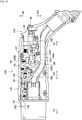
- a lock chamber 114 accommodating the lock mechanism 120, the fitting detecting mechanism 130, and the lock release unit 140 is provided over the electric wire W in the connector case 110.
- a handle portion 115 held by an operator is provided at a rear bottom of the connector case 110, and the electric wire W extends through the handle portion 115 to the outside.
- the first lock unit 120A includes a biforked lock arm 121 that is swingably provided in the connector case 110, a lock claw 122 ( Figs. 2 , 4 and 5 ) that is provided at one end of the lock arm 121 on a power receiving connector 10 side and is protrudable/retractable from an outer periphery of the connector fitting portion 111, and a lock piece 123 that is provided at the other end of the lock arm 121 and is latchable to a latch groove portion 143 of the lock release unit 140.
- the lock arm 121 is bent at the side of the lock claw 122 from the lock arm shaft 124 in a width direction WD perpendicular to a fitting/separating direction FSD (see Figs. 8 to 10 ).
- the lock arm 121 is bent in a bottom direction BD at the position of the lock arm shaft 124, and the lock piece 123 extends from the bent front end in the fitting/ separating direction FSD (see Figs. 5 and 8 to 10 ).
- the lock piece 123 extends in the top direction TD, and is latchable to the latch groove portion 143 (first latch groove portion 143A) of the lock release unit 140.
- the lock piece 123 is provided at a position facing a latch piece 133 of the fitting detecting mechanism 130, which will be described later.
- An air gap 123A (see Figs. 8 to 10 ) opening in the width direction WD perpendicular to the fitting/separating direction FSD is provided between the lock piece 123 and the lock arm 121.
- the lock arm 121 swings, so that the lock piece 123 latches to the latch groove portion 143 (first latch groove portion 143A) of the lock release unit 140. While the lock claw 122 is in a state of protruding from the connector fitting portion 111, the lock arm 121 swings, so that the latching of the lock piece 123 to the latch groove portion 143 of the lock release unit 140 is released.
- the latch piece 133 is provided on the nearer side than the lock claw 122 in the fitting direction of the connector fitting portion 111 to the power receiving connector 10. While the latch claw 132 is in a state of retracting into the connector fitting portion 111, the latch arm 131 swings, so that the latching of the latch piece 133 to the latch groove portion 143 (second latch groove portion 143B) of the lock release unit 140 is released.
- the micro switch 151 does not flow a current from the electrical connector 100 to the power receiving connector 10 when the micro switch 151 is not in a state of being abutted by a portion (movable shaft 153 to be described below) of the solenoid 152.
- the solenoid 152 includes a movable shaft 153 that moves in the width direction WD when the power receiving connector 10 and the connector fitting portion 111 change from a half-fitting state to a fitting state, and a regulation arm 154 (see Figs. 9 and 10 ) that moves according to the movement of the movable shaft 153.
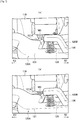
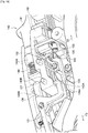
- FIGS. 16 to 26 are views for describing an operation of the electrical connector 100 according to the present embodiment.
- the electrical connector 100 charges a battery (not illustrated) mounted on a vehicle such as an electric vehicle (EV) or a hybrid electric vehicle (HEV) according to information (instruction) from a power supply unit (not illustrated) connected to an end portion of the electric wire W extending from the handle portion 115 to the outside, when being in a state of fitting to the power receiving connector 10.
- a battery not illustrated mounted on a vehicle such as an electric vehicle (EV) or a hybrid electric vehicle (HEV) according to information (instruction) from a power supply unit (not illustrated) connected to an end portion of the electric wire W extending from the handle portion 115 to the outside, when being in a state of fitting to the power receiving connector 10.
- the release switch 141 moves toward the separating direction SD because all the latching to the latch groove portion 143 is released. Accordingly, the regulation wall surface 145 of the lock release unit 140 located between the micro switch 151 and the movable shaft 153 moves to the separating direction SD side. Then, as illustrated in Fig. 22 , the movable shaft 153 of the power feedability determining mechanism 150 protrudes along the width direction WD and presses the micro switch 151, thereby becoming a chargeable state.
- the regulation arm 154 is inserted into the air gap 123A of the lock arm 121 (see Fig. 10 ). Therefore, even when the release switch 141 is about to be moved in the fitting direction FD, the swing of the lock arm 121 can be prevented, so that the removal of the lock claw 122 from the connector housing 11 can be prevented.
- the fitting of the power receiving connector 10 and the connector fitting portion 111 can be prevented from being accidentally released when charging the battery (not illustrated) mounted on the vehicle.
- the movable shaft 153 of the solenoid 152 returns to the original state, so that the abutting between the micro switch 151 and the movable shaft 153 is released (see Fig. 13 ). Then, a gap occurs between the micro switch 151 and the movable shaft 153, and the regulation arm 154 retracts from the air gap 123A of the lock arm 121 (see Fig. 9 ). Accordingly, the lock release unit 140 is movable along the fitting direction FD.
- the latch arm 131 swings and the latch claw 132 protrudes from the cutout 116 of the connector fitting portion 111, so that the latch piece 133 is latched to the second latch groove portion 143B of the lock release unit 140.
- the protrusion 131A of the latch arm 131 swings the hold arm 161 such that the fitting direction FD side is located in the bottom direction BD to be lower than the hold arm shaft 163 of the hold arm 161. Accordingly, the hold latch piece 162 of the release switch hold portion 160 removes from the second latch groove portion 143B of the lock release unit 140.
- the lock claw 122 protrudes from the cutout 116 of the connector fitting portion 111 (see Fig. 16 ).
- the lock piece 123 removes from the first latch groove portion 143A of the lock release unit 140, and the auxiliary latch piece 127 is in a state of being latchable to the second latch groove portion 143B of the lock release unit 140.
- the lock claw 122 while the lock claw 122 is in a state of retracting into the connector fitting portion 111, the lock arm 121 and the auxiliary arm 126 swing, so that the latching of the auxiliary latch piece 127 to the second latch groove portion 143B is released.
- the latch claw 132 is provided on the nearer side than the lock claw 122 in the fitting direction FD of the connector fitting portion 111 to the power receiving connector 10. While the latch claw 132 is in a state of retracting into the connector fitting portion 111, the latch arm 131 swings, so that the latching between the latch piece 133 and the second latch groove portion 143B is released.
- the latch claw 132 is retracted into the connector fitting portion 111 by the abutting on the hood portion 12 of the power receiving connector 10 to be later than the lock claw 122. Therefore, the latching between the latch piece 133 and the second latch groove portion 143B by the swing of the latch claw 132 is not released unless the latching between the auxiliary latch piece 127 and the second latch groove portion 143B by the swing of the auxiliary arm 126 is released.
- the power receiving connector 10 and the connector fitting portion 111 are not in a state of completely fitting together, and thus the release switch 141 does not protrude from the connector case 110 and is yet unoperatable.
- the latching between the lock piece 123 or the auxiliary latch piece 127 and the latch groove portion 143 is released and also the latching between the latch piece 133 and the second latch groove portion 143B is released, the power receiving connector 10 and the connector fitting portion 111 are in a state of completely fitting together, and thus the release switch 141 protrudes from the connector case 110 and is operatable. Accordingly, the fitting state between the power receiving connector 10 and the connector fitting portion 111 can be detected according to the positional state of the release switch 141. Therefore, the battery can be prevented from being charged in the half-fitting state, thus making it possible to improve stability more securely.
- the latch claw 132 is provided with the lock claw 122 along the fitting direction FD. Accordingly, for example, when the connector housing 11 or the hood portion 12 of the power receiving connector 10 is damaged, even when the lock claw 122 does not abut the hood portion 12 of the power receiving connector 10 and only the latch claw 132 abuts the hood portion 12 and is retracted into the connector fitting portion 111, the latching between the lock piece 123 or the auxiliary latch piece 127 and the latch groove portion 143 is not released.
- the release switch 141 does not protrude from the connector case 110 and can be made unoperatable.
- the lock piece 123 is provided at a position facing the auxiliary latch piece 127. Accordingly, the lock piece 123 and the auxiliary latch piece 127 can be latched to the latch groove portion 143 (first latch groove portion 143A and second latch groove portion 143B) of the lock release unit 140, thus making it possible to provide double locking. Therefore, even when the latching between the auxiliary latch piece 127 and the second latch groove portion 143B is released, the release switch 141 does not protrude from the connector case 110 and is unoperatable until the latching between the lock piece 123 and the first latch groove portion 143A is released. Accordingly, the abrupt protrusion of the release switch 141 from the connector case 110 can be securely prevented.
- the width W2 of the latch claw 132 is smaller than the width W1 of the lock claw 122. Accordingly, it is possible to prevent the case where the lock claw 122 is not retracted into the connector fitting portion 111 and only the latch claw 132 is abruptly retracted into the connector fitting portion 111.
- the regulation wall surface 145 is provided under the release body portion 142, and is movable in the fitting/separating direction FSD between the micro switch 151 and the movable shaft 153 of the power feedability determining mechanism 150. Accordingly, when the release switch 141 protrudes from the connector case 110 and is operatable, the regulation wall surface 145 retracts from the portion between the micro switch 151 and the movable shaft 153. Therefore, unless the power receiving connector 10 and the connector fitting portion 111 are not completely fitted together, the micro switch 151 is not turned on, and the battery can be prevented from being charged.
- the release switch 141 can be prevented from moving in the fitting direction FD, so that the operation of the release switch 141 can be prevented. That is, in the charge mode, the lock claw 122 can be prevented from being removed and released from the power receiving connector 10, so that the power receiving connector 10 and the connector fitting portion 111 can be prevented from be separated from each other due to a fitting error thereof.
- the regulation arm 154 is insertable/extractable into/from the air gap 123A of the lock arm 121 according to the movement of the movable shaft 153, and is inserted into the air gap 123A to regulate the swing of the lock arm 121. Accordingly, the lock arm 121 does not swing when the lock claw 122 is in a state of protruding from the connector fitting portion 111. Therefore, the fitting of the power receiving connector 10 and the connector fitting portion 111 can be prevented from be accidentally released during charging.
- the electrical connector 100 further includes the release switch hold portion 160 that holds the position of the lock release unit 140 while the release switch 141 is in a state of being pressed. Accordingly, even when the release switch 141 is not continuously pressed in the fitting direction FD, the release switch 141 does not protrude from the connector case 110 and can be held in an unoperatable state. Accordingly, the operability is improved because an operator need not perform the operation while pressing the release switch 141.
- the latch arm 131 includes the protrusion 131A that releases the latching between the hold latch piece 162 and the second latch groove portion 143B when the latch piece 133 and the second latch groove portion 143B are latched together. That is, while the release switch 141 does not protrude from the connector case 110, the latching between the hold latch piece 162 and the second latch groove portion 143B is released and the latch piece 133 and the second latch groove portion 143B are latched together. Therefore, the release switch 141 can be prevented from protruding from the connector case 110 accidentally when the connector fitting portion 111 is separated from the power receiving connector 10.
- the embodiments of the present invention may be changed as follows.
- the electrical connector 100 has been described as a connector charging a battery (not illustrated) mounted on a vehicle such as an electric vehicle (EV) or a hybrid electric vehicle (HEV), the present invention is not limited thereto.
- the electrical connector 100 may be used to charge other batteries.
- the respective arms have been described as being biased by coil springs as bias members, the present invention is not limited thereto.
- the respective arms may be biased by other springs, cylinders, or the like.
- the respective configurations of the electrical connector 100 are not limited to the description in the present embodiment, and may be any other configurations that can be implemented.
- the electrical connector 100 includes at least the connector case 110, the lock mechanism 120, the fitting detecting mechanism 130, and the lock release unit 140.
- the electrical connector 100 may not include the power feedability determining mechanism 150 and the release switch hold portion 160.
Claims (4)
- Connecteur électrique (100) comprenant :un boîtier de connecteur (110) comprenant une portion de montage de connecteur (111) configurée pour être montée sur un connecteur de réception de puissance (10) et logeant un fil électrique (W) ;une borne d'alimentation en puissance (111A) prévue dans la portion de montage de connecteur (111) et connectée au fil électrique (W), la borne d'alimentation en puissance (111A) étant configurée pour être connectée à une borne de réception de puissance (11A) du connecteur de réception de puissance (10) dans un état de montage où le connecteur de réception de puissance (10) et la portion de montage de connecteur (111) sont montés ensemble ;un mécanisme de verrouillage (120) configuré pour empêcher le connecteur de réception de puissance (10) et la portion de montage de connecteur (111) d'être séparés l'un de l'autre dans l'état de montage entre le connecteur de réception de puissance (10) et la portion de montage de connecteur (111) ;un mécanisme de détection de montage (130) configuré pour détecter l'état de montage entre le connecteur de réception de puissance (10) et la portion de montage de connecteur (111) ; etune unité de déverrouillage (140) comprenant une portion de commande (141) pouvant être avancée à partir du boîtier de connecteur (110) et rétractée vers celui-ci, et une portion d'enclenchement (143, 143B) configurée pour s'enclencher avec une portion du mécanisme de verrouillage (120) et une portion du mécanisme de détection de montage (130) avec la portion de commande (141) qui est rétractée vers le boîtier de connecteur (110),dans lequel, lors de la libération de l'enclenchement de la portion d'enclenchement (143, 143B) dans l'état de montage entre le connecteur de réception de puissance (10) et la portion de montage de connecteur (111), la portion de commande (141) de l'unité de déverrouillage (140) est configurée pour se déplacer dans une direction où la portion de commande (141) avance à partir du boîtier de connecteur (110) et devient utilisable pour permettre de défaire l'état de montage entre le connecteur de réception de puissance (10) et la portion de montage de connecteur (111),dans lequel le mécanisme de verrouillage (120) comprend une première unité de verrouillage (120A) comprenantun bras de verrouillage (121) prévu de manière oscillante dans le boîtier de connecteur (110), etune griffe de verrouillage (122) prévue à une extrémité du bras de verrouillage (121) au niveau d'un côté du connecteur de réception de puissance (10) et pouvant faire saillie et être rétractée de la portion de montage de connecteur (111), etcaractérisé en ce que le mécanisme de verrouillage comprend en outre :une deuxième unité de verrouillage (120B) comprenantun bras auxiliaire (126) connecté au bras de verrouillage (121), etune pièce d'enclenchement auxiliaire (127) prévue à une extrémité du bras auxiliaire (126) et configurée pour s'enclencher avec la portion d'enclenchement (143, 143B) de l'unité de déverrouillage (140),dans lequel l'enclenchement de la pièce d'enclenchement auxiliaire (127) avec la portion d'enclenchement (143, 143B) de l'unité de déverrouillage (140) est défait avec la griffe de verrouillage (122) qui est rétractée dans la portion de montage de connecteur (111) par une oscillation du bras de verrouillage (121) et du bras auxiliaire (126),dans lequel le mécanisme de détection de montage (130) comprendun bras d'enclenchement (131) prévu de manière oscillante dans le boîtier de connecteur (110),une griffe d'enclenchement (132) prévue à une extrémité du bras d'enclenchement (131) au niveau d'un côté du connecteur de réception de puissance (10) et pouvant faire saillie et être rétractée de la portion de montage de connecteur (111), etune pièce d'enclenchement (133) prévue à l'autre extrémité du bras d'enclenchement (131) et pouvant être enclenchée avec la portion d'enclenchement (143, 143B) de l'unité de déverrouillage (143),dans lequel la griffe d'enclenchement (132) est prévue au niveau d'un côté plus proche que la griffe de verrouillage (122) dans une direction de montage où la portion de montage de connecteur (111) est montée sur le connecteur de réception de puissance (10), etdans lequel l'enclenchement de la pièce d'enclenchement (133) avec la portion d'enclenchement (143, 143B) de l'unité de déverrouillage (140) est défait avec la griffe d'enclenchement (132) qui est rétractée dans la portion de montage de connecteur (111) par une oscillation du bras d'enclenchement (131).
- Connecteur électrique (100) selon la revendication 1, dans lequel la griffe d'enclenchement (132) est dotée de la griffe de verrouillage (122) le long de la direction de montage.
- Connecteur électrique (100) selon la revendication 1 ou 2, dans lequel
la première unité de verrouillage (120A) comprend une pièce de verrouillage (123) prévue à l'autre extrémité du bras de verrouillage (121) et qui peut être enclenchée avec la portion d'enclenchement (143, 143B) de l'unité de déverrouillage (140), et
la pièce de verrouillage (123) est prévue au niveau d'une position faisant face à la pièce d'enclenchement auxiliaire (127). - Connecteur électrique (100) selon l'une quelconque des revendications 1 à 3, dans lequel
la première unité de verrouillage (120A) comprend
une tige de bras de verrouillage (124) configurée pour supporter de manière pivotante le bras de verrouillage (121) pour qu'il puisse osciller, et
un élément d'inclinaison de bras de verrouillage (125) configuré pour incliner le bras de verrouillage (121) dans une direction où la griffe de verrouillage (122) fait saillie de la portion de montage de connecteur (111),
le mécanisme de détection de montage (130) comprend
une tige de bras d'enclenchement (134) configurée pour supporter de manière pivotante le bras d'enclenchement (131) pour qu'il puisse osciller, et
un élément d'inclinaison de bras d'enclenchement (135) configuré pour incliner le bras d'enclenchement (131) dans une direction où la griffe d'enclenchement (132) fait saillie de la portion de montage de connecteur (111), et
l'unité de déverrouillage (140) comprend un élément d'inclinaison de déverrouillage (144) configuré pour incliner l'unité de déverrouillage (140) dans la direction où la portion de commande (141) avance à partir du boîtier de connecteur (110).
Applications Claiming Priority (2)
| Application Number | Priority Date | Filing Date | Title |
|---|---|---|---|
| JP2012007302A JP5798935B2 (ja) | 2012-01-17 | 2012-01-17 | 電気コネクタ |
| PCT/JP2012/008120 WO2013108340A1 (fr) | 2012-01-17 | 2012-12-19 | Connecteur électrique |
Publications (2)
| Publication Number | Publication Date |
|---|---|
| EP2805384A1 EP2805384A1 (fr) | 2014-11-26 |
| EP2805384B1 true EP2805384B1 (fr) | 2018-01-24 |
Family
ID=47666439
Family Applications (1)
| Application Number | Title | Priority Date | Filing Date |
|---|---|---|---|
| EP12821320.4A Active EP2805384B1 (fr) | 2012-01-17 | 2012-12-19 | Connecteur électrique |
Country Status (5)
| Country | Link |
|---|---|
| US (1) | US9106015B2 (fr) |
| EP (1) | EP2805384B1 (fr) |
| JP (1) | JP5798935B2 (fr) |
| CN (1) | CN104025388B (fr) |
| WO (1) | WO2013108340A1 (fr) |
Families Citing this family (13)
| Publication number | Priority date | Publication date | Assignee | Title |
|---|---|---|---|---|
| JP5798935B2 (ja) * | 2012-01-17 | 2015-10-21 | 矢崎総業株式会社 | 電気コネクタ |
| JP5939927B2 (ja) * | 2012-08-06 | 2016-06-22 | 矢崎総業株式会社 | 充電コネクタ |
| JP5981294B2 (ja) * | 2012-10-12 | 2016-08-31 | 矢崎総業株式会社 | 充電インレット装置 |
| EP2722724B1 (fr) * | 2012-10-16 | 2017-10-11 | ABB Schweiz AG | Suivi de point de puissance maximale |
| DE102013101492B4 (de) * | 2013-02-14 | 2022-08-04 | Phoenix Contact E-Mobility Gmbh | Verriegelungseinrichtung für eine Steckverbindung |
| WO2014157196A1 (fr) * | 2013-03-28 | 2014-10-02 | 矢崎総業株式会社 | Connecteur de charge |
| JP6148964B2 (ja) * | 2013-10-17 | 2017-06-14 | 日本航空電子工業株式会社 | コネクタ |
| JP5690914B1 (ja) * | 2013-12-16 | 2015-03-25 | 株式会社フジクラ | 給電コネクタ |
| WO2016077690A1 (fr) | 2014-11-14 | 2016-05-19 | Henderson Ricky Jay | Système de port d'accueil d'alimentation |
| JP6452563B2 (ja) * | 2015-07-14 | 2019-01-16 | 日本航空電子工業株式会社 | 電気コネクタおよび復帰用治具 |
| DE102016105371A1 (de) | 2016-03-22 | 2017-09-28 | Phoenix Contact E-Mobility Gmbh | Steckverbinderteil zum steckenden Verbinden mit einem Gegensteckverbinderteil |
| MX2020000097A (es) * | 2017-06-28 | 2020-02-17 | Corning Res & Dev Corp | Conectores compactos de fibra optica, que tienen huellas o indentaciones multiples de conector, junto con montajes de cable y metodos para fabricar los mismos. |
| DE102018131610A1 (de) * | 2018-12-10 | 2020-06-10 | Phoenix Contact E-Mobility Gmbh | Ladestecker mit einer Rastverbindungsdetektion |
Family Cites Families (87)
| Publication number | Priority date | Publication date | Assignee | Title |
|---|---|---|---|---|
| JP3042816B2 (ja) * | 1992-12-18 | 2000-05-22 | 矢崎総業株式会社 | 給電コネクタ |
| JP2978348B2 (ja) * | 1992-12-18 | 1999-11-15 | 矢崎総業株式会社 | 給電コネクタ |
| US5429524A (en) * | 1993-04-16 | 1995-07-04 | Sumitomo Wiring Systems, Ltd. | Coupling device of charging connector assembly for electric car |
| US5433623A (en) * | 1993-04-19 | 1995-07-18 | Sumitomo Wiring Systems, Ltd. | Coupling device of charging connector assembly for electric car |
| JP3316049B2 (ja) * | 1993-06-14 | 2002-08-19 | 住友電装株式会社 | 電気自動車の充電装置 |
| JP2929900B2 (ja) * | 1993-06-22 | 1999-08-03 | 住友電装株式会社 | コネクタの接続端子 |
| US5458496A (en) * | 1993-07-12 | 1995-10-17 | Sumitomo Wiring Systems, Ltd. | Charge coupling for electric vehicle |
| JP2752032B2 (ja) * | 1993-09-20 | 1998-05-18 | 矢崎総業株式会社 | 給電コネクタ |
| JP2879810B2 (ja) * | 1993-12-28 | 1999-04-05 | 矢崎総業株式会社 | コネクタ |
| JP3433432B2 (ja) * | 1993-12-28 | 2003-08-04 | 矢崎総業株式会社 | 給電コネクタ |
| JP2921640B2 (ja) * | 1994-03-17 | 1999-07-19 | 矢崎総業株式会社 | 給電コネクタ |
| JP3463820B2 (ja) * | 1994-04-01 | 2003-11-05 | 矢崎総業株式会社 | 給電コネクタ |
| JP2904024B2 (ja) * | 1994-08-08 | 1999-06-14 | 住友電装株式会社 | 電気自動車のチャージ用コネクタ |
| US5676560A (en) * | 1994-12-01 | 1997-10-14 | Yazaki Corporation | Powder feed connector |
| JP3135040B2 (ja) * | 1995-11-30 | 2001-02-13 | 矢崎総業株式会社 | 電気自動車の充電用コネクタ |
| JPH09161882A (ja) * | 1995-12-06 | 1997-06-20 | Yazaki Corp | 電気自動車の充電用コネクタ |
| JP3292278B2 (ja) * | 1995-12-06 | 2002-06-17 | 矢崎総業株式会社 | 電気自動車の充電用コネクタ |
| JP3262203B2 (ja) * | 1996-02-16 | 2002-03-04 | 矢崎総業株式会社 | 低挿抜力コネクタ |
| JPH10112349A (ja) * | 1996-10-04 | 1998-04-28 | Yazaki Corp | 電気自動車用充電コネクタ |
| US6371768B1 (en) * | 1998-03-31 | 2002-04-16 | Daimlerchrysler Corporation | Universal charge port connector for electric vehicles |
| JP3076299B2 (ja) | 1998-04-09 | 2000-08-14 | 矢崎総業株式会社 | コネクタ |
| US6225153B1 (en) * | 1999-03-24 | 2001-05-01 | Daimlerchrysler Corporation | Universal charge port connector for electric vehicles |
| JP3731797B2 (ja) * | 1999-11-08 | 2006-01-05 | 矢崎総業株式会社 | 給電コネクタ |
| CN2833938Y (zh) * | 2005-10-26 | 2006-11-01 | 中国第一汽车集团公司 | 汽车abs传感器检测用连接器 |
| US7404720B1 (en) * | 2007-03-29 | 2008-07-29 | Tesla Motors, Inc. | Electro mechanical connector for use in electrical applications |
| JP5123144B2 (ja) * | 2008-11-21 | 2013-01-16 | 矢崎総業株式会社 | 充電用コネクタ |
| JP4898855B2 (ja) * | 2009-02-04 | 2012-03-21 | 矢崎総業株式会社 | コネクタ |
| JP5312214B2 (ja) * | 2009-06-11 | 2013-10-09 | 矢崎総業株式会社 | 誤操作防止機構付きレバー式電気コネクタ |
| US7963793B2 (en) * | 2009-09-24 | 2011-06-21 | Lear Corporation | Hybrid/electric vehicle charge handle latch mechanism |
| EP2426791B1 (fr) * | 2009-12-28 | 2016-09-14 | Fujikura Ltd. | Connecteur d'alimentation |
| US8016607B2 (en) * | 2010-01-08 | 2011-09-13 | Lear Corporation | Connector assembly for electric vehicle charging |
| JP5482295B2 (ja) * | 2010-03-01 | 2014-05-07 | 住友電装株式会社 | 充電用コネクタ |
| JP5447962B2 (ja) * | 2010-02-19 | 2014-03-19 | 住友電装株式会社 | 充電用コネクタ |
| JP5392151B2 (ja) * | 2010-03-09 | 2014-01-22 | 住友電装株式会社 | 充電用コネクタ |
| JP5504987B2 (ja) * | 2010-03-11 | 2014-05-28 | 住友電装株式会社 | 充電用コネクタ |
| JP2011198566A (ja) * | 2010-03-18 | 2011-10-06 | Sumitomo Wiring Syst Ltd | 充電用コネクタ |
| JP5096518B2 (ja) * | 2010-05-12 | 2012-12-12 | 株式会社東海理化電機製作所 | 給電プラグロック装置 |
| US8075329B1 (en) * | 2010-06-08 | 2011-12-13 | Ford Global Technologies, Llc | Method and system for preventing disengagement between an electrical plug and a charge port on an electric vehicle |
| DE102010017458B4 (de) * | 2010-06-18 | 2012-02-16 | Phoenix Contact Gmbh & Co. Kg | Elektrostecker |
| JP5471890B2 (ja) * | 2010-06-28 | 2014-04-16 | 住友電装株式会社 | 充電用コネクタ |
| US7878866B1 (en) * | 2010-07-02 | 2011-02-01 | Lear Corporation | Connector assembly for vehicle charging |
| JP5197699B2 (ja) * | 2010-09-09 | 2013-05-15 | 住友電装株式会社 | 充電用コネクタ |
| JP5890091B2 (ja) * | 2010-10-29 | 2016-03-22 | 日本航空電子工業株式会社 | 電気コネクタ、電気コネクタユニット、及び電気自動車用充電器 |
| JP5739644B2 (ja) * | 2010-11-02 | 2015-06-24 | 矢崎総業株式会社 | 給電コネクタ |
| US20120126747A1 (en) * | 2010-11-19 | 2012-05-24 | Delphi Technologies, Inc. | Battery charger having non-contact electrical switch |
| US20120129378A1 (en) * | 2010-11-19 | 2012-05-24 | Delphi Technologies, Inc. | Battery charger having handle that includes light source that emits light through aperture in handle connector |
| US8568155B2 (en) * | 2010-12-30 | 2013-10-29 | General Cable Technologies Corporation | Laminous multi-polymeric high amperage over-molded connector assembly for plug-in hybrid electric vehicle charging |
| JP5080662B2 (ja) * | 2011-01-27 | 2012-11-21 | 日本航空電子工業株式会社 | コネクタ |
| JP5775332B2 (ja) * | 2011-03-04 | 2015-09-09 | 矢崎総業株式会社 | コネクタ |
| JP5645077B2 (ja) * | 2011-03-17 | 2014-12-24 | 住友電装株式会社 | 充電用コネクタ |
| JP5609725B2 (ja) * | 2011-03-17 | 2014-10-22 | 住友電装株式会社 | 電線保持部材 |
| JP2012212647A (ja) * | 2011-03-18 | 2012-11-01 | Tokai Rika Co Ltd | 給電プラグロック装置 |
| JP5650572B2 (ja) * | 2011-03-29 | 2015-01-07 | 株式会社東海理化電機製作所 | 給電プラグロック装置 |
| DE102011002024A1 (de) * | 2011-04-13 | 2012-10-18 | Tyco Electronics Amp Gmbh | Ladestecker mit berührungsloser Schaltvorrichtung |
| JP5762129B2 (ja) * | 2011-05-20 | 2015-08-12 | 矢崎総業株式会社 | 半嵌合防止コネクタ |
| JP5715879B2 (ja) * | 2011-05-20 | 2015-05-13 | 矢崎総業株式会社 | アーク放電防止コネクタ |
| JP5721536B2 (ja) * | 2011-05-20 | 2015-05-20 | 矢崎総業株式会社 | 半嵌合防止コネクタ |
| US8834202B2 (en) * | 2011-06-13 | 2014-09-16 | Lear Corporation | Connector assembly for vehicle charging |
| JP2013053471A (ja) * | 2011-09-05 | 2013-03-21 | Tokai Rika Co Ltd | 給電プラグロック装置 |
| JP2013053470A (ja) * | 2011-09-05 | 2013-03-21 | Tokai Rika Co Ltd | ロック装置 |
| JP5970767B2 (ja) * | 2011-09-27 | 2016-08-17 | 日産自動車株式会社 | 充電装置 |
| JP5648751B2 (ja) * | 2011-10-11 | 2015-01-07 | 日産自動車株式会社 | 充電ポートロック装置 |
| WO2013054646A1 (fr) * | 2011-10-13 | 2013-04-18 | 日産自動車株式会社 | Dispositif de verrouillage de port de charge |
| EP2768107A4 (fr) * | 2011-10-13 | 2016-03-30 | Nissan Motor | Dispositif de verrouillage de port de charge |
| EP2705974A1 (fr) * | 2011-10-25 | 2014-03-12 | Sumitomo Wiring Systems, Ltd. | Dispositif de charge de véhicule |
| CN103906649A (zh) * | 2011-10-25 | 2014-07-02 | 住友电装株式会社 | 车辆用充电装置 |
| JP5813462B2 (ja) * | 2011-10-31 | 2015-11-17 | 矢崎総業株式会社 | コネクタ嵌合構造 |
| US8506315B2 (en) * | 2011-11-17 | 2013-08-13 | Schneider Electric USA, Inc. | Docking station for connector for electric vehicle charging station |
| DE102012100235B4 (de) * | 2012-01-12 | 2015-12-24 | Phoenix Contact Gmbh & Co. Kg | Kabelstecker mit Abdeckeinrichtung |
| JP5815425B2 (ja) * | 2012-01-17 | 2015-11-17 | 矢崎総業株式会社 | 電気コネクタ |
| JP5798934B2 (ja) * | 2012-01-17 | 2015-10-21 | 矢崎総業株式会社 | 電気コネクタ |
| JP5815424B2 (ja) * | 2012-01-17 | 2015-11-17 | 矢崎総業株式会社 | 電気コネクタ |
| JP5798935B2 (ja) * | 2012-01-17 | 2015-10-21 | 矢崎総業株式会社 | 電気コネクタ |
| JP5815423B2 (ja) * | 2012-01-17 | 2015-11-17 | 矢崎総業株式会社 | 電気コネクタ |
| JP5895618B2 (ja) * | 2012-03-09 | 2016-03-30 | 日産自動車株式会社 | 電動車両の充電ポート制御装置 |
| JP5982897B2 (ja) * | 2012-03-14 | 2016-08-31 | 日産自動車株式会社 | 電動車両の充電ポート制御装置 |
| JP5912740B2 (ja) * | 2012-03-27 | 2016-04-27 | 本田技研工業株式会社 | 電動車両用の充電装置 |
| JP5916476B2 (ja) * | 2012-03-29 | 2016-05-11 | 古河電気工業株式会社 | 給電コネクタ |
| USD697870S1 (en) * | 2012-05-18 | 2014-01-21 | Yazaki Corporation | Charging connector for electric vehicle |
| KR20130131033A (ko) * | 2012-05-23 | 2013-12-03 | 엘에스전선 주식회사 | 전기자동차 충전장치의 커넥터 |
| JP2014117974A (ja) * | 2012-12-13 | 2014-06-30 | Tokai Rika Co Ltd | ロック装置 |
| JP5947202B2 (ja) * | 2012-12-13 | 2016-07-06 | 株式会社東海理化電機製作所 | ロック装置 |
| JP5878457B2 (ja) * | 2012-12-13 | 2016-03-08 | 株式会社東海理化電機製作所 | 充電ケーブルロック装置 |
| JP5922565B2 (ja) * | 2012-12-13 | 2016-05-24 | 株式会社東海理化電機製作所 | ロック装置 |
| JP5902602B2 (ja) * | 2012-12-13 | 2016-04-13 | 株式会社東海理化電機製作所 | ロック装置 |
| JP6178071B2 (ja) * | 2012-12-13 | 2017-08-09 | 株式会社東海理化電機製作所 | ロック装置 |
| EP2787577A1 (fr) * | 2013-04-02 | 2014-10-08 | Delphi International Operations Luxembourg S.à r.l. | Fiche d'alimentation |
-
2012
- 2012-01-17 JP JP2012007302A patent/JP5798935B2/ja active Active
- 2012-12-19 EP EP12821320.4A patent/EP2805384B1/fr active Active
- 2012-12-19 CN CN201280064818.9A patent/CN104025388B/zh not_active Expired - Fee Related
- 2012-12-19 WO PCT/JP2012/008120 patent/WO2013108340A1/fr active Application Filing
-
2014
- 2014-07-10 US US14/327,619 patent/US9106015B2/en active Active
Also Published As
| Publication number | Publication date |
|---|---|
| US20140322951A1 (en) | 2014-10-30 |
| JP5798935B2 (ja) | 2015-10-21 |
| CN104025388A (zh) | 2014-09-03 |
| WO2013108340A1 (fr) | 2013-07-25 |
| US9106015B2 (en) | 2015-08-11 |
| CN104025388B (zh) | 2016-09-14 |
| JP2013149384A (ja) | 2013-08-01 |
| EP2805384A1 (fr) | 2014-11-26 |
Similar Documents
| Publication | Publication Date | Title |
|---|---|---|
| EP2805384B1 (fr) | Connecteur électrique | |
| EP2805387B1 (fr) | Connecteur électrique | |
| EP2805383B1 (fr) | Connecteur électrique | |
| EP2805386B1 (fr) | Connecteur électrique | |
| US8696374B2 (en) | Power feeding control device | |
| US9484684B2 (en) | Connector with peripheral wall having an opening and a detector slidably engaging the peripheral wall adjacent the opening for preventing widening of the opening | |
| US9088110B2 (en) | Electrical connector | |
| CN105103385A (zh) | 充电连接器 | |
| WO2014136678A1 (fr) | Connecteur de charge électrique | |
| JP2013008466A (ja) | 給電用コネクタ | |
| JP5686618B2 (ja) | 電気自動車用充電プラグ | |
| JP6244227B2 (ja) | 電源回路遮断装置 |
Legal Events
| Date | Code | Title | Description |
|---|---|---|---|
| PUAI | Public reference made under article 153(3) epc to a published international application that has entered the european phase |
Free format text: ORIGINAL CODE: 0009012 |
|
| 17P | Request for examination filed |
Effective date: 20140715 |
|
| AK | Designated contracting states |
Kind code of ref document: A1 Designated state(s): AL AT BE BG CH CY CZ DE DK EE ES FI FR GB GR HR HU IE IS IT LI LT LU LV MC MK MT NL NO PL PT RO RS SE SI SK SM TR |
|
| DAX | Request for extension of the european patent (deleted) | ||
| 17Q | First examination report despatched |
Effective date: 20151020 |
|
| REG | Reference to a national code |
Ref country code: DE Ref legal event code: R079 Ref document number: 602012042442 Country of ref document: DE Free format text: PREVIOUS MAIN CLASS: H01R0013627000 Ipc: H01R0013641000 |
|
| RIC1 | Information provided on ipc code assigned before grant |
Ipc: B60L 11/18 20060101ALI20170704BHEP Ipc: H01R 13/627 20060101ALI20170704BHEP Ipc: H01R 13/633 20060101ALI20170704BHEP Ipc: H01R 13/641 20060101AFI20170704BHEP |
|
| GRAP | Despatch of communication of intention to grant a patent |
Free format text: ORIGINAL CODE: EPIDOSNIGR1 |
|
| INTG | Intention to grant announced |
Effective date: 20170913 |
|
| GRAS | Grant fee paid |
Free format text: ORIGINAL CODE: EPIDOSNIGR3 |
|
| GRAA | (expected) grant |
Free format text: ORIGINAL CODE: 0009210 |
|
| AK | Designated contracting states |
Kind code of ref document: B1 Designated state(s): AL AT BE BG CH CY CZ DE DK EE ES FI FR GB GR HR HU IE IS IT LI LT LU LV MC MK MT NL NO PL PT RO RS SE SI SK SM TR |
|
| REG | Reference to a national code |
Ref country code: GB Ref legal event code: FG4D |
|
| REG | Reference to a national code |
Ref country code: CH Ref legal event code: EP |
|
| REG | Reference to a national code |
Ref country code: AT Ref legal event code: REF Ref document number: 966274 Country of ref document: AT Kind code of ref document: T Effective date: 20180215 |
|
| REG | Reference to a national code |
Ref country code: IE Ref legal event code: FG4D |
|
| REG | Reference to a national code |
Ref country code: DE Ref legal event code: R096 Ref document number: 602012042442 Country of ref document: DE |
|
| REG | Reference to a national code |
Ref country code: NL Ref legal event code: MP Effective date: 20180124 |
|
| REG | Reference to a national code |
Ref country code: LT Ref legal event code: MG4D |
|
| REG | Reference to a national code |
Ref country code: AT Ref legal event code: MK05 Ref document number: 966274 Country of ref document: AT Kind code of ref document: T Effective date: 20180124 |
|
| PG25 | Lapsed in a contracting state [announced via postgrant information from national office to epo] |
Ref country code: NL Free format text: LAPSE BECAUSE OF FAILURE TO SUBMIT A TRANSLATION OF THE DESCRIPTION OR TO PAY THE FEE WITHIN THE PRESCRIBED TIME-LIMIT Effective date: 20180124 |
|
| PG25 | Lapsed in a contracting state [announced via postgrant information from national office to epo] |
Ref country code: NO Free format text: LAPSE BECAUSE OF FAILURE TO SUBMIT A TRANSLATION OF THE DESCRIPTION OR TO PAY THE FEE WITHIN THE PRESCRIBED TIME-LIMIT Effective date: 20180424 Ref country code: CY Free format text: LAPSE BECAUSE OF FAILURE TO SUBMIT A TRANSLATION OF THE DESCRIPTION OR TO PAY THE FEE WITHIN THE PRESCRIBED TIME-LIMIT Effective date: 20180124 Ref country code: HR Free format text: LAPSE BECAUSE OF FAILURE TO SUBMIT A TRANSLATION OF THE DESCRIPTION OR TO PAY THE FEE WITHIN THE PRESCRIBED TIME-LIMIT Effective date: 20180124 Ref country code: LT Free format text: LAPSE BECAUSE OF FAILURE TO SUBMIT A TRANSLATION OF THE DESCRIPTION OR TO PAY THE FEE WITHIN THE PRESCRIBED TIME-LIMIT Effective date: 20180124 Ref country code: ES Free format text: LAPSE BECAUSE OF FAILURE TO SUBMIT A TRANSLATION OF THE DESCRIPTION OR TO PAY THE FEE WITHIN THE PRESCRIBED TIME-LIMIT Effective date: 20180124 Ref country code: FI Free format text: LAPSE BECAUSE OF FAILURE TO SUBMIT A TRANSLATION OF THE DESCRIPTION OR TO PAY THE FEE WITHIN THE PRESCRIBED TIME-LIMIT Effective date: 20180124 |
|
| PG25 | Lapsed in a contracting state [announced via postgrant information from national office to epo] |
Ref country code: PL Free format text: LAPSE BECAUSE OF FAILURE TO SUBMIT A TRANSLATION OF THE DESCRIPTION OR TO PAY THE FEE WITHIN THE PRESCRIBED TIME-LIMIT Effective date: 20180124 Ref country code: AT Free format text: LAPSE BECAUSE OF FAILURE TO SUBMIT A TRANSLATION OF THE DESCRIPTION OR TO PAY THE FEE WITHIN THE PRESCRIBED TIME-LIMIT Effective date: 20180124 Ref country code: GR Free format text: LAPSE BECAUSE OF FAILURE TO SUBMIT A TRANSLATION OF THE DESCRIPTION OR TO PAY THE FEE WITHIN THE PRESCRIBED TIME-LIMIT Effective date: 20180425 Ref country code: LV Free format text: LAPSE BECAUSE OF FAILURE TO SUBMIT A TRANSLATION OF THE DESCRIPTION OR TO PAY THE FEE WITHIN THE PRESCRIBED TIME-LIMIT Effective date: 20180124 Ref country code: BG Free format text: LAPSE BECAUSE OF FAILURE TO SUBMIT A TRANSLATION OF THE DESCRIPTION OR TO PAY THE FEE WITHIN THE PRESCRIBED TIME-LIMIT Effective date: 20180424 Ref country code: SE Free format text: LAPSE BECAUSE OF FAILURE TO SUBMIT A TRANSLATION OF THE DESCRIPTION OR TO PAY THE FEE WITHIN THE PRESCRIBED TIME-LIMIT Effective date: 20180124 Ref country code: IS Free format text: LAPSE BECAUSE OF FAILURE TO SUBMIT A TRANSLATION OF THE DESCRIPTION OR TO PAY THE FEE WITHIN THE PRESCRIBED TIME-LIMIT Effective date: 20180524 Ref country code: RS Free format text: LAPSE BECAUSE OF FAILURE TO SUBMIT A TRANSLATION OF THE DESCRIPTION OR TO PAY THE FEE WITHIN THE PRESCRIBED TIME-LIMIT Effective date: 20180124 |
|
| REG | Reference to a national code |
Ref country code: DE Ref legal event code: R097 Ref document number: 602012042442 Country of ref document: DE |
|
| PG25 | Lapsed in a contracting state [announced via postgrant information from national office to epo] |
Ref country code: AL Free format text: LAPSE BECAUSE OF FAILURE TO SUBMIT A TRANSLATION OF THE DESCRIPTION OR TO PAY THE FEE WITHIN THE PRESCRIBED TIME-LIMIT Effective date: 20180124 Ref country code: IT Free format text: LAPSE BECAUSE OF FAILURE TO SUBMIT A TRANSLATION OF THE DESCRIPTION OR TO PAY THE FEE WITHIN THE PRESCRIBED TIME-LIMIT Effective date: 20180124 Ref country code: RO Free format text: LAPSE BECAUSE OF FAILURE TO SUBMIT A TRANSLATION OF THE DESCRIPTION OR TO PAY THE FEE WITHIN THE PRESCRIBED TIME-LIMIT Effective date: 20180124 Ref country code: EE Free format text: LAPSE BECAUSE OF FAILURE TO SUBMIT A TRANSLATION OF THE DESCRIPTION OR TO PAY THE FEE WITHIN THE PRESCRIBED TIME-LIMIT Effective date: 20180124 |
|
| PG25 | Lapsed in a contracting state [announced via postgrant information from national office to epo] |
Ref country code: CZ Free format text: LAPSE BECAUSE OF FAILURE TO SUBMIT A TRANSLATION OF THE DESCRIPTION OR TO PAY THE FEE WITHIN THE PRESCRIBED TIME-LIMIT Effective date: 20180124 Ref country code: SM Free format text: LAPSE BECAUSE OF FAILURE TO SUBMIT A TRANSLATION OF THE DESCRIPTION OR TO PAY THE FEE WITHIN THE PRESCRIBED TIME-LIMIT Effective date: 20180124 Ref country code: DK Free format text: LAPSE BECAUSE OF FAILURE TO SUBMIT A TRANSLATION OF THE DESCRIPTION OR TO PAY THE FEE WITHIN THE PRESCRIBED TIME-LIMIT Effective date: 20180124 Ref country code: SK Free format text: LAPSE BECAUSE OF FAILURE TO SUBMIT A TRANSLATION OF THE DESCRIPTION OR TO PAY THE FEE WITHIN THE PRESCRIBED TIME-LIMIT Effective date: 20180124 |
|
| PLBE | No opposition filed within time limit |
Free format text: ORIGINAL CODE: 0009261 |
|
| STAA | Information on the status of an ep patent application or granted ep patent |
Free format text: STATUS: NO OPPOSITION FILED WITHIN TIME LIMIT |
|
| 26N | No opposition filed |
Effective date: 20181025 |
|
| PG25 | Lapsed in a contracting state [announced via postgrant information from national office to epo] |
Ref country code: SI Free format text: LAPSE BECAUSE OF FAILURE TO SUBMIT A TRANSLATION OF THE DESCRIPTION OR TO PAY THE FEE WITHIN THE PRESCRIBED TIME-LIMIT Effective date: 20180124 |
|
| REG | Reference to a national code |
Ref country code: CH Ref legal event code: PL |
|
| GBPC | Gb: european patent ceased through non-payment of renewal fee |
Effective date: 20181219 |
|
| PG25 | Lapsed in a contracting state [announced via postgrant information from national office to epo] |
Ref country code: MC Free format text: LAPSE BECAUSE OF FAILURE TO SUBMIT A TRANSLATION OF THE DESCRIPTION OR TO PAY THE FEE WITHIN THE PRESCRIBED TIME-LIMIT Effective date: 20180124 Ref country code: LU Free format text: LAPSE BECAUSE OF NON-PAYMENT OF DUE FEES Effective date: 20181219 |
|
| REG | Reference to a national code |
Ref country code: IE Ref legal event code: MM4A |
|
| REG | Reference to a national code |
Ref country code: BE Ref legal event code: MM Effective date: 20181231 |
|
| PG25 | Lapsed in a contracting state [announced via postgrant information from national office to epo] |
Ref country code: IE Free format text: LAPSE BECAUSE OF NON-PAYMENT OF DUE FEES Effective date: 20181219 |
|
| PG25 | Lapsed in a contracting state [announced via postgrant information from national office to epo] |
Ref country code: BE Free format text: LAPSE BECAUSE OF NON-PAYMENT OF DUE FEES Effective date: 20181231 |
|
| PG25 | Lapsed in a contracting state [announced via postgrant information from national office to epo] |
Ref country code: CH Free format text: LAPSE BECAUSE OF NON-PAYMENT OF DUE FEES Effective date: 20181231 Ref country code: GB Free format text: LAPSE BECAUSE OF NON-PAYMENT OF DUE FEES Effective date: 20181219 Ref country code: LI Free format text: LAPSE BECAUSE OF NON-PAYMENT OF DUE FEES Effective date: 20181231 |
|
| PG25 | Lapsed in a contracting state [announced via postgrant information from national office to epo] |
Ref country code: MT Free format text: LAPSE BECAUSE OF NON-PAYMENT OF DUE FEES Effective date: 20181219 |
|
| PG25 | Lapsed in a contracting state [announced via postgrant information from national office to epo] |
Ref country code: TR Free format text: LAPSE BECAUSE OF FAILURE TO SUBMIT A TRANSLATION OF THE DESCRIPTION OR TO PAY THE FEE WITHIN THE PRESCRIBED TIME-LIMIT Effective date: 20180124 |
|
| PG25 | Lapsed in a contracting state [announced via postgrant information from national office to epo] |
Ref country code: PT Free format text: LAPSE BECAUSE OF FAILURE TO SUBMIT A TRANSLATION OF THE DESCRIPTION OR TO PAY THE FEE WITHIN THE PRESCRIBED TIME-LIMIT Effective date: 20180124 |
|
| PG25 | Lapsed in a contracting state [announced via postgrant information from national office to epo] |
Ref country code: MK Free format text: LAPSE BECAUSE OF NON-PAYMENT OF DUE FEES Effective date: 20180124 Ref country code: HU Free format text: LAPSE BECAUSE OF FAILURE TO SUBMIT A TRANSLATION OF THE DESCRIPTION OR TO PAY THE FEE WITHIN THE PRESCRIBED TIME-LIMIT; INVALID AB INITIO Effective date: 20121219 |
|
| PGFP | Annual fee paid to national office [announced via postgrant information from national office to epo] |
Ref country code: FR Payment date: 20231108 Year of fee payment: 12 Ref country code: DE Payment date: 20231031 Year of fee payment: 12 |