EP2805384B1 - Electrical connector - Google Patents
Electrical connector Download PDFInfo
- Publication number
- EP2805384B1 EP2805384B1 EP12821320.4A EP12821320A EP2805384B1 EP 2805384 B1 EP2805384 B1 EP 2805384B1 EP 12821320 A EP12821320 A EP 12821320A EP 2805384 B1 EP2805384 B1 EP 2805384B1
- Authority
- EP
- European Patent Office
- Prior art keywords
- connector
- lock
- latch
- fitting
- arm
- Prior art date
- Legal status (The legal status is an assumption and is not a legal conclusion. Google has not performed a legal analysis and makes no representation as to the accuracy of the status listed.)
- Active
Links
- 210000000078 claw Anatomy 0.000 claims description 92
- 230000000694 effects Effects 0.000 description 2
- 230000001681 protective effect Effects 0.000 description 2
- 230000011664 signaling Effects 0.000 description 2
- 239000002131 composite material Substances 0.000 description 1
- 230000008602 contraction Effects 0.000 description 1
- 238000000034 method Methods 0.000 description 1
- 238000000926 separation method Methods 0.000 description 1
Images


Classifications
-
- H—ELECTRICITY
- H01—ELECTRIC ELEMENTS
- H01R—ELECTRICALLY-CONDUCTIVE CONNECTIONS; STRUCTURAL ASSOCIATIONS OF A PLURALITY OF MUTUALLY-INSULATED ELECTRICAL CONNECTING ELEMENTS; COUPLING DEVICES; CURRENT COLLECTORS
- H01R13/00—Details of coupling devices of the kinds covered by groups H01R12/70 or H01R24/00 - H01R33/00
- H01R13/62—Means for facilitating engagement or disengagement of coupling parts or for holding them in engagement
- H01R13/627—Snap or like fastening
- H01R13/6271—Latching means integral with the housing
- H01R13/6273—Latching means integral with the housing comprising two latching arms
-
- B—PERFORMING OPERATIONS; TRANSPORTING
- B60—VEHICLES IN GENERAL
- B60L—PROPULSION OF ELECTRICALLY-PROPELLED VEHICLES; SUPPLYING ELECTRIC POWER FOR AUXILIARY EQUIPMENT OF ELECTRICALLY-PROPELLED VEHICLES; ELECTRODYNAMIC BRAKE SYSTEMS FOR VEHICLES IN GENERAL; MAGNETIC SUSPENSION OR LEVITATION FOR VEHICLES; MONITORING OPERATING VARIABLES OF ELECTRICALLY-PROPELLED VEHICLES; ELECTRIC SAFETY DEVICES FOR ELECTRICALLY-PROPELLED VEHICLES
- B60L53/00—Methods of charging batteries, specially adapted for electric vehicles; Charging stations or on-board charging equipment therefor; Exchange of energy storage elements in electric vehicles
- B60L53/10—Methods of charging batteries, specially adapted for electric vehicles; Charging stations or on-board charging equipment therefor; Exchange of energy storage elements in electric vehicles characterised by the energy transfer between the charging station and the vehicle
- B60L53/14—Conductive energy transfer
- B60L53/16—Connectors, e.g. plugs or sockets, specially adapted for charging electric vehicles
-
- H—ELECTRICITY
- H01—ELECTRIC ELEMENTS
- H01R—ELECTRICALLY-CONDUCTIVE CONNECTIONS; STRUCTURAL ASSOCIATIONS OF A PLURALITY OF MUTUALLY-INSULATED ELECTRICAL CONNECTING ELEMENTS; COUPLING DEVICES; CURRENT COLLECTORS
- H01R13/00—Details of coupling devices of the kinds covered by groups H01R12/70 or H01R24/00 - H01R33/00
- H01R13/62—Means for facilitating engagement or disengagement of coupling parts or for holding them in engagement
- H01R13/627—Snap or like fastening
- H01R13/6275—Latching arms not integral with the housing
-
- H—ELECTRICITY
- H01—ELECTRIC ELEMENTS
- H01R—ELECTRICALLY-CONDUCTIVE CONNECTIONS; STRUCTURAL ASSOCIATIONS OF A PLURALITY OF MUTUALLY-INSULATED ELECTRICAL CONNECTING ELEMENTS; COUPLING DEVICES; CURRENT COLLECTORS
- H01R13/00—Details of coupling devices of the kinds covered by groups H01R12/70 or H01R24/00 - H01R33/00
- H01R13/62—Means for facilitating engagement or disengagement of coupling parts or for holding them in engagement
- H01R13/629—Additional means for facilitating engagement or disengagement of coupling parts, e.g. aligning or guiding means, levers, gas pressure electrical locking indicators, manufacturing tolerances
- H01R13/633—Additional means for facilitating engagement or disengagement of coupling parts, e.g. aligning or guiding means, levers, gas pressure electrical locking indicators, manufacturing tolerances for disengagement only
-
- H—ELECTRICITY
- H01—ELECTRIC ELEMENTS
- H01R—ELECTRICALLY-CONDUCTIVE CONNECTIONS; STRUCTURAL ASSOCIATIONS OF A PLURALITY OF MUTUALLY-INSULATED ELECTRICAL CONNECTING ELEMENTS; COUPLING DEVICES; CURRENT COLLECTORS
- H01R13/00—Details of coupling devices of the kinds covered by groups H01R12/70 or H01R24/00 - H01R33/00
- H01R13/64—Means for preventing incorrect coupling
- H01R13/641—Means for preventing incorrect coupling by indicating incorrect coupling; by indicating correct or full engagement
-
- B—PERFORMING OPERATIONS; TRANSPORTING
- B60—VEHICLES IN GENERAL
- B60L—PROPULSION OF ELECTRICALLY-PROPELLED VEHICLES; SUPPLYING ELECTRIC POWER FOR AUXILIARY EQUIPMENT OF ELECTRICALLY-PROPELLED VEHICLES; ELECTRODYNAMIC BRAKE SYSTEMS FOR VEHICLES IN GENERAL; MAGNETIC SUSPENSION OR LEVITATION FOR VEHICLES; MONITORING OPERATING VARIABLES OF ELECTRICALLY-PROPELLED VEHICLES; ELECTRIC SAFETY DEVICES FOR ELECTRICALLY-PROPELLED VEHICLES
- B60L2270/00—Problem solutions or means not otherwise provided for
- B60L2270/30—Preventing theft during charging
- B60L2270/32—Preventing theft during charging of electricity
-
- B—PERFORMING OPERATIONS; TRANSPORTING
- B60—VEHICLES IN GENERAL
- B60L—PROPULSION OF ELECTRICALLY-PROPELLED VEHICLES; SUPPLYING ELECTRIC POWER FOR AUXILIARY EQUIPMENT OF ELECTRICALLY-PROPELLED VEHICLES; ELECTRODYNAMIC BRAKE SYSTEMS FOR VEHICLES IN GENERAL; MAGNETIC SUSPENSION OR LEVITATION FOR VEHICLES; MONITORING OPERATING VARIABLES OF ELECTRICALLY-PROPELLED VEHICLES; ELECTRIC SAFETY DEVICES FOR ELECTRICALLY-PROPELLED VEHICLES
- B60L2270/00—Problem solutions or means not otherwise provided for
- B60L2270/30—Preventing theft during charging
- B60L2270/34—Preventing theft during charging of parts
-
- Y—GENERAL TAGGING OF NEW TECHNOLOGICAL DEVELOPMENTS; GENERAL TAGGING OF CROSS-SECTIONAL TECHNOLOGIES SPANNING OVER SEVERAL SECTIONS OF THE IPC; TECHNICAL SUBJECTS COVERED BY FORMER USPC CROSS-REFERENCE ART COLLECTIONS [XRACs] AND DIGESTS
- Y02—TECHNOLOGIES OR APPLICATIONS FOR MITIGATION OR ADAPTATION AGAINST CLIMATE CHANGE
- Y02T—CLIMATE CHANGE MITIGATION TECHNOLOGIES RELATED TO TRANSPORTATION
- Y02T10/00—Road transport of goods or passengers
- Y02T10/60—Other road transportation technologies with climate change mitigation effect
- Y02T10/70—Energy storage systems for electromobility, e.g. batteries
-
- Y—GENERAL TAGGING OF NEW TECHNOLOGICAL DEVELOPMENTS; GENERAL TAGGING OF CROSS-SECTIONAL TECHNOLOGIES SPANNING OVER SEVERAL SECTIONS OF THE IPC; TECHNICAL SUBJECTS COVERED BY FORMER USPC CROSS-REFERENCE ART COLLECTIONS [XRACs] AND DIGESTS
- Y02—TECHNOLOGIES OR APPLICATIONS FOR MITIGATION OR ADAPTATION AGAINST CLIMATE CHANGE
- Y02T—CLIMATE CHANGE MITIGATION TECHNOLOGIES RELATED TO TRANSPORTATION
- Y02T10/00—Road transport of goods or passengers
- Y02T10/60—Other road transportation technologies with climate change mitigation effect
- Y02T10/7072—Electromobility specific charging systems or methods for batteries, ultracapacitors, supercapacitors or double-layer capacitors
-
- Y—GENERAL TAGGING OF NEW TECHNOLOGICAL DEVELOPMENTS; GENERAL TAGGING OF CROSS-SECTIONAL TECHNOLOGIES SPANNING OVER SEVERAL SECTIONS OF THE IPC; TECHNICAL SUBJECTS COVERED BY FORMER USPC CROSS-REFERENCE ART COLLECTIONS [XRACs] AND DIGESTS
- Y02—TECHNOLOGIES OR APPLICATIONS FOR MITIGATION OR ADAPTATION AGAINST CLIMATE CHANGE
- Y02T—CLIMATE CHANGE MITIGATION TECHNOLOGIES RELATED TO TRANSPORTATION
- Y02T90/00—Enabling technologies or technologies with a potential or indirect contribution to GHG emissions mitigation
- Y02T90/10—Technologies relating to charging of electric vehicles
- Y02T90/14—Plug-in electric vehicles
Definitions
- the electric wire W connected to the power feeding terminal 211 inside the connector fitting portion 210 extends through a handle portion 221 to the outside, and a slide portion 230 absorbing an expansion/contraction according to a slide operation of the power feeding terminal 211, the electric wire W, or the like is provided between the connector fitting portion 210 and the handle portion 221.
- the battery may be charged while the power receiving connector 300 and the connector fitting portion 210 are in a state of half-fitting together.
- An electrical connector in accordance with some embodiments includes: a connector case including a connector fitting portion configured to fit to a power receiving connector and accommodating an electric wire; a power feeding terminal provided in the connector fitting portion and connected to the electric wire, the power feeding terminal being configured to be connected to a power receiving terminal of the power receiving connector in a fitting state where the power receiving connector and the connector fitting portion are fitted together; a lock mechanism configured to prevent the power receiving connector and the connector fitting portion from being separated from each other in the fitting state between the power receiving connector and the connector fitting portion; a fitting detecting mechanism configured to detect the fitting state between the power receiving connector and the connector fitting portion; and a lock release unit including an operating portion advanceable from and retractable to the connector case, and a latch portion configured to latch to a portion of the lock mechanism and a portion of the fitting detecting mechanism with the operating portion being retracted to the connector case.
- the lock mechanism includes a first lock unit including a lock arm swingably provided in the connector case, and a lock claw provided at one end of the lock arm at a side of the power receiving connector and being protrudable and retractable from the connector fitting portion, and a second lock unit including an auxiliary arm connected to the lock arm, and an auxiliary latch piece provided at an end of the auxiliary arm and configured to latch to the latch portion of the lock release unit.
- the first lock unit may include a lock piece provided at the other end of the lock arm and being latchable to the latch portion of the lock release unit.
- the lock piece may be provided at a position facing the auxiliary latch piece.
- the electrical connector 100 is fittable to a power receiving connector 10 provided with a power receiving terminal 11A (see Fig. 4 ) used for power feeding, and includes a power feeding terminal 111A that is connected to the power receiving terminal 11A when the electrical connector 100 is in a state of fitting to the power receiving connector 10.
- the power receiving connector 10 includes a connector housing 11 that accommodates the power receiving terminal 11A and a signal terminal 11B for a control circuit such as signaling/ displaying, and a hood portion 12 that is integrated with the connector housing 11 and has an inner periphery that fits to a front end of the electrical connector 100 (an outer periphery of a connector fitting portion 111).
- a lock chamber 114 accommodating the lock mechanism 120, the fitting detecting mechanism 130, and the lock release unit 140 is provided over the electric wire W in the connector case 110.
- a handle portion 115 held by an operator is provided at a rear bottom of the connector case 110, and the electric wire W extends through the handle portion 115 to the outside.
- the first lock unit 120A includes a biforked lock arm 121 that is swingably provided in the connector case 110, a lock claw 122 ( Figs. 2 , 4 and 5 ) that is provided at one end of the lock arm 121 on a power receiving connector 10 side and is protrudable/retractable from an outer periphery of the connector fitting portion 111, and a lock piece 123 that is provided at the other end of the lock arm 121 and is latchable to a latch groove portion 143 of the lock release unit 140.
- the lock arm 121 is bent at the side of the lock claw 122 from the lock arm shaft 124 in a width direction WD perpendicular to a fitting/separating direction FSD (see Figs. 8 to 10 ).
- the lock arm 121 is bent in a bottom direction BD at the position of the lock arm shaft 124, and the lock piece 123 extends from the bent front end in the fitting/ separating direction FSD (see Figs. 5 and 8 to 10 ).
- the lock piece 123 extends in the top direction TD, and is latchable to the latch groove portion 143 (first latch groove portion 143A) of the lock release unit 140.
- the lock piece 123 is provided at a position facing a latch piece 133 of the fitting detecting mechanism 130, which will be described later.
- An air gap 123A (see Figs. 8 to 10 ) opening in the width direction WD perpendicular to the fitting/separating direction FSD is provided between the lock piece 123 and the lock arm 121.
- the lock arm 121 swings, so that the lock piece 123 latches to the latch groove portion 143 (first latch groove portion 143A) of the lock release unit 140. While the lock claw 122 is in a state of protruding from the connector fitting portion 111, the lock arm 121 swings, so that the latching of the lock piece 123 to the latch groove portion 143 of the lock release unit 140 is released.
- the latch piece 133 is provided on the nearer side than the lock claw 122 in the fitting direction of the connector fitting portion 111 to the power receiving connector 10. While the latch claw 132 is in a state of retracting into the connector fitting portion 111, the latch arm 131 swings, so that the latching of the latch piece 133 to the latch groove portion 143 (second latch groove portion 143B) of the lock release unit 140 is released.
- the micro switch 151 does not flow a current from the electrical connector 100 to the power receiving connector 10 when the micro switch 151 is not in a state of being abutted by a portion (movable shaft 153 to be described below) of the solenoid 152.
- the solenoid 152 includes a movable shaft 153 that moves in the width direction WD when the power receiving connector 10 and the connector fitting portion 111 change from a half-fitting state to a fitting state, and a regulation arm 154 (see Figs. 9 and 10 ) that moves according to the movement of the movable shaft 153.
- FIGS. 16 to 26 are views for describing an operation of the electrical connector 100 according to the present embodiment.
- the electrical connector 100 charges a battery (not illustrated) mounted on a vehicle such as an electric vehicle (EV) or a hybrid electric vehicle (HEV) according to information (instruction) from a power supply unit (not illustrated) connected to an end portion of the electric wire W extending from the handle portion 115 to the outside, when being in a state of fitting to the power receiving connector 10.
- a battery not illustrated mounted on a vehicle such as an electric vehicle (EV) or a hybrid electric vehicle (HEV) according to information (instruction) from a power supply unit (not illustrated) connected to an end portion of the electric wire W extending from the handle portion 115 to the outside, when being in a state of fitting to the power receiving connector 10.
- the release switch 141 moves toward the separating direction SD because all the latching to the latch groove portion 143 is released. Accordingly, the regulation wall surface 145 of the lock release unit 140 located between the micro switch 151 and the movable shaft 153 moves to the separating direction SD side. Then, as illustrated in Fig. 22 , the movable shaft 153 of the power feedability determining mechanism 150 protrudes along the width direction WD and presses the micro switch 151, thereby becoming a chargeable state.
- the regulation arm 154 is inserted into the air gap 123A of the lock arm 121 (see Fig. 10 ). Therefore, even when the release switch 141 is about to be moved in the fitting direction FD, the swing of the lock arm 121 can be prevented, so that the removal of the lock claw 122 from the connector housing 11 can be prevented.
- the fitting of the power receiving connector 10 and the connector fitting portion 111 can be prevented from being accidentally released when charging the battery (not illustrated) mounted on the vehicle.
- the movable shaft 153 of the solenoid 152 returns to the original state, so that the abutting between the micro switch 151 and the movable shaft 153 is released (see Fig. 13 ). Then, a gap occurs between the micro switch 151 and the movable shaft 153, and the regulation arm 154 retracts from the air gap 123A of the lock arm 121 (see Fig. 9 ). Accordingly, the lock release unit 140 is movable along the fitting direction FD.
- the latch arm 131 swings and the latch claw 132 protrudes from the cutout 116 of the connector fitting portion 111, so that the latch piece 133 is latched to the second latch groove portion 143B of the lock release unit 140.
- the protrusion 131A of the latch arm 131 swings the hold arm 161 such that the fitting direction FD side is located in the bottom direction BD to be lower than the hold arm shaft 163 of the hold arm 161. Accordingly, the hold latch piece 162 of the release switch hold portion 160 removes from the second latch groove portion 143B of the lock release unit 140.
- the lock claw 122 protrudes from the cutout 116 of the connector fitting portion 111 (see Fig. 16 ).
- the lock piece 123 removes from the first latch groove portion 143A of the lock release unit 140, and the auxiliary latch piece 127 is in a state of being latchable to the second latch groove portion 143B of the lock release unit 140.
- the lock claw 122 while the lock claw 122 is in a state of retracting into the connector fitting portion 111, the lock arm 121 and the auxiliary arm 126 swing, so that the latching of the auxiliary latch piece 127 to the second latch groove portion 143B is released.
- the latch claw 132 is provided on the nearer side than the lock claw 122 in the fitting direction FD of the connector fitting portion 111 to the power receiving connector 10. While the latch claw 132 is in a state of retracting into the connector fitting portion 111, the latch arm 131 swings, so that the latching between the latch piece 133 and the second latch groove portion 143B is released.
- the latch claw 132 is retracted into the connector fitting portion 111 by the abutting on the hood portion 12 of the power receiving connector 10 to be later than the lock claw 122. Therefore, the latching between the latch piece 133 and the second latch groove portion 143B by the swing of the latch claw 132 is not released unless the latching between the auxiliary latch piece 127 and the second latch groove portion 143B by the swing of the auxiliary arm 126 is released.
- the power receiving connector 10 and the connector fitting portion 111 are not in a state of completely fitting together, and thus the release switch 141 does not protrude from the connector case 110 and is yet unoperatable.
- the latching between the lock piece 123 or the auxiliary latch piece 127 and the latch groove portion 143 is released and also the latching between the latch piece 133 and the second latch groove portion 143B is released, the power receiving connector 10 and the connector fitting portion 111 are in a state of completely fitting together, and thus the release switch 141 protrudes from the connector case 110 and is operatable. Accordingly, the fitting state between the power receiving connector 10 and the connector fitting portion 111 can be detected according to the positional state of the release switch 141. Therefore, the battery can be prevented from being charged in the half-fitting state, thus making it possible to improve stability more securely.
- the latch claw 132 is provided with the lock claw 122 along the fitting direction FD. Accordingly, for example, when the connector housing 11 or the hood portion 12 of the power receiving connector 10 is damaged, even when the lock claw 122 does not abut the hood portion 12 of the power receiving connector 10 and only the latch claw 132 abuts the hood portion 12 and is retracted into the connector fitting portion 111, the latching between the lock piece 123 or the auxiliary latch piece 127 and the latch groove portion 143 is not released.
- the release switch 141 does not protrude from the connector case 110 and can be made unoperatable.
- the lock piece 123 is provided at a position facing the auxiliary latch piece 127. Accordingly, the lock piece 123 and the auxiliary latch piece 127 can be latched to the latch groove portion 143 (first latch groove portion 143A and second latch groove portion 143B) of the lock release unit 140, thus making it possible to provide double locking. Therefore, even when the latching between the auxiliary latch piece 127 and the second latch groove portion 143B is released, the release switch 141 does not protrude from the connector case 110 and is unoperatable until the latching between the lock piece 123 and the first latch groove portion 143A is released. Accordingly, the abrupt protrusion of the release switch 141 from the connector case 110 can be securely prevented.
- the width W2 of the latch claw 132 is smaller than the width W1 of the lock claw 122. Accordingly, it is possible to prevent the case where the lock claw 122 is not retracted into the connector fitting portion 111 and only the latch claw 132 is abruptly retracted into the connector fitting portion 111.
- the regulation wall surface 145 is provided under the release body portion 142, and is movable in the fitting/separating direction FSD between the micro switch 151 and the movable shaft 153 of the power feedability determining mechanism 150. Accordingly, when the release switch 141 protrudes from the connector case 110 and is operatable, the regulation wall surface 145 retracts from the portion between the micro switch 151 and the movable shaft 153. Therefore, unless the power receiving connector 10 and the connector fitting portion 111 are not completely fitted together, the micro switch 151 is not turned on, and the battery can be prevented from being charged.
- the release switch 141 can be prevented from moving in the fitting direction FD, so that the operation of the release switch 141 can be prevented. That is, in the charge mode, the lock claw 122 can be prevented from being removed and released from the power receiving connector 10, so that the power receiving connector 10 and the connector fitting portion 111 can be prevented from be separated from each other due to a fitting error thereof.
- the regulation arm 154 is insertable/extractable into/from the air gap 123A of the lock arm 121 according to the movement of the movable shaft 153, and is inserted into the air gap 123A to regulate the swing of the lock arm 121. Accordingly, the lock arm 121 does not swing when the lock claw 122 is in a state of protruding from the connector fitting portion 111. Therefore, the fitting of the power receiving connector 10 and the connector fitting portion 111 can be prevented from be accidentally released during charging.
- the electrical connector 100 further includes the release switch hold portion 160 that holds the position of the lock release unit 140 while the release switch 141 is in a state of being pressed. Accordingly, even when the release switch 141 is not continuously pressed in the fitting direction FD, the release switch 141 does not protrude from the connector case 110 and can be held in an unoperatable state. Accordingly, the operability is improved because an operator need not perform the operation while pressing the release switch 141.
- the latch arm 131 includes the protrusion 131A that releases the latching between the hold latch piece 162 and the second latch groove portion 143B when the latch piece 133 and the second latch groove portion 143B are latched together. That is, while the release switch 141 does not protrude from the connector case 110, the latching between the hold latch piece 162 and the second latch groove portion 143B is released and the latch piece 133 and the second latch groove portion 143B are latched together. Therefore, the release switch 141 can be prevented from protruding from the connector case 110 accidentally when the connector fitting portion 111 is separated from the power receiving connector 10.
- the embodiments of the present invention may be changed as follows.
- the electrical connector 100 has been described as a connector charging a battery (not illustrated) mounted on a vehicle such as an electric vehicle (EV) or a hybrid electric vehicle (HEV), the present invention is not limited thereto.
- the electrical connector 100 may be used to charge other batteries.
- the respective arms have been described as being biased by coil springs as bias members, the present invention is not limited thereto.
- the respective arms may be biased by other springs, cylinders, or the like.
- the respective configurations of the electrical connector 100 are not limited to the description in the present embodiment, and may be any other configurations that can be implemented.
- the electrical connector 100 includes at least the connector case 110, the lock mechanism 120, the fitting detecting mechanism 130, and the lock release unit 140.
- the electrical connector 100 may not include the power feedability determining mechanism 150 and the release switch hold portion 160.
Description
- The present invention relates to an electrical connector that is used to charge a battery mounted on a vehicle such as an electric vehicle or a hybrid electric vehicle.
- An electrical connector is used to charge a battery mounted on a vehicle such as an electric vehicle (EV) or a hybrid electric vehicle (HEV). Specifically, as illustrated in
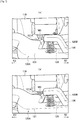
Fig. 1 , anelectrical connector 200 is fittable to apower receiving connector 300 provided with apower receiving terminal 301, and includes apower feeding terminal 211 that is connected to thepower receiving terminal 301 when theelectrical connector 200 is in a state of fitting to thepower receiving connector 300. - The
electrical connector 200 includes aconnector fitting portion 210 that is provided with thepower feeding terminal 211 therein and fits to thepower receiving connector 300, and aconnector case 220 that accommodates an electric wire W connected to thepower feeding terminal 211. - In the
connector case 220, the electric wire W connected to thepower feeding terminal 211 inside theconnector fitting portion 210 extends through ahandle portion 221 to the outside, and aslide portion 230 absorbing an expansion/contraction according to a slide operation of thepower feeding terminal 211, the electric wire W, or the like is provided between theconnector fitting portion 210 and thehandle portion 221. - When fitting the
electrical connector 200 to thepower receiving connector 300, a user holds thehandle portion 221 and presses theelectrical connector 200 against thepower receiving connector 300 to fit theconnector fitting portion 210 to thepower receiving connector 300. Thereafter, when the user holds thehandle portion 221 and pulls (turns) aturn lever 240, thepower feeding terminal 211 slides by aslide portion 230 together with the electric wire W and thus the fitting to thepower receiving terminal 301 of thepower receiving connector 300 is completed. At this time, thehandle portion 221 also moves in a fitting direction, and theslide portion 230 absorbs the sliding amount. - The
electrical connector 200 is provided with alever lock mechanism 250 that prevents theturn lever 240 from turning while thepower feeding terminal 211 and thepower receiving terminal 301 are being connected together. Accordingly, thepower feeding terminal 211 can be prevented from sliding in a fitting release direction while thepower feeding terminal 211 and thepower receiving terminal 301 are being connected together, and thus the connection between thepower feeding terminal 211 and thepower receiving terminal 301 can be prevented from being abruptly disconnected during the charge of a battery. -
US 5 639 256 A discloses a feeder connector comprising a feeding side connector on the power supply apparatus side and a receiving side connector on the car body side. The feeding side connector has a connector body, a protective case and a lock lever. The protective case consists of a main case made up of a cylinder portion, a half-cylinder portion and a trough portion, all formed integral, and a subcase. The connector body is formed integral with the cylinder portion of the main case through a flange formed along the periphery of the body. An opening is formed ranging from the cylinder portion of the main case to the subcase. In this opening, a lock lever for the receiving side connector is rotatably provided. - [PTL 1] Japanese Unexamined Patent Application Publication No.
10-275653 - However, in the above-described related
electrical connector 200, even when the connector fittingportion 210 is not in a state of completely fitting to thepower receiving connector 300, the battery may be in a state of being chargeable because theslide portion 230 disposed between theconnector fitting portion 210 and thehandle portion 221 may contract and thus thepower feeding terminal 211 may move to a fitting side together with the electric wire W. - That is, since the
electrical connector 200 cannot detect whether thepower receiving connector 300 and theconnector fitting portion 210 completely fit to each other, the battery may be charged while thepower receiving connector 300 and theconnector fitting portion 210 are in a state of half-fitting together. - An object of the present invention is to provide an electrical connector that can detect a fitting state between a power receiving connector and a connector fitting portion and thus can improve safety more securely.
- An electrical connector in accordance with some embodiments includes: a connector case including a connector fitting portion configured to fit to a power receiving connector and accommodating an electric wire; a power feeding terminal provided in the connector fitting portion and connected to the electric wire, the power feeding terminal being configured to be connected to a power receiving terminal of the power receiving connector in a fitting state where the power receiving connector and the connector fitting portion are fitted together; a lock mechanism configured to prevent the power receiving connector and the connector fitting portion from being separated from each other in the fitting state between the power receiving connector and the connector fitting portion; a fitting detecting mechanism configured to detect the fitting state between the power receiving connector and the connector fitting portion; and a lock release unit including an operating portion advanceable from and retractable to the connector case, and a latch portion configured to latch to a portion of the lock mechanism and a portion of the fitting detecting mechanism with the operating portion being retracted to the connector case. Upon release of the latching of the latch portion in the fitting state between the power receiving connector and the connector fitting portion, the operating portion of the lock release unit is configured to move in a direction where the operating portion advances from the connector case and become operatable to enable release of the fitting state between the power receiving connector and the connector fitting portion. The lock mechanism includes a first lock unit including a lock arm swingably provided in the connector case, and a lock claw provided at one end of the lock arm at a side of the power receiving connector and being protrudable and retractable from the connector fitting portion, and a second lock unit including an auxiliary arm connected to the lock arm, and an auxiliary latch piece provided at an end of the auxiliary arm and configured to latch to the latch portion of the lock release unit. The latching of the auxiliary latch piece to the latch portion of the lock release unit is released with the lock claw being retracted in the connector fitting portion by swing of the lock arm and the auxiliary arm. The fitting detecting mechanism includes a latch arm swingably provided in the connector case, a latch claw provided at one end of the latch arm at a side of the power receiving connector and being protrudable and retractable from the connector fitting portion, and a latch piece provided at the other end of the latch arm and being latchable to the latch portion of the lock release unit. The latch claw is provided at a nearer side than the lock claw in a fitting direction where the connector fitting portion is fitted to the power receiving connector. The latching of the latch piece to the latch portion of the lock release unit is released with the latch claw being retracted in the connector fitting portion by swing of the latch arm.
- According to the above configuration, the lock mechanism includes the first lock unit and the second lock unit. The latching of the auxiliary latch piece to the latch portion of the lock release unit is released with the lock claw being retracted in the connector fitting portion by swing of the lock arm and the auxiliary arm. The latch claw is provided on the nearer side than the lock claw in the fitting direction of the connector fitting portion to the power receiving connector. The latching of the latch piece to the latch portion of the lock release unit is released with the latch claw being retracted in the connector fitting portion by swing of the latch arm. Accordingly, the latch claw is retracted into the connector fitting portion by the abutting on the power receiving connector to be later than the lock claw. Therefore, the latching between the latch piece and the latch portion of the lock release unit by the swing of the latch arm is not released unless the latching between the auxiliary latch piece and the latch portion of the lock release unit by the swing of the lock arm is released.
- That is, when only the latching between the auxiliary latch piece and the latch portion of the lock release unit is released, the power receiving connector and the connector fitting portion are not in a state of completely fitting together and thus the operating portion of the lock release unit does not protrude from the connector case and is yet unoperatable. On the other hand, when the latching between the auxiliary latch piece and the latch portion of the lock release unit is released and also the latching between the latch piece and the latch portion of the lock release unit is released, the power receiving connector and the connector fitting portion are in a state of completely fitting together and thus the operating portion of the lock release unit protrudes from the connector case and becomes operatable. Accordingly, the fitting state between the power receiving connector and the connector fitting portion can be detected according to the positional state of the operating portion of the lock release unit. Therefore, the battery can be prevented from being charged in the half-fitting state, thus making it possible to improve stability more securely.
- The latch claw may be provided with the lock claw along the fitting direction.
- According to the above configuration, the latch claw is provided with the lock claw along the fitting direction. Accordingly, for example, when the power receiving connector is damaged, even when the lock claw does not abut the power receiving connector and only the latch claw abuts the power receiving connector and is retracted into the connector fitting portion, the latching between the lock piece and the latch portion of the lock release unit is not released. Therefore, when the power receiving connector and the connector fitting portion are not in a state of completely fitting together (that is, when the lock claw is not locked to the power receiving connector), the operating portion of the lock release unit does not protrude from the connector case and can be made unoperatable.
- The first lock unit may include a lock piece provided at the other end of the lock arm and being latchable to the latch portion of the lock release unit. The lock piece may be provided at a position facing the auxiliary latch piece.
- According to the above configuration, the lock piece is provided at a position facing the auxiliary latch piece. Accordingly, the lock piece and the auxiliary latch piece can be latched to the latch portion of the lock release unit, thus making it possible to provide double locking. Therefore, even when the latching between the auxiliary latch piece and the latch portion of the lock release unit is released, the operating portion of the lock release unit does not protrude from the connector case and is unoperatable until the latching between the lock piece and the latch portion of the lock release unit is released. Accordingly, the abrupt protrusion of the operating portion of the lock release unit from the connector case can be securely prevented.
- The first lock unit may include a lock arm shaft configured to pivotally support the lock arm to be swingable, and a lock arm bias member configured to bias the lock arm in a direction where the lock claw protrudes from the connector fitting portion. The fitting detecting mechanism may include a latch arm shaft configured to pivotally support the latch arm to be swingable, and a latch arm bias member configured to bias the latch arm in a direction where the latch claw protrudes from the connector fitting portion. The lock release unit may include a release bias member configured to bias the lock release unit in the direction where the operating portion advances from the connector case.
- According to the above-described configuration, it is possible to provide an electrical connector that can detect a fitting state between a power receiving connector and a connector fitting portion and thus can improve safety more securely.
-
- [
fig.1]Fig. 1 is a cross-sectional view illustrating a related electrical connector. - [
fig.2]Fig. 2 is a perspective view illustrating an electrical connector according to a present embodiment. - [
fig.3]Fig. 3 is a partially exploded perspective view illustrating the electrical connector according to the present embodiment. - [
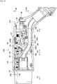
fig.4]Fig. 4 is a cross-sectional view illustrating the electrical connector according to the present embodiment. - [
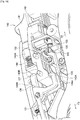
fig.5]Fig. 5 is a perspective view illustrating the inside of the electrical connector according to the present embodiment. - [
fig.6]Fig. 6 is an enlarged perspective view illustrating the neighborhood of a second lock unit (a lock arm is omitted herein) and a plan/side view of a lock claw and a latch claw according to the present embodiment. - [
fig.7]Fig. 7 is an enlarged perspective view illustrating a portion of a first lock unit and a portion of the second lock unit according to the present embodiment. - [
fig.8]Fig. 8 is an enlarged perspective view illustrating the neighborhood of a lock release unit according to the present embodiment. - [
fig.9]Fig. 9 is an enlarged perspective view illustrating the neighborhood of the first lock unit and a power feedability determining mechanism (the second lock unit is omitted herein) according to the present embodiment (No. 1). - [
fig.10]Fig. 10 is an enlarged perspective view illustrating the neighborhood of the first lock unit and the power feedability determining mechanism (the second lock unit is omitted herein) according to the present embodiment (No. 2). - [
fig.11]Fig. 11 is an enlarged perspective view illustrating the neighborhood of the lock release unit and the power feedability determining mechanism according to the present embodiment. - [
fig.12]Fig. 12 is an enlarged perspective view illustrating the neighborhood of the power feedability determining mechanism according to the present embodiment (No. 1). - [
fig.13]Fig. 13 is an enlarged perspective view illustrating the neighborhood of the power feedability determining mechanism according to the present embodiment (No. 2). - [
fig.14]Fig. 14 is an enlarged perspective view illustrating the neighborhood of a release switch hold portion according to the present embodiment. - [
fig.15]Fig. 15 is a plan view (top view) illustrating the inside of the electrical connector according to the present embodiment. - [
fig.16]Fig. 16 is a cross-sectional view illustrating an operation (separated state) of the electrical connector according to the present embodiment. - [
fig.17]Fig. 17 is a cross-sectional view illustrating an operation (fitting state) of the electrical connector according to the present embodiment (No. 1). - [
fig.18]Fig. 18 is a cross-sectional view illustrating an operation (fitting state) of the electrical connector according to the present embodiment (No. 2). - [
fig.19]Fig. 19 is an enlarged perspective view illustrating the neighborhood of a lock mechanism and the lock release unit according to the present embodiment (No. 1). - [
fig.20]Fig. 20 is a cross-sectional view illustrating an operation (fitted state) of the electrical connector according to the present embodiment. - [
fig.21]Fig. 21 is an enlarged perspective view illustrating the neighborhood of the lock mechanism and the lock release unit according to the present embodiment (No. 2). - [
fig.22]Fig. 22 is an enlarged perspective view illustrating an operation of a movable shaft of the power feedability determining mechanism according to the present embodiment (No. 1). - [
fig.23]Fig. 23 is an enlarged perspective view illustrating an operation of the movable shaft of the power feedability determining mechanism according to the present embodiment (No. 2). - [
fig.24]Fig. 24 is a cross-sectional view illustrating an operation (separating state) of the electrical connector according to the present embodiment (No. 1). - [
fig.25]Fig. 25 is a cross-sectional view illustrating an operation (separating state) of the electrical connector according to the present embodiment (No. 2). - [
fig.26]Fig. 26 is a cross-sectional view (partially enlarged cross-sectional view ofFig. 25 ) illustrating an operation of the electrical connector according to the present embodiment. - Hereinafter, an electrical connector according to embodiments of the present invention will be described with reference to the drawings. Specifically, (1) Configuration of Electrical Connector, (2) Operation of Electrical Connector, (3) Function and Effect, and (4) Other Embodiments will be described.
- Also, in the following description of the drawings, identical or similar reference numerals are given to identical or similar portions. However, it should be noted that the drawings are schematic and dimensional ratios and the like are different from actual ones.
- Accordingly, specific sizes and the like should be determined in consideration of the following description. In addition, there may be some differences in dimensional relations and ratios between the mutual drawings.
- First, a configuration of an
electrical connector 100 according to the present embodiment will be described with reference toFigs. 2 to 15. Figs. 2 to 15 are views for describing a configuration of theelectrical connector 100 according to the present embodiment. - As illustrated in
Figs. 2 to 4 , theelectrical connector 100 is fittable to apower receiving connector 10 provided with apower receiving terminal 11A (seeFig. 4 ) used for power feeding, and includes apower feeding terminal 111A that is connected to the power receiving terminal 11A when theelectrical connector 100 is in a state of fitting to thepower receiving connector 10. As illustrated inFig. 4 , thepower receiving connector 10 includes aconnector housing 11 that accommodates the power receiving terminal 11A and asignal terminal 11B for a control circuit such as signaling/ displaying, and ahood portion 12 that is integrated with theconnector housing 11 and has an inner periphery that fits to a front end of the electrical connector 100 (an outer periphery of a connector fitting portion 111). - As illustrated in
Figs. 3 and4 , theelectrical connector 100 includes aconnector case 110, alock mechanism 120, a fitting detectingmechanism 130, alock release unit 140, a powerfeedability determining mechanism 150, and a releaseswitch hold portion 160. - The
connector case 110 has a cylindrical shape. As illustrated inFig. 5 , theconnector case 110 includes the connectorfitting portion 111 that is provided with thepower feeding terminal 111A therein and fits to theconnector housing 11 of thepower receiving connector 10, and accommodates an electric wire W connected to thepower feeding terminal 111A. - A
terminal receiving chamber 112 accommodating thepower feeding terminal 111A is provided at the right and left sides of the connectorfitting portion 111, and a compositeterminal receiving chamber 113 accommodating asignal terminal 111B for a control circuit such as signaling/displaying is provided at top and bottom of the connector fitting portion 111 (seeFig. 2 ). The electric wire W is connected to thepower feeding terminal 111A and thesignal terminal 111B by pressure bonding or the like. - As illustrated in
Figs. 3 to 5 , alock chamber 114 accommodating thelock mechanism 120, the fitting detectingmechanism 130, and thelock release unit 140 is provided over the electric wire W in theconnector case 110. Ahandle portion 115 held by an operator is provided at a rear bottom of theconnector case 110, and the electric wire W extends through thehandle portion 115 to the outside. - The
lock mechanism 120 prevents the separation between thepower receiving connector 10 and theelectrical connector 100 when thepower receiving connector 10 and the connectorfitting portion 111 are in a state of fitting together (i.e. in a fitting state where thepower receiving connector 10 and the connectorfitting portion 111 are fitted together). As illustrated inFig. 5 , thelock mechanism 120 includes afirst lock unit 120A and asecond lock unit 120B. - As illustrated in
Figs. 5 and8 to 10 , thefirst lock unit 120A includes abiforked lock arm 121 that is swingably provided in theconnector case 110, a lock claw 122 (Figs. 2 ,4 and5 ) that is provided at one end of thelock arm 121 on apower receiving connector 10 side and is protrudable/retractable from an outer periphery of the connectorfitting portion 111, and alock piece 123 that is provided at the other end of thelock arm 121 and is latchable to alatch groove portion 143 of thelock release unit 140. - The
lock arm 121 is pivotally supported to be swingable by alock arm shaft 124, and thelock claw 122 is biased by acoil spring 125 as a lock arm bias member toward a top direction TD that is a protruding direction from the outer periphery of the connectorfitting portion 111. - The
lock arm 121 is bent at the side of thelock claw 122 from thelock arm shaft 124 in a width direction WD perpendicular to a fitting/separating direction FSD (seeFigs. 8 to 10 ). Thelock arm 121 is bent in a bottom direction BD at the position of thelock arm shaft 124, and thelock piece 123 extends from the bent front end in the fitting/ separating direction FSD (seeFigs. 5 and8 to 10 ). - The fitting/separating direction FSD includes a direction of fitting the
electrical connector 100 to the power receiving connector 10 (hereinafter referred to as a fitting direction FD) and a direction of separating theelectrical connector 100 from the power receiving connector 10 (hereinafter referred to as a separating direction SD). - The
lock arm 121 is provided with apressing portion 121A (seeFig. 14 ) that presses a micro switch MS that can detect the protrusion/retraction of thelock claw 122 from a cutout 116 (seeFigs. 2 ,4 and5 ) formed at the connectorfitting portion 111. As illustrated inFig. 7(a) , when thelock claw 122 protrudes from thecutout 116 of the connectorfitting portion 111, thepressing portion 121A does not press the micro switch MS. As illustrated inFig. 7(b) , when thelock claw 122 retracts into the connectorfitting portion 111, thepressing portion 121A presses the micro switch MS. - A
support groove 121B (seeFigs. 8 to 10 ) supporting thesecond lock unit 120B is formed at thelock arm 121, and thesecond lock unit 120B abuts an edge portion of thesupport groove 121B and thus swings together with thelock arm 121. - The
lock claw 122 is protrudable from/retractable to (advanceable from/retractable to) thecutout 116 of the connectorfitting portion 111 to the outside. Apower receiving connector 10 side of thelock claw 122 is provided with acam surface 122A inclining in the fitting/separating direction FSD, and a separating direction SD side of thelock claw 122 is provided with alock surface 122B perpendicular to the fitting/separating direction FSD (seeFig. 6(b) ). - The
lock piece 123 extends in the top direction TD, and is latchable to the latch groove portion 143 (firstlatch groove portion 143A) of thelock release unit 140. Thelock piece 123 is provided at a position facing alatch piece 133 of the fitting detectingmechanism 130, which will be described later. Anair gap 123A (seeFigs. 8 to 10 ) opening in the width direction WD perpendicular to the fitting/separating direction FSD is provided between thelock piece 123 and thelock arm 121. - While the
lock claw 122 is in a state of retracting into the connectorfitting portion 111, thelock arm 121 swings, so that thelock piece 123 latches to the latch groove portion 143 (firstlatch groove portion 143A) of thelock release unit 140. While thelock claw 122 is in a state of protruding from the connectorfitting portion 111, thelock arm 121 swings, so that the latching of thelock piece 123 to thelatch groove portion 143 of thelock release unit 140 is released. - As illustrated in
Figs. 5 and6 , thesecond lock unit 120B includes anauxiliary arm 126 that is connected to thelock arm 121, and anauxiliary latch piece 127 that is provided at an end of theauxiliary arm 126 on the near side in the fitting direction FD and is latchable to the latch groove portion 143 (secondlatch groove portion 143B) of thelock release unit 140. - The
auxiliary arm 126 is pivotally supported to be swingable by thelock arm shaft 124, and theauxiliary latch piece 127 is biased by acoil spring 129 in the bottom direction BD. Theauxiliary arm 126 is provided in thesupport groove 121 B formed at thelock arm 121, and swings together with thelock arm 121. - The
auxiliary latch piece 127 extends in the bottom direction BD, and is latchable to the latch groove portion 143 (secondlatch groove portion 143B) of thelock release unit 140. Theauxiliary latch piece 127 is provided at a position facing thelock piece 123. While thelock claw 122 is in a state of retracting into the connectorfitting portion 111, thelock arm 121 swings, so that the latching of theauxiliary latch piece 127 to the latch groove portion 143 (secondlatch groove portion 143B) of thelock release unit 140 is released. - A
power receiving connector 10 side of theauxiliary latch piece 127 is provided with alock surface 127B perpendicular to the fitting/separating direction FSD, and a separating direction SD side of theauxiliary latch piece 127 is provided with acam surface 127A inclining in the fitting/separating direction FSD (seeFigs. 6(a) and8 ). - The fitting detecting
mechanism 130 detects a fitting state between thepower receiving connector 10 and the connectorfitting portion 111. As illustrated inFigs. 5 and8 to 10 , the fitting detectingmechanism 130 includes alatch arm 131 that is swingably provided in theconnector case 110, a latch claw 132 (Figs. 2 ,4 and5 ) that is provided at one end of thelatch arm 131 on apower receiving connector 10 side and is protrudable/retractable from the connectorfitting portion 111, and alatch piece 133 that is provided at the other end of thelatch arm 131 and is latchable to the latch groove portion 143 (secondlatch groove portion 143B) of thelock release unit 140. - The
latch arm 131 is pivotably supported by alatch arm shaft 134, and thelatch claw 132 is biased by acoil spring 135 as a latch arm bias member toward the top direction TD that is the protruding direction from the outer periphery of the connectorfitting portion 111. - The
latch arm 131 includes aprotrusion 131A (seeFig. 6 ) as a latch state release portion that releases the latching between thelatch groove portion 143 and the release switch hold portion 160 (ahold latch piece 162 to be described later) when the later-described latch groove portion 143 (secondlatch groove portion 143B) of thelock release unit 140 and thelatch piece 133 latch together. Theprotrusion 131A protrudes in the bottom direction BD to abut the release switch hold portion 160 (ahold arm 161 to be described later). - The
latch claw 132 is protrudable/retractable (advanceable/retractable) to the outside from thecutout 116 formed at the connectorfitting portion 111. Apower receiving connector 10 side of thelatch claw 132 is provided with acam surface 132A inclining in the fitting/separating direction FSD, and a separating direction SD side of thelatch claw 132 is provided with aperpendicular surface 132B perpendicular to the fitting/separating direction FSD (seeFig. 6(c) ). Thelatch claw 132 is provided on the nearer side than thelock claw 122 in the fitting direction FD (that is, on the separating direction SD side of the lock claw 122), and is provided with thelock claw 122 along the fitting/separating direction FSD (or along the fitting direction FD). - A width W2 of the
latch claw 132 in the width direction WD is smaller than a width W1 of thelock claw 122 in the width direction WD (seeFigs. 6(b) and 6(c) ). That is, thelatch claw 132 is provided within a projection surface of thelock claw 122 when viewed from a front side of theelectrical connector 100. - The
latch piece 133 is provided on the nearer side than thelock claw 122 in the fitting direction of the connectorfitting portion 111 to thepower receiving connector 10. While thelatch claw 132 is in a state of retracting into the connectorfitting portion 111, thelatch arm 131 swings, so that the latching of thelatch piece 133 to the latch groove portion 143 (secondlatch groove portion 143B) of thelock release unit 140 is released. - The
lock release unit 140 is slidable in the fitting/separating direction FSD, and is biased by acoil spring 144 to a rear side of the fitting direction FD (that is, a separating direction SD side). As illustrated inFig. 5 , thelock release unit 140 includes arelease switch 141 as an operation portion advanceable from/retractable to theconnector case 110, and arelease body portion 142 integrated with therelease switch 141. Thelock release unit 140 releases the latch state between thepower receiving connector 10 and the connectorfitting portion 111 by the pressing operation of therelease switch 141. - The
release body portion 142 is provided with thelatch groove portion 143 as a latch portion that is latched to a portion (lockpiece 123 and auxiliary latch piece 127) of thelock mechanism 120 in theconnector case 110 and to a portion (latch piece 133) of the fitting detectingmechanism 130. Thelatch groove portion 143 includes the firstlatch groove portion 143A latching to thelock piece 123, and the secondlatch groove portion 143B latching to theauxiliary latch piece 127. The firstlatch groove portion 143A is provided at a bottom side of therelease body portion 142, and the secondlatch groove portion 143B is provided at a top side of therelease body portion 142 to face the firstlatch groove portion 143A. - A
spring support portion 142A biased by thecoil spring 144 as a release bias member is provided on the upper side of therelease body portion 142. By the biasing of thecoil spring 144 to therelease body portion 142, therelease switch 141 is movable in the direction of protruding from the connector case 110 (that is, the separating direction SD). That is, while thepower receiving connector 10 and the connectorfitting portion 111 are in a state of fitting together, when all the latching to thelatch groove portion 143 is released, therelease switch 141 moves in the separating direction SD and becomes operatable, so that thelock release unit 140 can be used to release the fitting state between thepower receiving connector 10 and the connectorfitting portion 111. - A regulation wall surface 145 (
Figs. 11 to 13 ) is provided under therelease body portion 142, and is movable in the fitting/separating direction FSD between amicro switch 151 and amovable shaft 153 of the powerfeedability determining mechanism 150. - The
regulation wall surface 145 moves in the fitting/separating direction FSD together with therelease switch 141 and therelease body portion 142. Specifically, when all the latch pieces (lockpiece 123,auxiliary latch piece 127, and latch piece 133) latch to thelatch groove portion 143, therelease switch 141 is in a state of being pressed and theregulation wall surface 145 is located between themicro switch 151 and themovable shaft 153 as illustrated inFig. 12 . On the other hand, when all the latching to thelatch groove portion 143 is released, therelease switch 141 protrudes from theconnector case 110, so that theregulation wall surface 145 retracts from a portion between themicro switch 151 and themovable shaft 153 as illustrated inFig. 13 . - The power feedability determining
mechanism 150 determines the power feedability between thepower receiving connector 10 and the connectorfitting portion 111 by enabling power feeding when thepower receiving connector 10 and the connectorfitting portion 111 are in a state of fitting together (in a complete fitting state), and by disabling power feeding when thepower receiving connector 10 and the connectorfitting portion 111 are in a state of half-fitting together (in an incomplete fitting state). - As illustrated in
Figs. 8 to 10 ,11 , and12 , the powerfeedability determining mechanism 150 includes themicro switch 151 and asolenoid 152 that is provided at a position spaced apart from themicro switch 151 in the width direction WD. - The
micro switch 151 does not flow a current from theelectrical connector 100 to thepower receiving connector 10 when themicro switch 151 is not in a state of being abutted by a portion (movable shaft 153 to be described below) of thesolenoid 152. - The
solenoid 152 includes amovable shaft 153 that moves in the width direction WD when thepower receiving connector 10 and the connectorfitting portion 111 change from a half-fitting state to a fitting state, and a regulation arm 154 (seeFigs. 9 and10 ) that moves according to the movement of themovable shaft 153. - The
movable shaft 153 moves according to information (instruction) from a power supply unit (not illustrated) connected to an end portion of the electric wire W extending from thehandle portion 115 to the outside. When the above-describedregulation wall surface 145 of thelock release unit 140 is located between themicro switch 151 and themovable shaft 153, themovable shaft 153 does not abut the micro switch 151 (seeFig. 12 ). - The
regulation arm 154 is insertable/extractable into/from theair gap 123A formed at thelock arm 121. Theregulation arm 154 is inserted into theair gap 123A to regulate the swing of thelock arm 121. As illustrated inFigs. 8 to 10 , theregulation arm 154 includes aconnection portion 154A connected to themovable shaft 153, anarm portion 154B provided in the fitting/separating direction FSD, and afront end portion 154C insertable into theair gap 123A. For example, as illustrated inFig. 9 , thefront end portion 154C is located outside theair gap 123A when themovable shaft 153 is in a state of being spaced apart from themicro switch 151. On the other hand, as illustrated inFig. 10 , when thefront end portion 154C moves in the width direction WD together with themovable shaft 153 and themovable shaft 153 is in a state of abutting themicro switch 151, thefront end portion 154C is located inside theair gap 123A. - The release
switch hold portion 160 holds therelease switch 141 of thelock release unit 140 when therelease switch 141 is in a state of being pressed. As illustrated inFigs. 14 and15 , the releaseswitch hold portion 160 includes ahold arm 161 that is swingably provided in theconnector case 110, and ahold latch piece 162 that is provided at a near side end portion of thehold arm 161 in the fitting direction FD and is latched to the secondlatch groove portion 143B of thelock release unit 140 at a position where therelease switch 141 is pressed. - The
hold arm 161 is pivotably supported by ahold arm shaft 163, and a rear side in the fitting direction FD (that is, the separating direction SD side) is biased by acoil spring 164 as a hold arm bias member toward the bottom direction BD. - Next, an operation of the
electrical connector 100 according to the present embodiment will be described with reference to the drawings.Figs. 16 to 26 are views for describing an operation of theelectrical connector 100 according to the present embodiment. - The
electrical connector 100 charges a battery (not illustrated) mounted on a vehicle such as an electric vehicle (EV) or a hybrid electric vehicle (HEV) according to information (instruction) from a power supply unit (not illustrated) connected to an end portion of the electric wire W extending from thehandle portion 115 to the outside, when being in a state of fitting to thepower receiving connector 10. - As illustrated in
Fig. 16 , when thepower receiving connector 10 and theelectrical connector 100 are in a state of separating from each other, thelock claw 122 and thelatch claw 132 protrude from thecutout 116 of the connectorfitting portion 111. At this time, thelatch piece 133 is latched to the secondlatch groove portion 143B of thelock release unit 140. Since theauxiliary latch piece 127 of thesecond lock unit 120B is provided on the separating direction SD side from thelatch piece 133, theauxiliary latch piece 127 is in a state of being immediately latchable to the secondlatch groove portion 143B when the latching between thelatch piece 133 and the secondlatch groove portion 143B is released while theauxiliary latch piece 127 is not in a state of being completely latched to the secondlatch groove portion 143B. In this separating state, therelease switch 141 is in a state of being unoperatable. - Subsequently, as illustrated in
Fig. 17 , when thepower receiving connector 10 and theelectrical connector 100 are gradually fitted together, thehood portion 12 of thepower receiving connector 10 retreats (presses) thelock claw 122 into the connectorfitting portion 111. Then, thelock arm 121 swings, and thus theauxiliary latch piece 127 deviates from the secondlatch groove portion 143B. At this time, thelatch piece 123 is inserted into the firstlatch groove portion 143A of thelock release unit 140. - Subsequently, as illustrated in
Fig. 18 , when thepower receiving connector 10 and theelectrical connector 100 are further fitted together, thehood portion 12 of thepower receiving connector 10 presses thelatch claw 132 into the connectorfitting portion 111. Then, thelatch arm 131 swings, and thus thelatch piece 133 removes from the secondlatch groove portion 143B. Then, as illustrated inFig. 19 , thelock piece 123 is latched to the firstlatch groove portion 143A of thelock release unit 140, and therelease switch 141 is yet in a state of being unoperatable. - Subsequently, as illustrated in
Fig. 20 , when thepower receiving connector 10 and theelectrical connector 100 are completely fitted together, thelock claw 122 protrudes from thecutout 116 of the connectorfitting portion 111 in thehood portion 12 of thepower receiving connector 10 to be latched to thepower receiving connector 10, and thelock piece 123 removes from the firstlatch groove portion 143A of thelock release unit 140. - As illustrated in
Figs. 20 and21 , therelease switch 141 moves toward the separating direction SD because all the latching to thelatch groove portion 143 is released. Accordingly, theregulation wall surface 145 of thelock release unit 140 located between themicro switch 151 and themovable shaft 153 moves to the separating direction SD side. Then, as illustrated inFig. 22 , themovable shaft 153 of the powerfeedability determining mechanism 150 protrudes along the width direction WD and presses themicro switch 151, thereby becoming a chargeable state. - As illustrated in
Fig. 23 , in a charge mode, even when therelease switch 141 is about to be moved in the fitting direction FD, theregulation wall surface 145 bumps against themovable shaft 153 abutting themicro switch 151. This may make it impossible to operate therelease switch 141. - In addition, the
regulation arm 154 is inserted into theair gap 123A of the lock arm 121 (seeFig. 10 ). Therefore, even when therelease switch 141 is about to be moved in the fitting direction FD, the swing of thelock arm 121 can be prevented, so that the removal of thelock claw 122 from theconnector housing 11 can be prevented. - Accordingly, the fitting of the
power receiving connector 10 and the connectorfitting portion 111 can be prevented from being accidentally released when charging the battery (not illustrated) mounted on the vehicle. - When the charging of the battery (not illustrated) mounted to the vehicle is completed, the
movable shaft 153 of thesolenoid 152 returns to the original state, so that the abutting between themicro switch 151 and themovable shaft 153 is released (seeFig. 13 ). Then, a gap occurs between themicro switch 151 and themovable shaft 153, and theregulation arm 154 retracts from theair gap 123A of the lock arm 121 (seeFig. 9 ). Accordingly, thelock release unit 140 is movable along the fitting direction FD. - Subsequently, as illustrated in
Fig. 24 , when therelease switch 141 is pressed against the fitting direction FD side, therelease body portion 142 of thelock release unit 140 abuts aninclined surface 121C of thelock arm 121 and slides on theinclined surface 121C. Then, since thelock arm 121 swings, thelock piece 123 is latched to the firstlatch groove portion 143A of thelock release unit 140 and thehold latch piece 162 of the releaseswitch hold portion 160 is latched to the secondlatch groove portion 143B of thelock release unit 140. At this time, since thelock claw 122 is retracted into the connectorfitting portion 111, thepower receiving connector 10 and theelectrical connector 100 can be separated from each other. - Subsequently, as illustrated in
Figs. 25 and26 , when thepower receiving connector 10 and theelectrical connector 100 are gradually separated from each other, thelatch arm 131 swings and thelatch claw 132 protrudes from thecutout 116 of the connectorfitting portion 111, so that thelatch piece 133 is latched to the secondlatch groove portion 143B of thelock release unit 140. At this time, theprotrusion 131A of thelatch arm 131 swings thehold arm 161 such that the fitting direction FD side is located in the bottom direction BD to be lower than thehold arm shaft 163 of thehold arm 161. Accordingly, thehold latch piece 162 of the releaseswitch hold portion 160 removes from the secondlatch groove portion 143B of thelock release unit 140. - Then, when the
power receiving connector 10 and theelectrical connector 100 are completely separated from each other, thelock claw 122 protrudes from thecutout 116 of the connector fitting portion 111 (seeFig. 16 ). Simultaneously, thelock piece 123 removes from the firstlatch groove portion 143A of thelock release unit 140, and theauxiliary latch piece 127 is in a state of being latchable to the secondlatch groove portion 143B of thelock release unit 140. - In the above-described embodiment, while the
lock claw 122 is in a state of retracting into the connectorfitting portion 111, thelock arm 121 and theauxiliary arm 126 swing, so that the latching of theauxiliary latch piece 127 to the secondlatch groove portion 143B is released. In addition, thelatch claw 132 is provided on the nearer side than thelock claw 122 in the fitting direction FD of the connectorfitting portion 111 to thepower receiving connector 10. While thelatch claw 132 is in a state of retracting into the connectorfitting portion 111, thelatch arm 131 swings, so that the latching between thelatch piece 133 and the secondlatch groove portion 143B is released. Accordingly, thelatch claw 132 is retracted into the connectorfitting portion 111 by the abutting on thehood portion 12 of thepower receiving connector 10 to be later than thelock claw 122. Therefore, the latching between thelatch piece 133 and the secondlatch groove portion 143B by the swing of thelatch claw 132 is not released unless the latching between theauxiliary latch piece 127 and the secondlatch groove portion 143B by the swing of theauxiliary arm 126 is released. - That is, when only the latching between the
auxiliary latch piece 127 and the secondlatch groove portion 143B by the swing of theauxiliary arm 126 is released, thepower receiving connector 10 and the connectorfitting portion 111 are not in a state of completely fitting together, and thus therelease switch 141 does not protrude from theconnector case 110 and is yet unoperatable. On the other hand, when the latching between thelock piece 123 or theauxiliary latch piece 127 and thelatch groove portion 143 is released and also the latching between thelatch piece 133 and the secondlatch groove portion 143B is released, thepower receiving connector 10 and the connectorfitting portion 111 are in a state of completely fitting together, and thus therelease switch 141 protrudes from theconnector case 110 and is operatable. Accordingly, the fitting state between thepower receiving connector 10 and the connectorfitting portion 111 can be detected according to the positional state of therelease switch 141. Therefore, the battery can be prevented from being charged in the half-fitting state, thus making it possible to improve stability more securely. - In the present embodiment, the
latch claw 132 is provided with thelock claw 122 along the fitting direction FD. Accordingly, for example, when theconnector housing 11 or thehood portion 12 of thepower receiving connector 10 is damaged, even when thelock claw 122 does not abut thehood portion 12 of thepower receiving connector 10 and only thelatch claw 132 abuts thehood portion 12 and is retracted into the connectorfitting portion 111, the latching between thelock piece 123 or theauxiliary latch piece 127 and thelatch groove portion 143 is not released. Therefore, when thepower receiving connector 10 and the connectorfitting portion 111 are not in a state of completely fitting together (that is, when thelock claw 122 is not locked to the connector housing 11), therelease switch 141 does not protrude from theconnector case 110 and can be made unoperatable. - In the present embodiment, the
lock piece 123 is provided at a position facing theauxiliary latch piece 127. Accordingly, thelock piece 123 and theauxiliary latch piece 127 can be latched to the latch groove portion 143 (firstlatch groove portion 143A and secondlatch groove portion 143B) of thelock release unit 140, thus making it possible to provide double locking. Therefore, even when the latching between theauxiliary latch piece 127 and the secondlatch groove portion 143B is released, therelease switch 141 does not protrude from theconnector case 110 and is unoperatable until the latching between thelock piece 123 and the firstlatch groove portion 143A is released. Accordingly, the abrupt protrusion of therelease switch 141 from theconnector case 110 can be securely prevented. - In the present embodiment, while the
lock claw 122 is in a state of retracting into the connectorfitting portion 111, thelock arm 121 swings and thelock piece 123 is latched to the firstlatch groove portion 143A. While thelock claw 122 is in a state of protruding from the connectorfitting portion 111, thelock arm 121 swings and the latching of thelock piece 123 to the firstlatch groove portion 143A is released. That is, the latching between thelock piece 123 and the firstlatch groove portion 143A by the swing of thelock arm 121 is not released unless thelock claw 122 protrudes from the connector fitting portion 111 (that is, unless thelock claw 122 is locked to the power receiving connector 10). Therefore, until thelock claw 122 is locked to thepower receiving connector 10, therelease switch 141 does not protrude from theconnector case 110 and can be made unoperatable, thus making it possible to improve safety more securely. - In the present embodiment, the width W2 of the
latch claw 132 is smaller than the width W1 of thelock claw 122. Accordingly, it is possible to prevent the case where thelock claw 122 is not retracted into the connectorfitting portion 111 and only thelatch claw 132 is abruptly retracted into the connectorfitting portion 111. - In the present embodiment, the
regulation wall surface 145 is provided under therelease body portion 142, and is movable in the fitting/separating direction FSD between themicro switch 151 and themovable shaft 153 of the powerfeedability determining mechanism 150. Accordingly, when therelease switch 141 protrudes from theconnector case 110 and is operatable, theregulation wall surface 145 retracts from the portion between themicro switch 151 and themovable shaft 153. Therefore, unless thepower receiving connector 10 and the connectorfitting portion 111 are not completely fitted together, themicro switch 151 is not turned on, and the battery can be prevented from being charged. - Also, in a charge mode, even when the
release switch 141 is about to be moved in the fitting direction FD, theregulation wall surface 145 bumps against themovable shaft 153 abutting themicro switch 151. Therefore, in the charge mode, therelease switch 141 can be prevented from moving in the fitting direction FD, so that the operation of therelease switch 141 can be prevented. That is, in the charge mode, thelock claw 122 can be prevented from being removed and released from thepower receiving connector 10, so that thepower receiving connector 10 and the connectorfitting portion 111 can be prevented from be separated from each other due to a fitting error thereof. - In the present embodiment, the
regulation arm 154 is insertable/extractable into/from theair gap 123A of thelock arm 121 according to the movement of themovable shaft 153, and is inserted into theair gap 123A to regulate the swing of thelock arm 121. Accordingly, thelock arm 121 does not swing when thelock claw 122 is in a state of protruding from the connectorfitting portion 111. Therefore, the fitting of thepower receiving connector 10 and the connectorfitting portion 111 can be prevented from be accidentally released during charging. - In the present embodiment, the
electrical connector 100 further includes the releaseswitch hold portion 160 that holds the position of thelock release unit 140 while therelease switch 141 is in a state of being pressed. Accordingly, even when therelease switch 141 is not continuously pressed in the fitting direction FD, therelease switch 141 does not protrude from theconnector case 110 and can be held in an unoperatable state. Accordingly, the operability is improved because an operator need not perform the operation while pressing therelease switch 141. - In addition, the
latch arm 131 includes theprotrusion 131A that releases the latching between thehold latch piece 162 and the secondlatch groove portion 143B when thelatch piece 133 and the secondlatch groove portion 143B are latched together. That is, while therelease switch 141 does not protrude from theconnector case 110, the latching between thehold latch piece 162 and the secondlatch groove portion 143B is released and thelatch piece 133 and the secondlatch groove portion 143B are latched together. Therefore, therelease switch 141 can be prevented from protruding from theconnector case 110 accidentally when the connectorfitting portion 111 is separated from thepower receiving connector 10. - Although the present invention has been described based on the above embodiments, it should not be understood that the statements and the drawings constituting a part of this disclosure limit the present invention. From this disclosure, various alternative embodiments, examples, and operation techniques will become apparent to those skilled in the art.
- For example, the embodiments of the present invention may be changed as follows. Specifically, although the
electrical connector 100 has been described as a connector charging a battery (not illustrated) mounted on a vehicle such as an electric vehicle (EV) or a hybrid electric vehicle (HEV), the present invention is not limited thereto. Theelectrical connector 100 may be used to charge other batteries. - Also, although the respective arms have been described as being biased by coil springs as bias members, the present invention is not limited thereto. The respective arms may be biased by other springs, cylinders, or the like.
- Also, the respective configurations of the
electrical connector 100 are not limited to the description in the present embodiment, and may be any other configurations that can be implemented. For example, it is only required that theelectrical connector 100 includes at least theconnector case 110, thelock mechanism 120, the fitting detectingmechanism 130, and thelock release unit 140. Theelectrical connector 100 may not include the powerfeedability determining mechanism 150 and the releaseswitch hold portion 160. - As described above, the present invention naturally includes various embodiments that are not described herein. Accordingly, the technical scope of the present invention should be only determined according to the subject matter recited in the scope of claims regarded as appropriate based on the above description.
Claims (4)
- An electrical connector (100) comprising:a connector case (110) including a connector fitting portion (111) configured to fit to a power receiving connector (10) and accommodating an electric wire (W);a power feeding terminal (111A) provided in the connector fitting portion (111) and connected to the electric wire (W), the power feeding terminal (111A) being configured to be connected to a power receiving terminal (11A) of the power receiving connector (10) in a fitting state where the power receiving connector (10) and the connector fitting portion (111) are fitted together;a lock mechanism (120) configured to prevent the power receiving connector (10) and the connector fitting portion (111) from being separated from each other in the fitting state between the power receiving connector (10) and the connector fitting portion (111);a fitting detecting mechanism (130) configured to detect the fitting state between the power receiving connector (10) and the connector fitting portion (111); anda lock release unit (140) including an operating portion (141) advanceable from and retractable to the connector case (110), and a latch portion (143, 143B) configured to latch to a portion of the lock mechanism (120) and a portion of the fitting detecting mechanism (130) with the operating portion (141) being retracted to the connector case (110),wherein, upon release of the latching of the latch portion (143, 143B) in the fitting state between the power receiving connector (10) and the connector fitting portion (111), the operating portion (141) of the lock release unit (140) is configured to move in a direction where the operating portion (141) advances from the connector case (110) and become operatable to enable release of the fitting state between the power receiving connector (10) and the connector fitting portion (111),wherein the lock mechanism (120) comprises a first lock unit (120A) includinga lock arm (121) swingably provided in the connector case (110), anda lock claw (122) provided at one end of the lock arm (121) at a side of the power receiving connector (10) and being protrudable and retractable from the connector fitting portion(111), andcharacterized in that, the lock mechanism further comprises:a second lock unit (120B) includingan auxiliary arm (126) connected to the lock arm (121), andan auxiliary latch piece (127) provided at an end of the auxiliary arm (126) and configured to latch to the latch portion (143, 143B) of the lock release unit (140),wherein the latching of the auxiliary latch piece (127) to the latch portion (143, 143B) of the lock release unit (140) is released with the lock claw (122) being retracted in the connector fitting portion (111) by swing of the lock arm (121) and the auxiliary arm (126),wherein the fitting detecting mechanism (130) includesa latch arm (131) swingably provided in the connector case (110),a latch claw (132) provided at one end of the latch arm (131) at a side of the power receiving connector (10) and being protrudable and retractable from the connector fitting portion (111), anda latch piece (133) provided at the other end of the latch arm (131) and being latchable to the latch portion (143, 143B) of the lock release unit (143),wherein the latch claw (132) is provided at a nearer side than the lock claw (122) in a fitting direction where the connector fitting portion (111) is fitted to the power receiving connector (10), andwherein the latching of the latch piece (133) to the latch portion (143, 143B) of the lock release unit (140) is released with the latch claw (132) being retracted in the connector fitting portion (111) by swing of the latch arm (131).
- The electrical connector (100) according to claim 1, wherein the latch claw (132) is provided with the lock claw (122) along the fitting direction.
- The electrical connector (100) according to claim 1 or 2, whereinthe first lock unit (120A) includes a lock piece (123) provided at the other end of the lock arm (121) and being latchable to the latch portion (143, 143B) of the lock release unit (140), andthe lock piece (123) is provided at a position facing the auxiliary latch piece (127).
- The electrical connector (100) according to any one of claims 1 to 3, whereinthe first lock unit (120A) includesa lock arm shaft (124) configured to pivotally support the lock arm (121) to be swingable, anda lock arm bias member (125) configured to bias the lock arm (121) in a direction where the lock claw (122) protrudes from the connector fitting portion (111),the fitting detecting mechanism (130) includesa latch arm shaft (134) configured to pivotally support the latch arm (131) to be swingable, anda latch arm bias member (135) configured to bias the latch arm (131) in a direction where the latch claw (132) protrudes from the connector fitting portion (111), andthe lock release unit (140) includes a release bias member (144) configured to bias the lock release unit (140) in the direction where the operating portion (141) advances from the connector case (110).
Applications Claiming Priority (2)
| Application Number | Priority Date | Filing Date | Title |
|---|---|---|---|
| JP2012007302A JP5798935B2 (en) | 2012-01-17 | 2012-01-17 | Electrical connector |
| PCT/JP2012/008120 WO2013108340A1 (en) | 2012-01-17 | 2012-12-19 | Electrical connector |
Publications (2)
| Publication Number | Publication Date |
|---|---|
| EP2805384A1 EP2805384A1 (en) | 2014-11-26 |
| EP2805384B1 true EP2805384B1 (en) | 2018-01-24 |
Family
ID=47666439
Family Applications (1)
| Application Number | Title | Priority Date | Filing Date |
|---|---|---|---|
| EP12821320.4A Active EP2805384B1 (en) | 2012-01-17 | 2012-12-19 | Electrical connector |
Country Status (5)
| Country | Link |
|---|---|
| US (1) | US9106015B2 (en) |
| EP (1) | EP2805384B1 (en) |
| JP (1) | JP5798935B2 (en) |
| CN (1) | CN104025388B (en) |
| WO (1) | WO2013108340A1 (en) |
Families Citing this family (13)
| Publication number | Priority date | Publication date | Assignee | Title |
|---|---|---|---|---|
| JP5798935B2 (en) * | 2012-01-17 | 2015-10-21 | 矢崎総業株式会社 | Electrical connector |
| JP5939927B2 (en) * | 2012-08-06 | 2016-06-22 | 矢崎総業株式会社 | Charging connector |
| JP5981294B2 (en) * | 2012-10-12 | 2016-08-31 | 矢崎総業株式会社 | Charging inlet device |
| EP2722724B1 (en) * | 2012-10-16 | 2017-10-11 | ABB Schweiz AG | Maximum power point tracking |
| DE102013101492B4 (en) * | 2013-02-14 | 2022-08-04 | Phoenix Contact E-Mobility Gmbh | Locking device for a plug connection |
| WO2014157196A1 (en) * | 2013-03-28 | 2014-10-02 | 矢崎総業株式会社 | Charging connector |
| JP6148964B2 (en) * | 2013-10-17 | 2017-06-14 | 日本航空電子工業株式会社 | connector |
| JP5690914B1 (en) * | 2013-12-16 | 2015-03-25 | 株式会社フジクラ | Power supply connector |
| WO2016077690A1 (en) | 2014-11-14 | 2016-05-19 | Henderson Ricky Jay | Power docking port system |
| JP6452563B2 (en) * | 2015-07-14 | 2019-01-16 | 日本航空電子工業株式会社 | Electrical connector and return jig |
| DE102016105371A1 (en) * | 2016-03-22 | 2017-09-28 | Phoenix Contact E-Mobility Gmbh | Connector part for plug-in connection with a mating connector part |
| EP3646074B1 (en) * | 2017-06-28 | 2021-06-02 | Corning Research & Development Corporation | Fiber optic connectors having a keying structure |
| DE102018131610A1 (en) * | 2018-12-10 | 2020-06-10 | Phoenix Contact E-Mobility Gmbh | Charging plug with a detent connection detection |
Family Cites Families (87)
| Publication number | Priority date | Publication date | Assignee | Title |
|---|---|---|---|---|
| JP2978348B2 (en) * | 1992-12-18 | 1999-11-15 | 矢崎総業株式会社 | Power supply connector |
| JP3042816B2 (en) * | 1992-12-18 | 2000-05-22 | 矢崎総業株式会社 | Power supply connector |
| US5429524A (en) * | 1993-04-16 | 1995-07-04 | Sumitomo Wiring Systems, Ltd. | Coupling device of charging connector assembly for electric car |
| US5433623A (en) * | 1993-04-19 | 1995-07-18 | Sumitomo Wiring Systems, Ltd. | Coupling device of charging connector assembly for electric car |
| JP3316049B2 (en) * | 1993-06-14 | 2002-08-19 | 住友電装株式会社 | Electric vehicle charging device |
| JP2929900B2 (en) * | 1993-06-22 | 1999-08-03 | 住友電装株式会社 | Connector connection terminal |
| US5458496A (en) * | 1993-07-12 | 1995-10-17 | Sumitomo Wiring Systems, Ltd. | Charge coupling for electric vehicle |
| JP2752032B2 (en) * | 1993-09-20 | 1998-05-18 | 矢崎総業株式会社 | Power supply connector |
| JP2879810B2 (en) * | 1993-12-28 | 1999-04-05 | 矢崎総業株式会社 | connector |
| JP3433432B2 (en) * | 1993-12-28 | 2003-08-04 | 矢崎総業株式会社 | Power supply connector |
| JP2921640B2 (en) * | 1994-03-17 | 1999-07-19 | 矢崎総業株式会社 | Power supply connector |
| JP3463820B2 (en) * | 1994-04-01 | 2003-11-05 | 矢崎総業株式会社 | Power supply connector |
| JP2904024B2 (en) * | 1994-08-08 | 1999-06-14 | 住友電装株式会社 | Electric vehicle charging connector |
| DE19544942C2 (en) * | 1994-12-01 | 2001-12-06 | Yazaki Corp | Connecting device with a voltage supply connector and a voltage receiving connector and method for connecting / disconnecting a voltage supply device |
| JP3135040B2 (en) * | 1995-11-30 | 2001-02-13 | 矢崎総業株式会社 | Electric vehicle charging connector |
| JP3292278B2 (en) * | 1995-12-06 | 2002-06-17 | 矢崎総業株式会社 | Electric vehicle charging connector |
| JPH09161882A (en) * | 1995-12-06 | 1997-06-20 | Yazaki Corp | Charging connector for electric vehicle |
| JP3262203B2 (en) * | 1996-02-16 | 2002-03-04 | 矢崎総業株式会社 | Low insertion / extraction force connector |
| JPH10112349A (en) * | 1996-10-04 | 1998-04-28 | Yazaki Corp | Charging connector for electric vehicle |
| US6371768B1 (en) * | 1998-03-31 | 2002-04-16 | Daimlerchrysler Corporation | Universal charge port connector for electric vehicles |
| JP3076299B2 (en) | 1998-04-09 | 2000-08-14 | 矢崎総業株式会社 | connector |
| US6225153B1 (en) * | 1999-03-24 | 2001-05-01 | Daimlerchrysler Corporation | Universal charge port connector for electric vehicles |
| JP3731797B2 (en) * | 1999-11-08 | 2006-01-05 | 矢崎総業株式会社 | Power supply connector |
| CN2833938Y (en) * | 2005-10-26 | 2006-11-01 | 中国第一汽车集团公司 | Connector for ABS sensor detection of automobile |
| US7404720B1 (en) * | 2007-03-29 | 2008-07-29 | Tesla Motors, Inc. | Electro mechanical connector for use in electrical applications |
| JP5123144B2 (en) * | 2008-11-21 | 2013-01-16 | 矢崎総業株式会社 | Charging connector |
| JP4898855B2 (en) * | 2009-02-04 | 2012-03-21 | 矢崎総業株式会社 | connector |
| JP5312214B2 (en) * | 2009-06-11 | 2013-10-09 | 矢崎総業株式会社 | Lever-type electrical connector with misoperation prevention |
| US7963793B2 (en) * | 2009-09-24 | 2011-06-21 | Lear Corporation | Hybrid/electric vehicle charge handle latch mechanism |
| JP4872032B2 (en) * | 2009-12-28 | 2012-02-08 | 株式会社フジクラ | Power supply connector |
| US8016607B2 (en) * | 2010-01-08 | 2011-09-13 | Lear Corporation | Connector assembly for electric vehicle charging |
| JP5447962B2 (en) * | 2010-02-19 | 2014-03-19 | 住友電装株式会社 | Charging connector |
| JP5392151B2 (en) * | 2010-03-09 | 2014-01-22 | 住友電装株式会社 | Charging connector |
| JP5482295B2 (en) * | 2010-03-01 | 2014-05-07 | 住友電装株式会社 | Charging connector |
| JP5504987B2 (en) * | 2010-03-11 | 2014-05-28 | 住友電装株式会社 | Charging connector |
| JP2011198566A (en) * | 2010-03-18 | 2011-10-06 | Sumitomo Wiring Syst Ltd | Charging connector |
| JP5096518B2 (en) * | 2010-05-12 | 2012-12-12 | 株式会社東海理化電機製作所 | Power supply plug lock device |
| US8075329B1 (en) * | 2010-06-08 | 2011-12-13 | Ford Global Technologies, Llc | Method and system for preventing disengagement between an electrical plug and a charge port on an electric vehicle |
| DE102010017458B4 (en) * | 2010-06-18 | 2012-02-16 | Phoenix Contact Gmbh & Co. Kg | electric plug |
| JP5471890B2 (en) * | 2010-06-28 | 2014-04-16 | 住友電装株式会社 | Charging connector |
| US7878866B1 (en) * | 2010-07-02 | 2011-02-01 | Lear Corporation | Connector assembly for vehicle charging |
| JP5197699B2 (en) * | 2010-09-09 | 2013-05-15 | 住友電装株式会社 | Charging connector |
| JP5890091B2 (en) * | 2010-10-29 | 2016-03-22 | 日本航空電子工業株式会社 | Electric connector, electric connector unit, and charger for electric vehicle |
| JP5739644B2 (en) * | 2010-11-02 | 2015-06-24 | 矢崎総業株式会社 | Power supply connector |
| US20120126747A1 (en) * | 2010-11-19 | 2012-05-24 | Delphi Technologies, Inc. | Battery charger having non-contact electrical switch |
| US20120129378A1 (en) * | 2010-11-19 | 2012-05-24 | Delphi Technologies, Inc. | Battery charger having handle that includes light source that emits light through aperture in handle connector |
| US8568155B2 (en) * | 2010-12-30 | 2013-10-29 | General Cable Technologies Corporation | Laminous multi-polymeric high amperage over-molded connector assembly for plug-in hybrid electric vehicle charging |
| JP5080662B2 (en) * | 2011-01-27 | 2012-11-21 | 日本航空電子工業株式会社 | connector |
| JP5775332B2 (en) * | 2011-03-04 | 2015-09-09 | 矢崎総業株式会社 | connector |
| JP5609725B2 (en) * | 2011-03-17 | 2014-10-22 | 住友電装株式会社 | Wire holding member |
| JP5645077B2 (en) * | 2011-03-17 | 2014-12-24 | 住友電装株式会社 | Charging connector |
| JP2012212647A (en) * | 2011-03-18 | 2012-11-01 | Tokai Rika Co Ltd | Power supply plug lock device |
| JP5650572B2 (en) * | 2011-03-29 | 2015-01-07 | 株式会社東海理化電機製作所 | Power supply plug lock device |
| DE102011002024A1 (en) * | 2011-04-13 | 2012-10-18 | Tyco Electronics Amp Gmbh | Charging plug with contactless switching device |
| JP5762129B2 (en) * | 2011-05-20 | 2015-08-12 | 矢崎総業株式会社 | Half-mating prevention connector |
| JP5715879B2 (en) * | 2011-05-20 | 2015-05-13 | 矢崎総業株式会社 | Arc discharge prevention connector |
| JP5721536B2 (en) * | 2011-05-20 | 2015-05-20 | 矢崎総業株式会社 | Half-mating prevention connector |
| US8834202B2 (en) * | 2011-06-13 | 2014-09-16 | Lear Corporation | Connector assembly for vehicle charging |
| JP2013053470A (en) * | 2011-09-05 | 2013-03-21 | Tokai Rika Co Ltd | Lock device |
| JP2013053471A (en) * | 2011-09-05 | 2013-03-21 | Tokai Rika Co Ltd | Power feeding plug lock device |
| JP5970767B2 (en) * | 2011-09-27 | 2016-08-17 | 日産自動車株式会社 | Charger |
| JP5648751B2 (en) * | 2011-10-11 | 2015-01-07 | 日産自動車株式会社 | Charging port lock device |
| EP2767429B1 (en) * | 2011-10-13 | 2020-02-26 | Nissan Motor Co., Ltd. | Charging port lock device |
| US9178312B2 (en) * | 2011-10-13 | 2015-11-03 | Nissan Motor Co., Ltd. | Charging port locking device |
| CN103687748A (en) * | 2011-10-25 | 2014-03-26 | 住友电装株式会社 | Vehicle charging device |
| US20140285148A1 (en) * | 2011-10-25 | 2014-09-25 | Sumitomo Wiring Systems, Ltd. | Vehicle charging device |
| JP5813462B2 (en) * | 2011-10-31 | 2015-11-17 | 矢崎総業株式会社 | Connector mating structure |
| US8506315B2 (en) * | 2011-11-17 | 2013-08-13 | Schneider Electric USA, Inc. | Docking station for connector for electric vehicle charging station |
| DE102012100235B4 (en) * | 2012-01-12 | 2015-12-24 | Phoenix Contact Gmbh & Co. Kg | Cable plug with covering device |
| JP5798935B2 (en) * | 2012-01-17 | 2015-10-21 | 矢崎総業株式会社 | Electrical connector |
| JP5798934B2 (en) * | 2012-01-17 | 2015-10-21 | 矢崎総業株式会社 | Electrical connector |
| JP5815424B2 (en) * | 2012-01-17 | 2015-11-17 | 矢崎総業株式会社 | Electrical connector |
| JP5815423B2 (en) * | 2012-01-17 | 2015-11-17 | 矢崎総業株式会社 | Electrical connector |
| JP5815425B2 (en) * | 2012-01-17 | 2015-11-17 | 矢崎総業株式会社 | Electrical connector |
| JP5895618B2 (en) * | 2012-03-09 | 2016-03-30 | 日産自動車株式会社 | Electric vehicle charging port control device |
| JP5982897B2 (en) * | 2012-03-14 | 2016-08-31 | 日産自動車株式会社 | Electric vehicle charging port control device |
| JP5912740B2 (en) * | 2012-03-27 | 2016-04-27 | 本田技研工業株式会社 | Charging device for electric vehicle |
| JP5916476B2 (en) * | 2012-03-29 | 2016-05-11 | 古河電気工業株式会社 | Power supply connector |
| USD697870S1 (en) * | 2012-05-18 | 2014-01-21 | Yazaki Corporation | Charging connector for electric vehicle |
| KR20130131033A (en) * | 2012-05-23 | 2013-12-03 | 엘에스전선 주식회사 | Connector of electric vehicle charger |
| JP5947202B2 (en) * | 2012-12-13 | 2016-07-06 | 株式会社東海理化電機製作所 | Locking device |
| JP5922565B2 (en) * | 2012-12-13 | 2016-05-24 | 株式会社東海理化電機製作所 | Locking device |
| JP5878457B2 (en) * | 2012-12-13 | 2016-03-08 | 株式会社東海理化電機製作所 | Charging cable lock device |
| JP6178071B2 (en) * | 2012-12-13 | 2017-08-09 | 株式会社東海理化電機製作所 | Locking device |
| JP2014117974A (en) * | 2012-12-13 | 2014-06-30 | Tokai Rika Co Ltd | Lock device |
| JP5902602B2 (en) * | 2012-12-13 | 2016-04-13 | 株式会社東海理化電機製作所 | Locking device |
| EP2787577A1 (en) * | 2013-04-02 | 2014-10-08 | Delphi International Operations Luxembourg S.à r.l. | Power plug |
-
2012
- 2012-01-17 JP JP2012007302A patent/JP5798935B2/en active Active
- 2012-12-19 EP EP12821320.4A patent/EP2805384B1/en active Active
- 2012-12-19 CN CN201280064818.9A patent/CN104025388B/en not_active Expired - Fee Related
- 2012-12-19 WO PCT/JP2012/008120 patent/WO2013108340A1/en active Application Filing
-
2014
- 2014-07-10 US US14/327,619 patent/US9106015B2/en active Active
Also Published As
| Publication number | Publication date |
|---|---|
| JP5798935B2 (en) | 2015-10-21 |
| EP2805384A1 (en) | 2014-11-26 |
| JP2013149384A (en) | 2013-08-01 |
| US9106015B2 (en) | 2015-08-11 |
| CN104025388A (en) | 2014-09-03 |
| CN104025388B (en) | 2016-09-14 |
| US20140322951A1 (en) | 2014-10-30 |
| WO2013108340A1 (en) | 2013-07-25 |
Similar Documents
| Publication | Publication Date | Title |
|---|---|---|
| EP2805384B1 (en) | Electrical connector | |
| EP2805387B1 (en) | Electrical connector | |
| EP2805383B1 (en) | Electrical connector | |
| EP2805386B1 (en) | Electrical connector | |
| US8696374B2 (en) | Power feeding control device | |
| US9484684B2 (en) | Connector with peripheral wall having an opening and a detector slidably engaging the peripheral wall adjacent the opening for preventing widening of the opening | |
| US9088110B2 (en) | Electrical connector | |
| CN105103385A (en) | Charging connector | |
| WO2014136678A1 (en) | Electrical charging connector | |
| JP2013008466A (en) | Connector for power feeding | |
| JP5686618B2 (en) | Charging plug for electric vehicles | |
| JP6244227B2 (en) | Power circuit breaker |
Legal Events
| Date | Code | Title | Description |
|---|---|---|---|
| PUAI | Public reference made under article 153(3) epc to a published international application that has entered the european phase |
Free format text: ORIGINAL CODE: 0009012 |
|
| 17P | Request for examination filed |
Effective date: 20140715 |
|
| AK | Designated contracting states |
Kind code of ref document: A1 Designated state(s): AL AT BE BG CH CY CZ DE DK EE ES FI FR GB GR HR HU IE IS IT LI LT LU LV MC MK MT NL NO PL PT RO RS SE SI SK SM TR |
|
| DAX | Request for extension of the european patent (deleted) | ||
| 17Q | First examination report despatched |
Effective date: 20151020 |
|
| REG | Reference to a national code |
Ref country code: DE Ref legal event code: R079 Ref document number: 602012042442 Country of ref document: DE Free format text: PREVIOUS MAIN CLASS: H01R0013627000 Ipc: H01R0013641000 |
|
| RIC1 | Information provided on ipc code assigned before grant |
Ipc: B60L 11/18 20060101ALI20170704BHEP Ipc: H01R 13/627 20060101ALI20170704BHEP Ipc: H01R 13/633 20060101ALI20170704BHEP Ipc: H01R 13/641 20060101AFI20170704BHEP |
|
| GRAP | Despatch of communication of intention to grant a patent |
Free format text: ORIGINAL CODE: EPIDOSNIGR1 |
|
| INTG | Intention to grant announced |
Effective date: 20170913 |
|
| GRAS | Grant fee paid |
Free format text: ORIGINAL CODE: EPIDOSNIGR3 |
|
| GRAA | (expected) grant |
Free format text: ORIGINAL CODE: 0009210 |
|
| AK | Designated contracting states |
Kind code of ref document: B1 Designated state(s): AL AT BE BG CH CY CZ DE DK EE ES FI FR GB GR HR HU IE IS IT LI LT LU LV MC MK MT NL NO PL PT RO RS SE SI SK SM TR |
|
| REG | Reference to a national code |
Ref country code: GB Ref legal event code: FG4D |
|
| REG | Reference to a national code |
Ref country code: CH Ref legal event code: EP |
|
| REG | Reference to a national code |
Ref country code: AT Ref legal event code: REF Ref document number: 966274 Country of ref document: AT Kind code of ref document: T Effective date: 20180215 |
|
| REG | Reference to a national code |
Ref country code: IE Ref legal event code: FG4D |
|
| REG | Reference to a national code |
Ref country code: DE Ref legal event code: R096 Ref document number: 602012042442 Country of ref document: DE |
|
| REG | Reference to a national code |
Ref country code: NL Ref legal event code: MP Effective date: 20180124 |
|
| REG | Reference to a national code |
Ref country code: LT Ref legal event code: MG4D |
|
| REG | Reference to a national code |
Ref country code: AT Ref legal event code: MK05 Ref document number: 966274 Country of ref document: AT Kind code of ref document: T Effective date: 20180124 |
|
| PG25 | Lapsed in a contracting state [announced via postgrant information from national office to epo] |
Ref country code: NL Free format text: LAPSE BECAUSE OF FAILURE TO SUBMIT A TRANSLATION OF THE DESCRIPTION OR TO PAY THE FEE WITHIN THE PRESCRIBED TIME-LIMIT Effective date: 20180124 |
|
| PG25 | Lapsed in a contracting state [announced via postgrant information from national office to epo] |
Ref country code: NO Free format text: LAPSE BECAUSE OF FAILURE TO SUBMIT A TRANSLATION OF THE DESCRIPTION OR TO PAY THE FEE WITHIN THE PRESCRIBED TIME-LIMIT Effective date: 20180424 Ref country code: CY Free format text: LAPSE BECAUSE OF FAILURE TO SUBMIT A TRANSLATION OF THE DESCRIPTION OR TO PAY THE FEE WITHIN THE PRESCRIBED TIME-LIMIT Effective date: 20180124 Ref country code: HR Free format text: LAPSE BECAUSE OF FAILURE TO SUBMIT A TRANSLATION OF THE DESCRIPTION OR TO PAY THE FEE WITHIN THE PRESCRIBED TIME-LIMIT Effective date: 20180124 Ref country code: LT Free format text: LAPSE BECAUSE OF FAILURE TO SUBMIT A TRANSLATION OF THE DESCRIPTION OR TO PAY THE FEE WITHIN THE PRESCRIBED TIME-LIMIT Effective date: 20180124 Ref country code: ES Free format text: LAPSE BECAUSE OF FAILURE TO SUBMIT A TRANSLATION OF THE DESCRIPTION OR TO PAY THE FEE WITHIN THE PRESCRIBED TIME-LIMIT Effective date: 20180124 Ref country code: FI Free format text: LAPSE BECAUSE OF FAILURE TO SUBMIT A TRANSLATION OF THE DESCRIPTION OR TO PAY THE FEE WITHIN THE PRESCRIBED TIME-LIMIT Effective date: 20180124 |
|
| PG25 | Lapsed in a contracting state [announced via postgrant information from national office to epo] |
Ref country code: PL Free format text: LAPSE BECAUSE OF FAILURE TO SUBMIT A TRANSLATION OF THE DESCRIPTION OR TO PAY THE FEE WITHIN THE PRESCRIBED TIME-LIMIT Effective date: 20180124 Ref country code: AT Free format text: LAPSE BECAUSE OF FAILURE TO SUBMIT A TRANSLATION OF THE DESCRIPTION OR TO PAY THE FEE WITHIN THE PRESCRIBED TIME-LIMIT Effective date: 20180124 Ref country code: GR Free format text: LAPSE BECAUSE OF FAILURE TO SUBMIT A TRANSLATION OF THE DESCRIPTION OR TO PAY THE FEE WITHIN THE PRESCRIBED TIME-LIMIT Effective date: 20180425 Ref country code: LV Free format text: LAPSE BECAUSE OF FAILURE TO SUBMIT A TRANSLATION OF THE DESCRIPTION OR TO PAY THE FEE WITHIN THE PRESCRIBED TIME-LIMIT Effective date: 20180124 Ref country code: BG Free format text: LAPSE BECAUSE OF FAILURE TO SUBMIT A TRANSLATION OF THE DESCRIPTION OR TO PAY THE FEE WITHIN THE PRESCRIBED TIME-LIMIT Effective date: 20180424 Ref country code: SE Free format text: LAPSE BECAUSE OF FAILURE TO SUBMIT A TRANSLATION OF THE DESCRIPTION OR TO PAY THE FEE WITHIN THE PRESCRIBED TIME-LIMIT Effective date: 20180124 Ref country code: IS Free format text: LAPSE BECAUSE OF FAILURE TO SUBMIT A TRANSLATION OF THE DESCRIPTION OR TO PAY THE FEE WITHIN THE PRESCRIBED TIME-LIMIT Effective date: 20180524 Ref country code: RS Free format text: LAPSE BECAUSE OF FAILURE TO SUBMIT A TRANSLATION OF THE DESCRIPTION OR TO PAY THE FEE WITHIN THE PRESCRIBED TIME-LIMIT Effective date: 20180124 |
|
| REG | Reference to a national code |
Ref country code: DE Ref legal event code: R097 Ref document number: 602012042442 Country of ref document: DE |
|
| PG25 | Lapsed in a contracting state [announced via postgrant information from national office to epo] |
Ref country code: AL Free format text: LAPSE BECAUSE OF FAILURE TO SUBMIT A TRANSLATION OF THE DESCRIPTION OR TO PAY THE FEE WITHIN THE PRESCRIBED TIME-LIMIT Effective date: 20180124 Ref country code: IT Free format text: LAPSE BECAUSE OF FAILURE TO SUBMIT A TRANSLATION OF THE DESCRIPTION OR TO PAY THE FEE WITHIN THE PRESCRIBED TIME-LIMIT Effective date: 20180124 Ref country code: RO Free format text: LAPSE BECAUSE OF FAILURE TO SUBMIT A TRANSLATION OF THE DESCRIPTION OR TO PAY THE FEE WITHIN THE PRESCRIBED TIME-LIMIT Effective date: 20180124 Ref country code: EE Free format text: LAPSE BECAUSE OF FAILURE TO SUBMIT A TRANSLATION OF THE DESCRIPTION OR TO PAY THE FEE WITHIN THE PRESCRIBED TIME-LIMIT Effective date: 20180124 |
|
| PG25 | Lapsed in a contracting state [announced via postgrant information from national office to epo] |
Ref country code: CZ Free format text: LAPSE BECAUSE OF FAILURE TO SUBMIT A TRANSLATION OF THE DESCRIPTION OR TO PAY THE FEE WITHIN THE PRESCRIBED TIME-LIMIT Effective date: 20180124 Ref country code: SM Free format text: LAPSE BECAUSE OF FAILURE TO SUBMIT A TRANSLATION OF THE DESCRIPTION OR TO PAY THE FEE WITHIN THE PRESCRIBED TIME-LIMIT Effective date: 20180124 Ref country code: DK Free format text: LAPSE BECAUSE OF FAILURE TO SUBMIT A TRANSLATION OF THE DESCRIPTION OR TO PAY THE FEE WITHIN THE PRESCRIBED TIME-LIMIT Effective date: 20180124 Ref country code: SK Free format text: LAPSE BECAUSE OF FAILURE TO SUBMIT A TRANSLATION OF THE DESCRIPTION OR TO PAY THE FEE WITHIN THE PRESCRIBED TIME-LIMIT Effective date: 20180124 |
|
| PLBE | No opposition filed within time limit |
Free format text: ORIGINAL CODE: 0009261 |
|
| STAA | Information on the status of an ep patent application or granted ep patent |
Free format text: STATUS: NO OPPOSITION FILED WITHIN TIME LIMIT |
|
| 26N | No opposition filed |
Effective date: 20181025 |
|
| PG25 | Lapsed in a contracting state [announced via postgrant information from national office to epo] |
Ref country code: SI Free format text: LAPSE BECAUSE OF FAILURE TO SUBMIT A TRANSLATION OF THE DESCRIPTION OR TO PAY THE FEE WITHIN THE PRESCRIBED TIME-LIMIT Effective date: 20180124 |
|
| REG | Reference to a national code |
Ref country code: CH Ref legal event code: PL |
|
| GBPC | Gb: european patent ceased through non-payment of renewal fee |
Effective date: 20181219 |
|
| PG25 | Lapsed in a contracting state [announced via postgrant information from national office to epo] |
Ref country code: MC Free format text: LAPSE BECAUSE OF FAILURE TO SUBMIT A TRANSLATION OF THE DESCRIPTION OR TO PAY THE FEE WITHIN THE PRESCRIBED TIME-LIMIT Effective date: 20180124 Ref country code: LU Free format text: LAPSE BECAUSE OF NON-PAYMENT OF DUE FEES Effective date: 20181219 |
|
| REG | Reference to a national code |
Ref country code: IE Ref legal event code: MM4A |
|
| REG | Reference to a national code |
Ref country code: BE Ref legal event code: MM Effective date: 20181231 |
|
| PG25 | Lapsed in a contracting state [announced via postgrant information from national office to epo] |
Ref country code: IE Free format text: LAPSE BECAUSE OF NON-PAYMENT OF DUE FEES Effective date: 20181219 |
|
| PG25 | Lapsed in a contracting state [announced via postgrant information from national office to epo] |
Ref country code: BE Free format text: LAPSE BECAUSE OF NON-PAYMENT OF DUE FEES Effective date: 20181231 |
|
| PG25 | Lapsed in a contracting state [announced via postgrant information from national office to epo] |
Ref country code: CH Free format text: LAPSE BECAUSE OF NON-PAYMENT OF DUE FEES Effective date: 20181231 Ref country code: GB Free format text: LAPSE BECAUSE OF NON-PAYMENT OF DUE FEES Effective date: 20181219 Ref country code: LI Free format text: LAPSE BECAUSE OF NON-PAYMENT OF DUE FEES Effective date: 20181231 |
|
| PG25 | Lapsed in a contracting state [announced via postgrant information from national office to epo] |
Ref country code: MT Free format text: LAPSE BECAUSE OF NON-PAYMENT OF DUE FEES Effective date: 20181219 |
|
| PG25 | Lapsed in a contracting state [announced via postgrant information from national office to epo] |
Ref country code: TR Free format text: LAPSE BECAUSE OF FAILURE TO SUBMIT A TRANSLATION OF THE DESCRIPTION OR TO PAY THE FEE WITHIN THE PRESCRIBED TIME-LIMIT Effective date: 20180124 |
|
| PG25 | Lapsed in a contracting state [announced via postgrant information from national office to epo] |
Ref country code: PT Free format text: LAPSE BECAUSE OF FAILURE TO SUBMIT A TRANSLATION OF THE DESCRIPTION OR TO PAY THE FEE WITHIN THE PRESCRIBED TIME-LIMIT Effective date: 20180124 |
|
| PG25 | Lapsed in a contracting state [announced via postgrant information from national office to epo] |
Ref country code: MK Free format text: LAPSE BECAUSE OF NON-PAYMENT OF DUE FEES Effective date: 20180124 Ref country code: HU Free format text: LAPSE BECAUSE OF FAILURE TO SUBMIT A TRANSLATION OF THE DESCRIPTION OR TO PAY THE FEE WITHIN THE PRESCRIBED TIME-LIMIT; INVALID AB INITIO Effective date: 20121219 |
|
| PGFP | Annual fee paid to national office [announced via postgrant information from national office to epo] |
Ref country code: FR Payment date: 20231108 Year of fee payment: 12 Ref country code: DE Payment date: 20231031 Year of fee payment: 12 |