WO2014157196A1 - Charging connector - Google Patents
Charging connector Download PDFInfo
- Publication number
- WO2014157196A1 WO2014157196A1 PCT/JP2014/058272 JP2014058272W WO2014157196A1 WO 2014157196 A1 WO2014157196 A1 WO 2014157196A1 JP 2014058272 W JP2014058272 W JP 2014058272W WO 2014157196 A1 WO2014157196 A1 WO 2014157196A1
- Authority
- WO
- WIPO (PCT)
- Prior art keywords
- lock
- connector
- arm
- charging connector
- release
- Prior art date
Links
Images


Classifications
-
- H—ELECTRICITY
- H01—ELECTRIC ELEMENTS
- H01R—ELECTRICALLY-CONDUCTIVE CONNECTIONS; STRUCTURAL ASSOCIATIONS OF A PLURALITY OF MUTUALLY-INSULATED ELECTRICAL CONNECTING ELEMENTS; COUPLING DEVICES; CURRENT COLLECTORS
- H01R13/00—Details of coupling devices of the kinds covered by groups H01R12/70 or H01R24/00 - H01R33/00
- H01R13/62—Means for facilitating engagement or disengagement of coupling parts or for holding them in engagement
- H01R13/629—Additional means for facilitating engagement or disengagement of coupling parts, e.g. aligning or guiding means, levers, gas pressure electrical locking indicators, manufacturing tolerances
- H01R13/633—Additional means for facilitating engagement or disengagement of coupling parts, e.g. aligning or guiding means, levers, gas pressure electrical locking indicators, manufacturing tolerances for disengagement only
-
- B—PERFORMING OPERATIONS; TRANSPORTING
- B60—VEHICLES IN GENERAL
- B60L—PROPULSION OF ELECTRICALLY-PROPELLED VEHICLES; SUPPLYING ELECTRIC POWER FOR AUXILIARY EQUIPMENT OF ELECTRICALLY-PROPELLED VEHICLES; ELECTRODYNAMIC BRAKE SYSTEMS FOR VEHICLES IN GENERAL; MAGNETIC SUSPENSION OR LEVITATION FOR VEHICLES; MONITORING OPERATING VARIABLES OF ELECTRICALLY-PROPELLED VEHICLES; ELECTRIC SAFETY DEVICES FOR ELECTRICALLY-PROPELLED VEHICLES
- B60L53/00—Methods of charging batteries, specially adapted for electric vehicles; Charging stations or on-board charging equipment therefor; Exchange of energy storage elements in electric vehicles
- B60L53/10—Methods of charging batteries, specially adapted for electric vehicles; Charging stations or on-board charging equipment therefor; Exchange of energy storage elements in electric vehicles characterised by the energy transfer between the charging station and the vehicle
- B60L53/14—Conductive energy transfer
- B60L53/16—Connectors, e.g. plugs or sockets, specially adapted for charging electric vehicles
-
- H—ELECTRICITY
- H01—ELECTRIC ELEMENTS
- H01R—ELECTRICALLY-CONDUCTIVE CONNECTIONS; STRUCTURAL ASSOCIATIONS OF A PLURALITY OF MUTUALLY-INSULATED ELECTRICAL CONNECTING ELEMENTS; COUPLING DEVICES; CURRENT COLLECTORS
- H01R13/00—Details of coupling devices of the kinds covered by groups H01R12/70 or H01R24/00 - H01R33/00
- H01R13/62—Means for facilitating engagement or disengagement of coupling parts or for holding them in engagement
- H01R13/639—Additional means for holding or locking coupling parts together, after engagement, e.g. separate keylock, retainer strap
-
- H—ELECTRICITY
- H01—ELECTRIC ELEMENTS
- H01R—ELECTRICALLY-CONDUCTIVE CONNECTIONS; STRUCTURAL ASSOCIATIONS OF A PLURALITY OF MUTUALLY-INSULATED ELECTRICAL CONNECTING ELEMENTS; COUPLING DEVICES; CURRENT COLLECTORS
- H01R13/00—Details of coupling devices of the kinds covered by groups H01R12/70 or H01R24/00 - H01R33/00
- H01R13/62—Means for facilitating engagement or disengagement of coupling parts or for holding them in engagement
- H01R13/627—Snap or like fastening
- H01R13/6275—Latching arms not integral with the housing
-
- Y—GENERAL TAGGING OF NEW TECHNOLOGICAL DEVELOPMENTS; GENERAL TAGGING OF CROSS-SECTIONAL TECHNOLOGIES SPANNING OVER SEVERAL SECTIONS OF THE IPC; TECHNICAL SUBJECTS COVERED BY FORMER USPC CROSS-REFERENCE ART COLLECTIONS [XRACs] AND DIGESTS
- Y02—TECHNOLOGIES OR APPLICATIONS FOR MITIGATION OR ADAPTATION AGAINST CLIMATE CHANGE
- Y02T—CLIMATE CHANGE MITIGATION TECHNOLOGIES RELATED TO TRANSPORTATION
- Y02T10/00—Road transport of goods or passengers
- Y02T10/60—Other road transportation technologies with climate change mitigation effect
- Y02T10/70—Energy storage systems for electromobility, e.g. batteries
-
- Y—GENERAL TAGGING OF NEW TECHNOLOGICAL DEVELOPMENTS; GENERAL TAGGING OF CROSS-SECTIONAL TECHNOLOGIES SPANNING OVER SEVERAL SECTIONS OF THE IPC; TECHNICAL SUBJECTS COVERED BY FORMER USPC CROSS-REFERENCE ART COLLECTIONS [XRACs] AND DIGESTS
- Y02—TECHNOLOGIES OR APPLICATIONS FOR MITIGATION OR ADAPTATION AGAINST CLIMATE CHANGE
- Y02T—CLIMATE CHANGE MITIGATION TECHNOLOGIES RELATED TO TRANSPORTATION
- Y02T10/00—Road transport of goods or passengers
- Y02T10/60—Other road transportation technologies with climate change mitigation effect
- Y02T10/7072—Electromobility specific charging systems or methods for batteries, ultracapacitors, supercapacitors or double-layer capacitors
-
- Y—GENERAL TAGGING OF NEW TECHNOLOGICAL DEVELOPMENTS; GENERAL TAGGING OF CROSS-SECTIONAL TECHNOLOGIES SPANNING OVER SEVERAL SECTIONS OF THE IPC; TECHNICAL SUBJECTS COVERED BY FORMER USPC CROSS-REFERENCE ART COLLECTIONS [XRACs] AND DIGESTS
- Y02—TECHNOLOGIES OR APPLICATIONS FOR MITIGATION OR ADAPTATION AGAINST CLIMATE CHANGE
- Y02T—CLIMATE CHANGE MITIGATION TECHNOLOGIES RELATED TO TRANSPORTATION
- Y02T90/00—Enabling technologies or technologies with a potential or indirect contribution to GHG emissions mitigation
- Y02T90/10—Technologies relating to charging of electric vehicles
- Y02T90/14—Plug-in electric vehicles
Definitions
- the present invention relates to a charging connector, and more particularly to a charging connector fitted to a vehicle side inlet provided in a vehicle.
- an electric vehicle for example, an electric vehicle (EV) or a hybrid electric vehicle (HEV)
- a battery a storage battery
- a motor Driving a motor with the electric power.
- a battery a storage battery
- Chargers are being expanded as infrastructure development for diffusion. An example of the charger-side charging connector will be described with reference to FIG.
- the charging connector 100 includes a connector case 110 that houses a connector fitting portion 111 that fits into a vehicle-side inlet (not shown) as a counterpart connector, a lock arm 120, and a release lever 140. It has.
- a lock claw 121 is provided at the tip of the lock arm 120, and includes a lock position where the lock claw 121 is engaged with the vehicle side inlet, and a release position where the engagement between the vehicle side inlet and the lock claw 121 is released.
- the lock arm 120 is configured to swing around the swing shaft 122.
- the release lever 140 is provided with a coil spring 130 that biases the lock arm 120 toward the lock position. When the user operates the release lever 140, the release lever 140 locks the vehicle-side inlet and the lock claw 121. To release.
- the lock claw 121 of the lock arm 120 contacts the inner peripheral surface of the vehicle side inlet and is pushed into the connector fitting portion 111.
- the lock claw 121 of the lock arm 120 protrudes from the outer peripheral surface of the connector fitting portion 111, and the vehicle-side inlet. It is latched by the recessed part (not shown) provided in the inner peripheral surface.
- Charging connector 100 is locked to the vehicle-side inlet by the engagement between a recess (not shown) provided on the inner peripheral surface of the vehicle-side inlet and lock claw 121.
- the user pushes the release lever 140 so that the release lever 140 comes into contact with the lock arm 120 and the lock arm 120 is brought into the release position. Swing. Accordingly, the lock claw 121 of the lock arm 120 is pushed into the connector fitting portion 111, and the charging connector 100 can be detached from the vehicle side inlet.
- the charging connector 100 described above by providing the through hole 112 on the upper side of the connector case 110, the user inserts a jig (not shown) into the through hole 112, and the lock claw 121 of the lock arm 120 is connected to the connector. It can be pushed into the fitting portion 111 so that the engagement between the concave portion (not shown) of the vehicle side inlet and the lock claw 121 can be released even when a failure occurs in the release lever 40. Thereby, even if it is a case where malfunction arises in the release lever 140, the charging connector 100 can be removed from the vehicle side inlet.
- the present invention has been made to solve the above-described problems, and even when the engagement state between the vehicle-side inlet and the lock claw of the lock arm cannot be released by the normal operation of the release lever, It is an object of the present invention to provide a charging connector that can swing the lock arm from the outside so as to be in the release position and prevent the jig from touching various components in the connector case.
- the present invention has the following characteristics.
- the first feature of the present invention is that a connector case that accommodates a connector fitting portion that fits into a mating connector, and a lock claw that can be projected and retracted from the outer peripheral surface of the connector fitting portion are provided at the tip.
- a lock arm that swings about a swing axis between a lock position where the lock claw is engaged with the connector and a release position where the engagement between the counterpart connector and the lock claw is released, and the lock arm is set to the lock position.
- a biasing member that biases the locking arm into a through-hole formed in the connector case, and the lock arm can be operated from the outside of the connector case to the unlocking position.
- the unlocking portion is constituted by a rocking shaft of a lock arm.
- a cap that closes the through hole is attached to the through hole.
- either one of the through hole and the cap is provided with a locking portion, and the other is provided with a locked portion where the locking portion is locked.
- FIG. 1 is an overall perspective view showing a charging connector according to the present embodiment.
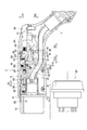
- FIG. 2 is a view showing the inside of the charging connector according to the present embodiment.
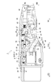
- FIG. 3 is a perspective view showing the inside of the charging connector according to the present embodiment.
- FIG. 4 is a cross-sectional view showing a part of the connector case and the cap according to the present embodiment.
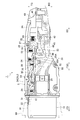
- FIG. 5 is a view for explaining the operation (detached state) of the charging connector according to this embodiment.
- FIG. 6 is a view for explaining the operation (first intermediate fitting state) of the charging connector according to the present embodiment.
- FIG. 7 is a view for explaining the operation (second intermediate fitting state) of the charging connector according to the present embodiment.
- FIG. 1 is an overall perspective view showing a charging connector according to the present embodiment.
- FIG. 2 is a view showing the inside of the charging connector according to the present embodiment.
- FIG. 3 is a perspective view showing the inside of the charging connector according to the present embodiment.
- FIG. 4 is
- FIG. 8 is a view for explaining the operation (completely fitted state) of the charging connector according to the present embodiment.
- FIG. 9 is a view for explaining the operation (first intermediate pulling-out state) of the charging connector according to the present embodiment.
- FIG. 10 is a view for explaining the operation (second intermediate pull-out state) of the charging connector according to the present embodiment.
- FIG. 11 is a perspective view showing a part of the charging connector according to the background art.
- 1 to 4 are diagrams showing a charging connector 1 according to the present embodiment.
- the vehicle side inlet 90 side (the left side in FIGS. 1 to 3 and the right side in FIG. 4) of the charging connector 1 is defined as the “front end side” and heads toward this front end side.
- the direction is defined as “fitting direction FD”.
- the side opposite to the vehicle-side inlet 90 side of the charging connector 1 (the right side in FIGS. 1 to 3 and the left side in FIG. 4) is referred to as “rear end side”, and the direction toward this rear end side is referred to as “separation direction SD”.
- the charging connector 1 is fitted to a vehicle-side inlet 90 (see FIG. 2) provided with a receiving-side terminal (not shown), and is used to supply power to a vehicle battery. Is.
- the charging connector 1 is attached to the tip of an electric wire W (not shown) that extends from a power supply device (not shown).
- the charging connector 1 includes connector cases 3A and 3B as two substantially mirror-symmetrical divided bodies in which the end faces are combined.
- the connector cases 3 ⁇ / b> A and 3 ⁇ / b> B have a case main body 5 and a handle 7 that is inclined from the rear of the case main body 5 and is gripped by an operator.
- FIG. 2 shows a state in which the connector case 3B is removed from the charging connector 1 and the charging connector 1 is viewed from a direction perpendicular to the mirror image symmetry plane of the connector cases 3A and 3B.
- the connector cases 3A and 3B are formed as two substantially mirror-symmetric divided bodies in which the end faces are combined with each other.
- the connector cases 3A and 3B may be combined to form the exterior of the charging connector 1, and are not strictly limited. Need not be mirror-image symmetric.
- a connector fitting portion 10 that is fitted to the vehicle side inlet 90 is provided in front of the case main body portion 5.
- a notch 11 is formed on the outer peripheral surface of the connector fitting portion 10.
- a supply-side terminal (not shown) connected to a receiving-side terminal (not shown) in the vehicle-side inlet 90 is housed inside the connector fitting portion 10. Note that the arrangement and the like of the supply side terminals (not shown) conform to various standards and will not be described here.
- a through hole 6 is formed on the front end side of the case body 5.
- the through-hole 6 includes a cap insertion portion 6A to which a cap 9 that closes the through-hole 6 is mounted, and an axial core insertion portion 6B into which a lock release portion 24 of the lock arm 20 described later is inserted.
- the size and contour shape of the through-hole 6 are the size of each of the cap 9 and the lock release portion 24 in order to prevent entry of foreign matters (dust, water, etc.). It is preferable that it is almost equivalent to the contour shape.
- the shape of the cap 9 can be set as appropriate, and may be any shape as long as the cap insertion portion 6A can be sealed, for example, a columnar body or a truncated cone shape.
- the distal end portion of the lock release portion 24 protrudes or is exposed from the shaft core insertion portion 6B into the through-hole 6 so that the shaft core is inserted.
- the gap between the part 6B and the unlocking part 24 is sealed. Therefore, foreign matters (dust, water, etc.) are prevented from entering the connector cases 3A, 3B via the shaft core insertion portion 6B of the through hole 6. Further, the jig is prevented from being inserted into the connector cases 3A and 3B from the shaft core insertion portion 6B of the through hole 6.
- the lock release part 24 is arrange
- FIG. 4 is a cross-sectional view showing a part of the connector case 3B and the cap 9.
- FIG. 4 shows a cross section of the connector cases 3A and 3B on a plane perpendicular to the mirror image symmetry plane and parallel to the fitting direction FD.
- a locking portion 9A is provided on the peripheral wall of the cap 9, and a locked portion 6C on which the locking portion 9A is locked is provided on the side wall of the cap insertion portion 6A.
- the cap 9 is a detachable type that closes the through hole 6 and the cap insertion portion 6A by being fitted into the cap insertion portion 6A.
- the cap 9 is not necessarily detachable, and may be, for example, a screw-in type that is screwed into the cap insertion part 6A, or an open / close type that opens and closes with respect to the cap insertion part 6A.
- the through hole 6 and the cap insertion portion 6A are closed, so that foreign matter (dust, water, etc.) can be prevented from entering the through hole 6. Further, foreign matter (dust, water, etc.) is prevented from accumulating on the unlocking portion 24 arranged so as to protrude or be exposed in the through hole 6.
- An electric wire W extending from the connector fitting portion 10 is arranged on the lower side of the case main body 5 and the electric wire W passes through the handle portion 7 and is drawn to the outside.
- a lock arm 20, a fitting detection arm 30, a release lever 40, and a lever holding arm 50 are provided on the upper side in the case body 5.
- the lock arm 20 prevents the charging connector 1 from being detached from the vehicle-side inlet 90 in a fitted state between the vehicle-side inlet 90 and the connector fitting portion 10.
- the lock arm 20 includes a main arm 21 that is swingable about an axis 21 ⁇ / b> J in the case body 5, and a lock auxiliary arm 26 that swings together with the main arm 21. Consists of.
- the main arm 21 is provided on the distal end side of the main arm 21, and has a lock claw 22 as a lock claw that can be protruded and retracted from the notch 11 of the connector fitting portion 10, and the main arm 21.
- a lock engagement piece 23 as an engagement portion provided at a rear end of the release lever 40 and engaged with a lower engagement groove portion 46 described later of the release lever 40, and the main arm 21 is operated from the outside of the case body portion 5 to the release position. And a possible unlocking portion 24.
- the main arm 21 has a lock position where the lock claw 22 is engaged with an engagement groove 91 (see FIG. 2) provided on the inner peripheral surface of the vehicle-side inlet 90, and the engagement between the lock claw 22 and the engagement groove 91. It is provided so as to be swingable around a shaft core 21J as a swing shaft between an unlocked position (release position) at which is released.
- the main arm 21 is biased in a direction (upward direction TD) in which the lock claw 22 protrudes from the notch 11 of the connector fitting portion 10 by a coil spring 25 as a biasing member.
- the main arm 21 is bent in the downward direction BD near the release lever 40.
- a lock engagement piece 23 is provided at the tip of the bent lower end along the detaching direction SD.
- the lock engagement piece 23 engages with a lower engagement groove portion 46 (to be described later) of the release lever 40 when the main arm 21 is in the unlocked position (that is, when the lock claw 22 is retracted into the notch 11). On the other hand, the lock engagement piece 23 is disengaged from the later-described upper locking groove portion 45 of the release lever 40 at the lock position of the main arm 21 (that is, the lock claw 22 protrudes from the notch 11).
- the lock release portion 24 is inserted into the through hole 6 formed in the case main body portion 5. That is, the lock release part 24 is provided in the cap insertion part 6 ⁇ / b> A that forms the through hole 6.
- the lock release portion 24 is configured by the shaft core 21J of the main arm 21 on the connector case 3B side.
- the shaft core 21J is formed with a jig insertion hole 24A into which a jig (not shown) such as a hexagon wrench is inserted.
- the lock auxiliary arm 26 includes an auxiliary locking piece 27 that is provided at the rear end of the lock auxiliary arm 26 and locks in an upper locking groove portion 45 described later of the release lever 40. Yes.
- the lock auxiliary arm 26 is released from the locking position where the auxiliary locking piece 27 is locked to an upper locking groove 45 described later of the release lever 40 and the locking between the auxiliary locking piece 27 and the upper locking groove 45. It is provided so as to be swingable with respect to the main arm 21 around an axis 26A provided on the main arm 21 between the non-locking position (release position).
- the lock auxiliary arm 26 is urged by the coil spring 28 in the locking direction (downward direction BD) of the auxiliary locking piece 27.
- One end of the coil spring 28 is fixed to a position on the rear end side of the main arm 21 with respect to the shaft core 21J, and the other end is fixed to a position on the front end side of the lock auxiliary arm 26 with respect to the shaft core 26A.
- the main arm 21 and the lock auxiliary arm 26 remain in a relative positional relationship due to the restoring force of the coil spring 28.
- the shaft core 21J is swingably provided.
- the auxiliary locking piece 27 extends in the downward direction BD, and is provided so as to be locked in an upper locking groove portion 45 described later of the release lever 40.
- the auxiliary locking piece 27 is provided at a position facing the lock engagement piece 23 described above.
- the auxiliary locking piece 27 is provided on the side of the detachment direction SD with respect to a detection locking piece 32 described later of the fitting detection arm 30 and a holding locking piece 51 described later of the lever holding arm 50.
- the fitting detection arm 30 detects a complete fitting state between the vehicle side inlet 90 and the connector fitting portion 10. As shown in FIGS. 2 and 3, the fitting detection arm 30 is fitted with a detection claw 31 that is provided on the distal end side of the fitting detection arm 30 and can be protruded and retracted from the notch 11 of the connector fitting portion 10. And a detection locking piece 32 that is provided on the rear end side of the detection arm 30 and locks in an upper locking groove portion 45 of the release lever 40 described later.
- the fitting detection arm 30 includes a fitting position where the detection claw 31 comes into contact with the front end surface of the vehicle side inlet 90 to detect the fitting of the connector fitting portion 10 to the vehicle side inlet 90, and the detection claw 31 and the vehicle side. It is provided so as to be swingable around the shaft core 33 between the release position where the contact with the inlet 90 is released and the removal of the connector fitting portion 10 from the vehicle side inlet 90 is detected.
- the fitting detection arm 30 is biased by a coil spring 34 in a direction in which the detection claw 31 protrudes into the notch 11 of the connector fitting portion 10 (that is, the locking direction of the detection locking piece 32).
- the detection claw 31 is provided so as to be able to appear and retract (moving forward and backward) from the notch 11 of the connector fitting portion 10 to the outside.
- the detection claw 31 is provided on the detachment direction SD side with respect to the lock claw 22 of the main arm 21 described above.
- the detection locking piece 32 extends in the downward direction BD and is provided so as to be locked in an upper locking groove portion 45 described later of the release lever 40.
- the detection locking piece 32 is provided closer to the fitting direction FD than the auxiliary locking piece 27 of the lock auxiliary arm 26, and is provided closer to the disengagement direction SD than the holding locking piece 51 described later of the lever holding arm 50. Yes.
- the fitting detection arm 30 swings around the shaft core 33.
- the detection locking piece 32 is unlocked from an upper locking groove 45 described later of the release lever 40.
- the connector fitting portion 10 is disengaged (that is, the detection claw 31 protrudes from the notch 11 of the connector fitting portion 10)
- the fitting detection arm 30 swings around the shaft core 33.
- the detection locking piece 32 is locked with an upper locking groove portion 45 described later of the release lever 40.
- a projection 35 (see FIGS. 2 and 3) that protrudes in the downward direction BD is provided.
- the protrusion 35 presses the distal end side of the lever holding arm 50 (the distal end side with respect to the shaft core 52 described later) in the downward direction BD, whereby the upper locking groove portion 45 described later of the release lever 40 and the lever holding arm are pressed. 50 is unlocked with a holding latch piece 51 described later.
- the release lever 40 releases the engagement between the engagement groove 91 in the vehicle-side inlet 90 and the lock claw 22.
- the release lever 40 is provided so as to be slidable from the start position to the completion position of the pushing operation with respect to the case body 5 (that is, the fitting / removing direction FSD).
- the release lever 40 is provided in the case body 5 with a release switch 41 whose rear end protrudes from the case body 5 and moves in the fitting / removing direction FSD.
- a release main body 42 formed integrally with the switch 41 is provided.
- the release switch 41 is urged by the coil spring 43 to the start position of the push operation of the release switch 41 (that is, the detachment direction SD side).
- the release main body portion 42 includes an auxiliary locking piece 27 of the lock auxiliary arm 26, a detection locking piece 32 of the fitting detection arm 30, and a holding locking piece 51 described later of the lever holding arm 50.
- a tip abutting portion 44 that abuts and pushes up.
- the tip contact portion 44 swings the main arm 21 to the unlocked position by contacting the inclined surface 21A of the main arm 21 at the position where the release switch 41 is pushed.
- the tip contact portion 44 is formed in a curved shape.
- An auxiliary locking piece 27 of the lock auxiliary arm 26, a detection locking piece 32 of the fitting detection arm 30, and a holding locking piece 51 to be described later of the lever holding arm 50 are respectively locked on the upper end of the release main body 42.
- An upper locking groove 45 is provided.
- a lower engagement groove portion 46 as an engaged portion with which the lock engagement piece 23 of the main arm 21 is engaged is provided below the distal end of the release main body portion 42.
- the lever holding arm 50 holds the release lever 40 at the completion position of the release lever 40. As shown in FIGS. 2 and 3, the lever holding arm 50 is provided on the rear end side of the lever holding arm 50 at the pressing position of the release lever 40 and is held in the upper locking groove 45 of the release lever 40. 51 is provided.
- the lever holding arm 50 includes a lever holding position that holds the release lever 40 at the completion position (that is, a state in which the holding locking piece 51 is locked to the upper locking groove 45), and a lever non-holding position that does not hold the release lever 40. Between the holding latch piece 51 and the upper latch groove 45, the pivot is provided around the shaft core 52.
- a coil spring 53 is provided on the holding / holding piece 51 side of the axis 52 of the lever holding arm 50, and the holding / holding piece 51 side is urged by the coil spring 53 toward the downward direction BD.
- the distal end side of the lever holding arm 50 with respect to the shaft core 52 can come into contact with the protrusion 35 of the fitting detection arm 30.
- the holding locking piece 51 extends in the downward direction BD and is provided in the upper locking groove 45 of the release lever 40 so as to be locked.
- the holding locking piece 51 is provided closer to the fitting direction FD than the auxiliary locking piece 27 of the lock auxiliary arm 26 and the detection locking piece 32 of the fitting detection arm 30.
- the holding locking piece 51 is locked with the upper locking groove 45 of the release lever 40 in the lever holding position.
- the holding locking piece 51 is pressed by the projection 35 on the tip side of the lever holding arm 50 with respect to the shaft core 52, so that the upper locking groove 45 of the release lever 40 and the holding locking piece 51 The lock is released.
- the detection locking piece 32 of the fitting detection arm 30 is locked in the upper locking groove 45 of the release lever 40.
- assistant latching piece 27 is located in the removal direction SD rather than the detection latching piece 32, it is in the state which is not completely latched by the upper side locking groove part 45.
- FIG. In this state when the lock between the detection locking piece 32 and the upper locking groove 45 is released, the release main body 42 of the release switch 41 is actuated by the coil spring 43 to start the pushing operation of the release switch 41 (i.e., release).
- the auxiliary locking piece 27 is locked to the upper locking groove 45. Therefore, in the detached state of the charging connector 1 with respect to the vehicle-side inlet 90 shown in FIG. 5, the auxiliary locking piece 27 has an upper engagement when the detection locking piece 32 and the upper locking groove 45 are unlocked. It is in the state which can be immediately latched with the stop groove part 45.
- the detection claw 31 is connected to the connector claw 31 by the contact of the front end surface of the vehicle-side inlet 90. It retracts (pushes) into the notch 11 of the fitting part 10. Then, the fitting detection arm 30 swings, and the detection locking piece 32 is detached from the upper locking groove 45. At this time, since the lock engagement piece 23 is inserted into the lower engagement groove 46 of the release main body 42, the release lever 40 has not yet moved in the disengagement direction SD side (the push operation start position side). It is blocked.
- the charging connector 1 goes from the disengaged state to the fully-fitted state through the respective states in the order of the first intermediate fitting state and the second intermediate fitting state.
- the tip contact portion 44 of the release main body portion 42 contacts the inclined surface 21 ⁇ / b> A of the main arm 21, the main arm 21 swings, and the lock claw 22 is connected to the connector fitting portion 10. By being pushed into the notch 11, the main arm 21 is brought into the unlocked position.
- the auxiliary locking piece 27 of the lock auxiliary arm 26 is pushed up from the upper locking groove portion 45, and the lock engaging piece 23 is inserted into the lower engagement groove portion 46.
- the release lever 40 is held at the completion position of the push-in operation, and the first intermediate pull-out state is established in which the release lever 40 is prevented from moving toward the start position of the push-in operation.
- the fitting detection arm 30 swings and the detection claw 31 moves from the notch 11 of the connector fitting portion 10. Protruding. Then, the detection locking piece 32 is locked in the upper locking groove 45. At this time, the protrusion 35 provided on the back surface side of the fitting detection arm 30 swings the lever holding arm 50, and the holding locking piece 51 is detached from the upper locking groove portion 45 to be in the second intermediate pulling state.
- the charging connector 1 goes from the fully fitted state to the detached state through the respective states in the order of the first intermediate pulling state and the second intermediate pulling state.
- the lock arm 20 (main arm 21) is inserted into the through hole 6 formed in the connector cases 3A and 3B, and the lock arm 20 is operated from the outside of the connector cases 3A and 3B to the release position.
- the main arm 21 can be swung from the outside of the connector cases 3A and 3B so as to be in the release position even if a failure occurs in the release lever 40.
- the lock release portion 24 is inserted into the through hole 6, and the distal end portion of the lock release portion 24 protrudes into the through hole 6 from the shaft core insertion portion 6 ⁇ / b> B or is exposed, thereby locking the shaft core insertion portion 6 ⁇ / b> B and The gap between the release parts 24 is sealed.
- This sealing prevents foreign matter (such as dust and water) from entering the connector cases 3A and 3B through the shaft core insertion portion 6B of the through hole 6.
- the jig since it is not necessary to insert the jig to be inserted into the unlocking portion 24 into the connector cases 3A and 3B from the through-hole 6, the jig has various parts (for example, electric wires W and various terminals) in the connector cases 3A and 3B. ) Can also be prevented.
- the connector case 3A, 3B can be connected from the outside.
- the arm 21 can be swung so as to be in the release position, and the jig can be prevented from touching various components in the connector cases 3A and 3B.
- the lock release portion 24 is configured by the shaft core 21J (swing shaft) provided on the main arm 21 of the lock arm 20, so that the lock release portion 24 needs to be provided separately from the shaft core 21J. Therefore, the charging connector 1 can be reduced in weight and cost.
- the cap 9 is attached to the cap insertion portion 6A formed around the through-hole 6, and the cap 9 closes the through-hole 6, thereby preventing erroneous operation of the charging connector 1 at normal time. Foreign matter can be prevented from entering the cap insertion portion 6A and the jig insertion hole 24A of the shaft core 21J, and the lock release portion 24 is not exposed, and the appearance is excellent.
- a locking portion 9A is provided on the peripheral wall of the cap 9, and a locked portion 6C is provided on the side wall of the cap insertion portion 6A. That is, the cap 9 is a detachable type that closes the through hole 6 and the cap insertion portion 6A by being fitted into the cap insertion portion 6A. Thereby, mounting
- the locking portion 9A is provided on the peripheral wall of the cap 9, and the locked portion 6C is provided on the side wall of the cap insertion portion 6A of the through hole 6. Even if the engaging portion is provided and the engaging portion is provided in the through hole 6, the same effect can be obtained.
- the embodiment of the present invention can be modified as follows.
- the charging connector 1 has been described as being used to supply power to the battery of the vehicle.
- the charging connector 1 is not limited to this, and is mounted on the movement of ships other than the vehicle, submarines, airplanes, and the like.
- the present invention can also be applied to an inlet of a power storage device, an inlet of a power storage device installed in a home, a building, a factory, or the like.
- the unlocking portion 24 is constituted by the shaft core 21J of the main arm 21, the present invention is not limited to this.
- the lock claw 22 is pushed closer to the lock claw 22 of the main arm 21. May be possible.
- the through-hole 6 was demonstrated as what was comprised by 6 A of cap insertion parts, and the shaft center insertion part 6B, it is not limited to this, You may be comprised only by the shaft center insertion part 6B. .
- cap 9 has been described as being attached to the shaft core insertion portion 6B, it is not limited to this and may not be provided.
- the lock arm includes a lock release portion that can operate the lock arm to the release position from the outside of the connector case. Therefore, the lock arm can be swung so as to be in the release position. Moreover, it can prevent that a foreign material penetrate
Abstract
Description
まず、本実施形態に係る充電コネクタ1の構成について、図面を参照しながら説明する。図1~図4は、本実施形態に係る充電コネクタ1を示す図である。 (Configuration of charging connector)
First, the configuration of the
ロックアーム20は、車両側インレット90とコネクタ嵌合部10との嵌合状態で、車両側インレット90からの充電コネクタ1の離脱を阻止している。図2及び図3に示すように、ロックアーム20は、ケース本体部5内で軸芯21Jを中心に揺動自在に設けられるメインアーム21と、メインアーム21とともに揺動するロック補助アーム26とによって構成される。 (Lock arm)
The
嵌合検知アーム30は、車両側インレット90とコネクタ嵌合部10との完全嵌合状態を検知している。嵌合検知アーム30は、図2及び図3に示すように、嵌合検知アーム30の先端側に設けられてコネクタ嵌合部10の切り欠き11から出没自在である検知爪31と、嵌合検知アーム30の後端側に設けられて後述する解除レバー40の後述する上側係止溝部45に係止する検知係止片32とを備えている。 (Mating detection arm)
The
解除レバー40は、車両側インレット90内の係止溝部91とロック爪22との係止を解除する。解除レバー40は、ケース本体部5に対する押込操作の開始位置から完了位置まで(すなわち、嵌合離脱方向FSD)にスライド自在に設けられている。 (Release lever)
The
レバー保持アーム50は、解除レバー40の完了位置で解除レバー40を保持する。レバー保持アーム50は、図2及び図3に示すように、レバー保持アーム50の後端側に、解除レバー40の押圧位置で解除レバー40の上側係止溝部45に係止する保持係止片51を備えている。 (Lever holding arm)
The
次に、上述した充電コネクタ1の動作について、図面を参照しながら説明する。図5~図10は、本実施形態に係る充電コネクタ1の動作を説明するための図である。 (Charge connector operation)
Next, the operation of the above-described
図5に示すように、車両側インレット90に対する充電コネクタ1の離脱状態では、メインアーム21のロック爪22と嵌合検知アーム30の検知爪31とは、それぞれコイルバネ25、コイルバネ34の付勢により、コネクタ嵌合部10の切り欠き11から突出している。 (Insertion operation)
As shown in FIG. 5, when the charging
図9に示すように、車両に搭載されるバッテリー(不図示)への充電が終了して車両側インレット90から充電コネクタ1を取り外すときは、解除レバー40の解除スイッチ41を押込操作(嵌合方向FD側に押圧)する。 (Pullout operation)
As shown in FIG. 9, when charging to a battery (not shown) mounted on the vehicle is completed and the charging
以上説明した本実施形態では、ロックアーム20(メインアーム21)が、コネクタケース3A,3Bに形成された貫通孔6内に挿入されコネクタケース3A,3Bの外部からロックアーム20を解除位置に操作可能なロック解除部24を備えることで、解除レバー40に不具合が生じた場合であっても、コネクタケース3A,3Bの外部からメインアーム21を解除位置となるように揺動させることができる。 (Action / Effect)
In the present embodiment described above, the lock arm 20 (main arm 21) is inserted into the through
上述したように、本発明の実施形態を通じて本発明の内容を開示したが、この開示の一部をなす論述及び図面は、本発明を限定するものであると理解すべきではない。この開示から当業者には様々な代替実施の形態、実施例及び運用技術が明らかとなる。 (Other embodiments)
Although the contents of the present invention have been disclosed through the embodiments of the present invention as described above, it should not be understood that the descriptions and drawings constituting a part of this disclosure limit the present invention. From this disclosure, various alternative embodiments, examples, and operational techniques will be apparent to those skilled in the art.
3A,3B コネクタケース
5 ケース本体部
6 貫通孔
6A キャップ挿入部
6B 軸芯挿入部
6C 被係止部
7 ハンドル部
9 キャップ
9A 係止部
10 コネクタ嵌合部
20 ロックアーム
21 メインアーム
21J 軸芯(揺動軸)
22 ロック爪
24 ロック解除部
25 コイルバネ
30 嵌合検知アーム
40 解除レバー
50 レバー保持アーム
90 車両側インレット(相手側コネクタ) DESCRIPTION OF
22
Claims (4)
- 相手側コネクタに嵌合するコネクタ嵌合部を収容するコネクタケースと、
先端に前記コネクタ嵌合部の外周面から出没可能なロック爪が設けられ、前記相手側コネクタに前記ロック爪が係合するロック位置と前記相手側コネクタと前記ロック爪との係合が解除される解除位置との間で揺動軸を中心に揺動するロックアームと、
前記ロックアームを前記ロック位置に向けて付勢する付勢部材と、
を備える充電コネクタであって、
前記ロックアームは、前記コネクタケースに形成された貫通孔内に挿入され前記コネクタケースの外部から前記ロックアームを解除位置に操作可能なロック解除部を備えることを特徴とする充電コネクタ。 A connector case that houses a connector fitting portion that fits into a mating connector;
A lock claw that can protrude and retract from the outer peripheral surface of the connector fitting portion is provided at the tip, and the lock position where the lock claw engages with the mating connector and the engagement between the mating connector and the lock claw are released. A lock arm that swings about the swing axis between the release position and
A biasing member that biases the lock arm toward the lock position;
A charging connector comprising:
The charging connector includes a lock releasing portion that is inserted into a through-hole formed in the connector case and is operable to move the lock arm to a release position from the outside of the connector case. - 請求項1に記載の充電コネクタであって、
前記ロック解除部は、前記ロックアームの前記揺動軸により構成されること
を特徴とする充電コネクタ。 The charging connector according to claim 1,
The charging connector according to claim 1, wherein the lock release unit is configured by the swing shaft of the lock arm. - 請求項1又は請求項2に記載の充電コネクタであって、
前記貫通孔には、前記貫通孔を塞ぐキャップが装着されること
を特徴とする充電コネクタ。 The charging connector according to claim 1 or 2, wherein
The charging connector, wherein a cap that closes the through hole is attached to the through hole. - 請求項3に記載の充電コネクタであって、
前記貫通孔及び前記キャップの何れか一方には、係止部が設けられ、他方には、前記係止部が係止される被係止部が設けられること
を特徴とする充電コネクタ。 The charging connector according to claim 3,
One of the said through-hole and the said cap is provided with the latching | locking part, and the other is provided with the to-be-latched part by which the said latching | locking part is latched.
Priority Applications (4)
| Application Number | Priority Date | Filing Date | Title |
|---|---|---|---|
| EP14774923.8A EP2980926B1 (en) | 2013-03-28 | 2014-03-25 | Charging connector |
| CN201480017306.6A CN105103385B (en) | 2013-03-28 | 2014-03-25 | Charging connector |
| JP2015508543A JP5945067B2 (en) | 2013-03-28 | 2014-03-25 | Charging connector |
| US14/863,809 US9509095B2 (en) | 2013-03-28 | 2015-09-24 | Charging connector |
Applications Claiming Priority (2)
| Application Number | Priority Date | Filing Date | Title |
|---|---|---|---|
| JP2013-069004 | 2013-03-28 | ||
| JP2013069004 | 2013-03-28 |
Related Child Applications (1)
| Application Number | Title | Priority Date | Filing Date |
|---|---|---|---|
| US14/863,809 Continuation US9509095B2 (en) | 2013-03-28 | 2015-09-24 | Charging connector |
Publications (1)
| Publication Number | Publication Date |
|---|---|
| WO2014157196A1 true WO2014157196A1 (en) | 2014-10-02 |
Family
ID=51624165
Family Applications (1)
| Application Number | Title | Priority Date | Filing Date |
|---|---|---|---|
| PCT/JP2014/058272 WO2014157196A1 (en) | 2013-03-28 | 2014-03-25 | Charging connector |
Country Status (5)
| Country | Link |
|---|---|
| US (1) | US9509095B2 (en) |
| EP (1) | EP2980926B1 (en) |
| JP (1) | JP5945067B2 (en) |
| CN (1) | CN105103385B (en) |
| WO (1) | WO2014157196A1 (en) |
Cited By (1)
| Publication number | Priority date | Publication date | Assignee | Title |
|---|---|---|---|---|
| JP2016184554A (en) * | 2015-03-26 | 2016-10-20 | 住電機器システム株式会社 | Charge connector |
Families Citing this family (15)
| Publication number | Priority date | Publication date | Assignee | Title |
|---|---|---|---|---|
| WO2014157196A1 (en) * | 2013-03-28 | 2014-10-02 | 矢崎総業株式会社 | Charging connector |
| JP6009528B2 (en) * | 2014-12-18 | 2016-10-19 | 住友電装株式会社 | Charging inlet |
| DE102015113875A1 (en) * | 2015-08-21 | 2017-02-23 | Phoenix Contact E-Mobility Gmbh | Connector part with a locking element |
| CN105421900B (en) * | 2015-12-02 | 2018-04-24 | 上海挚达科技发展有限公司 | A kind of electronic lock for charging gun and the charging gun with the electronic lock |
| DE102016105371A1 (en) * | 2016-03-22 | 2017-09-28 | Phoenix Contact E-Mobility Gmbh | Connector part for plug-in connection with a mating connector part |
| US10014615B2 (en) * | 2016-09-19 | 2018-07-03 | Lear Corporation | Connector assemblies for vehicle charging |
| US20190267758A1 (en) * | 2016-11-30 | 2019-08-29 | Lg Innotek Co., Ltd. | Electricity charging plug device, electricity charging connection device, electricity charging device and electric vehicle |
| CN108666811B (en) * | 2017-03-27 | 2024-03-12 | 汪志强 | Locking device of charging gun and charging device |
| JP6819515B2 (en) * | 2017-08-29 | 2021-01-27 | トヨタ自動車株式会社 | vehicle |
| CN108039616B (en) * | 2017-11-13 | 2019-05-21 | 中国航空工业集团公司西安航空计算技术研究所 | A kind of quick-speed plug device |
| DE102018100825B4 (en) * | 2018-01-16 | 2019-09-05 | Dr. Ing. H.C. F. Porsche Aktiengesellschaft | Landside electric vehicle charging plug |
| DE102018131610A1 (en) * | 2018-12-10 | 2020-06-10 | Phoenix Contact E-Mobility Gmbh | Charging plug with a detent connection detection |
| US11139616B2 (en) * | 2020-02-17 | 2021-10-05 | Japan Aviation Electronics Industry, Limited | Charging connector |
| CN114552277A (en) * | 2020-11-24 | 2022-05-27 | 台达电子工业股份有限公司 | Charging gun |
| US20220219630A1 (en) * | 2021-01-12 | 2022-07-14 | Ford Global Technologies, Llc | Vehicle roof rail integrated power outlet systems |
Citations (5)
| Publication number | Priority date | Publication date | Assignee | Title |
|---|---|---|---|---|
| JP2011238533A (en) * | 2010-05-12 | 2011-11-24 | Tokai Rika Co Ltd | Structure for manually releasing locking of power supply plug lock device |
| JP2012234775A (en) | 2011-05-09 | 2012-11-29 | Sumiden Asahi Industries Ltd | Charge connector |
| JP2012243687A (en) * | 2011-05-23 | 2012-12-10 | Sumiden Asahi Industries Ltd | Charge connector |
| JP2013008465A (en) * | 2011-06-22 | 2013-01-10 | Daiden Co Ltd | Feeding connector |
| JP2013149384A (en) * | 2012-01-17 | 2013-08-01 | Yazaki Corp | Electric connector |
Family Cites Families (93)
| Publication number | Priority date | Publication date | Assignee | Title |
|---|---|---|---|---|
| JP3042816B2 (en) * | 1992-12-18 | 2000-05-22 | 矢崎総業株式会社 | Power supply connector |
| JP2978348B2 (en) * | 1992-12-18 | 1999-11-15 | 矢崎総業株式会社 | Power supply connector |
| JP3316049B2 (en) * | 1993-06-14 | 2002-08-19 | 住友電装株式会社 | Electric vehicle charging device |
| US5458496A (en) * | 1993-07-12 | 1995-10-17 | Sumitomo Wiring Systems, Ltd. | Charge coupling for electric vehicle |
| JP2752032B2 (en) * | 1993-09-20 | 1998-05-18 | 矢崎総業株式会社 | Power supply connector |
| JP2879810B2 (en) * | 1993-12-28 | 1999-04-05 | 矢崎総業株式会社 | connector |
| JP3433432B2 (en) * | 1993-12-28 | 2003-08-04 | 矢崎総業株式会社 | Power supply connector |
| JP2921640B2 (en) * | 1994-03-17 | 1999-07-19 | 矢崎総業株式会社 | Power supply connector |
| JP3463820B2 (en) * | 1994-04-01 | 2003-11-05 | 矢崎総業株式会社 | Power supply connector |
| JP2904024B2 (en) * | 1994-08-08 | 1999-06-14 | 住友電装株式会社 | Electric vehicle charging connector |
| DE19544942C2 (en) * | 1994-12-01 | 2001-12-06 | Yazaki Corp | Connecting device with a voltage supply connector and a voltage receiving connector and method for connecting / disconnecting a voltage supply device |
| JP3135040B2 (en) * | 1995-11-30 | 2001-02-13 | 矢崎総業株式会社 | Electric vehicle charging connector |
| JPH09161882A (en) * | 1995-12-06 | 1997-06-20 | Yazaki Corp | Charging connector for electric vehicle |
| JP3292278B2 (en) * | 1995-12-06 | 2002-06-17 | 矢崎総業株式会社 | Electric vehicle charging connector |
| JP3262203B2 (en) * | 1996-02-16 | 2002-03-04 | 矢崎総業株式会社 | Low insertion / extraction force connector |
| JPH10112349A (en) * | 1996-10-04 | 1998-04-28 | Yazaki Corp | Charging connector for electric vehicle |
| US6371768B1 (en) * | 1998-03-31 | 2002-04-16 | Daimlerchrysler Corporation | Universal charge port connector for electric vehicles |
| US6203355B1 (en) * | 1998-03-31 | 2001-03-20 | Daimlerchrysler Corporation | Universal charge port connector for electric vehicles |
| US6225153B1 (en) * | 1999-03-24 | 2001-05-01 | Daimlerchrysler Corporation | Universal charge port connector for electric vehicles |
| EP1687872A1 (en) * | 2003-11-07 | 2006-08-09 | Fci | Connector system with improved unplugging functionality |
| NL1024850C2 (en) | 2003-11-24 | 2005-05-26 | Framatome Connectors Int | Cable connector system in telecom application, has spring to exert biasing force on locking arm after rotating lock arm to unlocked position, so that locking arm is not rotated backwards to locked position |
| JP5123144B2 (en) | 2008-11-21 | 2013-01-16 | 矢崎総業株式会社 | Charging connector |
| JP5312214B2 (en) * | 2009-06-11 | 2013-10-09 | 矢崎総業株式会社 | Lever-type electrical connector with misoperation prevention |
| US7963793B2 (en) * | 2009-09-24 | 2011-06-21 | Lear Corporation | Hybrid/electric vehicle charge handle latch mechanism |
| JP5231381B2 (en) * | 2009-11-17 | 2013-07-10 | 株式会社東海理化電機製作所 | Connector lock structure for battery charging power receiving connector |
| JP4872032B2 (en) * | 2009-12-28 | 2012-02-08 | 株式会社フジクラ | Power supply connector |
| JP5393440B2 (en) * | 2009-12-28 | 2014-01-22 | 株式会社フジクラ | Power supply connector |
| US8016607B2 (en) * | 2010-01-08 | 2011-09-13 | Lear Corporation | Connector assembly for electric vehicle charging |
| JP5482295B2 (en) * | 2010-03-01 | 2014-05-07 | 住友電装株式会社 | Charging connector |
| JP5447962B2 (en) * | 2010-02-19 | 2014-03-19 | 住友電装株式会社 | Charging connector |
| JP5392151B2 (en) * | 2010-03-09 | 2014-01-22 | 住友電装株式会社 | Charging connector |
| JP5504987B2 (en) * | 2010-03-11 | 2014-05-28 | 住友電装株式会社 | Charging connector |
| JP2011198566A (en) * | 2010-03-18 | 2011-10-06 | Sumitomo Wiring Syst Ltd | Charging connector |
| JP5096518B2 (en) * | 2010-05-12 | 2012-12-12 | 株式会社東海理化電機製作所 | Power supply plug lock device |
| JP5411059B2 (en) * | 2010-05-18 | 2014-02-12 | 株式会社東海理化電機製作所 | Charging inlet device |
| US8075329B1 (en) * | 2010-06-08 | 2011-12-13 | Ford Global Technologies, Llc | Method and system for preventing disengagement between an electrical plug and a charge port on an electric vehicle |
| JP5471890B2 (en) * | 2010-06-28 | 2014-04-16 | 住友電装株式会社 | Charging connector |
| US7878866B1 (en) * | 2010-07-02 | 2011-02-01 | Lear Corporation | Connector assembly for vehicle charging |
| JP5197699B2 (en) * | 2010-09-09 | 2013-05-15 | 住友電装株式会社 | Charging connector |
| JP2012080646A (en) * | 2010-09-30 | 2012-04-19 | Tokai Rika Co Ltd | Power feeding plug locking device |
| JP5890091B2 (en) * | 2010-10-29 | 2016-03-22 | 日本航空電子工業株式会社 | Electric connector, electric connector unit, and charger for electric vehicle |
| JP5739644B2 (en) * | 2010-11-02 | 2015-06-24 | 矢崎総業株式会社 | Power supply connector |
| US20120129378A1 (en) * | 2010-11-19 | 2012-05-24 | Delphi Technologies, Inc. | Battery charger having handle that includes light source that emits light through aperture in handle connector |
| US20120126747A1 (en) * | 2010-11-19 | 2012-05-24 | Delphi Technologies, Inc. | Battery charger having non-contact electrical switch |
| US8568155B2 (en) * | 2010-12-30 | 2013-10-29 | General Cable Technologies Corporation | Laminous multi-polymeric high amperage over-molded connector assembly for plug-in hybrid electric vehicle charging |
| JP5080662B2 (en) * | 2011-01-27 | 2012-11-21 | 日本航空電子工業株式会社 | connector |
| JP5625969B2 (en) * | 2011-02-04 | 2014-11-19 | 住友電装株式会社 | Charging connector |
| JP5775332B2 (en) * | 2011-03-04 | 2015-09-09 | 矢崎総業株式会社 | connector |
| JP5609725B2 (en) * | 2011-03-17 | 2014-10-22 | 住友電装株式会社 | Wire holding member |
| JP5645077B2 (en) * | 2011-03-17 | 2014-12-24 | 住友電装株式会社 | Charging connector |
| JP2012212647A (en) * | 2011-03-18 | 2012-11-01 | Tokai Rika Co Ltd | Power supply plug lock device |
| JP5650572B2 (en) * | 2011-03-29 | 2015-01-07 | 株式会社東海理化電機製作所 | Power supply plug lock device |
| DE102011002024A1 (en) * | 2011-04-13 | 2012-10-18 | Tyco Electronics Amp Gmbh | Charging plug with contactless switching device |
| JP5715879B2 (en) * | 2011-05-20 | 2015-05-13 | 矢崎総業株式会社 | Arc discharge prevention connector |
| JP5721536B2 (en) * | 2011-05-20 | 2015-05-20 | 矢崎総業株式会社 | Half-mating prevention connector |
| US8834202B2 (en) * | 2011-06-13 | 2014-09-16 | Lear Corporation | Connector assembly for vehicle charging |
| JP2013053470A (en) * | 2011-09-05 | 2013-03-21 | Tokai Rika Co Ltd | Lock device |
| JP2013053471A (en) * | 2011-09-05 | 2013-03-21 | Tokai Rika Co Ltd | Power feeding plug lock device |
| JP5970767B2 (en) * | 2011-09-27 | 2016-08-17 | 日産自動車株式会社 | Charger |
| JP5770588B2 (en) * | 2011-09-28 | 2015-08-26 | 株式会社東海理化電機製作所 | Power supply plug lock device |
| JP5648751B2 (en) * | 2011-10-11 | 2015-01-07 | 日産自動車株式会社 | Charging port lock device |
| EP2767429B1 (en) * | 2011-10-13 | 2020-02-26 | Nissan Motor Co., Ltd. | Charging port lock device |
| US9178312B2 (en) * | 2011-10-13 | 2015-11-03 | Nissan Motor Co., Ltd. | Charging port locking device |
| JP5813462B2 (en) * | 2011-10-31 | 2015-11-17 | 矢崎総業株式会社 | Connector mating structure |
| US8506315B2 (en) * | 2011-11-17 | 2013-08-13 | Schneider Electric USA, Inc. | Docking station for connector for electric vehicle charging station |
| DE102012100235B4 (en) * | 2012-01-12 | 2015-12-24 | Phoenix Contact Gmbh & Co. Kg | Cable plug with covering device |
| JP5815425B2 (en) * | 2012-01-17 | 2015-11-17 | 矢崎総業株式会社 | Electrical connector |
| JP5798934B2 (en) * | 2012-01-17 | 2015-10-21 | 矢崎総業株式会社 | Electrical connector |
| JP5815423B2 (en) * | 2012-01-17 | 2015-11-17 | 矢崎総業株式会社 | Electrical connector |
| USD697869S1 (en) | 2012-01-17 | 2014-01-21 | Yazaki Corporation | Charging connector for an electric vehicle |
| JP5815424B2 (en) * | 2012-01-17 | 2015-11-17 | 矢崎総業株式会社 | Electrical connector |
| JP5895618B2 (en) * | 2012-03-09 | 2016-03-30 | 日産自動車株式会社 | Electric vehicle charging port control device |
| JP5982897B2 (en) * | 2012-03-14 | 2016-08-31 | 日産自動車株式会社 | Electric vehicle charging port control device |
| JP5912740B2 (en) * | 2012-03-27 | 2016-04-27 | 本田技研工業株式会社 | Charging device for electric vehicle |
| JP5916476B2 (en) * | 2012-03-29 | 2016-05-11 | 古河電気工業株式会社 | Power supply connector |
| KR20130131033A (en) * | 2012-05-23 | 2013-12-03 | 엘에스전선 주식회사 | Connector of electric vehicle charger |
| JP5939927B2 (en) * | 2012-08-06 | 2016-06-22 | 矢崎総業株式会社 | Charging connector |
| WO2014033948A1 (en) * | 2012-09-03 | 2014-03-06 | 古河電気工業株式会社 | Power supply connector |
| JP6055260B2 (en) * | 2012-10-05 | 2016-12-27 | 矢崎総業株式会社 | Charging connector |
| CN104756328A (en) * | 2012-10-22 | 2015-07-01 | 古河电气工业株式会社 | Power supply connector |
| JP2014086338A (en) * | 2012-10-25 | 2014-05-12 | Yazaki Corp | Charging connector |
| JP5972391B2 (en) * | 2012-10-31 | 2016-08-17 | 古河電気工業株式会社 | Power supply connector and unlocking method of power supply connector |
| JP5878457B2 (en) * | 2012-12-13 | 2016-03-08 | 株式会社東海理化電機製作所 | Charging cable lock device |
| JP5922565B2 (en) * | 2012-12-13 | 2016-05-24 | 株式会社東海理化電機製作所 | Locking device |
| JP2014117974A (en) * | 2012-12-13 | 2014-06-30 | Tokai Rika Co Ltd | Lock device |
| JP5947202B2 (en) * | 2012-12-13 | 2016-07-06 | 株式会社東海理化電機製作所 | Locking device |
| JP5902602B2 (en) * | 2012-12-13 | 2016-04-13 | 株式会社東海理化電機製作所 | Locking device |
| JP6178071B2 (en) * | 2012-12-13 | 2017-08-09 | 株式会社東海理化電機製作所 | Locking device |
| JP6092662B2 (en) * | 2013-03-05 | 2017-03-08 | 矢崎総業株式会社 | Charging connector |
| WO2014157196A1 (en) * | 2013-03-28 | 2014-10-02 | 矢崎総業株式会社 | Charging connector |
| EP2787577A1 (en) * | 2013-04-02 | 2014-10-08 | Delphi International Operations Luxembourg S.à r.l. | Power plug |
| JP6023632B2 (en) * | 2013-04-08 | 2016-11-09 | 矢崎総業株式会社 | Charging connector |
| JP6148964B2 (en) * | 2013-10-17 | 2017-06-14 | 日本航空電子工業株式会社 | connector |
-
2014
- 2014-03-25 WO PCT/JP2014/058272 patent/WO2014157196A1/en active Application Filing
- 2014-03-25 CN CN201480017306.6A patent/CN105103385B/en active Active
- 2014-03-25 EP EP14774923.8A patent/EP2980926B1/en active Active
- 2014-03-25 JP JP2015508543A patent/JP5945067B2/en active Active
-
2015
- 2015-09-24 US US14/863,809 patent/US9509095B2/en active Active
Patent Citations (5)
| Publication number | Priority date | Publication date | Assignee | Title |
|---|---|---|---|---|
| JP2011238533A (en) * | 2010-05-12 | 2011-11-24 | Tokai Rika Co Ltd | Structure for manually releasing locking of power supply plug lock device |
| JP2012234775A (en) | 2011-05-09 | 2012-11-29 | Sumiden Asahi Industries Ltd | Charge connector |
| JP2012243687A (en) * | 2011-05-23 | 2012-12-10 | Sumiden Asahi Industries Ltd | Charge connector |
| JP2013008465A (en) * | 2011-06-22 | 2013-01-10 | Daiden Co Ltd | Feeding connector |
| JP2013149384A (en) * | 2012-01-17 | 2013-08-01 | Yazaki Corp | Electric connector |
Non-Patent Citations (1)
| Title |
|---|
| See also references of EP2980926A4 |
Cited By (1)
| Publication number | Priority date | Publication date | Assignee | Title |
|---|---|---|---|---|
| JP2016184554A (en) * | 2015-03-26 | 2016-10-20 | 住電機器システム株式会社 | Charge connector |
Also Published As
| Publication number | Publication date |
|---|---|
| CN105103385A (en) | 2015-11-25 |
| EP2980926B1 (en) | 2017-11-01 |
| EP2980926A1 (en) | 2016-02-03 |
| US9509095B2 (en) | 2016-11-29 |
| JPWO2014157196A1 (en) | 2017-02-16 |
| JP5945067B2 (en) | 2016-07-05 |
| CN105103385B (en) | 2017-02-22 |
| US20160020555A1 (en) | 2016-01-21 |
| EP2980926A4 (en) | 2016-10-26 |
Similar Documents
| Publication | Publication Date | Title |
|---|---|---|
| JP5945067B2 (en) | Charging connector | |
| JP5798935B2 (en) | Electrical connector | |
| JP5392151B2 (en) | Charging connector | |
| JP5815424B2 (en) | Electrical connector | |
| JP5503619B2 (en) | Power supply connector | |
| JP6092662B2 (en) | Charging connector | |
| JP5815425B2 (en) | Electrical connector | |
| WO2014168127A1 (en) | Charging connector | |
| JP5798934B2 (en) | Electrical connector | |
| JP5815423B2 (en) | Electrical connector | |
| JP5970399B2 (en) | Waterproof connector | |
| JP5273071B2 (en) | Charging plug | |
| JP6166083B2 (en) | Charging connector | |
| JP5725355B2 (en) | Lever type connector | |
| JP6015631B2 (en) | connector | |
| JP5718302B2 (en) | Power supply connector | |
| JP2008052974A (en) | Connector | |
| JP2014026794A (en) | Connector | |
| JP2014060055A (en) | Circuit conduction cut-off device | |
| JP2012128975A (en) | Connector |
Legal Events
| Date | Code | Title | Description |
|---|---|---|---|
| WWE | Wipo information: entry into national phase |
Ref document number: 201480017306.6 Country of ref document: CN |
|
| 121 | Ep: the epo has been informed by wipo that ep was designated in this application |
Ref document number: 14774923 Country of ref document: EP Kind code of ref document: A1 |
|
| ENP | Entry into the national phase |
Ref document number: 2015508543 Country of ref document: JP Kind code of ref document: A |
|
| NENP | Non-entry into the national phase |
Ref country code: DE |
|
| REEP | Request for entry into the european phase |
Ref document number: 2014774923 Country of ref document: EP |
|
| WWE | Wipo information: entry into national phase |
Ref document number: 2014774923 Country of ref document: EP |