EP2765242B1 - Petite pelleteuse hydraulique - Google Patents
Petite pelleteuse hydraulique Download PDFInfo
- Publication number
- EP2765242B1 EP2765242B1 EP12838024.3A EP12838024A EP2765242B1 EP 2765242 B1 EP2765242 B1 EP 2765242B1 EP 12838024 A EP12838024 A EP 12838024A EP 2765242 B1 EP2765242 B1 EP 2765242B1
- Authority
- EP
- European Patent Office
- Prior art keywords
- controller
- mounting
- operator
- seat
- plate
- Prior art date
- Legal status (The legal status is an assumption and is not a legal conclusion. Google has not performed a legal analysis and makes no representation as to the accuracy of the status listed.)
- Active
Links
- 238000010276 construction Methods 0.000 description 12
- 239000004576 sand Substances 0.000 description 5
- 238000007689 inspection Methods 0.000 description 4
- 239000000428 dust Substances 0.000 description 3
- 238000009434 installation Methods 0.000 description 2
- 230000002093 peripheral effect Effects 0.000 description 2
- 239000000725 suspension Substances 0.000 description 2
- 230000000712 assembly Effects 0.000 description 1
- 238000000429 assembly Methods 0.000 description 1
- 238000005034 decoration Methods 0.000 description 1
- 230000001419 dependent effect Effects 0.000 description 1
- 238000011161 development Methods 0.000 description 1
- 230000018109 developmental process Effects 0.000 description 1
- 238000005286 illumination Methods 0.000 description 1
- 238000000034 method Methods 0.000 description 1
- 230000000630 rising effect Effects 0.000 description 1
- XLYOFNOQVPJJNP-UHFFFAOYSA-N water Substances O XLYOFNOQVPJJNP-UHFFFAOYSA-N 0.000 description 1
Images


Classifications
-
- E—FIXED CONSTRUCTIONS
- E02—HYDRAULIC ENGINEERING; FOUNDATIONS; SOIL SHIFTING
- E02F—DREDGING; SOIL-SHIFTING
- E02F9/00—Component parts of dredgers or soil-shifting machines, not restricted to one of the kinds covered by groups E02F3/00 - E02F7/00
- E02F9/16—Cabins, platforms, or the like, for drivers
-
- B—PERFORMING OPERATIONS; TRANSPORTING
- B60—VEHICLES IN GENERAL
- B60N—SEATS SPECIALLY ADAPTED FOR VEHICLES; VEHICLE PASSENGER ACCOMMODATION NOT OTHERWISE PROVIDED FOR
- B60N2/00—Seats specially adapted for vehicles; Arrangement or mounting of seats in vehicles
- B60N2/75—Arm-rests
- B60N2/79—Adaptations for additional use of the arm-rests
-
- B—PERFORMING OPERATIONS; TRANSPORTING
- B66—HOISTING; LIFTING; HAULING
- B66C—CRANES; LOAD-ENGAGING ELEMENTS OR DEVICES FOR CRANES, CAPSTANS, WINCHES, OR TACKLES
- B66C13/00—Other constructional features or details
- B66C13/52—Details of compartments for driving engines or motors or of operator's stands or cabins
- B66C13/54—Operator's stands or cabins
-
- E—FIXED CONSTRUCTIONS
- E02—HYDRAULIC ENGINEERING; FOUNDATIONS; SOIL SHIFTING
- E02F—DREDGING; SOIL-SHIFTING
- E02F3/00—Dredgers; Soil-shifting machines
- E02F3/04—Dredgers; Soil-shifting machines mechanically-driven
- E02F3/28—Dredgers; Soil-shifting machines mechanically-driven with digging tools mounted on a dipper- or bucket-arm, i.e. there is either one arm or a pair of arms, e.g. dippers, buckets
- E02F3/30—Dredgers; Soil-shifting machines mechanically-driven with digging tools mounted on a dipper- or bucket-arm, i.e. there is either one arm or a pair of arms, e.g. dippers, buckets with a dipper-arm pivoted on a cantilever beam, i.e. boom
- E02F3/32—Dredgers; Soil-shifting machines mechanically-driven with digging tools mounted on a dipper- or bucket-arm, i.e. there is either one arm or a pair of arms, e.g. dippers, buckets with a dipper-arm pivoted on a cantilever beam, i.e. boom working downwardly and towards the machine, e.g. with backhoes
- E02F3/325—Backhoes of the miniature type
-
- E—FIXED CONSTRUCTIONS
- E02—HYDRAULIC ENGINEERING; FOUNDATIONS; SOIL SHIFTING
- E02F—DREDGING; SOIL-SHIFTING
- E02F9/00—Component parts of dredgers or soil-shifting machines, not restricted to one of the kinds covered by groups E02F3/00 - E02F7/00
- E02F9/20—Drives; Control devices
- E02F9/2004—Control mechanisms, e.g. control levers
Definitions
- the present invention relates to a construction machine in the form of a small-sized hydraulic excavator that is equipped with, for example, a controller for controlling electric equipment, such as a construction machine of a hydraulic excavator, a hydraulic crane or the like.
- the upper revolving structure is provided with a revolving frame that forms a support structure, a floor member that is provided on the revolving frame and constitutes an operator's seat mounting section at the rear side and a foot rest section at the front side on which an operator rests its feet, an operator's seat that is mounted to the operator's seat mounting section of the floor member and on which an operator is seated, and right and left operating lever assemblies that are provided at both of the right and left sides of the operator's seat for operating the working mechanism.
- An engine and various kinds of electric equipment such as illuminations, monitors, sensors and the like are mounted on the hydraulic excavator, and also a controller that controls these components is mounted thereon.
- a controller that controls these components is mounted thereon.
- the controller there is known the construction where the controller is arranged on a support base in back of the operator's seat inside a cab box forming an operator's room (for example, see, Patent Document 1).
- a space section is provided at the rear side in the cab box, and the controller is arranged on the support base that is arranged on this space section.
- the lower traveling structure is constituted such that each width dimension in the front-rear direction and in the right-left direction becomes a small value.
- the upper revolving structure is formed in a small size such that a revolving radius of the rear end section at revolving does not protrude largely from the lower traveling structure having a narrow width.
- the hydraulic excavator of this form is so-called an excavator of a rear small-revolving type, a cab box of which is also formed to be small-sized, and various kinds of equipment, components, the controller and the like are narrowly arrange in the narrow space in the cab box.
- a controller can be arranged in a position within easy reach also to an upper revolving structure in a small size to easily perform an inspection work and a repair work of the controller.
- the present invention entails a controller accommodating space that is provided in back side of the operating lever assembly and between a side surface of the equipment mounting part and the operator's seat, and a controller is mounted in the controller accommodating space to control various kinds of electric equipment.
- the controller accommodating space is in a position within easy arm's reach in a state where an operator is on the foot rest section of the floor member.
- a hydraulic excavator of a crawler type as a construction machine designated at 1 is a hydraulic excavator of a crawler type as a construction machine.
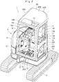
- the hydraulic excavator 1 is a small-sized hydraulic excavator that is called a mini-excavator suitable for an operation at a narrow working site.
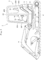
- the hydraulic excavator 1 comprises an automotive lower traveling structure 2, an upper revolving structure 3 that is mounted on the lower traveling structure 2 to be capable of revolving thereon, and a working mechanism 4 that is provided in front of the upper revolving structure 3 for performing an excavating operation of earth and sand, or the like.
- the upper revolving structure 3 has a width dimension in a right-left direction generally equal to a vehicle width of the lower traveling structure 2, is sized to be as small as to be accommodated within a revolving radius at the time the upper revolving structure 3 revolves, and is formed in a generally circular shape as viewed from above.
- the hydraulic excavator 1 is constituted as a rear small-revolving type of hydraulic excavator in which, when the upper revolving structure 3 revolves on the lower traveling structure 2, a rear surface of a counterweight 8 to be described later is accommodated substantially in the vehicle width of the lower traveling structure 2.
- the above revolving radius is defined by a distance from the revolving center of the upper revolving structure 3 to the rear surface of the counterweight 8.
- the upper revolving structure 3 is provided with a revolving frame 5 that forms a support structure, and an engine 6, a floor member 10, an operator' s seat 14, a left operating lever assembly 15, a right operating lever assembly 16, a left arm rest 17, a right arm rest 18, a controller accommodating space 21, a bracket member 22, a controller 27, and the like which are disposed on the revolving frame 5 and will be described later.
- the working mechanism 4 is mounted to the front side of the revolving frame 5 to be capable of swinging and tilting thereto. Further, two tilting support members (not shown) are provided in the left front part of the revolving frame 5 to have an interval in the right-left direction therebetween.
- a lever/pedal mounting section 13 of the floor member 10 to be described later is connected to each of the tilting support members to be capable of tilting (tilt up or tilt down).
- the engine 6 is mounted on the rear side in the revolving frame 5, and the engine 6 drives and rotates a hydraulic pump 7 (respectively shown in a dotted line of Fig. 1 ).
- the counterweight 8 is provided in the rear part of the revolving frame 5, and the counterweight 8 acts as a weight balance to the working mechanism 4, and is formed to be bent in an arc shape in such a manner as to cover a rear side of the engine 6.
- an exterior cover 9 is disposed on the revolving frame 5 to be positioned in the periphery of a cab box 20 (floor member 10) to be described later, and the exterior cover 9 covers the onboard equipment including the engine 6.
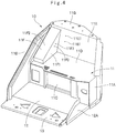
- Designated at 10 is the floor member that is disposed in a position closer to the left side on the revolving frame 5.
- the floor member 10 has a front side position that is supported in the front side position of the revolving frame 5 through the tilting support member to be capable of tilting. Therefore, the floor member 10 can tilt up/down together with the operator's seat 14, the cab box 20, which will be described later, and the like by using the front side position as a fulcrum.
- the floor member 10 is provided with an operator's seat mounting section 11, a foot rest section 12, the lever/pedal mounting section 13, and the like which will be described later.
- the operator's seat mounting section 11 is positioned at the back side of the floor member 10, and, as shown in a two-dot chain line in Fig. 3 , the operator's seat mounting section 11 is provided with the operator's seat 14, which will be described later, mounted at the upper side. As shown in Fig.
- the operator's seat mounting section 11 comprises a left side plate 11A that is installed upright in such a manner as to extend in the front-rear direction to be positioned at the left side in the right-left direction, a right side plate 11B that is installed upright in such a manner as to extend in the front-rear direction to be positioned at the right side, a laterally long front plate 11C that is installed upright from the back side of the foot rest section 12 and to close between the left side plate 11A and the right side plate 11B, a seat plate 11D that is provided to extend in the horizontal direction between the respective side plates 11A and 11B at a top part position of the front plate 11C and to which the operator's seat 14 is mounted, a back plate 11E that is inclined to a rear side from the back part of the seat plate 11D and extends upward, an equipment mounting part 11F in a triangle frame shape that rises above along the right side plate 11B from the right side of the seat plate 11D, and a mounting plate 11G that is provided to extend to the
- two screw holes 11E1 are provided in the back plate 11E to be positioned in back of the bracket member 22 to be described later.
- Bolts 26 are screwed into the two screw holes 11E1 for mounting the rear side of the controller fixing member 24 to be described later.
- the equipment mounting part 11F comprises a side surface 11F1 that is formed in a front descending triangle frame shape and rises from the seat plate 11D in a position spaced apart to the left side from the right side plate 11B, and a rectangular mounting surface 11F2 that is provided to be inclined along an inclination end edge of the side surface 11F1.
- the side surface 11F1 is provided with, for example, two screw holes 11F3 to be positioned closer to the top side at an intermediate position in the front-rear direction.
- Bolts 23 are screwed into the two screw holes 11F3 for mounting the bracket member 22 to be described later.
- the side surface 11F1 constitutes a wall surface for closing the right side of the controller accommodating space 21 to be described later. Further, operating switches of a radio, an air conditioner, and the like (none of them are shown) are mounted on the mounting surface 11F2.
- the foot rest section 12 is used for an operator seated on the operator's seat 14 to rest his or her feet on, and is provided in front of the operator's seat mounting section 11.
- the foot rest section 12 is formed as a flat plate in a rectangular shape elongated in the right-left direction.
- a left end of the foot rest section 12 that is positioned at the side of a door 20F of the cab box 20 to be described later is used as a foot step part 12A.
- the foot step part 12A is lower by one step than the foot rest section 12 in such a manner that an operator can step his or her feet thereon at the time of getting on/off the floor member 10.
- the lever/pedal mounting section 13 is provided in front of the foot rest section 12, and the lever/pedal mounting section 13 extends in the right-left direction along the front end of the foot rest section 12.
- the lever/pedal mounting section 13 is provided with an operating lever/pedal 19 and the like for traveling which will be described later.
- the operator's seat 14 is provided on the floor member 10 (see, Fig. 2 and Fig. 3 ), and the operator's seat 14 is mounted in the central position of the seat plate 11D that constitutes the operator's seat mounting section 11.
- the operator's seat 14 is used for an operator to be seated on at the time of operating the hydraulic excavator 1.
- the operator's seat 14 comprises a seat part 14A that is mounted on the seat plate 11D and on which an operator is seated, and a back rest part 14B that is installed upright from the rear portion of the seat part 14A and on which an operator rests the upper body.
- the operator's seat 14 is mounted in the central position of the seat plate 11D in the right-left direction as described above.
- the seat part 14A can be arranged in a position away in the left side from the side surface 11F1 of the equipment mounting part 11F.
- the controller accommodating space 21 to be described later can be formed between the right end of the seat part 14A and the side surface 11F1 of the equipment mounting part 11F.
- the left operating lever assembly 15 is disposed in the left side of the operator's seat 14, and comprises a console 15A that is formed in a box shape, and a lever portion 15B that is positioned in front of the console 15A and extends upward to be capable of tilting.
- This lever portion 15B is connected to a pilot valve (not shown) of a pressure reducing valve type that is provided in the console 15A.
- the right operating lever assembly 16 is disposed in the right side of the operator's seat 14, and comprises a console 16A that is formed in a box shape as substantially similar to the left operating lever assembly 15, and a lever portion 16B that is positioned in front of the console 16A and extends upward to be capable of tilting.
- This lever portion 16B is connected to a pilot valve (not shown) of a pressure reducing valve type that is provided in the console 16A.
- the right operating lever assembly 16 is arranged in a position in front of the controller 27 to be described later between the equipment mounting part 11F of the operator's seat mounting section 11 and the operator's seat 14.
- the console 16A of the right operating lever assembly 16 closes the front side of the controller accommodating space 21 to be described later.
- the left arm rest 17 is provided in back of the left operating lever assembly 15, on which a left arm of an operator operating the lever portion 15B rests, and acts to make the arm stable for performing an accurate lever operation.
- the left arm rest 17 comprises a support plate 17A that extends upside from the seat plate 11D of the operator's seat mounting section 11 constituting the floor member 10 or the console 15A of the left operating lever assembly 15, and an arm rest part 17B that is provided on a top part of the support plate 17A and on which the operator's arm can rest.
- the right arm rest 18 is provided in back side of the right operating lever assembly 16, and the right arm rest 18, as substantially similar to the left arm rest 17 described above, comprises a support plate 18A and an arm rest part 18B. As shown in Fig. 5 , the support plate 18A is mounted to the bracket member 22 to be described later.
- the traveling operating lever/pedal 19 is provided in the lever/pedal mounting section 13 forward of the operator's seat 14.
- the traveling operating lever/pedal 19 is performed by a manual operation or a foot operation of an operator at the time of traveling the lower traveling structure 2.
- the cab box 20 is provided on the floor member 10, and the cab box 20 covers the periphery of and the section above the floor member 10.
- the cab box 20 is formed in a boxy shape by a front surface 20A, a rear surface 20B, a left side surface 20C, a right side surface 20D and a top surface 20E, and a lower end portion thereof is mounted to a peripheral edge of the floor member 10.
- the cab box 20 forms an operator's room, which is an occupancy space of the operator, on the floor member 10.
- the door 20F is rotatably provided in the left side surface 20C of the cab box 20 to open/close the entrance.
- bracket member 22 the controller fixing member 24, the controller 27 and the cover member 31, which are accommodated in the controller accommodating space 21.
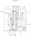
- the controller accommodating space 21 is the controller accommodating space that is provided at the right side of the operator's seat 14. As shown in Fig. 3 and Fig. 6 , the controller accommodating space 21 is a space above the seat plate 11D, and is formed between the side surface 11F1 of the equipment mounting part 11F in the operator's seat mounting section 11 and the operator's seat 14 in back side of the right operating lever assembly 16. Specifically, the controller accommodating space 21 is positioned above the seat plate 11D, and is formed as a space surrounded by the rear surface of the console 16A in the right operating lever assembly 16, the back plate 11E of the operator's seat mounting section 11, the side surface 11F1 of the equipment mounting part 11F, and the operator's seat 14.
- a part of the controller accommodating space 21 includes a U-shaped space in a transverse section, which is formed by a fixing side vertical plate 22A, a lower lateral plate 22B and an arm rest mounting vertical plate 22C of the bracket member 22 to be described later. Consequently, the controller accommodating space 21 is the space interposed between the side surface 11F1 of the equipment mounting part 11F and the operator's seat 14, including the U-shaped space of the bracket member 22.
- the controller accommodating space 21 is a space for accommodating the controller 27, and forms a flat space that is longer in the front-rear direction and in the upper-lower direction and shorter in the right-left direction.
- This controller accommodating space 21 is a place within easy arm reach in a state where an operator rests on the foot rest section 12.
- Designated at 22 is the bracket member that is provided in back side of the right operating lever assembly 16 and in the side surface 11F1 of the equipment mounting part 11F.
- the bracket member 22 is a mounting base for mounting the right arm rest 18, and forms a part of the space 21 for accommodating the controller 27. As shown in Fig. 6 , Fig. 8 , Fig. 9 and Fig.
- the bracket member 22 comprises the fixing side vertical plate 22A that extends in an upper-lower direction along the side surface 11F1 of the equipment mounting part 11F and is mounted to the side surface 11F1, the lower lateral plate 22B that extends inside (left side) toward the operator's seat 14 from a lower part of the fixing side vertical plate 22A, and an arm rest mounting vertical plate 22C that is provided to extend in an upper direction from a tip end part of the lower lateral plate 22B to oppose the fixing side vertical plate 22A to have an interval in the right-left direction therebetween.
- the bracket member 22 includes a U-shaped space in a transverse section, which is formed by the fixing side vertical plate 22A, the lower lateral plate 22B and the arm rest mounting vertical plate 22C to be opened to the upper side.
- the controller accommodating space 21 is formed to include this U-shaped space.
- Two bolt through holes 22A1 are provided at an upper part of the fixing side vertical plate 22A.
- Bolts 23 are inserted in the bolt through holes 22A1, and the bolts 23 are screwed into the screw holes 11F3 of the side surface 11F1, thus making it possible to mount the fixing side vertical plate 22A to the equipment mounting part 11F.
- a fixing member mounting frame 22D is mounted to an inner peripheral side of the fixing side vertical plate 22A opposing the arm rest mounting vertical plate 22C to extend in the horizontal direction (front-rear direction).
- Screw holes 22D1 are provided at both ends of the fixing member mounting frame 22D. As shown in Fig. 7 , bolts 25 for mounting the controller fixing member 24 are screwed into the screw holes 22D1.
- Two screw holes 22C1 are disposed in an upper part of the arm rest mounting vertical plate 22C, and bolts 33 are screwed into the screw holes 22C1 for mounting the support plate 18A of the right arm rest 18.
- cover member mounting projections 22E extending in the horizontal direction are mounted in a lower part of the arm rest mounting vertical plate 22C, and bolt through holes 22E1 are disposed at both ends of the cover member mounting projections 22E. As shown in Fig. 7 , bolts 32 are inserted into the blot through holes 22E1 for mounting the cover member 31.
- the controller fixing member 24 comprises a flat plate 24A in a substantially rectangular shape extending in the front-rear direction along the side surface 11F1 of the equipment mounting part 11F, an inclined plate 24B that extends to be bent toward a side of the operator's seat 14 from a rear end of the flat plate 24A and inclined to oppose the back plate 11E, a front-side controller mounting frame 24C that is disposed to extend in the upper-lower direction in a front position of the flat plate 24A, a rear side controller mounting frame 24D that is disposed to extend in the upper-lower direction in a rear position of the flat plate 24A, and two cover upper part mounting projections 24E and 24F that are disposed in positions in accordance with the controller mounting frames 24C and 24D respectively to protrude in a side of the
- the flat plate 24A and the inclined plate 24B covers the controller 27 to be described later in cooperation with the cover member 31 to be described later, and act also as covers for covering the right side and the rear side of the controller 27.
- two bolt through holes 24A1 are formed in a lower position of the flat plate 24A in positions in accordance with the screw holes 22D1 of the fixing member mounting frame 22D of the bracket member 22.
- the inclined plate 24B is provided with two bolt through holes 24B1 in positions in accordance with the screw holes 11E1 of the back plate 11E in the operator's seat mounting section 11. As shown in Fig.
- the controller mounting frame 24C is provided with two screw holes 24C1 in positions away from each other in the upper-lower direction for mounting the controller 27.
- the controller mounting frame 24D is provided with two screw holes 24D1 in positions away from each other in the upper-lower direction for mounting the controller 27.
- the cover upper part mounting projections 24E and 24F respectively are provided with screw holes 24E1 and 24F1 for mounting the cover member 31.
- the controller fixing member 24 as constituted in this manner causes the flat plate 24A to be in contact with the fixing member mounting frame 22D to oppose the fixing side vertical plate 22A of the bracket member 22, and the respective bolts 25 that are inserted into the respective bolt through holes 24A1 are screwed into the screw holes 22D1 of the fixing member mounting frame 22D. Consequently, the controller fixing member 24 can be mounted to the bracket member 22. Further, the controller fixing member 24 causes the inclined plate 24B to be in contact with the back plate 11E of the operator's seat mounting section 11, and the respective bolts 26 that are inserted into the respective bolt through holes 24B1 are screwed into the screw holes 11E1 of the back plate 11E, thereby making it possible to mount the inclined plate 24B on the back plate 11E.
- Designated at 27 is the controller (see Fig. 14 ) that is disposed in the controller accommodating space 21.
- This controller 27 is connected to a control device of an engine 6, and electrical components (not shown) such as various kinds of sensors and switches, and controls them in response to an operation of an operator.
- the controller 27 is constituted to cover a microcomputer (not shown) composed of many electrical components with a boxy case 28, and a harness 29 that is formed by bundling plural wires extends from a lower part of the case 28.
- a front surface portion 28A and a rear surface portion 28B of the case 28 are provided with mounting projections 28C (only three pieces are shown) in accordance with the screw holes 24C1 and 24D1 of the respective controller mounting frames 24C and 24D constituting part of the controller fixing member 24.
- the case 28 is formed in a flat rectangular parallelopiped shape (boxy shape), and is arranged to oppose the flat plate 24A of the controller fixing member 24 so as this case 28 to be installed upright.
- the respective blots 30 that are inserted into the respective mounting projections 28C are screwed into the screw holes 24C1 and 24D1 of the respective controller mounting frames 24C and 24D respectively, thus making it possible to mount the controller 27 to the controller fixing member 24.
- the controller 27 since the controller 27 is set in the vertical arrangement state, even in a case where the controller accommodating space 21 has a slight installation area in a plan view, the controller 27 can be accommodated in the controller accommodating space 21.
- the controller 27 since the controller 27 is arranged in a position higher than the seat plate 11D of the operator's seat mounting section 11 and the lower lateral plate 22B of the bracket member 22, it is possible to prevent the controller 27 from being immersed in rainwater remaining on the seat plate 11D. Further, since the controller 27 is arranged in a high position, the harness 29 can be removed from the lower side of the case 28, and the harness 29 can be easily turned around.
- the cover member 31 is disposed in the controller accommodating space 21 (see, Fig. 15 ), and the cover member 31 covers the controller 27 together with the controller fixing member 24.
- the cover member 31 is formed in a frame shape by a front surface portion 31A, a left surface portion 31B and a top surface portion 31C.
- the cover member 31, for forming a boxy shape together with the flat plate 24A and the inclined plate 24B of the controller fixing member 24, has dimensions of the respective surface portions set corresponding thereto.
- the cover member 31 is arranged to oppose the controller fixing member 24 in such a manner as to cover the controller 27.
- the respective bolts 32 that are inserted into the respective bolt through holes 22E1 of the cover member mounting projections 22E are screwed into respective screw holes 31B1 of the left surface portion 31B.
- respective bolts 32 that are inserted into respective bolt through holes 31C1 of the top surface portion 31C are screwed into the screw holes 24E1 and 24F1 of the respective cover upper part mounting projections 24E and 24F of the controller fixing member 24. Therefore, the cover member 31 can cover the controller 27 together with the controller fixing member 24 to protect the controller 27 from earth and sand, dust, rainwater, impact and the like.
- the support plate 18A of the right arm rest 18 is made to be in contact with the upper side of the arm rest mounting vertical plate 22C of the bracket member 22, and in this state, the respective bolts 33 are screwed into the respective screw holes 22C1 of the arm rest mounting vertical plate 22C. Consequently, the right arm rest 18 can be mounted to the rear side of the right operating lever assembly 16 while keeping away from the controller 27 (cover member 31).
- the bracket member 22 can be mounted to the side surface 11F1 of the equipment mounting part 11F.
- the arm rest mounting vertical plate 22C of the bracket member 22 is placed on the seat plate 11D of the operator's seat mounting section 11 to make the fixing side vertical plate 22A in contact with the side surface 11F1 of the equipment mounting part 11F.
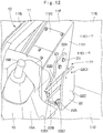
- the bolts 23 are inserted into the respective bolt through holes 22A1 of the fixing side vertical plate 22A, and the respective bolts 23 are screwed into the screw holes 11F3 of the side surface 11F1. Therefore, as shown in Fig. 12 , the bracket member 22 can be mounted to the side surface 11F1 of the equipment mounting part 11F.
- the flat plate 24A of the controller fixing member 24 is arranged between the fixing side vertical plate 22A and the arm rest mounting vertical plate 22C of the bracket member 22, the inclined plate 24B of the controller fixing member 24 is made to be in contact with the back plate 11E, and the flat plate 24A is made to be in contact with the fixing side vertical plate 22A.
- the bolts 26 are inserted into the respective bolt through holes 24B1 of the inclined plate 24B to screw the respective bolts 26 into the screw holes 11E1 of the back plate 11E.
- the bolts 25 are inserted into the respective bolt through holes 24A1 of the flat plate 24A, and the respective bolts 25 are screwed into the screw holes 22D1 of the fixing member mounting frame 22D. Consequently, as shown in Fig. 13 , the controller fixing member 24 can be mounted to the back plate 11E of the operator's seat mounting section 11 and the fixing side vertical plate 22A of the bracket member 22.
- the case 28 of the controller 27 is arranged to oppose the flat plate 24A of the controller fixing member 24.
- the bolts 30 that are inserted into the respective mounting projections 28C provided in the case 28 are screwed into the screw holes 24C1 of the controller mounting frame 24C in the controller fixing member 24 and the screw holes 24D1 of the controller mounting frame 24D respectively. Consequently, as shown in Fig. 14 , the controller 27 can be positioned in the controller accommodating space 21 to be mounted to the controller fixing member 24.
- a left surface portion 31B is inserted between the arm rest mounting vertical plate 22C and the controller 27, and the cover member 31 is arranged to cover the controller 27.
- the respective bolts 32 that are inserted into the respective bolt through holes 22E1 of the respective cover member mounting projections 22E are screwed into the respective screw holes 31B1 of the left surface portion 31B.
- the bolts 32 that are inserted into the respective bolt through holes 31C1 of the top surface portion 31C are respectively screwed into the screw hole 24E1 of the cover upper part mounting projection 24E and the screw hole 24F1 of the cover upper part mounting projection 24F, which are disposed on the controller fixing member 24. Consequently, as shown in Fig. 15 , the cover member 31 can be mounted to the bracket member 22 and the controller fixing member 24.
- the hydraulic excavator 1 according to the present embodiment has the constitution as described above, and next, an operation thereof will be explained.
- the controller accommodating space 21 is disposed in back side of the right operating lever assembly 16 between the side surface 11F1 of the equipment mounting part 11F in the operator's seat mounting section 11 and the operator's seat 14, the controller 27 that controls various kinds of electric equipment is mounted in the controller accommodating space 21.
- the controller 27 can be mounted in the controller accommodating space 21 by using the controller accommodating space 21 provided between the side surface 11F1 of the equipment mounting part 11F and the operator's seat 14 in back side of the right operating lever assembly 16.
- the position where the controller 27 is mounted is a position within easy reach in a state where an operator gets on the foot rest section 12 of the floor member 10.
- the controller 27 can be mounted also to the upper revolving structure 3 of the small-sized hydraulic excavator 1.
- the controller 27 since the controller 27 is set in a vertical arrangement state, the controller 27 can be accommodated in the controller accommodating space 21 that is a small vacant space lateral to the operator's seat 14. In this case, since the position lateral to the operator's seat 14 is a position within easy reach, a removal work, an inspection work, a repair work and the like of the controller 27 can be easily performed.
- the controller 27 is mounted to the side surface 11F1 of the equipment mounting part 11F through the bracket member 22 and the controller fixing member 24. Therefore, the controller 27 can be mounted by using the side surface 11F1 of the equipment mounting part 11F. In this case, the controller 27 can be mounted to a high position away above from the seat plate 11D. In consequence, even if rainwater remains on the seat plate 11D, it is possible to prevent the rainwater from entering into the case 28 of the controller 27. Thereby, the case 28 of the controller 27 can be formed as an inexpensive case that is low in water proof properties.
- the controller 27 can be accommodated in the controller accommodating space 21.
- the right arm rest 18 can be mounted to the arm rest mounting vertical plate 22C while keeping away from the controller 27.
- the controller fixing member 24 comprises the flat plate 24A along the side surface 11F1 of the equipment mounting part 11F, the controller mounting frames 24C and 24D disposed in the front and rear positions of the flat plate 24A, and the like.
- the controller 27 is provided with the mounting projections 28C in the front and rear positions of the case 28. Thereby, the bolts 30 that are inserted into the mounting projections 28C disposed in the case 28 of the controller 27 are screwed into the screw holes 24C1 and 24D1 of the controller mounting frames 24C and 24D of the controller fixing member 24, and therefore the controller 27 can be mounted integrally with the controller fixing member 24.
- the cover member 31 is provided in the controller fixing member 24 for covering the controller 27 between the cover member 31 and the controller fixing member 24. Consequently, the cover member 31 can protect the controller 27 from earth and sand, dust, rainwater, impact and the like.
- the present embodiment is explained by taking a case where the controller 27 is mounted to the fixing side vertical plate 22A of the bracket member 22 through the controller fixing member 24, as an example.
- the present invention may be constituted to mount the controller 27, for example, directly to the fixing side vertical plate 22A of the bracket member 22 without use of this controller fixing member 24.
- the present embodiment is explained by taking a case where the floor member 10 can tilt up/down to the revolving frame 5 by using the front side position as a fulcrum.
- the present invention is not limited thereto, and can be applied, for example, to a hydraulic excavator of a type where the floor member is provided to be fixed to the revolving frame.
- the present embodiment is explained by taking the hydraulic excavator 1 of the crawler type equipped with the cab box 20 for covering the periphery of and the section above the operator's seat 14 as an example of the construction machine.
- the present invention is not limited thereto, and may be applied to a hydraulic excavator of a crawler type equipped with a canopy for covering the section above the operator's seat 14, for example.
- the present invention may be applied to a hydraulic excavator equipped with a wheel type lower traveling structure instead of the crawler type hydraulic excavator 1.
- the present invention may be applied to the other construction machine such as a hydraulic crane.
Landscapes
- Engineering & Computer Science (AREA)
- Mining & Mineral Resources (AREA)
- Civil Engineering (AREA)
- General Engineering & Computer Science (AREA)
- Structural Engineering (AREA)
- Mechanical Engineering (AREA)
- Aviation & Aerospace Engineering (AREA)
- Transportation (AREA)
- Component Parts Of Construction Machinery (AREA)
Claims (4)
- Excavateur hydraulique de petite taille comprenant :une structure de circulation inférieure automotrice (2) ;une structure tournante supérieure (3) qui est montée sur ladite structure de circulation inférieure (2) pour être capable de tourner sur celle-ci ;un mécanisme de travail (4) qui est monté avec possibilité de basculement sur ladite structure tournante supérieure (3), etun contrepoids (8) qui est prévu dans une partie arrière de ladite structure tournante supérieure (3) pour faire office de poids d'équilibrage audit mécanisme de travail (4) et qui présente une surface arrière formée pour être cintrée sous une forme en arc, d'une manière à être logé à l'intérieur d'une largeur de ladite structure de circulation inférieure (2),dans lequel ladite structure tournante supérieure (3) inclut :un cadre tournant (5) qui forme une structure de support ;un moteur (6) qui est prévu sur ledit cadre tournant (5), et dont le côté arrière est couvert par ledit contrepoids (8) ; etun élément de plancher (10) qui est positionné sur un côté avant dudit moteur (6), prévu sur ledit cadre tournant (5), et qui constitue une section de montage (11) pour un siège d'opérateur sur le côté arrière, et une section repose-pied (12) sur le côté avant et sur lequel un opérateur repose son pied,dans lequel ladite section de montage (11) pour un siège d'opérateur dudit élément de plancher (10) inclut une plaque à siège (11D) pour monter un siège d'opérateur (14) sur lequel est assis un opérateur, et une partie de montage pour équipement (11F) qui monte vers le haut depuis un côté de ladite plaque à siège (11D) dans la direction droite/gauche, etun ensemble formant levier d'actionnement (16) qui est actionné par l'opérateur assis sur ledit siège d'opérateur (14) est prévu à l'avant de ladite partie de montage pour équipement (11F),caractérisé en ce que :il est prévu un espace de réception de contrôleur (21) dans un côté arrière dudit ensemble formant levier d'actionnement (16) et entre une surface latérale (11F1) de ladite partie de montage pour équipement (11F) et ledit siège d'opérateur (14),un contrôleur (27) est monté dans ledit espace de réception de contrôleur (21) pour commander diverses sortes d'équipement électrique,un élément de monture (22) est prévu dans un côté arrière dudit ensemble formant levier d'actionnement (16) et sur ladite surface latérale (11F1) de ladite partie de montage pour équipement (11F) pour monter ledit contrôleur (27), et un accoudoir (18) sur lequel repose un bras d'un opérateur,dans lequel ledit élément de monture (22) comprend :une plaque de fixation verticale latérale (22A) qui s'étend dans une direction vers le haut/vers le bas le long de ladite surface latérale (11F1) de ladite partie de montage pour équipement (11F) et qui est montée sur ladite surface latérale (11F1), une plaque latérale inférieure (22B) qui s'étend à l'intérieur vers ledit siège d'opérateur (14) depuis une partie inférieure de ladite plaque de fixation verticale latérale (22A), et une plaque verticale de montage pour accoudoir (22C) qui est prévue pour s'étendre dans une direction vers le haut depuis une partie terminale de ladite plaque latérale inférieure (22B) pour être opposée à ladite plaque de fixation verticale latérale (22A) avec un intervalle et sur laquelle est monté ledit accoudoir (18), etune partie dudit espace de réception de contrôleur (21) est un espace en forme de U dans une section transversale, qui est formé par ladite plaque de fixation verticale latérale (22A), par ladite plaque latérale inférieure (22B) et par ladite plaque verticale de montage pour accoudoir (22C) qui constitue ledit élément de monture (22).
- Excavateur hydraulique de petite taille selon la revendication 1, dans lequel
un élément de fixation de contrôleur (24) est prévu sur ladite plaque de fixation verticale latérale (22A) dudit élément de monture (22) pour fixer ledit contrôleur (27), dans lequel
ledit contrôleur (27) est fixé dans un état d'agencement vertical s'étendant dans une direction montante/descendante et dans une direction avant/arrière par rapport audit élément de fixation de contrôleur (24). - Excavateur hydraulique de petite taille selon la revendication 2, dans lequel
ledit élément de fixation de contrôleur (24) comprend une plaque plane (24A) qui s'étend dans une direction avant/arrière le long de ladite surface latérale (11F1) de ladite partie de montage pour équipement (11F) et une paire de cadres de montage pour contrôleur (24C, 24D) qui sont prévus respectivement à une position latérale avant et à une position latérale arrière de ladite plaque plane (24A), dans lequel
ledit contrôleur (27) est doté de projection de montage (28C) à une position latérale avant et à une position latérale arrière d'un casier (28) pour recevoir un composant électrique, et
ledit contrôleur (27) est constitué de telle façon que chacune desdites projections de montage (28C) est fixée à chacun desdits cadres de montage pour contrôleur (24C, 24D) en utilisant des boulons (30). - Excavateur hydraulique de petite taille selon la revendication 2, dans lequel
il est prévu un élément de couverture (31) pour couvrir ledit contrôleur (27), et ledit élément de couverture (31) est supporté par ledit élément de monture (22) et/ou par ledit élément de fixation pour contrôleur (24).
Applications Claiming Priority (2)
| Application Number | Priority Date | Filing Date | Title |
|---|---|---|---|
| JP2011220945 | 2011-10-05 | ||
| PCT/JP2012/075651 WO2013051609A1 (fr) | 2011-10-05 | 2012-10-03 | Engin de chantier |
Publications (3)
| Publication Number | Publication Date |
|---|---|
| EP2765242A1 EP2765242A1 (fr) | 2014-08-13 |
| EP2765242A4 EP2765242A4 (fr) | 2015-05-20 |
| EP2765242B1 true EP2765242B1 (fr) | 2018-02-28 |
Family
ID=48043763
Family Applications (1)
| Application Number | Title | Priority Date | Filing Date |
|---|---|---|---|
| EP12838024.3A Active EP2765242B1 (fr) | 2011-10-05 | 2012-10-03 | Petite pelleteuse hydraulique |
Country Status (6)
| Country | Link |
|---|---|
| US (1) | US8978812B2 (fr) |
| EP (1) | EP2765242B1 (fr) |
| JP (1) | JP5865384B2 (fr) |
| KR (1) | KR101974962B1 (fr) |
| CN (1) | CN103764920B (fr) |
| WO (1) | WO2013051609A1 (fr) |
Families Citing this family (18)
| Publication number | Priority date | Publication date | Assignee | Title |
|---|---|---|---|---|
| JP2013129996A (ja) * | 2011-12-21 | 2013-07-04 | Hitachi Constr Mach Co Ltd | 建設機械のパイロットバルブ取り付け構造 |
| JP5920313B2 (ja) * | 2013-10-29 | 2016-05-18 | コベルコ建機株式会社 | 作業機械 |
| JP6260298B2 (ja) * | 2014-01-24 | 2018-01-17 | コベルコ建機株式会社 | 建設機械 |
| JP5725636B1 (ja) | 2014-05-30 | 2015-05-27 | グラフェンプラットフォーム株式会社 | グラフェン組成物及びグラフェン成形物 |
| JPWO2016063395A1 (ja) * | 2014-10-23 | 2017-04-27 | 株式会社小松製作所 | コントローラ組立体および作業機械用キャブ |
| JP6359496B2 (ja) * | 2015-09-02 | 2018-07-18 | 株式会社日立建機ティエラ | 建設機械 |
| CN105637151B (zh) * | 2015-09-30 | 2021-03-26 | 株式会社小松制作所 | 液压挖掘机 |
| JP6585534B2 (ja) * | 2016-03-28 | 2019-10-02 | 株式会社日立建機ティエラ | 小型の油圧ショベル |
| JP6618435B2 (ja) * | 2016-07-28 | 2019-12-11 | 株式会社日立建機ティエラ | 小型油圧ショベル |
| JP1577338S (fr) * | 2016-08-30 | 2017-05-29 | ||
| DE102016011354A1 (de) * | 2016-09-20 | 2018-03-22 | Liebherr-Werk Biberach Gmbh | Steuerstand für einen Kran, Bagger und dergleichen |
| CA3060559A1 (fr) * | 2017-04-19 | 2018-10-25 | Clark Equipment Company | Cabine de chargeur |
| CN108002236A (zh) * | 2017-10-30 | 2018-05-08 | 德马科起重机械有限公司 | 一种起重机驾驶室锁定装置 |
| WO2018159860A1 (fr) * | 2018-03-26 | 2018-09-07 | 株式会社小松製作所 | Couvercle pour véhicule de travail, habitacle de véhicule de travail et véhicule de travail |
| EP3779058B1 (fr) * | 2018-03-28 | 2023-10-04 | Sumitomo (S.H.I.) Construction Machinery Co., Ltd. | Engin de chantier |
| USD969878S1 (en) * | 2019-09-30 | 2022-11-15 | Kubota Corporation | Backhoe loader |
| CN113638461A (zh) * | 2021-08-26 | 2021-11-12 | 江苏徐工工程机械研究院有限公司 | 一种狭小空间内的内饰布局方法及操纵系统 |
| JP2023033717A (ja) * | 2021-08-30 | 2023-03-13 | ヤンマーホールディングス株式会社 | 作業機械 |
Family Cites Families (18)
| Publication number | Priority date | Publication date | Assignee | Title |
|---|---|---|---|---|
| US4646869A (en) * | 1985-07-29 | 1987-03-03 | Dresser Industries, Inc. | Adjustable control console |
| JPH0725292A (ja) | 1993-07-14 | 1995-01-27 | Iseki & Co Ltd | トラクタのスイッチボックス |
| US6170588B1 (en) * | 1997-06-03 | 2001-01-09 | Hitachi Construction Machinery Co., Ltd. | Revolving construction machine |
| JP3772545B2 (ja) * | 1998-08-20 | 2006-05-10 | 日立建機株式会社 | 建設機械の運転席ユニット |
| JP2000170209A (ja) | 1998-12-04 | 2000-06-20 | Hitachi Constr Mach Co Ltd | 建設機械用キャブ |
| JP2001098953A (ja) | 1999-09-30 | 2001-04-10 | Hokuetsu Kogyo Co Ltd | 防音型エンジン作業機の電装品収納構造 |
| EP1491393B1 (fr) * | 2003-06-23 | 2006-10-25 | Caterpillar Inc. | Appareil et méthode de contrôle d'une machine |
| JP4188799B2 (ja) | 2003-10-17 | 2008-11-26 | 日立建機株式会社 | 建設機械 |
| US7287810B2 (en) | 2003-10-14 | 2007-10-30 | Hitachi Construction Machinery Co., Ltd. | Construction machine |
| JP2006077544A (ja) * | 2004-09-13 | 2006-03-23 | Hitachi Constr Mach Co Ltd | 建設機械の運転席装置 |
| US7121608B2 (en) * | 2004-09-23 | 2006-10-17 | Crown Equipment Corporation | Rotating and/or swiveling seat |
| US7757806B2 (en) * | 2005-12-22 | 2010-07-20 | Caterpillar Sarl | Adjustable operator interface |
| EP2088249B1 (fr) * | 2006-11-28 | 2011-08-31 | Hitachi Construction Machinery Co., Ltd | Machine de construction |
| US7857090B2 (en) * | 2008-03-07 | 2010-12-28 | Deere & Company | Auxiliary input arrangement |
| US7878288B2 (en) * | 2008-03-14 | 2011-02-01 | Clark Equipment Company | Swing-out joystick |
| US8056980B2 (en) * | 2008-07-10 | 2011-11-15 | Sears Manufacturing Co. | Vehicle seat and split console assembly |
| EP2404781B1 (fr) * | 2009-03-04 | 2019-01-23 | Komatsu Ltd. | Structure de siège d'opérateur de machine de construction |
| CN201526063U (zh) * | 2009-07-15 | 2010-07-14 | 福田雷沃国际重工股份有限公司 | 一种挖掘机驾驶室 |
-
2012
- 2012-10-03 CN CN201280041078.7A patent/CN103764920B/zh not_active Expired - Fee Related
- 2012-10-03 WO PCT/JP2012/075651 patent/WO2013051609A1/fr active Application Filing
- 2012-10-03 JP JP2013537534A patent/JP5865384B2/ja active Active
- 2012-10-03 US US14/232,637 patent/US8978812B2/en not_active Expired - Fee Related
- 2012-10-03 EP EP12838024.3A patent/EP2765242B1/fr active Active
- 2012-10-03 KR KR1020147005855A patent/KR101974962B1/ko active IP Right Grant
Non-Patent Citations (1)
| Title |
|---|
| None * |
Also Published As
| Publication number | Publication date |
|---|---|
| WO2013051609A1 (fr) | 2013-04-11 |
| KR20140088073A (ko) | 2014-07-09 |
| EP2765242A4 (fr) | 2015-05-20 |
| JPWO2013051609A1 (ja) | 2015-03-30 |
| CN103764920B (zh) | 2016-02-24 |
| EP2765242A1 (fr) | 2014-08-13 |
| CN103764920A (zh) | 2014-04-30 |
| JP5865384B2 (ja) | 2016-02-17 |
| US20140161578A1 (en) | 2014-06-12 |
| KR101974962B1 (ko) | 2019-05-03 |
| US8978812B2 (en) | 2015-03-17 |
Similar Documents
| Publication | Publication Date | Title |
|---|---|---|
| EP2765242B1 (fr) | Petite pelleteuse hydraulique | |
| US8038202B2 (en) | Operators section construction for work vehicle | |
| US8632122B2 (en) | Construction machine | |
| JP2009001263A (ja) | 建設機械の運転シートおよびこれを備えたキャブ、建設機械 | |
| WO2014155514A1 (fr) | Cabine de machine de construction et machine de construction | |
| EP2554753B1 (fr) | Machine excavatrice dimension reduite | |
| JP5184821B2 (ja) | 作業車両のヒンジ構造 | |
| JP3976236B2 (ja) | 建設機械における空調装置の配設構造 | |
| EP3623195B1 (fr) | Support de changement de vitesse | |
| JP4877903B2 (ja) | 作業車両 | |
| WO2013179755A1 (fr) | Machine de construction | |
| JP3985221B2 (ja) | 建設機械用運転室の内装機器取付装置 | |
| JP4246028B2 (ja) | エンジンルームのカバー装置 | |
| WO2017168884A1 (fr) | Moissonneuse-batteuse | |
| JP7375859B1 (ja) | 作業車両 | |
| JP7404130B2 (ja) | 建設機械 | |
| JP4514043B2 (ja) | ホイールローダにおける装備品配設構造 | |
| JP2005178553A (ja) | トラクタ | |
| JP2005280634A (ja) | 作業車のボンネット構造 | |
| JP2005213816A (ja) | 作業機のシート取付装置 | |
| JP2007082885A (ja) | 小型電動車両 | |
| JP2005289253A (ja) | 建設機械におけるヒューズユニットの配設構造 | |
| JP2000281293A (ja) | フォークリフトのスイッチ駆動装置 |
Legal Events
| Date | Code | Title | Description |
|---|---|---|---|
| PUAI | Public reference made under article 153(3) epc to a published international application that has entered the european phase |
Free format text: ORIGINAL CODE: 0009012 |
|
| 17P | Request for examination filed |
Effective date: 20140314 |
|
| AK | Designated contracting states |
Kind code of ref document: A1 Designated state(s): AL AT BE BG CH CY CZ DE DK EE ES FI FR GB GR HR HU IE IS IT LI LT LU LV MC MK MT NL NO PL PT RO RS SE SI SK SM TR |
|
| DAX | Request for extension of the european patent (deleted) | ||
| RA4 | Supplementary search report drawn up and despatched (corrected) |
Effective date: 20150416 |
|
| RIC1 | Information provided on ipc code assigned before grant |
Ipc: E02F 3/32 20060101ALI20150410BHEP Ipc: B66C 13/54 20060101ALI20150410BHEP Ipc: E02F 9/16 20060101AFI20150410BHEP Ipc: B60N 2/46 20060101ALI20150410BHEP Ipc: E02F 3/30 20060101ALI20150410BHEP Ipc: B62D 25/08 20060101ALI20150410BHEP Ipc: E02F 9/20 20060101ALI20150410BHEP |
|
| 17Q | First examination report despatched |
Effective date: 20160520 |
|
| RAP1 | Party data changed (applicant data changed or rights of an application transferred) |
Owner name: HITACHI CONSTRUCTION MACHINERY TIERRA CO., LTD. |
|
| GRAP | Despatch of communication of intention to grant a patent |
Free format text: ORIGINAL CODE: EPIDOSNIGR1 |
|
| INTG | Intention to grant announced |
Effective date: 20171005 |
|
| GRAS | Grant fee paid |
Free format text: ORIGINAL CODE: EPIDOSNIGR3 |
|
| GRAA | (expected) grant |
Free format text: ORIGINAL CODE: 0009210 |
|
| AK | Designated contracting states |
Kind code of ref document: B1 Designated state(s): AL AT BE BG CH CY CZ DE DK EE ES FI FR GB GR HR HU IE IS IT LI LT LU LV MC MK MT NL NO PL PT RO RS SE SI SK SM TR |
|
| REG | Reference to a national code |
Ref country code: GB Ref legal event code: FG4D Ref country code: CH Ref legal event code: EP |
|
| REG | Reference to a national code |
Ref country code: AT Ref legal event code: REF Ref document number: 974283 Country of ref document: AT Kind code of ref document: T Effective date: 20180315 |
|
| REG | Reference to a national code |
Ref country code: IE Ref legal event code: FG4D |
|
| REG | Reference to a national code |
Ref country code: DE Ref legal event code: R096 Ref document number: 602012043491 Country of ref document: DE |
|
| REG | Reference to a national code |
Ref country code: NL Ref legal event code: FP |
|
| REG | Reference to a national code |
Ref country code: LT Ref legal event code: MG4D |
|
| REG | Reference to a national code |
Ref country code: AT Ref legal event code: MK05 Ref document number: 974283 Country of ref document: AT Kind code of ref document: T Effective date: 20180228 |
|
| PG25 | Lapsed in a contracting state [announced via postgrant information from national office to epo] |
Ref country code: LT Free format text: LAPSE BECAUSE OF FAILURE TO SUBMIT A TRANSLATION OF THE DESCRIPTION OR TO PAY THE FEE WITHIN THE PRESCRIBED TIME-LIMIT Effective date: 20180228 Ref country code: CY Free format text: LAPSE BECAUSE OF FAILURE TO SUBMIT A TRANSLATION OF THE DESCRIPTION OR TO PAY THE FEE WITHIN THE PRESCRIBED TIME-LIMIT Effective date: 20180228 Ref country code: HR Free format text: LAPSE BECAUSE OF FAILURE TO SUBMIT A TRANSLATION OF THE DESCRIPTION OR TO PAY THE FEE WITHIN THE PRESCRIBED TIME-LIMIT Effective date: 20180228 Ref country code: FI Free format text: LAPSE BECAUSE OF FAILURE TO SUBMIT A TRANSLATION OF THE DESCRIPTION OR TO PAY THE FEE WITHIN THE PRESCRIBED TIME-LIMIT Effective date: 20180228 Ref country code: NO Free format text: LAPSE BECAUSE OF FAILURE TO SUBMIT A TRANSLATION OF THE DESCRIPTION OR TO PAY THE FEE WITHIN THE PRESCRIBED TIME-LIMIT Effective date: 20180528 Ref country code: ES Free format text: LAPSE BECAUSE OF FAILURE TO SUBMIT A TRANSLATION OF THE DESCRIPTION OR TO PAY THE FEE WITHIN THE PRESCRIBED TIME-LIMIT Effective date: 20180228 |
|
| PG25 | Lapsed in a contracting state [announced via postgrant information from national office to epo] |
Ref country code: RS Free format text: LAPSE BECAUSE OF FAILURE TO SUBMIT A TRANSLATION OF THE DESCRIPTION OR TO PAY THE FEE WITHIN THE PRESCRIBED TIME-LIMIT Effective date: 20180228 Ref country code: AT Free format text: LAPSE BECAUSE OF FAILURE TO SUBMIT A TRANSLATION OF THE DESCRIPTION OR TO PAY THE FEE WITHIN THE PRESCRIBED TIME-LIMIT Effective date: 20180228 Ref country code: BG Free format text: LAPSE BECAUSE OF FAILURE TO SUBMIT A TRANSLATION OF THE DESCRIPTION OR TO PAY THE FEE WITHIN THE PRESCRIBED TIME-LIMIT Effective date: 20180528 Ref country code: GR Free format text: LAPSE BECAUSE OF FAILURE TO SUBMIT A TRANSLATION OF THE DESCRIPTION OR TO PAY THE FEE WITHIN THE PRESCRIBED TIME-LIMIT Effective date: 20180529 Ref country code: LV Free format text: LAPSE BECAUSE OF FAILURE TO SUBMIT A TRANSLATION OF THE DESCRIPTION OR TO PAY THE FEE WITHIN THE PRESCRIBED TIME-LIMIT Effective date: 20180228 Ref country code: SE Free format text: LAPSE BECAUSE OF FAILURE TO SUBMIT A TRANSLATION OF THE DESCRIPTION OR TO PAY THE FEE WITHIN THE PRESCRIBED TIME-LIMIT Effective date: 20180228 |
|
| PG25 | Lapsed in a contracting state [announced via postgrant information from national office to epo] |
Ref country code: AL Free format text: LAPSE BECAUSE OF FAILURE TO SUBMIT A TRANSLATION OF THE DESCRIPTION OR TO PAY THE FEE WITHIN THE PRESCRIBED TIME-LIMIT Effective date: 20180228 Ref country code: EE Free format text: LAPSE BECAUSE OF FAILURE TO SUBMIT A TRANSLATION OF THE DESCRIPTION OR TO PAY THE FEE WITHIN THE PRESCRIBED TIME-LIMIT Effective date: 20180228 Ref country code: IT Free format text: LAPSE BECAUSE OF FAILURE TO SUBMIT A TRANSLATION OF THE DESCRIPTION OR TO PAY THE FEE WITHIN THE PRESCRIBED TIME-LIMIT Effective date: 20180228 Ref country code: RO Free format text: LAPSE BECAUSE OF FAILURE TO SUBMIT A TRANSLATION OF THE DESCRIPTION OR TO PAY THE FEE WITHIN THE PRESCRIBED TIME-LIMIT Effective date: 20180228 Ref country code: PL Free format text: LAPSE BECAUSE OF FAILURE TO SUBMIT A TRANSLATION OF THE DESCRIPTION OR TO PAY THE FEE WITHIN THE PRESCRIBED TIME-LIMIT Effective date: 20180228 |
|
| REG | Reference to a national code |
Ref country code: DE Ref legal event code: R097 Ref document number: 602012043491 Country of ref document: DE |
|
| PG25 | Lapsed in a contracting state [announced via postgrant information from national office to epo] |
Ref country code: SK Free format text: LAPSE BECAUSE OF FAILURE TO SUBMIT A TRANSLATION OF THE DESCRIPTION OR TO PAY THE FEE WITHIN THE PRESCRIBED TIME-LIMIT Effective date: 20180228 Ref country code: CZ Free format text: LAPSE BECAUSE OF FAILURE TO SUBMIT A TRANSLATION OF THE DESCRIPTION OR TO PAY THE FEE WITHIN THE PRESCRIBED TIME-LIMIT Effective date: 20180228 Ref country code: DK Free format text: LAPSE BECAUSE OF FAILURE TO SUBMIT A TRANSLATION OF THE DESCRIPTION OR TO PAY THE FEE WITHIN THE PRESCRIBED TIME-LIMIT Effective date: 20180228 Ref country code: SM Free format text: LAPSE BECAUSE OF FAILURE TO SUBMIT A TRANSLATION OF THE DESCRIPTION OR TO PAY THE FEE WITHIN THE PRESCRIBED TIME-LIMIT Effective date: 20180228 |
|
| RIC2 | Information provided on ipc code assigned after grant |
Ipc: E02F 3/32 20060101ALI20150410BHEP Ipc: E02F 9/20 20060101ALI20150410BHEP Ipc: B66C 13/54 20060101ALI20150410BHEP Ipc: B62D 25/08 20060101ALI20150410BHEP Ipc: B60N 2/46 20181130ALI20150410BHEP Ipc: E02F 9/16 20060101AFI20150410BHEP Ipc: E02F 3/30 20060101ALI20150410BHEP |
|
| PLBE | No opposition filed within time limit |
Free format text: ORIGINAL CODE: 0009261 |
|
| STAA | Information on the status of an ep patent application or granted ep patent |
Free format text: STATUS: NO OPPOSITION FILED WITHIN TIME LIMIT |
|
| REG | Reference to a national code |
Ref country code: CH Ref legal event code: PK Free format text: BERICHTIGUNGEN |
|
| REG | Reference to a national code |
Ref country code: CH Ref legal event code: PK Free format text: BERICHTIGUNGEN |
|
| 26N | No opposition filed |
Effective date: 20181129 |
|
| RIC2 | Information provided on ipc code assigned after grant |
Ipc: E02F 9/20 20060101ALI20150410BHEP Ipc: B66C 13/54 20060101ALI20150410BHEP Ipc: E02F 3/30 20060101ALI20150410BHEP Ipc: B60N 2/46 20060101ALI20150410BHEP Ipc: E02F 3/32 20060101ALI20150410BHEP Ipc: E02F 9/16 20060101AFI20150410BHEP Ipc: B62D 25/08 20060101ALI20150410BHEP |
|
| PG25 | Lapsed in a contracting state [announced via postgrant information from national office to epo] |
Ref country code: SI Free format text: LAPSE BECAUSE OF FAILURE TO SUBMIT A TRANSLATION OF THE DESCRIPTION OR TO PAY THE FEE WITHIN THE PRESCRIBED TIME-LIMIT Effective date: 20180228 |
|
| REG | Reference to a national code |
Ref country code: CH Ref legal event code: PL |
|
| GBPC | Gb: european patent ceased through non-payment of renewal fee |
Effective date: 20181003 |
|
| REG | Reference to a national code |
Ref country code: BE Ref legal event code: MM Effective date: 20181031 |
|
| PG25 | Lapsed in a contracting state [announced via postgrant information from national office to epo] |
Ref country code: LU Free format text: LAPSE BECAUSE OF NON-PAYMENT OF DUE FEES Effective date: 20181003 Ref country code: MC Free format text: LAPSE BECAUSE OF FAILURE TO SUBMIT A TRANSLATION OF THE DESCRIPTION OR TO PAY THE FEE WITHIN THE PRESCRIBED TIME-LIMIT Effective date: 20180228 |
|
| REG | Reference to a national code |
Ref country code: IE Ref legal event code: MM4A |
|
| PG25 | Lapsed in a contracting state [announced via postgrant information from national office to epo] |
Ref country code: LI Free format text: LAPSE BECAUSE OF NON-PAYMENT OF DUE FEES Effective date: 20181031 Ref country code: FR Free format text: LAPSE BECAUSE OF NON-PAYMENT OF DUE FEES Effective date: 20181031 Ref country code: CH Free format text: LAPSE BECAUSE OF NON-PAYMENT OF DUE FEES Effective date: 20181031 Ref country code: BE Free format text: LAPSE BECAUSE OF NON-PAYMENT OF DUE FEES Effective date: 20181031 |
|
| PG25 | Lapsed in a contracting state [announced via postgrant information from national office to epo] |
Ref country code: GB Free format text: LAPSE BECAUSE OF NON-PAYMENT OF DUE FEES Effective date: 20181003 Ref country code: IE Free format text: LAPSE BECAUSE OF NON-PAYMENT OF DUE FEES Effective date: 20181003 |
|
| PG25 | Lapsed in a contracting state [announced via postgrant information from national office to epo] |
Ref country code: MT Free format text: LAPSE BECAUSE OF NON-PAYMENT OF DUE FEES Effective date: 20181003 |
|
| PG25 | Lapsed in a contracting state [announced via postgrant information from national office to epo] |
Ref country code: TR Free format text: LAPSE BECAUSE OF FAILURE TO SUBMIT A TRANSLATION OF THE DESCRIPTION OR TO PAY THE FEE WITHIN THE PRESCRIBED TIME-LIMIT Effective date: 20180228 |
|
| PG25 | Lapsed in a contracting state [announced via postgrant information from national office to epo] |
Ref country code: PT Free format text: LAPSE BECAUSE OF FAILURE TO SUBMIT A TRANSLATION OF THE DESCRIPTION OR TO PAY THE FEE WITHIN THE PRESCRIBED TIME-LIMIT Effective date: 20180228 |
|
| PG25 | Lapsed in a contracting state [announced via postgrant information from national office to epo] |
Ref country code: MK Free format text: LAPSE BECAUSE OF NON-PAYMENT OF DUE FEES Effective date: 20180228 Ref country code: HU Free format text: LAPSE BECAUSE OF FAILURE TO SUBMIT A TRANSLATION OF THE DESCRIPTION OR TO PAY THE FEE WITHIN THE PRESCRIBED TIME-LIMIT; INVALID AB INITIO Effective date: 20121003 |
|
| PG25 | Lapsed in a contracting state [announced via postgrant information from national office to epo] |
Ref country code: IS Free format text: LAPSE BECAUSE OF FAILURE TO SUBMIT A TRANSLATION OF THE DESCRIPTION OR TO PAY THE FEE WITHIN THE PRESCRIBED TIME-LIMIT Effective date: 20180628 |
|
| PGFP | Annual fee paid to national office [announced via postgrant information from national office to epo] |
Ref country code: NL Payment date: 20200915 Year of fee payment: 9 |
|
| REG | Reference to a national code |
Ref country code: NL Ref legal event code: MM Effective date: 20211101 |
|
| PG25 | Lapsed in a contracting state [announced via postgrant information from national office to epo] |
Ref country code: NL Free format text: LAPSE BECAUSE OF NON-PAYMENT OF DUE FEES Effective date: 20211101 |
|
| PGFP | Annual fee paid to national office [announced via postgrant information from national office to epo] |
Ref country code: DE Payment date: 20230830 Year of fee payment: 12 |