EP2732007B1 - Rotemittierende calcium-stabilisierte phosphore auf nitridbasis - Google Patents
Rotemittierende calcium-stabilisierte phosphore auf nitridbasis Download PDFInfo
- Publication number
- EP2732007B1 EP2732007B1 EP13802521.8A EP13802521A EP2732007B1 EP 2732007 B1 EP2732007 B1 EP 2732007B1 EP 13802521 A EP13802521 A EP 13802521A EP 2732007 B1 EP2732007 B1 EP 2732007B1
- Authority
- EP
- European Patent Office
- Prior art keywords
- red
- phosphor
- emitting phosphor
- samples
- emitting
- Prior art date
- Legal status (The legal status is an assumption and is not a legal conclusion. Google has not performed a legal analysis and makes no representation as to the accuracy of the status listed.)
- Not-in-force
Links
Images


Classifications
-
- C—CHEMISTRY; METALLURGY
- C09—DYES; PAINTS; POLISHES; NATURAL RESINS; ADHESIVES; COMPOSITIONS NOT OTHERWISE PROVIDED FOR; APPLICATIONS OF MATERIALS NOT OTHERWISE PROVIDED FOR
- C09K—MATERIALS FOR MISCELLANEOUS APPLICATIONS, NOT PROVIDED FOR ELSEWHERE
- C09K11/00—Luminescent, e.g. electroluminescent, chemiluminescent materials
- C09K11/08—Luminescent, e.g. electroluminescent, chemiluminescent materials containing inorganic luminescent materials
- C09K11/0883—Arsenides; Nitrides; Phosphides
-
- C—CHEMISTRY; METALLURGY
- C09—DYES; PAINTS; POLISHES; NATURAL RESINS; ADHESIVES; COMPOSITIONS NOT OTHERWISE PROVIDED FOR; APPLICATIONS OF MATERIALS NOT OTHERWISE PROVIDED FOR
- C09K—MATERIALS FOR MISCELLANEOUS APPLICATIONS, NOT PROVIDED FOR ELSEWHERE
- C09K11/00—Luminescent, e.g. electroluminescent, chemiluminescent materials
- C09K11/08—Luminescent, e.g. electroluminescent, chemiluminescent materials containing inorganic luminescent materials
- C09K11/77—Luminescent, e.g. electroluminescent, chemiluminescent materials containing inorganic luminescent materials containing rare earth metals
- C09K11/7728—Luminescent, e.g. electroluminescent, chemiluminescent materials containing inorganic luminescent materials containing rare earth metals containing europium
- C09K11/7729—Chalcogenides
- C09K11/7731—Chalcogenides with alkaline earth metals
-
- C—CHEMISTRY; METALLURGY
- C09—DYES; PAINTS; POLISHES; NATURAL RESINS; ADHESIVES; COMPOSITIONS NOT OTHERWISE PROVIDED FOR; APPLICATIONS OF MATERIALS NOT OTHERWISE PROVIDED FOR
- C09K—MATERIALS FOR MISCELLANEOUS APPLICATIONS, NOT PROVIDED FOR ELSEWHERE
- C09K11/00—Luminescent, e.g. electroluminescent, chemiluminescent materials
- C09K11/08—Luminescent, e.g. electroluminescent, chemiluminescent materials containing inorganic luminescent materials
- C09K11/77—Luminescent, e.g. electroluminescent, chemiluminescent materials containing inorganic luminescent materials containing rare earth metals
- C09K11/7728—Luminescent, e.g. electroluminescent, chemiluminescent materials containing inorganic luminescent materials containing rare earth metals containing europium
- C09K11/77348—Silicon Aluminium Nitrides or Silicon Aluminium Oxynitrides
-
- H—ELECTRICITY
- H05—ELECTRIC TECHNIQUES NOT OTHERWISE PROVIDED FOR
- H05B—ELECTRIC HEATING; ELECTRIC LIGHT SOURCES NOT OTHERWISE PROVIDED FOR; CIRCUIT ARRANGEMENTS FOR ELECTRIC LIGHT SOURCES, IN GENERAL
- H05B33/00—Electroluminescent light sources
- H05B33/12—Light sources with substantially two-dimensional radiating surfaces
- H05B33/14—Light sources with substantially two-dimensional radiating surfaces characterised by the chemical or physical composition or the arrangement of the electroluminescent material, or by the simultaneous addition of the electroluminescent material in or onto the light source
-
- H—ELECTRICITY
- H10—SEMICONDUCTOR DEVICES; ELECTRIC SOLID-STATE DEVICES NOT OTHERWISE PROVIDED FOR
- H10H—INORGANIC LIGHT-EMITTING SEMICONDUCTOR DEVICES HAVING POTENTIAL BARRIERS
- H10H20/00—Individual inorganic light-emitting semiconductor devices having potential barriers, e.g. light-emitting diodes [LED]
- H10H20/80—Constructional details
- H10H20/81—Bodies
- H10H20/822—Materials of the light-emitting regions
- H10H20/824—Materials of the light-emitting regions comprising only Group III-V materials, e.g. GaP
- H10H20/825—Materials of the light-emitting regions comprising only Group III-V materials, e.g. GaP containing nitrogen, e.g. GaN
-
- H—ELECTRICITY
- H10—SEMICONDUCTOR DEVICES; ELECTRIC SOLID-STATE DEVICES NOT OTHERWISE PROVIDED FOR
- H10H—INORGANIC LIGHT-EMITTING SEMICONDUCTOR DEVICES HAVING POTENTIAL BARRIERS
- H10H20/00—Individual inorganic light-emitting semiconductor devices having potential barriers, e.g. light-emitting diodes [LED]
- H10H20/80—Constructional details
- H10H20/85—Packages
- H10H20/851—Wavelength conversion means
- H10H20/8511—Wavelength conversion means characterised by their material, e.g. binder
- H10H20/8512—Wavelength conversion materials
- H10H20/8513—Wavelength conversion materials having two or more wavelength conversion materials
-
- H—ELECTRICITY
- H10—SEMICONDUCTOR DEVICES; ELECTRIC SOLID-STATE DEVICES NOT OTHERWISE PROVIDED FOR
- H10H—INORGANIC LIGHT-EMITTING SEMICONDUCTOR DEVICES HAVING POTENTIAL BARRIERS
- H10H20/00—Individual inorganic light-emitting semiconductor devices having potential barriers, e.g. light-emitting diodes [LED]
- H10H20/80—Constructional details
- H10H20/85—Packages
- H10H20/851—Wavelength conversion means
- H10H20/8515—Wavelength conversion means not being in contact with the bodies
-
- H—ELECTRICITY
- H10—SEMICONDUCTOR DEVICES; ELECTRIC SOLID-STATE DEVICES NOT OTHERWISE PROVIDED FOR
- H10H—INORGANIC LIGHT-EMITTING SEMICONDUCTOR DEVICES HAVING POTENTIAL BARRIERS
- H10H20/00—Individual inorganic light-emitting semiconductor devices having potential barriers, e.g. light-emitting diodes [LED]
- H10H20/80—Constructional details
- H10H20/85—Packages
- H10H20/852—Encapsulations
- H10H20/854—Encapsulations characterised by their material, e.g. epoxy or silicone resins
-
- H—ELECTRICITY
- H10—SEMICONDUCTOR DEVICES; ELECTRIC SOLID-STATE DEVICES NOT OTHERWISE PROVIDED FOR
- H10H—INORGANIC LIGHT-EMITTING SEMICONDUCTOR DEVICES HAVING POTENTIAL BARRIERS
- H10H20/00—Individual inorganic light-emitting semiconductor devices having potential barriers, e.g. light-emitting diodes [LED]
- H10H20/80—Constructional details
- H10H20/85—Packages
- H10H20/857—Interconnections, e.g. lead-frames, bond wires or solder balls
-
- H—ELECTRICITY
- H10—SEMICONDUCTOR DEVICES; ELECTRIC SOLID-STATE DEVICES NOT OTHERWISE PROVIDED FOR
- H10H—INORGANIC LIGHT-EMITTING SEMICONDUCTOR DEVICES HAVING POTENTIAL BARRIERS
- H10H20/00—Individual inorganic light-emitting semiconductor devices having potential barriers, e.g. light-emitting diodes [LED]
- H10H20/80—Constructional details
- H10H20/85—Packages
- H10H20/851—Wavelength conversion means
-
- H10W72/07554—
-
- H10W72/547—
-
- H10W72/884—
-
- H10W90/756—
Definitions
- Embodiments of the present invention are directed to red-emitting nitride-based phosphor compositions.
- silicon nitride Si 3 N 4
- the structure of silicon nitride comprises layers of Si and N bonded in a framework of slightly distorted SiN 4 tetrahedra.
- the SiN 4 tetrahedra are joined by a sharing of nitrogen corners such that each nitrogen is common to three tetrahedra. See, for example, S. Hampshire in "Silicon nitride ceramics - review of structure, processing, and properties," Journal of Achievements in Materials and Manufacturing Engineering, Volume 24, Issue 1, September (2007), pp. 43-50 .
- compositions of red-emitting phosphors based on silicon nitride often involve substitution of the Si at the center of the SiN 4 tetrahedra by elements such as Al; this is done primarily to modify the optical properties of the phosphors, such as the intensity of the emission, and the peak emission wavelength.
- substitutional mechanisms for charge balance - O for N - may be employed in conjunction with an interstitial insertion of a cation.
- the modifying cation is inserted between atoms preexisting on crystal lattice sites, into "naturally occurring" holes, interstices, or channels.
- This mechanism does not require an altering of the anionic structure (in other words, a substitution of O for N), but this is not to say that an O for N substitution may not simultaneously occur.
- Substitutional mechanisms for charge balance may occur in conjunction with an interstitial insertion of a modifier cation.
- pure Sr 2 Si 5 N 8 :Eu has high quantum efficiency and emits at a peak wavelength of about 620 nm.
- this red nitride phosphor has poor stability when used as a coating on an LED operated at a temperature in the range from 60°C to 120°C and an ambient relative humidity in the range from 40% to 90%.
- US2010187974 discloses an oxynitride luminescent material.
- the oxynitride has a chemical formula of A x B y O z N 2/3x+4/3y-2/3z :R, wherein A is one or more elements selected from the group consisting of Be, Mg, Ca, Sr, Ba, and Zn; B is one or more elements selected from the group consisting of Si, Ge, Zr, Ti, B, Al, Ga, In, Li, and Na, and at least contains Si.
- the oxynitride luminescent material can act as cyan to red luminescent material applicable to white light LED that is excited by ultraviolet or blue light LED. Its excitation wavelength is between 300-500 nm, while the emission wavelength at 470-700 nm. With blue or ultraviolet or near-ultraviolet LED, this type of material can be used to produce a white light illumination or display light source.
- WO2006073141 discloses an oxynitride phosphor containing a luminescent center ion in a crystal lattice of an oxynitride.
- the oxynitride is a compound represented by a chemical formula: M 2 Si 5-p Al p O p N 8-p ; where M is at least one element selected from the group consisting of Mg, Ca, Sr, Ba, and Zn, and p is a numerical value satisfying an expression: 0 ⁇ p ⁇ 1.
- a light-emitting device is formed using a phosphor containing the oxynitride phosphor and a light-emitting element for exciting the phosphor.
- Embodiments of the present invention provide Ca-stabilized, nitride-based phosphors with chemical composition which may be based on M 2 Si 5 N 8 with and without column IIIB elements, particularly Al, substituting for Si.
- the stabilizing cations may be (1) incorporated into the phosphor crystal structure for charge balance for column IIIB element substitution, when used to substitute for Si, and (2) incorporated into the phosphor in excess of any need for charge balancing the substitution of Si by a column IIIB element.
- These phosphor materials may be configured to extend the peak emission wavelength to longer wavelengths in the red, and to enhance physical properties of the phosphor - notably, significant improvement of the temperature and humidity stability.
- Embodiments of the present invention are directed to a red-emitting phosphor comprising a nitride-based composition represented by the chemical formula M a Sr b Si c Al d N e Eu f , wherein: M is Ca, and 0 ⁇ a ⁇ 1.0; 1.5 ⁇ b ⁇ 2.5; 4.0 ⁇ c ⁇ 5.0;0 ⁇ d ⁇ 1.0; 7.5 ⁇ e ⁇ 8.5; and 0 ⁇ f ⁇ 0.1;wherein a+b+f>2+d/v and v is the valence of M.
- the red-emitting phosphor may have the general crystalline structure of M' 2 Si 5 N 8 :A.
- Al may substitute for Si within the general crystalline structure and M may be located within the general crystalline structure substantially at interstitial sites.
- the red-emitting phosphor may comprise at least one of F, Cl, Br and O.
- interstitial Ca added to an aluminum substituted M' 2 Si 5 N 8 red-emitting phosphor, beyond any need for charge balancing for the substitution of Si by Al, has the unexpected benefit that the stability of the phosphor is enhanced under conditions of aging at elevated temperature and humidity.
- the phosphor may be compositionally configured such that after 800 hours of aging at 85°C and 85% relative humidity the drop in photoluminescent intensity is no greater than about 15%, in embodiments no greater than about 10%, and the deviation in chromaticity coordinates CIE ⁇ x and CIE ⁇ y is less than or equal to about 0.015 for each coordinate, in embodiments less than or equal to about 0.010 for each coordinate, and in further embodiments less than or equal to about 0.005 for each coordinate.
- the addition of Ca to a M' 2 Si 5 N 8 red-emitting phosphor has the unexpected benefit that the stability of the phosphor is enhanced under conditions of aging at elevated temperature and humidity.
- the phosphor may be compositionally configured such that after 500 hours of aging at 85°C and 85% humidity the drop in photoluminescent intensity is no greater than about 50%, in embodiments no greater than about 35%, and the deviation in chromaticity coordinates CIE ⁇ x and CIE ⁇ y is less than or equal to about 0.065 for each coordinate, and in embodiments less than or equal to about 0.045 for each coordinate.
- the phosphor under blue excitation, may be configured to emit light having a peak emission wavelength greater than about 620 nm, in embodiments greater than 623 nm, and in further embodiments greater than about 626 nm, where blue may be defined as light having a wavelength ranging from about 420 nm to about 470 nm.
- the present phosphors may also be excited by radiation having shorter wavelengths; e.g., from about 200 nm to about 420 nm, but when the excitation radiation is in the x-ray or UV, a separate blue-emitting phosphor is provided to contribute a blue component to the desired white light for a white light source.
- the present phosphors may also be excited by radiation having longer wavelengths, wherein the wavelength ranges from about 200 nm to about 480 nm.
- a common blue excitation source is an InGaN LED, or GaN LED, emitting with a peak at about 465 nm.
- Embodiments of the present invention also include white light emitting device comprising a solid state excitation source and any of the red-emitting phosphors described herein. It may also include a yellow-emitting phosphor and/or a green-emitting phosphor with a peak emission wavelength in the range from about 500 nm to about 580 nm.
- An exemplary red-emitting phosphor according to embodiments of the present invention is Eu 0.05 Ca 0.1 Sr 1.95 Si 4.88 Al 0.12 N 8 .
- the present invention therefore, encompasses a white light emitting device comprising: a solid state excitation source with emission wavelength within a range from 200 nm to 480 nm; a red-emitting phosphor as described herein, said red-emitting phosphor being configured to absorb excitation radiation from said excitation source and to emit light having a peak emission wavelength in the range from 620 nm to 650 nm; and a yellow/green-emitting phosphor having a peak emission wavelength in the range from 500 nm to 580 nm.
- Embodiments of the present invention are directed to a red-emitting phosphor comprising a nitride-based composition represented by the chemical formula M a Sr b Si c Al d N e Eu f , wherein: M is Ca, and 0 ⁇ a ⁇ 1.0; 1.5 ⁇ b ⁇ 2.5; 4.0 ⁇ c ⁇ 5.0;0 ⁇ d ⁇ 1.0; 7.5 ⁇ e ⁇ 8.5; and 0 ⁇ f ⁇ 0.1;wherein a+b+f>2+d/v and v is the valence of M - the latter reflecting the presence of an excess of M for stabilization of the phosphor and a larger amount of M than needed for charge balance of any Al substituting for Si.
- M is Ca, and 0 ⁇ a ⁇ 1.0; 1.5 ⁇ b ⁇ 2.5; 4.0 ⁇ c ⁇ 5.0;0 ⁇ d ⁇ 1.0; 7.5 ⁇ e ⁇ 8.5;
- the red-emitting phosphor may comprise at least one of F, Cl, Br and O. Yet furthermore, the red-emitting phosphor may have the general crystalline structure of M' 2 Si 5 N 8 :A; although embodiments of the red-emitting phosphor may exist with other crystalline structures. Furthermore, Al may substitute for Si within the general crystalline structure and M may be located within the general crystalline structure substantially at interstitial sites.
- nitride-based calcium-stabilized phosphors may have a composition given by the formula Ca x Sr 2 Si 5-y Al y N 8 where x>0 and 0 ⁇ y ⁇ 1, wherein the Ca is present in an amount greater than is required to charge balance the substitution of Si by Al, in other words where 2x>y, and wherein the phosphors exhibit good stability under heat and humidity, as specified herein.
- nitride-based phosphor composition represented by the general formula M x M' 2 A 5-y D y E 8 :A, where M is a modifier cation.
- M is a modifier cation.
- Advantages of the modification to the 2-5-8 phosphor include an increase in peak emission wavelength towards the deep red end of the spectrum, and an enhanced stability in elevated thermal and humidity conditions.
- M is at least one of a 1+ cation, a 2+ cation, and a 3+ cation
- M' is at least one of Mg, Ca, Sr, Ba, and Zn, used either individually or in combinations.
- A is at least one of C, Si and Ge, used either individually or in combinations.
- the element D replaces the A component substitutionally, where D is selected from the group consisting of column IIIB elements of the periodic table of elements. (The labeling of the columns of the periodic table in this disclosure follow the old IUPAC (International Union of Pure and Applied Chemistry) system. See http://en.wikipedia.org/wiki/Group_(periodic_table), last viewed January 15, 2013.).
- D is at least one of B, Al, and Ga, used either individually or in combinations.
- E in the general formula is at least one of a 3- anion, a 2- anion, and a 1- anion. Specifically, E may be at least one of O 2- , N 3- , F 1- , Cl 1- , Br - , and I - , used either individually or in combinations.
- the activator, A is at least one of Eu, Ce, Tb, Pr, Sm and Mn.
- A represents a phosphor activator and the notation ":A” represents doping by a rare earth and/or Mn which is generally substitutional, but may also include doping at grain boundaries, on particle surfaces and in interstitial sites within the crystalline structure of the phosphor material.
- the parameter y is given by 0 ⁇ y ⁇ 1.0 and the value of the parameter x may be defined as being greater than the value of y divided by the valence of M, such that M is present in an amount greater than required for charge balance of any substitution of A by D.
- the modifier cation M is added to the phosphor in an amount which is greater than is required to charge compensate for the substitution of D for A.
- M may be at least one of Li 1+ , Na 1+ , K 1+ , Sc 3+ , Mg 2+ , Ca 2+ , Sr 2+ , Ba 2+ , Zn 2+ , B 3+ and Y 3+ , used either individually or in combinations.
- M is an extra cation, utilized in addition to the stoichiometric amount of the divalent metal M' in the formula M' 2 Si 5 N 8 , and as such, it is expected that this modifier cation might be inserted into the phosphor substantially interstitially, although M may occupy other positions within the host lattice.
- Interstitial sites are cavities, holes, or channels that exist in the crystalline lattice by virtue of the manner in which the host's constituent atoms are arranged (packed, or stacked). Dopant atoms that occupy the interstices of a crystal are to be distinguished from such atoms introduced substitutionally; in this latter mechanism, the dopant atoms replace host atoms residing on crystal lattice sites. Support for the proposed interstitial placement of modifier cations within the structure of the phosphor material is found in the literature for ceramic materials with an ⁇ -silicon nitride crystal structure. For example, see Hampshire et al. " ⁇ '-Sialon ceramics", Nature 274, 880 (1978 ) and Huang et al.
- the ⁇ '-sialon structure is represented by M x (Si, Al) 12 (O, N) 16 , where x is not greater than 2.
- M x (Si, Al) 12 (O, N) 16 where x is not greater than 2.
- the crystalline structures of the 2-5-8 nitride-based compounds as described herein may have a space group selected from Pmn2 1 , Cc, derivatives thereof, or mixtures thereof.
- the space group is Pmn2 1 .
- the vacancy density of a pure crystalline material may be on the order of a hundred parts per million of the existing lattice sites depending on the thermal equilibrium conditions of the crystal.
- a small percentage of the modifier ions, M may end up in vacant metal ion sites, rather than the interstitial sites - the modifier ions filling the vacancies before the interstitial sites.
- the modifier ions may also be involved in charge balancing to compensate for the presence of anions of elements such as F, Cl, Br and O within the phosphor, either substituting for N within the M' 2 Si 5 N 8 crystal lattice, or filling interstitial positions within the crystal lattice.
- These anions may either be present in the phosphor material intentionally, or as contaminants. Contaminants, such as oxygen, may be from environmental sources.
- the phosphor may have halide and/or oxygen intentionally introduced in a range from 0 to about 6 mole percent. Halide may be added by using one or more starting materials comprising a halide, for example: EuCl 3 , EuF 3 , EuBr 3 , NH 4 F, etc.
- Oxygen may be added by using one or more starting materials comprising an oxide, for example: Eu 2 O 3 , SiO 2 , etc. Furthermore, the methods for controllably incorporating oxygen in to the phosphor material that are described in U.S. patent US 8,663,502 may be used for incorporation of oxygen into the phosphors of the present invention.
- the disclosure will present phosphors based on the present modifier cation-stabilized M x M' 2 A 5-y D y E 8 :A embodiments, giving their advantages and properties, and how these phosphors differ from the prior art.
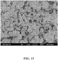
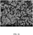
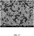
- SEM micrographs will show the change in morphology of the phosphor crystals as the amount of Ca is increased beyond the amount used to charge balance the substitution of Si by Al.
- Sample 1 is a well-known 2-5-8 red-emitting nitride phosphor used herein as a control; it has the composition Sr 1.95 Si 5 N 8 Eu 0.05 .
- Samples 2 through 5 are based on the composition of Sample 1, but with increasing amounts of calcium added as modifier cations; in these samples the modifier cations do not have a charge compensation role to play, for Si substitution at least. These samples have a composition represented by the formula Ca x Sr 1.95 Si 5 N 8 Eu 0.05 .
- Samples 6 through 8 are based on the composition of Sample 1, but with calcium substituting for strontium in increasing amounts; in these samples the modifier cations do not have a charge compensation role to play. These samples have a composition represented by the formula Ca x Sr 1.95-x Si 5 N 8 Eu 0.05 . These Samples are compared with Samples 2 through 4 which have the same amount of calcium added, but in Samples 2 through 4 the calcium does not substitute for strontium -it is in addition to the strontium and is expected to be present in the phosphor crystal in interstitial lattice positions.
- Samples 9 through 12 are based on the composition of Sample 1, but with (1) some aluminum substituted for silicon, and (2) with increasing amounts of calcium added as modifier cations, where the calcium is BOTH playing the role of charge compensation for the substitution of aluminum for silicon, and is present in amounts beyond what is needed for charge compensation and may result in improved phosphor stability under conditions of heat and humidity.
- These samples have a composition represented by the formula Ca x Sr 1.95 Si 4.9 Al 0.1 N 8 Eu 0.05 .
- Samples 13 through 15 are similar to Samples 9 through 12, except for the amount of aluminum being slightly greater in Samples 13 through 15. These samples have a composition represented by the formula Ca x Sr 1.95 Si 4.88 Al 0.12 N 8 Eu 0.05 . Furthermore, Sample 13 has only enough additional calcium to charge compensate the substitution of aluminum for silicon, whereas Samples 14 and 15 have amounts of calcium beyond what is needed for charge compensation.
- the phosphors under blue excitation, may be configured to emit light having a peak emission wavelength greater than about 620 nm, in embodiments greater than 623 nm, and in further embodiments greater than about 626 nm, where blue may be defined as light having a wavelength ranging from about 420 nm to about 470 nm.
- the present phosphors may also be excited by radiation having shorter wavelengths; e.g., from about 200 nm to about 420 nm, but when the excitation radiation is in the x-ray or UV, a separate blue-emitting phosphor is provided to contribute a blue component to the desired white light for a white light source.
- the present phosphors may also be excited by radiation having longer wavelengths, wherein the wavelength ranges from about 200 nm to about 480 nm.
- a common blue excitation source is an InGaN LED, or GaN LED, emitting with a peak at about 460 nm.
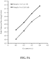
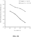
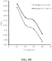
- FIGS. 5A-5D show trends based on the phosphor calcium content of the peak emission wavelength, peak photoluminescence intensity (PL) and CIE x and y chromaticity coordinates, for red-emitting nitride-based calcium-stabilized phosphors Samples 2 through 5 (no aluminum) and 9 through 12 (aluminum containing), according to some embodiments of the present invention. All of these phosphors have excess calcium, beyond what is required for charge balance in the case of the aluminum-containing samples; and all of these phosphors are assumed to have the calcium present in the crystal structure at interstitial sites. The trends for the no aluminum and the aluminum-containing samples are very similar, suggesting that the trends may be dominated by the interstitial calcium content.
- PL peak photoluminescence intensity
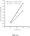
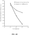
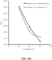
- FIGS. 6A-6D show trends with phosphor calcium content of the peak emission wavelength, peak photoluminescence intensity (PL) and CIE x and y chromaticity coordinates, for red-emitting nitride-based calcium-stabilized phosphors Samples 2 through 4 (additional calcium) and 6 through 8 (substitutional calcium), according to some embodiments of the present invention. There is an appreciable difference in the trends between the additional (assumed interstitial) calcium and the substitutional calcium, suggesting the location of the calcium within the crystal lattice may be significant.
- the ENERGY STAR ® "Program Requirements for Integral LED Lamps" requires that for all LED lamps "the change of chromaticity over the minimum lumen maintenance test period (6000 hours) shall be within 0.007 on the CIE 1976 (u',v') diagram” and depending on lamp type, the lamp must have " ⁇ 70% lumen maintenance (L70) at 15,000 or 25,000 hours of operation”.
- the ENERGY STAR ® requirements are for the lamp performance and include all components of the lamp such as the LEDs, phosphor, electronic driver circuitry, optics and mechanical components. In principal, the degradation in brightness of a white LED with aging can be due not only to the phosphor, but also to the blue LED chip.
- CIE ⁇ x, CIE ⁇ y change in chromaticity
- the accelerated testing is done on phosphor coated 3000K white LEDs prepared as follows: phosphor particles are combined with a binder, such as epoxy or silicone, and then applied to the LED chip. The coated LED is placed in an oven at the specified temperature and humidity and operated continuously for the testing period.
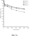
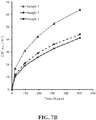
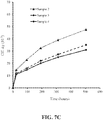
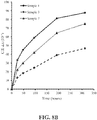
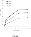
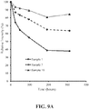
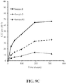
- FIGS. 7A-7C , 8A-8C , 9A-9C and 10A-10C show the results of reliability testing under the conditions of 85°C and 85% relative humidity of phosphor Samples 2 through 4, Samples 1, 3 and 7, Samples 1, 3 and 10 and Samples 13 through 15, respectively.
- the figures show the change in photoluminescent intensity (brightness) with time, the change in CIE x chromaticity coordinate with time, and the change in CIE y chromaticity coordinate with time.
- the Sr 2 Si 5 N 8 :Eu control sample (Sample 1) showed results that would typically be unacceptable to the industry - all other Samples showed different levels of improvement over the control, the best performance being shown by Samples 10 and 15 which will most likely satisfy the typical industry heat and humidity stability requirement.
- FIGS. 7A-7C show an improvement in reliability with increase in additional calcium content of the no aluminum-content phosphors.
- FIGS. 8A-8C compare the control with a substitutional calcium phosphor and an additional calcium phosphor - all phosphors without aluminum and where the two calcium-containing phosphors differ in composition only in that Sample 3 has more strontium than Sample 7, since in Sample 7 the calcium has substituted for strontium; the best reliability is seen for the phosphor with additional calcium.
- FIGS. 9A-9C compare the control with an additional calcium phosphor without aluminum and an additional calcium phosphor with aluminum - the two calcium-containing phosphors differ in composition only in that Sample 10 contains aluminum and Sample 3 does not; the best reliability is seen for the phosphor containing aluminum.
- FIGS. 10A-10C show an improvement in reliability for the additional calcium phosphors with increase in calcium content.
- the most significant improvement in stability over the control (Sample 1), as defined by maintaining intensity and chromaticity, is realized by Ca interstitial charge balancing and Al substituting for Si, plus excess interstitial Ca (beyond what is required for charge balance of the Al); the best stability results are seen for the higher Ca/Al ratio materials, as exemplified by Samples 10 and 15 (see Tables 3B and 4B).
- Samples 10 and 15 are uncoated phosphors, and yet shows excellent stability - stability data is shown for up to 800 hours for Sample 15 and it is expected that after 1000 hours Sample 15 will meet the accelerated testing criteria used to establish ENERGY STAR ® compliance. Even though Samples 10 and 15 show excellent stability without coating, Samples 10 and 15 can be coated to provide expected further stability improvement. Similarly, other Samples can be coated to improve stability.
- the particles of the phosphor with the composition of the Samples of the present invention can be coated with one or more coatings of, for example, SiO 2 , Al 2 O 3 and/or TiO 2 , as taught in U.S. Patent US 9,006,966 for COATINGS FOR PHOTOLUMINESCENT MATERIALS and U.S. Appl. Publication No. 2013092964 for HIGHLY RELIABLE PHOTOLUMINESCENT MATERIALS HAVING A THICK AND UNIFORM TITANIUM DIOXIDE COATING.
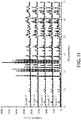
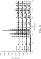
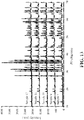
- FIGS. 11-14 show XRD patterns of red-emitting nitride-based phosphors of the present invention; the XRD pattern for Sample 1 is shown for comparison.
- FIGS. 15-17 show secondary electron micrographs of as prepared red-emitting nitride-based calcium-stabilized phosphors Sample 3 ( FIG. 16 ) (additional calcium) and Sample 7 ( FIG. 17 ) (substitutional calcium), according to some embodiments of the present invention, and prior art red-emitting nitride-based 2-5-8 phosphor Sample 1 ( FIG. 15 ) is shown for comparison. All of FIGS. 15-17 show some particles with a higher aspect ratio (length to width) - in excess of 3. Furthermore, a comparison of FIGS. 15-17 suggests that the percentage of high aspect ratio particles is greater for the control ( FIG. 15 ) than for the samples of the phosphors of the present invention.
- the starting materials included at least one of the compounds Si 3 N 4 , AlN, Ca 3 N 2 , Sr 3 N 2 , BN, GaN, SiO 2 , Al 2 O 3 , and EuCl 3 .
- the furnace was evacuated to 10 -2 Pa, and the sample heated to 150°C under these vacuum conditions.
- a high purity N 2 gas was introduced into the chamber; the temperature of the furnace was then increased to about 1700°C at a substantially constant heating rate of 4°C/min.
- the samples were maintained at 1700°C for about 7 hours.
- a flux such as ammonium chloride, may also be used in the fabrication of the phosphors of the present invention.
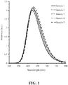
- FIG. 1 is the emission spectra of the phosphors from Samples 1 through 5. Powder x-ray diffraction measurements using the K ⁇ line of a Cu target are shown in FIG. 11 for the phosphors of Samples 1 through 5.
- Table 1A Composition of starting raw materials for Samples 1 through 5 Compound EuCl 3 Sr 3 N 2 Ca 3 N 2 Si 3 N 4 AlN Sample 1 5.166 75.62 0 93.52 0 Sample 2 2.583 37.81 0.988 46.76 0 Sample 3 2.583 37.81 1.976 46.76 0 Sample 4 2.583 37.81 2.964 46.76 0 Sample 5 2.583 37.81 3.952 46.76 0
- Table 1B Emission Peak wavelength, Intensity and CIE of Samples 1 through 5 with Composition Ca x Sr 1.95 Si 5 N 8 Eu 0.05 Test Results Compound Ca Content, x Al Content Emission Peak Wavelength (nm) PL Intensity (a.u.) CIE (x) CIE (y
- the emission spectra of phosphor Samples 6 through 8 are shown in FIG. 2 .
- X-ray diffraction measurements using the K ⁇ line of a Cu target were obtained, and the XRD patterns of Samples 6 through 8 are shown in FIG 12 .
- Table 2A Composition of starting raw materials for Samples 6 through 8 Compound EuCl 3 Sr 3 N 2 Ca 3 N 2 Si 3 N 4 AlN Sample 6 2.583 35.87 0.988 46.76 0 Sample 7 2.583 33.93 1.976 46.76 0 Sample 8 2.583 31.99 2.964 46.76 0
- Table 2B Emission Peak wavelength, Intensity and CIE of Samples 6 through 8 with Composition Ca x Sr 1.95-x Si 5-y Al y N 8 Eu 0.05 Test Results Compound Ca Content, x Al Content Emission Peak Wavelength (nm) PL Intensity (a.u.) CIE (x) CIE (y) Sample 6 0.1 0 624.54 1.66 0.6443 0.355 Sample 7 0.2 0 627.86 1.57 0.6476 0.352 Sample 8 0.3 0 631.08 1.51 0.6500 0.350
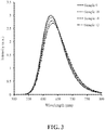
- FIG. 3 is the emission spectra of the phosphors from Samples 9 through 12. x-ray diffraction measurements using the K ⁇ line of a Cu target were obtained, and the XRD patterns of Samples 9 through 12 are shown in FIG. 13 .
- Table 3A Composition of starting raw materials for Samples 9 through 12 Compound EuCl 3 Sr 3 N 2 Ca 3 N 2 Si 3 N 4 AlN Sample 9 2.583 37.81 0.988 45.83 0.82 Sample 10 2.583 37.81 1.976 45.83 0.82 Sample 11 2.583 37.81 2.964 45.83 0.82 Sample 12 2.583 37.81 3.952 45.83 0.82 Table 3B Emission Peak wavelength, Intensity and CIE of Samples 9 through 12 with Composition Ca x Sr 1.95 Si 4.9 Al 0.1 N 8 Eu 0.05 Test Results Compound Ca Content, x Al Content, y Emission Peak Wavelength (nm) PL Intensity (a.u.) CIE (x) CIE (y) Sample 9 0.1 0.1 626.50 1.56 0.6442 0.3554 Sample 10 0.2 0.1 628.42 1.52 0.6470 0.3526 Sample 11 0.3 0.1 630.75 1.46 0.6476 0.3520 Sample 12 0.4 0.1 632.71 1.41 0.6504 0.
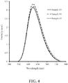
- FIG. 4 is the emission spectra of the phosphors from Samples 13 through 15. X-ray diffraction measurements using the K ⁇ line of a Cu target were obtained, and the XRD patterns of Samples 13 through 15 are shown in FIG. 14 .
- Table 4A Composition of starting raw materials for Samples 13 through 15 Compound EuCl 3 Sr 3 N 2 Ca 3 N 2 Si 3 N 4 AlN Sample 13 5.166 75.622 1.186 91.28 1.968 Sample 14 5.166 75.622 1.976 91.28 1.968 Sample 15 5.166 75.622 3.592 91.28 1.968 Table 4B Emission Peak wavelength, Intensity and CIE of Samples 13 through 15 with Composition Ca x Sr 1.95 Si 4.88 Al 0.12 N 8 Eu 0.05 Test Results Compound Ca Content, x Al Content, y Emission Peak Wavelength (nm) PL Intensity (a.u.) CIE (x) CIE (y) Sample 13 0.06 (charge balanced) 0.12 625 1.66 0.6450 0.3540 Sample 14 0.1 (Ca excess) 0.12 626 1.59 0.6459 0.3538 Sample 15 0.2 (Ca excess) 0.12 629 1.52 0.6478 0.3518
- phosphor compositions may be a red-emitting phosphor comprising a nitride-based composition represented by the chemical formula M a Sr b Si c Al d N e Eu f , wherein: M is Ca, and 0 ⁇ a ⁇ 1.0; 1.5 ⁇ b ⁇ 2.5; 4.0 ⁇ c ⁇ 5.0;0 ⁇ d ⁇ 1.0; 7.5 ⁇ e ⁇ 8.5; and 0 ⁇ f ⁇ 0.1;wherein a+b+f>2+d/v and v is the valence of M.
- M is Ca, and 0 ⁇ a ⁇ 1.0; 1.5 ⁇ b ⁇ 2.5; 4.0 ⁇ c ⁇ 5.0;0 ⁇ d ⁇ 1.0; 7.5 ⁇ e ⁇ 8.5; and 0 ⁇ f ⁇ 0.1;wherein a+b+f>2+d/v and v is the valence of M.
- phosphor compositions that may be made which are represented by the chemical formula M x M' 2 Si 5-y Al y N 8 :A, wherein: M is Mg, Ca, Sr, Ba, Y, Li, Na, K and Zn, and x>0; M' is at least one of Mg, Ca, Sr, Ba, and Zn; 0 ⁇ y ⁇ 0.15; and A is at least one of Eu, Ce, Tb, Pr, and Mn; wherein x>y/v and v is the valence of M, and wherein the phosphors have the general crystalline structure of M' 2 Si 5 N 8 :A.
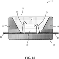
- FIG. 18 illustrates a light emitting device, according to some embodiments.
- the device 10 can comprise a blue light emitting, within the range of 450 nm to 470 nm, GaN (gallium nitride) LED chip 12, for example, housed within a package.
- the package which can for example comprise a low temperature co-fired ceramic (LTCC) or high temperature polymer, comprises upper and lower body parts 16 , 18.
- the upper body part 16 defines a recess 20 , often circular in shape, which is configured to receive the LED chips 12.
- the package further comprises electrical connectors 22 and 24 that also define corresponding electrode contact pads 26 and 28 on the floor of the recess 20.
- LTCC low temperature co-fired ceramic
- the LED chip 12 can be mounted to a thermally conductive pad located on the floor of the recess 20.
- the LED chip's electrode pads are electrically connected to corresponding electrode contact pads 26 and 28 on the floor of the package using bond wires 30 and 32 and the recess 20 is completely filled with a transparent polymer material 34 , typically a silicone, which is loaded with a mixture of a yellow and/or green phosphor and a red phosphor material of the present invention such that the exposed surfaces of the LED chip 12 are covered by the phosphor/polymer material mixture.
- a transparent polymer material 34 typically a silicone
- the walls of the recess are inclined and have a light reflective surface.
- FIGS. 19A and 19B illustrate a solid-state light emitting device, according to some embodiments.
- the device 100 is configured to generate warm white light with a CCT (Correlated Color Temperature) of approximately 3000K and a luminous flux of approximately 1000 lumens and can be used as a part of a downlight or other lighting fixture.
- the device 100 comprises a hollow cylindrical body 102 composed of a circular disc-shaped base 104 , a hollow cylindrical wall portion 106 and a detachable annular top 108.
- the base 104 is preferably fabricated from aluminum, an alloy of aluminum or any material with a high thermal conductivity.
- the base 104 can be attached to the wall portion 106 by screws or bolts or by other fasteners or by means of an adhesive.
- the device 100 further comprises a plurality (four in the example illustrated) of blue light emitting LEDs 112 (blue LEDs) that are mounted in thermal communication with a circular-shaped MCPCB (metal core printed circuit board) 114.
- the blue LEDs 112 can comprise a ceramic packaged array of twelve 0.4W GaN-based (gallium nitride-based) blue LED chips that are configured as a rectangular array 3 rows by 4 columns.
- the device 100 can further comprise light reflective surfaces 116 and 118 that respectively cover the face of the MCPCB 114 and the inner curved surface of the top 108.
- the device 100 further comprises a photoluminescent wavelength conversion component 120 that is operable to absorb a proportion of the blue light generated by the LEDs 112 and convert it to light of a different wavelength by a process of photoluminescence.
- the emission product of the device 100 comprises the combined light generated by the LEDs 112 and the photoluminescent wavelength conversion component 120.
- the wavelength conversion component is positioned remotely to the LEDs 112 and is spatially separated from the LEDs. In this patent specification "remotely" and “remote” means in a spaced or separated relationship.
- the wavelength conversion component 120 is configured to completely cover the housing opening such that all light emitted by the lamp passes through the component 120. As shown the wavelength conversion component 120 can be detachably mounted to the top of the wall portion 106 using the top 108 enabling the component and emission color of the lamp to be readily changed.
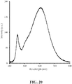
- FIG. 20 shows the emission spectrum from a white light emitting device, such as described above with reference to FIGS. 18 , 19A and 19B , comprising a blue-emitting InGaN LED, a red phosphor having the composition of Sample 14, and one or more yellow/green phosphors with peak emission within the range of 500 nm to 580 nm, such as a phosphor described in U.S. Patent US 8,529,791 and U.S. Patent US 8,475,683 .
- the yellow/green phosphor may be a silicate.
- the white LED may further comprise another phosphor as may be needed to achieve a desired emission spectrum, for example an orange aluminate.
Landscapes
- Chemical & Material Sciences (AREA)
- Inorganic Chemistry (AREA)
- Engineering & Computer Science (AREA)
- Materials Engineering (AREA)
- Organic Chemistry (AREA)
- Luminescent Compositions (AREA)
- Led Device Packages (AREA)
Claims (12)
- Rot emittierender Leuchtstoff, umfassend eine Nitrid-basierte Zusammensetzung, die durch die chemische Formel MaSrbSicAldNeEuf dargestellt ist, wobei:M Ca ist, und 0 < a < 1.0;1.5 < b < 2.5;4.0 ≤ c ≤ 5.0;0 < d ≤ 1.0;7.5 < e < 8.5; und0 < f < 0.1;wobei a+b+f >2+d/v und v die Valenz von M ist.
- Weißlicht emittierende Vorrichtung, umfassend:eine Festkörper-Anregungsquelle mit Emissionswellenlänge in einem Bereich von 200 nm bis 480 nm;einen rot emittierenden Leuchtstoff nach Anspruch 1, wobei der rot emittierende Leuchtstoff konfiguriert ist, um Anregungsstrahlung von der Anregungsquelle zu absorbieren und Licht mit einer Emissions-Peakwellenlänge im Bereich von 620 nm bis 650 nm zu emittieren; undeinen gelb/grün emittierenden Leuchtstoff mit einer Peakemissionswellenlänge im Bereich von 500 nm bis 580 nm.
- Rot emittierender Leuchtstoff oder Weißlicht emittierende Vorrichtung nach Ansprüchen 1 oder Anspruch 2, weiterhin umfassend mindestens eines von F, Cl, Br und O.
- Rot emittierender Leuchtstoff oder Weißlicht emittierende Vorrichtung nach einem der Ansprüche 1 bis 3, wobei der rot emittierende Leuchtstoff ausgewählt ist aus der Gruppe, bestehend aus:Eu0.05Ca0.1Sr1.95Si4.9Al0.1N8;Eu0.05Ca0.2Sr1.95Si4.9Al0.1N8;Eu0.05Ca0.3Sr1.95Si4.9Al0.1N8;Eu0.05Ca0.4Sr1.95Si4.9Al0.1N8;Eu0.05Ca0.1Sr1.95Si4.88Al0.12N8; undEu0.05Ca0.2Sr1.95Si4.88Al0.12N8.
- Rot emittierender Leuchtstoff nach Anspruch 4, wobei der rot emittierende Leuchtstoff so konfiguriert ist, dass unter Anregung durch eine blaue LED die Reduktion in der Photolumineszenz-Intensität nach 800 Stunden Alterung bei 85 °C und 85 % Luftfeuchtigkeit nicht größer ist als 15 %.
- Rot emittierender Leuchtstoff nach Anspruch 4, wobei der rot emittierende Leuchtstoff so konfiguriert ist, dass die Abweichung in den Chromatizitätskoordinaten CIE Δx und CIE Δy nach 800 Stunden Alterung bei 85 °C und 85 % relativer Luftfeuchtigkeit für jede Koordinate kleiner oder gleich 0.015 ist.
- Rot emittierender Leuchtstoff nach Anspruch 4, wobei die Abweichung in den Chromatizitätskoordinaten CIE Δx und CIE Δy für jede Koordinate kleiner oder gleich 0.005 ist.
- Rot emittierender Leuchtstoff nach Anspruch 4, wobei der rot emittierende Leuchtstoff Strahlung bei einer Wellenlänge im Bereich von 200 nm bis 550 nm absorbiert und Licht mit einer Photolumineszenz-Peakemissionswellenlänge von größer als 620.0 nm emittiert.
- Rot emittierender Leuchtstoff oder Weißlicht emittierende Vorrichtung nach Anspruch 1 oder Anspruch 2, wobei der rot emittierende Leuchtstoff aus Ca, Sr, Si, Al, N, Eu und mindestens einem von F, Cl, Br und O besteht.
- Rot emittierender Leuchtstoff nach Anspruch 1, wobei der rot emittierende Leuchtstoff die allgemeine kristalline Struktur Sr2Si5N8: Eu aufweist, und wobei Al Si in der allgemeinen kristallinen Struktur ersetzt und M in der allgemeinen kristallinen Struktur auf Zwischengitterplätzen angeordnet ist.
- Weißlicht emittierende Vorrichtung nach Anspruch 2, wobei der rot emittierende Leuchtstoff die Formel Eu0.05Ca0.1Sr1.95Si4.88Al0.12N8 aufweist.
- Weißlicht emittierende Vorrichtung nach Anspruch 2, wobei die Anregungsquelle eine Emissionswellenlänge in einem Bereich von 450 nm bis 470 nm aufweist.
Priority Applications (1)
| Application Number | Priority Date | Filing Date | Title |
|---|---|---|---|
| EP16175596.2A EP3153563A1 (de) | 2012-07-18 | 2013-07-17 | Rot emittierende nitrid-basierte phosphore |
Applications Claiming Priority (4)
| Application Number | Priority Date | Filing Date | Title |
|---|---|---|---|
| US201261673191P | 2012-07-18 | 2012-07-18 | |
| US13/871,961 US8663502B2 (en) | 2011-12-30 | 2013-04-26 | Red-emitting nitride-based phosphors |
| US13/922,231 US8597545B1 (en) | 2012-07-18 | 2013-06-19 | Red-emitting nitride-based calcium-stabilized phosphors |
| PCT/US2013/050789 WO2014014975A1 (en) | 2012-07-18 | 2013-07-17 | Red-emitting nitride-based calcium-stabilized phosphors |
Related Child Applications (2)
| Application Number | Title | Priority Date | Filing Date |
|---|---|---|---|
| EP16175596.2A Division-Into EP3153563A1 (de) | 2012-07-18 | 2013-07-17 | Rot emittierende nitrid-basierte phosphore |
| EP16175596.2A Division EP3153563A1 (de) | 2012-07-18 | 2013-07-17 | Rot emittierende nitrid-basierte phosphore |
Publications (3)
| Publication Number | Publication Date |
|---|---|
| EP2732007A1 EP2732007A1 (de) | 2014-05-21 |
| EP2732007A4 EP2732007A4 (de) | 2015-01-21 |
| EP2732007B1 true EP2732007B1 (de) | 2017-05-31 |
Family
ID=49640688
Family Applications (2)
| Application Number | Title | Priority Date | Filing Date |
|---|---|---|---|
| EP13802521.8A Not-in-force EP2732007B1 (de) | 2012-07-18 | 2013-07-17 | Rotemittierende calcium-stabilisierte phosphore auf nitridbasis |
| EP16175596.2A Withdrawn EP3153563A1 (de) | 2012-07-18 | 2013-07-17 | Rot emittierende nitrid-basierte phosphore |
Family Applications After (1)
| Application Number | Title | Priority Date | Filing Date |
|---|---|---|---|
| EP16175596.2A Withdrawn EP3153563A1 (de) | 2012-07-18 | 2013-07-17 | Rot emittierende nitrid-basierte phosphore |
Country Status (7)
| Country | Link |
|---|---|
| US (3) | US8597545B1 (de) |
| EP (2) | EP2732007B1 (de) |
| JP (2) | JP5735179B2 (de) |
| KR (1) | KR101424236B1 (de) |
| CN (2) | CN105154079B (de) |
| TW (2) | TWI450945B (de) |
| WO (1) | WO2014014975A1 (de) |
Families Citing this family (38)
| Publication number | Priority date | Publication date | Assignee | Title |
|---|---|---|---|---|
| US8740400B2 (en) | 2008-03-07 | 2014-06-03 | Intematix Corporation | White light illumination system with narrow band green phosphor and multiple-wavelength excitation |
| US20120138874A1 (en) | 2010-12-02 | 2012-06-07 | Intematix Corporation | Solid-state light emitting devices and signage with photoluminescence wavelength conversion and photoluminescent compositions therefor |
| US8663502B2 (en) * | 2011-12-30 | 2014-03-04 | Intematix Corporation | Red-emitting nitride-based phosphors |
| EP2797838A4 (de) | 2011-12-30 | 2015-07-01 | Intematix Corp | Nitridphosphore mit interstitiellen kationen für ladungsausgleich |
| US8597545B1 (en) * | 2012-07-18 | 2013-12-03 | Intematix Corporation | Red-emitting nitride-based calcium-stabilized phosphors |
| US9219202B2 (en) * | 2013-04-19 | 2015-12-22 | Cree, Inc. | Semiconductor light emitting devices including red phosphors that exhibit good color rendering properties and related red phosphors |
| US9753357B2 (en) | 2014-02-27 | 2017-09-05 | Intematix Corporation | Compact solid-state camera flash |
| US9318670B2 (en) * | 2014-05-21 | 2016-04-19 | Intematix Corporation | Materials for photoluminescence wavelength converted solid-state light emitting devices and arrangements |
| CN105985772B (zh) * | 2015-02-11 | 2019-08-30 | 大连利德照明研发中心有限公司 | 固体光源用荧光材料、其制造方法及包含该荧光材料的组合物 |
| CN107532082A (zh) * | 2015-04-27 | 2018-01-02 | 默克专利有限公司 | 无机发光材料和无机发光材料转化led |
| US10066160B2 (en) | 2015-05-01 | 2018-09-04 | Intematix Corporation | Solid-state white light generating lighting arrangements including photoluminescence wavelength conversion components |
| KR102477353B1 (ko) | 2015-08-06 | 2022-12-16 | 삼성전자주식회사 | 적색 형광체, 백색 발광장치 및 조명 장치 |
| JP6602111B2 (ja) * | 2015-08-28 | 2019-11-06 | 三星電子株式会社 | 半導体発光装置 |
| EP3347924A4 (de) | 2015-09-10 | 2019-04-10 | Intematix Corporation | Phosphorkonvertierte weisslichtemittierende vorrichtungen und photolumineszenzverbindungen für allgemeine beleuchtung und hintergrundbeleuchtung von anzeigen |
| US10847566B2 (en) | 2018-05-04 | 2020-11-24 | Intematix Corporation | High color rendering white light emitting devices and high color rendering photoluminescence compositions |
| JP6611036B2 (ja) * | 2015-09-10 | 2019-11-27 | パナソニックIpマネジメント株式会社 | 発光装置及び照明用光源 |
| KR102659032B1 (ko) * | 2016-02-23 | 2024-04-22 | 루미리즈 홀딩 비.브이. | 발광 디바이스용 파장 변환 재료 |
| WO2018005440A1 (en) | 2016-06-29 | 2018-01-04 | Sabic Global Technologies B.V. | Method to improve remote phosphor optical properties in polycarbonate |
| DE102017122996A1 (de) | 2017-10-04 | 2019-04-04 | Osram Opto Semiconductors Gmbh | Leuchtstoffmischung, Konversionselement und optoelektronisches Bauelement |
| WO2019118959A1 (en) | 2017-12-17 | 2019-06-20 | Intematix Corporation | Dimmable solid-state light emitting devices |
| CN108317768A (zh) * | 2017-12-29 | 2018-07-24 | 中国海洋石油集团有限公司 | 井下光谱仪的主动制冷系统 |
| DE102018101428A1 (de) * | 2018-01-23 | 2019-07-25 | Osram Opto Semiconductors Gmbh | Optoelektronisches Bauelement |
| CN108165266B (zh) * | 2018-03-23 | 2019-01-08 | 旭宇光电(深圳)股份有限公司 | 一种氟氮化物荧光粉及包含该荧光粉的发光器件 |
| US10371325B1 (en) | 2018-06-25 | 2019-08-06 | Intematix Corporation | Full spectrum white light emitting devices |
| US10685941B1 (en) | 2019-07-09 | 2020-06-16 | Intematix Corporation | Full spectrum white light emitting devices |
| KR102158811B1 (ko) * | 2018-07-03 | 2020-09-22 | 주식회사 엘엠에스 | 지문인식센서용 광학원판 및 이를 포함하는 광학필터 |
| CN109370587B (zh) * | 2018-09-06 | 2019-10-29 | 旭宇光电(深圳)股份有限公司 | 氮化物近红外荧光材料、含有氮化物近红外荧光材料的发光装置 |
| JP7319508B2 (ja) * | 2018-11-30 | 2023-08-02 | 日亜化学工業株式会社 | セラミックス焼結体の製造方法、セラミックス焼結体及び発光装置 |
| US11342311B2 (en) | 2019-03-18 | 2022-05-24 | Intematix Corporation | LED-filaments and LED-filament lamps utilizing manganese-activated fluoride red photoluminescence material |
| JP7242894B2 (ja) | 2019-03-18 | 2023-03-20 | インテマティックス・コーポレーション | 光ルミネセンス層状構造体を備えるパッケージ化された白色発光デバイス |
| EP3942607A1 (de) | 2019-03-18 | 2022-01-26 | Intematix Corporation | Led-filament |
| WO2020190960A1 (en) | 2019-03-18 | 2020-09-24 | Intematix Corporation | Led-filament |
| US11781714B2 (en) | 2019-03-18 | 2023-10-10 | Bridgelux, Inc. | LED-filaments and LED-filament lamps |
| US10887960B2 (en) * | 2019-03-28 | 2021-01-05 | Lumileds Llc | Color tunable light emitting diode (LED) systems, LED lighting systems, and methods |
| WO2021007123A1 (en) | 2019-07-09 | 2021-01-14 | Intematix Corporation | Full spectrum white light emitting devices |
| CA3145214A1 (en) | 2019-07-23 | 2021-01-28 | Jakoah Brgoch | Narrow green-emitting phosphors |
| EP4049319B1 (de) | 2019-10-23 | 2025-11-19 | Intematix Corporation | Weisslichtemittierende vorrichtungen mit hohem farbraum und umgewandelter fotolumineszenzwellenlänge |
| EP4411842A1 (de) | 2023-02-06 | 2024-08-07 | Bridgelux, Inc. | Vollspektrum-weisslicht-emittierende geräte |
Family Cites Families (96)
| Publication number | Priority date | Publication date | Assignee | Title |
|---|---|---|---|---|
| US3207583A (en) | 1963-03-28 | 1965-09-21 | American Agricultural Chem Co | Preparation of technical grade red phosphorus |
| EP1104799A1 (de) | 1999-11-30 | 2001-06-06 | Patent-Treuhand-Gesellschaft für elektrische Glühlampen mbH | Rotstrahlendes lumineszentes Material |
| DE10133352A1 (de) | 2001-07-16 | 2003-02-06 | Patent Treuhand Ges Fuer Elektrische Gluehlampen Mbh | Beleuchtungseinheit mit mindestens einer LED als Lichtquelle |
| DE10147040A1 (de) | 2001-09-25 | 2003-04-24 | Patent Treuhand Ges Fuer Elektrische Gluehlampen Mbh | Beleuchtungseinheit mit mindestens einer LED als Lichtquelle |
| SG173925A1 (en) | 2002-03-22 | 2011-09-29 | Nichia Corp | Nitride phosphor and production process thereof, and light emitting device |
| JP4244653B2 (ja) | 2003-02-17 | 2009-03-25 | 日亜化学工業株式会社 | シリコンナイトライド系蛍光体及びそれを用いた発光装置 |
| US7026755B2 (en) | 2003-08-07 | 2006-04-11 | General Electric Company | Deep red phosphor for general illumination applications |
| US7252787B2 (en) | 2003-10-29 | 2007-08-07 | General Electric Company | Garnet phosphor materials having enhanced spectral characteristics |
| TWI359187B (en) | 2003-11-19 | 2012-03-01 | Panasonic Corp | Method for preparing nitridosilicate-based compoun |
| JP3837588B2 (ja) * | 2003-11-26 | 2006-10-25 | 独立行政法人物質・材料研究機構 | 蛍光体と蛍光体を用いた発光器具 |
| JP4165412B2 (ja) | 2004-02-13 | 2008-10-15 | 昭栄化学工業株式会社 | 窒化物蛍光体、窒化物蛍光体の製造方法、白色発光素子及び顔料 |
| JP4511849B2 (ja) | 2004-02-27 | 2010-07-28 | Dowaエレクトロニクス株式会社 | 蛍光体およびその製造方法、光源、並びにled |
| TWI262609B (en) | 2004-02-27 | 2006-09-21 | Dowa Mining Co | Phosphor and manufacturing method thereof, and light source, LED using said phosphor |
| US7229573B2 (en) | 2004-04-20 | 2007-06-12 | Gelcore, Llc | Ce3+ and Eu2+ doped phosphors for light generation |
| KR100900372B1 (ko) | 2004-04-27 | 2009-06-02 | 파나소닉 주식회사 | 형광체 조성물과 그 제조 방법, 및 그 형광체 조성물을이용한 발광 장치 |
| US6956247B1 (en) | 2004-05-26 | 2005-10-18 | Lumileds Lighting U.S., Llc | Semiconductor light emitting device including photonic band gap material and luminescent material |
| JP2008501818A (ja) | 2004-05-27 | 2008-01-24 | コーニンクレッカ フィリップス エレクトロニクス エヌ ヴィ | 放射源及び蛍光材料を有する照明装置 |
| JP4414821B2 (ja) | 2004-06-25 | 2010-02-10 | Dowaエレクトロニクス株式会社 | 蛍光体並びに光源およびled |
| JP4565141B2 (ja) | 2004-06-30 | 2010-10-20 | 独立行政法人物質・材料研究機構 | 蛍光体と発光器具 |
| JP4645089B2 (ja) | 2004-07-26 | 2011-03-09 | 日亜化学工業株式会社 | 発光装置および蛍光体 |
| JP4422653B2 (ja) | 2004-07-28 | 2010-02-24 | Dowaエレクトロニクス株式会社 | 蛍光体およびその製造方法、並びに光源 |
| US7138756B2 (en) | 2004-08-02 | 2006-11-21 | Dowa Mining Co., Ltd. | Phosphor for electron beam excitation and color display device using the same |
| US7311858B2 (en) | 2004-08-04 | 2007-12-25 | Intematix Corporation | Silicate-based yellow-green phosphors |
| US8017035B2 (en) | 2004-08-04 | 2011-09-13 | Intematix Corporation | Silicate-based yellow-green phosphors |
| US7575697B2 (en) | 2004-08-04 | 2009-08-18 | Intematix Corporation | Silicate-based green phosphors |
| US7390437B2 (en) | 2004-08-04 | 2008-06-24 | Intematix Corporation | Aluminate-based blue phosphors |
| JP4543250B2 (ja) | 2004-08-27 | 2010-09-15 | Dowaエレクトロニクス株式会社 | 蛍光体混合物および発光装置 |
| US7476338B2 (en) | 2004-08-27 | 2009-01-13 | Dowa Electronics Materials Co., Ltd. | Phosphor and manufacturing method for the same, and light source |
| JP4543251B2 (ja) | 2004-08-31 | 2010-09-15 | Dowaエレクトロニクス株式会社 | 蛍光体及び光源 |
| WO2006033418A1 (ja) | 2004-09-22 | 2006-03-30 | National Institute For Materials Science | 蛍光体とその製造方法および発光器具 |
| JP4674348B2 (ja) * | 2004-09-22 | 2011-04-20 | 独立行政法人物質・材料研究機構 | 蛍光体とその製造方法および発光器具 |
| CN101031630B (zh) | 2004-10-15 | 2010-10-13 | 三菱化学株式会社 | 荧光体和使用该荧光体的发光装置、以及图像显示装置和照明装置 |
| US7671529B2 (en) * | 2004-12-10 | 2010-03-02 | Philips Lumileds Lighting Company, Llc | Phosphor converted light emitting device |
| EP1837386B1 (de) | 2004-12-28 | 2016-11-23 | Nichia Corporation | Nitridphosphor, verfahren zu seiner herstellung und seine verwendung in lichtemittierender vorrichtung |
| JP2006213910A (ja) | 2005-01-06 | 2006-08-17 | Matsushita Electric Ind Co Ltd | 酸窒化物蛍光体及び発光装置 |
| CN101103088A (zh) * | 2005-01-10 | 2008-01-09 | 皇家飞利浦电子股份有限公司 | 包含陶瓷发光转换器的照明系统 |
| JP4756261B2 (ja) | 2005-01-27 | 2011-08-24 | 独立行政法人物質・材料研究機構 | 蛍光体とその製造方法および発光器具 |
| EP1845146B1 (de) | 2005-01-31 | 2015-03-04 | Ube Industries, Ltd. | Rot emittierender nitrid-leuchtstoff und herstellungsverfahren dafür |
| US7537698B2 (en) | 2005-02-28 | 2009-05-26 | Hitachi Plant Technologies, Ltd. | Process and equipment for treating ammonium containing liquid |
| CN101138278A (zh) | 2005-03-09 | 2008-03-05 | 皇家飞利浦电子股份有限公司 | 包括辐射源和荧光材料的照明系统 |
| CN101146890B (zh) | 2005-03-22 | 2011-06-01 | 独立行政法人物质·材料研究机构 | 荧光体及其制造方法以及发光器具 |
| EP2781575A3 (de) | 2005-04-01 | 2015-02-18 | Mitsubishi Chemical Corporation | Legierungspulver für anorganische FunktionsvorlÀ¤ufer und Phosphor |
| JP2008537002A (ja) * | 2005-04-19 | 2008-09-11 | コーニンクレッカ フィリップス エレクトロニクス エヌ ヴィ | 赤色光を放射するセラミック・ルミネッセンス・コンバータから成る照明システム |
| JP4975269B2 (ja) * | 2005-04-28 | 2012-07-11 | Dowaホールディングス株式会社 | 蛍光体およびその製造方法、並びに当該蛍光体を用いた発光装置 |
| US8003011B2 (en) | 2005-05-12 | 2011-08-23 | National Institute For Materials Science | β type sialon fluorescent substance |
| EP1887067B1 (de) | 2005-05-24 | 2014-04-16 | Mitsubishi Chemical Corporation | Leuchtstoff und seine verwendung |
| KR100927154B1 (ko) | 2005-08-03 | 2009-11-18 | 인터매틱스 코포레이션 | 실리케이트계 오렌지 형광체 |
| KR101264580B1 (ko) | 2005-09-27 | 2013-05-14 | 미쓰비시 가가꾸 가부시키가이샤 | 형광체 및 그 제조방법, 및 상기 형광체를 사용한 발광장치 |
| JP4932248B2 (ja) | 2005-12-21 | 2012-05-16 | Necライティング株式会社 | 黄色発光蛍光体、それを用いた白色発光素子、およびそれを用いた照明装置 |
| TW200801158A (en) | 2006-02-02 | 2008-01-01 | Mitsubishi Chem Corp | Complex oxynitride phosphor, light-emitting device using the same, image display, illuminating device, phosphor-containing composition and complex oxynitride |
| TWI317756B (en) | 2006-02-07 | 2009-12-01 | Coretronic Corp | Phosphor, fluorescent gel, and light emitting diode device |
| US8451401B2 (en) | 2006-04-19 | 2013-05-28 | Mitsubishi Chemical Corporation | Color image display device |
| JP5188687B2 (ja) | 2006-07-18 | 2013-04-24 | 昭和電工株式会社 | 蛍光体及びその製造法並びに発光装置 |
| DE102006036577A1 (de) | 2006-08-04 | 2008-02-07 | Patent-Treuhand-Gesellschaft für elektrische Glühlampen mbH | Rot emittierender Leuchtstoff und Lichtquelle mit derartigem Leuchtstoff |
| TWI414583B (zh) | 2006-09-15 | 2013-11-11 | 三菱化學股份有限公司 | 螢光體及其製造方法,暨含有螢光體之組成物,發光裝置,圖像顯示裝置及照明裝置 |
| US8529791B2 (en) | 2006-10-20 | 2013-09-10 | Intematix Corporation | Green-emitting, garnet-based phosphors in general and backlighting applications |
| US8475683B2 (en) | 2006-10-20 | 2013-07-02 | Intematix Corporation | Yellow-green to yellow-emitting phosphors based on halogenated-aluminates |
| US7648650B2 (en) | 2006-11-10 | 2010-01-19 | Intematix Corporation | Aluminum-silicate based orange-red phosphors with mixed divalent and trivalent cations |
| JP5446066B2 (ja) | 2006-12-28 | 2014-03-19 | 日亜化学工業株式会社 | 窒化物蛍光体及びこれを用いた発光装置 |
| US8142685B2 (en) | 2007-01-12 | 2012-03-27 | National Institute For Materials Science | Fluorescent material, process for producing the same, and luminescent device |
| WO2008096300A1 (en) | 2007-02-06 | 2008-08-14 | Philips Intellectual Property & Standards Gmbh | Red emitting luminescent materials |
| EP2140502B1 (de) | 2007-04-17 | 2017-04-05 | Philips Lighting Holding B.V. | Beleuchtungssystem |
| EP2135920B1 (de) | 2007-04-18 | 2016-12-21 | Mitsubishi Chemical Corporation | Verfahren zur herstellung einer anorganischen verbindung, fluoreszenzmaterial, fluoreszenzhaltige zusammensetzung, lumineszenzvorrichtung, beleuchter und bildanzeige |
| JP4466757B2 (ja) | 2007-04-18 | 2010-05-26 | 三菱化学株式会社 | 蛍光体、蛍光体含有組成物、発光装置、照明装置、画像表示装置、及び窒素含有化合物 |
| EP2009077A1 (de) | 2007-06-29 | 2008-12-31 | Leuchtstoffwerk Breitungen GmbH | Mangandotierte Metall-Silizium-Nitridphosphore |
| CN101157854B (zh) * | 2007-07-02 | 2010-10-13 | 北京宇极科技发展有限公司 | 一种氮氧化合物发光材料、其制备方法及其应用 |
| CN101671562B (zh) * | 2007-07-02 | 2013-08-14 | 北京宇极科技发展有限公司 | 一种氮氧化合物发光材料、其制备方法及其应用 |
| EP2180031A4 (de) | 2007-08-01 | 2011-05-25 | Mitsubishi Chem Corp | Phosphor und herstellungsverfahren dafür, kristallines siliciumnitrid und herstellungsverfahren dafür, phosphorhaltige zusammensetzung, lichtemittierendes bauelement mit dem phosphor, bildanzeigevorrichtung und beleuchtungsgerät |
| JP5183128B2 (ja) | 2007-08-30 | 2013-04-17 | 凸版印刷株式会社 | 液晶表示装置 |
| EP2058382B1 (de) | 2007-10-15 | 2011-05-11 | Leuchtstoffwerk Breitungen GmbH | Verfahren zur Herstellung eines seltenerddotiertem Erdalkali-Siliciumnitrid-Leuchtstoffes, auf diese Weise herstellbarer seltenerddotierter Erdalkali-Siliciumnitrid-Leuchtstoff und strahlungsemittierende Vorrichtung mit derartigem seltenerddotiertem Erdalkali-Siliciumnitrid-Leuchtstoff |
| WO2009050171A2 (en) | 2007-10-15 | 2009-04-23 | Leuchtstoffwerk Breitungen Gmbh | Rare-earth doped alkaline-earth silicon nitride phosphor, method for producing and radiation converting device comprising such a phosphor |
| KR100891810B1 (ko) | 2007-11-06 | 2009-04-07 | 삼성전기주식회사 | 백색 발광 소자 |
| US8040041B2 (en) | 2008-01-21 | 2011-10-18 | Nichia Corporation | Light emitting apparatus |
| US8274215B2 (en) * | 2008-12-15 | 2012-09-25 | Intematix Corporation | Nitride-based, red-emitting phosphors |
| US20090283721A1 (en) * | 2008-05-19 | 2009-11-19 | Intematix Corporation | Nitride-based red phosphors |
| US8691113B2 (en) | 2008-07-02 | 2014-04-08 | Dexerials Corporation | Red phosphor, method for producing red phosphor, white light source, illuminating device, and liquid crystal display device |
| TWI389343B (zh) | 2008-08-22 | 2013-03-11 | Warm white light emitting diodes and their halide fluorescent powder | |
| US9428688B2 (en) | 2008-11-17 | 2016-08-30 | Cree, Inc. | Phosphor composition |
| US20100289044A1 (en) | 2009-05-12 | 2010-11-18 | Koninklijke Philips Electronics N.V. | Wavelength conversion for producing white light from high power blue led |
| KR20110000286A (ko) * | 2009-06-26 | 2011-01-03 | 삼성전자주식회사 | (옥시)나이트라이드 형광체의 제조방법, 이로부터 얻어진 (옥시)나이트라이드 형광체 및 이를 구비한 백색 발광 소자 |
| CN102625820A (zh) | 2009-07-28 | 2012-08-01 | 成均馆大学校产学协力团 | 氮氧化物荧光体粉、氮化物荧光体粉及其制造方法 |
| CN101798510A (zh) | 2010-03-15 | 2010-08-11 | 彩虹集团公司 | 一种氮化物荧光粉材料及其制备方法 |
| KR101093575B1 (ko) | 2010-04-07 | 2011-12-13 | 한국에너지기술연구원 | 적색 질화물 형광체 및 이를 이용한 백색 발광다이오드 |
| US20120019126A1 (en) * | 2010-07-22 | 2012-01-26 | General Electric Company | Oxynitride phosphors, method of preparation, and light emitting instrument |
| JP2012046626A (ja) * | 2010-08-26 | 2012-03-08 | Mitsubishi Chemicals Corp | 蛍光体、およびそれを用いた発光装置 |
| JP2012046625A (ja) * | 2010-08-26 | 2012-03-08 | Mitsubishi Chemicals Corp | 蛍光体の製造方法 |
| JP5799212B2 (ja) * | 2010-09-21 | 2015-10-21 | パナソニックIpマネジメント株式会社 | 発光モジュール、バックライト装置および表示装置 |
| US8329484B2 (en) * | 2010-11-02 | 2012-12-11 | Tsmc Solid State Lighting Ltd. | Phosphor with Ce3+/Ce3+, Li+ doped luminescent materials |
| JP2012114333A (ja) * | 2010-11-26 | 2012-06-14 | Koito Mfg Co Ltd | 発光モジュール |
| US20130092964A1 (en) | 2011-10-13 | 2013-04-18 | Intematix Corporation | Highly reliable photoluminescent materials having a thick and uniform titanium dioxide coating |
| US9006966B2 (en) | 2011-11-08 | 2015-04-14 | Intematix Corporation | Coatings for photoluminescent materials |
| CN102433114B (zh) * | 2011-12-13 | 2015-06-10 | 北京晶创达科技有限公司 | 一种荧光粉及其制备方法和应用 |
| EP2797838A4 (de) | 2011-12-30 | 2015-07-01 | Intematix Corp | Nitridphosphore mit interstitiellen kationen für ladungsausgleich |
| US8663502B2 (en) * | 2011-12-30 | 2014-03-04 | Intematix Corporation | Red-emitting nitride-based phosphors |
| WO2014015038A1 (en) | 2012-07-18 | 2014-01-23 | Intematix Corporation | Red-emitting nitride-based phosphors |
| US8597545B1 (en) * | 2012-07-18 | 2013-12-03 | Intematix Corporation | Red-emitting nitride-based calcium-stabilized phosphors |
-
2013
- 2013-06-19 US US13/922,231 patent/US8597545B1/en not_active Expired - Fee Related
- 2013-07-17 EP EP13802521.8A patent/EP2732007B1/de not_active Not-in-force
- 2013-07-17 JP JP2014527372A patent/JP5735179B2/ja not_active Expired - Fee Related
- 2013-07-17 KR KR1020137035007A patent/KR101424236B1/ko not_active Expired - Fee Related
- 2013-07-17 CN CN201510510573.3A patent/CN105154079B/zh active Active
- 2013-07-17 WO PCT/US2013/050789 patent/WO2014014975A1/en not_active Ceased
- 2013-07-17 CN CN201380002279.0A patent/CN103703101B/zh not_active Expired - Fee Related
- 2013-07-17 EP EP16175596.2A patent/EP3153563A1/de not_active Withdrawn
- 2013-07-18 TW TW102125825A patent/TWI450945B/zh active
- 2013-07-18 TW TW103125604A patent/TWI540199B/zh not_active IP Right Cessation
- 2013-12-03 US US14/095,766 patent/US9260659B2/en active Active
-
2015
- 2015-04-15 JP JP2015083348A patent/JP6305370B2/ja active Active
-
2016
- 2016-02-16 US US15/044,880 patent/US10174246B2/en active Active
Also Published As
| Publication number | Publication date |
|---|---|
| KR20140028085A (ko) | 2014-03-07 |
| TWI450945B (zh) | 2014-09-01 |
| EP2732007A4 (de) | 2015-01-21 |
| US20160264863A1 (en) | 2016-09-15 |
| US9260659B2 (en) | 2016-02-16 |
| EP2732007A1 (de) | 2014-05-21 |
| JP5735179B2 (ja) | 2015-06-17 |
| TW201441342A (zh) | 2014-11-01 |
| WO2014014975A8 (en) | 2014-04-17 |
| CN103703101A (zh) | 2014-04-02 |
| WO2014014975A1 (en) | 2014-01-23 |
| US8597545B1 (en) | 2013-12-03 |
| TW201406928A (zh) | 2014-02-16 |
| JP2014524513A (ja) | 2014-09-22 |
| CN103703101B (zh) | 2015-09-16 |
| JP2015157956A (ja) | 2015-09-03 |
| US20140084783A1 (en) | 2014-03-27 |
| TWI540199B (zh) | 2016-07-01 |
| EP3153563A1 (de) | 2017-04-12 |
| JP6305370B2 (ja) | 2018-04-04 |
| KR101424236B1 (ko) | 2014-07-28 |
| CN105154079B (zh) | 2017-03-08 |
| CN105154079A (zh) | 2015-12-16 |
| US10174246B2 (en) | 2019-01-08 |
Similar Documents
| Publication | Publication Date | Title |
|---|---|---|
| EP2732007B1 (de) | Rotemittierende calcium-stabilisierte phosphore auf nitridbasis | |
| US8663502B2 (en) | Red-emitting nitride-based phosphors | |
| US7892453B2 (en) | Phosphor composition and method for producing the same, and light-emitting device using the same | |
| US20110248303A1 (en) | METHOD FOR PREPARING A B-SiAION PHOSPHOR | |
| CN104583365B (zh) | 基于氮化物的发红光磷光体 |
Legal Events
| Date | Code | Title | Description |
|---|---|---|---|
| PUAI | Public reference made under article 153(3) epc to a published international application that has entered the european phase |
Free format text: ORIGINAL CODE: 0009012 |
|
| 17P | Request for examination filed |
Effective date: 20131218 |
|
| AK | Designated contracting states |
Kind code of ref document: A1 Designated state(s): AL AT BE BG CH CY CZ DE DK EE ES FI FR GB GR HR HU IE IS IT LI LT LU LV MC MK MT NL NO PL PT RO RS SE SI SK SM TR |
|
| REG | Reference to a national code |
Ref country code: DE Ref legal event code: R079 Ref document number: 602013021795 Country of ref document: DE Free format text: PREVIOUS MAIN CLASS: C09K0011790000 Ipc: C09K0011640000 |
|
| A4 | Supplementary search report drawn up and despatched |
Effective date: 20150105 |
|
| RIC1 | Information provided on ipc code assigned before grant |
Ipc: C09K 11/64 20060101AFI20141218BHEP Ipc: H01L 33/50 20100101ALI20141218BHEP Ipc: H05B 33/14 20060101ALI20141218BHEP |
|
| RIN1 | Information on inventor provided before grant (corrected) |
Inventor name: LI, YI-QUN Inventor name: LIU, SHENGFENG Inventor name: LEUNG, KA, Y. Inventor name: TAO, DEJIE |
|
| RAP1 | Party data changed (applicant data changed or rights of an application transferred) |
Owner name: INTEMATIX CORPORATION |
|
| RAP1 | Party data changed (applicant data changed or rights of an application transferred) |
Owner name: INTEMATIX CORPORATION |
|
| DAX | Request for extension of the european patent (deleted) | ||
| 17Q | First examination report despatched |
Effective date: 20151216 |
|
| GRAP | Despatch of communication of intention to grant a patent |
Free format text: ORIGINAL CODE: EPIDOSNIGR1 |
|
| INTG | Intention to grant announced |
Effective date: 20161222 |
|
| GRAS | Grant fee paid |
Free format text: ORIGINAL CODE: EPIDOSNIGR3 |
|
| GRAA | (expected) grant |
Free format text: ORIGINAL CODE: 0009210 |
|
| AK | Designated contracting states |
Kind code of ref document: B1 Designated state(s): AL AT BE BG CH CY CZ DE DK EE ES FI FR GB GR HR HU IE IS IT LI LT LU LV MC MK MT NL NO PL PT RO RS SE SI SK SM TR |
|
| REG | Reference to a national code |
Ref country code: CH Ref legal event code: EP Ref country code: GB Ref legal event code: FG4D |
|
| REG | Reference to a national code |
Ref country code: AT Ref legal event code: REF Ref document number: 897467 Country of ref document: AT Kind code of ref document: T Effective date: 20170615 |
|
| REG | Reference to a national code |
Ref country code: IE Ref legal event code: FG4D |
|
| REG | Reference to a national code |
Ref country code: DE Ref legal event code: R096 Ref document number: 602013021795 Country of ref document: DE |
|
| REG | Reference to a national code |
Ref country code: NL Ref legal event code: MP Effective date: 20170531 |
|
| REG | Reference to a national code |
Ref country code: LT Ref legal event code: MG4D |
|
| REG | Reference to a national code |
Ref country code: AT Ref legal event code: MK05 Ref document number: 897467 Country of ref document: AT Kind code of ref document: T Effective date: 20170531 |
|
| PG25 | Lapsed in a contracting state [announced via postgrant information from national office to epo] |
Ref country code: FI Free format text: LAPSE BECAUSE OF FAILURE TO SUBMIT A TRANSLATION OF THE DESCRIPTION OR TO PAY THE FEE WITHIN THE PRESCRIBED TIME-LIMIT Effective date: 20170531 Ref country code: ES Free format text: LAPSE BECAUSE OF FAILURE TO SUBMIT A TRANSLATION OF THE DESCRIPTION OR TO PAY THE FEE WITHIN THE PRESCRIBED TIME-LIMIT Effective date: 20170531 Ref country code: GR Free format text: LAPSE BECAUSE OF FAILURE TO SUBMIT A TRANSLATION OF THE DESCRIPTION OR TO PAY THE FEE WITHIN THE PRESCRIBED TIME-LIMIT Effective date: 20170901 Ref country code: AT Free format text: LAPSE BECAUSE OF FAILURE TO SUBMIT A TRANSLATION OF THE DESCRIPTION OR TO PAY THE FEE WITHIN THE PRESCRIBED TIME-LIMIT Effective date: 20170531 Ref country code: NO Free format text: LAPSE BECAUSE OF FAILURE TO SUBMIT A TRANSLATION OF THE DESCRIPTION OR TO PAY THE FEE WITHIN THE PRESCRIBED TIME-LIMIT Effective date: 20170831 Ref country code: HR Free format text: LAPSE BECAUSE OF FAILURE TO SUBMIT A TRANSLATION OF THE DESCRIPTION OR TO PAY THE FEE WITHIN THE PRESCRIBED TIME-LIMIT Effective date: 20170531 Ref country code: LT Free format text: LAPSE BECAUSE OF FAILURE TO SUBMIT A TRANSLATION OF THE DESCRIPTION OR TO PAY THE FEE WITHIN THE PRESCRIBED TIME-LIMIT Effective date: 20170531 |
|
| PG25 | Lapsed in a contracting state [announced via postgrant information from national office to epo] |
Ref country code: LV Free format text: LAPSE BECAUSE OF FAILURE TO SUBMIT A TRANSLATION OF THE DESCRIPTION OR TO PAY THE FEE WITHIN THE PRESCRIBED TIME-LIMIT Effective date: 20170531 Ref country code: BG Free format text: LAPSE BECAUSE OF FAILURE TO SUBMIT A TRANSLATION OF THE DESCRIPTION OR TO PAY THE FEE WITHIN THE PRESCRIBED TIME-LIMIT Effective date: 20170831 Ref country code: RS Free format text: LAPSE BECAUSE OF FAILURE TO SUBMIT A TRANSLATION OF THE DESCRIPTION OR TO PAY THE FEE WITHIN THE PRESCRIBED TIME-LIMIT Effective date: 20170531 Ref country code: NL Free format text: LAPSE BECAUSE OF FAILURE TO SUBMIT A TRANSLATION OF THE DESCRIPTION OR TO PAY THE FEE WITHIN THE PRESCRIBED TIME-LIMIT Effective date: 20170531 Ref country code: SE Free format text: LAPSE BECAUSE OF FAILURE TO SUBMIT A TRANSLATION OF THE DESCRIPTION OR TO PAY THE FEE WITHIN THE PRESCRIBED TIME-LIMIT Effective date: 20170531 Ref country code: IS Free format text: LAPSE BECAUSE OF FAILURE TO SUBMIT A TRANSLATION OF THE DESCRIPTION OR TO PAY THE FEE WITHIN THE PRESCRIBED TIME-LIMIT Effective date: 20170930 |
|
| PG25 | Lapsed in a contracting state [announced via postgrant information from national office to epo] |
Ref country code: RO Free format text: LAPSE BECAUSE OF FAILURE TO SUBMIT A TRANSLATION OF THE DESCRIPTION OR TO PAY THE FEE WITHIN THE PRESCRIBED TIME-LIMIT Effective date: 20170531 Ref country code: CZ Free format text: LAPSE BECAUSE OF FAILURE TO SUBMIT A TRANSLATION OF THE DESCRIPTION OR TO PAY THE FEE WITHIN THE PRESCRIBED TIME-LIMIT Effective date: 20170531 Ref country code: DK Free format text: LAPSE BECAUSE OF FAILURE TO SUBMIT A TRANSLATION OF THE DESCRIPTION OR TO PAY THE FEE WITHIN THE PRESCRIBED TIME-LIMIT Effective date: 20170531 Ref country code: SK Free format text: LAPSE BECAUSE OF FAILURE TO SUBMIT A TRANSLATION OF THE DESCRIPTION OR TO PAY THE FEE WITHIN THE PRESCRIBED TIME-LIMIT Effective date: 20170531 Ref country code: EE Free format text: LAPSE BECAUSE OF FAILURE TO SUBMIT A TRANSLATION OF THE DESCRIPTION OR TO PAY THE FEE WITHIN THE PRESCRIBED TIME-LIMIT Effective date: 20170531 |
|
| PGFP | Annual fee paid to national office [announced via postgrant information from national office to epo] |
Ref country code: DE Payment date: 20171129 Year of fee payment: 5 |
|
| PG25 | Lapsed in a contracting state [announced via postgrant information from national office to epo] |
Ref country code: SM Free format text: LAPSE BECAUSE OF FAILURE TO SUBMIT A TRANSLATION OF THE DESCRIPTION OR TO PAY THE FEE WITHIN THE PRESCRIBED TIME-LIMIT Effective date: 20170531 Ref country code: IT Free format text: LAPSE BECAUSE OF FAILURE TO SUBMIT A TRANSLATION OF THE DESCRIPTION OR TO PAY THE FEE WITHIN THE PRESCRIBED TIME-LIMIT Effective date: 20170531 Ref country code: PL Free format text: LAPSE BECAUSE OF FAILURE TO SUBMIT A TRANSLATION OF THE DESCRIPTION OR TO PAY THE FEE WITHIN THE PRESCRIBED TIME-LIMIT Effective date: 20170531 |
|
| PGFP | Annual fee paid to national office [announced via postgrant information from national office to epo] |
Ref country code: GB Payment date: 20171127 Year of fee payment: 5 |
|
| REG | Reference to a national code |
Ref country code: CH Ref legal event code: PL |
|
| REG | Reference to a national code |
Ref country code: DE Ref legal event code: R097 Ref document number: 602013021795 Country of ref document: DE |
|
| PLBE | No opposition filed within time limit |
Free format text: ORIGINAL CODE: 0009261 |
|
| STAA | Information on the status of an ep patent application or granted ep patent |
Free format text: STATUS: NO OPPOSITION FILED WITHIN TIME LIMIT |
|
| REG | Reference to a national code |
Ref country code: IE Ref legal event code: MM4A |
|
| REG | Reference to a national code |
Ref country code: FR Ref legal event code: ST Effective date: 20180330 |
|
| PG25 | Lapsed in a contracting state [announced via postgrant information from national office to epo] |
Ref country code: LI Free format text: LAPSE BECAUSE OF NON-PAYMENT OF DUE FEES Effective date: 20170731 Ref country code: CH Free format text: LAPSE BECAUSE OF NON-PAYMENT OF DUE FEES Effective date: 20170731 Ref country code: IE Free format text: LAPSE BECAUSE OF NON-PAYMENT OF DUE FEES Effective date: 20170717 |
|
| 26N | No opposition filed |
Effective date: 20180301 |
|
| PG25 | Lapsed in a contracting state [announced via postgrant information from national office to epo] |
Ref country code: SI Free format text: LAPSE BECAUSE OF FAILURE TO SUBMIT A TRANSLATION OF THE DESCRIPTION OR TO PAY THE FEE WITHIN THE PRESCRIBED TIME-LIMIT Effective date: 20170531 Ref country code: FR Free format text: LAPSE BECAUSE OF NON-PAYMENT OF DUE FEES Effective date: 20170731 |
|
| REG | Reference to a national code |
Ref country code: BE Ref legal event code: MM Effective date: 20170731 |
|
| PG25 | Lapsed in a contracting state [announced via postgrant information from national office to epo] |
Ref country code: LU Free format text: LAPSE BECAUSE OF NON-PAYMENT OF DUE FEES Effective date: 20170717 |
|
| PG25 | Lapsed in a contracting state [announced via postgrant information from national office to epo] |
Ref country code: BE Free format text: LAPSE BECAUSE OF NON-PAYMENT OF DUE FEES Effective date: 20170731 |
|
| PG25 | Lapsed in a contracting state [announced via postgrant information from national office to epo] |
Ref country code: MT Free format text: LAPSE BECAUSE OF NON-PAYMENT OF DUE FEES Effective date: 20170717 |
|
| REG | Reference to a national code |
Ref country code: DE Ref legal event code: R119 Ref document number: 602013021795 Country of ref document: DE |
|
| GBPC | Gb: european patent ceased through non-payment of renewal fee |
Effective date: 20180717 |
|
| PG25 | Lapsed in a contracting state [announced via postgrant information from national office to epo] |
Ref country code: DE Free format text: LAPSE BECAUSE OF NON-PAYMENT OF DUE FEES Effective date: 20190201 Ref country code: GB Free format text: LAPSE BECAUSE OF NON-PAYMENT OF DUE FEES Effective date: 20180717 |
|
| PG25 | Lapsed in a contracting state [announced via postgrant information from national office to epo] |
Ref country code: MC Free format text: LAPSE BECAUSE OF FAILURE TO SUBMIT A TRANSLATION OF THE DESCRIPTION OR TO PAY THE FEE WITHIN THE PRESCRIBED TIME-LIMIT Effective date: 20170531 Ref country code: HU Free format text: LAPSE BECAUSE OF FAILURE TO SUBMIT A TRANSLATION OF THE DESCRIPTION OR TO PAY THE FEE WITHIN THE PRESCRIBED TIME-LIMIT; INVALID AB INITIO Effective date: 20130717 |
|
| PG25 | Lapsed in a contracting state [announced via postgrant information from national office to epo] |
Ref country code: CY Free format text: LAPSE BECAUSE OF NON-PAYMENT OF DUE FEES Effective date: 20170531 |
|
| PG25 | Lapsed in a contracting state [announced via postgrant information from national office to epo] |
Ref country code: MK Free format text: LAPSE BECAUSE OF FAILURE TO SUBMIT A TRANSLATION OF THE DESCRIPTION OR TO PAY THE FEE WITHIN THE PRESCRIBED TIME-LIMIT Effective date: 20170531 |
|
| PG25 | Lapsed in a contracting state [announced via postgrant information from national office to epo] |
Ref country code: TR Free format text: LAPSE BECAUSE OF FAILURE TO SUBMIT A TRANSLATION OF THE DESCRIPTION OR TO PAY THE FEE WITHIN THE PRESCRIBED TIME-LIMIT Effective date: 20170531 |
|
| PG25 | Lapsed in a contracting state [announced via postgrant information from national office to epo] |
Ref country code: PT Free format text: LAPSE BECAUSE OF FAILURE TO SUBMIT A TRANSLATION OF THE DESCRIPTION OR TO PAY THE FEE WITHIN THE PRESCRIBED TIME-LIMIT Effective date: 20170531 |
|
| PG25 | Lapsed in a contracting state [announced via postgrant information from national office to epo] |
Ref country code: AL Free format text: LAPSE BECAUSE OF FAILURE TO SUBMIT A TRANSLATION OF THE DESCRIPTION OR TO PAY THE FEE WITHIN THE PRESCRIBED TIME-LIMIT Effective date: 20170531 |