EP2720249B1 - Chambre de vaporisation d'arcs électriques dotée d'une source de vaporisation d'arcs électriques sous vide - Google Patents
Chambre de vaporisation d'arcs électriques dotée d'une source de vaporisation d'arcs électriques sous vide Download PDFInfo
- Publication number
- EP2720249B1 EP2720249B1 EP14150385.4A EP14150385A EP2720249B1 EP 2720249 B1 EP2720249 B1 EP 2720249B1 EP 14150385 A EP14150385 A EP 14150385A EP 2720249 B1 EP2720249 B1 EP 2720249B1
- Authority
- EP
- European Patent Office
- Prior art keywords
- magnetic field
- arc
- cathode
- vaporisation
- source
- Prior art date
- Legal status (The legal status is an assumption and is not a legal conclusion. Google has not performed a legal analysis and makes no representation as to the accuracy of the status listed.)
- Active
Links
Images


Classifications
-
- H—ELECTRICITY
- H01—ELECTRIC ELEMENTS
- H01J—ELECTRIC DISCHARGE TUBES OR DISCHARGE LAMPS
- H01J37/00—Discharge tubes with provision for introducing objects or material to be exposed to the discharge, e.g. for the purpose of examination or processing thereof
- H01J37/32—Gas-filled discharge tubes
- H01J37/32431—Constructional details of the reactor
- H01J37/3266—Magnetic control means
-
- C—CHEMISTRY; METALLURGY
- C23—COATING METALLIC MATERIAL; COATING MATERIAL WITH METALLIC MATERIAL; CHEMICAL SURFACE TREATMENT; DIFFUSION TREATMENT OF METALLIC MATERIAL; COATING BY VACUUM EVAPORATION, BY SPUTTERING, BY ION IMPLANTATION OR BY CHEMICAL VAPOUR DEPOSITION, IN GENERAL; INHIBITING CORROSION OF METALLIC MATERIAL OR INCRUSTATION IN GENERAL
- C23C—COATING METALLIC MATERIAL; COATING MATERIAL WITH METALLIC MATERIAL; SURFACE TREATMENT OF METALLIC MATERIAL BY DIFFUSION INTO THE SURFACE, BY CHEMICAL CONVERSION OR SUBSTITUTION; COATING BY VACUUM EVAPORATION, BY SPUTTERING, BY ION IMPLANTATION OR BY CHEMICAL VAPOUR DEPOSITION, IN GENERAL
- C23C14/00—Coating by vacuum evaporation, by sputtering or by ion implantation of the coating forming material
- C23C14/22—Coating by vacuum evaporation, by sputtering or by ion implantation of the coating forming material characterised by the process of coating
- C23C14/24—Vacuum evaporation
- C23C14/32—Vacuum evaporation by explosion; by evaporation and subsequent ionisation of the vapours, e.g. ion-plating
-
- H—ELECTRICITY
- H01—ELECTRIC ELEMENTS
- H01J—ELECTRIC DISCHARGE TUBES OR DISCHARGE LAMPS
- H01J37/00—Discharge tubes with provision for introducing objects or material to be exposed to the discharge, e.g. for the purpose of examination or processing thereof
- H01J37/30—Electron-beam or ion-beam tubes for localised treatment of objects
- H01J37/305—Electron-beam or ion-beam tubes for localised treatment of objects for casting, melting, evaporating, or etching
- H01J37/3053—Electron-beam or ion-beam tubes for localised treatment of objects for casting, melting, evaporating, or etching for evaporating or etching
-
- H—ELECTRICITY
- H01—ELECTRIC ELEMENTS
- H01J—ELECTRIC DISCHARGE TUBES OR DISCHARGE LAMPS
- H01J37/00—Discharge tubes with provision for introducing objects or material to be exposed to the discharge, e.g. for the purpose of examination or processing thereof
- H01J37/32—Gas-filled discharge tubes
- H01J37/32009—Arrangements for generation of plasma specially adapted for examination or treatment of objects, e.g. plasma sources
- H01J37/32055—Arc discharge
-
- H—ELECTRICITY
- H01—ELECTRIC ELEMENTS
- H01J—ELECTRIC DISCHARGE TUBES OR DISCHARGE LAMPS
- H01J37/00—Discharge tubes with provision for introducing objects or material to be exposed to the discharge, e.g. for the purpose of examination or processing thereof
- H01J37/32—Gas-filled discharge tubes
- H01J37/32431—Constructional details of the reactor
- H01J37/3266—Magnetic control means
- H01J37/32669—Particular magnets or magnet arrangements for controlling the discharge
-
- H—ELECTRICITY
- H01—ELECTRIC ELEMENTS
- H01J—ELECTRIC DISCHARGE TUBES OR DISCHARGE LAMPS
- H01J2237/00—Discharge tubes exposing object to beam, e.g. for analysis treatment, etching, imaging
- H01J2237/30—Electron or ion beam tubes for processing objects
- H01J2237/31—Processing objects on a macro-scale
- H01J2237/3132—Evaporating
Definitions
- the invention relates to an arc vaporisation chamber with a vacuum arc vaporisation source according to the preamble of the independent claim 1.
- such deposited films can fulfill completely different functions. They can fulfill purely decorative purposes, protect against wear or corrosion, or shield the surfaces of workpieces against the effects of extreme heat, etc. Frequently, the layers applied by means of arc vaporization fulfill two or more, often different functions at the same time. Accordingly, it has long been known to apply multilayer coating systems of the same or different composition.
- DD 293 145 discloses a method and an apparatus for producing multi-component layers, in which a multi-working cathode is used, to which a locally and temporally variable magnetic field is applied, so that the cathode focal spot is forced according to the required layer composition on the different work surfaces.
- a related method as well as a corresponding device is in the DD 285 463 shown to ensure a more uniform burning of the cathodes, which can be used advantageously, for example, when applying simple single-layer systems.
- a disk-shaped magnetic field source is preferably provided in the middle on the underside of the cathode body on the side facing away from the evaporation surface of the evaporator cathode, whereby the magnetic field lines of the annular magnetic field generating source to be changed so that the arc is performed on the evaporation surface so that uneven removal of the evaporator surface to be prevented.
- positioning a magnet in the center causes field enhancement in the very center of the cathode surface.
- the system Due to its structure, the system is inflexible. That is, especially when permanent magnet sources are used, the field strength and the field strength distribution at the cathode can practically not be changed. Thus, the system can not be affected by external influences, e.g. be adapted by adjacent magnetic sources, not to other current densities in the arc, not to different cathode materials, or to other determining the coating or the burning process at the cathode influences.
- the generic WO 2004/057642 A2 describes arc vaporization chamber having a vacuum arc vaporization source with an annular magnetic field source and a cathode body having an evaporation material as a cathode for generating an arc discharge on a vaporization surface of the cathode.
- a magnetic field enhancement ring is disposed on a side remote from the evaporation surface in front of a cathode bottom.
- the object of the invention is therefore to provide an improved arc vaporization chamber, which realizes in particular a magnetic field amplification in the direction of the substrates, at the same time guarantees an amplification of the magnetic field on the inner cathode surface, so that on the one hand a homogeneous course over the cathode erosion can be achieved and one advantageous course, the magnetic field at the cathode surface is erected, so that an optimal acceleration of the arc is possible.
- the improved system should be very flexible with respect to the possibilities of changing the magnetic field geometry, so that the arc vaporisation source or the arc vaporisation chamber equipped therewith can be optimally adapted to changing requirements at any time in a simple and economical manner.
- the invention thus relates to an arc vaporization chamber having a vacuum arc vaporization source comprising an annular magnetic field source and a cathode body having an evaporation material as a cathode for generating an arc discharge on an evaporation surface of the cathode.
- the cathode body is bounded in a first axial direction from a cathode bottom and in a second axial direction from the evaporation surface in the axial direction
- the annular magnetic field source is polarized parallel or anti-parallel to a surface normal of the evaporation surface and disposed concentric with the surface normal of the evaporation surface.
- a magnetic field enhancement ring is arranged on a side facing away from the evaporation surface at a predeterminable second distance in front of the cathode bottom.
- Essential for the invention is thus the combination of a magnetic field reinforcing ring facing away from the evaporator surface Side with the arranged in the evaporation surface annular magnetic field source.
- the arc vaporisation chamber is electrically connected in a manner known per se to the person skilled in the art via an electrical resistance to a primary anode which is electrically insulated from the carrier block.
- the annular magnetic field source is at a predeterminable first distance on a side facing away from the cathode bottom side of the cathode body from the evaporation surface spaced.
- the arc evaporation chamber is connected to a positive pole of a power supply unit and the cathode body is connected to a negative pole of the power supply unit.
- the magnetic field source may be arranged concentrically to the surface normal of the evaporation surface, such that the evaporation surface lies between a north pole and a south pole of the magnetic field source. That is, in a quite specific embodiment, the annular magnetic field source encloses the evaporator surface of the cathode, for example, such that the evaporating surface is approximately equidistant from the south pole of the annular magnetic field source, such as the north pole of the annular magnetic field source.
- the evaporation surface is not located between the north and south pole of the annular magnetic field source, but is spaced therefrom by a predetermined distance, and on the other hand instead of a known disc-shaped , in the middle arranged below the cathode body magnetic source, an annular magnetic field reinforcing ring is provided, an optimal field distribution in the region of the cathode body, in particular in the region of the evaporation surface can be achieved, which does not show the known from the prior art disadvantages.
- the magnetic field is increased in the direction of the substrates, which ultimately has a very positive effect on the coating quality when coating a substrate.
- the arc vaporisation source or the arc vaporisation chamber according to the present invention is very flexible due to its structure. That means, even if Permanent magnet sources are used, the field strength and field strength distribution at the cathode can be easily changed.
- the inventive system can be easily adapted to a change in external influences, for example by adjacent magnetic sources, to other current densities in the arc, to different cathode materials, or other influencing the coating or the burn-up process at the cathode influences.
- an arc vaporization source according to the invention preferably consists of a separate system of inner magnets and the evaporator base plate with the second magnet system, so that the magnet systems can be manipulated or changed or exchanged separately and independently of one another.
- the magnetic field enhancement ring is parallel or antiparallel to the surface normal) polarized and / or arranged concentrically to the surface normal.
- At least one magnetic correction ring may be arranged on the side facing away from the evaporation surface at a predeterminable third distance in front of the cathode bottom.
- the magnetic correction ring makes it possible to fine-tune the geometry of the magnetic field distribution so that optimum guidance of the arc on the evaporation surface is ensured even in complicated cases.
- the magnetic correction ring can be polarized parallel or anti-parallel to the surface normal and / or is preferably arranged concentrically to the surface normal.
- the magnetic field reinforcing ring and / or the magnetic correction ring is not aligned concentrically to the surface normal and / or the magnetic field reinforcing ring and / or the magnetic correction ring has a non-circular cross-sectional area.
- highly complex magnetic field geometries can be constructed in the region of the cathode body, so that, for example, when coating a plurality of substrates, the magnetic fields can be different in direction to the different substrates, so that different substrates can be simultaneously coated from the same source under different conditions , Or it can e.g. be advantageously used when the cathode comprises different areas with different coating materials, so that a correspondingly complicated guidance of the arc on the evaporation surface is necessary.
- the first distance and the second distance, and optionally the third distance can be adjusted, in particular as a function of the evaporation material and / or the burnup state of the cathode and / or in dependence on another operating parameter of the vacuum arc vaporisation source and / or is controllable, whereby the vacuum arc evaporation source receives a previously unknown flexibility with respect to all possible operating conditions and process requirements.
- the first distance and / or the second distance and / or the third distance may preferably be in a range of 0 mm to 200 mm.
- the evaporation surface does not come to rest directly between the north pole and the south pole of one of the magnetic field sources used, since then the optimum field distribution geometry according to the invention can not be achieved.
- the annular magnetic field source and / or the magnetic field reinforcing ring and / or the magnetic correction ring may comprise in a particularly preferred embodiment, a plurality of substantially parallel to the surface normal aligned permanent magnets.
- substantially parallel means that the angle between the surface normal of the evaporation surface and a polarization direction of the permanent magnets is for example between 0 ° and 20 °, but preferably at 0 °.
- the annular magnetic field source and / or the magnetic field reinforcing ring and / or the magnetic correction ring also comprise a ring magnet, which is preferably polarized substantially parallel to the surface normal of the evaporation surface.
- the annular magnetic field source and / or the magnetic field reinforcing ring and / or the magnetic correction ring may comprise an electromagnet.
- an electromagnet of course, the strength and geometry of the magnetic field lines can be adapted particularly flexible to special requirements.
- a magnetic field strength of the annular magnetic field source and / or a magnetic field strength of the magnetic field reinforcement ring and / or a magnetic field strength of the magnetic correction ring can be changed and / or controlled and / or regulated in various, very important in practice embodiments, in particular depending on the evaporation material and / or the burn-up state of the cathode and / or is adjustable and / or controllable and / or controllable in dependence on another operating parameter of the vacuum arc vaporization source.
- the magnetic field strength can be controlled by controlling and / or regulating an electric current through an electromagnet of the annular magnetic field source and / or the Be controllable and / or controllable magnetic field enhancement ring and / or the magnetic correction ring.
- the magnetic field strength can be adjusted by replacing the ring magnet and / or by an additional ring magnet and / or by removing a ring magnet of the annular magnetic field source and / or the magnetic field reinforcement ring and / or the magnetic correction ring.
- inventive embodiments have proven to be particularly advantageous in which the magnetic field strength by changing a number of the plurality of parallel to the surface normal aligned permanent magnet of the annular magnetic field source and / or the magnetic field reinforcement ring and / or the magnetic correction ring is adjustable.
- the annular magnetic field source and / or the magnetic field gain ring and / or the magnetic correction ring may be similarly polarized with respect to the surface normal, or in another case the annular magnetic field source and / or the magnetic field enhancement ring and / or the magnetic correction ring opposite to be polarized with respect to the surface normal.
- a cooling system in particular a water cooling, is preferably provided for cooling the arc evaporation source.
- the annular magnetic field source and / or the magnetic field reinforcing ring and / or the magnetic correction ring comprise a high-temperature magnet, in particular comprise a high-temperature magnet of SmCo, so that significantly higher operating temperatures can be achieved with an arc evaporation source, or with a reduced cooling capacity at the evaporator cathode can be worked. In special cases, cooling can be dispensed with altogether.
- the annular magnetic field source is arranged in a manner known per se on a support block, in particular on a support block made of copper, and BN insulation is provided between the support block and the cathode to limit the arc discharge to the evaporation surface of the cathode.
- the carrier block may comprise a primary anode for igniting and maintaining the arc discharge, wherein the primary anode may be electrically insulated from the carrier block, but in another embodiment does not necessarily have to be electrically insulated from the carrier block.
- the BN insulation may be in contact with the cathode, an arrangement known per se in the art.
- the arc vaporization source for ignition of the arc discharge comprises a pivotable trigger device, which is arranged in particular linearly movable and / or rotatable.
- the cathode body of a vacuum arc evaporation source according to the invention and the arc evaporation chamber itself are connected to an electrical power supply unit, wherein the arc evaporation chamber is electrically connected as an anode with respect to the cathode.
- the electrical power supply unit and / or the auxiliary electrical supply unit may be an electrical DC power source, wherein in another embodiment, the electrical power supply unit and / or the electrical Auxiliary supply unit may also be, for example, a pulsed electrical energy source or any other suitable electrical energy source.
- Typical parameters for operating the arc source according to the invention in continuous DC operation are operating voltages of the energy source in the range of 10 to 600 V and currents in the range of 30 to 500 A. If pulsed discharges are used, pulse currents of up to a few 1000 A can be applied in this way , so that the cooling of the source is still sufficient to still cool the time averaged energy can.
- the pulse frequencies of the energy source can range from a few Hz to a few 10 kHz.
- the auxiliary source is operated at similar parameters.
- the working pressures at which the evaporators are used range from high vacuum up to 50 Pa.
- Fig. 1 is a first simple embodiment of a vacuum arc evaporation source according to the invention, which is hereinafter referred to in its entirety by the reference numeral 1, schematically shown in the installed state in an inventive arc evaporation chamber in section.
- the vacuum arc vaporization source 1 comprises an annular magnetic field source 2 and a cathode body 3 with an evaporation material 31 as the cathode 32 for generating an arc discharge on an evaporation surface 33 of the cathode 32.
- the cathode body 3 is in a first axial direction from a cathode bottom 34 and in a first axial direction second axial direction bounded by the evaporation surface 33 in the axial direction.
- the annular Magnetic field source 2 is polarized parallel or antiparallel to a surface normal 300 of the evaporation surface 33 and spaced from the cathode body 3 concentrically to the surface normal 300 of the evaporation surface 33 at a predeterminable first distance A1 on a side facing away from the cathode bottom 34 side.
- a magnetic field enhancement ring 4 is arranged on a side facing away from the evaporation surface 33 at a predeterminable second distance A2 in front of the cathode bottom 34.
- An inner diameter DI of the magnetic field enhancement ring 4 is about 3%, in particular up to 10%, preferably up to 15%, in particular up to 50% or more than 50% of a diameter of the cathode 32.
- the inner diameter DI of the magnet reinforcing ring 4 is e.g. 3 mm, in particular up to 10 mm, preferably up to 15 mm and in particular up to 50 mm or more.
- a width B of the magnetic field reinforcing ring 4 may be about 2%, in particular up to 5%, preferably up to 10% or more than 10% of a diameter of the cathode 32. Again, assuming a cathode 32 having a diameter of 100 mm, the width B of the magnet reinforcing ring 4 may be e.g. 2 mm, in particular up to 5 mm and preferably up to 10 mm or more
- the specific geometry of the magnetic reinforcement ring 4 can depend on the specific requirements for the specific coating task, the geometry and / or size of the coating arrangements, the cathode material or other variables influencing the coating process.
- the vacuum arc evaporation source is installed in a conventional manner in an arc evaporation chamber 10 and provided for cooling with a cooling system 6, which, as indicated by the arrows 600, for cooling cooling water 600 flows through.
- the entirety through the annular magnetic field source 2 and the magnet reinforcing ring 4 generated magnetic field is symbolized in a highly simplified schematic representation of the magnetic field lines 200 which do not reflect the actual geometry of the magnetic field, and for example, the movement of electrons e - influence.
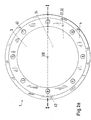
- Fig. 2a is a rear view, that is a plan view of the cathode bottom 34 of a vacuum arc evaporation source 1 shown, in which the magnetic reinforcing ring 4 is formed substantially by a plurality of permanent magnets 40.
- the permanent magnets 40 of the magnetic field enhancement ring 4 are arranged on the side facing away from the evaporation surface 33 at a predeterminable second distance A2 in front of the cathode bottom 34 and aligned substantially parallel or antiparallel to the surface normal 300 with respect to their magnetic polarization.
- all of the permanent magnets 40 may be aligned either parallel or anti-parallel with respect to the surfaces 300, or that a portion of the permanent magnets 40 may be parallel and another portion of the permanent magnets 40 may be aligned anti-parallel with respect to the surface normal 300, eg to realize special magnetic field geometries in the region of the cathode body 3.
- both the magnetic field enhancement ring 4, and / or the magnetic correction ring 5 and / or the magnetic field source 2 are e.g. may be formed by a ferrite or a ferromagnetic or a non-magnetic ring on which e.g. the plurality of parallel to the surface normal 300 aligned permanent magnets (20, 40, 50) are arranged, it being understood that the ferrite or the ferromagnetic or non-magnetic ring may also be absent.
- the magnet reinforcing ring 4 is formed by a ferritic ring on which three permanent magnets 40 are arranged at intervals of 120 °.
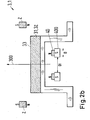
- Fig. 2b a section along the section line II through the cathode body 3 according to Fig. 2a shown.
- the annular magnetic field source 2 which is arranged directly above the evaporation surface 33 concentrically with the surface normal 3, can be seen.
- the ring magnet 2 may also be formed of a plurality of individual ring magnets 2 and / or may be formed by a plurality of permanent magnets 20 and / or realized by an electromagnet 2 can.
- the magnetic field reinforcing ring 4 comprises a magnetic or non-magnetic carrier ring 400, in which the permanent magnets 40 are preferably detachably provided, so that they are easily replaced, or as required the total number of permanent magnets 40 can be varied so that the strength and / or the geometry of the magnetic field caused by the magnetic field reinforcement ring 4 is very easily varied.
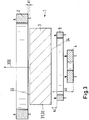
- FIG. 3 is a further, particularly important for practice according to the invention embodiment of a vacuum arc evaporation source 1 with a magnetic corrector ring 5 partially in section.
- the annular magnetic field source 2 is spaced at a distance A1 from the evaporation surface 33 of the cathode 3.
- the magnetic correction ring 5 is placed at a distance A2 slightly closer to the cathode bottom 34, as the magnetic reinforcement ring 4, which is spaced at a slightly greater distance A3 from the cathode bottom 34 is.
- the skilled person known per se means that allow, as required, the distances A1, A2 and A3 to change in a suitable manner.
- the magnetic field source 2, the magnetic field amplifying ring 4, and the magnetic correction ring 5 are magnetically polarized in the same direction with respect to the surface normal 300.
- the aforementioned magnetic rings may be disposed in any other suitable combination with respect to the surface normal 300. This can vary depending on the requirements and be determined, for example, by the relative strength of the magnets 2, 4, 5 used and / or the specific geometric arrangement with respect to the cathode body 3 or determined by other apparatus or procedural specifications.
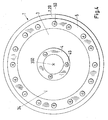
- Fig. 4 shows a rear view of another embodiment according to Fig. 3 in which the magnet reinforcing ring 4 and the magnetic correction ring 5 are formed by a plurality of permanent magnets 40, 50.
- the magnetic reinforcing ring 4 and the magnetic correction ring 5 have the same distance to the cathode bottom 34th
- FIG. 5 schematically an embodiment is shown, wherein the anode 9 via a BN insulation, ie via an electrically insulating layer which contains as an essential component boron nitride, ie BN, against an electrically conductive support block 7, which may for example consist of copper, electrically isolated.
- BN layer is known to me and serves mainly to prevent crosstalk of the arc to the anode 9 and the support block 7 in the operating state.
- the anode 9 can serve to ignite and maintain the arc during a coating process.
- an arc evaporation chamber 10 is schematically shown with a pivotable trigger device 14, wherein the trigger device 14 is electrically connected at a positive potential as an anode against the lying at a negative electric potential cathode body 3.
- the trigger device 14 serves in a manner known per se for igniting and maintaining an arc, and is, as shown by the arrow 141, both pivotable about an axis of rotation and linearly displaceable along the arrow 142 at a distance from the evaporation surface 33.
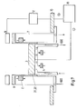
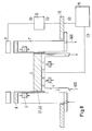
- the Fig. 7 and Fig. 8 each show an embodiment of an inventive arc evaporation chamber with isolated primary anode.
- the arc evaporation chamber 10 is connected in both examples to a positive pole of a power supply unit 11 and the cathode body 3 is connected to a negative pole of the power supply unit 11. That is, the arc evaporation chamber 10 is electrically connected as an anode with respect to the cathode body 3.
- the anode 9 is in each case embodied as a primary anode 9, which is electrically insulated from the carrier block 7. It is in the example of Fig. 7 the primary anode 9 is electrically coupled via an electrical resistance 12 to the arc vaporisation chamber 10, while in the example of FIG Fig. 8 the primary anode 9 is coupled via an auxiliary supply unit 13 in the manner known per se with the arc vaporisation chamber 10.
- a potential separation between primary anode 9 and arc evaporation chamber 10 can also be realized by the auxiliary supply unit 13 and the electrical resistance 12 between the support block 7 and the arc evaporation chamber 12 are arranged, the primary anode 9 then with the support block 7 is in electrical connection, or the carrier block 7 forms the primary anode 9 or directly includes.
- arc vaporisation chambers 10 By way of example two special embodiments of arc vaporisation chambers 10 according to the invention are shown, which are of particular importance for the practice. In particular, the arrangement of the polarities of individual evaporators for the case is described as an example when several evaporators are installed in the arc evaporation chamber 10.
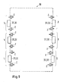
- FIG. 9 shows an arrangement with a first arc vaporisation chamber 10 with a plurality of arc vaporisation sources 1, which leads to a field amplification of opposing arc vaporisation sources 1 across the arc vaporisation chamber 10.
- arc evaporation sources 1 Preferably according to the representation underlying arc evaporation sources 1 mutually arranged with respect to their polarity. Due to the arrangement of the magnetic field field sources 2 with alternating polarity (for example, the N-pole is opposite to the S-pole), magnetic field lines are closed transversely through the arc evaporation chamber 10. This leads to a favorable influence on the excitation of reactive gases in the vicinity of the substrates to be coated, which for reasons of clarity in the Fig. 9 and 10 are not shown. By the arrangement of Fig. 9 the excitation of reactive gases in the vicinity of the substrates to be coated layer growth is positively influenced.
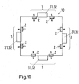
- FIG. 10 Another variant of an arc evaporation chamber 10 with a plurality of arc evaporation sources 1 is shown in FIG. 10.
- the evaporators 1 are located in a plane around the chamber 10. This mutual arrangement causes a field amplification according to FIG Fig. 9 does not occur across the chamber 10, but a closed magnetic field between the evaporators 1 is formed.
- This construction is preferable when additional excitation of the reactivity of the process gases in the vicinity of the substrates is undesirable, for example, when layers are to be deposited where a small proportion of reactive gases in the layers is desired.
- an inventive arc evaporation source can be used in many ways for coating a variety of workpieces. Using the usual reactive gases for example for the production of nitridic, carbidic, carbonitridic or oxynitridischen layers, as well as for Production of oxide layers or carbo-oxynitridischer layers or all other layers, which can be advantageously produced with an arc evaporation source.
- annular magnetic field source made possible by the massive construction of the support plate with holes for storage a selection of the number of magnets and the determination of their relative position A1. An anode is then optionally screwed onto the bore holes.
- the magnetic field reinforcement ring and the correction ring can be easily replaced, since the space behind the cathode bottom is designed freely.
- the rings themselves are preferably made of individual magnets, so that their number and polarity are adjustable. An adjustment of the distances to the cathode bottom or each other can be realized with simple mechanical sliding and clamping systems.
Landscapes
- Chemical & Material Sciences (AREA)
- Engineering & Computer Science (AREA)
- Physics & Mathematics (AREA)
- Plasma & Fusion (AREA)
- Analytical Chemistry (AREA)
- Chemical Kinetics & Catalysis (AREA)
- Materials Engineering (AREA)
- Mechanical Engineering (AREA)
- Metallurgy (AREA)
- Organic Chemistry (AREA)
- Physical Vapour Deposition (AREA)
Claims (10)
- Une chambre d'évaporation par arc avec une unité d'alimentation en énergie (11), et une source d'évaporation par arc sous vide (1), qui comprend un bloc de support (7) et une source de champ magnétique annulaire (2) disposée sur le bloc de support (7) et un corps de cathode (3) ayant un matériau d'évaporation (31) comme cathode (32) pour générer une décharge d'arc sur une surface d'évaporation (33) de la cathode (32), dans lequel le corps de cathode (3) est délimité dans une première direction axiale par un fond de cathode (34) et dans une seconde direction axiale par la surface d'évaporation (33) dans la direction axiale, et la source de champ magnétique annulaire (2) est polarisée parallèlement ou antiparallèlement à une normale de surface (300) de la surface d'évaporation (33) et est disposée concentriquement à la normale de surface (300) de la surface d'évaporation (33), avec un anneau d'amplification de champ magnétique (4) qui est disposé sur un côté opposé à la surface d'évaporation (33) à une seconde distance variable (A2) devant le fond de cathode (34), et avec une résistance électrique (12) et une anode primaire (9) qui est isolée électriquement du bloc de support (7), dans lequel la chambre d'évaporation par arc est reliée électriquement à l'anode primaire (9) via la résistance électrique (12), dans lequel la chambre d'évaporation par arc est reliée à un pôle positif de l'unité d'alimentation en énergie (11) et le corps de cathode (3) est relié à un pôle négatif de l'unité d'alimentation en énergie (11), caractérisé en ce que la source de champ magnétique (2) est espacée de la surface d'évaporation (33) à une première distance variable (A1) sur un côté du corps de cathode (3) opposé au fond (34) de la cathode.
- Une chambre d'évaporation par arc selon la revendication 1, dans lequel l'unité d'alimentation en énergie électrique (11) est une source d'énergie électrique à courant continu.
- Une chambre d'évaporation par arc selon la revendication 1, dans lequel l'unité d'alimentation en énergie électrique (11) est une source d'énergie électrique puisée.
- Une chambre d'évaporation par arc selon l'une des revendications précédentes, dans lequel une intensité de champ magnétique de la source de champ magnétique annulaire (2) ou une intensité de champ magnétique de l'anneau d'amplification de champ magnétique (4) ou une intensité de champ magnétique de l'anneau de correction magnétique (5) est variable ou contrôlable ou réglable, en particulier est contrôlable ou réglable en fonction du matériau évaporable (31) ou de l'état de combustion de la cathode (32) ou en fonction d'un autre paramètre de fonctionnement de la source d'évaporation par arc sous vide.
- Une chambre d'évaporation par arc selon la revendication 4, dans lequel l'intensité du champ magnétique est contrôlable ou réglable par une commande ou une régulation d'un courant électrique par un électroaimant de la source de champ magnétique annulaire (2) ou de l'anneau d'amplification de champ magnétique (4) ou de l'anneau de correction magnétique (5).
- Une chambre d'évaporation par arc selon l'une des revendications précédentes, dans lequel un système de refroidissement (6), en particulier un système de refroidissement à eau (6), est prévu pour refroidir la source d'évaporation par arc.
- Une chambre d'évaporation par arc selon l'une des revendications précédentes, dans lequel la source de champ magnétique annulaire (2) ou l'anneau d'amplification de champ magnétique (4) ou l'anneau de correction magnétique (5) comprend un aimant haute température, en particulier un aimant haute température en SmCo.
- Une chambre d'évaporation par arc selon l'une des revendications précédentes, dans lequel le bloc de support (7) est réalisé en cuivre et une isolation BN (8) est prévue entre le bloc de support (7) et la cathode (32) pour délimiter la décharge par arc sur la surface d'évaporation (33) de la cathode (32).
- Une chambre d'évaporation par arc selon la revendication 8, dans lequel l'isolation BN (8) est en contact tactile avec la cathode (32) pour l'allumage et la maintenance de la décharge par arc.
- Une chambre d'évaporation par arc selon l'une des revendications précédentes, dans lequel la source d'évaporation par arc comprend un dispositif de déclenchement pivotant (14) pour l'allumage de la décharge par arc, qui est particulièrement disposé de manière déplaçable linéairement et / ou de manière rotative.
Priority Applications (1)
| Application Number | Priority Date | Filing Date | Title |
|---|---|---|---|
| EP14150385.4A EP2720249B1 (fr) | 2007-04-17 | 2008-03-11 | Chambre de vaporisation d'arcs électriques dotée d'une source de vaporisation d'arcs électriques sous vide |
Applications Claiming Priority (4)
| Application Number | Priority Date | Filing Date | Title |
|---|---|---|---|
| EP07106345 | 2007-04-17 | ||
| PCT/EP2008/052844 WO2008125397A1 (fr) | 2007-04-17 | 2008-03-11 | Source d'évaporation sous vide à arc, ainsi qu'une chambre d'évaporation à arc comprenant une source d'évaporation sous vide à arc |
| EP08717591.5A EP2140476B1 (fr) | 2007-04-17 | 2008-03-11 | Source d'evaporation sous vide a arc, ainsi qu'une chambre d'evaporation a arc comprenant une source d'evaporation sous vide a arc |
| EP14150385.4A EP2720249B1 (fr) | 2007-04-17 | 2008-03-11 | Chambre de vaporisation d'arcs électriques dotée d'une source de vaporisation d'arcs électriques sous vide |
Related Parent Applications (2)
| Application Number | Title | Priority Date | Filing Date |
|---|---|---|---|
| EP08717591.5A Division EP2140476B1 (fr) | 2007-04-17 | 2008-03-11 | Source d'evaporation sous vide a arc, ainsi qu'une chambre d'evaporation a arc comprenant une source d'evaporation sous vide a arc |
| EP08717591.5A Division-Into EP2140476B1 (fr) | 2007-04-17 | 2008-03-11 | Source d'evaporation sous vide a arc, ainsi qu'une chambre d'evaporation a arc comprenant une source d'evaporation sous vide a arc |
Publications (3)
| Publication Number | Publication Date |
|---|---|
| EP2720249A2 EP2720249A2 (fr) | 2014-04-16 |
| EP2720249A3 EP2720249A3 (fr) | 2014-06-18 |
| EP2720249B1 true EP2720249B1 (fr) | 2019-07-10 |
Family
ID=39319667
Family Applications (3)
| Application Number | Title | Priority Date | Filing Date |
|---|---|---|---|
| EP08717591.5A Active EP2140476B1 (fr) | 2007-04-17 | 2008-03-11 | Source d'evaporation sous vide a arc, ainsi qu'une chambre d'evaporation a arc comprenant une source d'evaporation sous vide a arc |
| EP14150384.7A Active EP2720248B1 (fr) | 2007-04-17 | 2008-03-11 | Source de vaporisation d'arcs électriques à vide ainsi que chambre de vaporisation d'arcs électriques dotée d'une source de vaporisation d'arcs électriques à vide |
| EP14150385.4A Active EP2720249B1 (fr) | 2007-04-17 | 2008-03-11 | Chambre de vaporisation d'arcs électriques dotée d'une source de vaporisation d'arcs électriques sous vide |
Family Applications Before (2)
| Application Number | Title | Priority Date | Filing Date |
|---|---|---|---|
| EP08717591.5A Active EP2140476B1 (fr) | 2007-04-17 | 2008-03-11 | Source d'evaporation sous vide a arc, ainsi qu'une chambre d'evaporation a arc comprenant une source d'evaporation sous vide a arc |
| EP14150384.7A Active EP2720248B1 (fr) | 2007-04-17 | 2008-03-11 | Source de vaporisation d'arcs électriques à vide ainsi que chambre de vaporisation d'arcs électriques dotée d'une source de vaporisation d'arcs électriques à vide |
Country Status (9)
| Country | Link |
|---|---|
| US (1) | US9269545B2 (fr) |
| EP (3) | EP2140476B1 (fr) |
| JP (1) | JP5291086B2 (fr) |
| KR (2) | KR101698413B1 (fr) |
| CN (2) | CN101689468A (fr) |
| ES (3) | ES2575119T3 (fr) |
| HU (2) | HUE028868T2 (fr) |
| PL (2) | PL2720248T3 (fr) |
| WO (1) | WO2008125397A1 (fr) |
Families Citing this family (21)
| Publication number | Priority date | Publication date | Assignee | Title |
|---|---|---|---|---|
| DE102008057020A1 (de) | 2008-11-12 | 2010-05-20 | Oerlikon Trading Ag, Trübbach | Zündvorrichtung für Arc Quellen |
| JP5649308B2 (ja) * | 2009-04-28 | 2015-01-07 | 株式会社神戸製鋼所 | 成膜速度が速いアーク式蒸発源及びこのアーク式蒸発源を用いた皮膜の製造方法 |
| CN102985584B (zh) * | 2010-04-23 | 2016-01-20 | 苏舍梅塔普拉斯有限责任公司 | 用于金属机械加工的pvd涂层 |
| WO2011137967A1 (fr) * | 2010-05-04 | 2011-11-10 | Oerlikon Trading Ag, Trübbach | Procédé pour une évaporation par étincelle avec des cibles céramiques |
| JP5318052B2 (ja) | 2010-06-23 | 2013-10-16 | 株式会社神戸製鋼所 | 成膜速度が速いアーク式蒸発源、このアーク式蒸発源を用いた皮膜の製造方法及び成膜装置 |
| JP5644675B2 (ja) * | 2011-05-26 | 2014-12-24 | 三菱マテリアル株式会社 | アークイオンプレーティング装置および成膜方法 |
| JP5644676B2 (ja) * | 2011-05-26 | 2014-12-24 | 三菱マテリアル株式会社 | アークイオンプレーティング装置および成膜方法 |
| JP5652348B2 (ja) * | 2011-07-22 | 2015-01-14 | 三菱マテリアル株式会社 | アークイオンプレーティング装置 |
| UA101443C2 (ru) * | 2011-11-29 | 2013-03-25 | Национальный Научный Центр "Харьковский Физико-Технический Институт" | Анодный УЗЕЛ вакуумно-дугового ИСТОЧНИКа катодной ПЛАЗМЫ |
| JP5946337B2 (ja) * | 2012-06-20 | 2016-07-06 | 株式会社神戸製鋼所 | アーク式蒸発源 |
| EP2746424B1 (fr) * | 2012-12-21 | 2018-10-17 | Oerlikon Surface Solutions AG, Pfäffikon | Source d'évaporation |
| JP6403269B2 (ja) * | 2014-07-30 | 2018-10-10 | 株式会社神戸製鋼所 | アーク蒸発源 |
| JP2018028109A (ja) * | 2014-12-22 | 2018-02-22 | 旭硝子株式会社 | プラズマcvd装置 |
| SG10201705059TA (en) | 2016-06-24 | 2018-01-30 | Veeco Instr Inc | Enhanced cathodic arc source for arc plasma deposition |
| CN110268502B (zh) * | 2017-02-14 | 2021-08-24 | 欧瑞康表面处理解决方案股份公司普费菲孔 | 具有预定阴极材料蚀除的阴极电弧蒸发 |
| TWM597506U (zh) | 2018-04-13 | 2020-06-21 | 美商維高儀器股份有限公司 | 具有多區域噴射器塊的化學氣相沉積設備 |
| CN110846623A (zh) * | 2019-12-12 | 2020-02-28 | 大连理工大学 | 一种用于提高金属蒸发镀膜均匀性的装置及方法 |
| CN111621751B (zh) * | 2020-05-15 | 2023-03-21 | 温州职业技术学院 | 一种多模式调制弧源装置 |
| CN114657518A (zh) * | 2022-02-24 | 2022-06-24 | 北京茂孚工业控制技术中心 | 带有多级可控复合磁场电弧离子源的难溶金属沉积设备 |
| KR102529505B1 (ko) * | 2022-06-08 | 2023-05-10 | 주식회사 한국나노오트 | 세리아 입자 제조 장치 및 이를 이용한 세리아 입자의 제조방법 |
| KR102925733B1 (ko) * | 2023-02-02 | 2026-02-11 | 주식회사 한국나노오트 | 나노 입자 제조장치 및 이를 이용한 나노 입자의 제조방법 |
Citations (1)
| Publication number | Priority date | Publication date | Assignee | Title |
|---|---|---|---|---|
| DE19739527A1 (de) * | 1997-09-09 | 1999-03-11 | Rossendorf Forschzent | Vakuumbogen-Plasmaquelle mit Magnet-Partikelfilter |
Family Cites Families (26)
| Publication number | Priority date | Publication date | Assignee | Title |
|---|---|---|---|---|
| JPS54120696A (en) | 1978-03-10 | 1979-09-19 | Takeda Chem Ind Ltd | Glucosamine derivative and its preparation |
| JPS6247477A (ja) * | 1985-08-28 | 1987-03-02 | Tokuda Seisakusho Ltd | スパツタリング装置 |
| US4620913A (en) * | 1985-11-15 | 1986-11-04 | Multi-Arc Vacuum Systems, Inc. | Electric arc vapor deposition method and apparatus |
| JPS63446U (fr) * | 1986-06-19 | 1988-01-05 | ||
| US5298136A (en) * | 1987-08-18 | 1994-03-29 | Regents Of The University Of Minnesota | Steered arc coating with thick targets |
| EP0334204B1 (fr) * | 1988-03-23 | 1995-04-19 | Balzers Aktiengesellschaft | Procédé et dispositif de revêtement d'objets |
| JP2851320B2 (ja) | 1988-09-26 | 1999-01-27 | 株式会社神戸製鋼所 | 真空アーク蒸着装置及び方法 |
| DD293145A5 (de) | 1989-03-23 | 1991-08-22 | Tu Chemnitz,De | Verfahren zur herstellung von mehrkomponentenschichten |
| DD285463A5 (de) | 1989-06-22 | 1990-12-12 | Veb Hochvakuum Dresden,Dd | Verfahren zur regelung der brennfleckpostion bei einem vakuumbogenverdampfer |
| JPH0445262A (ja) * | 1990-06-12 | 1992-02-14 | Kobe Steel Ltd | 真空アーク蒸着装置 |
| JPH04236770A (ja) | 1991-01-17 | 1992-08-25 | Kobe Steel Ltd | 真空アーク蒸着のアークスポットの制御方法及び蒸発源 |
| JPH063446A (ja) | 1992-06-23 | 1994-01-11 | Meidensha Corp | 位置センサ |
| DE4223592C2 (de) * | 1992-06-24 | 2001-05-17 | Leybold Ag | Lichtbogen-Verdampfungsvorrichtung |
| JP3924832B2 (ja) * | 1997-02-19 | 2007-06-06 | 日新電機株式会社 | 真空アーク蒸着装置 |
| US6103074A (en) | 1998-02-14 | 2000-08-15 | Phygen, Inc. | Cathode arc vapor deposition method and apparatus |
| JP3728140B2 (ja) | 1999-05-21 | 2005-12-21 | 株式会社神戸製鋼所 | アーク蒸発源及び真空蒸着装置 |
| TWI242049B (en) | 1999-01-14 | 2005-10-21 | Kobe Steel Ltd | Vacuum arc evaporation source and vacuum arc vapor deposition apparatus |
| US6929727B2 (en) * | 1999-04-12 | 2005-08-16 | G & H Technologies, Llc | Rectangular cathodic arc source and method of steering an arc spot |
| JP3917348B2 (ja) | 1999-05-26 | 2007-05-23 | 株式会社神戸製鋼所 | アーク蒸発源、真空蒸着装置及び真空蒸着方法 |
| CN100355933C (zh) * | 2001-03-27 | 2007-12-19 | 特克尼克基业 | 具有用于较大表面积的靶的强力磁引导装置的电弧蒸发器 |
| FR2837979A1 (fr) * | 2002-03-27 | 2003-10-03 | Thomson Licensing Sa | Dispositif magnetique de correction des defauts de geometrie d'image pour tubes a rayons cathodiques |
| JP4109503B2 (ja) * | 2002-07-22 | 2008-07-02 | 日新電機株式会社 | 真空アーク蒸着装置 |
| KR101074554B1 (ko) | 2002-12-19 | 2011-10-17 | 오를리콘 트레이딩 아크티엔게젤샤프트, 트뤼프바흐 | 자기장 발생 장치를 포함하는 진공 아크 공급 장치 |
| JP4344640B2 (ja) * | 2004-03-31 | 2009-10-14 | 株式会社栗田製作所 | 真空アーク蒸発装置およびその運転方法 |
| US9997338B2 (en) * | 2005-03-24 | 2018-06-12 | Oerlikon Surface Solutions Ag, Pfäffikon | Method for operating a pulsed arc source |
| US7857948B2 (en) * | 2006-07-19 | 2010-12-28 | Oerlikon Trading Ag, Trubbach | Method for manufacturing poorly conductive layers |
-
2008
- 2008-03-11 JP JP2010503437A patent/JP5291086B2/ja not_active Expired - Fee Related
- 2008-03-11 ES ES08717591.5T patent/ES2575119T3/es active Active
- 2008-03-11 PL PL14150384T patent/PL2720248T3/pl unknown
- 2008-03-11 PL PL08717591.5T patent/PL2140476T3/pl unknown
- 2008-03-11 KR KR1020167007309A patent/KR101698413B1/ko not_active Expired - Fee Related
- 2008-03-11 EP EP08717591.5A patent/EP2140476B1/fr active Active
- 2008-03-11 ES ES14150384.7T patent/ES2648995T3/es active Active
- 2008-03-11 HU HUE08717591A patent/HUE028868T2/en unknown
- 2008-03-11 EP EP14150384.7A patent/EP2720248B1/fr active Active
- 2008-03-11 HU HUE14150384A patent/HUE037336T2/hu unknown
- 2008-03-11 CN CN200880012612A patent/CN101689468A/zh active Pending
- 2008-03-11 KR KR1020097021620A patent/KR101641991B1/ko active Active
- 2008-03-11 EP EP14150385.4A patent/EP2720249B1/fr active Active
- 2008-03-11 ES ES14150385T patent/ES2749721T3/es active Active
- 2008-03-11 WO PCT/EP2008/052844 patent/WO2008125397A1/fr not_active Ceased
- 2008-03-11 US US12/595,273 patent/US9269545B2/en active Active
- 2008-03-11 CN CN201510805806.2A patent/CN105632859B/zh active Active
Patent Citations (1)
| Publication number | Priority date | Publication date | Assignee | Title |
|---|---|---|---|---|
| DE19739527A1 (de) * | 1997-09-09 | 1999-03-11 | Rossendorf Forschzent | Vakuumbogen-Plasmaquelle mit Magnet-Partikelfilter |
Also Published As
| Publication number | Publication date |
|---|---|
| PL2720248T3 (pl) | 2018-01-31 |
| EP2720248A3 (fr) | 2014-06-18 |
| HUE028868T2 (en) | 2017-01-30 |
| ES2575119T3 (es) | 2016-06-24 |
| KR101641991B1 (ko) | 2016-07-29 |
| KR20100015634A (ko) | 2010-02-12 |
| CN105632859B (zh) | 2018-03-30 |
| US20100213055A1 (en) | 2010-08-26 |
| ES2749721T3 (es) | 2020-03-23 |
| EP2720249A3 (fr) | 2014-06-18 |
| EP2140476A1 (fr) | 2010-01-06 |
| KR20160036094A (ko) | 2016-04-01 |
| EP2140476B1 (fr) | 2016-05-18 |
| JP2010525158A (ja) | 2010-07-22 |
| US9269545B2 (en) | 2016-02-23 |
| EP2720248B1 (fr) | 2017-08-23 |
| CN101689468A (zh) | 2010-03-31 |
| CN105632859A (zh) | 2016-06-01 |
| HUE037336T2 (hu) | 2018-08-28 |
| PL2140476T3 (pl) | 2016-11-30 |
| KR101698413B1 (ko) | 2017-01-20 |
| EP2720249A2 (fr) | 2014-04-16 |
| EP2720248A2 (fr) | 2014-04-16 |
| ES2648995T3 (es) | 2018-01-09 |
| JP5291086B2 (ja) | 2013-09-18 |
| WO2008125397A1 (fr) | 2008-10-23 |
Similar Documents
| Publication | Publication Date | Title |
|---|---|---|
| EP2720249B1 (fr) | Chambre de vaporisation d'arcs électriques dotée d'une source de vaporisation d'arcs électriques sous vide | |
| EP2018653B1 (fr) | Source d'arc et arrangement d'aimants | |
| EP2041331B1 (fr) | Procédé pour le dépôt de couches électriquement isolantes | |
| EP2795657B1 (fr) | Dispositif pour décharge de plasma avec un cathode creuse | |
| WO2008067969A1 (fr) | Installation de revêtement sous vide pour revêtement pvd homogène | |
| DE10084452B3 (de) | Lichtbogenquelle mit rechteckiger Kathode und Verfahren zur Lenkung eines Lichtbogenflecks | |
| EP2778253B1 (fr) | Source d'évaporation cylindrique | |
| EP2159821A2 (fr) | Dispositif de revêtement destiné au revêtement d'un substrat et procédé de revêtement d'un substrat | |
| EP1576641B1 (fr) | Source d'arc sous vide comprenant un dispositif de production de champ magnetique | |
| WO2011160766A1 (fr) | Source d'évaporation par arc présentant un champ électrique défini | |
| WO2010088947A1 (fr) | Configuration d'aimant modifiable pour sources de vaporisation à arc | |
| DE3615361A1 (de) | Vorrichtung zur oberflaechenbehandlung von werkstuecken | |
| EP2175044B1 (fr) | Procédé de revêtement PVD, dispositif d'exécution du procédé et substances revêtues selon ce procédé | |
| DE102006020004A1 (de) | Vorrichtung und Verfahren zur homogenen PVD-Beschichtung | |
| DE10250941B4 (de) | Quelle für Vakuumbehandlungsprozess sowie Verfahren zum Betreiben einer solchen | |
| WO2000016373A1 (fr) | Ensemble cible pour chambre d'evaporation par l'intermediaire d'un arc | |
| EP3900011B1 (fr) | Ensemble aimant conçu pour une source de plasma pour réaliser des traitement au plasma | |
| DE10234858A1 (de) | Einrichtung zur Erzeugung einer Magnetron-Entladung | |
| DE69808267T2 (de) | Verfahren und vorrichtung für pvd beschichtung | |
| EP3583619B1 (fr) | Évaporation par arc cathodique avec enlèvement de matière à la cathode prédéfini | |
| EP1473382A1 (fr) | Procédé et dispositif de déposition d'une couche activée par plasma par pulvérisation magnétron | |
| CH702969A2 (de) | Segmentierte Anode. | |
| DE102012106403B4 (de) | Verfahren zum reaktiven Magnetronsputtern zur Beschichtung von Substraten | |
| DE10318363A1 (de) | Verfahren und Einrichtung zum plasmaaktivierten Hochrate-Bedampfen großflächiger Substrate | |
| DE10058768C2 (de) | Verfahren zum Zünden eines Plasmas |
Legal Events
| Date | Code | Title | Description |
|---|---|---|---|
| PUAI | Public reference made under article 153(3) epc to a published international application that has entered the european phase |
Free format text: ORIGINAL CODE: 0009012 |
|
| AC | Divisional application: reference to earlier application |
Ref document number: 2140476 Country of ref document: EP Kind code of ref document: P |
|
| AK | Designated contracting states |
Kind code of ref document: A2 Designated state(s): AT BE BG CH CY CZ DE DK EE ES FI FR GB GR HR HU IE IS IT LI LT LU LV MC MT NL NO PL PT RO SE SI SK TR |
|
| PUAL | Search report despatched |
Free format text: ORIGINAL CODE: 0009013 |
|
| AK | Designated contracting states |
Kind code of ref document: A3 Designated state(s): AT BE BG CH CY CZ DE DK EE ES FI FR GB GR HR HU IE IS IT LI LT LU LV MC MT NL NO PL PT RO SE SI SK TR |
|
| RIC1 | Information provided on ipc code assigned before grant |
Ipc: H01J 37/305 20060101AFI20140512BHEP Ipc: H01J 37/32 20060101ALI20140512BHEP |
|
| 17P | Request for examination filed |
Effective date: 20141218 |
|
| RBV | Designated contracting states (corrected) |
Designated state(s): AT BE BG CH CY CZ DE DK EE ES FI FR GB GR HR HU IE IS IT LI LT LU LV MC MT NL NO PL PT RO SE SI SK TR |
|
| STAA | Information on the status of an ep patent application or granted ep patent |
Free format text: STATUS: EXAMINATION IS IN PROGRESS |
|
| 17Q | First examination report despatched |
Effective date: 20170210 |
|
| GRAP | Despatch of communication of intention to grant a patent |
Free format text: ORIGINAL CODE: EPIDOSNIGR1 |
|
| STAA | Information on the status of an ep patent application or granted ep patent |
Free format text: STATUS: GRANT OF PATENT IS INTENDED |
|
| INTG | Intention to grant announced |
Effective date: 20190219 |
|
| RAP1 | Party data changed (applicant data changed or rights of an application transferred) |
Owner name: OERLIKON SURFACE SOLUTIONS AG, PFAEFFIKON |
|
| GRAS | Grant fee paid |
Free format text: ORIGINAL CODE: EPIDOSNIGR3 |
|
| GRAA | (expected) grant |
Free format text: ORIGINAL CODE: 0009210 |
|
| STAA | Information on the status of an ep patent application or granted ep patent |
Free format text: STATUS: THE PATENT HAS BEEN GRANTED |
|
| AC | Divisional application: reference to earlier application |
Ref document number: 2140476 Country of ref document: EP Kind code of ref document: P |
|
| AK | Designated contracting states |
Kind code of ref document: B1 Designated state(s): AT BE BG CH CY CZ DE DK EE ES FI FR GB GR HR HU IE IS IT LI LT LU LV MC MT NL NO PL PT RO SE SI SK TR |
|
| REG | Reference to a national code |
Ref country code: GB Ref legal event code: FG4D Free format text: NOT ENGLISH |
|
| REG | Reference to a national code |
Ref country code: CH Ref legal event code: EP Ref country code: AT Ref legal event code: REF Ref document number: 1154429 Country of ref document: AT Kind code of ref document: T Effective date: 20190715 |
|
| REG | Reference to a national code |
Ref country code: DE Ref legal event code: R096 Ref document number: 502008016844 Country of ref document: DE |
|
| REG | Reference to a national code |
Ref country code: IE Ref legal event code: FG4D Free format text: LANGUAGE OF EP DOCUMENT: GERMAN |
|
| REG | Reference to a national code |
Ref country code: SE Ref legal event code: TRGR |
|
| REG | Reference to a national code |
Ref country code: NL Ref legal event code: FP |
|
| REG | Reference to a national code |
Ref country code: LT Ref legal event code: MG4D |
|
| PG25 | Lapsed in a contracting state [announced via postgrant information from national office to epo] |
Ref country code: NO Free format text: LAPSE BECAUSE OF FAILURE TO SUBMIT A TRANSLATION OF THE DESCRIPTION OR TO PAY THE FEE WITHIN THE PRESCRIBED TIME-LIMIT Effective date: 20191010 Ref country code: FI Free format text: LAPSE BECAUSE OF FAILURE TO SUBMIT A TRANSLATION OF THE DESCRIPTION OR TO PAY THE FEE WITHIN THE PRESCRIBED TIME-LIMIT Effective date: 20190710 Ref country code: HR Free format text: LAPSE BECAUSE OF FAILURE TO SUBMIT A TRANSLATION OF THE DESCRIPTION OR TO PAY THE FEE WITHIN THE PRESCRIBED TIME-LIMIT Effective date: 20190710 Ref country code: BG Free format text: LAPSE BECAUSE OF FAILURE TO SUBMIT A TRANSLATION OF THE DESCRIPTION OR TO PAY THE FEE WITHIN THE PRESCRIBED TIME-LIMIT Effective date: 20191010 Ref country code: PT Free format text: LAPSE BECAUSE OF FAILURE TO SUBMIT A TRANSLATION OF THE DESCRIPTION OR TO PAY THE FEE WITHIN THE PRESCRIBED TIME-LIMIT Effective date: 20191111 Ref country code: LT Free format text: LAPSE BECAUSE OF FAILURE TO SUBMIT A TRANSLATION OF THE DESCRIPTION OR TO PAY THE FEE WITHIN THE PRESCRIBED TIME-LIMIT Effective date: 20190710 |
|
| PG25 | Lapsed in a contracting state [announced via postgrant information from national office to epo] |
Ref country code: GR Free format text: LAPSE BECAUSE OF FAILURE TO SUBMIT A TRANSLATION OF THE DESCRIPTION OR TO PAY THE FEE WITHIN THE PRESCRIBED TIME-LIMIT Effective date: 20191011 Ref country code: LV Free format text: LAPSE BECAUSE OF FAILURE TO SUBMIT A TRANSLATION OF THE DESCRIPTION OR TO PAY THE FEE WITHIN THE PRESCRIBED TIME-LIMIT Effective date: 20190710 Ref country code: IS Free format text: LAPSE BECAUSE OF FAILURE TO SUBMIT A TRANSLATION OF THE DESCRIPTION OR TO PAY THE FEE WITHIN THE PRESCRIBED TIME-LIMIT Effective date: 20191110 |
|
| REG | Reference to a national code |
Ref country code: ES Ref legal event code: FG2A Ref document number: 2749721 Country of ref document: ES Kind code of ref document: T3 Effective date: 20200323 |
|
| PG25 | Lapsed in a contracting state [announced via postgrant information from national office to epo] |
Ref country code: RO Free format text: LAPSE BECAUSE OF FAILURE TO SUBMIT A TRANSLATION OF THE DESCRIPTION OR TO PAY THE FEE WITHIN THE PRESCRIBED TIME-LIMIT Effective date: 20190710 Ref country code: PL Free format text: LAPSE BECAUSE OF FAILURE TO SUBMIT A TRANSLATION OF THE DESCRIPTION OR TO PAY THE FEE WITHIN THE PRESCRIBED TIME-LIMIT Effective date: 20190710 Ref country code: DK Free format text: LAPSE BECAUSE OF FAILURE TO SUBMIT A TRANSLATION OF THE DESCRIPTION OR TO PAY THE FEE WITHIN THE PRESCRIBED TIME-LIMIT Effective date: 20190710 Ref country code: EE Free format text: LAPSE BECAUSE OF FAILURE TO SUBMIT A TRANSLATION OF THE DESCRIPTION OR TO PAY THE FEE WITHIN THE PRESCRIBED TIME-LIMIT Effective date: 20190710 |
|
| PG25 | Lapsed in a contracting state [announced via postgrant information from national office to epo] |
Ref country code: CZ Free format text: LAPSE BECAUSE OF FAILURE TO SUBMIT A TRANSLATION OF THE DESCRIPTION OR TO PAY THE FEE WITHIN THE PRESCRIBED TIME-LIMIT Effective date: 20190710 Ref country code: IS Free format text: LAPSE BECAUSE OF FAILURE TO SUBMIT A TRANSLATION OF THE DESCRIPTION OR TO PAY THE FEE WITHIN THE PRESCRIBED TIME-LIMIT Effective date: 20200224 Ref country code: SK Free format text: LAPSE BECAUSE OF FAILURE TO SUBMIT A TRANSLATION OF THE DESCRIPTION OR TO PAY THE FEE WITHIN THE PRESCRIBED TIME-LIMIT Effective date: 20190710 |
|
| REG | Reference to a national code |
Ref country code: DE Ref legal event code: R097 Ref document number: 502008016844 Country of ref document: DE |
|
| PLBE | No opposition filed within time limit |
Free format text: ORIGINAL CODE: 0009261 |
|
| STAA | Information on the status of an ep patent application or granted ep patent |
Free format text: STATUS: NO OPPOSITION FILED WITHIN TIME LIMIT |
|
| PG2D | Information on lapse in contracting state deleted |
Ref country code: IS |
|
| 26N | No opposition filed |
Effective date: 20200603 |
|
| PG25 | Lapsed in a contracting state [announced via postgrant information from national office to epo] |
Ref country code: SI Free format text: LAPSE BECAUSE OF FAILURE TO SUBMIT A TRANSLATION OF THE DESCRIPTION OR TO PAY THE FEE WITHIN THE PRESCRIBED TIME-LIMIT Effective date: 20190710 |
|
| PG25 | Lapsed in a contracting state [announced via postgrant information from national office to epo] |
Ref country code: MC Free format text: LAPSE BECAUSE OF FAILURE TO SUBMIT A TRANSLATION OF THE DESCRIPTION OR TO PAY THE FEE WITHIN THE PRESCRIBED TIME-LIMIT Effective date: 20190710 |
|
| REG | Reference to a national code |
Ref country code: BE Ref legal event code: MM Effective date: 20200331 |
|
| PG25 | Lapsed in a contracting state [announced via postgrant information from national office to epo] |
Ref country code: IE Free format text: LAPSE BECAUSE OF NON-PAYMENT OF DUE FEES Effective date: 20200311 |
|
| PG25 | Lapsed in a contracting state [announced via postgrant information from national office to epo] |
Ref country code: BE Free format text: LAPSE BECAUSE OF NON-PAYMENT OF DUE FEES Effective date: 20200331 |
|
| PGFP | Annual fee paid to national office [announced via postgrant information from national office to epo] |
Ref country code: GB Payment date: 20220322 Year of fee payment: 15 |
|
| PG25 | Lapsed in a contracting state [announced via postgrant information from national office to epo] |
Ref country code: MT Free format text: LAPSE BECAUSE OF FAILURE TO SUBMIT A TRANSLATION OF THE DESCRIPTION OR TO PAY THE FEE WITHIN THE PRESCRIBED TIME-LIMIT Effective date: 20190710 Ref country code: CY Free format text: LAPSE BECAUSE OF FAILURE TO SUBMIT A TRANSLATION OF THE DESCRIPTION OR TO PAY THE FEE WITHIN THE PRESCRIBED TIME-LIMIT Effective date: 20190710 |
|
| PGFP | Annual fee paid to national office [announced via postgrant information from national office to epo] |
Ref country code: TR Payment date: 20220301 Year of fee payment: 15 Ref country code: LU Payment date: 20220325 Year of fee payment: 15 |
|
| PGFP | Annual fee paid to national office [announced via postgrant information from national office to epo] |
Ref country code: ES Payment date: 20220418 Year of fee payment: 15 |
|
| GBPC | Gb: european patent ceased through non-payment of renewal fee |
Effective date: 20230311 |
|
| PG25 | Lapsed in a contracting state [announced via postgrant information from national office to epo] |
Ref country code: LU Free format text: LAPSE BECAUSE OF NON-PAYMENT OF DUE FEES Effective date: 20230311 |
|
| PG25 | Lapsed in a contracting state [announced via postgrant information from national office to epo] |
Ref country code: GB Free format text: LAPSE BECAUSE OF NON-PAYMENT OF DUE FEES Effective date: 20230311 |
|
| PG25 | Lapsed in a contracting state [announced via postgrant information from national office to epo] |
Ref country code: GB Free format text: LAPSE BECAUSE OF NON-PAYMENT OF DUE FEES Effective date: 20230311 |
|
| PG25 | Lapsed in a contracting state [announced via postgrant information from national office to epo] |
Ref country code: ES Free format text: LAPSE BECAUSE OF NON-PAYMENT OF DUE FEES Effective date: 20230312 |
|
| REG | Reference to a national code |
Ref country code: ES Ref legal event code: FD2A Effective date: 20240426 |
|
| PG25 | Lapsed in a contracting state [announced via postgrant information from national office to epo] |
Ref country code: ES Free format text: LAPSE BECAUSE OF NON-PAYMENT OF DUE FEES Effective date: 20230312 |
|
| PGFP | Annual fee paid to national office [announced via postgrant information from national office to epo] |
Ref country code: CH Payment date: 20250401 Year of fee payment: 18 |
|
| REG | Reference to a national code |
Ref country code: CH Ref legal event code: U11 Free format text: ST27 STATUS EVENT CODE: U-0-0-U10-U11 (AS PROVIDED BY THE NATIONAL OFFICE) Effective date: 20260401 |
|
| PGFP | Annual fee paid to national office [announced via postgrant information from national office to epo] |
Ref country code: SE Payment date: 20260323 Year of fee payment: 19 |
|
| PGFP | Annual fee paid to national office [announced via postgrant information from national office to epo] |
Ref country code: DE Payment date: 20260320 Year of fee payment: 19 |
|
| PGFP | Annual fee paid to national office [announced via postgrant information from national office to epo] |
Ref country code: AT Payment date: 20260318 Year of fee payment: 19 |
|
| PGFP | Annual fee paid to national office [announced via postgrant information from national office to epo] |
Ref country code: IT Payment date: 20260320 Year of fee payment: 19 |
|
| PGFP | Annual fee paid to national office [announced via postgrant information from national office to epo] |
Ref country code: NL Payment date: 20260323 Year of fee payment: 19 |
|
| PGFP | Annual fee paid to national office [announced via postgrant information from national office to epo] |
Ref country code: FR Payment date: 20260323 Year of fee payment: 19 |