EP1576641B1 - Source d'arc sous vide comprenant un dispositif de production de champ magnetique - Google Patents
Source d'arc sous vide comprenant un dispositif de production de champ magnetique Download PDFInfo
- Publication number
- EP1576641B1 EP1576641B1 EP03753214A EP03753214A EP1576641B1 EP 1576641 B1 EP1576641 B1 EP 1576641B1 EP 03753214 A EP03753214 A EP 03753214A EP 03753214 A EP03753214 A EP 03753214A EP 1576641 B1 EP1576641 B1 EP 1576641B1
- Authority
- EP
- European Patent Office
- Prior art keywords
- target
- magnetic field
- coil
- arc source
- arc
- Prior art date
- Legal status (The legal status is an assumption and is not a legal conclusion. Google has not performed a legal analysis and makes no representation as to the accuracy of the status listed.)
- Expired - Lifetime
Links
Images


Classifications
-
- H—ELECTRICITY
- H01—ELECTRIC ELEMENTS
- H01J—ELECTRIC DISCHARGE TUBES OR DISCHARGE LAMPS
- H01J37/00—Discharge tubes with provision for introducing objects or material to be exposed to the discharge, e.g. for the purpose of examination or processing thereof
- H01J37/32—Gas-filled discharge tubes
- H01J37/32009—Arrangements for generation of plasma specially adapted for examination or treatment of objects, e.g. plasma sources
- H01J37/32055—Arc discharge
-
- H—ELECTRICITY
- H01—ELECTRIC ELEMENTS
- H01J—ELECTRIC DISCHARGE TUBES OR DISCHARGE LAMPS
- H01J37/00—Discharge tubes with provision for introducing objects or material to be exposed to the discharge, e.g. for the purpose of examination or processing thereof
- H01J37/32—Gas-filled discharge tubes
- H01J37/34—Gas-filled discharge tubes operating with cathodic sputtering
- H01J37/3411—Constructional aspects of the reactor
- H01J37/3414—Targets
-
- H—ELECTRICITY
- H01—ELECTRIC ELEMENTS
- H01J—ELECTRIC DISCHARGE TUBES OR DISCHARGE LAMPS
- H01J37/00—Discharge tubes with provision for introducing objects or material to be exposed to the discharge, e.g. for the purpose of examination or processing thereof
- H01J37/32—Gas-filled discharge tubes
- H01J37/34—Gas-filled discharge tubes operating with cathodic sputtering
- H01J37/3411—Constructional aspects of the reactor
- H01J37/345—Magnet arrangements in particular for cathodic sputtering apparatus
- H01J37/3452—Magnet distribution
-
- H—ELECTRICITY
- H01—ELECTRIC ELEMENTS
- H01J—ELECTRIC DISCHARGE TUBES OR DISCHARGE LAMPS
- H01J2237/00—Discharge tubes exposing object to beam, e.g. for analysis treatment, etching, imaging
- H01J2237/32—Processing objects by plasma generation
- H01J2237/327—Arrangements for generating the plasma
Definitions
- the present invention relates to a vacuum arc source for operating an arc discharge according to claim 1, a system equipped with such an arc source according to claim 17, and a method for operating an arc discharge according to claim 21.
- Arc sources such as are known in a vacuum chamber for vaporizing different materials and / or as an ion source, are used for coating and pretreating different workpieces. Due to the high point-like introduced energy of running on the target surface of the arc, referred to in the following arc, it comes in addition to the emission of gaseous, largely ionized particles, especially in a "firing" of the spark with the result of explosive evaporation, also for Emission of macroparticles whose diameter can reach up to a few microns and more. After coating, the surface roughness of, for example, polished workpieces is thus determined essentially by the number and size of the macroparticles adhering to the layer surface or grown into the layer.
- the layers thus deposited are relatively rough, which adversely affects the application of a coated tool or component. Furthermore, a majority of the macroparticles leave the surface of the target at a relatively shallow angle, thereby losing valuable material in coating processes, which deposits on the inner surfaces of the vacuum chamber.
- An arc source disclosed therein shows a circular target which is encompassed laterally from behind by a cup-shaped pole piece having a central pole piece guided up to the target rear side and a coil arranged therebetween.
- a magnetic field is generated above the target, the vertical component of which has a positive maximum in the center of the target, decreases symmetrically to smaller values up to a negative minimum in the edge region, and then asymptotically increases again in the direction of the abscissa.
- Similar magnetic fields can also be generated in a known manner by arranging permanent magnets on the back of the target.
- the passage of the field lines is defined by the abscissa (ie zero crossing corresponding to a change of the field direction) on the target surface a self-contained (circular) line on which the vertical component of the magnetic field is zero.
- the spark arriving at the target from the plasma into the target for example in the case of a cathodically switched target, experiences no radial acceleration, but a high tangential acceleration, since the parallel component of the magnetic field has a maximum on the same line.
- the high rotational speed of the spark achieved in this manner effectively prevents "seizure", but at the same time causes poor target utilization, since essentially only a narrow circular ring of the target is removed.
- a solenoid coil comprising the target and the pole piece in the upper region has been provided with which the radius of the zero line generated by the pole piece and the coil arranged therein can be radially displaced.
- the technical effort required for this is relatively large, since an independent current / voltage control unit has to be provided for each of the two coils, wherein at least one of them must be suitable for delivering time-variable current / voltage signals to a periodic expansion / contraction of the zero line on the Enable target.
- a relatively large area in the center of the target is only slightly or not removed even in the case of such an arc source.
- the object of the present invention is to eliminate the mentioned disadvantages of the prior art.
- the magnetic field component B ⁇ less than 30, preferably less than 20, more preferably less than 10 Gauss is selected.
- the values B ⁇ R of the perpendicular magnetic field component with respect to the values B ⁇ in the middle region of the target surface may be increased, decreased and / or the sign alternately set.
- the majority of the surface ie the region in which the vertical component B ⁇ extends substantially constantly close to zero, advantageously extends from a central region of the target surface to an edge region and comprises at least 50%, but preferably at least 60% of the or the geometrically determining measures.
- the values B ⁇ R of the perpendicular magnetic field component with respect to the values B ⁇ in the middle region of the target surface may be increased, decreased and / or the sign alternately set.
- the value of the parallel magnetic field component B ll can also be set in the middle substantially to zero, but increasing in the direction of the edge of the target surface, preferably increasing symmetrically with respect to the target center.
- a magnetic field with an approximately linearly increasing component B ll When applied, the force acting tangentially clockwise or counterclockwise on the sparks increases towards the edge of the target, allowing the spark to travel over the radius at approximately constant angular velocity.
- Such a magnetic field may be produced with a vacuum arc source having a magnetic field generating device comprising at least two oppositely poled magnet systems.
- the at least two oppositely poled magnet system e for example, a mounted behind the target first electromagnetic coil can be provided, which in turn can be constructed from a plurality of coils.
- the inner dimensions of the first coil substantially coincide with a deviation of at most plus / minus 30%, preferably plus / minus 20% with the projection of the outer dimensions of the surface of the target.
- the magnetic fields thus generated at the target surface should correspond approximately to a field of a solenoid coil constructed as above, so be relatively small. Therefore, the permanent magnets should either have a low field strength of their own or be spaced apart from the target. Furthermore, it should be noted that here as well as when using a coil as described above, a reversal of the field direction at the target surface is not already effected by the first magnet system. A known from the prior art arrangement with, for example, alternating polarity between the center and edge area is therefore to be avoided.
- Plastoferrit magnets depending on the field strength to be set in the form of single or multi-layer discs or Planecke, as uniform as possible on the back of the target, analogous to above up to a range of plus / minus 30 %, preferably plus / minus 20% of the outer dimensions of the surface of the target can be attached.
- a second magnet system is advantageously provided at least one of the first magnetic system comprehensive or coaxially arranged coil.
- This can for example be arranged laterally encompassing the first magnet system or target, or preferably behind the first magnet system or target.
- a second coil arranged behind the first magnet system it is also advantageous to provide a larger diameter than that of the first magnet system or the first coil.
- a larger number of turns has proved to be favorable, as it is thus easier to set the vertical magnetic field in connection with the action of the first magnetic system on the surface substantially to zero. For the same number of turns, this effect would have to be set by a much higher current flow, which can lead to a thermal overload of the second coil.
- a second magnet system directed against the action of the first magnet system can also generate a magnetic field which penetrates into the vacuum chamber and allows bundling of the otherwise diffuse arc plasma to a plasma jet also called plasma jet.
- the opposite parallel components of the two magnet system cancel each other depending on the distance from the target partially or completely, causing the bundling, while the stronger vertical field of the second magnet system is canceled only in the immediate surface region of the target from the weaker first magnet system.
- This is advantageous because it can be used to generate a particle stream directed at the workpieces to be treated, which results, for example, in higher etch rates or faster layer growth and in the shortenings achievable therewith the process times allows an overall longer life of the targets.
- the arrangement of the first and the second magnet system behind the target further has the advantage that both magnet systems can be mounted accessible from the outside and are not exposed to the high temperatures and any coating in the treatment chamber.
- a comparable effect can also be achieved with a coil arranged at a distance in front of the target.
- the second coil can now be constructed to be similar or even the same.
- the magnetic field of the second does not necessarily have to be larger than that of the first coil, so that both coils can be operated with a similar current / voltage source with similar geometry.
- the fine adjustment of the magnetic field can be done in a simple manner by adjustable resistors or adjustable spacing of at least one coil. In this case, since the second magnet system is exposed to the arc flux particle flow, additional protective measures such as cooling or removable protective cover or other known measures must be provided in order to ensure long-term operation.
- the magnetic field generating devices described above are suitable both for use with cathodically operated and anodically operated, in particular flat, arc sources and can, when using at least one coil, be different, for example by changing the coil current, but also by changing the distance of at least one magnet system from the target surface Target materials and / or target thicknesses are set.
- the target geometry can be adapted to the respective requirement and corresponding magnetic field generation devices, for example for both round as well as quadrangular or polygonal sources, can be designed according to the invention. Changing the coil current (s) during an etching or coating process is therefore not necessary, even if it is possible in principle.
- The, or the sparks continue to run in a, similar to the so-called "random arc” sources known random patterns over the target surface, but are guided or accelerated by the magnetic fields of the present invention executed arc source so that the sparks distributed finer and the Spatter frequency can be significantly reduced. Surprisingly, it was also in the central region of the target, where both perpendicular and parallel magnetic field component are very small or zero, no seizure of the spark can be determined.
- the plasma jet generated can be advantageously controlled by a magnetic field additionally generated in the chamber of the vacuum treatment plant.
- a magnetic field additionally generated in the chamber of the vacuum treatment plant.
- one or more arc sources in the direction of the axis of a vacuum treatment plant and at the same time provided at least one further arranged concentrically to the system axis electromagnetic coil, so that the plasma beam generated by the arc source can be deflected.
- the plasma jet can be variably directed to different areas in the chamber.
- the plasma jet for etching processes on the workpieces over or for coating processes are preferably performed periodically over the workpieces.
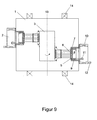
- FIG. FIG. 1 shows an arc source 2 according to the invention installed in the chamber of a vacuum treatment plant 1 provided with gas supply 4 and various power supply and pump units (not shown in more detail here), which acts on a workpiece 3.
- both magnetic systems 9, 10 are designed in the form of electromagnetic coils and arranged behind the target 6, in or on a in connection with the Target Wegplatte 8 the system against atmosphere final source insert 7.
- the first coil associated with the first magnet system 9 is located directly behind the target 6, or behind a target-water cooled in a known manner Tarruckückplatte 8.
- the second magnet system 10 associated second coil is also mounted behind the target 6, however, has a larger inner and outer diameter than the first coil 9.
- the distance between the first coil 9 and second coil 10 was set between 0 and 200 mm, in some embodiments to 67 mm. Both coils are located outside the chamber, are easily accessible and, if necessary, can be easily cooled.
- two independent DC power supplies 11, 12 are provided which provide the required for the respective process or for the respective target direct current.
- targets for example, circular blanks with a diameter of 160 mm and a thickness of 6 mm can be made of different materials such as Ti or TiAl. Greater and smaller target thicknesses and other shapes are possible as known to those skilled in the art.
- the coil geometry and an exemplary setting of the coil currents are shown in Table 1.
- the two coils are connected to the power supplies so that the currents flowing through the two coils are electrically opposite directions.
- Table 1 Kitchen sink turns ⁇ conductor [mm] I [A] R * [ ⁇ ] ⁇ inside [mm] Outside [mm] Height [mm] (1) 1000 1 1.5 12.5 150 190 60 (2) 1500 1.5 5.0 14 260 320 130 * Resistance in cold condition.
- Table 2 parameter unit Preferred area lower, upper limit print mbar 10 -4 -4x10 -1 10 -4 -10 -1 arc current A 150-210 40-250 arc voltage V 20-35 10-100 Evaporation rate g / min about 0.3 up to approx. 0.4 substrate distance mm 200-300 100-550 Be harshungs trimm. * mm 200 220
- Table 3 two exemplary modes of depositing TiN and TiAlN are additionally cited, wherein a so-called bias voltage was applied to the substrates.
- Table 3 Bias [V] Ar [sccm] N 2 [sccm] p [mbar] TiN 100 400 800 3.810 -2 TiAIN 40-150 400 800 3.810 -2
- the experiments were carried out on an RCS coating system from Balzers with an octagonal cross section and about 1000 l coating volume.
- the diameter coating chamber was 1070 mm, the height 830 mm.
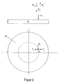
- FIG. FIG. 2 shows schematically, using the example of a circular target 6, the forces of a radially symmetrical magnetic field generated on the target surface acting on a spark.
- the spark is considered as a moving point charge Q arc .
- F is the force acting on a charge Q moving in the magnetic field
- v the velocity of the charge Q and B moving at right angles to the field lines, and the magnetic induction of the field.
- Arc directed force F ll of a radially symmetric magnetic field B ll an acceleration of the spark at right angles to the field line, ie depending on the field direction clockwise or counterclockwise.
- a magnetic field component B ⁇ - or B ⁇ + of the external magnetic field directed perpendicularly to the target surface initially does not deflect the perpendicularly entering charge carriers of the storm flux I arc , since the cross product of the vectors vx B here is zero.
- B ⁇ - and B ⁇ + generated forces F ⁇ and F ⁇ +.
- This effect can be used, as mentioned in the prior art assessment, by a two coil arrangement with a time varying current supply around the spark along a radially displaceable zero line perpendicular magnetic field component B ⁇ lead over the target surface.
- FIG. 3 As an example of a known magnetic field constructed by permanent magnets, FIG. 3 its parallel and vertical components on the target surface.
- magnets with identical orientation of the poles are mounted on the back of the target in the peripheral area surrounding one or more oppositely poled magnets in the center of the target.
- the magnets arranged similarly here have a much lower field strength in order to achieve the desired guiding effect.
- FIG. 4 shows that from FIG. FIG. 3 is a vectorial illustration of the force I arc acting at points 1-7 of the target surface on a surface which is burning perpendicularly from the plasma to the surface or deflected circularly by the parallel magnetic field.
- B causes the tangentially acting force F ⁇ , B ⁇ a normal, ie acting radially acting force F ⁇ in the target plane.
- the spark path essentially runs on a circle ring at a radial distance of 4-6 cm from the center of the target and from there periodically contracts into the center of the target. This course of the spark results because at a radial distance of 5 cm, the vertical magnetic field is zero, and the parallel field maximum.
- the spark in the central region slows down its movement over the target surface and heats it locally so strongly that target material evaporates explosively, whereupon the spark goes out.
- This also leads to an increased emission of neutral particles (splashes) and increased target removal in the middle region of the target.
- This course of the spark also proves to be unfavorable in practice, since only a relatively small part of the target surface is removed, which leads to the formation of erosion profiles and that is, frequent target changes in order to obtain the mechanical stability of the target.
- only a fraction of the often expensive target material can be vaporized before the end of the target life.
- the coil currents in accordance with Table 1 became constant at 1.5 A set.
- the magnetic field generated thereby is characterized by a profile of the vertical component which, unlike in FIG. 3, is constant over a wide range and has significantly smaller values.
- the vertical component B ⁇ here runs between +5 and -5 Gauss, whereas the vertical component in FIG. 3 between +80 and -120 gauss, with a pronounced minimum in the central area.
- parallel component B ⁇ is generally weaker than that shown in FIG.
- B ⁇ runs with a gradient of approximately 4 Gauss / cm, almost linearly close to the inflection point (corresponds to a minimum in polar coordinate representation). Only in the immediate vicinity of the curve flattens significantly.
- the formation of one or more B ⁇ zero lines in conjunction with maximum B ⁇ values is thereby deliberately avoided by a first coil whose inner diameter corresponds approximately to the target projection, whereby the spark is not forced to a preferred path and the formation of pronounced ablation profiles , such as circulating racetracks, is avoided.
- Similar magnetic fields can also be generated in a known manner by permanent magnets.
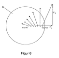
- FIG. 6 shows analogously to FIG. FIG. 4 is a vector illustration of the invention by an arc source according to the invention, as shown in FIG. 1, at positions 1-7 of the target surface to a spark acting force.
- a magnetic system designed or operated according to the invention effectively prevents the spark from damaging itself in a harmful manner toward the center of the target.
- the spark receives a relatively constant angular velocity over the entire radial range of the target, the spark thus runs the faster the farther it is from the center of the target.
- the centripetal force component F 1 acting in the middle region is smaller than that shown in FIG.
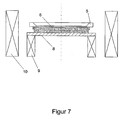
- FIG. 7 and FIG. 8 show two further embodiments of an inventive arc source, wherein in FIG. 7, the second magnet system 10 includes the first magnet system 9, while in FIG. 8, the second magnet system 10 is arranged in front of the target 6.
- the second magnet system may also have similar dimensions as the first system, in particular when the first and second systems are arranged symmetrically with respect to the target are, and the Inn trimmesser be chosen at least equal to or greater than the Ausenab distren the Targtes.
- FIG. 9 shows a vacuum treatment installation 1 with arc sources 2, which act laterally on one or more workpieces 3 moved about the installation axis 13.
- arc sources 2 which act laterally on one or more workpieces 3 moved about the installation axis 13.
- further coils 14 are provided in Helmholtz arrangement.
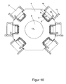
- FIG. FIG. 10 shows a coating installation 1 with 6 arculas 2 in cross-section, in which all the sources 2 are aligned essentially at right angles in the direction of the installation axis 13.
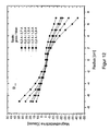
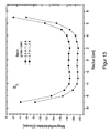
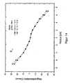
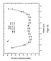
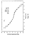
- FIG. 11 to FIG. 16 show the curves of the B ⁇ and B ⁇ components of the magnetic field at the target surface, which are generated with different setting of the coil currents.
- the arc sources were in accordance with the in FIG. 1 described operating parameters to determine optimal setting ranges and limits.
- FIG. 11 and 12 different corresponding to coil settings B ⁇ - or B ⁇ curves of the magnetic field in which a desired finely divided spark pattern could be achieved. It should be noted here that B ⁇ and B ⁇ values can not be set independently of one another for a given geometric configuration, for which reason a B ⁇ distribution in FIG. 11 only one identically labeled B ll distribution in FIG. 12 corresponds.
- FIG. 13 and 14 show a borderline case in which the arc is still finely divided, but the first signs of a periodic contraction in the middle are already visible with the naked eye. If the B ⁇ distribution is shifted much farther to negative values, a coarser spark pattern and an excessive contraction into the middle range occurs.
- FIG. 15 and 16 show another limit case.
- the spark pattern is still sufficiently finely distributed, however, the magnetic field generated in this case shows the first signs of a periodic drifting of the spark into the edge region of the target. If the B ⁇ distribution is shifted significantly further to positive values, a coarser spark occurs at the edge of the target.
- B ⁇ distribution allow for higher differences in magnetic field strength on both sides of the zero line, ie a more uneven B ⁇ distribution at the target surface, with almost uniformly finely distributed and evenly distributed spark profile, as B ⁇ distribution completely above or below the zero line.
Landscapes
- Physics & Mathematics (AREA)
- Engineering & Computer Science (AREA)
- Plasma & Fusion (AREA)
- Chemical & Material Sciences (AREA)
- Analytical Chemistry (AREA)
- Physical Vapour Deposition (AREA)
- Plasma Technology (AREA)
- Magnetic Resonance Imaging Apparatus (AREA)
- Particle Accelerators (AREA)
- Discharge Heating (AREA)
- Analysing Materials By The Use Of Radiation (AREA)
Claims (32)
- Source d'arc sous vide, comprenant une cible présentant une surface destinée à l'exploitation d'une décharge en arc, la cible étant disposée dans la région d'action d'un dispositif de génération de champ magnétique,
caractérisée en ce que
le dispositif de génération de champ magnétique est constitué d'au moins deux systèmes magnétiques de polarités opposées et est conformé de sorte que la composante du champ magnétique B┴, laquelle est perpendiculaire à la surface, a des valeurs petites sensiblement constantes inférieures à 30 Gauss, ou bien est nulle, sur une grande partie de la surface. - Source d'arc selon la revendication 1, caractérisée en ce que la valeur de la composante perpendiculaire du champ magnétique B┴ est inférieure à 20 Gauss, de préférence inférieure à 10 Gauss.
- Source d'arc selon l'une des revendications précédentes, caractérisée en ce que la plus grande partie de la surface s'étend d'une région centrale de la surface de la cible jusqu'à dans une région de bordure, c'est-à-dire de telle sorte que la plus grande partie occupe au moins 50%, notamment de préférence 60% ou plus, de la dimension ou des dimensions géométriquement déterminantes de la surface de la cible.
- Source d'arc selon l'une des revendications précédentes, caractérisée en ce que, dans la région de bordure de la surface de la cible, les valeurs B┴R de la composante perpendiculaire du champ magnétique augmentent, diminuent et/ou changent de signe par rapport aux valeurs B┴M dans la région centrale de la surface de la cible.
- Source d'arc selon l'une des revendications précédentes,
caractérisée en ce que la valeur de la composante parallèle Bll du champ magnétique est sensiblement nulle au milieu et augmente ou diminue en direction du bord de la surface de la cible, de préférence symétriquement par rapport au milieu de la cible, notamment de préférence augmente de façon sensiblement linéaire. - Source d'arc selon l'une des revendications précédentes, caractérisée en ce que le premier des deux systèmes magnétiques de polarités opposées au moins comporte au moins une première bobine électromagnétique montée derrière la cible.
- Source d'arc selon la revendication 6, caractérisée en ce que les dimensions intérieures de la première bobine coïncident avec la projection des dimensions extérieures de la surface sensiblement avec un écart de plus ou moins 30% au maximum, de préférence plus ou moins 20%.
- Source d'arc selon l'une des revendications 1 à 5, caractérisée en ce que le premier des deux systèmes magnétiques de polarités opposées au moins est constitué d'un ou plusieurs aimants permanents montés derrière la cible.
- Source d'arc selon la revendication 8, caractérisée en ce que le ou les aimants permanents possèdent eux-mêmes une faible intensité de champ ou se trouvent à une distance de la cible telle que l'intensité du champ à la surface de la cible est faible.
- Source d'arc selon l'une des revendications précédentes, caractérisée en ce que le deuxième des deux systèmes magnétiques de polarités opposées au moins comporte au moins une deuxième bobine placée coaxialement au premier système magnétique.
- Source d'arc selon la revendication 10, caractérisée en ce que la deuxième bobine est placée derrière le premier système magnétique.
- Source d'arc selon la revendication 10, caractérisée en ce que la deuxième bobine se trouve à une certaine distance en avant de la cible.
- Source d'arc selon la revendication 10, caractérisée en ce que la deuxième bobine porte le premier système magnétique disposé au moins partiellement coaxialement.
- Source d'arc selon l'une des revendications 10 à 13, caractérisée en ce que la deuxième bobine a un nombre d'enroulements et/ou un diamètre qui est supérieur à celui de la première bobine.
- Source d'arc selon l'une des revendications précédentes, caractérisée en ce que la cible est montée en cathode.
- Source d'arc selon l'une des revendications précédentes, caractérisée en ce que la cible est montée en anode.
- Installation à vide, dans laquelle est disposée au moins une source d'arc selon l'une des revendications 1 à 16.
- Installation selon la revendication 17, caractérisée en ce que la source d'arc au moins agit en direction de l'axe de l'installation et comporte au moins une autre bobine électromagnétique placée concentriquement à l'axe de l'installation afin de dévier le faisceau de plasma généré.
- Installation selon la revendication 18, caractérisée en ce que l'autre bobine au moins est raccordée à au moins une source de courant variable dans le temps dotée d'une unité de commande afin de dévier de façon variable l'orientation du faisceau de plasma généré par la source d'arc au moins.
- Installation selon l'une des revendications 18 à 19, caractérisée en ce que au moins deux autres bobines électromagnétiques sont disposées concentriquement à l'axe de l'installation, de préférence dans la région supérieure ainsi que dans la région inférieure respectivement dans les régions correspondantes latéralement adjacentes de l'installation, qui ont un diamètre identique ou différent respectivement une structure correspondant sensiblement à un agencement de bobine de Helmholz.
- Procédé d'exploitation d'une décharge en arc à la surface d'une cible d'une source d'arc à l'aide d'un dispositif générateur de champ magnétique, caractérisé en ce qu'un champ magnétique est généré à la surface avec le dispositif générateur de champ magnétique constitué d'au moins deux systèmes magnétiques de polarités opposées de telle sorte que, sur une grande partie de la surface, sa composante perpendiculaire B⊥ est nulle ou a une valeur faible sensiblement constante inférieure 30 Gauss.
- Procédé selon la revendication 21, caractérisée en ce que la valeur de la composante perpendiculaire du champ magnétique est réglée de façon à être inférieure à 30 Gauss, de préférence inférieure à 20 Gauss, notamment de façon préférée inférieure à 10 Gauss.
- Procédé selon l'une des revendications 21 à 22, caractérisée en ce que le champ magnétique est réglé de sorte que la plus grande partie de la surface s'étend d'une région médiane de la surface de la cible à une région de bordure avec une composante perpendiculaire B⊥ sensiblement constante proche de zéro, c'est-à-dire que la région centrale occupe au moins 50%, notamment de préférence 60% ou plus, de la dimension ou des dimensions géométriquement déterminantes de la surface de la cible.
- Procédé selon l'une des revendications 21 à 23, caractérisée en ce que les valeurs B⊥R de la composante perpendiculaire du champ magnétique sont réglées de façon à augmenter, diminuer et/ou changer de signe par rapport aux valeurs B┴M dans la région centrale de la surface de la cible.
- Procédé selon l'une des revendications 21 à 24, caractérisé en ce que la valeur de la composante parallèle Bll du champ magnétique est réglée de façon à être nulle au centre et à augmenter en direction du bord de la surface de la cible, de préférence à augmenter symétriquement par rapport au centre de la cible, de sorte que la force agissant dans le sens horaires ou dans le sens antihoraire, tangentiellement au rayonnement électromagnétique, augmente en direction du bord de la cible.
- Procédé selon l'une des revendications 21 à 24, caractérisé en ce qu'un champ magnétique lointain, orienté sensiblement perpendiculairement à la surface, est généré en plus dans une région située devant la cible.
- Procédé selon l'une des revendications 21 à 26, caractérisé en ce que l'intensité du champ magnétique est réglée de façon à correspondre au matériau de la cible et/ou à l'épaisseur de la cible.
- Procédé selon l'une des revendications 21 à 27, caractérisé en ce que le dispositif générateur de champ magnétique comporte au moins une bobine placée derrière la cible et en ce qu'une source de tension est appliquée à la bobine au moins pour régler le champ magnétique de façon à ce qu'un courant circule dans un premier sens.
- Procédé selon l'une des revendications 21 à 27, caractérisé en ce que le dispositif générateur de champ magnétique comporte au moins un système magnétique placé derrière la cible et constitué d'un ou plusieurs aimants permanents.
- Procédé selon l'une des revendications 28 à 29, caractérisé en ce qu' une deuxième bobine au moins est placée derrière la cible, devant la cible, ou en entourant la cible et en ce qu'une tension est appliquée à la deuxième bobine afin de régler le champ magnétique de façon à générer un deuxième champ magnétique opposé au champ magnétique généré par le premier système magnétique.
- Procédé de revêtement d'une pièce, notamment d'un outil et/ou d'un composant en utilisant l'un des procédés selon les revendications 20 à 29.
- Procédé de revêtement d'une pièce, notamment d'un outil et/ou d'un composant en utilisant une source d'arc selon les revendications 1 à 16.
Applications Claiming Priority (3)
| Application Number | Priority Date | Filing Date | Title |
|---|---|---|---|
| CH216302 | 2002-12-19 | ||
| CH21632002 | 2002-12-19 | ||
| PCT/CH2003/000710 WO2004057642A2 (fr) | 2002-12-19 | 2003-10-30 | Source d'arc sous vide comprenant un dispositif de production de champ magnetique |
Publications (3)
| Publication Number | Publication Date |
|---|---|
| EP1576641A2 EP1576641A2 (fr) | 2005-09-21 |
| EP1576641B1 true EP1576641B1 (fr) | 2007-09-05 |
| EP1576641B8 EP1576641B8 (fr) | 2007-10-17 |
Family
ID=32661016
Family Applications (1)
| Application Number | Title | Priority Date | Filing Date |
|---|---|---|---|
| EP03753214A Expired - Lifetime EP1576641B8 (fr) | 2002-12-19 | 2003-10-30 | Source d'arc sous vide comprenant un dispositif de production de champ magnetique |
Country Status (11)
| Country | Link |
|---|---|
| US (1) | US20060175190A1 (fr) |
| EP (1) | EP1576641B8 (fr) |
| JP (1) | JP4989026B2 (fr) |
| KR (1) | KR101074554B1 (fr) |
| CN (1) | CN100573802C (fr) |
| AT (1) | ATE372586T1 (fr) |
| AU (1) | AU2003271505A1 (fr) |
| BR (1) | BR0317372A (fr) |
| DE (1) | DE50308139D1 (fr) |
| MX (1) | MXPA05006762A (fr) |
| WO (1) | WO2004057642A2 (fr) |
Families Citing this family (16)
| Publication number | Priority date | Publication date | Assignee | Title |
|---|---|---|---|---|
| DE102005040536A1 (de) * | 2005-08-26 | 2007-03-29 | Honeywell Technologies Sarl | Verfahren und Vorrichtung zum Messen einer Kraft und einer Position |
| KR100727646B1 (ko) * | 2005-12-06 | 2007-06-13 | 장희선 | 이온 플레이팅장치의 금속타겟용 자속유도구 |
| EP2466614A3 (fr) * | 2006-05-16 | 2013-05-22 | Oerlikon Trading AG, Trübbach | Source d'arc et agencement d'aimant |
| US7857948B2 (en) * | 2006-07-19 | 2010-12-28 | Oerlikon Trading Ag, Trubbach | Method for manufacturing poorly conductive layers |
| TWI411696B (zh) | 2006-07-19 | 2013-10-11 | Oerlikon Trading Ag | 沉積電絕緣層之方法 |
| US7939181B2 (en) * | 2006-10-11 | 2011-05-10 | Oerlikon Trading Ag, Trubbach | Layer system with at least one mixed crystal layer of a multi-oxide |
| ES2575119T3 (es) * | 2007-04-17 | 2016-06-24 | Oerlikon Surface Solutions Ag, Pfäffikon | Fuente de evaporación en vacío de arco voltaico, así como una cámara de evaporación en vacío de arco voltaico con una fuente de evaporación en vacío de arco voltaico |
| US20110315544A1 (en) * | 2008-12-26 | 2011-12-29 | Fundacion Tekniker | Arc evaporator and method for operating the evaporator |
| DE102009008161A1 (de) | 2009-02-09 | 2010-08-12 | Oerlikon Trading Ag, Trübbach | Modifizierbare Magnetkonfiguration für Arc-Verdampfungsquellen |
| JP5649308B2 (ja) * | 2009-04-28 | 2015-01-07 | 株式会社神戸製鋼所 | 成膜速度が速いアーク式蒸発源及びこのアーク式蒸発源を用いた皮膜の製造方法 |
| WO2011131460A2 (fr) * | 2010-04-23 | 2011-10-27 | Sulzer Metaplas Gmbh | Revêtement déposé par dépôt physique en phase vapeur (pvd) pour l'usinage de métaux |
| JP5318052B2 (ja) * | 2010-06-23 | 2013-10-16 | 株式会社神戸製鋼所 | 成膜速度が速いアーク式蒸発源、このアーク式蒸発源を用いた皮膜の製造方法及び成膜装置 |
| JP6403269B2 (ja) * | 2014-07-30 | 2018-10-10 | 株式会社神戸製鋼所 | アーク蒸発源 |
| EP3938557B1 (fr) * | 2019-03-15 | 2023-09-06 | Nanofilm Technologies International Limited | Source d'arc cathodique améliorée |
| KR102156499B1 (ko) | 2019-05-31 | 2020-09-15 | 배상열 | 아크 발생 장치 |
| SK500322019A3 (sk) | 2019-07-11 | 2021-01-13 | STATON, s. r. o. | Zdroj plazmy využívajúci katódový vákuový oblúk s vylepšenou konfiguráciou magnetického poľa a spôsob jeho činnosti |
Family Cites Families (20)
| Publication number | Priority date | Publication date | Assignee | Title |
|---|---|---|---|---|
| US4444635A (en) * | 1981-07-22 | 1984-04-24 | Hitachi, Ltd. | Film forming method |
| US4673477A (en) * | 1984-03-02 | 1987-06-16 | Regents Of The University Of Minnesota | Controlled vacuum arc material deposition, method and apparatus |
| JPS6247477A (ja) * | 1985-08-28 | 1987-03-02 | Tokuda Seisakusho Ltd | スパツタリング装置 |
| NL8700620A (nl) * | 1987-03-16 | 1988-10-17 | Hauzer Holding | Kathode boogverdampingsinrichting alsmede werkwijze voor het bedrijven daarvan. |
| DE4017111C2 (de) * | 1990-05-28 | 1998-01-29 | Hauzer Holding | Lichtbogen-Magnetron-Vorrichtung |
| US5298136A (en) | 1987-08-18 | 1994-03-29 | Regents Of The University Of Minnesota | Steered arc coating with thick targets |
| US5234560A (en) * | 1989-08-14 | 1993-08-10 | Hauzer Holdings Bv | Method and device for sputtering of films |
| CN1029568C (zh) * | 1991-06-01 | 1995-08-23 | 中国科学院电工研究所 | 大电流多弧斑受控真空电弧蒸发源 |
| DE19617057C2 (de) * | 1996-04-29 | 1998-07-23 | Ardenne Anlagentech Gmbh | Sputteranlage mit zwei längserstreckten Magnetrons |
| US6036828A (en) * | 1997-08-30 | 2000-03-14 | United Technologies Corporation | Apparatus for steering the arc in a cathodic arc coater |
| US6103074A (en) * | 1998-02-14 | 2000-08-15 | Phygen, Inc. | Cathode arc vapor deposition method and apparatus |
| WO2000016373A1 (fr) * | 1998-09-14 | 2000-03-23 | Unaxis Trading Ag | Ensemble cible pour chambre d'evaporation par l'intermediaire d'un arc |
| TWI242049B (en) * | 1999-01-14 | 2005-10-21 | Kobe Steel Ltd | Vacuum arc evaporation source and vacuum arc vapor deposition apparatus |
| JP3789667B2 (ja) * | 1999-01-14 | 2006-06-28 | 株式会社神戸製鋼所 | 真空アーク蒸発源及び真空アーク蒸着装置 |
| US6254745B1 (en) * | 1999-02-19 | 2001-07-03 | Tokyo Electron Limited | Ionized physical vapor deposition method and apparatus with magnetic bucket and concentric plasma and material source |
| US5997705A (en) * | 1999-04-14 | 1999-12-07 | Vapor Technologies, Inc. | Rectangular filtered arc plasma source |
| JP3917348B2 (ja) * | 1999-05-26 | 2007-05-23 | 株式会社神戸製鋼所 | アーク蒸発源、真空蒸着装置及び真空蒸着方法 |
| JP3993388B2 (ja) * | 2001-01-16 | 2007-10-17 | 株式会社神戸製鋼所 | 真空アーク蒸発源 |
| JP2004523658A (ja) * | 2001-03-27 | 2004-08-05 | フンダシオン テクニケル | 大きい表面領域を有するターゲットのための強力な磁気ガイドを伴うアーク蒸着装置 |
| DE10127013A1 (de) * | 2001-06-05 | 2002-12-12 | Gabriel Herbert M | Lichtbogen-Verdampfungsvorrichtung |
-
2003
- 2003-10-30 BR BR0317372-0A patent/BR0317372A/pt not_active IP Right Cessation
- 2003-10-30 MX MXPA05006762A patent/MXPA05006762A/es active IP Right Grant
- 2003-10-30 JP JP2004560974A patent/JP4989026B2/ja not_active Expired - Fee Related
- 2003-10-30 AT AT03753214T patent/ATE372586T1/de not_active IP Right Cessation
- 2003-10-30 EP EP03753214A patent/EP1576641B8/fr not_active Expired - Lifetime
- 2003-10-30 KR KR1020057011359A patent/KR101074554B1/ko not_active Expired - Fee Related
- 2003-10-30 DE DE50308139T patent/DE50308139D1/de not_active Expired - Lifetime
- 2003-10-30 US US10/540,162 patent/US20060175190A1/en not_active Abandoned
- 2003-10-30 CN CNB200380107068XA patent/CN100573802C/zh not_active Expired - Fee Related
- 2003-10-30 AU AU2003271505A patent/AU2003271505A1/en not_active Abandoned
- 2003-10-30 WO PCT/CH2003/000710 patent/WO2004057642A2/fr not_active Ceased
Non-Patent Citations (1)
| Title |
|---|
| None * |
Also Published As
| Publication number | Publication date |
|---|---|
| DE50308139D1 (de) | 2007-10-18 |
| AU2003271505A1 (en) | 2004-07-14 |
| US20060175190A1 (en) | 2006-08-10 |
| AU2003271505A8 (en) | 2004-07-14 |
| KR20050084412A (ko) | 2005-08-26 |
| JP2006510803A (ja) | 2006-03-30 |
| EP1576641A2 (fr) | 2005-09-21 |
| JP4989026B2 (ja) | 2012-08-01 |
| BR0317372A (pt) | 2005-11-16 |
| EP1576641B8 (fr) | 2007-10-17 |
| WO2004057642A2 (fr) | 2004-07-08 |
| WO2004057642A3 (fr) | 2004-12-09 |
| CN100573802C (zh) | 2009-12-23 |
| MXPA05006762A (es) | 2005-09-08 |
| CN1729549A (zh) | 2006-02-01 |
| KR101074554B1 (ko) | 2011-10-17 |
| ATE372586T1 (de) | 2007-09-15 |
Similar Documents
| Publication | Publication Date | Title |
|---|---|---|
| EP1576641B1 (fr) | Source d'arc sous vide comprenant un dispositif de production de champ magnetique | |
| EP2720249B1 (fr) | Chambre de vaporisation d'arcs électriques dotée d'une source de vaporisation d'arcs électriques sous vide | |
| DE19755159C2 (de) | Dünnfilmbeschichtungseinrichtung unter Verwendung einer Kathoden-Bogenentladung | |
| EP2018653B1 (fr) | Source d'arc et arrangement d'aimants | |
| DE69206028T2 (de) | Vorrichtung und Verfahren zur Beschichtung eines Substrates unter Verwendung der Vakuum-Bogen-Verdampfung. | |
| EP2041331B1 (fr) | Procédé pour le dépôt de couches électriquement isolantes | |
| EP0946966B1 (fr) | Dispositif de pulverisation cathodique | |
| DE10084452B3 (de) | Lichtbogenquelle mit rechteckiger Kathode und Verfahren zur Lenkung eines Lichtbogenflecks | |
| EP0339554A2 (fr) | Source de faisceau ionique à haute fréquence | |
| DE69421157T2 (de) | Plasmastrahl-Erzeugungsverfahren und Vorrichtung die einen Hochleistungsplasmastrahl erzeugen Kann | |
| EP2778253B1 (fr) | Source d'évaporation cylindrique | |
| EP2159821A2 (fr) | Dispositif de revêtement destiné au revêtement d'un substrat et procédé de revêtement d'un substrat | |
| DE69515626T2 (de) | Plasmabehandlungsverfahren und -vorrichtung | |
| DE1515295B1 (de) | Vorrichtung zum Aufbringen dünner Schichten aus dem Material einer Zerstäubungskathode auf eine senkrecht zu einer Anode angeordnete Unterlage | |
| EP0811238B1 (fr) | Dispositif de pulverisation reactive | |
| DE10127013A1 (de) | Lichtbogen-Verdampfungsvorrichtung | |
| DE10250941B4 (de) | Quelle für Vakuumbehandlungsprozess sowie Verfahren zum Betreiben einer solchen | |
| EP1036207A2 (fr) | Dispositif de traitement de pieces dans un plasma basse pression | |
| DE3411536A1 (de) | Magnetronkatode fuer katodenzerstaeubungsanlagen | |
| DE10010448C1 (de) | Kathode | |
| DE10234858A1 (de) | Einrichtung zur Erzeugung einer Magnetron-Entladung | |
| CH702969A2 (de) | Segmentierte Anode. | |
| EP3583619B1 (fr) | Évaporation par arc cathodique avec enlèvement de matière à la cathode prédéfini | |
| EP1473382A1 (fr) | Procédé et dispositif de déposition d'une couche activée par plasma par pulvérisation magnétron | |
| DE102012106403A1 (de) | Reaktives Magnetronsputtern zur Beschichtung von Substraten und Vorrichtung zur Ausführung des Verfahrens |
Legal Events
| Date | Code | Title | Description |
|---|---|---|---|
| PUAI | Public reference made under article 153(3) epc to a published international application that has entered the european phase |
Free format text: ORIGINAL CODE: 0009012 |
|
| 17P | Request for examination filed |
Effective date: 20050719 |
|
| AK | Designated contracting states |
Kind code of ref document: A2 Designated state(s): AT BE BG CH CY CZ DE DK EE ES FI FR GB GR HU IE IT LI LU MC NL PT RO SE SI SK TR |
|
| AX | Request for extension of the european patent |
Extension state: AL LT LV MK |
|
| DAX | Request for extension of the european patent (deleted) | ||
| RIN1 | Information on inventor provided before grant (corrected) |
Inventor name: WOHLRAB, CHRISTIAN Inventor name: SCHUETZE, ANDREAS |
|
| RAP1 | Party data changed (applicant data changed or rights of an application transferred) |
Owner name: OC OERLIKON BALZERS AG |
|
| GRAP | Despatch of communication of intention to grant a patent |
Free format text: ORIGINAL CODE: EPIDOSNIGR1 |
|
| GRAS | Grant fee paid |
Free format text: ORIGINAL CODE: EPIDOSNIGR3 |
|
| GRAA | (expected) grant |
Free format text: ORIGINAL CODE: 0009210 |
|
| AK | Designated contracting states |
Kind code of ref document: B1 Designated state(s): AT BE BG CH CY CZ DE DK EE ES FI FR GB GR HU IE IT LI LU MC NL PT RO SE SI SK TR |
|
| REG | Reference to a national code |
Ref country code: GB Ref legal event code: FG4D Free format text: NOT ENGLISH |
|
| REG | Reference to a national code |
Ref country code: CH Ref legal event code: EP |
|
| RAP2 | Party data changed (patent owner data changed or rights of a patent transferred) |
Owner name: OERLIKON TRADING AG, TRUEBBACH |
|
| REF | Corresponds to: |
Ref document number: 50308139 Country of ref document: DE Date of ref document: 20071018 Kind code of ref document: P |
|
| GBT | Gb: translation of ep patent filed (gb section 77(6)(a)/1977) |
Effective date: 20071003 |
|
| REG | Reference to a national code |
Ref country code: IE Ref legal event code: FG4D Free format text: LANGUAGE OF EP DOCUMENT: GERMAN |
|
| NLT2 | Nl: modifications (of names), taken from the european patent patent bulletin |
Owner name: OERLIKON TRADING AG, TRUEBBACH Effective date: 20071003 |
|
| ET | Fr: translation filed | ||
| REG | Reference to a national code |
Ref country code: SE Ref legal event code: TRGR |
|
| PG25 | Lapsed in a contracting state [announced via postgrant information from national office to epo] |
Ref country code: FI Free format text: LAPSE BECAUSE OF FAILURE TO SUBMIT A TRANSLATION OF THE DESCRIPTION OR TO PAY THE FEE WITHIN THE PRESCRIBED TIME-LIMIT Effective date: 20070905 Ref country code: ES Free format text: LAPSE BECAUSE OF FAILURE TO SUBMIT A TRANSLATION OF THE DESCRIPTION OR TO PAY THE FEE WITHIN THE PRESCRIBED TIME-LIMIT Effective date: 20071216 |
|
| NLV1 | Nl: lapsed or annulled due to failure to fulfill the requirements of art. 29p and 29m of the patents act | ||
| REG | Reference to a national code |
Ref country code: IE Ref legal event code: FD4D |
|
| BERE | Be: lapsed |
Owner name: OERLIKON TRADING AG Effective date: 20071031 |
|
| PG25 | Lapsed in a contracting state [announced via postgrant information from national office to epo] |
Ref country code: NL Free format text: LAPSE BECAUSE OF FAILURE TO SUBMIT A TRANSLATION OF THE DESCRIPTION OR TO PAY THE FEE WITHIN THE PRESCRIBED TIME-LIMIT Effective date: 20070905 Ref country code: GR Free format text: LAPSE BECAUSE OF FAILURE TO SUBMIT A TRANSLATION OF THE DESCRIPTION OR TO PAY THE FEE WITHIN THE PRESCRIBED TIME-LIMIT Effective date: 20071206 |
|
| PG25 | Lapsed in a contracting state [announced via postgrant information from national office to epo] |
Ref country code: PT Free format text: LAPSE BECAUSE OF FAILURE TO SUBMIT A TRANSLATION OF THE DESCRIPTION OR TO PAY THE FEE WITHIN THE PRESCRIBED TIME-LIMIT Effective date: 20080206 Ref country code: MC Free format text: LAPSE BECAUSE OF NON-PAYMENT OF DUE FEES Effective date: 20071031 Ref country code: IE Free format text: LAPSE BECAUSE OF FAILURE TO SUBMIT A TRANSLATION OF THE DESCRIPTION OR TO PAY THE FEE WITHIN THE PRESCRIBED TIME-LIMIT Effective date: 20070905 Ref country code: CZ Free format text: LAPSE BECAUSE OF FAILURE TO SUBMIT A TRANSLATION OF THE DESCRIPTION OR TO PAY THE FEE WITHIN THE PRESCRIBED TIME-LIMIT Effective date: 20070905 Ref country code: SK Free format text: LAPSE BECAUSE OF FAILURE TO SUBMIT A TRANSLATION OF THE DESCRIPTION OR TO PAY THE FEE WITHIN THE PRESCRIBED TIME-LIMIT Effective date: 20070905 |
|
| PG25 | Lapsed in a contracting state [announced via postgrant information from national office to epo] |
Ref country code: RO Free format text: LAPSE BECAUSE OF FAILURE TO SUBMIT A TRANSLATION OF THE DESCRIPTION OR TO PAY THE FEE WITHIN THE PRESCRIBED TIME-LIMIT Effective date: 20070905 |
|
| PLBE | No opposition filed within time limit |
Free format text: ORIGINAL CODE: 0009261 |
|
| STAA | Information on the status of an ep patent application or granted ep patent |
Free format text: STATUS: NO OPPOSITION FILED WITHIN TIME LIMIT |
|
| PG25 | Lapsed in a contracting state [announced via postgrant information from national office to epo] |
Ref country code: DK Free format text: LAPSE BECAUSE OF FAILURE TO SUBMIT A TRANSLATION OF THE DESCRIPTION OR TO PAY THE FEE WITHIN THE PRESCRIBED TIME-LIMIT Effective date: 20070905 |
|
| 26N | No opposition filed |
Effective date: 20080606 |
|
| PG25 | Lapsed in a contracting state [announced via postgrant information from national office to epo] |
Ref country code: BE Free format text: LAPSE BECAUSE OF NON-PAYMENT OF DUE FEES Effective date: 20071031 |
|
| PG25 | Lapsed in a contracting state [announced via postgrant information from national office to epo] |
Ref country code: EE Free format text: LAPSE BECAUSE OF FAILURE TO SUBMIT A TRANSLATION OF THE DESCRIPTION OR TO PAY THE FEE WITHIN THE PRESCRIBED TIME-LIMIT Effective date: 20070905 |
|
| PG25 | Lapsed in a contracting state [announced via postgrant information from national office to epo] |
Ref country code: AT Free format text: LAPSE BECAUSE OF NON-PAYMENT OF DUE FEES Effective date: 20071030 |
|
| PG25 | Lapsed in a contracting state [announced via postgrant information from national office to epo] |
Ref country code: SI Free format text: LAPSE BECAUSE OF FAILURE TO SUBMIT A TRANSLATION OF THE DESCRIPTION OR TO PAY THE FEE WITHIN THE PRESCRIBED TIME-LIMIT Effective date: 20070905 |
|
| PG25 | Lapsed in a contracting state [announced via postgrant information from national office to epo] |
Ref country code: CY Free format text: LAPSE BECAUSE OF FAILURE TO SUBMIT A TRANSLATION OF THE DESCRIPTION OR TO PAY THE FEE WITHIN THE PRESCRIBED TIME-LIMIT Effective date: 20070905 |
|
| PG25 | Lapsed in a contracting state [announced via postgrant information from national office to epo] |
Ref country code: LU Free format text: LAPSE BECAUSE OF NON-PAYMENT OF DUE FEES Effective date: 20071030 Ref country code: BG Free format text: LAPSE BECAUSE OF FAILURE TO SUBMIT A TRANSLATION OF THE DESCRIPTION OR TO PAY THE FEE WITHIN THE PRESCRIBED TIME-LIMIT Effective date: 20071205 |
|
| PG25 | Lapsed in a contracting state [announced via postgrant information from national office to epo] |
Ref country code: TR Free format text: LAPSE BECAUSE OF FAILURE TO SUBMIT A TRANSLATION OF THE DESCRIPTION OR TO PAY THE FEE WITHIN THE PRESCRIBED TIME-LIMIT Effective date: 20070905 Ref country code: HU Free format text: LAPSE BECAUSE OF FAILURE TO SUBMIT A TRANSLATION OF THE DESCRIPTION OR TO PAY THE FEE WITHIN THE PRESCRIBED TIME-LIMIT Effective date: 20080306 |
|
| PG25 | Lapsed in a contracting state [announced via postgrant information from national office to epo] |
Ref country code: IT Free format text: LAPSE BECAUSE OF NON-PAYMENT OF DUE FEES Effective date: 20071031 |
|
| REG | Reference to a national code |
Ref country code: FR Ref legal event code: PLFP Year of fee payment: 13 |
|
| REG | Reference to a national code |
Ref country code: FR Ref legal event code: TP Owner name: OERLIKON SURFACE SOLUTIONS AG, TRUBBACH, CH Effective date: 20151130 |
|
| REG | Reference to a national code |
Ref country code: FR Ref legal event code: PLFP Year of fee payment: 14 |
|
| REG | Reference to a national code |
Ref country code: FR Ref legal event code: PLFP Year of fee payment: 15 |
|
| REG | Reference to a national code |
Ref country code: FR Ref legal event code: PLFP Year of fee payment: 16 |
|
| PGFP | Annual fee paid to national office [announced via postgrant information from national office to epo] |
Ref country code: GB Payment date: 20211026 Year of fee payment: 19 Ref country code: SE Payment date: 20211022 Year of fee payment: 19 |
|
| PGFP | Annual fee paid to national office [announced via postgrant information from national office to epo] |
Ref country code: FR Payment date: 20211028 Year of fee payment: 19 Ref country code: CH Payment date: 20211022 Year of fee payment: 19 |
|
| PGFP | Annual fee paid to national office [announced via postgrant information from national office to epo] |
Ref country code: DE Payment date: 20211228 Year of fee payment: 19 |
|
| REG | Reference to a national code |
Ref country code: DE Ref legal event code: R119 Ref document number: 50308139 Country of ref document: DE |
|
| REG | Reference to a national code |
Ref country code: SE Ref legal event code: EUG |
|
| REG | Reference to a national code |
Ref country code: CH Ref legal event code: PL |
|
| GBPC | Gb: european patent ceased through non-payment of renewal fee |
Effective date: 20221030 |
|
| PG25 | Lapsed in a contracting state [announced via postgrant information from national office to epo] |
Ref country code: LI Free format text: LAPSE BECAUSE OF NON-PAYMENT OF DUE FEES Effective date: 20221031 Ref country code: FR Free format text: LAPSE BECAUSE OF NON-PAYMENT OF DUE FEES Effective date: 20221031 Ref country code: DE Free format text: LAPSE BECAUSE OF NON-PAYMENT OF DUE FEES Effective date: 20230503 Ref country code: CH Free format text: LAPSE BECAUSE OF NON-PAYMENT OF DUE FEES Effective date: 20221031 |
|
| PG25 | Lapsed in a contracting state [announced via postgrant information from national office to epo] |
Ref country code: SE Free format text: LAPSE BECAUSE OF NON-PAYMENT OF DUE FEES Effective date: 20221031 |
|
| PG25 | Lapsed in a contracting state [announced via postgrant information from national office to epo] |
Ref country code: GB Free format text: LAPSE BECAUSE OF NON-PAYMENT OF DUE FEES Effective date: 20221030 |