EP2678570B1 - Hydraulische einrichtung zur betätigung einer kupplung - Google Patents
Hydraulische einrichtung zur betätigung einer kupplung Download PDFInfo
- Publication number
- EP2678570B1 EP2678570B1 EP12718564.3A EP12718564A EP2678570B1 EP 2678570 B1 EP2678570 B1 EP 2678570B1 EP 12718564 A EP12718564 A EP 12718564A EP 2678570 B1 EP2678570 B1 EP 2678570B1
- Authority
- EP
- European Patent Office
- Prior art keywords
- pump
- working cylinder
- hydraulic
- hydraulic device
- electric motor
- Prior art date
- Legal status (The legal status is an assumption and is not a legal conclusion. Google has not performed a legal analysis and makes no representation as to the accuracy of the status listed.)
- Revoked
Links
Images


Classifications
-
- F—MECHANICAL ENGINEERING; LIGHTING; HEATING; WEAPONS; BLASTING
- F16—ENGINEERING ELEMENTS AND UNITS; GENERAL MEASURES FOR PRODUCING AND MAINTAINING EFFECTIVE FUNCTIONING OF MACHINES OR INSTALLATIONS; THERMAL INSULATION IN GENERAL
- F16D—COUPLINGS FOR TRANSMITTING ROTATION; CLUTCHES; BRAKES
- F16D25/00—Fluid-actuated clutches
- F16D25/12—Details not specific to one of the before-mentioned types
-
- F—MECHANICAL ENGINEERING; LIGHTING; HEATING; WEAPONS; BLASTING
- F16—ENGINEERING ELEMENTS AND UNITS; GENERAL MEASURES FOR PRODUCING AND MAINTAINING EFFECTIVE FUNCTIONING OF MACHINES OR INSTALLATIONS; THERMAL INSULATION IN GENERAL
- F16D—COUPLINGS FOR TRANSMITTING ROTATION; CLUTCHES; BRAKES
- F16D47/00—Systems of clutches, or clutches and couplings, comprising devices of types grouped under at least two of the following sets of groups: F16D1/00 - F16D9/00, F16D11/00 - F16D23/00, F16D25/00 - F16D29/00, F16D31/00 - F16D39/00, F16D41/00 - F16D45/00
- F16D47/06—Systems of clutches, or clutches and couplings, comprising devices of types grouped under at least two of the following sets of groups: F16D1/00 - F16D9/00, F16D11/00 - F16D23/00, F16D25/00 - F16D29/00, F16D31/00 - F16D39/00, F16D41/00 - F16D45/00 of which at least one is a clutch with a fluid or a semifluid as power-transmitting means
-
- F—MECHANICAL ENGINEERING; LIGHTING; HEATING; WEAPONS; BLASTING
- F15—FLUID-PRESSURE ACTUATORS; HYDRAULICS OR PNEUMATICS IN GENERAL
- F15B—SYSTEMS ACTING BY MEANS OF FLUIDS IN GENERAL; FLUID-PRESSURE ACTUATORS, e.g. SERVOMOTORS; DETAILS OF FLUID-PRESSURE SYSTEMS, NOT OTHERWISE PROVIDED FOR
- F15B15/00—Fluid-actuated devices for displacing a member from one position to another; Gearing associated therewith
- F15B15/18—Combined units comprising both motor and pump
-
- F—MECHANICAL ENGINEERING; LIGHTING; HEATING; WEAPONS; BLASTING
- F15—FLUID-PRESSURE ACTUATORS; HYDRAULICS OR PNEUMATICS IN GENERAL
- F15B—SYSTEMS ACTING BY MEANS OF FLUIDS IN GENERAL; FLUID-PRESSURE ACTUATORS, e.g. SERVOMOTORS; DETAILS OF FLUID-PRESSURE SYSTEMS, NOT OTHERWISE PROVIDED FOR
- F15B7/00—Systems in which the movement produced is definitely related to the output of a volumetric pump; Telemotors
- F15B7/005—With rotary or crank input
- F15B7/006—Rotary pump input
-
- F—MECHANICAL ENGINEERING; LIGHTING; HEATING; WEAPONS; BLASTING
- F16—ENGINEERING ELEMENTS AND UNITS; GENERAL MEASURES FOR PRODUCING AND MAINTAINING EFFECTIVE FUNCTIONING OF MACHINES OR INSTALLATIONS; THERMAL INSULATION IN GENERAL
- F16D—COUPLINGS FOR TRANSMITTING ROTATION; CLUTCHES; BRAKES
- F16D48/00—External control of clutches
- F16D48/02—Control by fluid pressure
-
- H—ELECTRICITY
- H02—GENERATION; CONVERSION OR DISTRIBUTION OF ELECTRIC POWER
- H02K—DYNAMO-ELECTRIC MACHINES
- H02K11/00—Structural association of dynamo-electric machines with electric components or with devices for shielding, monitoring or protection
- H02K11/30—Structural association with control circuits or drive circuits
- H02K11/38—Control circuits or drive circuits associated with geared commutator motors of the worm-and-wheel type
-
- H—ELECTRICITY
- H02—GENERATION; CONVERSION OR DISTRIBUTION OF ELECTRIC POWER
- H02K—DYNAMO-ELECTRIC MACHINES
- H02K5/00—Casings; Enclosures; Supports
- H02K5/04—Casings or enclosures characterised by the shape, form or construction thereof
- H02K5/10—Casings or enclosures characterised by the shape, form or construction thereof with arrangements for protection from ingress, e.g. water or fingers
-
- H—ELECTRICITY
- H02—GENERATION; CONVERSION OR DISTRIBUTION OF ELECTRIC POWER
- H02K—DYNAMO-ELECTRIC MACHINES
- H02K7/00—Arrangements for handling mechanical energy structurally associated with dynamo-electric machines, e.g. structural association with mechanical driving motors or auxiliary dynamo-electric machines
- H02K7/06—Means for converting reciprocating motion into rotary motion or vice versa
-
- F—MECHANICAL ENGINEERING; LIGHTING; HEATING; WEAPONS; BLASTING
- F15—FLUID-PRESSURE ACTUATORS; HYDRAULICS OR PNEUMATICS IN GENERAL
- F15B—SYSTEMS ACTING BY MEANS OF FLUIDS IN GENERAL; FLUID-PRESSURE ACTUATORS, e.g. SERVOMOTORS; DETAILS OF FLUID-PRESSURE SYSTEMS, NOT OTHERWISE PROVIDED FOR
- F15B2211/00—Circuits for servomotor systems
- F15B2211/20—Fluid pressure source, e.g. accumulator or variable axial piston pump
- F15B2211/205—Systems with pumps
- F15B2211/2053—Type of pump
- F15B2211/20546—Type of pump variable capacity
-
- F—MECHANICAL ENGINEERING; LIGHTING; HEATING; WEAPONS; BLASTING
- F15—FLUID-PRESSURE ACTUATORS; HYDRAULICS OR PNEUMATICS IN GENERAL
- F15B—SYSTEMS ACTING BY MEANS OF FLUIDS IN GENERAL; FLUID-PRESSURE ACTUATORS, e.g. SERVOMOTORS; DETAILS OF FLUID-PRESSURE SYSTEMS, NOT OTHERWISE PROVIDED FOR
- F15B2211/00—Circuits for servomotor systems
- F15B2211/20—Fluid pressure source, e.g. accumulator or variable axial piston pump
- F15B2211/25—Pressure control functions
- F15B2211/251—High pressure control
-
- F—MECHANICAL ENGINEERING; LIGHTING; HEATING; WEAPONS; BLASTING
- F15—FLUID-PRESSURE ACTUATORS; HYDRAULICS OR PNEUMATICS IN GENERAL
- F15B—SYSTEMS ACTING BY MEANS OF FLUIDS IN GENERAL; FLUID-PRESSURE ACTUATORS, e.g. SERVOMOTORS; DETAILS OF FLUID-PRESSURE SYSTEMS, NOT OTHERWISE PROVIDED FOR
- F15B2211/00—Circuits for servomotor systems
- F15B2211/60—Circuit components or control therefor
- F15B2211/63—Electronic controllers
- F15B2211/6303—Electronic controllers using input signals
- F15B2211/6306—Electronic controllers using input signals representing a pressure
- F15B2211/6313—Electronic controllers using input signals representing a pressure the pressure being a load pressure
-
- F—MECHANICAL ENGINEERING; LIGHTING; HEATING; WEAPONS; BLASTING
- F15—FLUID-PRESSURE ACTUATORS; HYDRAULICS OR PNEUMATICS IN GENERAL
- F15B—SYSTEMS ACTING BY MEANS OF FLUIDS IN GENERAL; FLUID-PRESSURE ACTUATORS, e.g. SERVOMOTORS; DETAILS OF FLUID-PRESSURE SYSTEMS, NOT OTHERWISE PROVIDED FOR
- F15B2211/00—Circuits for servomotor systems
- F15B2211/60—Circuit components or control therefor
- F15B2211/63—Electronic controllers
- F15B2211/6303—Electronic controllers using input signals
- F15B2211/6336—Electronic controllers using input signals representing a state of the output member, e.g. position, speed or acceleration
-
- F—MECHANICAL ENGINEERING; LIGHTING; HEATING; WEAPONS; BLASTING
- F16—ENGINEERING ELEMENTS AND UNITS; GENERAL MEASURES FOR PRODUCING AND MAINTAINING EFFECTIVE FUNCTIONING OF MACHINES OR INSTALLATIONS; THERMAL INSULATION IN GENERAL
- F16D—COUPLINGS FOR TRANSMITTING ROTATION; CLUTCHES; BRAKES
- F16D48/00—External control of clutches
- F16D48/02—Control by fluid pressure
- F16D2048/0227—Source of pressure producing the clutch engagement or disengagement action within a circuit; Means for initiating command action in power assisted devices
- F16D2048/0233—Source of pressure producing the clutch engagement or disengagement action within a circuit; Means for initiating command action in power assisted devices by rotary pump actuation
- F16D2048/0245—Electrically driven rotary pumps
- F16D2048/0248—Reversible rotary pumps, i.e. pumps that can be rotated in the two directions
-
- F—MECHANICAL ENGINEERING; LIGHTING; HEATING; WEAPONS; BLASTING
- F16—ENGINEERING ELEMENTS AND UNITS; GENERAL MEASURES FOR PRODUCING AND MAINTAINING EFFECTIVE FUNCTIONING OF MACHINES OR INSTALLATIONS; THERMAL INSULATION IN GENERAL
- F16D—COUPLINGS FOR TRANSMITTING ROTATION; CLUTCHES; BRAKES
- F16D48/00—External control of clutches
- F16D48/02—Control by fluid pressure
- F16D2048/0257—Hydraulic circuit layouts, i.e. details of hydraulic circuit elements or the arrangement thereof
- F16D2048/0266—Actively controlled valves between pressure source and actuation cylinder
-
- F—MECHANICAL ENGINEERING; LIGHTING; HEATING; WEAPONS; BLASTING
- F16—ENGINEERING ELEMENTS AND UNITS; GENERAL MEASURES FOR PRODUCING AND MAINTAINING EFFECTIVE FUNCTIONING OF MACHINES OR INSTALLATIONS; THERMAL INSULATION IN GENERAL
- F16D—COUPLINGS FOR TRANSMITTING ROTATION; CLUTCHES; BRAKES
- F16D2500/00—External control of clutches by electric or electronic means
- F16D2500/30—Signal inputs
- F16D2500/302—Signal inputs from the actuator
- F16D2500/3024—Pressure
-
- H—ELECTRICITY
- H02—GENERATION; CONVERSION OR DISTRIBUTION OF ELECTRIC POWER
- H02K—DYNAMO-ELECTRIC MACHINES
- H02K17/00—Asynchronous induction motors; Asynchronous induction generators
- H02K17/02—Asynchronous induction motors
- H02K17/32—Structural association of asynchronous induction motors with auxiliary mechanical devices, e.g. with clutches or brakes
-
- H—ELECTRICITY
- H02—GENERATION; CONVERSION OR DISTRIBUTION OF ELECTRIC POWER
- H02K—DYNAMO-ELECTRIC MACHINES
- H02K7/00—Arrangements for handling mechanical energy structurally associated with dynamo-electric machines, e.g. structural association with mechanical driving motors or auxiliary dynamo-electric machines
- H02K7/10—Structural association with clutches, brakes, gears, pulleys or mechanical starters
- H02K7/108—Structural association with clutches, brakes, gears, pulleys or mechanical starters with friction clutches
Definitions
- the invention relates to a hydraulic device for actuating a clutch.
- the hydraulic slave cylinder is assigned locally close to the clutch here.
- the master cylinder can be designed as a controllable and / or controllable volumetric flow source.
- volumetric flow sources There are basically two types of volumetric flow sources known for such transmission lines. In one case, this is a partial function of a more complex hydraulic control, which can fulfill even more tasks.
- the volume flows of a mechanically or electrically driven hydraulic pump are divided by a valve logic and a partial flow is used for clutch actuation This solution is expensive if only one or two hydraulic functions are needed.
- a so-called Hydrostataktor is used as a volume flow source
- a rotary motion of an electric drive is transmitted to a threaded spindle which is in contact with planetary gears around the threaded spindle arranged further threaded spindles and in this way generates a linear movement of the planet, in turn, have a connection with a displacer and this linear out and move around.
- the large translation of the rotary motion into the linear motion can adversely affect the hysteresis behavior and dynamics.
- the object of the invention is to provide a hydraulic device for actuating a clutch, which is executable as a compact unit, has a significantly improved response, which can be integrated into in-vehicle control systems, but can also be operated solitary, largely maintenance-free works and the rest does not have the disadvantages indicated in the solutions of the prior art
- the present invention relates to a hydraulic device, in particular for actuating a clutch, with a near the clutch arranged hydraulic working cylinder, wherein the working cylinder is connected via a hydraulic line to a volumetric flow source.
- the volumetric flow of the volumetric flow source can be influenced by a control unit in dependence on signals of the sensors assigned to the hydraulic device.
- the volumetric flow source is formed by a combination or unit of an electric motor and a pump arranged in a common housing.
- the hydrostatic actuator described above is further developed such that advantageously, instead of a voluminous displacement piston and a complicated planetary gear, a comparatively simple pump arrangement can be used whose speed can be reversed.
- a device according to an advantage of the present invention, can be built smaller than a hydrostatic actuator and can be adapted in many ways to operating conditions, thereby further improving the ease of assembly and installation.
- the inventive solution is thus to replace the displacer and the planetary gear of Hydrostataktors by a special pump assembly.
- the hydraulic device according to the invention can be used for example to supply and control single-acting hydraulic cylinder.
- a combination of an electric motor and a hydraulic pump is designed so that a rapid pressure build-up and, if necessary, a quick change of direction of rotation are possible.
- Electric motor and pump are therefore designed so that they can react to changes with high dynamics. Rotating parts are therefore dimensioned as small as possible to reduce inertia.
- any embodiment which can ensure a high volume flow and a high pressure level directly with the startup is advantageously suitable.
- Suitable designs for this are gear, impeller, rotary vane, radial or axial piston pumps.
- the pump When a clutch is operated with the present hydraulic device, the pump is driven by the electric motor, so that the fluid is conveyed toward the working cylinder (slave cylinder).
- a sensor system monitors the operating state of the clutch, the clutch release or the working cylinder. Via sensor signals, the pump speed and / or the pump running time can be permanently controlled in order to obtain the target state of the clutch.
- the sensor signal may be generated by a distance measurement on the clutch or a pressure measurement in the hydraulic distance to the clutch or by both.
- the speed of the pump is reduced so much that it only compensates for its own leakage current. That is, the pump maintains the pressure without any additional fluid being pumped into the hydraulic path to the clutch and the clutch undergoing additional actuation. So it is only compensated for the leakage current. It is advantageous here that no further components for holding the coupling position are necessary. However, permanent energy must be applied to hold the clutch.
- a valve which closes the hydraulic path between the pump and clutch as soon as the target position of the clutch is reached.
- a poppet valve check valve
- the very small leakage of the poppet valve makes it impossible for the pump and thus the electric motor to be permanently driven in order to keep the coupling in the target position.
- the energy required for the actuation of the valve is less than the operation of the electric motor for holding the clutch without a valve.
- an additional component in the form of an electromagnet is needed to operate the valve
- the pump can be actively operated (reversed) against its direction of flow in order to quickly empty the hydraulic line. In this process, it may be necessary that the operating state of the clutch is monitored by a sensor. After the so-called kiss point of the coupling, no great dynamics or a lower dynamic with respect to the further opening is generally required. In order to prevent a vacuuming of the hydraulic line, the pump speed can be brought to zero from the kiss point or shortly thereafter. The emptying of the hydraulic line can then be done via the column of the pump.
- the system additionally has a locking valve, it must be opened at the same time as or before the clutch is deactivated.
- a design of the hydraulic system of the device can be done by the skilled person in a variety of ways. Thus, inter alia, according to the requirements of the clutch to be controlled, according to external requirements, such as in vehicle operation, as well as under optimization and energetic aspects.
- a pressure accumulator can be designed, for example, as a Belleville spring accumulator.
- the pressure accumulator can fulfill two different functions depending on its design. On the one hand, it can bring about a reduction in the power requirement during the actuation process and, on the other hand, it can provide volume tracking while holding the clutch to compensate for occurring leaks.
- a double-acting cylinder can also be actuated.
- the reversible pump unit selectively conveys the volume from one cylinder chamber into the other cylinder chamber. If the volumes of the two cylinder chambers are of different sizes, a simple pumping of the fluid from one to the other cylinder chamber can not take place. In this case, an arrangement of so-called Nachsauge- and pressure relief valves ensure a balanced fluid balance.
- the inventive hydraulic device with the combination of electric motor and pump can advantageously be very compact and have the following features.
- the rotor and the stator of the electric motor can share a common housing with the displacer unit of the pump.
- the rotor of the electric motor can be stored completely or partially in the bearing glasses of the gear pump.
- a bearing point of the electric motor or the pump can also be placed in the valve or the accumulator housing.
- the valve unit and the diaphragm spring accumulator can share another housing part.
- the tank space may be located between the motor / pump housing and the valve or accumulator housing.
- the valve unit can be replaced and, if necessary, the memory function can be dispensed with.
- the system-relevant sensor system ie the speed, angle of rotation and / or pressure sensor, can be integrated directly into the control electronics of the electric motor / pump combination.
- the special compactness of this combination allows in many cases a local proximity to the actuator, so that a distance measurement can be integrated into the control electronics
- the coil for the electromagnet of the valve can also be integrated directly in the control unit.
- a bypass or bypass choke may be provided between the pump ports to effectuate targeted “degradation” in the volumetric efficiency of the pump. This increases the “pressure holding speed” and thus improves the controllability of the pressure.
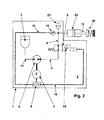
- the basic circuit of the present hydraulic device is in the FIG. 1 shown.
- a hydraulic device 2 is arranged within a common housing 1 schematically represented by a broken outline.
- This consists essentially of an electric motor 3, which is non-positively connected to a positive displacement pump 4, a 2/2-control valve 5, an electrical control unit 6, a reservoir 7, a hydraulic line 8 between the positive displacement pump 4 and the input of 2/2 Control valve 5, a hydraulic line 9 between the output of the 2/2-control valve 5 and a working cylinder 10 and a hydraulic line 11 between the positive displacement pump 4 and the reservoir.
- an electric motor 3 which is non-positively connected to a positive displacement pump 4, a 2/2-control valve 5, an electrical control unit 6, a reservoir 7, a hydraulic line 8 between the positive displacement pump 4 and the input of 2/2 Control valve 5, a hydraulic line 9 between the output of the 2/2-control valve 5 and a working cylinder 10 and a hydraulic line 11 between the positive displacement pump 4 and the reservoir.
- the control unit 6 is connected via a connection 12 with a control device of a higher-level system, for. B. with sensors on a clutch pedal and / or with other sensors that determine certain conditions within a drive train connected. It can generate from it or by manually triggered commands a signal that starts the electric motor 3. With the start of the electric motor 3 at the same time runs the positive displacement pump 4. It sucks hydraulic fluid from the reservoir 7, wherein in the line 8, a higher pressure is built up. The 2/2-control valve 5 is switched in its initial position so that the line 8 and the line 9 are connected to each other, so that the working cylinder 10 is acted upon by a pressure flow and the piston rod 13 is extended to actuate a clutch, not shown.
- a control device of a higher-level system for. B. with sensors on a clutch pedal and / or with other sensors that determine certain conditions within a drive train connected. It can generate from it or by manually triggered commands a signal that starts the electric motor 3. With the start of the electric motor 3 at the same time runs the
- control unit 6 In turn, the control unit 6 generates a command that stops the duty cycle of the working cylinder 10 due to the externally supplied signals, it controls the electric motor 3 and the positive displacement pump 4 in the opposite direction of rotation, so that the working cylinder 10 is sucked empty and therefore retracted.
- the aspirated volume flow is returned to the reservoir 7.
- the displacement pump 4 may be a pump of any embodiment, provided they can deliver the required volume flow and reach the required pressure level.
- hydraulic pumps are suitable as displacement pumps 4, which can perform fast speed changes, including fast starts and changes of direction.
- Pumps for example external gear pumps, in which the displacement chambers are defined or stabilized purely geometrically, are particularly suitable
- a pressure measuring sensor 14 may be connected to the control unit 6 via a signal line 15 so that it can stop the pumping process as soon as the pressure level required for a successful working cycle of the working cylinder 10 is reached.
- control unit 6 can evaluate measurement signals of the pressure measuring sensor 14 and let the positive displacement pump 4 run intermittently or at a lower speed in order to maintain a pressure level dropping due to leaks.
- a preferred embodiment of the hydraulic device provides the arrangement of the 2/2-control valve 5, which can be controlled by an electromagnet 16 and by a spring element 17 is reset.
- the 2/2-control valve 5 In its illustrated first position, which forms the starting position, the 2/2-control valve 5 establishes a connection between the positive displacement pump 4 and the working cylinder 10.
- the control unit 6 can control the electromagnet 16 via the electrical line 18 and control the 2/2-control valve 5 to the second position, in which a seat valve 19 of the 2 / 2-control valve 5, prevents backflow of the hydraulic medium.
- the positive displacement pump 4 must therefore be operated in this application, in an energy-saving manner only to reach the required pressure levels and by switching the control valve 5 in the second position of the working cylinder 10 is held in the extended position.
- a conventional clutch includes a spring assembly 20 which returns the power cylinder 10 to the home position, otherwise a separate spring assembly 20 may be provided for recovery.
- FIG. 2 sees an improved embodiment in the region of the line 9 in addition to a pressure accumulator 21, which may be embodied for example as a disc spring memory.
- a pressure accumulator 21 which may be embodied for example as a disc spring memory. This can ensure by a volume tracking when reaching the extended state of the working cylinder 10 in the second position of the 2/2-control valve 5 that emerging leakage currents are compensated and the required pressure level in the line 9 and in the working cylinder 10 remains.
- an integration of the power requirement during the actuation process can be fulfilled.
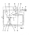
- a further preferred embodiment of the hydraulic device comprises according to FIG. 3 a bypass diaphragm or throttle device 22 arranged parallel to the positive-displacement pump 4.
- the leakage current occurring via the throttle device 22 deliberately reduces the volumetric efficiency the positive displacement pump 4. This has the consequence that the required speed of the electric motor 3 for adjusting a defined pressure in the working cylinder 10 is higher, but this represents significant advantages in terms of speed control / speed control with small required flow rates.
- FIG. 4 Another embodiment of the hydraulic device provides according to FIG. 4 a working cylinder 23 in double-acting design before.
- the positive displacement pump 4 is controlled by the electric motor 3 so that it fills the working cylinder 23 (left chamber) via the line 24 and this extends.
- positive displacement pump 4 is reversed or reversed. It then fills via the line 25 the working cylinder 23 (right chamber), whereby this retracts again.
- the two ports 26 and 27 of the positive displacement pump 4 are connected with the interposition of seat and check valves 28 and 29 with the conduit 11 and the reservoir 7.
- the positive displacement pump 4 opens either the seat valve 29 during extension of the working cylinder 23 and seat valve 28 when retracting the same.
- control unit 6 can continue to run the positive displacement pump 4, wherein an excessively promoted volume flow through the pressure relief valves 31 and 32 derived and via the lines 33 and 34 is supplied to the storage container 7.
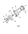
- a modular housing comprising a local controller 35, a motor-pump housing 40, a valve-accumulator housing 46, a cover plate 49 and a 2/2-control valve 45 flanged to the valve accumulator housing 46 built a compact unit that combines all functions in terms of inventory of the hydraulic medium, generating a volume flow and signal processing in it.
- This compact unit requires in their use only the production of hydraulic and electrical connections and the connections of the sensors arranged outside.
- the compactness of this assembly makes it possible to arrange it largely free of restrictions at locations within vehicles or facilities. For example, there is a possibility to arrange the compact unit near the clutch actuating hydraulic cylinder (slave cylinder).
- the stator 37 and the rotor 38 of the electric motor are arranged so that the shaft of the electric motor can support the impeller 41.
- the bearing glasses 42 are arranged, wherein the overall arrangement corresponds to the construction of a gear pump.
- the bearing goggles 42 of the impeller 41 also form the bearing of the rotor 38 of the electric motor.
- One of the two bearings can alternatively be accommodated in the valve accumulator Geäuse 46.
- the second bearing point of the pump goggles in the motor-pump housing 40 are laid.
- a filling opening allows the filling of the tank space 43. It is covered with a cap 50.
- the storage space 44 is arranged, which has a variable volume in cooperation with a center cover 48 and a plate spring 47 and assumes the task of a pressure accumulator as mentioned above.
- a 2/2-way control valve 45 is disposed between the end cover 49 and the motor-pump housing 30. It serves to control the volume flow leading to the slave cylinder.
- a speed-rotation angle sensor 39 is further combined ( FIG. 6 ), so that an exact control of the compact hydrostatic device for clutch actuation is possible
- the cohesion of the individual segments of the hydraulic device can in different ways, for example by screwing the units together, by suitable permanent connections between the units or as in Fig. 5 and Fig. 6 represented by studs, realized.
- the application of the hydraulic device according to the invention is not limited to not only the operation of clutches, such as clutches for dual clutch transmissions, hybrid disconnect clutches, step machines and manual transmissions in general.
- the present hydraulic devices can also be used for the connection of all-wheel drives (AWD), the operation of a differential gear or a parking lock.
- AWD all-wheel drives
- Hydrostatic devices that work with double-acting cylinders can be used in addition to clutches for gear, AWD and parking lock circuits.
- the invention thus advantageously provides options for designing a compact hydraulic device to be adapted to the respective requirement image in such a way that it can be precisely controlled, can save energy and can be installed without problems in the fields of application in question due to its compact design.
Landscapes
- Engineering & Computer Science (AREA)
- General Engineering & Computer Science (AREA)
- Mechanical Engineering (AREA)
- Physics & Mathematics (AREA)
- Fluid Mechanics (AREA)
- Power Engineering (AREA)
- Hydraulic Clutches, Magnetic Clutches, Fluid Clutches, And Fluid Joints (AREA)
- Fluid-Pressure Circuits (AREA)
Description
- Die Erfindung betrifft eine hydraulische Einrichtung zur Betätigung einer Kupplung.
- Bekannt sind hydraulische Kraftübertragungsstrecken mit Nehmer- und Geberzylindem. Der hydraulische Nehmerzylinder ist hierbei der Kupplung örtlich nahe zugeordnet. Bei automatisierten Übertragungsstrecken kann der Geberzylinder als eine steuerbare und/oder regelbare Volumenstromquelle ausgeführt sein.
- Es sind grundsätzlich zwei Arten von Volumenstromquellen für derartige Kraftübertragungsstrecken bekannt. Dabei handelt es sich in einem Fall um eine Teilfunktion einer komplexeren hydraulischen Steuerung, die noch weitere Aufgaben erfüllen kann. Die Volumenströme einer mechanisch oder elektrisch angetriebenen Hydraulikpumpe werden dabei über eine Ventillogik aufgeteilt und ein Teilstrom wird zur Kupplungsbetätigung verwendet Diese Lösung ist aufwendig, wenn nur eine oder zwei hydraulische Funktionen benötigt werden.
- In einem anderen Fall wird ein sogenannter Hydrostataktor als Volumenstromquelle eingesetzt Derartige Lösungen sind beispielsweise in der Druckschrift
WO 2011050767 A1 oderDE 2008 039011 beschrieben. Dabei wird eine Drehbewegung eines elektrischen Antriebs auf eine Gewindespindel übertragen, die mit als Planeten um die Gewindespindel herum angeordneten weiteren Gewindespindeln im Kontakt steht und auf diese Weise eine lineare Bewegung der Planeten erzeugt, die wiederum eine Verbindung mit einem Verdrängerkolben haben und diesen linear hin und her bewegen. Allerdings kann sich die große Übersetzung der Drehbewegung in die Linearbewegung negativ auf das Hystereseverhalten und die Dynamik auswirken. - Die Aufgabe der Erfindung besteht darin, eine hydraulische Einrichtung zur Betätigung einer Kupplung bereitzustellen, die als kompakte Einheit ausführbar ist, ein deutlich verbessertes Ansprechverhalten hat, die sich in fahrzeuginterne Steuerungssysteme integrieren lässt, aber auch solitär betrieben werden kann, weitgehend wartungsfrei arbeitet und im Übrigen die bei den Lösungen des Standes der Technik aufgezeigten Nachteile nicht aufweist
- Die Aufgabe wird gelöst mit einer hydraulische Einrichtung zur Betätigung einer Kupplung, mit den Merkmalen des kennzeichnenden Teils des Patentanspruches 1 in Verbindung mit den Merkmalen des Oberbegriffes dieses Anspruches.
- Demgemäß betrifft die vorliegende Erfindung eine hydraulische Einrichtung, insbesondere zur Betätigung einer Kupplung, mit einem nahe der Kupplung angeordneten hydraulischen Arbeitszylinder, wobei der Arbeitszylinder über eine hydraulische Leitung mit einer Volumenstromquelle verbunden ist. Der Volumenstrom der Volumenstromquelle ist durch eine Steuereinheit in Abhängigkeit von Signalen der der hydraulischen Einrichtung zugeordneten Sensoren beeinflussbar. Die Volumenstromquelle ist durch eine in einem gemeinsamen Gehäuse angeordnete Kombination bzw. Einheit aus einem Elektromotor und einer Pumpe gebildet.
- Gemäß der vorliegenden der Erfindung wird der oben beschriebene Hydrostataktor dergestalt weiterentwickelt, dass vorteilhafterweise anstelle eines voluminösen Verdrängerkolbens und eines komplizierten Planetengetriebes eine vergleichsweise einfache Pumpenanordnung verwendet werden kann, deren Drehzahl reversiert werden kann. Eine solche Einrichtung kann gemäß einem Vorteil der vorliegenden Erfindung kleiner als ein Hydrostataktor gebaut werden und lässt sich in vielfacher Weise an Einsatzbedingungen anpassen, wodurch die Freizügigkeit bei der Anordnung bzw. beim Einbau zusätzlich verbessert wird. Die erfinderische Lösung besteht also darin den Verdrängerkolben und das Planetengetriebe des Hydrostataktors durch eine spezielle Pumpenanordnung zu ersetzen.
- Die erfindungsgemäße hydraulische Einrichtung kann beispielsweise zur Versorgung und Ansteuerung einfach wirkender Hydraulikzylinder verwendet werden. Eine Kombination aus einem Elektromotor und einer Hydraulikpumpe ist so ausgelegt, dass ein schneller Druckaufbau und bei Bedarf ein schneller Drehrichtungswechsel möglich sind. Elektromotor und Pumpe sind deshalb so ausgelegt, dass sie mit hoher Dynamik auf Änderungen reagieren können. Rotierende Teile sind deshalb zur Verminderung von Trägheiten möglichst klein dimensioniert.
- Bei den Hydraulikpumpen ist vorteilhafterweise jede Ausführungsform geeignet, die unmittelbar mit dem Anlauf einen großen Volumenstrom und ein hohes Druckniveau gewährleisten kann. Geeignete Bauformen hierfür sind Zahnrad-, Flügelrad-, Drehschieber-, Radial- oder Axialkolbenpumpen.
- Wird eine Kupplung mit der vorliegenden hydraulischen Einrichtung betätigt, wird die Pumpe durch den Elektromotor angetrieben, so dass das Fluid in Richtung zum Arbeitszylinder (Nehmerzylinder) gefördert wird. Ein Sensorsystem überwacht hierbei den Betätigungszustand der Kupplung, des Kupplungsausrückers oder des Arbeitszylinders. Über Sensorsignale können die Pumpendrehzahl und / oder die Pumpenlaufdauer permanent geregelt werden, um den Zielzustand der Kupplung zu erhalten. Das Sensorsignal kann von einer Wegmessung an der Kupplung oder einer Druckmessung in der hydraulischen Strecke zur Kupplung oder von beiden generiert werden.
- Zum Halten der Kupplung in der Zielposition gibt es die folgenden bevorzugten Möglichkeiten. Im einen Fall wird die Drehzahl der Pumpe so weit reduziert, dass sie nur noch ihren eigenen Leckagestrom ausgleicht. Das heißt, die Pumpe hält den Druck, ohne dass weiteres zusätzliches Fluid in die hydraulische Strecke zur Kupplung gefördert wird und die Kupplung eine zusätzliche Betätigung erfährt. Es wird also lediglich der Leckagestrom ausgeglichen. Vorteilhaft ist es hierbei, dass keine weiteren Bauteile zum Halten der Kupplungsposition notwendig sind. Allerdings muss permanent Energie zum Halten der Kupplung aufgebracht werden.
- Im anderen Fall ist ein Ventil vorgesehen, das die Hydraulikstrecke zwischen Pumpe und Kupplung verschließt, sobald die Zielposition der Kupplung erreicht ist. Mit besonderem Vorteil wird als Ventil ein Sitzventil (Rückschlagventil) gewählt Die sehr geringe Leckage des Sitzventils ermöglicht es, dass die Pumpe und damit der Elektromotor nicht permanent getrieben werden müssen, um die Kupplung in der Zielposition zu halten. Der Energiebedarf für die Betätigung des Ventils ist dabei geringer als das Betreiben des Elektromotors zum Halten der Kupplung ohne Ventil. Allerdings wird ein zusätzliches Bauteil in der Form eines Elektromagneten zum Betätigen des Ventils benötigt
- Zum Deaktivieren der Kupplung können folgende Strategien eingesetzt werden. Die Pumpe kann aktiv entgegen ihrer Förderrichtung betrieben (reversiert) werden, um die hydraulische Strecke schnell zu entleeren. Bei diesem Vorgang kann es erforderlich sein, dass der Betätigungszustand der Kupplung über eine Sensorik überwacht wird. Nach dem so genannten Kiss-Point der Kupplung wird in der Regel keine große Dynamik bzw. eine geringere Dynamik bezüglich der weiteren Öffnung gefordert. Um ein Leersaugen der hydraulischen Strecke zu verhindern, kann ab dem Kiss-Point oder kurz danach die Pumpendrehzahl auf Null gebracht werden. Die Restentleerung der hydraulischen Strecke kann dann über die Spalte der Pumpe erfolgen.
- Bei dynamisch unkritischen Vorgängen ist es vorstellbar, dass die in der Kupplung und der hydraulischen Strecke gespeicherte Energie teilweise zurückgewonnen werden kann. Die Pumpe arbeitet dann als hydraulischer Motor und der Elektromotor als Generator.
- Wenn das System zusätzlich noch ein Verriegelungsventil aufweist, ist dieses zeitgleich mit oder vor der Deaktivierung der Kupplung zu öffnen. Eine Auslegung des hydraulischen Systems der Einrichtung kann durch den Fachmann auf vielfältige Weise erfolgen. So kann eine Auslegung unter anderem nach den Erfordernissen der anzusteuernden Kupplung, nach äußeren Anforderungen, wie beim Fahrzeugbetrieb, sowie unter Optimierungs- und energetischen Gesichtspunkten erfolgen.
- Es ist bei einer vorteilhaften Ausgestaltung der Erfindung auch möglich zwischen der Kupplung und dem Ventil in dem gemeinsamen Gehäuse einen Druckspeicher anzuordnen. Dieser Druckspeicher kann zum Beispiel als Tellerfederspeicher ausgeführt sein. Der Druckspeicher kann je nach seiner Auslegung zwei unterschiedliche Funktionen erfüllen. Einerseits kann er eine Reduzierung des Leistungsbedarfes beim Betätigungsvorgang bewirken und andererseits kann er für eine Volumennachführung beim Halten der Kupplung zum Ausgleich auftretender Leckagen sorgen.
- Neben der oben beschriebenen Versorgung eines einfach wirkenden Zylinders kann mittels der Reversierpumpeneinheit, die aus einem Elektromotor mit Elektronik zum Steuern und/oder Regeln der Pumpleistung und der Hydraulikpumpe besteht, auch ein doppelt wirkender Zylinder angesteuert werden. Im einfachsten Fall wird mittels der Reversierpumpeneinheit gezielt das Volumen von einer Zylinderkammer in die andere Zylinderkammer gefördert. Wenn die Volumina der beiden Zylinderräume unterschiedlich groß sind, kann ein einfaches Umpumpen des Fluids vom einen in den anderen Zylinderraum nicht erfolgen. In diesem Fall kann eine Anordnung von sogenannten Nachsauge- und Überdruckventilen für einen ausgeglichenen Fluidhaushalt sorgen.
- Die erfindungsgemäße hydraulische Einrichtung mit der Kombination aus Elektromotor und Pumpe kann vorteilhafterweise sehr kompakt aufgebaut sein und die folgenden Merkmale aufweisen. Der Rotor und der Stator des Elektromotors können sich mit der Verdrängereinheit der Pumpe ein gemeinsames Gehäuse teilen. Der Rotor des Elektromotors kann vollständig oder teilweise in den Lagerbrillen der Zahnradpumpe gelagert werden. Eine Lagerstelle des Elektromotors bzw. der Pumpe kann auch in das Ventiloder das Druckspeichergehäuse gelegt werden. Die Ventileinheit und der Tellerfederdruckspeicher können sich ein weiteres Gehäuseteil teilen. DerTankraum kann zwischen dem Motor-/ Pumpengehäuse und dem Ventil- bzw. Druckspeichergehäuse angeordnet sein. Je nach Anwendungsfall kann die Ventileinheit ausgetauscht und ggf. auf die Speicherfunktion verzichtet werden. Die systemrelevante Sensorik d.h. die Drehzahl-, Drehwinkel- und / oder Drucksensorik kann direkt in die Steuerelektronik der Elektromotor/Pumpenkombination integriert werden. Die besondere Kompaktheit dieser Kombination ermöglicht in vielen Fällen eine örtliche Nähe zum Aktor, so dass auch eine Wegmessung in die Steuerelektronik integrierbar ist Die Spule für den Elektromagneten des Ventils kann ebenfalls direkt in Steuereinheit integriert sein.
- Bei einer weiteren Ausführungsform der Erfindung kann eine Bypassblende oder eine Bypassdrossel zwischen den Pumpenanschlüssen vorgesehen sein, um eine gezielte "Verschlechterung" des volumetrischen Wirkungsgrads der Pumpe herbeizuführen. Damit wird die "Druckhaltedrehzahl" erhöht und somit die Regelbarkeit des Druckes verbessert.
- Die Erfindung wird nachstehend anhand von Ausführungsbeispielen und Zeichnungen näher erläutert. Dabei zeigen:
- Figur 1
- das hydraulische Schema einer erfindungsgemäßen hydraulischen Einrichtung mit einem einfach wirkenden Hydraulikzylinder mit Federrückstellung und mit einer elektrisch angetriebenen Reversierpumpe, einem Steuerventil, einem Hochtank und einem Drucksensor;
- Figur 2
- eine im Vergleich zur Einrichtung der
Figur 1 weiter entwickelte erfindungsgemäße Einrichtung, bei der ein zusätzlicher Druckspeicher vorgesehen ist; - Figur 3
- eine erfindungsgemäße hydraulische Einrichtung, bei der ein Bypass parallel zur Reversierpumpe angeordnet ist;
- Figur 4
- eine erfindungsgemäße hydraulische Einrichtung zur Ansteuerung eines doppelt wirkenden Arbeitszylinders;
- Figur 5
- eine perspektivische Darstellung der erfindungsgemäßen hydraulischen Einrichtung mit einem kompakten Einheitsgehäuse für alle Komponenten Einrichtung, zum Teil in Explosionsdarstellung; und
- Figur 6
- eine Schnittdarstellung des kompakten Einheitsgehäuses der
Figur 5 mit allen darin angeordneten Einzelkomponenten. - Die Grundschaltung der vorliegenden hydraulischen Einrichtung ist in der
Figur 1 dargestellt. - Innerhalb eines durch eine unterbrochene Umrisslinie schematisch dargestellten gemeinsamen Gehäuses 1 ist eine hydraulische Einrichtung 2 angeordnet. Diese besteht im wesentlichen aus einem Elektromotor 3, der mit einer Verdrängerpumpe 4 kraftschlüssig verbunden ist, einem 2/2-Steuerventil 5, einer elektrischen Steuereinheit 6, einem Vorratsbehälter 7, einer hydraulischen Leitung 8 zwischen der Verdrängerpumpe 4 und dem Eingang des 2/2-Steuerventils 5, einer hydraulischen Leitung 9 zwischen dem Ausgang des 2/2-Steuerventils 5 und einem Arbeitszylinder 10 sowie einer hydraulischen Leitung 11 zwischen der Verdrängerpumpe 4 und dem Vorratsbehälter 7.
- Die Steuereinheit 6 ist über einen Anschluss 12 mit einer Steuereinrichtung eines übergeordneten Systems, z. B. mit Sensoren an einem Kupplungspedal und/oder mit weiteren Sensoren, die bestimmte Zustände innerhalb eines Antriebsstranges ermitteln, verbunden. Sie kann daraus oder durch manuell ausgelöste Befehle ein Signal generieren, das den Elektromotor 3 anlaufen lässt. Mit dem Anlaufen des Elektromotors 3 läuft zugleich die Verdrängerpumpe 4 an. Sie saugt Hydraulikflüssigkeit aus dem Vorratsbehälter 7, wobei in der Leitung 8 ein höherer Druck aufgebaut wird. Das 2/2-Steuerventil 5 ist in seiner Ausgangsstellung so geschaltet, dass die Leitung 8 und die Leitung 9 miteinander verbunden sind, sodass der Arbeitszylinder 10 mit einem Druck-Volumenstrom beaufschlagt und die Kolbenstange 13 zur Betätigung einer nicht dargestellten Kupplung ausgefahren wird.
- Generiert die Steuereinheit 6 wiederum aufgrund der von außen gelieferten Signale einen Befehl, der den Arbeitszyklus des Arbeitszylinders 10 beendet, steuert sie den Elektromotor 3 und die Verdrängerpumpe 4 in die entgegengesetzte Drehrichtung, sodass der Arbeitszylinder 10 leer gesaugt und daher eingefahren wird. Der abgesaugte Volumenstrom wird in den Vorratsbehälter 7 zurückbefördert.
- Bei der oben beschriebenen Arbeitsweise kann auch auf das 2/2-Steuerventil 5 verzichtet werden und die Leitungen 8 und 9 können direkt miteinander verbunden werden.
- Die Verdrängerpumpe 4 kann eine Pumpe beliebiger Ausführungsform sein, sofern sie den geforderten Volumenstrom liefern und das geforderte Druckniveau erreichen kann. Insbesondere sind als Verdrängerpumpen 4 Hydraulikpumpen geeignet, die schnelle Drehzahländerungen, inklusive schnelle Anläufe und Drehrichtungswechsel ausführen können. Besonders geeignet sind Pumpen, beispielsweise Außenzahnradpumpen, bei denen die Verdrängungsräume rein geometrisch definiert bzw. stabilisiert sind, geeignet
- Ein Druckmesssensor 14 kann über eine Signalleitung 15 mit der Steuereinheit 6 verbunden sein, sodass diese die den Pumpvorgang stoppen kann, sobald das für einen erfolgreichen Arbeitszyklus des Arbeitszylinders 10 erforderliche Druckniveau erreicht ist.
- Ebenso kann die Steuereinheit 6 Messsignale des Druckmesssensors 14 auswerten und die Verdrängerpumpe 4 intermittierend oder auch mit geringerer Drehzahl laufen lassen, um ein aufgrund von Leckagen abfallendes Druckniveau aufrecht zu erhalten.
- Eine bevorzugte Ausführungsform der hydraulischen Einrichtung sieht die Anordnung des 2/2-Steuerventils 5 vor, das durch einen Elektromagneten 16 ansteuerbar und durch ein Federelement 17 rückstellbar ist. In seiner dargestellten ersten Stellung, die die Ausgangsstellung bildet, stellt das 2/2-Steuerventil 5 eine Verbindung zwischen der Verdrängerpumpe 4 und dem Arbeitszylinder 10 her. Sobald der Druckmesssensor 14 an die Steuereinheit 6 das Erreichen des geforderten Druckniveaus meldet, kann die Steuereinheit 6 über die elektrische Leitung 18 den Elektromagneten 16 ansteuern und das 2/2-Steuerventil 5 in die zweite Stellung steuern, in der ein Sitzventil 19 des 2/2-Steuerventils 5, ein Rückfließen des Hydraulikmediums verhindert.
- Die Verdrängerpumpe 4 muss bei diesem Anwendungsfall also in energiesparender Weise nur bis zum Erreichen des geforderten Druckniveaus betrieben werden und durch das Umschalten des Steuerventils 5 in die zweite Stellung wird der Arbeitszylinders 10 in der ausgefahrenen Stellung gehalten.
- Eine übliche Kupplung beinhaltet eine Federanordnung 20, welche den Arbeitszylinder 10 in die Ausgangsstellung zurückstellt, ansonsten kann eine separate Federanordnung 20 zur Rückstellung vorgesehen sein.
- Gemäß
Figur 2 sieht eine verbesserte Ausführungsform im Bereich der Leitung 9 zusätzlich einen Druckspeicher 21 vor, der beispielsweise als Tellerfederspeicher ausgeführt sein kann. Dieser kann durch eine Volumennachführung bei Erreichen des ausgefahrenen Zustandes des Arbeitszylinders 10 in der zweiten Stellung des 2/2-Steuerventils 5 dafür sorgen, dass auftretende Leckströme ausgeglichen werden und das geforderte Druckniveau in der Leitung 9 und in dem Arbeitszylinder 10 bestehen bleibt. Außerdem kann eine Integration des Leistungsbedarfes beim Betätigungsvorgang erfüllt werden. - Eine weitere bevorzugte Ausführungsform der hydraulischen Einrichtung umfasst gemäß
Figur 3 eine parallel zur Verdrängerpumpe 4 angeordnete Bypassblende bzw. Drosseleinrichtung 22. Der über die Drosseleinrichtung 22 auftretende Verluststrom mindert zwar bewusst den volumetrischen Wirkungsgrad der Verdrängerpumpe 4. Dies hat zur Folge, dass die erforderliche Drehzahl des Elektromotors 3 zur Einregelung eines definierten Drucks im Arbeitszylinder 10 höher wird, was aber bezüglich der Drehzahlsteuerung / Drehzahlregelung bei kleinen erforderlichen Förderströmen deutliche Vorteile darstellt. - Eine weitere Ausführungsform der hydraulischen Einrichtung sieht gemäß
Figur 4 einen Arbeitszylinder 23 in doppelt wirkender Ausführung vor. Die Verdrängerpumpe 4 wird dabei durch den Elektromotor 3 so angesteuert, dass sie über die Leitung 24 den Arbeitszylinders 23 (linke Kammer) füllt und dieser ausfährt. Am Ende des Arbeitszyklus wird Verdrängerpumpe 4 umgesteuert bzw. reversiert. Sie füllt dann über die Leitung 25 den Arbeitszylinder 23 (rechte Kammer), wodurch dieser wieder einfährt. Die beiden Anschlüsse 26 und 27 der Verdrängerpumpe 4 sind unter Zwischenschaltung von Sitz- bzw. Rückschlagventilen 28 und 29 mit der Leitung 11 und dem Vorratsbehälter 7 verbunden. Je nach Drehrichtung der Verdrängerpumpe 4 öffnet entweder das Sitzventil 29 beim Ausfahren des Arbeitszylinders 23 und Sitzventil 28 beim Einfahren desselben. Für den Fall, dass die den Eingängen des Arbeitszylinders 23 zugeordneten Druckmesssensoren 14 oder 30 einen Druckverlust signalisieren, kann die Steuereinheit 6 die Verdrängerpumpe 4 weiter laufen lassen, wobei ein zu viel geförderter Volumenstrom über die Druckbegrenzungsventile 31 und 32 abgeleitet und über die Leitungen 33 bzw. 34 dem Vorratsbehälter 7 zugeführt wird. - Im Zusammenhang mit den
Figuren 5 und6 wird nachfolgend eine derzeit bevorzugte Ausführungsform der Erfindung beschrieben. - Mit einem modular aufgebauten Gehäuse, das ein lokales Steuergerät 35, ein Motor-Pumpen-Gehäuse 40, ein Ventil-Druckspeicher-Gehäuse 46, einen Abschlussdeckel 49 und ein am Ventil-Druckspeicher-Gehäuse 46 angeflanschtes 2/2-Steuerventil 45 umfasst, wird eine kompakte Baueinheit aufgebaut, die alle Funktionen hinsichtlich Vorratshaltung des hydraulischen Mediums, Erzeugung eines Volumenstromes und Signalverarbeitung in sich vereinigt.
- Diese kompakte Baueinheit bedarf bei ihrer Verwendung lediglich noch der Herstellung der hydraulischen und der elektrischen Anschlüsse sowie der Anschlüsse der außerhalb angeordneten Sensoren. Die Kompaktheit dieser Baueinheit ermöglicht es, sie weitgehend frei von Beschränkungen an Orten innerhalb von Fahrzeugen oder Anlagen anzuordnen. So besteht beispielsweise eine Möglichkeit, die kompakte Baueinheit nahe dem die Kupplung betätigenden hydraulischen Arbeitszylinder (Nehmerzylinder) anzuordnen.
- Im Motor-Pumpen-Gehäuse 40 sind der Stator 37 und der Rotor 38 des Elektromotors so angeordnet, dass die Welle des Elektromotors das Pumpenrad 41 tragen kann. Beidseitig des Pumpenrades 41 sind die Lagerbrillen 42 angeordnet, wobei die Gesamtanordnung dem Aufbau einer Zahnradpumpe entspricht. Die Lagerbrillen 42 des Pumpenrades 41 bilden auch die Lagerung des Rotors 38 des Elektromotors. Eine der beiden Lagerstellen kann alternativ auch im Ventil-Druckspeicher-Geäuse 46 untergebracht sein. Selbstverständlich kann in Analogie dazu auch die zweite Lagerstelle von der Pumpenbrille ins Motor-Pumpen-Gehäuse 40 verlegt werden.
- Das Motor-Pumpen-Gehäuse 40 und der Abschlussdeckel 49 bilden gemeinsam einen Tankraum 43 aus, der das hydraulische Medium aufnimmt. Eine Einfüllöffnung lässt das Befüllen des Tankraums 43 zu. Sie wird mit einer Verschlusskappe 50 abgedeckt.
- Im Abschlussdeckel 49 ist fener der Speicherraum 44 angeordnet, der im Zusammenwirken mit einem Mitteldeckel 48 und einer Tellerfeder 47 ein veränderliches Volumen hat und die Aufgabe eines wie oben erwähnten Druckspeichers übernimmt.
- Ein 2/2-Steuerventil 45 ist zwischen dem Abschlussdeckel 49 und dem Motor-Pumpen-Gehäuse 30 angeordnet. Es dient der Steuerung des zum Nehmerzylinder zu führenden Volumenstroms.
- Mit dem lokalen Steuergerät 35 ist ferner eine Drehzahl-Drehwinkel-Sensorik 39 kombiniert (
Figur 6 ), sodass eine exakte Steuerung der kompakten hydrostatischen Einrichtung zur Kupplungsbetätigung möglich ist - Der Zusammenhalt der einzelnen Segmente der hydraulischen Einrichtung kann auf verschiedene weise, beispielsweise durch Verschrauben der Baueinheiten untereinander, durch geeignete unlösbare Verbindungen zwischen den Einheiten oder wie in
Fig. 5 undFig. 6 dargestellt, durch Stehbolzen, realisiert werden. - Die Anwendung der erfindungsgemäßen hydraulischen Einrichtung beschränkt sich nicht nicht nur auf die Betätigung von Kupplungen, wie beispielsweise Kupplungen für Doppelkupplungsgetriebe, Hybridtrennkupplungen, Stufenautomaten und Schaltgetriebe allgemein. Die vorliegenden hydraulischen Einrichtungen können auch für die Zuschaltung von Allradantrieben (AWD), die Betätigung eines Differenzialgetriebes oder eine Parksperre eingesetzt werden. Hydrostatische Einrichtungen, die mit doppelt wirkenden Arbeitszylindern zusammenarbeiten, können neben Kupplungen auch für Gangsteller, AWD-Zuschaltung und Parksperrenschaltungen verwendet werden.
- Die Erfindung schafft also vorteilhafterweise Möglichkeiten, eine an das jeweilige Anforderungsbild anzupassende kompakte hydraulische Einrichtung so auszugestalten, dass sie präzise steuerbar ist, energiesparend arbeiten kann und zudem in den in Frage kommenden Einsatzgebieten aufgrund ihrer kompakten Bauweise ohne Probleme verbaut werden kann.
-
- 1
- Gehäuse
- 2
- hydraulische Einrichtung
- 3
- Elektromotor
- 4
- Verdrängerpumpe
- 5
- 2/2-Steuerventil
- 6
- Steuereinheit
- 7
- Vorratsbehälter
- 8
- Leitung
- 9
- Leitung
- 10
- Arbeitszylinder
- 11
- Leitung
- 12
- Anschluss
- 13
- Kolbenstange
- 14
- Druckmesssensor
- 15
- Signalleitung
- 16
- Elektromagnet
- 17
- Federelement
- 18
- Leitung
- 19
- Sitzventil
- 20
- Federanordnung
- 21
- Druckspeicher
- 22
- Drosseleinrichtung
- 23
- Arbeitszylinder
- 24
- Leitung
- 25
- Leitung
- 26
- Anschluss
- 27
- Anschluss
- 28
- Sitzventil
- 29
- Sitzventil
- 30
- Druckmesssensor
- 31
- Druckbegrenzungsventil
- 32
- Druckbegrenzungsventil
- 33
- Leitung
- 34
- Leitung
- 35
- lokales Steuergerät
- 36
- integrierter Drucksensor
- 37
- Stator
- 38
- Rotor
- 39
- Drehzahl-Drehwinkel-Sensorik
- 40
- Motor-Pumpen-Gehäuse
- 41
- Pumpenrad
- 42
- Lagerbrille
- 43
- Tankraum
- 44
- Speicherraum
- 45
- 2/2-Steuerventil
- 46
- Ventil-Druckspeicher-Gehäuse
- 47
- Tellerfeder
- 48
- Mitteldeckel
- 49
- Abschlussdeckel
- 50
- Verschlusskappe
Claims (10)
- Hydraulische Einrichtung, insbesondere zur Betätigung einer Kupplung, mit einem nahe der Kupplung angeordneten hydraulischen Arbeitszylinder (10),
wobei der Arbeitszylinder (10) über eine hydraulische Leitung (8, 9) mit einer Volumenstromquelle verbunden ist und wobei der Volumenstrom der Volumenstromquelle durch eine Steuereinheit (6) in Abhängigkeit von Signalen der der hydraulischen Einrichtung (2) zugeordneten Sensoren steuerbar ist, wobei die Volumenstromquelle durch eine in einem gemeinsamen Gehäuse (1) angeordnete Kombination aus einem Elektromotor (3) und einer hydraulischen Pumpe (4) gebildet ist, dadurch gekennzeichnet, dass in dem gemeinsamen Gehäuse (1) die Steuereinheit (6) angeordnet ist. - Hydraulische Einrichtung nach Anspruch 1,
dadurch gekennzeichnet, dass die Pumpe (4) eine Verdrängerpumpe, vorzugsweise in der Form einer Zahnradpumpe, einer Flügelzellenpumpe, einer Radialkolbenpumpe oder einer Axialkolbenpumpe ist. - Hydraulische Einrichtung nach Anspruch 1 oder 2,
dadurch gekennzeichnet, dass die Kombination aus dem Elektromotor (3) und der Pumpe (4) in zwei Drehrichtungen betreibbar ist. - Hydraulische Einrichtung nach einem der Ansprüche 1 bis 3,
dadurch gekennzeichnet, dass der Pumpe (4) eine Drosseleinrichtung (22) parallel geschaltet ist. - Hydraulische Einrichtung nach Anspruch 1,
dadurch gekennzeichnet, dass in dem gemeinsamen Gehäuse (1) ein Vorratsbehälter (7) für das hydraulische Medium und/oder ein Druckspeicher (21) angeordnet sind. - Hydraulische Einrichtung nach einem der Ansprüche 1 bis 5,
dadurch gekennzeichnet, dass die Steuereinheit (6) Komponenten umfasst, die Messsignale von Sensoren verarbeiten kann, die innerhalb der hydraulischen Einrichtung (2) oder außerhalb derselben angeordnet sind, wobei die Messsignale Signale des Elektromotors (3) und/oder der Pumpe (4), und/oder Druckmesswerte und Wegmesswerte des Arbeitszylinders (10) und/oder Signale eines durch den Arbeitszylinder angetriebenen externen Elements umfassen. - Hydraulische Einrichtung nach einem der Ansprüche 1 bis 6,
dadurch gekennzeichnet, dass der Arbeitszylinder (10) ein einfach wirkender Arbeitszylinder (10), ein einfach wirkender Arbeitszylinder mit einer Federanordnung (20) zur Rückstellung oder ein doppelt wirkender Arbeitszylinder (23) ist. - Verfahren zur Betätigung eines Arbeitszylinders mit einer hydraulischen Einrichtung, nach einem der Ansprüche 1 bis 7,
dadurch gekennzeichnet, dass die hydraulische Einrichtung (2) über ihre Steuereinheit (6) einen durch ein Stellorgan oder durch eine Steuerung generierten Startbefehl erhält, dass die Steuereinheit (6) nachfolgend die Kombination aus dem Elektromotor (3) und der Pumpe (4) in Betrieb setzt und wenigstens einen Arbeitszyklus ausführt, durch den der Arbeitszylinder (10) ausgefahren wird, und dass die Steuereinheit (6) nach Erhalt eines Beendigungssignals einen Druckabfall im Leitungssystem veranlasst, wobei der Arbeitszylinder (10) eingefahren wird.. - Verfahren nach Anspruch 8, dadurch gekennzeichnet, dass nach erfolgtem Druckaufbau im Arbeitszylinder (10) ein Sitzventil (19) geschlossen wird, um die hydraulische Strecke zwischen der Pumpe (4) und dem Arbeitszylinder (10) zu verschließen.
- Verfahren nach Anspruch 8 oder 9, dadurch gekennzeichnet, dass der Druckabfall nach Beendigung eines Arbeitszyklus durch eine Druckentlastung im Arbeitszylinder (10), durch Öffnen des Sitzventils (19), durch Steuern der Kombination aus dem Elektromotor (3) und der Pumpe (4) in den Reversierbetrieb oder durch Spaltverluste in der Pumpe (4) erfolgt.
Applications Claiming Priority (3)
| Application Number | Priority Date | Filing Date | Title |
|---|---|---|---|
| DE102011012180 | 2011-02-23 | ||
| DE102011083880 | 2011-09-30 | ||
| PCT/DE2012/000129 WO2012113368A2 (de) | 2011-02-23 | 2012-02-14 | Hydraulische einrichtung zur betätigung einer kupplung |
Publications (2)
| Publication Number | Publication Date |
|---|---|
| EP2678570A2 EP2678570A2 (de) | 2014-01-01 |
| EP2678570B1 true EP2678570B1 (de) | 2015-04-29 |
Family
ID=46026576
Family Applications (1)
| Application Number | Title | Priority Date | Filing Date |
|---|---|---|---|
| EP12718564.3A Revoked EP2678570B1 (de) | 2011-02-23 | 2012-02-14 | Hydraulische einrichtung zur betätigung einer kupplung |
Country Status (5)
| Country | Link |
|---|---|
| US (1) | US20130333366A1 (de) |
| EP (1) | EP2678570B1 (de) |
| KR (2) | KR102198076B1 (de) |
| DE (2) | DE102012202162A1 (de) |
| WO (1) | WO2012113368A2 (de) |
Cited By (1)
| Publication number | Priority date | Publication date | Assignee | Title |
|---|---|---|---|---|
| DE102016115925B4 (de) | 2016-08-26 | 2022-08-11 | Gkn Automotive Ltd. | System zur hydraulischen Betätigung einer Parksperre |
Families Citing this family (46)
| Publication number | Priority date | Publication date | Assignee | Title |
|---|---|---|---|---|
| DE102012218977B4 (de) | 2012-10-18 | 2022-01-05 | Schaeffler Technologies AG & Co. KG | Hydrostatisch betätigtes Doppelkupplungssystem sowie Verfahren zu dessen Betätigung |
| DE112014000470A5 (de) | 2013-01-18 | 2015-09-24 | Schaeffler Technologies AG & Co. KG | Fluidisches System und Verfahren zum Ansteuern einer Kupplungseinrichtung |
| DE112014002121A5 (de) | 2013-04-25 | 2016-01-14 | Schaeffler Technologies AG & Co. KG | Hydrostatisches Kupplungsbetätigungssystem |
| WO2015010696A2 (de) | 2013-07-24 | 2015-01-29 | Schaeffler Technologies Gmbh & Co. Kg | Hydrauliksystem |
| DE102014213489A1 (de) * | 2013-07-31 | 2015-02-05 | Schaeffler Technologies Gmbh & Co. Kg | Hydraulisches Betätigungssystem |
| DE112014004555A5 (de) * | 2013-10-01 | 2016-07-07 | Schaeffler Technologies AG & Co. KG | Positionierung eines umspritzten Stators für einen Kupplungsaktor oder einen Getriebeaktor und Einbringen eines Rotorlagemagneten in einen solchen Aktor |
| DE102014218397A1 (de) | 2013-10-18 | 2015-04-23 | Schaeffler Technologies Gmbh & Co. Kg | Hydraulisches System für Impulskupplungs- und Anfahrkupplungsaktuierung |
| DE112014005229A5 (de) | 2013-11-14 | 2016-08-18 | Schaeffler Technologies AG & Co. KG | Kolben-Zylindereinheit und Verfahren zum Betreiben dieser |
| WO2015154767A2 (de) * | 2014-04-11 | 2015-10-15 | Schaeffler Technologies AG & Co. KG | Vollintegrierte hydraulikkupplung |
| DE102014006556B3 (de) * | 2014-05-06 | 2015-02-19 | Thomas Magnete Gmbh | Pumpenaggregat mit Elektromotor |
| WO2016023712A1 (de) * | 2014-08-13 | 2016-02-18 | Robert Bosch Gmbh | Elektrohydraulisches system für den einsatz unter wasser und prozessventil mit einem derartigen elektrohydraulischen system |
| DE102014111721A1 (de) | 2014-08-18 | 2016-02-18 | Getrag Getriebe- Und Zahnradfabrik Hermann Hagenmeyer Gmbh & Cie Kg | Fluidbeaufschlagungsvorrichtung für ein Getriebe für ein Kraftfahrzeug |
| DE102015200777A1 (de) | 2015-01-20 | 2016-07-21 | Schaeffler Technologies AG & Co. KG | Hydraulisches Kupplungsbetätigungssystem mit Senkbremsventil |
| DE102015200852B4 (de) | 2015-01-20 | 2017-01-05 | Schaeffler Technologies AG & Co. KG | Hydraulisches Kupplungsbetätigungssystem mit Pumpe |
| US9726239B2 (en) * | 2015-03-11 | 2017-08-08 | American Axle & Manufacturing, Inc. | Clutched power transmitting device with reduced lag time for actuation |
| DE102015210167A1 (de) * | 2015-06-02 | 2016-12-08 | Schaeffler Technologies AG & Co. KG | Hydrauliksystem mit pumpenverlustenminimierender Kupplungsbetätigung |
| DE102015217270A1 (de) * | 2015-09-10 | 2017-03-16 | Schaeffler Technologies AG & Co. KG | Pumpenaktor für eine hydraulische Kupplungsbetätigungsanordnung |
| DE102016218150B4 (de) | 2016-09-21 | 2018-05-09 | Schaeffler Technologies AG & Co. KG | Hydrauliksystem, Verfahren zum Betreiben eines Antriebsstrangs eines Kraftfahrzeugs sowie Antriebsstrang |
| JP6715151B2 (ja) * | 2016-09-29 | 2020-07-01 | 本田技研工業株式会社 | クラッチアクチュエータ |
| DE202016107084U1 (de) * | 2016-12-16 | 2018-03-19 | Trioliet B. V. | Planetengetriebe und Lastschaltgetriebe |
| DE102017106198A1 (de) | 2017-03-22 | 2018-09-27 | Schaeffler Technologies AG & Co. KG | Betätigungsmodul für Kupplungen und Gangstellersysteme und Getriebe mit Betätigungsmodul |
| DE102017110394B3 (de) | 2017-05-12 | 2018-06-28 | Schaeffler Technologies AG & Co. KG | Elektrischer Pumpenaktuator, stufenloses Getriebe mit elektrischen Pumpenaktuator und Steuerungsverfahren für elektrischen Pumpenaktuator |
| DE102018110977A1 (de) * | 2017-05-30 | 2018-12-06 | Schaeffler Technologies AG & Co. KG | Verfahren zur Einstellung eines Betriebspunktes einer hydraulischen Aktoranordnung |
| DE102017116969A1 (de) | 2017-07-27 | 2019-01-31 | Schaeffler Technologies AG & Co. KG | Verfahren zum Ansteuern eines stufenlosen Getriebes und Steuereinheit zur Ausführung des Verfahrens |
| DE102017117277A1 (de) | 2017-07-31 | 2019-01-31 | Schaeffler Technologies AG & Co. KG | Hydraulisches Betätigungssystem für ein stufenloses Getriebe, stufenloses Getriebe und Verfahren zum Betrieb eines stufenlosen Getriebes |
| DE112018003989T5 (de) * | 2017-09-01 | 2020-04-16 | Eaton Intelligent Power Limited | Hydraulische steuereinheit für sperrdifferentiale |
| DE102018124222A1 (de) | 2018-04-10 | 2019-10-10 | Schaeffler Technologies AG & Co. KG | Elektromotorischer Pumpenaktor sowie Verfahren zu dessen Herstellung und Kupplung umfassend einen solchen elektromotorischen Pumpenaktor |
| DE102018124220A1 (de) | 2018-04-10 | 2019-10-10 | Schaeffler Technologies AG & Co. KG | Elektrischer Pumpenaktor und Kupplung, sowie Verfahren zur Montage eines Pumpenaktors |
| DE102018124229A1 (de) | 2018-04-10 | 2019-10-10 | Schaeffler Technologies AG & Co. KG | Elektrischer Pumpenaktor mit Kühlblech |
| DE102018112670A1 (de) * | 2018-05-28 | 2019-11-28 | Schaeffler Technologies AG & Co. KG | Hydraulische Aktorik eines seriellen Hybridgetriebes mit Parksperrenfunktion |
| DE202018006786U1 (de) | 2018-05-28 | 2022-11-16 | Schaeffler Technologies AG & Co. KG | Hydraulikeinrichtung mit zwei unterschiedlichen Fluidquellen zur Versorgung entweder eines ersten Verbrauchers oder eines zweiten Verbrauchers |
| DE102018120953A1 (de) | 2018-08-28 | 2020-03-05 | Schaeffler Technologies AG & Co. KG | Hydrauliksystem und Antriebseinheit |
| DE102018130700B4 (de) | 2018-12-03 | 2020-07-02 | Schaeffler Technologies AG & Co. KG | Verfahren zum Herstellen einer hydraulischen Bereitschaft eines Hydrauliksystems sowie Hydrauliksystem |
| DE102018131117A1 (de) | 2018-12-06 | 2020-06-10 | Schaeffler Technologies AG & Co. KG | Verfahren zum Entfernen von Luft aus einem Hydrauliksystem sowie Hydrauliksystem |
| DE102019101957B4 (de) * | 2019-01-28 | 2025-12-11 | Schaeffler Technologies AG & Co. KG | Hydrauliksystem zur Steuerung eines Antriebsstrangs eines Kraftfahrzeugs |
| DE102019211466B3 (de) | 2019-07-31 | 2020-10-15 | Danfoss Power Solutions Gmbh & Co. Ohg | Hydraulikeinheit mit variabler Verdrängung sowie Verfahren zum Betreiben einer Hydraulikeinheit |
| DE102019125519B4 (de) | 2019-09-23 | 2024-05-08 | Schaeffler Technologies AG & Co. KG | Betätigungseinrichtung mit Kupplungsaktor und integrierter Kühlmittelpumpfunktion |
| DE102022100265A1 (de) * | 2021-01-18 | 2022-07-21 | Schaeffler Technologies AG & Co. KG | Verfahren zur Bestimmung eines volumetrischen Wirkungsgrads, hydraulisches System eines Kraftfahrzeugantriebsstrangs, Hybridmodul, Steuereinheit und Computerprogrammprodukt |
| DE102022103384B4 (de) | 2022-02-14 | 2025-09-18 | Schaeffler Technologies AG & Co. KG | Verfahren zur Vorbefüllung eines Hydrauliksystems eines hydraulischen Aktors eines Kraftfahrzeugs |
| DE102022105029A1 (de) | 2022-03-03 | 2023-09-07 | Schaeffler Technologies AG & Co. KG | Verfahren zur Steuerung einer hydraulisch betätigten Trennkupplung |
| DE102022109833A1 (de) | 2022-04-25 | 2023-10-26 | Schaeffler Technologies AG & Co. KG | Verfahren zu Steuerung eines Hydrauliksystems |
| CN114962379B (zh) * | 2022-05-20 | 2023-05-30 | 北京理工大学 | 多行程液压缸与车辆 |
| DE102022113487A1 (de) | 2022-05-30 | 2023-12-14 | Schaeffler Technologies AG & Co. KG | Verfahren zur Erkennung eines sicheren Zustands eines Ventils eines Hydrauliksystems |
| DE102022123558A1 (de) | 2022-09-15 | 2024-03-21 | Schaeffler Technologies AG & Co. KG | Verfahren zur Betätigung einer Parksperre eines Kraftfahrzeugs |
| DE102022125281A1 (de) | 2022-09-30 | 2024-04-04 | Schaeffler Technologies AG & Co. KG | Verfahren zur Inbetriebnahme einer Pumpe mit Pumpenmotor, angeordnet in einem Hydrauliksystem |
| DE102024101116A1 (de) * | 2024-01-16 | 2025-07-17 | Schaeffler Technologies AG & Co. KG | Verfahren zur Herstellung einer hydraulischen Bereitschaft einer Fluidvorrichtung in einem Kraftfahrzeug |
Citations (12)
| Publication number | Priority date | Publication date | Assignee | Title |
|---|---|---|---|---|
| US5135031A (en) | 1989-09-25 | 1992-08-04 | Vickers, Incorporated | Power transmission |
| DE19844001A1 (de) | 1998-09-25 | 2000-04-06 | Danfoss As | Hydraulisch betätigbare Armatur |
| US20020039532A1 (en) | 2000-09-29 | 2002-04-04 | Satoru Saito | Motor-driven compressors |
| EP1306560A1 (de) | 2001-10-24 | 2003-05-02 | Snecma Moteurs | Elektrohydraulischer Stellantrieb |
| US20040202555A1 (en) | 2003-04-11 | 2004-10-14 | Mitsubishi Denki Kabushiki Kaisha | Electro-hydraulic power steering apparatus |
| US20050183901A1 (en) | 2003-12-18 | 2005-08-25 | Hydroperfect International Hpi | Electro-hydraulic power steering assist system for an automobile |
| FR2907411A1 (fr) | 2006-10-23 | 2008-04-25 | Renault Sas | Procede pour piloter un groupe electropompe d'un systeme d'assistance de direction electro-hydraulique pour un vehicule automobile. |
| US20080214355A1 (en) | 2005-08-11 | 2008-09-04 | American Axle & Manufacturing, Inc. | Electrohydraulic Torque Transfer Device |
| US7493757B2 (en) | 2005-10-28 | 2009-02-24 | Hoerbiger Automatisierungstechnik Holding Gmbh | Hydraulic pressure supply unit |
| WO2010019094A1 (en) | 2008-08-14 | 2010-02-18 | Haldex Traction Ab | Hydraulic actuator |
| WO2010020427A1 (de) | 2008-08-21 | 2010-02-25 | MAE Maschinen- und Apparatebau Götzen GmbH & Co. KG | Druckspeicherlose hydraulische antriebsanordnung für und mit einem verbraucher, insbesondere für hydraulische pressen, sowie verfahren zum druckspeicherlosen hydraulischen antreiben eines verbrauchers |
| US8490391B2 (en) | 2009-10-29 | 2013-07-23 | Schaeffler Technologies AG & Co. KG | Hydrostatic clutch actuator |
Family Cites Families (11)
| Publication number | Priority date | Publication date | Assignee | Title |
|---|---|---|---|---|
| FR2525292B1 (fr) * | 1982-04-19 | 1986-12-19 | Chatelin Jacques | Servo-moteur hydraulique |
| US5073091A (en) * | 1989-09-25 | 1991-12-17 | Vickers, Incorporated | Power transmission |
| DE19647940C2 (de) * | 1996-11-20 | 1999-05-12 | Mannesmann Sachs Ag | Hydraulischer Stellantrieb |
| US6814409B2 (en) * | 2001-04-12 | 2004-11-09 | A-Dec, Inc. | Hydraulic drive system |
| US6655138B2 (en) * | 2001-05-01 | 2003-12-02 | Delphi Technologies, Inc. | System and method for actuating and controlling a transfer case |
| AT6575U1 (de) * | 2002-10-31 | 2003-12-29 | Magna Steyr Powertrain Ag & Co | Einfachwirkender aktuator mit schnellöffnendem hydraulikventil zur steuerung einer kupplung |
| US8118571B2 (en) * | 2005-03-31 | 2012-02-21 | Dana Automotive Systems Group, Llc | Actuator assembly |
| DE102005059356A1 (de) | 2005-12-13 | 2007-06-14 | Zf Friedrichshafen Ag | Hydrauliksystem an Kraftfahrzeugen |
| DE102009056673B4 (de) * | 2008-12-22 | 2015-08-20 | Magna Powertrain Ag & Co. Kg | Hydraulisches System, Drehmomentübertragungseinrichtung sowie Verfahren zur Kalibrierung eines Drucksensors |
| DE102009005410B4 (de) * | 2009-01-19 | 2012-04-12 | Gkn Driveline International Gmbh | Aktuierungsanordnung und Verfahren zum Zuschalten einer Antriebsachse im Antriebsstrang eine Kraftfahrzeugs sowie Antriebsanordnung |
| DE102010005854B4 (de) | 2010-01-26 | 2023-03-02 | Pierburg Gmbh | Aktuator |
-
2012
- 2012-02-14 DE DE102012202162A patent/DE102012202162A1/de not_active Withdrawn
- 2012-02-14 KR KR1020197014138A patent/KR102198076B1/ko active Active
- 2012-02-14 DE DE112012000961.4T patent/DE112012000961B4/de active Active
- 2012-02-14 KR KR1020137021944A patent/KR20140010046A/ko not_active Ceased
- 2012-02-14 WO PCT/DE2012/000129 patent/WO2012113368A2/de not_active Ceased
- 2012-02-14 EP EP12718564.3A patent/EP2678570B1/de not_active Revoked
-
2013
- 2013-08-23 US US13/974,221 patent/US20130333366A1/en not_active Abandoned
Patent Citations (12)
| Publication number | Priority date | Publication date | Assignee | Title |
|---|---|---|---|---|
| US5135031A (en) | 1989-09-25 | 1992-08-04 | Vickers, Incorporated | Power transmission |
| DE19844001A1 (de) | 1998-09-25 | 2000-04-06 | Danfoss As | Hydraulisch betätigbare Armatur |
| US20020039532A1 (en) | 2000-09-29 | 2002-04-04 | Satoru Saito | Motor-driven compressors |
| EP1306560A1 (de) | 2001-10-24 | 2003-05-02 | Snecma Moteurs | Elektrohydraulischer Stellantrieb |
| US20040202555A1 (en) | 2003-04-11 | 2004-10-14 | Mitsubishi Denki Kabushiki Kaisha | Electro-hydraulic power steering apparatus |
| US20050183901A1 (en) | 2003-12-18 | 2005-08-25 | Hydroperfect International Hpi | Electro-hydraulic power steering assist system for an automobile |
| US20080214355A1 (en) | 2005-08-11 | 2008-09-04 | American Axle & Manufacturing, Inc. | Electrohydraulic Torque Transfer Device |
| US7493757B2 (en) | 2005-10-28 | 2009-02-24 | Hoerbiger Automatisierungstechnik Holding Gmbh | Hydraulic pressure supply unit |
| FR2907411A1 (fr) | 2006-10-23 | 2008-04-25 | Renault Sas | Procede pour piloter un groupe electropompe d'un systeme d'assistance de direction electro-hydraulique pour un vehicule automobile. |
| WO2010019094A1 (en) | 2008-08-14 | 2010-02-18 | Haldex Traction Ab | Hydraulic actuator |
| WO2010020427A1 (de) | 2008-08-21 | 2010-02-25 | MAE Maschinen- und Apparatebau Götzen GmbH & Co. KG | Druckspeicherlose hydraulische antriebsanordnung für und mit einem verbraucher, insbesondere für hydraulische pressen, sowie verfahren zum druckspeicherlosen hydraulischen antreiben eines verbrauchers |
| US8490391B2 (en) | 2009-10-29 | 2013-07-23 | Schaeffler Technologies AG & Co. KG | Hydrostatic clutch actuator |
Cited By (1)
| Publication number | Priority date | Publication date | Assignee | Title |
|---|---|---|---|---|
| DE102016115925B4 (de) | 2016-08-26 | 2022-08-11 | Gkn Automotive Ltd. | System zur hydraulischen Betätigung einer Parksperre |
Also Published As
| Publication number | Publication date |
|---|---|
| DE112012000961A5 (de) | 2013-11-14 |
| DE102012202162A1 (de) | 2012-08-23 |
| KR20190059985A (ko) | 2019-05-31 |
| DE112012000961B4 (de) | 2023-07-20 |
| EP2678570A2 (de) | 2014-01-01 |
| KR20140010046A (ko) | 2014-01-23 |
| WO2012113368A2 (de) | 2012-08-30 |
| CN103403360A (zh) | 2013-11-20 |
| WO2012113368A3 (de) | 2013-01-24 |
| US20130333366A1 (en) | 2013-12-19 |
| KR102198076B1 (ko) | 2021-01-05 |
Similar Documents
| Publication | Publication Date | Title |
|---|---|---|
| EP2678570B1 (de) | Hydraulische einrichtung zur betätigung einer kupplung | |
| EP2181221B1 (de) | Drehwerk eines baggers mit einem hydraulikantrieb. | |
| DE3010639C2 (de) | ||
| EP3046815B1 (de) | Elektrisch angetriebene druckregel- und volumenfördereinheit | |
| EP2840264B1 (de) | Störungssicheres Betätigungssystem | |
| DE60317399T2 (de) | Regelbare Verdrängerpump sowie Steursystem dafür | |
| EP1588057B1 (de) | Hydrauliksystem für verdrängergesteuerte linearantriebe | |
| WO2015067259A1 (de) | Fluidanordnung | |
| DE102011105648A1 (de) | Hydraulische Betätigungsvorrichtung für die Betätigung von Kupplungen in insbesondere einem Mehrkupplungsgetriebe für Kraftfahrzeuge | |
| DE102007004494A1 (de) | Elektrohydraulisches Regelsystem zur Betätigung von einem Aktuator in einem Kraftfahrzeug | |
| DE102014203866A1 (de) | Bremssteuerungsvorrichtung | |
| EP3173624A2 (de) | Verstellventil für die verstellung des fördervolumens einer verdrängerpumpe | |
| DE112008000624T5 (de) | Rollregelungeinrichtungen | |
| EP1960681B1 (de) | Hydrauliksystem an kraftfahrzeugen | |
| EP0305761B1 (de) | Sekundärgeregeltes hydrostatisches Getriebe mit offenem Kreislauf | |
| DE102016210400B3 (de) | Fluidanordnung und Verfahren zur fluidischen Betätigung mindestens eines Verbrauchers | |
| WO2020043235A1 (de) | Hydrauliksystem und antriebseinheit | |
| DE60131053T2 (de) | Kontrollventil für einen verstellbaren Taumelscheibenkompressor | |
| WO2015021981A1 (de) | Fluidanordnung | |
| DE102015213540A1 (de) | Hocheffizientes hydraulisches verteilergetriebe | |
| DE102005042771B4 (de) | Hilfskraftlenkungssystem | |
| DE102016002348B4 (de) | Einspritzaggregat für Reagenzien und Verfahren zum Betrieb des Aggregats | |
| WO2014177422A1 (de) | Vorrichtung zur steuerung eines gaswechselventils einer brennkraftmaschine | |
| DE102016223386A1 (de) | Pumpensystem, Automatikgetriebe und Kraftfahrzeug | |
| EP4631804A1 (de) | Hydraulische sicherheitsbremse oder -kupplung |
Legal Events
| Date | Code | Title | Description |
|---|---|---|---|
| PUAI | Public reference made under article 153(3) epc to a published international application that has entered the european phase |
Free format text: ORIGINAL CODE: 0009012 |
|
| 17P | Request for examination filed |
Effective date: 20130923 |
|
| AK | Designated contracting states |
Kind code of ref document: A2 Designated state(s): AL AT BE BG CH CY CZ DE DK EE ES FI FR GB GR HR HU IE IS IT LI LT LU LV MC MK MT NL NO PL PT RO RS SE SI SK SM TR |
|
| RAP1 | Party data changed (applicant data changed or rights of an application transferred) |
Owner name: SCHAEFFLER TECHNOLOGIES GMBH & CO. KG |
|
| DAX | Request for extension of the european patent (deleted) | ||
| GRAP | Despatch of communication of intention to grant a patent |
Free format text: ORIGINAL CODE: EPIDOSNIGR1 |
|
| INTG | Intention to grant announced |
Effective date: 20141128 |
|
| RAP1 | Party data changed (applicant data changed or rights of an application transferred) |
Owner name: SCHAEFFLER TECHNOLOGIES AG & CO. KG |
|
| GRAS | Grant fee paid |
Free format text: ORIGINAL CODE: EPIDOSNIGR3 |
|
| GRAA | (expected) grant |
Free format text: ORIGINAL CODE: 0009210 |
|
| AK | Designated contracting states |
Kind code of ref document: B1 Designated state(s): AL AT BE BG CH CY CZ DE DK EE ES FI FR GB GR HR HU IE IS IT LI LT LU LV MC MK MT NL NO PL PT RO RS SE SI SK SM TR |
|
| REG | Reference to a national code |
Ref country code: GB Ref legal event code: FG4D Free format text: NOT ENGLISH |
|
| REG | Reference to a national code |
Ref country code: CH Ref legal event code: EP |
|
| REG | Reference to a national code |
Ref country code: AT Ref legal event code: REF Ref document number: 724601 Country of ref document: AT Kind code of ref document: T Effective date: 20150515 |
|
| REG | Reference to a national code |
Ref country code: IE Ref legal event code: FG4D Free format text: LANGUAGE OF EP DOCUMENT: GERMAN |
|
| REG | Reference to a national code |
Ref country code: DE Ref legal event code: R096 Ref document number: 502012002996 Country of ref document: DE Effective date: 20150611 |
|
| REG | Reference to a national code |
Ref country code: NL Ref legal event code: VDEP Effective date: 20150429 |
|
| REG | Reference to a national code |
Ref country code: LT Ref legal event code: MG4D |
|
| PG25 | Lapsed in a contracting state [announced via postgrant information from national office to epo] |
Ref country code: NL Free format text: LAPSE BECAUSE OF FAILURE TO SUBMIT A TRANSLATION OF THE DESCRIPTION OR TO PAY THE FEE WITHIN THE PRESCRIBED TIME-LIMIT Effective date: 20150429 |
|
| PG25 | Lapsed in a contracting state [announced via postgrant information from national office to epo] |
Ref country code: PT Free format text: LAPSE BECAUSE OF FAILURE TO SUBMIT A TRANSLATION OF THE DESCRIPTION OR TO PAY THE FEE WITHIN THE PRESCRIBED TIME-LIMIT Effective date: 20150831 Ref country code: HR Free format text: LAPSE BECAUSE OF FAILURE TO SUBMIT A TRANSLATION OF THE DESCRIPTION OR TO PAY THE FEE WITHIN THE PRESCRIBED TIME-LIMIT Effective date: 20150429 Ref country code: ES Free format text: LAPSE BECAUSE OF FAILURE TO SUBMIT A TRANSLATION OF THE DESCRIPTION OR TO PAY THE FEE WITHIN THE PRESCRIBED TIME-LIMIT Effective date: 20150429 Ref country code: NO Free format text: LAPSE BECAUSE OF FAILURE TO SUBMIT A TRANSLATION OF THE DESCRIPTION OR TO PAY THE FEE WITHIN THE PRESCRIBED TIME-LIMIT Effective date: 20150729 Ref country code: FI Free format text: LAPSE BECAUSE OF FAILURE TO SUBMIT A TRANSLATION OF THE DESCRIPTION OR TO PAY THE FEE WITHIN THE PRESCRIBED TIME-LIMIT Effective date: 20150429 Ref country code: LT Free format text: LAPSE BECAUSE OF FAILURE TO SUBMIT A TRANSLATION OF THE DESCRIPTION OR TO PAY THE FEE WITHIN THE PRESCRIBED TIME-LIMIT Effective date: 20150429 |
|
| PG25 | Lapsed in a contracting state [announced via postgrant information from national office to epo] |
Ref country code: LV Free format text: LAPSE BECAUSE OF FAILURE TO SUBMIT A TRANSLATION OF THE DESCRIPTION OR TO PAY THE FEE WITHIN THE PRESCRIBED TIME-LIMIT Effective date: 20150429 Ref country code: GR Free format text: LAPSE BECAUSE OF FAILURE TO SUBMIT A TRANSLATION OF THE DESCRIPTION OR TO PAY THE FEE WITHIN THE PRESCRIBED TIME-LIMIT Effective date: 20150730 Ref country code: IS Free format text: LAPSE BECAUSE OF FAILURE TO SUBMIT A TRANSLATION OF THE DESCRIPTION OR TO PAY THE FEE WITHIN THE PRESCRIBED TIME-LIMIT Effective date: 20150829 Ref country code: RS Free format text: LAPSE BECAUSE OF FAILURE TO SUBMIT A TRANSLATION OF THE DESCRIPTION OR TO PAY THE FEE WITHIN THE PRESCRIBED TIME-LIMIT Effective date: 20150429 |
|
| REG | Reference to a national code |
Ref country code: DE Ref legal event code: R026 Ref document number: 502012002996 Country of ref document: DE |
|
| PG25 | Lapsed in a contracting state [announced via postgrant information from national office to epo] |
Ref country code: EE Free format text: LAPSE BECAUSE OF FAILURE TO SUBMIT A TRANSLATION OF THE DESCRIPTION OR TO PAY THE FEE WITHIN THE PRESCRIBED TIME-LIMIT Effective date: 20150429 Ref country code: DK Free format text: LAPSE BECAUSE OF FAILURE TO SUBMIT A TRANSLATION OF THE DESCRIPTION OR TO PAY THE FEE WITHIN THE PRESCRIBED TIME-LIMIT Effective date: 20150429 |
|
| PLBI | Opposition filed |
Free format text: ORIGINAL CODE: 0009260 |
|
| PLAB | Opposition data, opponent's data or that of the opponent's representative modified |
Free format text: ORIGINAL CODE: 0009299OPPO |
|
| PG25 | Lapsed in a contracting state [announced via postgrant information from national office to epo] |
Ref country code: RO Free format text: LAPSE BECAUSE OF NON-PAYMENT OF DUE FEES Effective date: 20150429 Ref country code: PL Free format text: LAPSE BECAUSE OF FAILURE TO SUBMIT A TRANSLATION OF THE DESCRIPTION OR TO PAY THE FEE WITHIN THE PRESCRIBED TIME-LIMIT Effective date: 20150429 Ref country code: SK Free format text: LAPSE BECAUSE OF FAILURE TO SUBMIT A TRANSLATION OF THE DESCRIPTION OR TO PAY THE FEE WITHIN THE PRESCRIBED TIME-LIMIT Effective date: 20150429 Ref country code: CZ Free format text: LAPSE BECAUSE OF FAILURE TO SUBMIT A TRANSLATION OF THE DESCRIPTION OR TO PAY THE FEE WITHIN THE PRESCRIBED TIME-LIMIT Effective date: 20150429 |
|
| REG | Reference to a national code |
Ref country code: FR Ref legal event code: PLFP Year of fee payment: 5 |
|
| 26 | Opposition filed |
Opponent name: VALEO EMBRAYAGES Effective date: 20160125 |
|
| PLAX | Notice of opposition and request to file observation + time limit sent |
Free format text: ORIGINAL CODE: EPIDOSNOBS2 |
|
| R26 | Opposition filed (corrected) |
Opponent name: VALEO EMBRAYAGES Effective date: 20160125 |
|
| PG25 | Lapsed in a contracting state [announced via postgrant information from national office to epo] |
Ref country code: IT Free format text: LAPSE BECAUSE OF FAILURE TO SUBMIT A TRANSLATION OF THE DESCRIPTION OR TO PAY THE FEE WITHIN THE PRESCRIBED TIME-LIMIT Effective date: 20150429 |
|
| PG25 | Lapsed in a contracting state [announced via postgrant information from national office to epo] |
Ref country code: SI Free format text: LAPSE BECAUSE OF FAILURE TO SUBMIT A TRANSLATION OF THE DESCRIPTION OR TO PAY THE FEE WITHIN THE PRESCRIBED TIME-LIMIT Effective date: 20150429 Ref country code: BE Free format text: LAPSE BECAUSE OF NON-PAYMENT OF DUE FEES Effective date: 20160229 |
|
| PLAF | Information modified related to communication of a notice of opposition and request to file observations + time limit |
Free format text: ORIGINAL CODE: EPIDOSCOBS2 |
|
| PLBB | Reply of patent proprietor to notice(s) of opposition received |
Free format text: ORIGINAL CODE: EPIDOSNOBS3 |
|
| PG25 | Lapsed in a contracting state [announced via postgrant information from national office to epo] |
Ref country code: MC Free format text: LAPSE BECAUSE OF FAILURE TO SUBMIT A TRANSLATION OF THE DESCRIPTION OR TO PAY THE FEE WITHIN THE PRESCRIBED TIME-LIMIT Effective date: 20150429 Ref country code: LU Free format text: LAPSE BECAUSE OF FAILURE TO SUBMIT A TRANSLATION OF THE DESCRIPTION OR TO PAY THE FEE WITHIN THE PRESCRIBED TIME-LIMIT Effective date: 20160214 |
|
| REG | Reference to a national code |
Ref country code: CH Ref legal event code: PL |
|
| GBPC | Gb: european patent ceased through non-payment of renewal fee |
Effective date: 20160214 |
|
| PG25 | Lapsed in a contracting state [announced via postgrant information from national office to epo] |
Ref country code: CH Free format text: LAPSE BECAUSE OF NON-PAYMENT OF DUE FEES Effective date: 20160229 Ref country code: LI Free format text: LAPSE BECAUSE OF NON-PAYMENT OF DUE FEES Effective date: 20160229 |
|
| REG | Reference to a national code |
Ref country code: IE Ref legal event code: MM4A |
|
| PG25 | Lapsed in a contracting state [announced via postgrant information from national office to epo] |
Ref country code: GB Free format text: LAPSE BECAUSE OF NON-PAYMENT OF DUE FEES Effective date: 20160214 Ref country code: IE Free format text: LAPSE BECAUSE OF NON-PAYMENT OF DUE FEES Effective date: 20160214 |
|
| REG | Reference to a national code |
Ref country code: FR Ref legal event code: PLFP Year of fee payment: 6 |
|
| PLAB | Opposition data, opponent's data or that of the opponent's representative modified |
Free format text: ORIGINAL CODE: 0009299OPPO |
|
| R26 | Opposition filed (corrected) |
Opponent name: VALEO EMBRAYAGES Effective date: 20160125 |
|
| PG25 | Lapsed in a contracting state [announced via postgrant information from national office to epo] |
Ref country code: SE Free format text: LAPSE BECAUSE OF FAILURE TO SUBMIT A TRANSLATION OF THE DESCRIPTION OR TO PAY THE FEE WITHIN THE PRESCRIBED TIME-LIMIT Effective date: 20150429 |
|
| PG25 | Lapsed in a contracting state [announced via postgrant information from national office to epo] |
Ref country code: MT Free format text: LAPSE BECAUSE OF FAILURE TO SUBMIT A TRANSLATION OF THE DESCRIPTION OR TO PAY THE FEE WITHIN THE PRESCRIBED TIME-LIMIT Effective date: 20150429 |
|
| APAH | Appeal reference modified |
Free format text: ORIGINAL CODE: EPIDOSCREFNO |
|
| APBM | Appeal reference recorded |
Free format text: ORIGINAL CODE: EPIDOSNREFNO |
|
| APBP | Date of receipt of notice of appeal recorded |
Free format text: ORIGINAL CODE: EPIDOSNNOA2O |
|
| REG | Reference to a national code |
Ref country code: FR Ref legal event code: PLFP Year of fee payment: 7 |
|
| APBQ | Date of receipt of statement of grounds of appeal recorded |
Free format text: ORIGINAL CODE: EPIDOSNNOA3O |
|
| REG | Reference to a national code |
Ref country code: AT Ref legal event code: MM01 Ref document number: 724601 Country of ref document: AT Kind code of ref document: T Effective date: 20170214 |
|
| PG25 | Lapsed in a contracting state [announced via postgrant information from national office to epo] |
Ref country code: AT Free format text: LAPSE BECAUSE OF NON-PAYMENT OF DUE FEES Effective date: 20170214 Ref country code: CY Free format text: LAPSE BECAUSE OF FAILURE TO SUBMIT A TRANSLATION OF THE DESCRIPTION OR TO PAY THE FEE WITHIN THE PRESCRIBED TIME-LIMIT Effective date: 20150429 Ref country code: HU Free format text: LAPSE BECAUSE OF FAILURE TO SUBMIT A TRANSLATION OF THE DESCRIPTION OR TO PAY THE FEE WITHIN THE PRESCRIBED TIME-LIMIT; INVALID AB INITIO Effective date: 20120214 Ref country code: SM Free format text: LAPSE BECAUSE OF FAILURE TO SUBMIT A TRANSLATION OF THE DESCRIPTION OR TO PAY THE FEE WITHIN THE PRESCRIBED TIME-LIMIT Effective date: 20150429 |
|
| PG25 | Lapsed in a contracting state [announced via postgrant information from national office to epo] |
Ref country code: MK Free format text: LAPSE BECAUSE OF FAILURE TO SUBMIT A TRANSLATION OF THE DESCRIPTION OR TO PAY THE FEE WITHIN THE PRESCRIBED TIME-LIMIT Effective date: 20150429 Ref country code: TR Free format text: LAPSE BECAUSE OF FAILURE TO SUBMIT A TRANSLATION OF THE DESCRIPTION OR TO PAY THE FEE WITHIN THE PRESCRIBED TIME-LIMIT Effective date: 20150429 |
|
| PG25 | Lapsed in a contracting state [announced via postgrant information from national office to epo] |
Ref country code: BG Free format text: LAPSE BECAUSE OF FAILURE TO SUBMIT A TRANSLATION OF THE DESCRIPTION OR TO PAY THE FEE WITHIN THE PRESCRIBED TIME-LIMIT Effective date: 20150429 |
|
| APBY | Invitation to file observations in appeal sent |
Free format text: ORIGINAL CODE: EPIDOSNOBA2O |
|
| PG25 | Lapsed in a contracting state [announced via postgrant information from national office to epo] |
Ref country code: AL Free format text: LAPSE BECAUSE OF FAILURE TO SUBMIT A TRANSLATION OF THE DESCRIPTION OR TO PAY THE FEE WITHIN THE PRESCRIBED TIME-LIMIT Effective date: 20150429 |
|
| APCA | Receipt of observations in appeal recorded |
Free format text: ORIGINAL CODE: EPIDOSNOBA4O |
|
| PLAB | Opposition data, opponent's data or that of the opponent's representative modified |
Free format text: ORIGINAL CODE: 0009299OPPO |
|
| R26 | Opposition filed (corrected) |
Opponent name: VALEO EMBRAYAGES Effective date: 20160125 |
|
| PGFP | Annual fee paid to national office [announced via postgrant information from national office to epo] |
Ref country code: FR Payment date: 20220216 Year of fee payment: 11 |
|
| REG | Reference to a national code |
Ref country code: DE Ref legal event code: R103 Ref document number: 502012002996 Country of ref document: DE Ref country code: DE Ref legal event code: R064 Ref document number: 502012002996 Country of ref document: DE |
|
| APBU | Appeal procedure closed |
Free format text: ORIGINAL CODE: EPIDOSNNOA9O |
|
| PGFP | Annual fee paid to national office [announced via postgrant information from national office to epo] |
Ref country code: DE Payment date: 20220420 Year of fee payment: 11 |
|
| RDAF | Communication despatched that patent is revoked |
Free format text: ORIGINAL CODE: EPIDOSNREV1 |
|
| RDAG | Patent revoked |
Free format text: ORIGINAL CODE: 0009271 |
|
| STAA | Information on the status of an ep patent application or granted ep patent |
Free format text: STATUS: PATENT REVOKED |
|
| 27W | Patent revoked |
Effective date: 20220715 |
|
| REG | Reference to a national code |
Ref country code: AT Ref legal event code: MA03 Ref document number: 724601 Country of ref document: AT Kind code of ref document: T Effective date: 20220715 |
|
| P01 | Opt-out of the competence of the unified patent court (upc) registered |
Effective date: 20230522 |