EP2674545B1 - Dämmung aus Dämmplatten mit Nut-Feder-Randverbindungen - Google Patents
Dämmung aus Dämmplatten mit Nut-Feder-Randverbindungen Download PDFInfo
- Publication number
- EP2674545B1 EP2674545B1 EP13003611.4A EP13003611A EP2674545B1 EP 2674545 B1 EP2674545 B1 EP 2674545B1 EP 13003611 A EP13003611 A EP 13003611A EP 2674545 B1 EP2674545 B1 EP 2674545B1
- Authority
- EP
- European Patent Office
- Prior art keywords
- groove
- spring
- horizontal
- insulating panel
- vertical
- Prior art date
- Legal status (The legal status is an assumption and is not a legal conclusion. Google has not performed a legal analysis and makes no representation as to the accuracy of the status listed.)
- Active
Links
- 238000009413 insulation Methods 0.000 title claims description 48
- 238000007789 sealing Methods 0.000 claims description 73
- 238000001816 cooling Methods 0.000 claims description 24
- 238000010438 heat treatment Methods 0.000 claims description 24
- 239000000853 adhesive Substances 0.000 claims description 14
- 230000001070 adhesive effect Effects 0.000 claims description 13
- 238000009434 installation Methods 0.000 claims description 10
- 230000000873 masking effect Effects 0.000 claims description 7
- 238000000465 moulding Methods 0.000 claims description 7
- 239000002390 adhesive tape Substances 0.000 claims description 6
- 238000004026 adhesive bonding Methods 0.000 claims description 5
- 230000015572 biosynthetic process Effects 0.000 description 8
- 238000005755 formation reaction Methods 0.000 description 8
- 238000005253 cladding Methods 0.000 description 6
- 239000011505 plaster Substances 0.000 description 5
- 238000010276 construction Methods 0.000 description 4
- 239000011888 foil Substances 0.000 description 4
- 239000002184 metal Substances 0.000 description 4
- XLYOFNOQVPJJNP-UHFFFAOYSA-N water Chemical compound O XLYOFNOQVPJJNP-UHFFFAOYSA-N 0.000 description 4
- 230000004888 barrier function Effects 0.000 description 3
- 239000011248 coating agent Substances 0.000 description 3
- 238000000576 coating method Methods 0.000 description 3
- 239000011810 insulating material Substances 0.000 description 3
- 239000004033 plastic Substances 0.000 description 3
- 238000004904 shortening Methods 0.000 description 3
- 230000001464 adherent effect Effects 0.000 description 2
- 230000006835 compression Effects 0.000 description 2
- 238000007906 compression Methods 0.000 description 2
- 238000009833 condensation Methods 0.000 description 2
- 230000005494 condensation Effects 0.000 description 2
- 238000005520 cutting process Methods 0.000 description 2
- 238000003780 insertion Methods 0.000 description 2
- 230000037431 insertion Effects 0.000 description 2
- 239000011490 mineral wool Substances 0.000 description 2
- 230000000295 complement effect Effects 0.000 description 1
- 239000002131 composite material Substances 0.000 description 1
- 230000001419 dependent effect Effects 0.000 description 1
- 238000009792 diffusion process Methods 0.000 description 1
- 229920006248 expandable polystyrene Polymers 0.000 description 1
- 239000003063 flame retardant Substances 0.000 description 1
- 238000009415 formwork Methods 0.000 description 1
- 239000012774 insulation material Substances 0.000 description 1
- 239000000463 material Substances 0.000 description 1
- 238000005457 optimization Methods 0.000 description 1
- 230000035699 permeability Effects 0.000 description 1
- 239000002984 plastic foam Substances 0.000 description 1
- 230000003716 rejuvenation Effects 0.000 description 1
- 230000000284 resting effect Effects 0.000 description 1
- 230000000630 rising effect Effects 0.000 description 1
- 238000007493 shaping process Methods 0.000 description 1
- 239000002023 wood Substances 0.000 description 1
Images


Classifications
-
- E—FIXED CONSTRUCTIONS
- E04—BUILDING
- E04D—ROOF COVERINGS; SKY-LIGHTS; GUTTERS; ROOF-WORKING TOOLS
- E04D13/00—Special arrangements or devices in connection with roof coverings; Protection against birds; Roof drainage ; Sky-lights
- E04D13/16—Insulating devices or arrangements in so far as the roof covering is concerned, e.g. characterised by the material or composition of the roof insulating material or its integration in the roof structure
- E04D13/1606—Insulation of the roof covering characterised by its integration in the roof structure
- E04D13/1612—Insulation of the roof covering characterised by its integration in the roof structure the roof structure comprising a supporting framework of roof purlins or rafters
- E04D13/1637—Insulation of the roof covering characterised by its integration in the roof structure the roof structure comprising a supporting framework of roof purlins or rafters the roof purlins or rafters being mainly insulated from the interior, e.g. the insulating material being fixed under or suspended from the supporting framework
-
- E—FIXED CONSTRUCTIONS
- E04—BUILDING
- E04B—GENERAL BUILDING CONSTRUCTIONS; WALLS, e.g. PARTITIONS; ROOFS; FLOORS; CEILINGS; INSULATION OR OTHER PROTECTION OF BUILDINGS
- E04B1/00—Constructions in general; Structures which are not restricted either to walls, e.g. partitions, or floors or ceilings or roofs
- E04B1/62—Insulation or other protection; Elements or use of specified material therefor
- E04B1/92—Protection against other undesired influences or dangers
- E04B1/94—Protection against other undesired influences or dangers against fire
- E04B1/941—Building elements specially adapted therefor
- E04B1/942—Building elements specially adapted therefor slab-shaped
-
- E—FIXED CONSTRUCTIONS
- E04—BUILDING
- E04D—ROOF COVERINGS; SKY-LIGHTS; GUTTERS; ROOF-WORKING TOOLS
- E04D3/00—Roof covering by making use of flat or curved slabs or stiff sheets
- E04D3/36—Connecting; Fastening
- E04D3/3601—Connecting; Fastening of roof covering supported by the roof structure with interposition of a insulating layer
- E04D3/3602—The fastening means comprising elongated profiles installed in or on the insulation layer
-
- E—FIXED CONSTRUCTIONS
- E04—BUILDING
- E04B—GENERAL BUILDING CONSTRUCTIONS; WALLS, e.g. PARTITIONS; ROOFS; FLOORS; CEILINGS; INSULATION OR OTHER PROTECTION OF BUILDINGS
- E04B1/00—Constructions in general; Structures which are not restricted either to walls, e.g. partitions, or floors or ceilings or roofs
- E04B1/38—Connections for building structures in general
- E04B1/61—Connections for building structures in general of slab-shaped building elements with each other
- E04B1/6108—Connections for building structures in general of slab-shaped building elements with each other the frontal surfaces of the slabs connected together
- E04B1/612—Connections for building structures in general of slab-shaped building elements with each other the frontal surfaces of the slabs connected together by means between frontal surfaces
- E04B1/6125—Connections for building structures in general of slab-shaped building elements with each other the frontal surfaces of the slabs connected together by means between frontal surfaces with protrusions on the one frontal surface co-operating with recesses in the other frontal surface
Definitions
- the invention relates to an insulating board for insulation, preferably rectangular insulation board, in particular Untersparzendämmplatte, wherein the insulation board in one of its large areas has at least one groove for receiving strips and at their edges grooves and springs for positive connection with other insulation boards.
- the known Vollsparrendämmungen be designed so that between the rafters of the pitched roof directly under the roof formwork insulation (mineral wool, rock wool or plastic foam insulation boards) is attached. Thereafter, a construction battens (mostly made of wooden slats) is applied to the roof inside of the rafters. Between the slats of the construction battens a second layer of insulating material is introduced. Finally, a vapor barrier (foil) is attached to the construction battens, and the battens (mostly made of wood) are fastened under a covering to assemble fire protection boards.
- Another disadvantage of the known insulation is the risk of moisture formation in the insulating material by condensation of water vapor, because moist, warm room air cools when flowing below the dew point and condenses water vapor. As a result of possible leaks in the vapor barrier or vapor barrier, moisture accumulates in the insulation material.
- a disadvantage of these Untersparrendämmplatten is that the depth of the mounting slats receiving grooves usually corresponds to the height of the mounting battens, so that the mounting battens with the room-side surface of the insulation elements in alignment. Since wooden slats are usually used as mounting slats and they are not straight in the normal case, there is the disadvantage that uneven mounting slats protrude beyond the space inside surface of the insulation elements in the interior of the room. If the installation of the fire protection panels is carried out on uneven roof battens, the desired, even and flat surface of a room interior panel can not be produced.
- the width of the grooves receiving the mounting slats corresponds to the standard dimension of the mounting slats (wooden roof slats).
- mounting slats wooden roof slats
- which have only a slight excess in their width can not be inserted into the grooves provided for receiving the same.
- the mounting battens wooden roof battens
- have an undersize a central alignment in the grooves for the correct attachment of two fire protection plates, with the same bearing surface on the mounting battens at the abutting edges, is very difficult.
- The, preferably made of foamed polystyrene, known Untersparzendämmplatten are provided at their abutting edges with clamping, single or double tongue and groove formations.
- a disadvantage of this clamped running tongue and groove formations is that the insulation panels can be very difficult to assemble due to the high frictional resistance of the insulating material and the large clamping surface of the tongue and groove formation.
- Another disadvantage of this clamping, one or two-fold groove and Federausformung is that in the assembled state an air permeability in the area of T or Buchwinkanten the tongue and groove shape is given.
- the invention has for its object to provide an insulation board and an insulation of the type mentioned, which allows easy installation and provides a reliable insulation.
- longitudinal recesses are provided on the edges of the insulating board, which form a vertical abutting edge groove in the region of the vertical abutting edges of adjacent insulating boards and a horizontal abutting edge groove for receiving strips in the region of the horizontal abutting edges of adjacent insulating boards.
- an insulation is provided in which Untersparrendämmplatten be used, which have the advantage that the slats do not protrude beyond the space inside surface of the Untersparzendämmplatte even when not straight or flat mounting slats.
- mounting battens or rails can be adapted to the different lengths of fire protection boards.
- the invention provides a thermal insulation, which uses a heat bridge-free Untersparzendämmplatte for the pitched roof and ceiling area, in which by a preferred training in tongue and groove area by clamping or gluing in the region of the abutting edges between adjacent insulation boards a wind and steam convection-dense layer is given.
- a wind and steam convection-dense layer is given.
- the depth of the mounting slats receiving groove exceeds the height of the mounting slats, so that even when using curved mounting slats only the flat, interior space surface of the Untersparrendämmplatte forms the support surface for fire protection panels or other panel, since the depth the groove exceeds the dimension of the mounting slats plus the extent of their deflection.
- the groove can also be designed so that the depth of the groove is less than the height of the mounting slats, so that only the mounting slats form the support surface for fire protection panels or other cladding.
- the space between the (sub-rafter) insulation boards and fire protection boards is advantageous in case of fire because heat from the fire boards can not be transferred directly to the insulation boards.
- the space inside surface of Untersparrendämmplatten can be provided with a plurality of recesses in the central grid spacing of 50 and / or 100 and / or 200 and / or 400 mm for receiving mounting battens, four-sided rails or other rail.
- the mounting slats, square profile rails or rails can be positioned at the horizontal end of fire protection boards with a length of 2000 mm for their installation.
- the distance between the recesses for receiving the mounting slats, square rails or rails by their central grid spacing correspond to the dimensions of fire protection boards, so that they can be screwed at their horizontal ends without shortening and editing the mounting slats, four-sided rails or rails.
- This pitch (eg 200mm) allows to easily maintain the location of the attachment points (at least 100mm within the edge of the fire protection panel) for fixing fire protection panels.
- the recesses for receiving mounting slats are designed so that even mounting slats which under the standard width of mounting slats (wooden slats) or exceed centered in the groove for receiving mounting slats are positioned and remain adherent to the final mounting screw in its installed position , so that a "one-man assembly" is possible.
- the width of the groove for receiving mounting battens is greater than the standard dimension of the width of mounting battens (wooden roof battens).
- wedge-shaped, elastic projections be formed on both side surfaces of the groove.
- the distance between the at the plane of the insulation boards perpendicular side surfaces of the groove opposite, wedge-shaped projections from each other is preferably smaller than the standard size of the width of mounting battens (wooden roof slats), whereby when inserting the mounting slats in the grooves a central positioning and clamping fixing the mounting slats takes place in the groove by the elastic, wedge-shaped projections on the side surfaces of the groove.
- wedge-shaped projections serving for the central positioning and clamping of the mounting slats can be formed integrally, horizontally or vertically, continuously or only over partial areas, opposite or offset, on the (mutually facing) side surfaces of the groove for receiving mounting slats.
- the wedge-shaped, elastic projections which serve for the central positioning and / or clamping fixing of the mounting slats can also be designed semicircular or in any other desired form.
- the elastic projections described above may optionally also be formed only on a side surface of grooves.
- the depth of the groove on the space inside surface of Untersparrendämmplatten may be arbitrary, so that the mounting slats or square profile rails beyond the space inside surface of the Untersparrendämmplatten out into the room interior to between the space inside surface of Untersparzendämmplatten and To provide the fire protection panels or cladding an installation space for piping.
- Elastic projections for clamping fixing the mounting slats or four-sided rails on the side surfaces of the groove can also, as described above, be formed only over portions of the height of the mounting slats or four-sided rails receiving groove.
- Markings in the central grid spacing of 50 and / or 100 and / or 200 and / or 400 mm can also be applied or integrally formed on the space inside surface of the sub-rafter insulation panels in order to avoid time-consuming measuring of the distances between mounting slats to be mounted horizontally, quadrangular profile rails or mounting boards , provided on grooves for receiving or partially receiving mounting slats or four-edged rails can be dispensed with.
- the space inside surface of Untersparrendämmplatte in an exemplary embodiment configured such that the grooves are formed as horizontally extending, slot-like grooves (recesses) in the space inside surface of the Untersparzendämmplatten, in which Legs of rails are inserted.
- the legs of the rails and gegentechnische recesses on the space inside surface of Untersparrendämmplatte can also be designed such that the rails remain self-adhesive to the final assembly in the Untersparrendämmplatten.
- the rails for attaching the Untersparrendämmplatten to rafters or ceiling pliers on the one hand and fire protection boards or clothing on the other hand can be designed as U-profile strips, L-profile strips, T-profile strips, smooth with any stiffening profiles or smooth without profile in their webs ,
- the profile rails for attaching fire protection panels or a cladding on the interior side of the Untersparrendämmplatten may be made of metal, plastic or any other suitable material for this application.
- a continuous, or only in the area of holes for fastening means an opposite profiling according to the size and shape of a head (eg., Screw head) and provide prefabricated holes for the screw, whereby a flat support of the Fire protection panels or cladding is guaranteed on the rails and the rails must not be pre-drilled when screwing to rafters or ceiling pliers.
- a head eg., Screw head
- insulating plastic shims may be attached to the prefabricated holes for mounting screw. This function can also be taken over by a continuous, profiled and perforated plastic rail.
- the rail is designed such that it forms the bearing surface for the fire protection boards or clothing, a coating on the interior surface or plate-side surface of the rails can be applied to sound optimization.
- the profile rail can be provided with a fire-retardant (for example, foaming-up) coating on its interior surface.
- a fire-retardant for example, foaming-up
- the space inside surface of Untersparrendämmplatten can also be designed such that horizontally extending grooves for receiving mounting slats and horizontally extending slots (slot-like grooves) for receiving the legs of rails in the central grid spacing of 50 and / or 100 and / or 200 and / or 400mm are formed.
- the sealing of the insulating surface can be made by masking the abutting edges of adjacent Untersparzendämmplatten by means of adhesive or sealing tape.
- recesses are provided on both vertical and two horizontal abutting edges of Untersparrendämmplatten, at least the height of the groove for receiving mounting slats, four-sided rails or the height of slots for receiving the legs of rails and half the width of the adhesive or sealing tapes to be provided corresponds, whereby horizontally and vertically a continuous, planar plane for masking the abutting edges of adjacent Untersparzendämmplatten is formed by means of adhesive or sealing tape.
- this groove-shaped recess for masking the abutting edges of adjoining Untersparzendämmplatten be dimensioned such that this Stoßkantennut corresponds in its entire width and height of a groove for receiving mounting slats as described above or square rails and serves to accommodate them.
- elastic moldings for central positioning and clamping fixing of mounting slats or four-sided rails can be formed as previously described.
- the elastic projections can optionally also be formed only on one side surface of the abutting edge groove.
- the sealing in the region of the tongue and groove formation in the horizontal and vertical abutting edge region of Untersparrendämmplatten is inventively achieved in an exemplary embodiment in that the spring is made narrower than the inner dimension of the side surfaces of the groove. It is preferred if on the spring on the rising surfaces on both sides parallel and transverse to the spring extending sealing lips are formed.
- the spring with the sealing lips formed on both sides on the surfaces is dimensioned larger than the internal dimension of the side surfaces of the groove, so that the spring with the sealing lips formed thereon can be inserted into the groove by clamping.
- the Untersparzendämmplatten in this embodiment the invention in the abutting edge region during assembly with substantially low resistance inserted into one another.
- the parallel and transverse to the side surfaces of the spring extending sealing lips have the advantage of forming a plurality of sealing chambers. If sealing lips are partially damaged prior to collapsing adjacent Untersparrendämmplatten and thus the sealing function on a sealing chamber no longer be given, the sealing function of adjacent sealing chambers is maintained and thus the overall tightness in the abutting edge region of Untersparrendämmplatten ensured.
- the sealing in the region of the tongue and groove formation in the horizontal and vertical abutting edge region of Untersparrendämmplatten can according to the invention, for example, be achieved in that the width of the spring is smaller than the width of the inner dimension of the groove.
- a taper of the groove is formed, which is narrower than the width of the spring.
- the spring is inserted by clamping when inserted into the groove. This rejuvenation can be on one or both Side surfaces of the groove may be provided.
- this form of sealing can also be embodied, for example, such that the widening of the tongue towards its root has a widening that exceeds the inner dimension of the groove, so that the groove can be slid onto the spring in a clamping manner.
- This broadening in the region of the root of the spring can be formed on one or both sides of the spring.
- This sealing variant can also be made in combination, so that a taper of the groove to its base and a broadening of the spring are formed to its root.
- a sealing of the Untersparrendämmplatten in the abutting edge region can also be prepared according to the invention by the fact that in the spring one or more substantially parallel to their upstanding side surfaces extending / e / s slot / e is / are formed, which / r over any range of the height of the spring or extends into the region of the Untersparrendämm stresses inside.
- the spring is wider than the groove.
- the parts separated by the slit (s) of the spring are resiliently pressed against the lateral surfaces of the groove, whereby an elastic, reliable sealing of the tongue and groove joint can be produced.
- This elastic compression of the slotted spring can also be brought about and / or reinforced by tapering on the upstanding side surfaces at the bottom of the groove.
- the tongue and groove connection with slotted spring is substantially V-shaped.
- the spring can be inserted over a large area without frictional resistance in the groove. Only in the last portion of the insertion of the spring into the groove, the clamping of the elastic, separated by the / slit / e parts of the spring is effective, whereby the side surfaces of the spring are pressed against the side surfaces of the groove, which towards its bottom to the Width or portions of the width of the slot in the spring is narrower.
- This form of sealing can also be designed as a combined, parallel and V-shaped, opposite groove and slotted spring connection be.
- the sealing in the abutting edge region of adjoining Untersparrendämmplatten can be made according to the invention also using elastic sealing strips.
- the elastic sealing bands may be attached to the horizontal and vertical abutting edges of the Untersparrendämmplatten in the position of use. But the elastic sealing bands can also be applied to the horizontal and vertical base of the groove or on the horizontal and vertical faces of the spring.
- the sealing in the abutting edge region of adjoining Untersparrendämmplatten can also be carried out according to the invention by means of gluing.
- the bonding can be performed on the horizontal and vertical abutting edges of the sub-rafter insulation panels. But the bonding can also be done on the horizontal and vertical base of the groove and on the adjacent horizontal and vertical faces of the spring.
- the bonding can be carried out by adhesive application or by means of a double-sided adhesive tape.
- the sealing in T- or Wiennell Kunststoff the tongue and groove molding is achieved, for example, that at the bottom of the horizontal groove and on the horizontal end face of the vertical spring in parallel over portions extending from the bottom of the horizontal groove in the horizontal surface of the vertical spring and across the entire width of the horizontal groove and across the entire horizontal width of the vertical spring and at the bottom of the vertical groove and on the vertical face of the horizontal spring parallel over portions extending from the bottom of the vertical groove into the vertical surface of the horizontal spring and transverse to the entire width of the vertical groove and across the entire vertical width of the horizontal spring extending, one or more sealing lips or sealing wedges are formed.
- a surface heating / cooling on the interior side of Untersparrendämmplatten effected by the fact that on the space inside surface of the Untersparzendämmplatte recesses for receiving heating pipes / cooling tubes are formed.
- the recesses for receiving heating pipes / cooling pipes can also be subsequently formed in the space inside surface of Untersparrendämmplatten.
- the recesses for receiving heating pipes / cooling pipes on the space inside surface of the Untersparrendämmplatte can be arranged horizontally and / or vertically extending.
- To optimize the heating / cooling may parallel and / or transverse to the heating pipes / cooling tubes extending sauceleitbleche /deleitbleche orticianleitfolien /deleitfolien be arranged to transfer heat to or from the interior space lining of Untersparrendämmplatten (eg fire protection boards, plasters o. ⁇ .)
- Untersparrendämmplatten eg fire protection boards, plasters o. ⁇ .
- Vietnameseleitbleche- or - foils /deleitbleche or foils may optionally extend only over parts of the space inside surface of Untersparzendämmplatten so that on the not covered by politiciansleitblechen or -folien /deleitblechen or foils space inside surface of Untersparzendämmplatten sufficient diffusion is ensured.
- the recesses for receiving heating pipes / cooling pipes on the space inside surface of Untersparrendämmplatte can be designed such that the heating pipes / cooling pipes flush with the space inside surface of the Untersparzendämmplatte or project the heating pipes / cooling pipes in partial areas on the space inside surface of the Untersparrendämmplatte to when applying a good heat-conducting / temperature-conductive plaster direct heat transfer from the heating tube / cooling tube to or from the plaster to increase by the enlarged surface of the heating tube / cooling tube directly in the plaster.
- heating pipes / cooling tubes can be arranged to optimize the heating / cooling power parallel and / or transverse to the heating pipes / cooling tubes extending sauceleitbleche /deleitbleche or intoleitfolien /deleitfolien to the transfer of heat to or from to increase the plaster.
- the projecting beyond the space inside surface of Untersparzendämmplatten heating pipes / cooling tubes can be attached by gluing or staples.
- the distances of the recesses for receiving heating pipes / cooling tubes can be adapted to the required heating / cooling capacity.
- the deflection of the heating tubes / cooling tubes can be formed in the space inside surface of Untersparrendämmplatte and / or done in remote areas at the abutting edges.
- Fig. 1 shows the interior space side of a Untersparzendämmplatte 1 with in the use position horizontally extending groove 2 and spring 3, with vertically extending groove 2 'and spring 3', and with molded grooves 4 for receiving mounting battens 6 or square profile rails 6 '.
- the grooves 4 have a central grid spacing 9 of 50 and / or 100 and / or 200 and / or 400 mm.
- the seal between adjacent insulating panels 1 by means of adhesive tape 15 or sealing tape 15', in the region of the horizontal butting edge groove 5 and the vertical Stoßkantennut 5 ''.
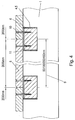
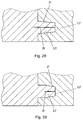
- Fig. 2 shows a mounting plate 6 in a groove receiving this 4.
- the side surfaces of the groove 4 have molded, elastic, wedge-shaped projections 11 (ribs) for centrally positioning and / or clamping fixing mounting plates 6 different width.
- a fire protection plate 8 or panel 8 'on On the space inside surface 7 of the Untersparrendämmplatte 1 is a fire protection plate 8 or panel 8 'on.
- the depth of the groove 4 is greater than the thickness of the slat 6. This embodiment is preferred for uneven / curved slats 6.
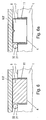
- Fig. 3 shows an embodiment of a groove 4 with a mounting batten 6, wherein the molded, elastic wedge-shaped projections 11 on the side surfaces of the groove 4 set straight, flat mounting slats 6 different width in the groove 4 centering and clamping.
- a fire protection plate 8 or panel 8 'on On the straight, flat mounting batten 6 is a fire protection plate 8 or panel 8 'on.
- Fig. 4 shows the central grid spacing 9 of the grooves 4.5 for receiving mounting battens 6 or square profile rails 6 'of 50 and / or 100 and / or 200 and / or 400 mm.
- a screw 10 standard fire protection panels 8 are fixed with a length of 2000 mm without shortening at their horizontal ends to the mounting slats 6.
- Fig. 5 shows a groove 4.5 with a lying in her mounting batten 6 and the elastic wedge-shaped or semicircular projections 11 on the side surfaces of the groove 4.5, which mounting plates 6 different width or square profile rails 6 'in the groove 4, 5 centered clamp.
- Fig. 5a shows another embodiment of the rib-shaped projections 11 on the side surfaces of the grooves 4, fifth
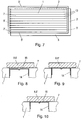
- Fig. 6 shows grooves 4.5 with straight, flat mounting slats 6 or square profile rails 6 'projecting beyond the space inside surface 7 of the Untersparzendämmplatte 1, which formed between the space inside surface 7 of the Untersparzendämmplatten 1 and the fire protection panels 8 or a panel 8', a free space 31 in which, for example, installations such as piping 32 can be accommodated.
- Fig. 6a shows this embodiment with a profile strip 6 'in place of a mounting batten.
- Fig. 7 shows the surface 7 of a Untersparrendämmplatte 1 with horizontally extending groove 2 and spring 3, with vertically extending groove 2 'and spring 3', molded grooves in the form of pairs of slots 13 for receiving the legs of rails 14 with a central grid spacing of 50 and / or 100 and / or 200 and / or 400 mm. At all abutting edges surfaces 5 'extend for sealing by means of adhesive 15 or sealing tape 15'.
- Fig. 8 In the execution of Fig. 8 is the rail 14 against the space inside surface 7 of the Untersparzendämmplatte 1, which forms the support surface for fire protection panels 8 or a clothing 8 ', recessed, so that there is a recess between the webs of the profile strip 14 and the plate 8.
- Fig. 9 is the web of the rail 14 on the surface 7 of, so that the web of the rail 14, the support surface for fire protection panels 8 or a panel 8 'forms.
- Fig. 10 Aligns the web of the rail 14 with the space inside surface 7 of the Untersparzendämmplatte 1 so that these and the rail 14 form a support surface for fire protection panels 8 or a panel 8 '.
- Fig. 11, 11a and 11b show profile rails 14 in U-, L-, or T-shape with smooth web.
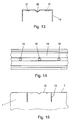
- Figs. 12, 12a and 12b show profile rails 14 with stiffening profiles 17 in the web and a V-profile 18 for receiving screw heads.
- Fig. 13 shows a rail 14 with a V-shaped profiling 18 for receiving screw heads.
- Fig. 14 shows a plan view of the rail 14 of Fig. 13 with prefabricated holes 19 for fasteners, such as mounting screws.
- Fig. 15 shows a Untersparrendämmplatte 1 in an embodiment for receiving profiled rails 14 with slots 13 in the space inside surface 7 and with a web of the rail 14 (not shown) corresponding profiled area 16 between the slots thirteenth
- Fig. 16 is an insulating Kunststoffbeilagsay 20 or rail 20 'provided in the V-shaped profiling 18 of a rail 14 for receiving screw heads.
- a sound-absorbing and / or intumescent coating 21 is provided on the interior surface of the profile rails 14.
- Fig. 18 shows how groove-shaped recesses horizontally 5 and vertically 5 "at the abutting edges of Untersparrendämmplatten 1 to a continuous, extending over all abutting edges level 5 'to grooves for the receptacles of mounting plates 6 or moldings 6' complement .
- an adhesive Also here are formed, elastic projections 11 on the side surfaces of the horizontal groove-shaped recesses 5 on the horizontal abutting edges of Untersparrendämmplatten 1 for centrally positioning and fixing of mounting slats 6 different width or square profile rails 6 'is provided.
- Fig. 20 shows in a sectional view parallel and transverse to the spring 3,3 'extending sealing lips 22 and resulting sealing chambers 23 on the side surfaces of the springs 3,3' in composite Untersparzendämmplatten first
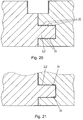
- a taper 24 is provided in the groove 2,2 'with the side surfaces approaching each other toward the bottom of the groove 2,2'.
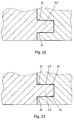
- the taper 23 of the groove 2,2 'and the widening 25 of the spring 3,3' can also be present in combination ( Fig. 24 ).
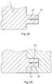
- Fig. 25 shows a spring 3, 3 'which is elastically deformed by clamping in a sub-dimensioned groove 2, 2' in the slot area 26.
- Fig. 26 It is shown how a spring 3,3 'by the taper 24 of the groove 2,2' in its slot portion 26 is elastically deformed.
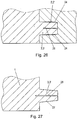
- Fig. 27 has the spring 3,3 'mutually inclined side surfaces 27 and a slot 26th
- Fig. 28 shows as by clamping the spring 3,3 'of Fig. 28 in the undersized, V-shaped groove 2,2 ', the spring 3,3' is elastically deformed in the slot area 26, the groove 2,2 'being tapered as a whole.
- Fig. 29 is an embodiment similar Fig. 28 shown, wherein the groove 2,2 'only in its groove bottom adjacent area (similar Fig. 22 ) is tapered.
- Fig. 30 shows the arrangement of elastic sealing tapes 28 at the abutting edges of the sub-spar insulating panels 1 or at the bottom of the groove 2,2 'or at the end faces of the spring 3,3'.
- Fig. 31 shows the bonding of the abutting edges of the Untersparrendämmplatten 1 and the adhesion to the bottom of the groove 2,2 'and the end face of the spring 3,3' by means of double-sided adhesive tapes 29 or adhesive 29 '.
- Fig. 32 In the side view of Fig. 32 is at the bottom of the horizontal groove 2 and on the horizontal end face of the vertical spring 3 'in parallel over portions extending from the bottom of the horizontal groove 2 in the horizontal surface of the vertical spring 3' and across the entire width of the horizontal groove 2 and across the entire horizontal width of the vertical spring 3 'extending, at least one molded sealing lip 30 or sealing wedge 30' is provided.
- Fig. 33 to Fig. 32 are at the bottom of the horizontal groove 2 and on the horizontal end face of the vertical spring 3 'in parallel over portions extending from the bottom of the horizontal groove 2 in the horizontal surface of the vertical spring 3' and across the entire width of the horizontal groove 2 and transverse over the entire horizontal width of the vertical spring 3 'extending, molded sealing lips 30 or sealing wedges 30' shown, wherein the spring 3 'may be formed with a slot 26.
- Fig. 34 is at the bottom of the vertical groove 2 'and on the vertical face of the horizontal spring 3 in parallel over portions extending from the bottom of the vertical groove 2' in the vertical surface of the horizontal spring 3 and across the entire width of the vertical groove 2 'and across the entire vertical width of the horizontal spring 3 extending, at least one molded sealing lip 30 or sealing wedge 30 'shown.
- Fig. 35 shows the top view Fig. 34 wherein the vertical end face of the horizontal spring 3 extends in parallel over portions extending from the bottom of the vertical groove 2 'into the vertical surface of the horizontal spring 3 and across the entire width of the vertical groove 2' and across the whole vertical width of the horizontal spring 3 extending, one or more of the spring 3 with slot 26 may be formed.
- Fig. 36 can be provided in the space inside surface 7 and / or stepped surface 5 'of a Untersparzendämmplatte 1 recesses 33,33' with deflection 34 'for receiving heating pipes / cooling tubes 34. Furthermore, parallel and / or transverse to the recesses 33,33 'arranged intoleitbleche /deleitbleche 35 or sautfolien / Kälteleitfolien 35', with horizontally extending groove 2 and spring 3, with vertically extending groove 2 'and spring 3', molded grooves 4, 5 for receiving mounting slats 6 or 4-edged profile rails 6 'with a central grid spacing of 50 and / or 100 and / or 200 and / or 400 mm and extending at all abutting edges surface 5' for sealing by means of adhesive tape 15 or sealing tape 15 'may be provided ,
- Fig. 37 shows on the space inside surface 7 of the Untersparzendämmplatte 1 a molded recess 33 with therein arranged heating pipe / cooling tube 34 and flat resting fire protection plate 8 or panel 8 '.
- Fig. 38 engages in the region of the space inside surface 7 of the Untersparzendämmplatte 1 befindliches heating pipe / cooling tube 34 partially in a molded-recess 33 'of the plate 1 and partially in applied plaster 36 a.
- Fig. 39 shows an embodiment of a Untersparrendämmplatte 1 having on its interior inside a Untersparzendämmplatte 1 with horizontally extending groove 2, and with a spring 3, with vertically extending groove 2 'and spring 3', molded grooves 4 for receiving mounting battens 6 or square profile rails 6 ' and with horizontally molded slots 13 for receiving rails 14 with a central grid spacing of 50 and / or 100 and / or 200 and / or 400 mm and extending at all abutting edges surface 5 'for sealing by means of adhesive tape 15 or sealing tape 15', the horizontal abutting edge groove 5 and the vertical abutting edge groove 5 ''.
- Fig. 40 shows how on the space inside 7 and / or space outside surface of the Untersparzendämmplatte 1 molded and numbered cutting marks 37 may be provided.
- In the space inside surfaces 7 of the insulation boards 1 grooves 4 are provided for receiving strips 6.
- On the strips 6 fire protection or cladding panels 8,8 'are attached.
- At the edges of the insulation boards 1 grooves 2 and springs 3 are provided, via which adjacent insulation boards 1 are positively connected with each other. The joints between adjacent insulating panels 1 are sealed.
- the insulation boards 1 have at the edges grooves 2,2 'and springs 3,3' for positive connection with other insulation boards 1, wherein at the edges of the insulation board 1 longitudinal recesses are provided in the region of the vertical abutting edges of adjacent insulation boards.
- 1 a vertical Stoßkantennut 5 "and in the region of the horizontal abutting edges of adjacent insulation boards 1 a horizontal Stoßkantennut 5 for receiving strips 6, 6 'form.
Landscapes
- Engineering & Computer Science (AREA)
- Architecture (AREA)
- Civil Engineering (AREA)
- Structural Engineering (AREA)
- Mechanical Engineering (AREA)
- Physics & Mathematics (AREA)
- Electromagnetism (AREA)
- Building Environments (AREA)
- Roof Covering Using Slabs Or Stiff Sheets (AREA)
Priority Applications (1)
| Application Number | Priority Date | Filing Date | Title |
|---|---|---|---|
| SI200731864A SI2674545T1 (sl) | 2006-02-14 | 2007-02-14 | Izolacija, ki obsega izolacijske plošče z utori in utornimi vodili vzdolž robov |
Applications Claiming Priority (2)
| Application Number | Priority Date | Filing Date | Title |
|---|---|---|---|
| AT0010706U AT9850U1 (de) | 2006-02-14 | 2006-02-14 | Untersparrendämmplatte |
| EP07450023A EP1818475A3 (de) | 2006-02-14 | 2007-02-14 | Insulation using insulation panels with tongue and groove edge connection |
Related Parent Applications (2)
| Application Number | Title | Priority Date | Filing Date |
|---|---|---|---|
| EP07450023.2 Division | 2007-02-14 | ||
| EP07450023A Division EP1818475A3 (de) | 2006-02-14 | 2007-02-14 | Insulation using insulation panels with tongue and groove edge connection |
Publications (3)
| Publication Number | Publication Date |
|---|---|
| EP2674545A2 EP2674545A2 (de) | 2013-12-18 |
| EP2674545A3 EP2674545A3 (de) | 2014-02-12 |
| EP2674545B1 true EP2674545B1 (de) | 2016-08-31 |
Family
ID=37964746
Family Applications (2)
| Application Number | Title | Priority Date | Filing Date |
|---|---|---|---|
| EP13003611.4A Active EP2674545B1 (de) | 2006-02-14 | 2007-02-14 | Dämmung aus Dämmplatten mit Nut-Feder-Randverbindungen |
| EP07450023A Withdrawn EP1818475A3 (de) | 2006-02-14 | 2007-02-14 | Insulation using insulation panels with tongue and groove edge connection |
Family Applications After (1)
| Application Number | Title | Priority Date | Filing Date |
|---|---|---|---|
| EP07450023A Withdrawn EP1818475A3 (de) | 2006-02-14 | 2007-02-14 | Insulation using insulation panels with tongue and groove edge connection |
Country Status (5)
| Country | Link |
|---|---|
| EP (2) | EP2674545B1 (pl) |
| AT (1) | AT9850U1 (pl) |
| HU (1) | HUE030709T2 (pl) |
| PL (1) | PL2674545T3 (pl) |
| SI (1) | SI2674545T1 (pl) |
Families Citing this family (2)
| Publication number | Priority date | Publication date | Assignee | Title |
|---|---|---|---|---|
| DE202010000245U1 (de) * | 2010-02-23 | 2010-06-24 | Hoppe, Christian | Schallabsorberelement zum Einbau in eine Brandschutzkonstruktion aus Brandschutzplatten |
| DE102020132333A1 (de) * | 2020-12-04 | 2022-06-09 | Bayerische Motoren Werke Aktiengesellschaft | Isolierwand für einen Kraftwagen sowie Kraftwagen mit einer Isolierwand |
Family Cites Families (13)
| Publication number | Priority date | Publication date | Assignee | Title |
|---|---|---|---|---|
| DE2552160A1 (de) * | 1975-11-20 | 1977-05-26 | Daemm & System Bau Gmbh | Wandschale zur herstellung von mantelbetonwaenden |
| DE2614529C3 (de) * | 1976-04-03 | 1979-10-31 | Roland 6953 Gundelsheim Bender | Isolierverkleidung für Räume |
| US4107892A (en) | 1977-07-27 | 1978-08-22 | Butler Manufacturing Company | Wall panel unit |
| US4522004A (en) * | 1983-06-16 | 1985-06-11 | Owens-Corning Fiberglas Corporation | Insulated wall construction |
| GB8724690D0 (en) * | 1987-10-21 | 1987-11-25 | Fixafoam Ltd | Roofing panels |
| DE19756949A1 (de) * | 1997-12-22 | 1999-06-24 | Aestuver Sued Bauplatten Gmbh | Verfahren zum Herstellen eines Fassadensystems |
| EP1096078A3 (de) * | 1999-10-28 | 2002-09-11 | Knauf Gesellschaft m.b.H. | Verfahren zum Verbinden von aneinander versetzten Bauplatten und Bauplatte zur Duchführung dieses Verfahrens |
| AT4083U1 (de) | 2000-02-03 | 2001-01-25 | Thermo Com Daemmsysteme Entwic | Dachaufbau |
| DE10120810A1 (de) * | 2000-04-28 | 2001-11-22 | Isobouw Daemmtechnik Gmbh | Dach |
| JP2002327506A (ja) * | 2001-04-27 | 2002-11-15 | Masuda Renga Kk | 建築用断熱パネル構造体 |
| DE20115423U1 (de) * | 2001-09-18 | 2001-12-13 | Rigips Gmbh | Verbunddämmelement |
| KR100520468B1 (ko) * | 2003-06-16 | 2005-10-11 | 곽문근 | 폐고무분말과 유기성 슬러지를 원료로 한 경량단열 층간소음방지 패널의 제조방법 및 이를 이용한 층간 바닥구조 |
| NO20052599D0 (no) | 2005-05-30 | 2005-05-30 | Ti Marine Contracting | Process and system for thermal insulation of cryogenic containers and tanks. |
-
2006
- 2006-02-14 AT AT0010706U patent/AT9850U1/de not_active IP Right Cessation
-
2007
- 2007-02-14 HU HUE13003611A patent/HUE030709T2/en unknown
- 2007-02-14 SI SI200731864A patent/SI2674545T1/sl unknown
- 2007-02-14 EP EP13003611.4A patent/EP2674545B1/de active Active
- 2007-02-14 PL PL13003611T patent/PL2674545T3/pl unknown
- 2007-02-14 EP EP07450023A patent/EP1818475A3/de not_active Withdrawn
Also Published As
| Publication number | Publication date |
|---|---|
| AT9850U1 (de) | 2008-04-15 |
| SI2674545T1 (sl) | 2016-12-30 |
| EP1818475A2 (de) | 2007-08-15 |
| EP1818475A3 (de) | 2012-05-02 |
| EP2674545A2 (de) | 2013-12-18 |
| HUE030709T2 (en) | 2017-05-29 |
| EP2674545A3 (de) | 2014-02-12 |
| PL2674545T3 (pl) | 2017-03-31 |
Similar Documents
| Publication | Publication Date | Title |
|---|---|---|
| DE2030482A1 (de) | Zusammengesetzte Platte fur Ge baude | |
| DE2810517A1 (de) | Flug- und dichtvorrichtung | |
| EP0921252A2 (de) | Befestigungselement zur Abstandsbefestigung von Latten, Profilen, Platten oder dergleichen an einem festen Untergrund, Hilfsvorrichtung zum Bohren von Löchern in einem Untergrund zum Einsetzen der Befestigungselemente sowie Verfahren zur Abstandsbefestigung unter Einsatz eines solchen Befestigungselementes | |
| DE202007014565U1 (de) | Wärmedämmverbundsystem | |
| EP0984114B1 (de) | Zweischaliges Dachsystem | |
| EP2674545B1 (de) | Dämmung aus Dämmplatten mit Nut-Feder-Randverbindungen | |
| DE3132152A1 (de) | Daemmverbundschicht fuer steildaecher | |
| WO2011063938A2 (de) | Wärmedämmsystem für eine gebäudehülle | |
| EP0795659A1 (de) | Dachkonstruktion | |
| EP0969159B1 (de) | Gebäudehülle | |
| AT410457B (de) | Vorrichtung zum befestigen von hinterlüfteten fassadenplatten | |
| DE2102537A1 (de) | Plattenförmiges Bauelement aus Harlschaumkunststoff o.dgl. mit falzartigen Rändern zur Wärmeisolierung von Dach- und Wandflächen | |
| DE4101234A1 (de) | Unterdach-waermedaemmelement | |
| WO2010051999A2 (de) | Integriertes dachsystem, befestigung von einlegeprofilen auf sandwichpaneelen mit hinterschnitt-nuten | |
| DE19815202A1 (de) | Dämmplatte zur Verwendung an Außenfassaden von Häusern | |
| AT3882U1 (de) | Steildachaufsparren- und fassadendämmsystem, hinterlüftete thermoisolierende dacheindeckung und -fassadensystem mit integrierten fassadenplatten | |
| DE19826137A1 (de) | Dämmelement zur Wärme- und/oder Schalldämmung einer Gebäudedachkonstruktion | |
| DE10120810A1 (de) | Dach | |
| DE10228002A1 (de) | Gebäudeelement und Dämmstoffelement für ein Gebäudeelement | |
| EP0778377B1 (de) | Winddichter Dachaufbau und Montageverfahren zu seiner Herstellung | |
| DE3933108A1 (de) | Waermedaemmplatte | |
| DE19618587C2 (de) | Verfahren zum Errichten einer Unterkonstruktion und dafür geeignetes Dachausbauelement | |
| EP3115526A1 (de) | Fugenabdichtung zwischen dämmelementen zur gebäudedämmung | |
| DE3407069A1 (de) | Waermedaemmung fuer welldaecher, insbesondere fuer asbestzementdaecher und verfahren zum aufbringen derselben | |
| WO2006027180A1 (de) | Vorrichtung zur befestigung von dämmstoffelementen auf einer dachunterkonstruktion und gebäudedach |
Legal Events
| Date | Code | Title | Description |
|---|---|---|---|
| PUAI | Public reference made under article 153(3) epc to a published international application that has entered the european phase |
Free format text: ORIGINAL CODE: 0009012 |
|
| AC | Divisional application: reference to earlier application |
Ref document number: 1818475 Country of ref document: EP Kind code of ref document: P |
|
| AK | Designated contracting states |
Kind code of ref document: A2 Designated state(s): AT BE BG CH CY CZ DE DK EE ES FI FR GB GR HU IE IS IT LI LT LU LV MC NL PL PT RO SE SI SK TR |
|
| AX | Request for extension of the european patent |
Extension state: BA |
|
| PUAL | Search report despatched |
Free format text: ORIGINAL CODE: 0009013 |
|
| AK | Designated contracting states |
Kind code of ref document: A3 Designated state(s): AT BE BG CH CY CZ DE DK EE ES FI FR GB GR HU IE IS IT LI LT LU LV MC NL PL PT RO SE SI SK TR |
|
| AX | Request for extension of the european patent |
Extension state: BA |
|
| RIC1 | Information provided on ipc code assigned before grant |
Ipc: E04D 13/16 20060101AFI20140107BHEP Ipc: E04B 1/94 20060101ALI20140107BHEP Ipc: E04B 1/61 20060101ALI20140107BHEP |
|
| 17P | Request for examination filed |
Effective date: 20140731 |
|
| RAX | Requested extension states of the european patent have changed |
Extension state: BA Payment date: 20140731 |
|
| RBV | Designated contracting states (corrected) |
Designated state(s): AT BE BG CH CY CZ DE DK EE ES FI FR GB GR HU IE IS IT LI LT LU LV MC NL PL PT RO SE SI SK TR |
|
| 17Q | First examination report despatched |
Effective date: 20150907 |
|
| GRAP | Despatch of communication of intention to grant a patent |
Free format text: ORIGINAL CODE: EPIDOSNIGR1 |
|
| INTG | Intention to grant announced |
Effective date: 20160413 |
|
| GRAS | Grant fee paid |
Free format text: ORIGINAL CODE: EPIDOSNIGR3 |
|
| GRAA | (expected) grant |
Free format text: ORIGINAL CODE: 0009210 |
|
| AC | Divisional application: reference to earlier application |
Ref document number: 1818475 Country of ref document: EP Kind code of ref document: P |
|
| AK | Designated contracting states |
Kind code of ref document: B1 Designated state(s): AT BE BG CH CY CZ DE DK EE ES FI FR GB GR HU IE IS IT LI LT LU LV MC NL PL PT RO SE SI SK TR |
|
| AX | Request for extension of the european patent |
Extension state: BA |
|
| REG | Reference to a national code |
Ref country code: CH Ref legal event code: EP Ref country code: GB Ref legal event code: FG4D Free format text: NOT ENGLISH |
|
| REG | Reference to a national code |
Ref country code: IE Ref legal event code: FG4D Free format text: LANGUAGE OF EP DOCUMENT: GERMAN |
|
| REG | Reference to a national code |
Ref country code: AT Ref legal event code: REF Ref document number: 825120 Country of ref document: AT Kind code of ref document: T Effective date: 20161015 |
|
| REG | Reference to a national code |
Ref country code: DE Ref legal event code: R096 Ref document number: 502007015080 Country of ref document: DE |
|
| REG | Reference to a national code |
Ref country code: CH Ref legal event code: NV Representative=s name: RENTSCH PARTNER AG, CH |
|
| REG | Reference to a national code |
Ref country code: NL Ref legal event code: FP |
|
| REG | Reference to a national code |
Ref country code: CH Ref legal event code: PCOW Free format text: NEW ADDRESS: FUERFANGGASSE 1, 1190 WIEN (AT) |
|
| REG | Reference to a national code |
Ref country code: LT Ref legal event code: MG4D |
|
| RAP2 | Party data changed (patent owner data changed or rights of a patent transferred) |
Owner name: TIEFENTHALER, MICHAEL |
|
| RIN2 | Information on inventor provided after grant (corrected) |
Inventor name: TIEFENTHALER, MICHAEL |
|
| PG25 | Lapsed in a contracting state [announced via postgrant information from national office to epo] |
Ref country code: FI Free format text: LAPSE BECAUSE OF FAILURE TO SUBMIT A TRANSLATION OF THE DESCRIPTION OR TO PAY THE FEE WITHIN THE PRESCRIBED TIME-LIMIT Effective date: 20160831 Ref country code: LT Free format text: LAPSE BECAUSE OF FAILURE TO SUBMIT A TRANSLATION OF THE DESCRIPTION OR TO PAY THE FEE WITHIN THE PRESCRIBED TIME-LIMIT Effective date: 20160831 |
|
| REG | Reference to a national code |
Ref country code: FR Ref legal event code: PLFP Year of fee payment: 11 |
|
| PG25 | Lapsed in a contracting state [announced via postgrant information from national office to epo] |
Ref country code: ES Free format text: LAPSE BECAUSE OF FAILURE TO SUBMIT A TRANSLATION OF THE DESCRIPTION OR TO PAY THE FEE WITHIN THE PRESCRIBED TIME-LIMIT Effective date: 20160831 Ref country code: SE Free format text: LAPSE BECAUSE OF FAILURE TO SUBMIT A TRANSLATION OF THE DESCRIPTION OR TO PAY THE FEE WITHIN THE PRESCRIBED TIME-LIMIT Effective date: 20160831 Ref country code: LV Free format text: LAPSE BECAUSE OF FAILURE TO SUBMIT A TRANSLATION OF THE DESCRIPTION OR TO PAY THE FEE WITHIN THE PRESCRIBED TIME-LIMIT Effective date: 20160831 Ref country code: GR Free format text: LAPSE BECAUSE OF FAILURE TO SUBMIT A TRANSLATION OF THE DESCRIPTION OR TO PAY THE FEE WITHIN THE PRESCRIBED TIME-LIMIT Effective date: 20161201 |
|
| PG25 | Lapsed in a contracting state [announced via postgrant information from national office to epo] |
Ref country code: RO Free format text: LAPSE BECAUSE OF FAILURE TO SUBMIT A TRANSLATION OF THE DESCRIPTION OR TO PAY THE FEE WITHIN THE PRESCRIBED TIME-LIMIT Effective date: 20160831 Ref country code: EE Free format text: LAPSE BECAUSE OF FAILURE TO SUBMIT A TRANSLATION OF THE DESCRIPTION OR TO PAY THE FEE WITHIN THE PRESCRIBED TIME-LIMIT Effective date: 20160831 |
|
| REG | Reference to a national code |
Ref country code: HU Ref legal event code: AG4A Ref document number: E030709 Country of ref document: HU |
|
| PG25 | Lapsed in a contracting state [announced via postgrant information from national office to epo] |
Ref country code: BG Free format text: LAPSE BECAUSE OF FAILURE TO SUBMIT A TRANSLATION OF THE DESCRIPTION OR TO PAY THE FEE WITHIN THE PRESCRIBED TIME-LIMIT Effective date: 20161130 Ref country code: PT Free format text: LAPSE BECAUSE OF FAILURE TO SUBMIT A TRANSLATION OF THE DESCRIPTION OR TO PAY THE FEE WITHIN THE PRESCRIBED TIME-LIMIT Effective date: 20170102 Ref country code: DK Free format text: LAPSE BECAUSE OF FAILURE TO SUBMIT A TRANSLATION OF THE DESCRIPTION OR TO PAY THE FEE WITHIN THE PRESCRIBED TIME-LIMIT Effective date: 20160831 |
|
| REG | Reference to a national code |
Ref country code: DE Ref legal event code: R097 Ref document number: 502007015080 Country of ref document: DE |
|
| REG | Reference to a national code |
Ref country code: FR Ref legal event code: CA Effective date: 20170503 |
|
| PG25 | Lapsed in a contracting state [announced via postgrant information from national office to epo] |
Ref country code: IT Free format text: LAPSE BECAUSE OF FAILURE TO SUBMIT A TRANSLATION OF THE DESCRIPTION OR TO PAY THE FEE WITHIN THE PRESCRIBED TIME-LIMIT Effective date: 20160831 |
|
| REG | Reference to a national code |
Ref country code: SK Ref legal event code: T3 Ref document number: E 23025 Country of ref document: SK |
|
| PLBE | No opposition filed within time limit |
Free format text: ORIGINAL CODE: 0009261 |
|
| STAA | Information on the status of an ep patent application or granted ep patent |
Free format text: STATUS: NO OPPOSITION FILED WITHIN TIME LIMIT |
|
| 26N | No opposition filed |
Effective date: 20170601 |
|
| PG25 | Lapsed in a contracting state [announced via postgrant information from national office to epo] |
Ref country code: MC Free format text: LAPSE BECAUSE OF FAILURE TO SUBMIT A TRANSLATION OF THE DESCRIPTION OR TO PAY THE FEE WITHIN THE PRESCRIBED TIME-LIMIT Effective date: 20160831 |
|
| REG | Reference to a national code |
Ref country code: CH Ref legal event code: PCAR Free format text: NEW ADDRESS: BELLERIVESTRASSE 203 POSTFACH, 8034 ZUERICH (CH) |
|
| REG | Reference to a national code |
Ref country code: FR Ref legal event code: PLFP Year of fee payment: 12 |
|
| PG25 | Lapsed in a contracting state [announced via postgrant information from national office to epo] |
Ref country code: CY Free format text: LAPSE BECAUSE OF NON-PAYMENT OF DUE FEES Effective date: 20160831 |
|
| PG25 | Lapsed in a contracting state [announced via postgrant information from national office to epo] |
Ref country code: TR Free format text: LAPSE BECAUSE OF FAILURE TO SUBMIT A TRANSLATION OF THE DESCRIPTION OR TO PAY THE FEE WITHIN THE PRESCRIBED TIME-LIMIT Effective date: 20160831 |
|
| PG25 | Lapsed in a contracting state [announced via postgrant information from national office to epo] |
Ref country code: IS Free format text: LAPSE BECAUSE OF FAILURE TO SUBMIT A TRANSLATION OF THE DESCRIPTION OR TO PAY THE FEE WITHIN THE PRESCRIBED TIME-LIMIT Effective date: 20161231 |
|
| PGFP | Annual fee paid to national office [announced via postgrant information from national office to epo] |
Ref country code: FR Payment date: 20230221 Year of fee payment: 17 |
|
| PGFP | Annual fee paid to national office [announced via postgrant information from national office to epo] |
Ref country code: PL Payment date: 20230203 Year of fee payment: 17 Ref country code: BE Payment date: 20230216 Year of fee payment: 17 |
|
| P01 | Opt-out of the competence of the unified patent court (upc) registered |
Effective date: 20230508 |
|
| PGFP | Annual fee paid to national office [announced via postgrant information from national office to epo] |
Ref country code: LU Payment date: 20240220 Year of fee payment: 18 |
|
| PGFP | Annual fee paid to national office [announced via postgrant information from national office to epo] |
Ref country code: NL Payment date: 20240219 Year of fee payment: 18 Ref country code: IE Payment date: 20240219 Year of fee payment: 18 |
|
| PGFP | Annual fee paid to national office [announced via postgrant information from national office to epo] |
Ref country code: AT Payment date: 20240228 Year of fee payment: 18 |
|
| PGFP | Annual fee paid to national office [announced via postgrant information from national office to epo] |
Ref country code: HU Payment date: 20240222 Year of fee payment: 18 Ref country code: DE Payment date: 20240219 Year of fee payment: 18 Ref country code: CZ Payment date: 20240206 Year of fee payment: 18 Ref country code: CH Payment date: 20240301 Year of fee payment: 18 Ref country code: SK Payment date: 20240205 Year of fee payment: 18 Ref country code: GB Payment date: 20240219 Year of fee payment: 18 |
|
| PGFP | Annual fee paid to national office [announced via postgrant information from national office to epo] |
Ref country code: SI Payment date: 20240201 Year of fee payment: 18 |