EP2674545B1 - Insulation comprising insulating panels with groove and tongue joints along the edges - Google Patents
Insulation comprising insulating panels with groove and tongue joints along the edges Download PDFInfo
- Publication number
- EP2674545B1 EP2674545B1 EP13003611.4A EP13003611A EP2674545B1 EP 2674545 B1 EP2674545 B1 EP 2674545B1 EP 13003611 A EP13003611 A EP 13003611A EP 2674545 B1 EP2674545 B1 EP 2674545B1
- Authority
- EP
- European Patent Office
- Prior art keywords
- groove
- spring
- horizontal
- insulating panel
- vertical
- Prior art date
- Legal status (The legal status is an assumption and is not a legal conclusion. Google has not performed a legal analysis and makes no representation as to the accuracy of the status listed.)
- Active
Links
- 238000009413 insulation Methods 0.000 title claims description 48
- 238000007789 sealing Methods 0.000 claims description 73
- 238000001816 cooling Methods 0.000 claims description 24
- 238000010438 heat treatment Methods 0.000 claims description 24
- 239000000853 adhesive Substances 0.000 claims description 14
- 230000001070 adhesive effect Effects 0.000 claims description 13
- 238000009434 installation Methods 0.000 claims description 10
- 230000000873 masking effect Effects 0.000 claims description 7
- 238000000465 moulding Methods 0.000 claims description 7
- 239000002390 adhesive tape Substances 0.000 claims description 6
- 238000004026 adhesive bonding Methods 0.000 claims description 5
- 230000015572 biosynthetic process Effects 0.000 description 8
- 238000005755 formation reaction Methods 0.000 description 8
- 238000005253 cladding Methods 0.000 description 6
- 239000011505 plaster Substances 0.000 description 5
- 238000010276 construction Methods 0.000 description 4
- 239000011888 foil Substances 0.000 description 4
- 239000002184 metal Substances 0.000 description 4
- XLYOFNOQVPJJNP-UHFFFAOYSA-N water Chemical compound O XLYOFNOQVPJJNP-UHFFFAOYSA-N 0.000 description 4
- 230000004888 barrier function Effects 0.000 description 3
- 239000011248 coating agent Substances 0.000 description 3
- 238000000576 coating method Methods 0.000 description 3
- 239000011810 insulating material Substances 0.000 description 3
- 239000004033 plastic Substances 0.000 description 3
- 238000004904 shortening Methods 0.000 description 3
- 230000001464 adherent effect Effects 0.000 description 2
- 230000006835 compression Effects 0.000 description 2
- 238000007906 compression Methods 0.000 description 2
- 238000009833 condensation Methods 0.000 description 2
- 230000005494 condensation Effects 0.000 description 2
- 238000005520 cutting process Methods 0.000 description 2
- 238000003780 insertion Methods 0.000 description 2
- 230000037431 insertion Effects 0.000 description 2
- 239000011490 mineral wool Substances 0.000 description 2
- 230000000295 complement effect Effects 0.000 description 1
- 239000002131 composite material Substances 0.000 description 1
- 230000001419 dependent effect Effects 0.000 description 1
- 238000009792 diffusion process Methods 0.000 description 1
- 229920006248 expandable polystyrene Polymers 0.000 description 1
- 239000003063 flame retardant Substances 0.000 description 1
- 238000009415 formwork Methods 0.000 description 1
- 239000012774 insulation material Substances 0.000 description 1
- 239000000463 material Substances 0.000 description 1
- 238000005457 optimization Methods 0.000 description 1
- 230000035699 permeability Effects 0.000 description 1
- 239000002984 plastic foam Substances 0.000 description 1
- 230000003716 rejuvenation Effects 0.000 description 1
- 230000000284 resting effect Effects 0.000 description 1
- 230000000630 rising effect Effects 0.000 description 1
- 238000007493 shaping process Methods 0.000 description 1
- 239000002023 wood Substances 0.000 description 1
Images


Classifications
-
- E—FIXED CONSTRUCTIONS
- E04—BUILDING
- E04D—ROOF COVERINGS; SKY-LIGHTS; GUTTERS; ROOF-WORKING TOOLS
- E04D13/00—Special arrangements or devices in connection with roof coverings; Protection against birds; Roof drainage; Sky-lights
- E04D13/16—Insulating devices or arrangements in so far as the roof covering is concerned, e.g. characterised by the material or composition of the roof insulating material or its integration in the roof structure
- E04D13/1606—Insulation of the roof covering characterised by its integration in the roof structure
- E04D13/1612—Insulation of the roof covering characterised by its integration in the roof structure the roof structure comprising a supporting framework of roof purlins or rafters
- E04D13/1637—Insulation of the roof covering characterised by its integration in the roof structure the roof structure comprising a supporting framework of roof purlins or rafters the roof purlins or rafters being mainly insulated from the interior, e.g. the insulating material being fixed under or suspended from the supporting framework
-
- E—FIXED CONSTRUCTIONS
- E04—BUILDING
- E04B—GENERAL BUILDING CONSTRUCTIONS; WALLS, e.g. PARTITIONS; ROOFS; FLOORS; CEILINGS; INSULATION OR OTHER PROTECTION OF BUILDINGS
- E04B1/00—Constructions in general; Structures which are not restricted either to walls, e.g. partitions, or floors or ceilings or roofs
- E04B1/62—Insulation or other protection; Elements or use of specified material therefor
- E04B1/92—Protection against other undesired influences or dangers
- E04B1/94—Protection against other undesired influences or dangers against fire
- E04B1/941—Building elements specially adapted therefor
- E04B1/942—Building elements specially adapted therefor slab-shaped
-
- E—FIXED CONSTRUCTIONS
- E04—BUILDING
- E04D—ROOF COVERINGS; SKY-LIGHTS; GUTTERS; ROOF-WORKING TOOLS
- E04D3/00—Roof covering by making use of flat or curved slabs or stiff sheets
- E04D3/36—Connecting; Fastening
- E04D3/3601—Connecting; Fastening of roof covering supported by the roof structure with interposition of a insulating layer
- E04D3/3602—The fastening means comprising elongated profiles installed in or on the insulation layer
-
- E—FIXED CONSTRUCTIONS
- E04—BUILDING
- E04B—GENERAL BUILDING CONSTRUCTIONS; WALLS, e.g. PARTITIONS; ROOFS; FLOORS; CEILINGS; INSULATION OR OTHER PROTECTION OF BUILDINGS
- E04B1/00—Constructions in general; Structures which are not restricted either to walls, e.g. partitions, or floors or ceilings or roofs
- E04B1/38—Connections for building structures in general
- E04B1/61—Connections for building structures in general of slab-shaped building elements with each other
- E04B1/6108—Connections for building structures in general of slab-shaped building elements with each other the frontal surfaces of the slabs connected together
- E04B1/612—Connections for building structures in general of slab-shaped building elements with each other the frontal surfaces of the slabs connected together by means between frontal surfaces
- E04B1/6125—Connections for building structures in general of slab-shaped building elements with each other the frontal surfaces of the slabs connected together by means between frontal surfaces with protrusions on the one frontal surface co-operating with recesses in the other frontal surface
Definitions
- the invention relates to an insulating board for insulation, preferably rectangular insulation board, in particular Untersparzendämmplatte, wherein the insulation board in one of its large areas has at least one groove for receiving strips and at their edges grooves and springs for positive connection with other insulation boards.
- the known Vollsparrendämmungen be designed so that between the rafters of the pitched roof directly under the roof formwork insulation (mineral wool, rock wool or plastic foam insulation boards) is attached. Thereafter, a construction battens (mostly made of wooden slats) is applied to the roof inside of the rafters. Between the slats of the construction battens a second layer of insulating material is introduced. Finally, a vapor barrier (foil) is attached to the construction battens, and the battens (mostly made of wood) are fastened under a covering to assemble fire protection boards.
- Another disadvantage of the known insulation is the risk of moisture formation in the insulating material by condensation of water vapor, because moist, warm room air cools when flowing below the dew point and condenses water vapor. As a result of possible leaks in the vapor barrier or vapor barrier, moisture accumulates in the insulation material.
- a disadvantage of these Untersparrendämmplatten is that the depth of the mounting slats receiving grooves usually corresponds to the height of the mounting battens, so that the mounting battens with the room-side surface of the insulation elements in alignment. Since wooden slats are usually used as mounting slats and they are not straight in the normal case, there is the disadvantage that uneven mounting slats protrude beyond the space inside surface of the insulation elements in the interior of the room. If the installation of the fire protection panels is carried out on uneven roof battens, the desired, even and flat surface of a room interior panel can not be produced.
- the width of the grooves receiving the mounting slats corresponds to the standard dimension of the mounting slats (wooden roof slats).
- mounting slats wooden roof slats
- which have only a slight excess in their width can not be inserted into the grooves provided for receiving the same.
- the mounting battens wooden roof battens
- have an undersize a central alignment in the grooves for the correct attachment of two fire protection plates, with the same bearing surface on the mounting battens at the abutting edges, is very difficult.
- The, preferably made of foamed polystyrene, known Untersparzendämmplatten are provided at their abutting edges with clamping, single or double tongue and groove formations.
- a disadvantage of this clamped running tongue and groove formations is that the insulation panels can be very difficult to assemble due to the high frictional resistance of the insulating material and the large clamping surface of the tongue and groove formation.
- Another disadvantage of this clamping, one or two-fold groove and Federausformung is that in the assembled state an air permeability in the area of T or Buchwinkanten the tongue and groove shape is given.
- the invention has for its object to provide an insulation board and an insulation of the type mentioned, which allows easy installation and provides a reliable insulation.
- longitudinal recesses are provided on the edges of the insulating board, which form a vertical abutting edge groove in the region of the vertical abutting edges of adjacent insulating boards and a horizontal abutting edge groove for receiving strips in the region of the horizontal abutting edges of adjacent insulating boards.
- an insulation is provided in which Untersparrendämmplatten be used, which have the advantage that the slats do not protrude beyond the space inside surface of the Untersparzendämmplatte even when not straight or flat mounting slats.
- mounting battens or rails can be adapted to the different lengths of fire protection boards.
- the invention provides a thermal insulation, which uses a heat bridge-free Untersparzendämmplatte for the pitched roof and ceiling area, in which by a preferred training in tongue and groove area by clamping or gluing in the region of the abutting edges between adjacent insulation boards a wind and steam convection-dense layer is given.
- a wind and steam convection-dense layer is given.
- the depth of the mounting slats receiving groove exceeds the height of the mounting slats, so that even when using curved mounting slats only the flat, interior space surface of the Untersparrendämmplatte forms the support surface for fire protection panels or other panel, since the depth the groove exceeds the dimension of the mounting slats plus the extent of their deflection.
- the groove can also be designed so that the depth of the groove is less than the height of the mounting slats, so that only the mounting slats form the support surface for fire protection panels or other cladding.
- the space between the (sub-rafter) insulation boards and fire protection boards is advantageous in case of fire because heat from the fire boards can not be transferred directly to the insulation boards.
- the space inside surface of Untersparrendämmplatten can be provided with a plurality of recesses in the central grid spacing of 50 and / or 100 and / or 200 and / or 400 mm for receiving mounting battens, four-sided rails or other rail.
- the mounting slats, square profile rails or rails can be positioned at the horizontal end of fire protection boards with a length of 2000 mm for their installation.
- the distance between the recesses for receiving the mounting slats, square rails or rails by their central grid spacing correspond to the dimensions of fire protection boards, so that they can be screwed at their horizontal ends without shortening and editing the mounting slats, four-sided rails or rails.
- This pitch (eg 200mm) allows to easily maintain the location of the attachment points (at least 100mm within the edge of the fire protection panel) for fixing fire protection panels.
- the recesses for receiving mounting slats are designed so that even mounting slats which under the standard width of mounting slats (wooden slats) or exceed centered in the groove for receiving mounting slats are positioned and remain adherent to the final mounting screw in its installed position , so that a "one-man assembly" is possible.
- the width of the groove for receiving mounting battens is greater than the standard dimension of the width of mounting battens (wooden roof battens).
- wedge-shaped, elastic projections be formed on both side surfaces of the groove.
- the distance between the at the plane of the insulation boards perpendicular side surfaces of the groove opposite, wedge-shaped projections from each other is preferably smaller than the standard size of the width of mounting battens (wooden roof slats), whereby when inserting the mounting slats in the grooves a central positioning and clamping fixing the mounting slats takes place in the groove by the elastic, wedge-shaped projections on the side surfaces of the groove.
- wedge-shaped projections serving for the central positioning and clamping of the mounting slats can be formed integrally, horizontally or vertically, continuously or only over partial areas, opposite or offset, on the (mutually facing) side surfaces of the groove for receiving mounting slats.
- the wedge-shaped, elastic projections which serve for the central positioning and / or clamping fixing of the mounting slats can also be designed semicircular or in any other desired form.
- the elastic projections described above may optionally also be formed only on a side surface of grooves.
- the depth of the groove on the space inside surface of Untersparrendämmplatten may be arbitrary, so that the mounting slats or square profile rails beyond the space inside surface of the Untersparrendämmplatten out into the room interior to between the space inside surface of Untersparzendämmplatten and To provide the fire protection panels or cladding an installation space for piping.
- Elastic projections for clamping fixing the mounting slats or four-sided rails on the side surfaces of the groove can also, as described above, be formed only over portions of the height of the mounting slats or four-sided rails receiving groove.
- Markings in the central grid spacing of 50 and / or 100 and / or 200 and / or 400 mm can also be applied or integrally formed on the space inside surface of the sub-rafter insulation panels in order to avoid time-consuming measuring of the distances between mounting slats to be mounted horizontally, quadrangular profile rails or mounting boards , provided on grooves for receiving or partially receiving mounting slats or four-edged rails can be dispensed with.
- the space inside surface of Untersparrendämmplatte in an exemplary embodiment configured such that the grooves are formed as horizontally extending, slot-like grooves (recesses) in the space inside surface of the Untersparzendämmplatten, in which Legs of rails are inserted.
- the legs of the rails and gegentechnische recesses on the space inside surface of Untersparrendämmplatte can also be designed such that the rails remain self-adhesive to the final assembly in the Untersparrendämmplatten.
- the rails for attaching the Untersparrendämmplatten to rafters or ceiling pliers on the one hand and fire protection boards or clothing on the other hand can be designed as U-profile strips, L-profile strips, T-profile strips, smooth with any stiffening profiles or smooth without profile in their webs ,
- the profile rails for attaching fire protection panels or a cladding on the interior side of the Untersparrendämmplatten may be made of metal, plastic or any other suitable material for this application.
- a continuous, or only in the area of holes for fastening means an opposite profiling according to the size and shape of a head (eg., Screw head) and provide prefabricated holes for the screw, whereby a flat support of the Fire protection panels or cladding is guaranteed on the rails and the rails must not be pre-drilled when screwing to rafters or ceiling pliers.
- a head eg., Screw head
- insulating plastic shims may be attached to the prefabricated holes for mounting screw. This function can also be taken over by a continuous, profiled and perforated plastic rail.
- the rail is designed such that it forms the bearing surface for the fire protection boards or clothing, a coating on the interior surface or plate-side surface of the rails can be applied to sound optimization.
- the profile rail can be provided with a fire-retardant (for example, foaming-up) coating on its interior surface.
- a fire-retardant for example, foaming-up
- the space inside surface of Untersparrendämmplatten can also be designed such that horizontally extending grooves for receiving mounting slats and horizontally extending slots (slot-like grooves) for receiving the legs of rails in the central grid spacing of 50 and / or 100 and / or 200 and / or 400mm are formed.
- the sealing of the insulating surface can be made by masking the abutting edges of adjacent Untersparzendämmplatten by means of adhesive or sealing tape.
- recesses are provided on both vertical and two horizontal abutting edges of Untersparrendämmplatten, at least the height of the groove for receiving mounting slats, four-sided rails or the height of slots for receiving the legs of rails and half the width of the adhesive or sealing tapes to be provided corresponds, whereby horizontally and vertically a continuous, planar plane for masking the abutting edges of adjacent Untersparzendämmplatten is formed by means of adhesive or sealing tape.
- this groove-shaped recess for masking the abutting edges of adjoining Untersparzendämmplatten be dimensioned such that this Stoßkantennut corresponds in its entire width and height of a groove for receiving mounting slats as described above or square rails and serves to accommodate them.
- elastic moldings for central positioning and clamping fixing of mounting slats or four-sided rails can be formed as previously described.
- the elastic projections can optionally also be formed only on one side surface of the abutting edge groove.
- the sealing in the region of the tongue and groove formation in the horizontal and vertical abutting edge region of Untersparrendämmplatten is inventively achieved in an exemplary embodiment in that the spring is made narrower than the inner dimension of the side surfaces of the groove. It is preferred if on the spring on the rising surfaces on both sides parallel and transverse to the spring extending sealing lips are formed.
- the spring with the sealing lips formed on both sides on the surfaces is dimensioned larger than the internal dimension of the side surfaces of the groove, so that the spring with the sealing lips formed thereon can be inserted into the groove by clamping.
- the Untersparzendämmplatten in this embodiment the invention in the abutting edge region during assembly with substantially low resistance inserted into one another.
- the parallel and transverse to the side surfaces of the spring extending sealing lips have the advantage of forming a plurality of sealing chambers. If sealing lips are partially damaged prior to collapsing adjacent Untersparrendämmplatten and thus the sealing function on a sealing chamber no longer be given, the sealing function of adjacent sealing chambers is maintained and thus the overall tightness in the abutting edge region of Untersparrendämmplatten ensured.
- the sealing in the region of the tongue and groove formation in the horizontal and vertical abutting edge region of Untersparrendämmplatten can according to the invention, for example, be achieved in that the width of the spring is smaller than the width of the inner dimension of the groove.
- a taper of the groove is formed, which is narrower than the width of the spring.
- the spring is inserted by clamping when inserted into the groove. This rejuvenation can be on one or both Side surfaces of the groove may be provided.
- this form of sealing can also be embodied, for example, such that the widening of the tongue towards its root has a widening that exceeds the inner dimension of the groove, so that the groove can be slid onto the spring in a clamping manner.
- This broadening in the region of the root of the spring can be formed on one or both sides of the spring.
- This sealing variant can also be made in combination, so that a taper of the groove to its base and a broadening of the spring are formed to its root.
- a sealing of the Untersparrendämmplatten in the abutting edge region can also be prepared according to the invention by the fact that in the spring one or more substantially parallel to their upstanding side surfaces extending / e / s slot / e is / are formed, which / r over any range of the height of the spring or extends into the region of the Untersparrendämm stresses inside.
- the spring is wider than the groove.
- the parts separated by the slit (s) of the spring are resiliently pressed against the lateral surfaces of the groove, whereby an elastic, reliable sealing of the tongue and groove joint can be produced.
- This elastic compression of the slotted spring can also be brought about and / or reinforced by tapering on the upstanding side surfaces at the bottom of the groove.
- the tongue and groove connection with slotted spring is substantially V-shaped.
- the spring can be inserted over a large area without frictional resistance in the groove. Only in the last portion of the insertion of the spring into the groove, the clamping of the elastic, separated by the / slit / e parts of the spring is effective, whereby the side surfaces of the spring are pressed against the side surfaces of the groove, which towards its bottom to the Width or portions of the width of the slot in the spring is narrower.
- This form of sealing can also be designed as a combined, parallel and V-shaped, opposite groove and slotted spring connection be.
- the sealing in the abutting edge region of adjoining Untersparrendämmplatten can be made according to the invention also using elastic sealing strips.
- the elastic sealing bands may be attached to the horizontal and vertical abutting edges of the Untersparrendämmplatten in the position of use. But the elastic sealing bands can also be applied to the horizontal and vertical base of the groove or on the horizontal and vertical faces of the spring.
- the sealing in the abutting edge region of adjoining Untersparrendämmplatten can also be carried out according to the invention by means of gluing.
- the bonding can be performed on the horizontal and vertical abutting edges of the sub-rafter insulation panels. But the bonding can also be done on the horizontal and vertical base of the groove and on the adjacent horizontal and vertical faces of the spring.
- the bonding can be carried out by adhesive application or by means of a double-sided adhesive tape.
- the sealing in T- or Wiennell Kunststoff the tongue and groove molding is achieved, for example, that at the bottom of the horizontal groove and on the horizontal end face of the vertical spring in parallel over portions extending from the bottom of the horizontal groove in the horizontal surface of the vertical spring and across the entire width of the horizontal groove and across the entire horizontal width of the vertical spring and at the bottom of the vertical groove and on the vertical face of the horizontal spring parallel over portions extending from the bottom of the vertical groove into the vertical surface of the horizontal spring and transverse to the entire width of the vertical groove and across the entire vertical width of the horizontal spring extending, one or more sealing lips or sealing wedges are formed.
- a surface heating / cooling on the interior side of Untersparrendämmplatten effected by the fact that on the space inside surface of the Untersparzendämmplatte recesses for receiving heating pipes / cooling tubes are formed.
- the recesses for receiving heating pipes / cooling pipes can also be subsequently formed in the space inside surface of Untersparrendämmplatten.
- the recesses for receiving heating pipes / cooling pipes on the space inside surface of the Untersparrendämmplatte can be arranged horizontally and / or vertically extending.
- To optimize the heating / cooling may parallel and / or transverse to the heating pipes / cooling tubes extending sauceleitbleche /deleitbleche orticianleitfolien /deleitfolien be arranged to transfer heat to or from the interior space lining of Untersparrendämmplatten (eg fire protection boards, plasters o. ⁇ .)
- Untersparrendämmplatten eg fire protection boards, plasters o. ⁇ .
- Vietnameseleitbleche- or - foils /deleitbleche or foils may optionally extend only over parts of the space inside surface of Untersparzendämmplatten so that on the not covered by politiciansleitblechen or -folien /deleitblechen or foils space inside surface of Untersparzendämmplatten sufficient diffusion is ensured.
- the recesses for receiving heating pipes / cooling pipes on the space inside surface of Untersparrendämmplatte can be designed such that the heating pipes / cooling pipes flush with the space inside surface of the Untersparzendämmplatte or project the heating pipes / cooling pipes in partial areas on the space inside surface of the Untersparrendämmplatte to when applying a good heat-conducting / temperature-conductive plaster direct heat transfer from the heating tube / cooling tube to or from the plaster to increase by the enlarged surface of the heating tube / cooling tube directly in the plaster.
- heating pipes / cooling tubes can be arranged to optimize the heating / cooling power parallel and / or transverse to the heating pipes / cooling tubes extending sauceleitbleche /deleitbleche or intoleitfolien /deleitfolien to the transfer of heat to or from to increase the plaster.
- the projecting beyond the space inside surface of Untersparzendämmplatten heating pipes / cooling tubes can be attached by gluing or staples.
- the distances of the recesses for receiving heating pipes / cooling tubes can be adapted to the required heating / cooling capacity.
- the deflection of the heating tubes / cooling tubes can be formed in the space inside surface of Untersparrendämmplatte and / or done in remote areas at the abutting edges.
- Fig. 1 shows the interior space side of a Untersparzendämmplatte 1 with in the use position horizontally extending groove 2 and spring 3, with vertically extending groove 2 'and spring 3', and with molded grooves 4 for receiving mounting battens 6 or square profile rails 6 '.
- the grooves 4 have a central grid spacing 9 of 50 and / or 100 and / or 200 and / or 400 mm.
- the seal between adjacent insulating panels 1 by means of adhesive tape 15 or sealing tape 15', in the region of the horizontal butting edge groove 5 and the vertical Stoßkantennut 5 ''.
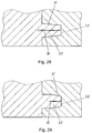
- Fig. 2 shows a mounting plate 6 in a groove receiving this 4.
- the side surfaces of the groove 4 have molded, elastic, wedge-shaped projections 11 (ribs) for centrally positioning and / or clamping fixing mounting plates 6 different width.
- a fire protection plate 8 or panel 8 'on On the space inside surface 7 of the Untersparrendämmplatte 1 is a fire protection plate 8 or panel 8 'on.
- the depth of the groove 4 is greater than the thickness of the slat 6. This embodiment is preferred for uneven / curved slats 6.
- Fig. 3 shows an embodiment of a groove 4 with a mounting batten 6, wherein the molded, elastic wedge-shaped projections 11 on the side surfaces of the groove 4 set straight, flat mounting slats 6 different width in the groove 4 centering and clamping.
- a fire protection plate 8 or panel 8 'on On the straight, flat mounting batten 6 is a fire protection plate 8 or panel 8 'on.
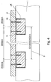
- Fig. 4 shows the central grid spacing 9 of the grooves 4.5 for receiving mounting battens 6 or square profile rails 6 'of 50 and / or 100 and / or 200 and / or 400 mm.
- a screw 10 standard fire protection panels 8 are fixed with a length of 2000 mm without shortening at their horizontal ends to the mounting slats 6.
- Fig. 5 shows a groove 4.5 with a lying in her mounting batten 6 and the elastic wedge-shaped or semicircular projections 11 on the side surfaces of the groove 4.5, which mounting plates 6 different width or square profile rails 6 'in the groove 4, 5 centered clamp.
- Fig. 5a shows another embodiment of the rib-shaped projections 11 on the side surfaces of the grooves 4, fifth
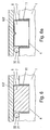
- Fig. 6 shows grooves 4.5 with straight, flat mounting slats 6 or square profile rails 6 'projecting beyond the space inside surface 7 of the Untersparzendämmplatte 1, which formed between the space inside surface 7 of the Untersparzendämmplatten 1 and the fire protection panels 8 or a panel 8', a free space 31 in which, for example, installations such as piping 32 can be accommodated.
- Fig. 6a shows this embodiment with a profile strip 6 'in place of a mounting batten.
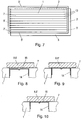
- Fig. 7 shows the surface 7 of a Untersparrendämmplatte 1 with horizontally extending groove 2 and spring 3, with vertically extending groove 2 'and spring 3', molded grooves in the form of pairs of slots 13 for receiving the legs of rails 14 with a central grid spacing of 50 and / or 100 and / or 200 and / or 400 mm. At all abutting edges surfaces 5 'extend for sealing by means of adhesive 15 or sealing tape 15'.
- Fig. 8 In the execution of Fig. 8 is the rail 14 against the space inside surface 7 of the Untersparzendämmplatte 1, which forms the support surface for fire protection panels 8 or a clothing 8 ', recessed, so that there is a recess between the webs of the profile strip 14 and the plate 8.
- Fig. 9 is the web of the rail 14 on the surface 7 of, so that the web of the rail 14, the support surface for fire protection panels 8 or a panel 8 'forms.
- Fig. 10 Aligns the web of the rail 14 with the space inside surface 7 of the Untersparzendämmplatte 1 so that these and the rail 14 form a support surface for fire protection panels 8 or a panel 8 '.
- Fig. 11, 11a and 11b show profile rails 14 in U-, L-, or T-shape with smooth web.
- Figs. 12, 12a and 12b show profile rails 14 with stiffening profiles 17 in the web and a V-profile 18 for receiving screw heads.
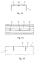
- Fig. 13 shows a rail 14 with a V-shaped profiling 18 for receiving screw heads.
- Fig. 14 shows a plan view of the rail 14 of Fig. 13 with prefabricated holes 19 for fasteners, such as mounting screws.
- Fig. 15 shows a Untersparrendämmplatte 1 in an embodiment for receiving profiled rails 14 with slots 13 in the space inside surface 7 and with a web of the rail 14 (not shown) corresponding profiled area 16 between the slots thirteenth
- Fig. 16 is an insulating Kunststoffbeilagsay 20 or rail 20 'provided in the V-shaped profiling 18 of a rail 14 for receiving screw heads.
- a sound-absorbing and / or intumescent coating 21 is provided on the interior surface of the profile rails 14.
- Fig. 18 shows how groove-shaped recesses horizontally 5 and vertically 5 "at the abutting edges of Untersparrendämmplatten 1 to a continuous, extending over all abutting edges level 5 'to grooves for the receptacles of mounting plates 6 or moldings 6' complement .
- an adhesive Also here are formed, elastic projections 11 on the side surfaces of the horizontal groove-shaped recesses 5 on the horizontal abutting edges of Untersparrendämmplatten 1 for centrally positioning and fixing of mounting slats 6 different width or square profile rails 6 'is provided.
- Fig. 20 shows in a sectional view parallel and transverse to the spring 3,3 'extending sealing lips 22 and resulting sealing chambers 23 on the side surfaces of the springs 3,3' in composite Untersparzendämmplatten first
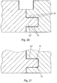
- a taper 24 is provided in the groove 2,2 'with the side surfaces approaching each other toward the bottom of the groove 2,2'.
- the taper 23 of the groove 2,2 'and the widening 25 of the spring 3,3' can also be present in combination ( Fig. 24 ).
- Fig. 25 shows a spring 3, 3 'which is elastically deformed by clamping in a sub-dimensioned groove 2, 2' in the slot area 26.
- Fig. 26 It is shown how a spring 3,3 'by the taper 24 of the groove 2,2' in its slot portion 26 is elastically deformed.
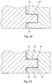
- Fig. 27 has the spring 3,3 'mutually inclined side surfaces 27 and a slot 26th
- Fig. 28 shows as by clamping the spring 3,3 'of Fig. 28 in the undersized, V-shaped groove 2,2 ', the spring 3,3' is elastically deformed in the slot area 26, the groove 2,2 'being tapered as a whole.
- Fig. 29 is an embodiment similar Fig. 28 shown, wherein the groove 2,2 'only in its groove bottom adjacent area (similar Fig. 22 ) is tapered.
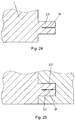
- Fig. 30 shows the arrangement of elastic sealing tapes 28 at the abutting edges of the sub-spar insulating panels 1 or at the bottom of the groove 2,2 'or at the end faces of the spring 3,3'.
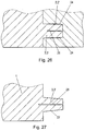
- Fig. 31 shows the bonding of the abutting edges of the Untersparrendämmplatten 1 and the adhesion to the bottom of the groove 2,2 'and the end face of the spring 3,3' by means of double-sided adhesive tapes 29 or adhesive 29 '.
- Fig. 32 In the side view of Fig. 32 is at the bottom of the horizontal groove 2 and on the horizontal end face of the vertical spring 3 'in parallel over portions extending from the bottom of the horizontal groove 2 in the horizontal surface of the vertical spring 3' and across the entire width of the horizontal groove 2 and across the entire horizontal width of the vertical spring 3 'extending, at least one molded sealing lip 30 or sealing wedge 30' is provided.
- Fig. 33 to Fig. 32 are at the bottom of the horizontal groove 2 and on the horizontal end face of the vertical spring 3 'in parallel over portions extending from the bottom of the horizontal groove 2 in the horizontal surface of the vertical spring 3' and across the entire width of the horizontal groove 2 and transverse over the entire horizontal width of the vertical spring 3 'extending, molded sealing lips 30 or sealing wedges 30' shown, wherein the spring 3 'may be formed with a slot 26.
- Fig. 34 is at the bottom of the vertical groove 2 'and on the vertical face of the horizontal spring 3 in parallel over portions extending from the bottom of the vertical groove 2' in the vertical surface of the horizontal spring 3 and across the entire width of the vertical groove 2 'and across the entire vertical width of the horizontal spring 3 extending, at least one molded sealing lip 30 or sealing wedge 30 'shown.
- Fig. 35 shows the top view Fig. 34 wherein the vertical end face of the horizontal spring 3 extends in parallel over portions extending from the bottom of the vertical groove 2 'into the vertical surface of the horizontal spring 3 and across the entire width of the vertical groove 2' and across the whole vertical width of the horizontal spring 3 extending, one or more of the spring 3 with slot 26 may be formed.
- Fig. 36 can be provided in the space inside surface 7 and / or stepped surface 5 'of a Untersparzendämmplatte 1 recesses 33,33' with deflection 34 'for receiving heating pipes / cooling tubes 34. Furthermore, parallel and / or transverse to the recesses 33,33 'arranged intoleitbleche /deleitbleche 35 or sautfolien / Kälteleitfolien 35', with horizontally extending groove 2 and spring 3, with vertically extending groove 2 'and spring 3', molded grooves 4, 5 for receiving mounting slats 6 or 4-edged profile rails 6 'with a central grid spacing of 50 and / or 100 and / or 200 and / or 400 mm and extending at all abutting edges surface 5' for sealing by means of adhesive tape 15 or sealing tape 15 'may be provided ,
- Fig. 37 shows on the space inside surface 7 of the Untersparzendämmplatte 1 a molded recess 33 with therein arranged heating pipe / cooling tube 34 and flat resting fire protection plate 8 or panel 8 '.
- Fig. 38 engages in the region of the space inside surface 7 of the Untersparzendämmplatte 1 befindliches heating pipe / cooling tube 34 partially in a molded-recess 33 'of the plate 1 and partially in applied plaster 36 a.
- Fig. 39 shows an embodiment of a Untersparrendämmplatte 1 having on its interior inside a Untersparzendämmplatte 1 with horizontally extending groove 2, and with a spring 3, with vertically extending groove 2 'and spring 3', molded grooves 4 for receiving mounting battens 6 or square profile rails 6 ' and with horizontally molded slots 13 for receiving rails 14 with a central grid spacing of 50 and / or 100 and / or 200 and / or 400 mm and extending at all abutting edges surface 5 'for sealing by means of adhesive tape 15 or sealing tape 15', the horizontal abutting edge groove 5 and the vertical abutting edge groove 5 ''.
- Fig. 40 shows how on the space inside 7 and / or space outside surface of the Untersparzendämmplatte 1 molded and numbered cutting marks 37 may be provided.
- In the space inside surfaces 7 of the insulation boards 1 grooves 4 are provided for receiving strips 6.
- On the strips 6 fire protection or cladding panels 8,8 'are attached.
- At the edges of the insulation boards 1 grooves 2 and springs 3 are provided, via which adjacent insulation boards 1 are positively connected with each other. The joints between adjacent insulating panels 1 are sealed.
- the insulation boards 1 have at the edges grooves 2,2 'and springs 3,3' for positive connection with other insulation boards 1, wherein at the edges of the insulation board 1 longitudinal recesses are provided in the region of the vertical abutting edges of adjacent insulation boards.
- 1 a vertical Stoßkantennut 5 "and in the region of the horizontal abutting edges of adjacent insulation boards 1 a horizontal Stoßkantennut 5 for receiving strips 6, 6 'form.
Description
Die Erfindung betrifft eine Dämmplatte für eine Dämmung, vorzugsweise rechteckige Dämmplatte, insbesondere Untersparrendämmplatte, wobei die Dämmplatte in einer ihrer Großflächen wenigstens eine Nut zur Aufnahme von Leisten und an ihren Rändern Nuten und Federn zum formschlüssigen Verbinden mit anderen Dämmplatten aufweist.The invention relates to an insulating board for insulation, preferably rectangular insulation board, in particular Untersparzendämmplatte, wherein the insulation board in one of its large areas has at least one groove for receiving strips and at their edges grooves and springs for positive connection with other insulation boards.
Die steigenden Ansprüche an die Wirksamkeit von Dämmungen, insbesondere Wärmedämmungen im Steildachbereich, haben dazu geführt, dass zweilagige Vollsparrendämmungen ausgeführt werden, da sonst die erforderlichen Dämmstärken als Zwischensparrendämmung nicht verwirklich werden können.The increasing demands on the effectiveness of insulation, especially thermal insulation in the pitched roof area, have led to the fact that two-ply Vollsparrendämmungen be performed, otherwise the required insulation thicknesses as Zwischenparspendentämmung can not be realized.
Die bekannten Vollsparrendämmungen werden so ausgeführt, dass zwischen den Sparren des Steildaches direkt unter der Dachschalung Dämmmaterial (Mineralwolle, Steinwolle oder Kunstschaumstoffdämmplatten) angebracht wird. Danach wird auf der Dachinnenseite der Dachsparren eine Konstruktionslattung (meistens aus Holzleisten) aufgebracht. Zwischen den Latten der Konstruktionslattung wird eine zweite Lage Dämmmaterial eingebracht. Schließlich wird auf der Konstruktionslattung eine Dampfbremse (Folie) angebracht, und die Lattung (zumeist aus Holz) zur Montage von Brandschutzplatten unter einer Verkleidung befestigt.The known Vollsparrendämmungen be designed so that between the rafters of the pitched roof directly under the roof formwork insulation (mineral wool, rock wool or plastic foam insulation boards) is attached. Thereafter, a construction battens (mostly made of wooden slats) is applied to the roof inside of the rafters. Between the slats of the construction battens a second layer of insulating material is introduced. Finally, a vapor barrier (foil) is attached to the construction battens, and the battens (mostly made of wood) are fastened under a covering to assemble fire protection boards.
Wegen der Holzkonstruktion entstehen an den Kreuzungspunkten Sparren/Konstruktionslatten unerwünschte Wärmebrücken, welche von der Dachaußenseite in den Dachinnenraum führen.Because of the wooden structure, unwanted thermal bridges, which lead from the outside of the roof into the roof interior, are created at the crossing points of rafters / construction slats.
Ein weiterer Nachteil der bekannten Dämmungen ist die Gefahr von Feuchtebildung im Dämmmaterial durch Kondensation von Wasserdampf, weil feuchte, warme Raumluft beim Ausströmen unter den Taupunkt abkühlt und Wasserdampf kondensiert. In Folge von möglichen Undichtigkeiten in der Dampfsperre oder Dampfbremse sammelt sich im Dämmmaterial Feuchte an.Another disadvantage of the known insulation is the risk of moisture formation in the insulating material by condensation of water vapor, because moist, warm room air cools when flowing below the dew point and condenses water vapor. As a result of possible leaks in the vapor barrier or vapor barrier, moisture accumulates in the insulation material.
Bekannt sind Vollsparrendämmungen, bei denen eine Untersparrendämmplatte verwendet wird, die an der Rauminnenseite mit Ausnehmungen zur Aufnahme von Montagelatten versehen ist. Diese Ausnehmungen sind parallel zur Firstlinie verlaufend ausgerichtet. Das Befestigen der Untersparrendämmplatten erfolgt bei der bekannten Dämmung mit Schrauben oder Nägeln, welche die Montagelatten und die Dämmplatten durchdringen und in die Dachsparren eingreifen (
Ein Nachteil dieser Untersparrendämmplatten ist, dass die Tiefe der Montagelatten aufnehmenden Nuten meist der Höhe der Montagelatten entspricht, sodass die Montagelatten mit der raumseitigen Oberfläche der der Dämmelemente fluchtend abschließen. Da in der Regel Holzlatten als Montagelatten verwendet werden und diese im Normalfall nicht gerade sind, ergibt sich der Nachteil, dass unebene Montagelatten über die rauminnenseitige Oberfläche der Dämmelemente in das Rauminnere vorstehen. Wenn die Montage der Brandschutzplatten auf unebenen Dachlatten durchgeführt wird, ist die gewünschte, gerade und ebene Fläche einer rauminnenseitigen Verkleidung nicht herstellbar. Ferner entspricht die Breite der die Montagelatten aufnehmenden Nuten dem Normmaß der Montagelatten (Holzdachlatten). Dies hat zwei gravierende Nachteile. Einerseits können Montagelatten (Holzdachlatten), die in ihrer Breite auch nur ein geringes Übermaß haben, in die vorgesehenen Nuten zur Aufnahme derselben nicht eingelegt werden. Wenn die Montagelatten (Holzdachlatten) anderseits ein Untermaß haben, ist eine mittige Ausrichtung in den Nuten zur korrekten Befestigung zweier Brandschutzplatten, mit gleicher Auflagefläche auf den Montagelatten an den Stoßkanten, nur sehr schwer möglich.A disadvantage of these Untersparrendämmplatten is that the depth of the mounting slats receiving grooves usually corresponds to the height of the mounting battens, so that the mounting battens with the room-side surface of the insulation elements in alignment. Since wooden slats are usually used as mounting slats and they are not straight in the normal case, there is the disadvantage that uneven mounting slats protrude beyond the space inside surface of the insulation elements in the interior of the room. If the installation of the fire protection panels is carried out on uneven roof battens, the desired, even and flat surface of a room interior panel can not be produced. Furthermore, the width of the grooves receiving the mounting slats corresponds to the standard dimension of the mounting slats (wooden roof slats). This has two serious disadvantages. On the one hand mounting slats (wooden roof slats), which have only a slight excess in their width, can not be inserted into the grooves provided for receiving the same. If the mounting battens (wooden roof battens) on the other hand have an undersize, a central alignment in the grooves for the correct attachment of two fire protection plates, with the same bearing surface on the mounting battens at the abutting edges, is very difficult.
Die, bevorzugt aus geschäumtem Polystyrol gefertigten, bekannten Untersparrendämmplatten sind an ihren Stoßkanten mit klemmenden, ein- oder zweifachen Nut- und Federausformungen versehen. Ein Nachteil dieser klemmend ausgeführten Nut- und Federausformungen ist, dass sich die Dämmplatten durch den hohen Reibungswiderstand des Dämmmaterials und der großen Klemmfläche der Nut- und Federausformung nur sehr schwer zusammenfügen lassen. Ein weiterer Nachteil dieser klemmenden, ein- oder zweifachen Nut- und Federausformung ist, dass in montiertem Zustand eine Luftdurchgängigkeit im Bereich der T- oder Kreuzstoßkanten der Nut- und Federausformung gegeben ist.The, preferably made of foamed polystyrene, known Untersparzendämmplatten are provided at their abutting edges with clamping, single or double tongue and groove formations. A disadvantage of this clamped running tongue and groove formations is that the insulation panels can be very difficult to assemble due to the high frictional resistance of the insulating material and the large clamping surface of the tongue and groove formation. Another disadvantage of this clamping, one or two-fold groove and Federausformung is that in the assembled state an air permeability in the area of T or Kreuzstoßkanten the tongue and groove shape is given.
Der Erfindung liegt die Aufgabe zu Grunde eine Dämmplatte sowie eine Dämmung der eingangs genannten Gattung anzugeben, welche eine einfache Montage erlaubt und eine zuverlässige Dämmung ergibt.The invention has for its object to provide an insulation board and an insulation of the type mentioned, which allows easy installation and provides a reliable insulation.
Gelöst wird diese Aufgabe erfindungsgemäß mit einer Dämmplatte, welche die Merkmale von Anspruch 1 aufweist.This object is achieved according to the invention with an insulating board, which has the features of
Bevorzugte und vorteilhafte Ausgestaltungen der Erfindung sind Gegenstand der Unteransprüche.Preferred and advantageous embodiments of the invention are Subject of the dependent claims.
Erfindungsgemäß ist vorgesehen, dass an den Rändern der Dämmplatte längslaufende Aussparungen vorgesehen sind, die im Bereich der vertikalen Stoßkanten von einander angrenzenden Dämmplatten eine vertikale Stoßkantennut und im Bereich der horizontalen Stoßkanten von einander angrenzenden Dämmplatten eine horizontale Stoßkantennut zur Aufnahme von Leisten bilden.According to the invention, longitudinal recesses are provided on the edges of the insulating board, which form a vertical abutting edge groove in the region of the vertical abutting edges of adjacent insulating boards and a horizontal abutting edge groove for receiving strips in the region of the horizontal abutting edges of adjacent insulating boards.
Mit der Erfindung wird eine Dämmung geschaffen, bei welcher Untersparrendämmplatten verwendet werden, die auch bei nicht geraden bzw. ebenen Montagelatten den Vorteil haben, dass die Latten nicht über die rauminnenseitige Fläche der Untersparrendämmplatte vorstehen.With the invention, an insulation is provided in which Untersparrendämmplatten be used, which have the advantage that the slats do not protrude beyond the space inside surface of the Untersparzendämmplatte even when not straight or flat mounting slats.
Des Weiteren kann die Lage und der Abstand von Montagelatten oder von Profilschienen an die unterschiedlichen Längen von Brandschutzplatten angepasst werden.Furthermore, the position and spacing of mounting battens or rails can be adapted to the different lengths of fire protection boards.
In einer beispielhaften Ausführungsform stellt die Erfindung eine Wärmedämmung zur Verfügung, welche eine wärmebrückenfreie Untersparrendämmplatte für den Steildach- und Deckenbereich benützt, bei der durch eine bevorzugte Ausbildung im Nut- und Federbereich durch Klemmen oder Kleben im Bereich der Stoßkanten zwischen aneinandergrenzenden Dämmplatten eine wind- und wasserdampfkonvektionsdichte Schicht gegeben ist. Bei Verwendung von Holzlatten als Montagelatten, bildet die rauminnenseitige Fläche der Untersparrendämmplatte oder bilden die Montagelatten die Auflagefläche für Brandschutzplatten oder eine andere Verkleidung (rauminnenseitig), wobei das Montieren von Brandschutzplatten einfach ist.In an exemplary embodiment, the invention provides a thermal insulation, which uses a heat bridge-free Untersparzendämmplatte for the pitched roof and ceiling area, in which by a preferred training in tongue and groove area by clamping or gluing in the region of the abutting edges between adjacent insulation boards a wind and steam convection-dense layer is given. When using wooden slats as mounting slats, forms the space inside surface of Untersparrendämmplatte or form the mounting slats the support surface for fire protection panels or other cladding (interior space side), the mounting of fire protection boards is easy.
Erfindungsgemäß ist in einer bevorzugten Ausführungsform vorgesehen, dass die Tiefe der die Montagelatten aufnehmenden Nut die Höhe der Montagelatten übersteigt, sodass auch bei der Verwendung gebogener Montagelatten nur die ebene, rauminnenseitige Oberfläche der Untersparrendämmplatte die Auflagefläche für Brandschutzplatten oder eine andere Verkleidung bildet, da die Tiefe der Nut das Maß der Montagelatten zuzüglich das Maß deren Durchbiegung übersteigt.According to the invention, it is provided in a preferred embodiment that the depth of the mounting slats receiving groove exceeds the height of the mounting slats, so that even when using curved mounting slats only the flat, interior space surface of the Untersparrendämmplatte forms the support surface for fire protection panels or other panel, since the depth the groove exceeds the dimension of the mounting slats plus the extent of their deflection.
Bei Verwendung von ebenen und geraden Montagelatten kann die Nut auch derart ausgeführt sein, dass die Tiefe der Nut die Höhe der Montagelatten unterschreitet, sodass nur die Montagelatten die Auflagefläche für Brandschutzplatten oder eine andere Verkleidung bilden. Der so zwischen den (Untersparren-)Dämmplatten und Brandschutzplatten vorliegende Freiraum ist im Brandfall vorteilhaft weil Wärme von den Brandplatten nicht direkt auf die Dämmplatten übertragen werden kann.When using flat and straight mounting slats, the groove can also be designed so that the depth of the groove is less than the height of the mounting slats, so that only the mounting slats form the support surface for fire protection panels or other cladding. The space between the (sub-rafter) insulation boards and fire protection boards is advantageous in case of fire because heat from the fire boards can not be transferred directly to the insulation boards.
Die rauminnenseitige Fläche der Untersparrendämmplatten kann mit einer Vielzahl von Ausnehmungen im mittigen Rasterabstand von 50 und/oder 100 und/oder 200 und/oder 400 mm zur Aufnahme von Montagelatten, vierkantigen Profilschienen oder anderen Profilschiene versehen sein. So sind die Montagelatten, vierkantigen Profilschienen oder Profilschienen am horizontalen Ende von Brandschutzplatten mit einer Länge von 2000 mm zu deren Montage positionierbar. Alternativ kann der Abstand der Ausnehmungen zur Aufnahme der Montagelatten, vierkantigen Profilschienen oder Profilschienen durch ihren mittigen Rasterabstand den Abmessungen von Brandschutzplatten entsprechen, sodass diese an ihren horizontalen Enden ohne Kürzen und Bearbeiten an den Montagelatten, vierkantigen Profilschienen oder Profilschienen verschraubbar sind. Dieses Rastermaß (z. B. 200mm) erlaubt es, die für das Befestigen von Brandschutzplatten vorgesehene Lage der Befestigungspunkte (wenigstens 100mm innerhalb des Randes der Brandschutzplatte) ohne weiteres einzuhalten.The space inside surface of Untersparrendämmplatten can be provided with a plurality of recesses in the central grid spacing of 50 and / or 100 and / or 200 and / or 400 mm for receiving mounting battens, four-sided rails or other rail. Thus, the mounting slats, square profile rails or rails can be positioned at the horizontal end of fire protection boards with a length of 2000 mm for their installation. Alternatively, the distance between the recesses for receiving the mounting slats, square rails or rails by their central grid spacing correspond to the dimensions of fire protection boards, so that they can be screwed at their horizontal ends without shortening and editing the mounting slats, four-sided rails or rails. This pitch (eg 200mm) allows to easily maintain the location of the attachment points (at least 100mm within the edge of the fire protection panel) for fixing fire protection panels.
Vorteilhaft ist es, wenn die Ausnehmungen zur Aufnahme von Montagelatten derart gestaltet sind, dass auch Montagelatten welche die Normbreite von Montagelatten (Holzdachlatten) unter- oder überschreiten mittig in der Nut zur Aufnahme von Montagelatten positionierbar sind und festhaftend bis zur endgültigen Montageverschraubung in ihrer Einbaulage verbleiben, so dass eine "Einmannmontage" möglich ist.It is advantageous if the recesses for receiving mounting slats are designed so that even mounting slats which under the standard width of mounting slats (wooden slats) or exceed centered in the groove for receiving mounting slats are positioned and remain adherent to the final mounting screw in its installed position , so that a "one-man assembly" is possible.
Bezugnahmen auf "horizontal", "vertikal" usw. in dieser Beschreibung beziehen sich jeweils auf die Gebrauchslage von Dämmplatten.References to "horizontal", "vertical", etc. in this specification refer to the position of use of insulation boards, respectively.
Erfindungsgemäß ist in einer anderen Ausführungsform der Erfindung beispielsweise vorgesehen, dass die Breite der Nut zur Aufnahme von Montagelatten größer ist als das Normmaß der Breite von Montagelatten (Holzdachlatten). An beiden Seitenflächen der Nut sind in einer bevorzugten Ausführungsform keilförmige, elastische Anformungen angeformt sein. Der Abstand zwischen den an den zur Ebene der Dämmplatten senkrecht stehenden Seitenflächen der Nut gegenüberliegenden, keilförmigen Anformungen voneinander ist bevorzugt kleiner als das Normmaß der Breite von Montagelatten (Holzdachlatten), wodurch beim Einschieben der Montagelatten in die Nuten ein mittiges Positionieren und klemmendes Fixieren der Montagelatten in der Nut durch die elastischen, keilförmigen Anformungen an den Seitenflächen der Nut erfolgt. Diese zur mittigen Positionieren und Klemmen der Montagelatten dienenden keilförmigen Anformungen können beliebig, horizontal oder vertikal, durchgehend oder sich nur über Teilbereiche erstreckend, gegenüberliegend oder versetzt, an den (einander zugewendeten) Seitenflächen der Nut zur Aufnahme von Montagelatten angeformt sein. Die zum mittigen Positionieren und/oder klemmenden Fixieren der Montagelatten dienenden, keilförmigen, elastischen Anformungen können auch halbrund oder in einer beliebig anderen Form ausgeführt sein. Die zuvor beschriebenen elastischen Anformungen können wahlweise auch nur an einer Seitenfläche von Nuten angeformt sein.According to the invention, in another embodiment of the invention, for example, provided that the width of the groove for receiving mounting battens is greater than the standard dimension of the width of mounting battens (wooden roof battens). On both side surfaces of the groove are in one preferred embodiment wedge-shaped, elastic projections be formed. The distance between the at the plane of the insulation boards perpendicular side surfaces of the groove opposite, wedge-shaped projections from each other is preferably smaller than the standard size of the width of mounting battens (wooden roof slats), whereby when inserting the mounting slats in the grooves a central positioning and clamping fixing the mounting slats takes place in the groove by the elastic, wedge-shaped projections on the side surfaces of the groove. These wedge-shaped projections serving for the central positioning and clamping of the mounting slats can be formed integrally, horizontally or vertically, continuously or only over partial areas, opposite or offset, on the (mutually facing) side surfaces of the groove for receiving mounting slats. The wedge-shaped, elastic projections which serve for the central positioning and / or clamping fixing of the mounting slats can also be designed semicircular or in any other desired form. The elastic projections described above may optionally also be formed only on a side surface of grooves.
Bei der Verwendung ebener und gerader Montagelatten oder vierkantigen Profilschienen kann die Tiefe der Nut an der rauminnenseitigen Fläche der Untersparrendämmplatten beliebig sein, sodass die Montagelatten oder vierkantigen Profilschienen über die rauminnenseitige Fläche der Untersparrendämmplatten hinaus in die Rauminnenseite ragen, um zwischen der rauminnenseitigen Fläche der Untersparrendämmplatten und den Brandschutzplatten oder Verkleidung einen Installationsraum für Verrohrungen zu schaffen.When using flat and straight mounting slats or square profile rails, the depth of the groove on the space inside surface of Untersparrendämmplatten may be arbitrary, so that the mounting slats or square profile rails beyond the space inside surface of the Untersparrendämmplatten out into the room interior to between the space inside surface of Untersparzendämmplatten and To provide the fire protection panels or cladding an installation space for piping.
Elastische Anformungen zum klemmenden Fixieren der Montagelatten oder vierkantigen Profilschienen an den Seitenflächen der Nut können auch, wie oben beschrieben, nur über Teilbereiche der Höhe der Montagelatten oder vierkantigen Profilschienen aufnehmenden Nut angeformt sein.Elastic projections for clamping fixing the mounting slats or four-sided rails on the side surfaces of the groove can also, as described above, be formed only over portions of the height of the mounting slats or four-sided rails receiving groove.
An der rauminnenseitigen Fläche der Untersparrendämmplatten können auch Markierungen im mittigen Rasterabstand von 50 und/oder 100 und/oder 200 und/oder 400 mm aufgebracht oder angeformt sein, um ein aufwändiges Einmessen der Abstände von horizontal zu montierenden Montagelatten, vierkantigen Profilschienen oder Montagebrettern zu vermeiden, sofern auf Nuten zur Aufnahme oder teilweisen Aufnahme von Montagelatten oder vierkantigen Profilschienen verzichtet werden kann.Markings in the central grid spacing of 50 and / or 100 and / or 200 and / or 400 mm can also be applied or integrally formed on the space inside surface of the sub-rafter insulation panels in order to avoid time-consuming measuring of the distances between mounting slats to be mounted horizontally, quadrangular profile rails or mounting boards , provided on grooves for receiving or partially receiving mounting slats or four-edged rails can be dispensed with.
Wenn die horizontal verlaufenden Markierungen an der rauminnenseitigen Fläche der Untersparrendämmplatten von den vertikalen Stoßkanten beabstandet sind und somit eine durchgehend glatte Oberfläche zum Abkleben mittels Klebe- oder Dichtband gebildet wird, kann auf Vertiefungen an den Stoßkanten der Untersparrendämmplatten verzichtet werden. Ferner wird eine Installationsebene für Verrohrungen gebildet.If the horizontally extending markings on the space inside surface of the Untersparrendämmplatten are spaced from the vertical abutting edges and thus a continuous smooth surface for masking by means of adhesive or sealing tape is formed, can be dispensed with depressions on the abutting edges of Untersparrendämmplatten. Furthermore, an installation level for piping is formed.
Zum Befestigen der Brandschutzplatten können auch in den Untersparrendämmplatten festgelegte, Profilschienen (aus Metall) verwendet werden.For fixing the fire protection boards also fixed in the Untersparzendämmplatten, rails (made of metal) can be used.
Bei der Verwendung von (Metall-)Profilschienen zum Befestigen von Brandschutzplatten ist erfindungsgemäß die rauminnenseitige Fläche der Untersparrendämmplatte in einer beispielhaften Ausführungsform derart ausgestaltet, dass die Nuten als horizontal verlaufende, schlitzartige Nuten (Ausnehmungen) in der rauminnenseitigen Fläche der Untersparrendämmplatten ausgebildet sind, in welche Schenkel von Profilschienen einschiebbar sind.When using (metal) rails for attaching fire protection boards according to the invention, the space inside surface of Untersparrendämmplatte in an exemplary embodiment configured such that the grooves are formed as horizontally extending, slot-like grooves (recesses) in the space inside surface of the Untersparzendämmplatten, in which Legs of rails are inserted.
Vorteilhaft ist es, die schlitzförmigen Nuten zur Aufnahme der Schenkel von Profilschienen schmäler als die Dicke der Schenkel von Profilschienen zu gestalten, sodass die Schenkel von Profilschienen klemmend in die schlitzförmigen Nuten einschiebbar sind und die Profilschienen in der Dachschräge und an der Decke festhaftend bis zur endgültigen Montageverschraubung in den Untersparrendämmplatten gehalten sind. Dadurch wird eine "Einmannmontage" der Profilschienen möglich gemacht.It is advantageous to make the slot-shaped grooves for receiving the legs of rails narrower than the thickness of the legs of rails, so that the legs of rails are clamped inserted into the slot-shaped grooves and the rails in the roof pitch and the ceiling adherent to the final Fitting are held in the Untersparrendämmplatten. As a result, a "one-man assembly" of the rails is made possible.
Die Schenkel der Profilschienen und gegengleiche Ausnehmungen an der rauminnenseitigen Fläche der Untersparrendämmplatte können auch derart ausgestaltet sein, dass die Profilschienen selbsthaftend bis zur endgültigen Montageverschraubung in den Untersparrendämmplatten verbleiben.The legs of the rails and gegengleiche recesses on the space inside surface of Untersparrendämmplatte can also be designed such that the rails remain self-adhesive to the final assembly in the Untersparrendämmplatten.
Durch die in einer Ausführungsform der Erfindung als horizontale Schlitze ausgebildeten Nuten, die in einem mittigen Rasterabstand von 50 und/oder 100 und/oder 200 und/oder 400 mm angeordnet sind, und zur Aufnahme von Profilschienen an der rauminnenseitigen Fläche der Untersparrendämmplatten dienen, ist ein exaktes Anpassen und Positionieren der Profilschienen zum Befestigen der horizontalen Stoßkanten von Brandschutzplatten oder Verkleidungen ohne Kürzen derselben an der Rauminnenseite der Untersparrendämmplatten gewährleistet.By formed in one embodiment of the invention as horizontal slots grooves which are arranged in a central grid spacing of 50 and / or 100 and / or 200 and / or 400 mm, and to Receiving rails on the space inside surface of Untersparrendämmplatten serve, an exact fitting and positioning of the rails for securing the horizontal abutting edges of fire protection panels or panels is guaranteed without shortening the same on the inside of the Untersparrendämmplatten.
An der rauminnenseitigen Fläche der Untersparrendämmplatten können gegengleiche Ausnehmungen für die Profilschienen wahlweise derart angeordnet sein, dass die Profilschienen plan mit der rauminnenseitigen Fläche der Untersparrendämmplatten abschließen, sodass die Profilschienen und die rauminnenseitigen Fläche der Untersparrendämmplatten die Auflagefläche für Brandschutzplatten oder Verkleidungen bilden. Alternativ sind die gegengleichen Ausnehmungen zur Aufnahme der Profilschienen vertieft, sodass die Auflagefläche der Brandschutzplatten oder Verkleiden die rauminnenseitige Fläche der Untersparrendämmplatten ist. Es ist auch in Betracht gezogen, dass keine gegengleichen Ausnehmung für die rauminnenseitige Fläche der Profilschienen an der rauminnenseitigen Fläche der Untersparrendämmplatten eingeformt ist, sodass die Profilschienen (alleine) die Auflagefläche für Brandschutzplatten oder Verkleidungen bilden.On the space inside surface of the Untersparrendämmplatten gegengleiche recesses for the rails can be optionally arranged such that the rails flush with the space inside surface of the Untersparrendämmplatten so that the rails and the space inside surface of the Untersparzendämmplatten form the support surface for fire protection panels or panels. Alternatively, the opposite recesses for receiving the rails are recessed, so that the bearing surface of the fire protection panels or disguising is the space inside surface of the Untersparzendämmplatten. It is also contemplated that no opposite recess for the space inside surface of the rails is formed on the space inside surface of Untersparrendämmplatten so that the rails (alone) form the support surface for fire protection panels or panels.
Die Profilschienen zum Befestigen der Untersparrendämmplatten an Dachsparren oder Deckenzangen einerseits und von Brandschutzplatten oder Bekleidungen anderseits können als U-Profil-Leisten, L-Profil-Leisten, T-Profil-Leisten, glatt mit beliebigem Versteifungsprofilen oder glatt ohne Profil in ihren Stegen ausgeführt sein.The rails for attaching the Untersparrendämmplatten to rafters or ceiling pliers on the one hand and fire protection boards or clothing on the other hand can be designed as U-profile strips, L-profile strips, T-profile strips, smooth with any stiffening profiles or smooth without profile in their webs ,
Die Profilschienen zum Befestigen von Brandschutzplatten oder einer Verkleidung an der Rauminnenseite der Untersparrendämmplatten können aus Metall, Kunststoff oder aus einem beliebigen anderen, für diesen Anwendungszweck geeigneten Material hergestellt sein.The profile rails for attaching fire protection panels or a cladding on the interior side of the Untersparrendämmplatten may be made of metal, plastic or any other suitable material for this application.
Vorteilhaft ist es, in die Profilschienen vorgefertigt eine durchlaufende, oder nur im Bereich von Löchern für Befestigungsmittel eine gegengleiche Profilierung entsprechend der Größe und Form eines Kopfes (z. B. Schraubenkopfes) sowie vorgefertigte Lochungen für die Verschraubung vorzusehen, wodurch eine plane Auflage der Brandschutzplatten oder Verkleidung auf den Profilschienen gewährleistet ist und die Profilschienen bei der Verschraubung an Dachsparren oder Deckenzangen nicht vorgebohrt werden müssen.It is advantageous to prefabricate into the profiled rails a continuous, or only in the area of holes for fastening means an opposite profiling according to the size and shape of a head (eg., Screw head) and provide prefabricated holes for the screw, whereby a flat support of the Fire protection panels or cladding is guaranteed on the rails and the rails must not be pre-drilled when screwing to rafters or ceiling pliers.
Diese durchlaufende oder partiell im Bereich der Löcher vorgefertigte Schraubkopfprofilierung sowie Versteifungsprofilierung in den Profilschienen sind wahlweise gegengleich in die rauminnenseitigen Fläche von Untersparrendämmplatten eingeformt.This continuous or partially prefabricated in the area of the holes Schraubkopfprofilierung and stiffening profiling in the rails are optionally formed gegengleich equal to the space inside surface of Untersparzendämmplatten.
Zur Vermeidung von Wärmebrücken durch Montageschrauben zu den Profilschienen, sofern diese aus Metall gefertigt werden, können an den vorgefertigten Löchern zur Montageverschraubung isolierende Kunststoffbeilagscheiben angebracht sein. Diese Funktion kann auch von einer durchgehenden, profilierten und gelochten Kunststoffschiene übernommen werden.To avoid thermal bridges by mounting screws to the rails, if they are made of metal, insulating plastic shims may be attached to the prefabricated holes for mounting screw. This function can also be taken over by a continuous, profiled and perforated plastic rail.
Sofern die Profilschiene derart ausgeführt ist, dass diese die Auflagefläche für die Brandschutzplatten oder Bekleidung bildet, kann zur schalltechnischen Optimierung eine Beschichtung auf der rauminnenseitigen oder plattenseitigen Fläche der Profilschienen aufgebracht sein.If the rail is designed such that it forms the bearing surface for the fire protection boards or clothing, a coating on the interior surface or plate-side surface of the rails can be applied to sound optimization.
Ferner kann die Profilschiene an ihrer rauminnenseitigen Fläche mit einer brandhemmenden (z.B. aufschäumenden) Beschichtung versehen werden.Furthermore, the profile rail can be provided with a fire-retardant (for example, foaming-up) coating on its interior surface.
Die rauminnenseitige Fläche der Untersparrendämmplatten kann auch derart ausgestaltet sein, dass horizontal verlaufende Nuten zur Aufnahme von Montagelatten und horizontal verlaufende Schlitze (schlitzartige Nuten) zur Aufnahme der Schenkel von Profilschienen im mittigen Rasterabstand von 50 und/oder 100 und/oder 200 und/oder 400mm eingeformt sind.The space inside surface of Untersparrendämmplatten can also be designed such that horizontally extending grooves for receiving mounting slats and horizontally extending slots (slot-like grooves) for receiving the legs of rails in the central grid spacing of 50 and / or 100 and / or 200 and / or 400mm are formed.
Das Eindichten der Dämmfläche kann durch Abkleben der Stoßkanten von aneinander liegenden Untersparrendämmplatten mittels Klebe- oder Dichtband hergestellt werden.The sealing of the insulating surface can be made by masking the abutting edges of adjacent Untersparzendämmplatten by means of adhesive or sealing tape.
Sehr vorteilhaft ist es, wenn die Abklebung und/oder Abdichtung der horizontalen und vertikalen Stoßkanten aneinander anliegender Untersparrendämmplatten auf einer durchgehenden, planen Klebeebene bzw. Dichtungsebene ausgeführt wird.It is very advantageous if the masking and / or sealing of the horizontal and vertical abutting edges adjoin one another Untersparrendämmplatten is carried out on a continuous, plane adhesive plane or sealing level.
Da in der Untersparrendämmplatte - in der Gebrauchslage - horizontal verlaufende Nuten zur Aufnahme von Montagelatten, vierkantigen Profilschienen und/oder in Gebrauchslage horizontal verlaufende Schlitze zur Aufnahme von Profilschienen vorgesehen sind, gestaltet sich das Abkleben und/oder Eindichten der vertikalen Stoßkanten von aneinander anliegenden Untersparrendämmplatten manchmal schwierig. Bei der Ausführungsform mit Nuten zur Aufnahme von Montagelatten oder (vierkantigen) Profilschienen besteht die Gefahr, dass das in der Gebrauchslage vertikal verlaufendes Klebe- oder Dichtbandband an den Plattenstößen in den Ecken am Grund der Nut nicht völlig bündig in den Kanten verklebt wird. Undichtigkeiten der Dämmfläche, Wasserdampfkonvektion und eine damit verbundene Feuchtebildung durch ausströmende, feuchte Raumluft und Kondensation von Wasserdampf im Taupunktbereich wären die Folge. Bei der Ausführung mit horizontal verlaufenden Schlitzen zur Aufnahme von Profilschienen ist eine Eindichtung der vertikalen Stoßkanten von aneinander liegenden Untersparrendämmplatten mittels Klebe- oder Dichtband nicht ohne Aufwand herstellbar.Since in the Untersparrendämmplatte - in the use position - horizontally extending grooves for receiving mounting slats, four-sided rails and / or horizontally extending slots in the position of use are provided for receiving rails, the masking and / or sealing the vertical abutting edges of adjacent Untersparzendämmplatten sometimes designed difficult. In the embodiment with grooves for receiving mounting slats or (square) rails there is a risk that the vertically extending in the use position adhesive or sealing tape on the panel joints in the corners at the bottom of the groove is not completely flush bonded in the edges. Leakage of the insulating surface, water vapor convection and the associated formation of moisture by outflowing, humid room air and condensation of water vapor in the dew point range would be the result. In the version with horizontally extending slots for receiving rails a sealing of the vertical abutting edges of adjacent Untersparzendämmplatten means of adhesive or sealing tape can not be produced without effort.
In diesem Zusammenhang kann erfindungsgemäß in einer Ausführungsform vorgesehen sein, dass an beiden vertikalen und beiden horizontalen Stoßkanten der Untersparrendämmplatten Vertiefungen vorgesehen sind, die zumindest der Höhe der Nut zur Aufnahme von Montagelatten, vierkantigen Profilschienen oder der Höhe von Schlitzen zur Aufnahme der Schenkel von Profilschienen sowie der halben Breite der vorzusehenden Klebe- oder Dichtbändern entspricht, wodurch horizontal und vertikal eine durchgehende, plane Ebene zum Abkleben der Stoßkanten von aneinander liegenden Untersparrendämmplatten mittels Klebe- oder Dichtband gebildet wird.In this context, according to the invention can be provided in one embodiment that recesses are provided on both vertical and two horizontal abutting edges of Untersparrendämmplatten, at least the height of the groove for receiving mounting slats, four-sided rails or the height of slots for receiving the legs of rails and half the width of the adhesive or sealing tapes to be provided corresponds, whereby horizontally and vertically a continuous, planar plane for masking the abutting edges of adjacent Untersparzendämmplatten is formed by means of adhesive or sealing tape.
Im horizontalen Stoßkantenbereich kann diese nutförmige Ausnehmung zum Abkleben der Stoßkanten von aneinander liegenden Untersparrendämmplatten derart dimensioniert sein, dass diese Stoßkantennut in ihrer gesamten Breite und ihrer Höhe einer Nut zur Aufnahme von Montagelatten wie zuvor beschrieben oder vierkantigen Profilschienen entspricht und zu deren Aufnahme dient. An den Seitenflächen dieser horizontalen Stoßkantennut können, elastische Anformungen zum mittigen Positionieren und klemmenden Fixieren von Montagelatten oder vierkantigen Profilschienen wie zuvor beschrieben angeformt sein. Die elastischen Anformungen können wahlweise auch nur an einer Seitenfläche der Stoßkantennut angeformt sein.In the horizontal abutting edge region, this groove-shaped recess for masking the abutting edges of adjoining Untersparzendämmplatten be dimensioned such that this Stoßkantennut corresponds in its entire width and height of a groove for receiving mounting slats as described above or square rails and serves to accommodate them. To the Side surfaces of this horizontal Stoßkantennut, elastic moldings for central positioning and clamping fixing of mounting slats or four-sided rails can be formed as previously described. The elastic projections can optionally also be formed only on one side surface of the abutting edge groove.
Das Eindichten im Bereich der Nut-Feder-Ausformung im horizontalen und vertikalen Stoßkantenbereich von Untersparrendämmplatten wird erfindungsgemäß in einer beispielhaften Ausführungsform dadurch erreicht, dass die Feder schmäler ausgeführt ist, als das Innenmaß der Seitenflächen der Nut. Bevorzugt ist es, wenn auf der Feder an den aufragenden Flächen beidseitig parallel und quer zur Feder verlaufende Dichtlippen angeformt sind. Die Feder mit den an den Flächen beidseitig angeformten Dichtlippen ist größer als das Innenmaß der Seitenflächen der Nut dimensioniert, sodass die Feder mit den darauf angeformten Dichtlippen klemmend in die Nut einschiebbar ist. Bedingt durch die geringere Oberfläche der Dichtlippen und die dadurch reduzierte Reibung gegenüber einer herkömmlichen, vollflächig klemmenden, ein oder zweifachen Nut- und Federausformung, sind die Untersparrendämmplatten bei dieser Ausführungsform die Erfindung im Stoßkantenbereich bei der Montage mit wesentlich geringem Widerstand ineinander einschiebbar.The sealing in the region of the tongue and groove formation in the horizontal and vertical abutting edge region of Untersparrendämmplatten is inventively achieved in an exemplary embodiment in that the spring is made narrower than the inner dimension of the side surfaces of the groove. It is preferred if on the spring on the rising surfaces on both sides parallel and transverse to the spring extending sealing lips are formed. The spring with the sealing lips formed on both sides on the surfaces is dimensioned larger than the internal dimension of the side surfaces of the groove, so that the spring with the sealing lips formed thereon can be inserted into the groove by clamping. Due to the lower surface of the sealing lips and the resulting reduced friction compared to a conventional, full-surface clamping, one or two-fold tongue and groove formation, the Untersparzendämmplatten in this embodiment, the invention in the abutting edge region during assembly with substantially low resistance inserted into one another.
Die parallel und quer an den Seitenflächen der Feder verlaufenden Dichtlippen haben den Vorteil, eine Vielzahl von Dichtkammern zu bilden. Sollten Dichtlippen vor dem Zusammenschieben angrenzender Untersparrendämmplatten bereichsweise beschädigt sein und somit die Dichtfunktion an einer Dichtkammer nicht mehr gegeben sein, bleibt die Dichtfunktion angrenzender Dichtkammern erhalten und damit die insgesamte Dichtigkeit im Stoßkantenbereich der Untersparrendämmplatten sichergestellt.The parallel and transverse to the side surfaces of the spring extending sealing lips have the advantage of forming a plurality of sealing chambers. If sealing lips are partially damaged prior to collapsing adjacent Untersparrendämmplatten and thus the sealing function on a sealing chamber no longer be given, the sealing function of adjacent sealing chambers is maintained and thus the overall tightness in the abutting edge region of Untersparrendämmplatten ensured.
Das Eindichten im Bereich der Nut- Federausformung im horizontalen und vertikalen Stoßkantenbereich von Untersparrendämmplatten kann erfindungsgemäß beispielsweise auch dadurch erreicht werden, dass die Breite der Feder kleiner ist, als die Breite des Innenmaßes der Nut. An den Seitenflächen der Nut ist zum Grund der Nut hin eine Verjüngung der Nut eingeformt, die schmäler ist als die Breite der Feder. In diese Verjüngung der Nut wird die Feder beim Einschieben in die Nut klemmend eingeschoben. Diese Verjüngung kann auf einer oder auf beiden Seitenflächen der Nut vorgesehen sein.The sealing in the region of the tongue and groove formation in the horizontal and vertical abutting edge region of Untersparrendämmplatten can according to the invention, for example, be achieved in that the width of the spring is smaller than the width of the inner dimension of the groove. At the side surfaces of the groove to the bottom of the groove, a taper of the groove is formed, which is narrower than the width of the spring. In this taper of the groove, the spring is inserted by clamping when inserted into the groove. This rejuvenation can be on one or both Side surfaces of the groove may be provided.
Diese Form des Eindichtens kann erfindungsgemäß beispielsweise auch derart ausgeführt sein, dass an die Feder zu ihrer Wurzel hin eine das Innenmaß der Nut übersteigende Verbreiterung aufweist, sodass die Nut auf die Feder klemmend aufschiebbar ist. Diese Verbreiterung im Bereich der Wurzel der Feder kann auf einer oder auf beiden Seitenflächen der Feder angeformt sein.According to the invention, this form of sealing can also be embodied, for example, such that the widening of the tongue towards its root has a widening that exceeds the inner dimension of the groove, so that the groove can be slid onto the spring in a clamping manner. This broadening in the region of the root of the spring can be formed on one or both sides of the spring.
Diese Eindichtungsvariante kann auch in Kombination ausgeführt werden, sodass eine Verjüngung der Nut zu ihrem Grund hin und eine Verbreiterung der Feder zu ihrer Wurzel hin angeformt sind.This sealing variant can also be made in combination, so that a taper of the groove to its base and a broadening of the spring are formed to its root.
Ein Eindichten der Untersparrendämmplatten im Stoßkantenbereich kann erfindungsgemäß auch dadurch hergestellt werden, dass in die Feder ein oder mehrere im wesentlichen parallel zu deren aufragenden Seitenflächen verlaufende/r Schlitz/e eingeformt ist/sind, welche/r sich über einen beliebigen Bereich der Höhe der Feder oder bis in den Bereich des Untersparrendämmkörpers hinein erstreckt. Die Feder ist breiter als die Nut. Beim Einschieben der Feder in die Nut werden die durch den/die Schlitz/e voneinander getrennten Teile der Feder elastisch an die seitlichen Flächen der Nut angepresst, wodurch ein elastisches, zuverlässiges Eindichten der Nut- und Federverbindung herstellbar ist. Dieses elastische Zusammendrücken der geschlitzten Feder kann auch durch Verjüngungen an den aufragenden Seitenflächen am Grund der Nut herbeigeführt und/oder verstärkt werden.A sealing of the Untersparrendämmplatten in the abutting edge region can also be prepared according to the invention by the fact that in the spring one or more substantially parallel to their upstanding side surfaces extending / e / s slot / e is / are formed, which / r over any range of the height of the spring or extends into the region of the Untersparrendämmkörpers inside. The spring is wider than the groove. Upon insertion of the spring into the groove, the parts separated by the slit (s) of the spring are resiliently pressed against the lateral surfaces of the groove, whereby an elastic, reliable sealing of the tongue and groove joint can be produced. This elastic compression of the slotted spring can also be brought about and / or reinforced by tapering on the upstanding side surfaces at the bottom of the groove.
Vorteilhaft ist es, wenn die Nut- und Federverbindung mit geschlitzter Feder im wesentlichen V-förmig gestalten ist. Durch diese V-förmige Ausformung kann die Feder über einen großen Bereich ohne Reibungswiderstand in die Nut eingeführt werden. Erst im letzen Abschnitt des Einschiebens der Feder in die Nut wird die Klemmung der elastischen, durch den/die Schlitz/e getrennten Teile der Feder wirksam, wodurch die Seitenflächen der Feder gegen die Seitenflächen der Nut gepresst werden, welche zu ihrem Grund hin um die Breite oder Teilbereiche der Breite des Schlitzes in der Feder schmäler ist.It is advantageous if the tongue and groove connection with slotted spring is substantially V-shaped. By this V-shaped configuration, the spring can be inserted over a large area without frictional resistance in the groove. Only in the last portion of the insertion of the spring into the groove, the clamping of the elastic, separated by the / slit / e parts of the spring is effective, whereby the side surfaces of the spring are pressed against the side surfaces of the groove, which towards its bottom to the Width or portions of the width of the slot in the spring is narrower.
Diese Form des Eindichtens kann auch als kombinierte, parallel und V-förmige, gegengleiche Nut- und geschlitzte Federverbindung ausgeführt sein.This form of sealing can also be designed as a combined, parallel and V-shaped, opposite groove and slotted spring connection be.
Das Eindichten im Stoßkantenbereich von aneinander anliegenden Untersparrendämmplatten kann erfindungsgemäß auch mit Hilfe elastischer Dichtbänder hergestellt werden. Die elastischen Dichtbänder können an den in der Gebrauchslage horizontalen und vertikalen Stoßkanten der Untersparrendämmplatten befestigt sein. Die elastischen Dichtbänder können aber auch am horizontalen und vertikalen Grund der Nut oder an den horizontalen und vertikalen Stirnflächen der Feder aufgebracht sein.The sealing in the abutting edge region of adjoining Untersparrendämmplatten can be made according to the invention also using elastic sealing strips. The elastic sealing bands may be attached to the horizontal and vertical abutting edges of the Untersparrendämmplatten in the position of use. But the elastic sealing bands can also be applied to the horizontal and vertical base of the groove or on the horizontal and vertical faces of the spring.
Das Eindichten im Stoßkantenbereich von aneinander anliegenden Untersparrendämmplatten kann erfindungsgemäß auch mittels Verkleben ausgeführt werden. Das Verkleben kann an den horizontalen und vertikalen Stoßkanten der Untersparrendämmplatten durchgeführt werden. Das Verkleben kann aber auch am horizontalen und vertikalen Grund der Nut und an den anliegenden horizontalen und vertikalen Stirnflächen der Feder erfolgen. Das Verkleben kann durch Kleberauftrag oder mittels eines beidseitig klebenden Klebebandes ausgeführt werden.The sealing in the abutting edge region of adjoining Untersparrendämmplatten can also be carried out according to the invention by means of gluing. The bonding can be performed on the horizontal and vertical abutting edges of the sub-rafter insulation panels. But the bonding can also be done on the horizontal and vertical base of the groove and on the adjacent horizontal and vertical faces of the spring. The bonding can be carried out by adhesive application or by means of a double-sided adhesive tape.
Erfindungsgemäß wird das Eindichten in T- oder Kreuzstoßkantenbereich der Nut- und Federausformung beispielsweise dadurch gelöst, dass am Grund der horizontalen Nut und an der horizontalen Stirnfläche der vertikalen Feder parallel über Teilbereiche sich vom Grund der horizontalen Nut in die horizontale Oberfläche der vertikalen Feder erstreckende und quer über die ganze Breite der horizontalen Nut und quer über die ganze horizontale Breite der vertikalen Feder sowie am Grund der vertikalen Nut und an der vertikalen Stirnfläche der horizontalen Feder parallel über Teilbereiche sich vom Grund der vertikalen Nut in die vertikalen Oberfläche der horizontalen Feder erstreckende und quer über die ganze Breite der vertikalen Nut und quer über die ganze vertikale Breite der horizontalen Feder verlaufende, eine oder mehrere Dichtlippen oder Dichtkeile angeformt sind. Beim Einschieben der angrenzenden Untersparrendämmplatten werden die Stirnflächen der horizontalen und vertikalen Feder gegen die Dichtlippen oder Dichtkeile gepresst. Das Verpressen der Dichtlippen oder Dichtkeile bewirkt das Eindichten im T- oder Kreuzstoßkantenbereich der Nut- und Federausformung, auch mit geschlitzter Feder.According to the invention, the sealing in T- or Kreuzstoßkantenbereich the tongue and groove molding is achieved, for example, that at the bottom of the horizontal groove and on the horizontal end face of the vertical spring in parallel over portions extending from the bottom of the horizontal groove in the horizontal surface of the vertical spring and across the entire width of the horizontal groove and across the entire horizontal width of the vertical spring and at the bottom of the vertical groove and on the vertical face of the horizontal spring parallel over portions extending from the bottom of the vertical groove into the vertical surface of the horizontal spring and transverse to the entire width of the vertical groove and across the entire vertical width of the horizontal spring extending, one or more sealing lips or sealing wedges are formed. When inserting the adjacent Untersparrendämmplatten the end faces of the horizontal and vertical spring are pressed against the sealing lips or sealing wedges. The compression of the sealing lips or sealing wedges causes the sealing in T- or Kreuzstoßkantenbereich the tongue and groove shaping, even with slotted spring.
Erfindungsgemäß kann eine flächige Heizung/Kühlung an der Rauminnenseite von Untersparrendämmplatten dadurch erfolgen, dass an der rauminnenseitigen Fläche der Untersparrendämmplatte Ausnehmungen zur Aufnahme von Heizungsrohren/Kühlrohren eingeformt sind. Die Ausnehmungen zur Aufnahme von Heizungsrohren/Kühlrohren können auch nachträglich in die rauminnenseitige Fläche der Untersparrendämmplatten eingeformt werden. Die Ausnehmungen zur Aufnahme von Heizungsrohren/Kühlrohren an der rauminnenseitigen Fläche der Untersparrendämmplatte können horizontal und/oder vertikal verlaufend angeordnet sein. Zur Optimierung der Heizung/Kühlung können parallel und/oder quer zu den Heizungsrohren/Kühlrohren verlaufende Wärmeleitbleche/Kühlleitbleche oder Wärmeleitfolien/Kühlleitfolien angeordnet sein, um die Übertragung von Wärme auf die bzw. von der rauminnenseitigen Verkleidung der Untersparrendämmplatten (z.B. Brandschutzplatten, Verputze o.ä.) zu erhöhen. Wärmeleitbleche- oder - folien/Kühlleitbleche oder -folien können sich wahlweise nur über Teilbereiche der rauminnenseitigen Fläche von Untersparrendämmplatten erstrecken, damit über die nicht von Wärmeleitblechen oder-folien/Kühlleitblechen oder -folien bedeckte rauminnenseitige Fläche von Untersparrendämmplatten eine ausreichende Diffusion gewährleistet ist.According to the invention, a surface heating / cooling on the interior side of Untersparrendämmplatten effected by the fact that on the space inside surface of the Untersparzendämmplatte recesses for receiving heating pipes / cooling tubes are formed. The recesses for receiving heating pipes / cooling pipes can also be subsequently formed in the space inside surface of Untersparrendämmplatten. The recesses for receiving heating pipes / cooling pipes on the space inside surface of the Untersparrendämmplatte can be arranged horizontally and / or vertically extending. To optimize the heating / cooling may parallel and / or transverse to the heating pipes / cooling tubes extending Wärmeleitbleche / Kühlleitbleche or Wärmeleitfolien / Kühlleitfolien be arranged to transfer heat to or from the interior space lining of Untersparrendämmplatten (eg fire protection boards, plasters o. Ä.) To increase. Wärmeleitbleche- or - foils / Kühlleitbleche or foils may optionally extend only over parts of the space inside surface of Untersparzendämmplatten so that on the not covered by Wärmeleitblechen or -folien / Kühlleitblechen or foils space inside surface of Untersparzendämmplatten sufficient diffusion is ensured.
Die Ausnehmungen zur Aufnahme von Heizungsrohren/Kühlrohren an der rauminnenseitigen Fläche der Untersparrendämmplatte können derart ausgebildet sein, dass die Heizungsrohre/Kühlrohre plan mit der rauminnenseitigen Oberfläche der Untersparrendämmplatte abschließen oder die Heizungsrohre/Kühlrohre in Teilbereichen über die rauminnenseitige Fläche der Untersparrendämmplatte hinausragen, um beim Aufbringen eines gut wärmeleitenden/temperaturleitenden Verputzes eine direkte Wärmeübertragung vom Heizrohr/Kühlrohr zum bzw. vom Verputz, durch die vergrößerte Oberfläche des Heizrohres/Kühlrohres direkt im Verputz, zu erhöhen. Auch bei über die rauminnenseitige Fläche von Untersparrendämmplatten hinausragenden Heizungsrohren/Kühlrohren können zur Optimierung der Heizleistung/Kühlleistung parallel oder/und quer zu den Heizungsrohren/Kühlrohren verlaufende Wärmeleitbleche/Kühlleitbleche oder Wärmeleitfolien/Kühlleitfolien angeordnet sein, um die Übertragung von Wärme auf den bzw. von dem Verputz zu erhöhen. Die über die rauminnenseiteige Fläche von Untersparrendämmplatten hinausragenden Heizungsrohre/Kühlrohre können mittels Verkleben oder Klammern befestigt werden. Die Abstände der Ausnehmungen zur Aufnahme von Heizrohren/Kühlrohren können der erforderlichen Heiz-/Kühlleistung angepasst sein. Die Umlenkung der Heizrohre/Kühlrohre kann in der rauminnenseitigen Fläche der Untersparrendämmplatte eingeformt sein und/oder in abgesetzten Flächen an den Stoßkanten erfolgen.The recesses for receiving heating pipes / cooling pipes on the space inside surface of Untersparrendämmplatte can be designed such that the heating pipes / cooling pipes flush with the space inside surface of the Untersparzendämmplatte or project the heating pipes / cooling pipes in partial areas on the space inside surface of the Untersparrendämmplatte to when applying a good heat-conducting / temperature-conductive plaster direct heat transfer from the heating tube / cooling tube to or from the plaster to increase by the enlarged surface of the heating tube / cooling tube directly in the plaster. Also in over the space inside surface of Untersparzendämmplatten protruding heating pipes / cooling tubes can be arranged to optimize the heating / cooling power parallel and / or transverse to the heating pipes / cooling tubes extending Wärmeleitbleche / Kühlleitbleche or Wärmeleitfolien / Kühlleitfolien to the transfer of heat to or from to increase the plaster. The projecting beyond the space inside surface of Untersparzendämmplatten heating pipes / cooling tubes can be attached by gluing or staples. The distances of the recesses for receiving heating pipes / cooling tubes can be adapted to the required heating / cooling capacity. The deflection of the heating tubes / cooling tubes can be formed in the space inside surface of Untersparrendämmplatte and / or done in remote areas at the abutting edges.
Vorteilhaft ist es, an der rauminnenseitigen Fläche und/oder der raumaussenseitigen Fläche von Untersparrendämmplatten horizontal und vertikal verlaufende, nummerierte Schneidemarkierungen vorzusehen, z. B. einzuformen.It is advantageous to provide horizontally and vertically running, numbered cutting marks on the space inside surface and / or the space outside surface of Untersparrendämmplatten, z. B. mold.
Weitere Einzelheiten und Merkmale der Erfindung ergeben sich aus der nachstehenden Beschreibung von Ausführungsbeispielen an Hand der Zeichnungen.Further details and features of the invention will become apparent from the following description of embodiments with reference to the drawings.
Es zeigt:
-
Fig. 1 eine Untersparrendämmplatte in Ansicht von innen eines Raumes, -
Fig. 2 eine Einzelheit im Schnitt, -
Fig. 3 eine Einzelheit im Schnitt, -
Fig. 4 eine Einzelheit mit befestigter Brandschutzplatte, -
Fig. 5 eine Einzelheit im Bereich der Nuten, -
Fig. 5a eine andere Ausführungsform von Nuten, -
Fig. 6 eine weitere Ausführungsform im Schnitt, -
Fig. 6 a eine abgeänderte Ausführungsform zuFig. 6 , -
Fig. 7 eine weitere Ausführungsform einer Dämmplatte, -
Fig. 8 verschiedene Ausführungsformen von Profilleisten,bis 13 -
Fig. 14 eine Draufsicht auf die Profilleiste vonFig. 13 , -
Fig. 15 im Schnitt eine Dämmplatte mit nutförmigen Schlitzen zur Aufnahme von Profilleise gemäßFig. 13 ,und 14 -
Fig. 16 eine weitere Ausführungsform einer der Profilleiste ähnlichFig. 13 ,und 14 -
Fig. 17 ein Montagebeispiel unter Verwendung der Profilleiste vonFig. 13 und 14 -
Fig.18 eine Ausbildung im Stoßkanten Bereich aneinandergrenzender Untersparrendämmplatten, -
Fig. 19 ein Ausführungsbeispiel von Federn am Rand von Untersparrendämmplatten, -
Fig. 20 im Schnitt den Stoßbereich aneinandergrenzender Untersparrendämmplatten, -
Fig. 21 eine andere Ausführungsform eines Stoßbereiches, -
Fig. 22 weitere Ausführungsformen des Stoßbereiches zwischen aneinandergrenzenden Untersparrendämmplatten,bis 31 -
Fig. 32 in Seitenansicht eine weitere Ausführungsform, -
Fig. 33 eine weitere Ansicht zuFig. 32 , -
Fig. 34 eine andere Ausführungsform in Seitenansicht, -
Fig. 35 eine weitere Ansicht zuFig. 34 , -
Fig. 36 eine weitere Ausführungsform einer Untersparrendämmplatte, -
Fig. 37 die Anordnung eines Installationsrohres in einer Untersparrendämmplatte, -
Fig. 38 eine andere Ausführungsform mit einem Installationsrohr in einer Untersparrendämmplatte, -
Fig. 39 eine weitere Ausführungsform einer Untersparrendämmplatte und -
Fig. 40 eine Ausführungsform der Untersparrendämmplatte mit Markierungen.
-
Fig. 1 a Untersparrendämmplatte in view from inside a room, -
Fig. 2 a detail on average, -
Fig. 3 a detail on average, -
Fig. 4 a detail with fixed fire-protection plate, -
Fig. 5 a detail in the area of the grooves, -
Fig. 5a another embodiment of grooves, -
Fig. 6 another embodiment in section, -
Fig. 6 a is a modified embodimentFig. 6 . -
Fig. 7 a further embodiment of an insulating panel, -
Fig. 8 to 13 various embodiments of moldings, -
Fig. 14 a top view of the profile strip ofFig. 13 . -
Fig. 15 in section an insulation board with groove-shaped slots for receiving profile rail according toFIGS. 13 and 14 . -
Fig. 16 another embodiment of a profile strip similarFIGS. 13 and 14 . -
Fig. 17 an installation example using the profile strip ofFIGS. 13 and 14 -
Figure 18 an education in the abutting edge area of adjacent Untersparrendämmplatten, -
Fig. 19 an embodiment of springs on the edge of Untersparrendämmplatten, -
Fig. 20 on average the joint area of adjacent sub-rafter insulation panels, -
Fig. 21 another embodiment of an impact area, -
FIGS. 22 to 31 further embodiments of the joint area between adjoining sub-spar insulation panels, -
Fig. 32 in side view a further embodiment, -
Fig. 33 another view tooFig. 32 . -
Fig. 34 another embodiment in side view, -
Fig. 35 another view tooFig. 34 . -
Fig. 36 Another embodiment of a Untersparrendämmplatte, -
Fig. 37 the arrangement of an installation tube in a Untersparrendämmplatte, -
Fig. 38 another embodiment with an installation tube in a Untersparrendämmplatte, -
Fig. 39 another embodiment of a Untersparrendämmplatte and -
Fig. 40 an embodiment of Untersparrendämmplatte with markings.
Bei der Ausführung von
Bei
Bei
In
Bei der Ausführungsform von
Bei der
Bei der Ausführungsform von
Bei der
Die Verjüngung 23 der Nut 2,2' und die Verbreiterung 25 der Feder 3,3' kann auch in Kombination vorliegen (
Bei der Ausführung von
In
Bei der Ausführung von
In
In der Seitenansicht von
In der Draufsicht von
In der Seitenansicht von
Wie in
Bei der Ausführung von
Zusammenfassend kann ein Ausführungsbeispiel der Erfindung wie folgt dargestellt werden:In summary, an embodiment of the invention can be represented as follows:
Eine beispielsweise im Dachbereich vorgesehene Dämm-Anordnung umfasst Dämmplatten 1. In der der rauminnenseitigen Flächen 7 der Dämmplatten 1 sind Nuten 4 für die Aufnahme von Leisten 6 vorgesehen. An den Leisten 6 sind Brandschutz- oder Verkleidungsplatten 8,8' befestigt. An den Rändern der Dämmplatten 1 sind Nuten 2 und Federn 3 vorgesehen, über welche benachbarte Dämmplatten 1 formschlüssig miteinander verbunden werden. Die Stoßbereiche zwischen aneinandergrenzenden Dämmplatten 1 sind abgedichtet. Die Dämmplatten 1 weisen an den Rändern Nuten 2,2' und Federn 3,3' zum formschlüssigen Verbinden mit anderen Dämmplatten 1 auf, wobei an den Rändern der Dämmplatte 1 längslaufende Aussparungen vorgesehen sind, die im Bereich der vertikalen Stoßkanten von einander angrenzenden Dämmplatten 1 eine vertikale Stoßkantennut 5" und im Bereich der horizontalen Stoßkanten von einander angrenzenden Dämmplatten 1 eine horizontale Stoßkantennut 5 zur Aufnahme von Leisten 6, 6' bilden.An insulation arrangement, for example, provided in the roof area comprises
Claims (15)
- Insulating panel for an insulation, preferably a rectangular insulating panel (1), in particular an under rafter insulating panel (1), wherein the insulating panel (1) exhibits at least one groove (4, 13) on one of its large surfaces (7) for accommodating strips (6, 6', 14), and grooves (2, 2') and springs (3, 3') on its edges to establish a positive connection with other insulating plates (1), characterized in that the edges of the insulating panel (1) are provided with longitudinal recesses, which form a vertical abutting edge groove (5") in the area of the vertical abutting edges of adjoining insulating panels (1), and a horizontal abutting edge groove (5) in the area of the horizontal abutting edges of adjoining insulating panels (1) for accommodating strips (6, 6').
- Insulating panel according to claim 1, characterized in that a recessed surface (5') running on all abutting edges runs in a continuous, flat adhesive bonding or sealing plane, and that the recessed surface (5') forms the floor of the recesses.
- Insulating panel according to claim 2, characterized in that the height of the recesses corresponds to at least the height of the groove (4) for accommodating strips (6, 6') or the height of slotted grooves (13) for accommodating the legs of profile rails (14), and/or that the surface (5') and the floor of the groove (4) lie in a plane of the insulating panel (1).
- Insulating panel according to one of claims 1 to 3, characterized in that at least one lateral surface of the groove (4) is provided with elastic moldings (11), which preferably are wedge-shaped or semicircular in design and molded on horizontally or vertically, either continuously or extending only over partial areas, and/or that the lateral surface of at least one horizontal recess perpendicular to the plane of the insulating panel (1) is provided with elastic moldings (11).
- Insulating panel according to one of claims 1 to 4, characterized in that the springs (3, 3') are narrower in design than the inner dimension of the lateral surfaces of the groove (2, 2'), wherein sealing lips (22) can be provided on the lateral surfaces of the springs (3, 3'), so that the springs (3, 3') can be inserted into the groove (2, 2') so as to be clamped in place, wherein the sealing lips (22) in particular run parallel and transverse to the springs (3, 3'), yielding a plurality of sealing chambers (23).
- Insulating panel according to one of claims 1 to 4, characterized in that the width of the springs (3, 3') is less than the width of the inner dimension of the groove (2, 2'), wherein a tapered section (24) of the groove (2, 2') is molded onto the lateral surfaces of the groove (2, 2') toward the base of the groove (2, 2'), is narrower than the width of the spring (3, 3'), and can be provided on one or both lateral surfaces of the groove (2, 2'), and/or wherein the spring (3, 3') toward its root exhibits an expanded section (25) that exceeds the inner dimension of the groove (2, 2'), and can be molded onto one or both lateral surfaces of the spring (3, 3') in the area of the root of the springs (3, 3').
- Insulating panel according to one of claims 1 to 4, characterized in that the spring (3, 3') is wider than the groove (2, 2') and/or that tapered sections are provided on the upwardly protruding lateral surfaces at the base of the groove (2, 2'), wherein at least one slot (26) running parallel to the lateral surfaces of the spring (3, 3') is molded into the latter, extending over any area of the height of the spring (3, 3') or until into the area of the under rafter insulating panel, and wherein the spring (3, 3') is elastically deformable, so that when the spring (3, 3') is pushed into the groove (2, 2'), the parts of the spring (3, 3') separated by the at least one slot (26) can be elastically pressed against the lateral surfaces of the groove (2, 2').
- Insulating panel according to one of claims 1 to 7, characterized in that one or more sealing lips (30) or sealing wedges (30') extending from the base of the horizontal groove (2) into the horizontal surface of the vertical spring (3') and running transversely over the entire width of the horizontal groove (2) and transversely over the entire horizontal width of the vertical spring (3') are molded onto the base of the horizontal groove (2) and on the horizontal end face of the vertical spring (3') parallel over partial areas and/or that one or more sealing lips (30) or sealing wedges (30') extending into the vertical surface of the horizontal spring (3) and running transversely over the entire width of the vertical groove (2') and transversely over the entire vertical width of the horizontal spring (3) are molded onto the base of the vertical groove (2') and onto the vertical end face of the horizontal groove (2').
- Insulating panel according to one of claims 1 to 8, characterized in that the surface of the insulating panel (1) on the inside of the room in the use position exhibits recesses (33, 33'), in particular recesses (33, 33') with deflections (34'), for receiving heating pipes / cooling pipes (34), as well as potentially heating baffles / cooling baffles (35) or potentially heating films / cooling films (35'), which optionally only extend over partial areas of the surface of the insulating panel (1) on the inside of the room.
- Insulation with insulating panels (1), characterized in that the insulating panels (1) are designed according to one of claims 1 to 9.
- Insulation according to claim 10, characterized in that a recessed surface (5') of an insulating panel (1) running on an abutting edge and a recessed surface (5') of an adjoining insulating panel (1) running on an abutting edge comprise the floor of an abutting edge groove (5', 5"), wherein the surfaces (5') forming the floor of an abutting edge groove (5, 5") run from adjoining insulating panels (1) in a continuous, flat bonding or sealing plane.
- Insulation according to claim 11, characterized in that the horizontal and/or vertical abutting edge groove (5, 5") has a height that corresponds at least to the height of the groove (4) for receiving strips (6, 6'), such as battens or square profile rails, or to the height of slotted grooves (13) for receiving the legs of profile rails (14), as well as that the surface (5') has a width that corresponds at least to half the width of the adhesive or sealing tape, thereby horizontally and vertically yielding a continuous, flat plane for masking the abutting edges of adjoining insulating panels (1) by means of adhesive or sealing tape, and/or that the surfaces (5') of adjoining insulating panels that form the floor of an abutting edge groove (5, 5") and the floor of the groove (4) lie in one plane of the insulating panel (1).
- Insulation according to claim 11 or 12, characterized in that the adjoining insulating panels (1) in the area of the horizontal abutting edge groove (5) and vertical abutting edge groove (5") are sealed or masked in the area of the surface (5') running on all abutting edges by means of adhesive tape (15) or sealing tape (15') on a continuous, flat adhesive bonding plane or sealing plane.
- Insulation according to one of claims 10 to 13, characterized in that the horizontal abutting edge groove (5) has a width and height corresponding to a groove (4) for receiving strips (6, 6'), wherein the width of the groove (4) is preferably larger than the standard dimension for the width of the installation strips (6, 6') to be provided.
- Insulation according to one of claims 10 to 14, characterized in that the depth of the groove (4) receiving the strips (6, 6') and potentially the depth of the recesses in the area of the horizontal abutting edge is larger or smaller than the height of the strips (6, 6').
Priority Applications (1)
| Application Number | Priority Date | Filing Date | Title |
|---|---|---|---|
| SI200731864A SI2674545T1 (en) | 2006-02-14 | 2007-02-14 | Insulation comprising insulating panels with groove and tongue joints along the edges |
Applications Claiming Priority (2)
| Application Number | Priority Date | Filing Date | Title |
|---|---|---|---|
| AT0010706U AT9850U1 (en) | 2006-02-14 | 2006-02-14 | UNTERSPARRENDÄMMPLATTE |
| EP07450023A EP1818475A3 (en) | 2006-02-14 | 2007-02-14 | Dämmung aus Dämmplatten mit Nut-Feder-Randverbindung |
Related Parent Applications (2)
| Application Number | Title | Priority Date | Filing Date |
|---|---|---|---|
| EP07450023.2 Division | 2007-02-14 | ||
| EP07450023A Division EP1818475A3 (en) | 2006-02-14 | 2007-02-14 | Dämmung aus Dämmplatten mit Nut-Feder-Randverbindung |
Publications (3)
| Publication Number | Publication Date |
|---|---|
| EP2674545A2 EP2674545A2 (en) | 2013-12-18 |
| EP2674545A3 EP2674545A3 (en) | 2014-02-12 |
| EP2674545B1 true EP2674545B1 (en) | 2016-08-31 |
Family
ID=37964746
Family Applications (2)
| Application Number | Title | Priority Date | Filing Date |
|---|---|---|---|
| EP07450023A Withdrawn EP1818475A3 (en) | 2006-02-14 | 2007-02-14 | Dämmung aus Dämmplatten mit Nut-Feder-Randverbindung |
| EP13003611.4A Active EP2674545B1 (en) | 2006-02-14 | 2007-02-14 | Insulation comprising insulating panels with groove and tongue joints along the edges |
Family Applications Before (1)
| Application Number | Title | Priority Date | Filing Date |
|---|---|---|---|
| EP07450023A Withdrawn EP1818475A3 (en) | 2006-02-14 | 2007-02-14 | Dämmung aus Dämmplatten mit Nut-Feder-Randverbindung |
Country Status (5)
| Country | Link |
|---|---|
| EP (2) | EP1818475A3 (en) |
| AT (1) | AT9850U1 (en) |
| HU (1) | HUE030709T2 (en) |
| PL (1) | PL2674545T3 (en) |
| SI (1) | SI2674545T1 (en) |
Families Citing this family (2)
| Publication number | Priority date | Publication date | Assignee | Title |
|---|---|---|---|---|
| DE202010000245U1 (en) * | 2010-02-23 | 2010-06-24 | Hoppe, Christian | Sound absorber element for installation in a fire protection structure made of fire protection boards |
| DE102020132333A1 (en) * | 2020-12-04 | 2022-06-09 | Bayerische Motoren Werke Aktiengesellschaft | Insulating wall for a motor vehicle and motor vehicle with an insulating wall |
Family Cites Families (13)
| Publication number | Priority date | Publication date | Assignee | Title |
|---|---|---|---|---|
| DE2552160A1 (en) * | 1975-11-20 | 1977-05-26 | Daemm & System Bau Gmbh | Wall covering modules - with multiples of basic unit for dimensions and distance between centres of fixing slots |
| DE2614529C3 (en) * | 1976-04-03 | 1979-10-31 | Roland 6953 Gundelsheim Bender | Insulating cladding for rooms |
| US4107892A (en) * | 1977-07-27 | 1978-08-22 | Butler Manufacturing Company | Wall panel unit |
| US4522004A (en) * | 1983-06-16 | 1985-06-11 | Owens-Corning Fiberglas Corporation | Insulated wall construction |
| GB8724690D0 (en) * | 1987-10-21 | 1987-11-25 | Fixafoam Ltd | Roofing panels |
| DE19756949A1 (en) * | 1997-12-22 | 1999-06-24 | Aestuver Sued Bauplatten Gmbh | Curtain walling by wall-spaced plates divided by join |
| EP1096078A3 (en) * | 1999-10-28 | 2002-09-11 | Knauf Gesellschaft m.b.H. | Method for connecting building boards offset to one another and building board for carrying out this method |
| AT4083U1 (en) * | 2000-02-03 | 2001-01-25 | Thermo Com Daemmsysteme Entwic | ROOF STRUCTURE |
| DE10120810A1 (en) * | 2000-04-28 | 2001-11-22 | Isobouw Daemmtechnik Gmbh | Roof has heat insulation plates fixed to rafters and joined to each other by tongue and groove connections with plates on outsides and insides formed with plastic foam layers |
| JP2002327506A (en) * | 2001-04-27 | 2002-11-15 | Masuda Renga Kk | Heat insulating panel structure body for building |
| DE20115423U1 (en) * | 2001-09-18 | 2001-12-13 | Rigips Gmbh | Composite insulation element |
| KR100520468B1 (en) * | 2003-06-16 | 2005-10-11 | 곽문근 | Light weight building for panel manufacture method apply organic nature sludge and waste rubber powder and floor structure |
| NO20052599D0 (en) * | 2005-05-30 | 2005-05-30 | Ti Marine Contracting | Process and system for thermal insulation of cryogenic containers and tanks. |
-
2006
- 2006-02-14 AT AT0010706U patent/AT9850U1/en not_active IP Right Cessation
-
2007
- 2007-02-14 EP EP07450023A patent/EP1818475A3/en not_active Withdrawn
- 2007-02-14 PL PL13003611T patent/PL2674545T3/en unknown
- 2007-02-14 SI SI200731864A patent/SI2674545T1/en unknown
- 2007-02-14 HU HUE13003611A patent/HUE030709T2/en unknown
- 2007-02-14 EP EP13003611.4A patent/EP2674545B1/en active Active
Also Published As
| Publication number | Publication date |
|---|---|
| HUE030709T2 (en) | 2017-05-29 |
| EP2674545A3 (en) | 2014-02-12 |
| SI2674545T1 (en) | 2016-12-30 |
| AT9850U1 (en) | 2008-04-15 |
| EP1818475A3 (en) | 2012-05-02 |
| PL2674545T3 (en) | 2017-03-31 |
| EP2674545A2 (en) | 2013-12-18 |
| EP1818475A2 (en) | 2007-08-15 |
Similar Documents
| Publication | Publication Date | Title |
|---|---|---|
| DE2030482A1 (en) | Composite panel for buildings | |
| DE2810517A1 (en) | FLIGHT AND SEALING DEVICE | |
| EP0921252A2 (en) | Fastening element for distance-fixing of slats, profiles, panels, or the like on a solid base, drilling jig for holes in a foundation for inserting fastening elements and process for distance-fixing by using such fastening elements | |
| DE202007014565U1 (en) | Wärmedämmverbundsystem | |
| EP0984114B1 (en) | Double layer roofing system | |
| EP2674545B1 (en) | Insulation comprising insulating panels with groove and tongue joints along the edges | |
| DE3132152A1 (en) | Composite insulating layer for steep-pitched roofs | |
| EP2504501A2 (en) | Heat insulation system for a building shell | |
| EP0795659A1 (en) | Roof construction | |
| EP0969159B1 (en) | Covering for building | |
| AT410457B (en) | DEVICE FOR FASTENING VENTILATED FACADE PANELS | |
| DE2102537A1 (en) | Plate-shaped component made of Harl foam plastic or the like. with fold-like edges for thermal insulation of roof and wall surfaces | |
| DE4101234A1 (en) | Panels for thermal insulation of roof - has stepped edges which enable adjoining panels to fit closely together | |
| WO2010051999A2 (en) | Integrated roof system, fixing of inlay profiles to sandwich panel elements with backcut grooves | |
| DE19815202A1 (en) | Insulation board for use on exterior facades of houses | |
| AT3882U1 (en) | SLOPED ROOF BARRIER AND FAÇADE INSULATION SYSTEM, VENTILATED THERMO-INSULATING ROOF COVERING AND FAÇADE SYSTEM WITH INTEGRATED FAÇADE PANELS | |
| DE19826137A1 (en) | Insulating element for thermal and / or acoustic insulation of a building roof construction | |
| DE10120810A1 (en) | Roof has heat insulation plates fixed to rafters and joined to each other by tongue and groove connections with plates on outsides and insides formed with plastic foam layers | |
| DE10228002A1 (en) | Building element and insulation element for a building element | |
| EP0778377B1 (en) | Windproof structure and assembly method for producing the same | |
| DE3933108A1 (en) | Thermal insulation panel construction - consists of two parts with tongue=and=groove joints to enable overall width to be varied | |
| DE19618587C2 (en) | Process for erecting a substructure and suitable roof extension element | |
| EP3115526A1 (en) | Sealing of joints between insulating elements for building insulation | |
| DE3407069A1 (en) | Heat insulation for corrugated roofs, in particular for asbestos-cement roofs, and process for fitting the same | |
| WO2006027180A1 (en) | Device for fixing insulation elements to a roof support and building roof |
Legal Events
| Date | Code | Title | Description |
|---|---|---|---|
| PUAI | Public reference made under article 153(3) epc to a published international application that has entered the european phase |
Free format text: ORIGINAL CODE: 0009012 |
|
| AC | Divisional application: reference to earlier application |
Ref document number: 1818475 Country of ref document: EP Kind code of ref document: P |
|
| AK | Designated contracting states |
Kind code of ref document: A2 Designated state(s): AT BE BG CH CY CZ DE DK EE ES FI FR GB GR HU IE IS IT LI LT LU LV MC NL PL PT RO SE SI SK TR |
|
| AX | Request for extension of the european patent |
Extension state: BA |
|
| PUAL | Search report despatched |
Free format text: ORIGINAL CODE: 0009013 |
|
| AK | Designated contracting states |
Kind code of ref document: A3 Designated state(s): AT BE BG CH CY CZ DE DK EE ES FI FR GB GR HU IE IS IT LI LT LU LV MC NL PL PT RO SE SI SK TR |
|
| AX | Request for extension of the european patent |
Extension state: BA |
|
| RIC1 | Information provided on ipc code assigned before grant |
Ipc: E04D 13/16 20060101AFI20140107BHEP Ipc: E04B 1/94 20060101ALI20140107BHEP Ipc: E04B 1/61 20060101ALI20140107BHEP |
|
| 17P | Request for examination filed |
Effective date: 20140731 |
|
| RAX | Requested extension states of the european patent have changed |
Extension state: BA Payment date: 20140731 |
|
| RBV | Designated contracting states (corrected) |
Designated state(s): AT BE BG CH CY CZ DE DK EE ES FI FR GB GR HU IE IS IT LI LT LU LV MC NL PL PT RO SE SI SK TR |
|
| 17Q | First examination report despatched |
Effective date: 20150907 |
|
| GRAP | Despatch of communication of intention to grant a patent |
Free format text: ORIGINAL CODE: EPIDOSNIGR1 |
|
| INTG | Intention to grant announced |
Effective date: 20160413 |
|
| GRAS | Grant fee paid |
Free format text: ORIGINAL CODE: EPIDOSNIGR3 |
|
| GRAA | (expected) grant |
Free format text: ORIGINAL CODE: 0009210 |
|
| AC | Divisional application: reference to earlier application |
Ref document number: 1818475 Country of ref document: EP Kind code of ref document: P |
|
| AK | Designated contracting states |
Kind code of ref document: B1 Designated state(s): AT BE BG CH CY CZ DE DK EE ES FI FR GB GR HU IE IS IT LI LT LU LV MC NL PL PT RO SE SI SK TR |
|
| AX | Request for extension of the european patent |
Extension state: BA |
|
| REG | Reference to a national code |
Ref country code: CH Ref legal event code: EP Ref country code: GB Ref legal event code: FG4D Free format text: NOT ENGLISH |
|
| REG | Reference to a national code |
Ref country code: IE Ref legal event code: FG4D Free format text: LANGUAGE OF EP DOCUMENT: GERMAN |
|
| REG | Reference to a national code |
Ref country code: AT Ref legal event code: REF Ref document number: 825120 Country of ref document: AT Kind code of ref document: T Effective date: 20161015 |
|
| REG | Reference to a national code |
Ref country code: DE Ref legal event code: R096 Ref document number: 502007015080 Country of ref document: DE |
|
| REG | Reference to a national code |
Ref country code: CH Ref legal event code: NV Representative=s name: RENTSCH PARTNER AG, CH |
|
| REG | Reference to a national code |
Ref country code: NL Ref legal event code: FP |
|
| REG | Reference to a national code |
Ref country code: CH Ref legal event code: PCOW Free format text: NEW ADDRESS: FUERFANGGASSE 1, 1190 WIEN (AT) |
|
| REG | Reference to a national code |
Ref country code: LT Ref legal event code: MG4D |
|
| RAP2 | Party data changed (patent owner data changed or rights of a patent transferred) |
Owner name: TIEFENTHALER, MICHAEL |
|
| RIN2 | Information on inventor provided after grant (corrected) |
Inventor name: TIEFENTHALER, MICHAEL |
|
| PG25 | Lapsed in a contracting state [announced via postgrant information from national office to epo] |
Ref country code: FI Free format text: LAPSE BECAUSE OF FAILURE TO SUBMIT A TRANSLATION OF THE DESCRIPTION OR TO PAY THE FEE WITHIN THE PRESCRIBED TIME-LIMIT Effective date: 20160831 Ref country code: LT Free format text: LAPSE BECAUSE OF FAILURE TO SUBMIT A TRANSLATION OF THE DESCRIPTION OR TO PAY THE FEE WITHIN THE PRESCRIBED TIME-LIMIT Effective date: 20160831 |
|
| REG | Reference to a national code |
Ref country code: FR Ref legal event code: PLFP Year of fee payment: 11 |
|
| PG25 | Lapsed in a contracting state [announced via postgrant information from national office to epo] |
Ref country code: ES Free format text: LAPSE BECAUSE OF FAILURE TO SUBMIT A TRANSLATION OF THE DESCRIPTION OR TO PAY THE FEE WITHIN THE PRESCRIBED TIME-LIMIT Effective date: 20160831 Ref country code: SE Free format text: LAPSE BECAUSE OF FAILURE TO SUBMIT A TRANSLATION OF THE DESCRIPTION OR TO PAY THE FEE WITHIN THE PRESCRIBED TIME-LIMIT Effective date: 20160831 Ref country code: LV Free format text: LAPSE BECAUSE OF FAILURE TO SUBMIT A TRANSLATION OF THE DESCRIPTION OR TO PAY THE FEE WITHIN THE PRESCRIBED TIME-LIMIT Effective date: 20160831 Ref country code: GR Free format text: LAPSE BECAUSE OF FAILURE TO SUBMIT A TRANSLATION OF THE DESCRIPTION OR TO PAY THE FEE WITHIN THE PRESCRIBED TIME-LIMIT Effective date: 20161201 |
|
| PG25 | Lapsed in a contracting state [announced via postgrant information from national office to epo] |
Ref country code: RO Free format text: LAPSE BECAUSE OF FAILURE TO SUBMIT A TRANSLATION OF THE DESCRIPTION OR TO PAY THE FEE WITHIN THE PRESCRIBED TIME-LIMIT Effective date: 20160831 Ref country code: EE Free format text: LAPSE BECAUSE OF FAILURE TO SUBMIT A TRANSLATION OF THE DESCRIPTION OR TO PAY THE FEE WITHIN THE PRESCRIBED TIME-LIMIT Effective date: 20160831 |
|
| REG | Reference to a national code |
Ref country code: HU Ref legal event code: AG4A Ref document number: E030709 Country of ref document: HU |
|
| PG25 | Lapsed in a contracting state [announced via postgrant information from national office to epo] |
Ref country code: BG Free format text: LAPSE BECAUSE OF FAILURE TO SUBMIT A TRANSLATION OF THE DESCRIPTION OR TO PAY THE FEE WITHIN THE PRESCRIBED TIME-LIMIT Effective date: 20161130 Ref country code: PT Free format text: LAPSE BECAUSE OF FAILURE TO SUBMIT A TRANSLATION OF THE DESCRIPTION OR TO PAY THE FEE WITHIN THE PRESCRIBED TIME-LIMIT Effective date: 20170102 Ref country code: DK Free format text: LAPSE BECAUSE OF FAILURE TO SUBMIT A TRANSLATION OF THE DESCRIPTION OR TO PAY THE FEE WITHIN THE PRESCRIBED TIME-LIMIT Effective date: 20160831 |
|
| REG | Reference to a national code |
Ref country code: DE Ref legal event code: R097 Ref document number: 502007015080 Country of ref document: DE |
|
| REG | Reference to a national code |
Ref country code: FR Ref legal event code: CA Effective date: 20170503 |
|
| PG25 | Lapsed in a contracting state [announced via postgrant information from national office to epo] |
Ref country code: IT Free format text: LAPSE BECAUSE OF FAILURE TO SUBMIT A TRANSLATION OF THE DESCRIPTION OR TO PAY THE FEE WITHIN THE PRESCRIBED TIME-LIMIT Effective date: 20160831 |
|
| REG | Reference to a national code |
Ref country code: SK Ref legal event code: T3 Ref document number: E 23025 Country of ref document: SK |
|
| PLBE | No opposition filed within time limit |
Free format text: ORIGINAL CODE: 0009261 |
|
| STAA | Information on the status of an ep patent application or granted ep patent |
Free format text: STATUS: NO OPPOSITION FILED WITHIN TIME LIMIT |
|
| 26N | No opposition filed |
Effective date: 20170601 |
|
| PG25 | Lapsed in a contracting state [announced via postgrant information from national office to epo] |
Ref country code: MC Free format text: LAPSE BECAUSE OF FAILURE TO SUBMIT A TRANSLATION OF THE DESCRIPTION OR TO PAY THE FEE WITHIN THE PRESCRIBED TIME-LIMIT Effective date: 20160831 |
|
| REG | Reference to a national code |
Ref country code: CH Ref legal event code: PCAR Free format text: NEW ADDRESS: BELLERIVESTRASSE 203 POSTFACH, 8034 ZUERICH (CH) |
|
| REG | Reference to a national code |
Ref country code: FR Ref legal event code: PLFP Year of fee payment: 12 |
|
| PG25 | Lapsed in a contracting state [announced via postgrant information from national office to epo] |
Ref country code: CY Free format text: LAPSE BECAUSE OF NON-PAYMENT OF DUE FEES Effective date: 20160831 |
|
| PG25 | Lapsed in a contracting state [announced via postgrant information from national office to epo] |
Ref country code: TR Free format text: LAPSE BECAUSE OF FAILURE TO SUBMIT A TRANSLATION OF THE DESCRIPTION OR TO PAY THE FEE WITHIN THE PRESCRIBED TIME-LIMIT Effective date: 20160831 |
|
| PG25 | Lapsed in a contracting state [announced via postgrant information from national office to epo] |
Ref country code: IS Free format text: LAPSE BECAUSE OF FAILURE TO SUBMIT A TRANSLATION OF THE DESCRIPTION OR TO PAY THE FEE WITHIN THE PRESCRIBED TIME-LIMIT Effective date: 20161231 |
|
| PGFP | Annual fee paid to national office [announced via postgrant information from national office to epo] |
Ref country code: NL Payment date: 20230216 Year of fee payment: 17 |
|
| PGFP | Annual fee paid to national office [announced via postgrant information from national office to epo] |
Ref country code: LU Payment date: 20230220 Year of fee payment: 17 Ref country code: IE Payment date: 20230217 Year of fee payment: 17 Ref country code: FR Payment date: 20230221 Year of fee payment: 17 Ref country code: CZ Payment date: 20230206 Year of fee payment: 17 Ref country code: CH Payment date: 20230307 Year of fee payment: 17 Ref country code: AT Payment date: 20230228 Year of fee payment: 17 |
|
| PGFP | Annual fee paid to national office [announced via postgrant information from national office to epo] |
Ref country code: SK Payment date: 20230208 Year of fee payment: 17 Ref country code: SI Payment date: 20230202 Year of fee payment: 17 Ref country code: PL Payment date: 20230203 Year of fee payment: 17 Ref country code: HU Payment date: 20230220 Year of fee payment: 17 Ref country code: GB Payment date: 20230220 Year of fee payment: 17 Ref country code: DE Payment date: 20230216 Year of fee payment: 17 Ref country code: BE Payment date: 20230216 Year of fee payment: 17 |
|
| P01 | Opt-out of the competence of the unified patent court (upc) registered |
Effective date: 20230508 |
|
| PGFP | Annual fee paid to national office [announced via postgrant information from national office to epo] |
Ref country code: LU Payment date: 20240220 Year of fee payment: 18 |
|
| PGFP | Annual fee paid to national office [announced via postgrant information from national office to epo] |
Ref country code: NL Payment date: 20240219 Year of fee payment: 18 Ref country code: IE Payment date: 20240219 Year of fee payment: 18 |