EP2647952A2 - Mems device automatic-gain control loop for mechanical amplitude drive - Google Patents
Mems device automatic-gain control loop for mechanical amplitude drive Download PDFInfo
- Publication number
- EP2647952A2 EP2647952A2 EP13001720.5A EP13001720A EP2647952A2 EP 2647952 A2 EP2647952 A2 EP 2647952A2 EP 13001720 A EP13001720 A EP 13001720A EP 2647952 A2 EP2647952 A2 EP 2647952A2
- Authority
- EP
- European Patent Office
- Prior art keywords
- digital
- information
- oscillation
- gain control
- representation
- Prior art date
- Legal status (The legal status is an assumption and is not a legal conclusion. Google has not performed a legal analysis and makes no representation as to the accuracy of the status listed.)
- Granted
Links
- 230000010355 oscillation Effects 0.000 claims abstract description 85
- 238000000034 method Methods 0.000 claims abstract description 23
- 238000012545 processing Methods 0.000 claims description 11
- 238000012935 Averaging Methods 0.000 claims description 7
- 230000004044 response Effects 0.000 claims description 7
- 230000008859 change Effects 0.000 claims description 5
- 238000012937 correction Methods 0.000 claims description 5
- 238000005070 sampling Methods 0.000 claims description 3
- 230000010363 phase shift Effects 0.000 description 16
- 230000015654 memory Effects 0.000 description 3
- 230000007704 transition Effects 0.000 description 3
- 238000010586 diagram Methods 0.000 description 2
- 230000006399 behavior Effects 0.000 description 1
- 230000008901 benefit Effects 0.000 description 1
- 238000006243 chemical reaction Methods 0.000 description 1
- 238000004590 computer program Methods 0.000 description 1
- 230000008878 coupling Effects 0.000 description 1
- 238000010168 coupling process Methods 0.000 description 1
- 238000005859 coupling reaction Methods 0.000 description 1
- 238000001514 detection method Methods 0.000 description 1
- 238000005259 measurement Methods 0.000 description 1
- 230000010358 mechanical oscillation Effects 0.000 description 1
- 230000003287 optical effect Effects 0.000 description 1
- 230000003534 oscillatory effect Effects 0.000 description 1
- 230000008569 process Effects 0.000 description 1
- 238000005086 pumping Methods 0.000 description 1
- 230000002459 sustained effect Effects 0.000 description 1
Images


Classifications
-
- G—PHYSICS
- G01—MEASURING; TESTING
- G01C—MEASURING DISTANCES, LEVELS OR BEARINGS; SURVEYING; NAVIGATION; GYROSCOPIC INSTRUMENTS; PHOTOGRAMMETRY OR VIDEOGRAMMETRY
- G01C19/00—Gyroscopes; Turn-sensitive devices using vibrating masses; Turn-sensitive devices without moving masses; Measuring angular rate using gyroscopic effects
- G01C19/56—Turn-sensitive devices using vibrating masses, e.g. vibratory angular rate sensors based on Coriolis forces
-
- G—PHYSICS
- G01—MEASURING; TESTING
- G01C—MEASURING DISTANCES, LEVELS OR BEARINGS; SURVEYING; NAVIGATION; GYROSCOPIC INSTRUMENTS; PHOTOGRAMMETRY OR VIDEOGRAMMETRY
- G01C25/00—Manufacturing, calibrating, cleaning, or repairing instruments or devices referred to in the other groups of this subclass
-
- B—PERFORMING OPERATIONS; TRANSPORTING
- B81—MICROSTRUCTURAL TECHNOLOGY
- B81B—MICROSTRUCTURAL DEVICES OR SYSTEMS, e.g. MICROMECHANICAL DEVICES
- B81B7/00—Microstructural systems; Auxiliary parts of microstructural devices or systems
-
- G—PHYSICS
- G01—MEASURING; TESTING
- G01C—MEASURING DISTANCES, LEVELS OR BEARINGS; SURVEYING; NAVIGATION; GYROSCOPIC INSTRUMENTS; PHOTOGRAMMETRY OR VIDEOGRAMMETRY
- G01C19/00—Gyroscopes; Turn-sensitive devices using vibrating masses; Turn-sensitive devices without moving masses; Measuring angular rate using gyroscopic effects
- G01C19/56—Turn-sensitive devices using vibrating masses, e.g. vibratory angular rate sensors based on Coriolis forces
- G01C19/5719—Turn-sensitive devices using vibrating masses, e.g. vibratory angular rate sensors based on Coriolis forces using planar vibrating masses driven in a translation vibration along an axis
- G01C19/5726—Signal processing
-
- G—PHYSICS
- G01—MEASURING; TESTING
- G01C—MEASURING DISTANCES, LEVELS OR BEARINGS; SURVEYING; NAVIGATION; GYROSCOPIC INSTRUMENTS; PHOTOGRAMMETRY OR VIDEOGRAMMETRY
- G01C19/00—Gyroscopes; Turn-sensitive devices using vibrating masses; Turn-sensitive devices without moving masses; Measuring angular rate using gyroscopic effects
- G01C19/56—Turn-sensitive devices using vibrating masses, e.g. vibratory angular rate sensors based on Coriolis forces
- G01C19/5776—Signal processing not specific to any of the devices covered by groups G01C19/5607 - G01C19/5719
Definitions
- an apparatus can include a driver configured to oscillate a proof mass of a MEMS device, a charge-to-voltage (C2V) converter configured to provide oscillation information of the proof mass, an analog-to-digital converter (ADC) configured to provide a digital representation of the oscillation information, and a digital, automatic gain control circuit to provide oscillation amplitude error information using a comparison of the oscillation information to target amplitude information, and to provide a digital drive command signal using an amplified representation of the oscillation amplitude error information.
- C2V charge-to-voltage
- ADC analog-to-digital converter
- MEMS gyroscopes provide motion detection and measurement signals using deflections of a vibrating proof mass.
- the deflections are caused by a combination of movement of the vibrating proof mass, for example a proof mass of a gyroscope, and resulting Coriolis forces.
- Robust performance of a MEMS gyroscope can depend on the stability of the proof mass oscillations.
- the present inventors have recognized automatic gain control (AGC) apparatus and methods for driving a proof mass to oscillate with a stable amplitude at a resonant frequency of the proof mass.
- AGC automatic gain control
- an AGC loop can adjust an electrostatic force pumping into a MEMS gyroscope through drive electrodes such that the mechanical oscillation amplitude of the proof mass of the gyroscope is observed and maintained at a programmable target value.
- the AGC loop can include an architecture that allows sensing the oscillation of the proof mass with very low noise and processing of the loop operations can be completed in a noise-less, digital environment.
- FIG. 1 illustrates an analog control circuit 104 coupled to a MEMS gyroscope 102.
- the MEMS gyroscope 102 can include drive electrodes (gdp, gdn) and drive sense electrodes (gp, gn) for coupling the analog control circuit 104 to the MEMS gyroscope 102.
- the analog control circuit 104 can drive a proof mass of the MEMS gyroscope into oscillation using a driver circuit 107 coupled to the drive electrodes (gdp, gdn) of the MEMS gyroscope 102.
- the analog control circuit 104 can receive proof mass position information using the drive sense electrodes (gp, gn) of the MEMS gyroscope and a drive sense charge-to-voltage (C2V) converter 105 of the analog control circuit 104.
- a phase shifter 106 can provide phase shifted position information of the proof mass to a duty cycle generator 140 of the analog control circuit 104 to generate a command signal for the driver circuit 107.
- the phase shifter 106 can provide phase shift to sustained oscillation of the proof mass of the MEMS gyroscope 102.
- An analog peak detector 141 can also receive the proof mass position information and can provide amplitude information about the proof mass oscillations.
- An analog comparator 142 can compare the amplitude information to a desired amplitude reference (A REF ), and can provide an amplitude error signal including amplitude error information, or oscillation amplitude error information.
- the analog comparator 142 can include a gain setting to scale the amplitude error signal.
- a feedback loop 143 of the analog control circuit 104 can use a loop compensation module 144 to further compensate the amplitude error information to assist the duty cycle generator 140 in generating a control signal for the driver circuit 107.
- the driver circuit 107 can drive the proof mass of the MEMS gyroscope 102 into oscillation at a resonant frequency and with stable oscillation amplitude.
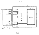
- FIG. 2 illustrates generally a block diagram of an MEMS gyroscope system 200 including an example digital, automatic gain control (AGC) circuit 201.
- the MEMS gyroscope system 200 can include a MEMS gyroscope 202 including a proof mass 203 such as a suspended proof mass, and a MEMS control circuit 204.
- the MEMS control circuit 204 can include a sense charge-to-voltage (C2V) converter 205, a phase shift circuit 206, a drive circuit 207, and the AGC circuit 201.
- C2V sense charge-to-voltage
- the AGC circuit 201 can provide a command signal to the drive circuit 207 to drive the proof mass 203 of the MEMS gyroscope 202 into oscillation at a resonant frequency of the proof mass 203.
- the proof mass 203 can have a resonant frequency at about 20kHz. It is understood that a proof mass can have a resonant frequency other than about 20kHz without departing from the scope of the present subject matter.
- the drive sense C2V 205 can be couple to drive sense electrodes (gp. gn) of the proof mass 203 of the MEMS gyroscope 202.
- the gn can provide a differential capacitive charge signal indicative of the actual oscillation of the proof mass 203.
- the differential capacitive charge signal can be used to provide phase and amplitude feedback to the drive circuit 207.
- a proof mass can include a single sense signal to provide a non-differential capacitive charge signal without departing from the scope of the present subject matter.
- the drive circuit 207 can provide a power control signal to vibrate the proof mass of the MEMS gyroscope.
- the drive circuit 207 can provide a power control signal to one or more proof mass drive electrodes (gdp. gdn) to vibrate the proof mass at a resonant frequency.
- the drive circuit 207 can provide a power control signal to one or more proof mass drive electrodes (gdp. gdn) to vibrate the proof mass using electrostatic actuation.
- the drive sense C2V converter 205 can provide capacitive sensed position information of the proof mass 203 as the proof mass 203 vibrates.
- a phase shift circuit 206 can introduce a phase shift of (90) degrees to the output of the drive sense C2V converter 205 to ensure oscillation (or vibration) of the proof mass 203. Accordingly, the drive circuit 207 can receive the phase shifted output from phase shift circuit 206 to drive the proof mass 203.
- a phase shift of 360 degrees can be achieve through a loop of the MEMS gyroscope system 200 to ensure oscillation of the proof mass 203.
- drive sense C2V converter 205 can provide 90 degrees of phase shift
- the phase shift circuit 206 can introduce a phase shift of 90 degrees
- the drive circuit can provide an inversion to ensure oscillation of proof mass 203.
- the output of the the drive sense C2V 205 can be used by the AGC circuit 201 to monitor and control the amplitude of the proof mass oscillations.
- FIG. 3 illustrates generally an example MEMS control circuit 304 including an example digital AGC circuit 301.
- the MEMS control circuit 204 can be coupled to a MEMS device, such as a MEMS gyroscope (not shown).
- the MEMS gyroscope can include a proof mass, drive electrodes, drive sense electrodes and sense electrodes (not shown).
- the MEMS control circuit 304 can include an analog section 311 and a digital AGC circuit 301.
- the analog section 311 can include, a drive sense C2V converter 305, an input analog-to-digital converter (ADC) 312, an output digital-to-analog converter (DAC) 313, a drive circuit 307 and a phase shift circuit 306 coupled between the drive circuit 307 and the output of the drive sense C2V converter 305.
- ADC analog-to-digital converter
- DAC digital-to-analog converter
- the drive sense C2V converter 305 can receive a capacitive signal from drive sense electrodes of the MEMS gyroscope and provide a voltage signal indicative of the capacitive signal.
- the voltage signal can be used to provide position information of the proof mass, such as phase and amplitude feedback, to the drive circuit 307.
- the drive circuit 307 can provide a power signal to vibrate the proof mass of the MEMS gyroscope.
- the drive circuit 307 can vibrate the proof mass at a resonant frequency.
- the drive circuit can provide a power signal to vibrate the proof mass using electrostatic actuation.
- the drive sense C2V converter 305 can provide capacitive sensed position information of the proof mass as the proof mass vibrates.
- a phase shift circuit 306 can introduce a phase shift of 90 degrees to the output of the drive sense C2V converter 305 to ensure oscillation (or vibration) of the proof mass.
- the drive circuit 307 can receive the phase shifted output from phase shift circuit 306 to drive the proof mass.
- the phase shift circuit 306 can introduce a phase shift of 90 degrees relative to the motion of proof mass to provide a 180 degree shift to the drive circuit 307 needed to ensure oscillation of proof mass.
- the output of the the drive sense C2V 305 can be used by the digital AGC circuit 301 to monitor and control the amplitude of the proof mass oscillations.
- the digital AGC 301 of the MEMS control circuit 304 can include an input section 316, an output section 317, and a control section 318.
- the input section 316 can include the drive sense ADC 312 and various filters 319, 320 for providing a digitized the drive sense signal.
- the drive sense ADC 312 can include a band-pass delta-sigma ADC. It is understood that other types of ADC converters are possible without departing from the scope of the present subject matter.
- a band-pass sigma-delta ADC can provide simple digital conversion of a drive sense signal while avoiding 1/f noise.
- the input section 316 can include a sinc 5 filter 319 to down-sample a single-bit data stream output of the drive sense ADC 312 and provide a multi-bit representation of the single-bit data stream output of the drive sense ADC 312, and a band-pass filter 320 to remove much of the out-of-band noise of the band pass filtered input signal.
- the sinc 5 filter 319 can receive a single-bit data stream operating at a data rate of about 972 kHz.
- the band-pass filter 320 can operate at a lower date rate than the sinc 5 filter 319.
- the band-pass filter 320 can operate at a data rate that is about an eighth of the data rate of the sinc 5 filter 319.
- the band-pass filter 320 can have a bandwidth of about 500Hz.
- the input section 316 can include a digital amplitude detector 321 to detect a representation of the oscillation amplitude of the output signal of the band-pass filter 320.
- the digital amplitude detector 321 can include an absolute value (
- the digital amplitude detector 321 can include an x 2 digital amplitude detector that can be immune to non-idealities in sampling instant time (e.g. timing jitter) and, thus, reduce phase noise.
- control section 318 can receive a target amplitude set point (target), and can include a summing junction 322, an averaging filter 323, gain multiplier 324, and startup control logic 325.
- control section 318 can include a set point multiplier 326 to scale the target amplitude set point (target) for summing with the output of the digital amplitude detector 321 of the input section 316.
- the summing junction 322 can provide an error signal, such as an amplitude error signal or an oscillation amplitude error signal, indicative of a difference between the output of the digital amplitude detector 321 and the target amplitude set point (target).
- the averaging filter 323 can be used to filter high frequency noise from the error signal.
- the averaging filter 323 can include a finite impulse response (FIR) filter that can filter, or average, or smooth, the error signal over a given number of samples or sample periods.
- the averaging filter 323 can include a bit shift module 327 to scale the output of the averaging filter 323.
- the error signal can be multiplied, or amplified, by a gain (dig. gain) to provide a command signal for the proof mass drive circuit 307.
- the control section 318 can include an integral error gain module (not shown). In some example, the control section 318 does not include an integral error gain module to allow a simpler implementation. In certain examples that do not include an integral gain module, low frequency doublets that can take hundreds of ms to seconds to settle to its final value can be avoided.
- startup control logic 325 can be used to drive the proof mass during start-up, for example, when the error signal can be quite large.
- the startup control logic 325 can include a comparator 328 to compare the command signal to a AGC enable threshold (S T ). In an example, when the command signal exceeds the AGC threshold (S T ), the comparator 328 provides a control signal (start_en) to have the drive circuit 307 drive the proof mass using a predetermined drive signal, such as a predetermined drive signal waveform.
- the control signal (start_en) of the start-up control logic 325 can be received by the drive circuit 307 such that the drive circuit 307 drives the proof mass using the predetermined drive signal.
- the predetermined drive signal can include a square wave waveform at a predetermined frequency.
- the phase shift circuit 306 can provide one or more template waveforms to the drive circuit 307, such as a sinusoidal waveform for AGC enabled amplitude control and the square waveform for start-up mode control.
- the control signal (start_en) of the start-up control logic 325 can transition to a second state.
- the drive circuit can drive the proof mass responsive to the command signal when the control signal (start_en) is in the second state.
- the drive circuit 307 can drive the proof mass using a sinusoidal waveform when the start signal (start_en) is in the second state.
- absence of an integral error gain component to the command signal can avoid bang-bang oscillatory behavior that can appear when the system is slewing, and can allow smooth transition between start-up mode type drive control and AGC amplitude drive control mode that is responsive to the command signal.
- the output section 317 can split the command signal into a coarse gain output signal (coarse gain) using a coarse gain stage and a fine gain output signal using a fine gain stage.
- the fine gain stage can include a digital limiter 329, one or more digital up-samplers 330, 331, and a drive digital to analog converter (DAC), such as a sigma-delta ( ⁇ ) (DAC) 313 to provide a basic unit change of the command signal.
- the coarse gain stage can include a low pass filter 332 to receive the limited command signal and a gain control counter 333 that can increment and decrement when the truncated, filtered, command signal overshoots or under shoots the fine gain registers, respectively.
- the coarse gain stage can include a feedback or correction loop 334 that can increment/decrement the non-limited command signal by a predetermined value after a change in the coarse gain output, such that the truncated command signal is not left at a maximum or minimum transition edge after a coarse gain change.
- the coarse gain output (coarse gain) can be updated at a slower rate than the fine gain output.
- a drive circuit 307 can receive the coarse gain output (coarse gain) and the fine gain output and can adjust a drive signal coupled to the proof mass in response to the received coarse and fine gain output signals.
- the digital AGC circuit 301 can be implemented on a single integrated circuit. In some examples, the digital AGC circuit 301 can be implemented on a single integrated circuit and can include one or more of the ⁇ ADC and the ⁇ DAC. In an example, the digital AGC circuit 301 can reduce noise in the output gain signals by executing a significant portion of the input stage, output stage and control stage in a digital environment.
- an apparatus can include a driver configured to oscillate a proof mass of a MEMS gyroscope, a charge-to-voltage (C2V) converter configured to receive a sense signal from a MEMS gyroscope and to provide oscillation information of the proof mass, an analog-to-digital converter (ADC) configured to receive the oscillation information of the proof mass and to provide a digital representation of the oscillation information, and a digital, automatic gain control circuit configured to receive the digital representation of the oscillation information, to provide oscillation amplitude error information using a comparison of the oscillation information to target amplitude information, and to provide a digital drive command signal using an amplified representation of the oscillation amplitude error information.
- C2V charge-to-voltage
- ADC analog-to-digital converter
- ADC analog-to-digital converter
- a digital, automatic gain control circuit configured to receive the digital representation of the oscillation information, to provide oscillation amplitude error information using a comparison of the oscillation information to target ampli
- Example 2 the ADC of Example 1 optionally is configured to provide the digital representation of the sense signal using a single-bit data stream.
- Example 3 the digital, automatic gain control circuit of any one or more of Examples 1-2 optionally includes a down-sample module to receive the single-bit data stream and provide a second digital representation of the sense signal using a first multi-bit data stream.
- Example 4 the digital, automatic gain control circuit of any one or more of Examples 1-3 optionally includes a band pass filter configured to receive the first multi-bit data stream and provide a third digital representation of the sense signal using a second multi-bit data stream.
- a band pass filter configured to receive the first multi-bit data stream and provide a third digital representation of the sense signal using a second multi-bit data stream.
- Example 5 the digital, automatic gain control circuit of any one or more of Examples 1-4 optionally includes an amplitude detector configured to perform a square operation of the third digital representation of the sense signal to provide amplitude information of the sense signal.
- Example 6 the digital, automatic gain control circuit of any one or more of Examples 1-5 optionally includes a digital comparator configured to receive amplitude information and the target information and to provide the oscillation amplitude error information.
- Example 7 the digital, automatic gain control circuit of any one or more of Examples 1-6 optionally includes a finite impulse response filter configured to average the oscillation amplitude error information over a plurality of sample periods to provide a smoothed error signal.
- a finite impulse response filter configured to average the oscillation amplitude error information over a plurality of sample periods to provide a smoothed error signal.
- Example 8 the ADC of any one or more of Examples 1-7 optionally includes a band-pass, delta-sigma ADC.
- Example 9 the apparatus of any one or more of Examples 1-8 optionally includes a digital-to-analog converter configured to receive at least a portion of the digital drive command signal and to provide an analog command signal to the driver.
- a digital-to-analog converter configured to receive at least a portion of the digital drive command signal and to provide an analog command signal to the driver.
- the digital, automatic gain control circuit of any one or more of Examples 1-9 optionally includes an output stage, the output stage including a fine gain register configured to provide a basic unit of change of the digital drive command signal, a low pass filter, and a coarse gain counter configured to increment on overshoot of the fine gain register, to decrement on undershoot of the fine gain register, and to provide a correction to the amplified representation of the oscillation amplitude error information.
- the output stage including a fine gain register configured to provide a basic unit of change of the digital drive command signal, a low pass filter, and a coarse gain counter configured to increment on overshoot of the fine gain register, to decrement on undershoot of the fine gain register, and to provide a correction to the amplified representation of the oscillation amplitude error information.
- a method can include oscillating a proof mass of a MEMS gyroscope using a driver, receiving oscillation information of the proof mass using a charge-to-voltage converter, providing a digital representation of the oscillation information using an analog to digital converter, providing oscillation amplitude error information using a comparison of the oscillation information to target amplitude information, and a digital automatic gain control circuit, and providing a digital drive command signal using the oscillation amplitude error information and the digital automatic gain control circuit.
- Example 12 the providing a digital representation of any one or more of Examples 1-11 optionally includes providing a digital representation of the oscillation information using a using a single-bit data stream.
- Example 13 the method of any one or more of Examples 1-12 optionally includes down-sampling the single-bit data stream to provide a second digital representation of the oscillation information using a multi-bit data stream.
- Example 14 the method of of any one or more of Examples 1-13 optionally includes processing the first multi-bit data stream using a band-pass filter to provide a third digital representation of the oscillation information.
- Example 15 the method of any one or more of Examples 1-14 optionally includes receiving the third digital representation of the oscillation information at a amplitude detector of the digital automatic gain control circuit, and providing amplitude information of the oscillation information using the amplitude detector.
- Example 16 the method of any one or more of Examples 1-15 optionally includes comparing the amplitude information to the target information to provide the oscillation amplitude error information using a digital comparator of the digital automatic gain control circuit.
- Example 17 the method of any one or more of Examples 1-16 optionally includes averaging the oscillation amplitude error information over a predetermined number of samples using a finite impulse response filter to provide a smoothed error signal.
- Example 18 the method of any one or more of Examples 1-17 optionally includes converting the digital, drive command signal to an analog, drive command signal using an digital-to-analog converter, and receiving the analog command signal at the driver.
- Example 19 the method of any one or more of Examples 1-18 optionally includes receiving the amplified representation of the oscillation amplitude error information at an output stage of the digital automatic gain control circuit; processing the amplified representation of the oscillation amplitude error information using a digital limiter and one or more digital up-samplers to provide a fine portion of the digital drive command signal, and processing the amplified representation of the oscillation amplitude error information using a low pass filter and a gain control counter to provide a coarse portion of the digital drive command signal.
- Example 20 the processing the amplified representation of the oscillation amplitude error information using a low pass filter and a gain control counter of any one or more of Examples 1-18 optionally includes incrementing the gain control counter when the low pass filter overshoots; and decrementing the gain control counter when the low pass filter undershoots.
- Example 21 the processing the amplified representation of the oscillation amplitude error information using a low pass filter and a gain control counter of any one or more of Examples 1-20 optionally includes feeding back a correction to the amplified representation of the oscillation amplitude error information when a value of the gain control counter changes.
- Method examples described herein can be machine or computer-implemented at least in part. Some examples can include a computer-readable medium or machine-readable medium encoded with instructions operable to configure an electronic device to perform methods as described in the above examples.
- An implementation of such methods can include code, such as microcode, assembly language code, a higher-level language code, or the like. Such code can include computer readable instructions for performing various methods. The code may form portions of computer program products. Further, in an example, the code can be tangibly stored on one or more volatile, non-transitory, or non-volatile tangible computer-readable media, such as during execution or at other times.
- Examples of these tangible computer-readable media can include, but are not limited to, hard disks, removable magnetic disks, removable optical disks (e.g., compact disks and digital video disks), magnetic cassettes, memory cards or sticks, random access memories (RAMs), read only memories (ROMs), and the like.
Abstract
Description
- This application claims the benefit of priority under 35 U.S.C. 119(e) to
Opris et al., U.S. Provisional Patent Application Serial Number, 61/620,641 - This document discusses, among other things, apparatus and methods for digital automatic gain control for driving a MEMS device, such as a proof mass. In an example, an apparatus can include a driver configured to oscillate a proof mass of a MEMS device, a charge-to-voltage (C2V) converter configured to provide oscillation information of the proof mass, an analog-to-digital converter (ADC) configured to provide a digital representation of the oscillation information, and a digital, automatic gain control circuit to provide oscillation amplitude error information using a comparison of the oscillation information to target amplitude information, and to provide a digital drive command signal using an amplified representation of the oscillation amplitude error information.
- This overview is intended to provide a general overview of subject matter of the present patent application. It is not intended to provide an exclusive or exhaustive explanation of the invention. The detailed description is included to provide further information about the present patent application.
- In the drawings, which are not necessarily drawn to scale, like numerals may describe similar components in different views. Like numerals having different letter suffixes may represent different instances of similar components. The drawings illustrate generally, by way of example, but not by way of limitation, various embodiments discussed in the present document.
-
FIG. 1 illustrates an analog control circuit coupled to a MEMS gyroscope. -
FIG. 2 illustrates generally a block diagram of an example MEMS gyroscope system. -
FIG. 3 illustrates generally an example MEMS control circuit including an example digital automatic gain control (AGC) circuit. - MEMS gyroscopes provide motion detection and measurement signals using deflections of a vibrating proof mass. The deflections are caused by a combination of movement of the vibrating proof mass, for example a proof mass of a gyroscope, and resulting Coriolis forces. Robust performance of a MEMS gyroscope can depend on the stability of the proof mass oscillations. The present inventors have recognized automatic gain control (AGC) apparatus and methods for driving a proof mass to oscillate with a stable amplitude at a resonant frequency of the proof mass. In certain examples an AGC loop can adjust an electrostatic force pumping into a MEMS gyroscope through drive electrodes such that the mechanical oscillation amplitude of the proof mass of the gyroscope is observed and maintained at a programmable target value. In some examples, the AGC loop can include an architecture that allows sensing the oscillation of the proof mass with very low noise and processing of the loop operations can be completed in a noise-less, digital environment.
-
FIG. 1 illustrates ananalog control circuit 104 coupled to aMEMS gyroscope 102. TheMEMS gyroscope 102 can include drive electrodes (gdp, gdn) and drive sense electrodes (gp, gn) for coupling theanalog control circuit 104 to theMEMS gyroscope 102. Theanalog control circuit 104 can drive a proof mass of the MEMS gyroscope into oscillation using adriver circuit 107 coupled to the drive electrodes (gdp, gdn) of theMEMS gyroscope 102. Theanalog control circuit 104 can receive proof mass position information using the drive sense electrodes (gp, gn) of the MEMS gyroscope and a drive sense charge-to-voltage (C2V)converter 105 of theanalog control circuit 104. Aphase shifter 106 can provide phase shifted position information of the proof mass to aduty cycle generator 140 of theanalog control circuit 104 to generate a command signal for thedriver circuit 107. In certain examples, thephase shifter 106 can provide phase shift to sustained oscillation of the proof mass of theMEMS gyroscope 102. Ananalog peak detector 141 can also receive the proof mass position information and can provide amplitude information about the proof mass oscillations. Ananalog comparator 142 can compare the amplitude information to a desired amplitude reference (AREF), and can provide an amplitude error signal including amplitude error information, or oscillation amplitude error information. In some examples, theanalog comparator 142 can include a gain setting to scale the amplitude error signal. Afeedback loop 143 of theanalog control circuit 104 can use aloop compensation module 144 to further compensate the amplitude error information to assist theduty cycle generator 140 in generating a control signal for thedriver circuit 107. In response to the control signal, thedriver circuit 107 can drive the proof mass of theMEMS gyroscope 102 into oscillation at a resonant frequency and with stable oscillation amplitude. -
FIG. 2 illustrates generally a block diagram of anMEMS gyroscope system 200 including an example digital, automatic gain control (AGC)circuit 201. The MEMSgyroscope system 200 can include aMEMS gyroscope 202 including aproof mass 203 such as a suspended proof mass, and aMEMS control circuit 204. In certain examples, theMEMS control circuit 204 can include a sense charge-to-voltage (C2V)converter 205, aphase shift circuit 206, adrive circuit 207, and theAGC circuit 201. TheAGC circuit 201 can provide a command signal to thedrive circuit 207 to drive theproof mass 203 of theMEMS gyroscope 202 into oscillation at a resonant frequency of theproof mass 203. In certain examples, theproof mass 203 can have a resonant frequency at about 20kHz. It is understood that a proof mass can have a resonant frequency other than about 20kHz without departing from the scope of the present subject matter. Thedrive sense C2V 205 can be couple to drive sense electrodes (gp. gn) of theproof mass 203 of theMEMS gyroscope 202. The drive sense electrodes (gp. gn) can provide a differential capacitive charge signal indicative of the actual oscillation of theproof mass 203. The differential capacitive charge signal can be used to provide phase and amplitude feedback to thedrive circuit 207. It is understood that a proof mass can include a single sense signal to provide a non-differential capacitive charge signal without departing from the scope of the present subject matter. In certain examples, thedrive circuit 207 can provide a power control signal to vibrate the proof mass of the MEMS gyroscope. In some examples, thedrive circuit 207 can provide a power control signal to one or more proof mass drive electrodes (gdp. gdn) to vibrate the proof mass at a resonant frequency. In some examples, thedrive circuit 207 can provide a power control signal to one or more proof mass drive electrodes (gdp. gdn) to vibrate the proof mass using electrostatic actuation. In certain examples, the drivesense C2V converter 205 can provide capacitive sensed position information of theproof mass 203 as theproof mass 203 vibrates. In an example, aphase shift circuit 206 can introduce a phase shift of (90) degrees to the output of the drivesense C2V converter 205 to ensure oscillation (or vibration) of theproof mass 203. Accordingly, thedrive circuit 207 can receive the phase shifted output fromphase shift circuit 206 to drive theproof mass 203. In certain examples, a phase shift of 360 degrees can be achieve through a loop of theMEMS gyroscope system 200 to ensure oscillation of theproof mass 203. In an example, drivesense C2V converter 205 can provide 90 degrees of phase shift, thephase shift circuit 206 can introduce a phase shift of 90 degrees, and the drive circuit can provide an inversion to ensure oscillation ofproof mass 203. In certain examples, the output of the thedrive sense C2V 205 can be used by theAGC circuit 201 to monitor and control the amplitude of the proof mass oscillations. -
FIG. 3 illustrates generally an exampleMEMS control circuit 304 including an exampledigital AGC circuit 301. In certain examples, theMEMS control circuit 204 can be coupled to a MEMS device, such as a MEMS gyroscope (not shown). In certain examples, the MEMS gyroscope can include a proof mass, drive electrodes, drive sense electrodes and sense electrodes (not shown). In certain examples, theMEMS control circuit 304 can include ananalog section 311 and adigital AGC circuit 301. In certain examples, theanalog section 311 can include, a drivesense C2V converter 305, an input analog-to-digital converter (ADC) 312, an output digital-to-analog converter (DAC) 313, adrive circuit 307 and aphase shift circuit 306 coupled between thedrive circuit 307 and the output of the drivesense C2V converter 305. - In certain examples, the drive
sense C2V converter 305 can receive a capacitive signal from drive sense electrodes of the MEMS gyroscope and provide a voltage signal indicative of the capacitive signal. The voltage signal can be used to provide position information of the proof mass, such as phase and amplitude feedback, to thedrive circuit 307. In certain examples, thedrive circuit 307 can provide a power signal to vibrate the proof mass of the MEMS gyroscope. In some examples, thedrive circuit 307 can vibrate the proof mass at a resonant frequency. In some examples, the drive circuit can provide a power signal to vibrate the proof mass using electrostatic actuation. In certain examples, the drivesense C2V converter 305 can provide capacitive sensed position information of the proof mass as the proof mass vibrates. In an example, aphase shift circuit 306 can introduce a phase shift of 90 degrees to the output of the drivesense C2V converter 305 to ensure oscillation (or vibration) of the proof mass. Accordingly, thedrive circuit 307 can receive the phase shifted output fromphase shift circuit 306 to drive the proof mass. In such an example, thephase shift circuit 306 can introduce a phase shift of 90 degrees relative to the motion of proof mass to provide a 180 degree shift to thedrive circuit 307 needed to ensure oscillation of proof mass. In certain examples, the output of the thedrive sense C2V 305 can be used by thedigital AGC circuit 301 to monitor and control the amplitude of the proof mass oscillations. - In certain examples, the
digital AGC 301 of theMEMS control circuit 304 can include aninput section 316, anoutput section 317, and acontrol section 318. - In certain examples, the
input section 316 can include thedrive sense ADC 312 andvarious filters drive sense ADC 312 can include a band-pass delta-sigma ADC. It is understood that other types of ADC converters are possible without departing from the scope of the present subject matter. In certain examples, a band-pass sigma-delta ADC can provide simple digital conversion of a drive sense signal while avoiding 1/f noise. In certain examples, theinput section 316 can include a sinc5 filter 319 to down-sample a single-bit data stream output of thedrive sense ADC 312 and provide a multi-bit representation of the single-bit data stream output of thedrive sense ADC 312, and a band-pass filter 320 to remove much of the out-of-band noise of the band pass filtered input signal. In an example, the sinc5 filter 319 can receive a single-bit data stream operating at a data rate of about 972 kHz. In an example, the band-pass filter 320 can operate at a lower date rate than the sinc5 filter 319. In certain examples, the band-pass filter 320 can operate at a data rate that is about an eighth of the data rate of the sinc5 filter 319. In some examples, the band-pass filter 320 can have a bandwidth of about 500Hz. In certain examples, theinput section 316 can include adigital amplitude detector 321 to detect a representation of the oscillation amplitude of the output signal of the band-pass filter 320. In some examples, thedigital amplitude detector 321 can include an absolute value (|x|) amplitude detector. In an example, thedigital amplitude detector 321 can include an x2 digital amplitude detector that can be immune to non-idealities in sampling instant time (e.g. timing jitter) and, thus, reduce phase noise. - In certain examples, the
control section 318 can receive a target amplitude set point (target), and can include a summingjunction 322, an averagingfilter 323,gain multiplier 324, andstartup control logic 325. In certain examples, thecontrol section 318 can include aset point multiplier 326 to scale the target amplitude set point (target) for summing with the output of thedigital amplitude detector 321 of theinput section 316. In certain examples, the summingjunction 322 can provide an error signal, such as an amplitude error signal or an oscillation amplitude error signal, indicative of a difference between the output of thedigital amplitude detector 321 and the target amplitude set point (target). In certain examples, the averagingfilter 323 can be used to filter high frequency noise from the error signal. In some examples, the averagingfilter 323 can include a finite impulse response (FIR) filter that can filter, or average, or smooth, the error signal over a given number of samples or sample periods. In certain examples, the averagingfilter 323 can include abit shift module 327 to scale the output of the averagingfilter 323. In certain examples, the error signal can be multiplied, or amplified, by a gain (dig. gain) to provide a command signal for the proofmass drive circuit 307. In some examples, thecontrol section 318 can include an integral error gain module (not shown). In some example, thecontrol section 318 does not include an integral error gain module to allow a simpler implementation. In certain examples that do not include an integral gain module, low frequency doublets that can take hundreds of ms to seconds to settle to its final value can be avoided. - In some examples,
startup control logic 325 can be used to drive the proof mass during start-up, for example, when the error signal can be quite large. In certain examples, thestartup control logic 325 can include acomparator 328 to compare the command signal to a AGC enable threshold (ST). In an example, when the command signal exceeds the AGC threshold (ST), thecomparator 328 provides a control signal (start_en) to have thedrive circuit 307 drive the proof mass using a predetermined drive signal, such as a predetermined drive signal waveform. In an example, the control signal (start_en) of the start-upcontrol logic 325 can be received by thedrive circuit 307 such that thedrive circuit 307 drives the proof mass using the predetermined drive signal. In certain examples, the predetermined drive signal can include a square wave waveform at a predetermined frequency. In certain examples, thephase shift circuit 306 can provide one or more template waveforms to thedrive circuit 307, such as a sinusoidal waveform for AGC enabled amplitude control and the square waveform for start-up mode control. When the command signal shrinks such that it does not exceed the AGC enable threshold (ST), the control signal (start_en) of the start-upcontrol logic 325 can transition to a second state. In certain examples, the drive circuit can drive the proof mass responsive to the command signal when the control signal (start_en) is in the second state. In certain examples, thedrive circuit 307 can drive the proof mass using a sinusoidal waveform when the start signal (start_en) is in the second state. In some examples, absence of an integral error gain component to the command signal can avoid bang-bang oscillatory behavior that can appear when the system is slewing, and can allow smooth transition between start-up mode type drive control and AGC amplitude drive control mode that is responsive to the command signal. - In certain examples, the
output section 317 can split the command signal into a coarse gain output signal (coarse gain) using a coarse gain stage and a fine gain output signal using a fine gain stage. The fine gain stage can include adigital limiter 329, one or more digital up-samplers gain control counter 333 that can increment and decrement when the truncated, filtered, command signal overshoots or under shoots the fine gain registers, respectively. In certain examples, the coarse gain stage can include a feedback orcorrection loop 334 that can increment/decrement the non-limited command signal by a predetermined value after a change in the coarse gain output, such that the truncated command signal is not left at a maximum or minimum transition edge after a coarse gain change. In certain examples, the coarse gain output (coarse gain) can be updated at a slower rate than the fine gain output. In certain examples, adrive circuit 307 can receive the coarse gain output (coarse gain) and the fine gain output and can adjust a drive signal coupled to the proof mass in response to the received coarse and fine gain output signals. - In various examples, the
digital AGC circuit 301 can be implemented on a single integrated circuit. In some examples, thedigital AGC circuit 301 can be implemented on a single integrated circuit and can include one or more of the ΔΣ ADC and the ΣΔ DAC. In an example, thedigital AGC circuit 301 can reduce noise in the output gain signals by executing a significant portion of the input stage, output stage and control stage in a digital environment. - In Example 1, an apparatus can include a driver configured to oscillate a proof mass of a MEMS gyroscope, a charge-to-voltage (C2V) converter configured to receive a sense signal from a MEMS gyroscope and to provide oscillation information of the proof mass, an analog-to-digital converter (ADC) configured to receive the oscillation information of the proof mass and to provide a digital representation of the oscillation information, and a digital, automatic gain control circuit configured to receive the digital representation of the oscillation information, to provide oscillation amplitude error information using a comparison of the oscillation information to target amplitude information, and to provide a digital drive command signal using an amplified representation of the oscillation amplitude error information.
- In Example 2, the ADC of Example 1 optionally is configured to provide the digital representation of the sense signal using a single-bit data stream.
- In Example 3, the digital, automatic gain control circuit of any one or more of Examples 1-2 optionally includes a down-sample module to receive the single-bit data stream and provide a second digital representation of the sense signal using a first multi-bit data stream.
- In Example 4, the digital, automatic gain control circuit of any one or more of Examples 1-3 optionally includes a band pass filter configured to receive the first multi-bit data stream and provide a third digital representation of the sense signal using a second multi-bit data stream.
- In Example 5, the digital, automatic gain control circuit of any one or more of Examples 1-4 optionally includes an amplitude detector configured to perform a square operation of the third digital representation of the sense signal to provide amplitude information of the sense signal.
- In Example 6, the digital, automatic gain control circuit of any one or more of Examples 1-5 optionally includes a digital comparator configured to receive amplitude information and the target information and to provide the oscillation amplitude error information.
- In Example 7, the digital, automatic gain control circuit of any one or more of Examples 1-6 optionally includes a finite impulse response filter configured to average the oscillation amplitude error information over a plurality of sample periods to provide a smoothed error signal.
- In Example 8, the ADC of any one or more of Examples 1-7 optionally includes a band-pass, delta-sigma ADC.
- In Example 9, the apparatus of any one or more of Examples 1-8 optionally includes a digital-to-analog converter configured to receive at least a portion of the digital drive command signal and to provide an analog command signal to the driver.
- In Example 10, the digital, automatic gain control circuit of any one or more of Examples 1-9 optionally includes an output stage, the output stage including a fine gain register configured to provide a basic unit of change of the digital drive command signal, a low pass filter, and a coarse gain counter configured to increment on overshoot of the fine gain register, to decrement on undershoot of the fine gain register, and to provide a correction to the amplified representation of the oscillation amplitude error information.
- In Example 11, a method can include oscillating a proof mass of a MEMS gyroscope using a driver, receiving oscillation information of the proof mass using a charge-to-voltage converter, providing a digital representation of the oscillation information using an analog to digital converter, providing oscillation amplitude error information using a comparison of the oscillation information to target amplitude information, and a digital automatic gain control circuit, and providing a digital drive command signal using the oscillation amplitude error information and the digital automatic gain control circuit.
- In Example 12, the providing a digital representation of any one or more of Examples 1-11 optionally includes providing a digital representation of the oscillation information using a using a single-bit data stream.
- In Example 13, the method of any one or more of Examples 1-12 optionally includes down-sampling the single-bit data stream to provide a second digital representation of the oscillation information using a multi-bit data stream.
- In Example 14, the method of of any one or more of Examples 1-13 optionally includes processing the first multi-bit data stream using a band-pass filter to provide a third digital representation of the oscillation information.
- In Example 15, the method of any one or more of Examples 1-14 optionally includes receiving the third digital representation of the oscillation information at a amplitude detector of the digital automatic gain control circuit, and providing amplitude information of the oscillation information using the amplitude detector.
- In Example 16, the method of any one or more of Examples 1-15 optionally includes comparing the amplitude information to the target information to provide the oscillation amplitude error information using a digital comparator of the digital automatic gain control circuit..
- In Example 17, the method of any one or more of Examples 1-16 optionally includes averaging the oscillation amplitude error information over a predetermined number of samples using a finite impulse response filter to provide a smoothed error signal.
- In Example 18, the method of any one or more of Examples 1-17 optionally includes converting the digital, drive command signal to an analog, drive command signal using an digital-to-analog converter, and receiving the analog command signal at the driver.
- In Example 19, the method of any one or more of Examples 1-18 optionally includes receiving the amplified representation of the oscillation amplitude error information at an output stage of the digital automatic gain control circuit; processing the amplified representation of the oscillation amplitude error information using a digital limiter and one or more digital up-samplers to provide a fine portion of the digital drive command signal, and processing the amplified representation of the oscillation amplitude error information using a low pass filter and a gain control counter to provide a coarse portion of the digital drive command signal.
- In Example 20, the processing the amplified representation of the oscillation amplitude error information using a low pass filter and a gain control counter of any one or more of Examples 1-18 optionally includes incrementing the gain control counter when the low pass filter overshoots; and decrementing the gain control counter when the low pass filter undershoots.
- In Example 21, the processing the amplified representation of the oscillation amplitude error information using a low pass filter and a gain control counter of any one or more of Examples 1-20 optionally includes feeding back a correction to the amplified representation of the oscillation amplitude error information when a value of the gain control counter changes.
- The above detailed description includes references to the accompanying drawings, which form a part of the detailed description. The drawings show, by way of illustration, specific embodiments in which the invention can be practiced. These embodiments are also referred to herein as "examples." Such examples can include elements in addition to those shown or described. However, the present inventors also contemplate examples in which only those elements shown or described are provided. Moreover, the present inventors also contemplate examples using any combination or permutation of those elements shown or described (or one or more aspects thereof), either with respect to a particular example (or one or more aspects thereof), or with respect to other examples (or one or more aspects thereof) shown or described herein.
- All publications, patents, and patent documents referred to in this document are incorporated by reference herein in their entirety, as though individually incorporated by reference. In the event of inconsistent usages between this document and those documents so incorporated by reference, the usage in the incorporated reference(s) should be considered supplementary to that of this document; for irreconcilable inconsistencies, the usage in this document controls.
- In this document, the terms "a" or "an" are used, as is common in patent documents, to include one or more than one, independent of any other instances or usages of "at least one" or "one or more." In this document, the term "or" is used to refer to a nonexclusive or, such that "A or B" includes "A but not B," "B but not A," and "A and B," unless otherwise indicated. In this document, the terms "including" and "in which" are used as the plain-English equivalents of the respective terms "comprising" and "wherein." Also, in the following claims, the terms "including" and "comprising" are open-ended, that is, a system, device, article, or process that includes elements in addition to those listed after such a term in a claim are still deemed to fall within the scope of that claim. Moreover, in the following claims, the terms "first," "second," and "third," etc. are used merely as labels, and are not intended to impose numerical requirements on their objects.
- Method examples described herein can be machine or computer-implemented at least in part. Some examples can include a computer-readable medium or machine-readable medium encoded with instructions operable to configure an electronic device to perform methods as described in the above examples. An implementation of such methods can include code, such as microcode, assembly language code, a higher-level language code, or the like. Such code can include computer readable instructions for performing various methods. The code may form portions of computer program products. Further, in an example, the code can be tangibly stored on one or more volatile, non-transitory, or non-volatile tangible computer-readable media, such as during execution or at other times. Examples of these tangible computer-readable media can include, but are not limited to, hard disks, removable magnetic disks, removable optical disks (e.g., compact disks and digital video disks), magnetic cassettes, memory cards or sticks, random access memories (RAMs), read only memories (ROMs), and the like.
- The above description is intended to be illustrative, and not restrictive. For example, the above-described examples (or one or more aspects thereof) may be used in combination with each other. Other embodiments can be used, such as by one of ordinary skill in the art upon reviewing the above description. The Abstract is provided to comply with 37 C.F.R. § 1.72(b), to allow the reader to quickly ascertain the nature of the technical disclosure. It is submitted with the understanding that it will not be used to interpret or limit the scope or meaning of the claims. Also, in the above Detailed Description, various features may be grouped together to streamline the disclosure. This should not be interpreted as intending that an unclaimed disclosed feature is essential to any claim. Rather, inventive subject matter may lie in less than all features of a particular disclosed embodiment. Thus, the following claims are hereby incorporated into the Detailed Description, with each claim standing on its own as a separate embodiment, and it is contemplated that such embodiments can be combined with each other in various combinations or permutations. The scope of the invention should be determined with reference to the appended claims, along with the full scope of equivalents to which such claims are entitled.
Claims (13)
- An apparatus comprising:a driver configured to oscillate a proof mass of a MEMS gyroscope;a charge-to-voltage (C2V) converter configured to receive a sense signal from a MEMS gyroscope and to provide oscillation information of the proof mass;an analog-to-digital converter (ADC) configured to receive the oscillation information of the proof mass and to provide a digital representation of the oscillation information; anda digital, automatic gain control circuit configured to receive the digital representation of the oscillation information, to provide oscillation amplitude error information using a comparison of the oscillation information to target amplitude information, and to provide a digital drive command signal using an amplified representation of the oscillation amplitude error information.
- The apparatus of claim 1, wherein the ADC is configured to provide the digital representation of the sense signal using a single-bit data stream, and wherein the digital, automatic gain control circuit includes a down-sample module to receive the single-bit data stream and provide a second digital representation of the sense signal using a first multi-bit data stream.
- The apparatus of claim 2, wherein the digital, automatic gain control circuit includes a band pass filter configured to receive the first multi-bit data stream and provide a third digital representation of the sense signal using a second multi-bit data stream and wherein the digital, automatic gain control circuit includes an amplitude detector configured to perform a square operation of the third digital representation of the sense signal to provide amplitude information of the sense signal.
- The apparatus of claim 3, wherein the digital, automatic gain control circuit includes a digital comparator configured to receive amplitude information and the target information and to provide the oscillation amplitude error information, and wherein the digital, automatic gain control circuit includes a finite impulse response filter configured to average the oscillation amplitude error information over a plurality of sample periods to provide a smoothed error signal.
- The apparatus of claim 1, including a digital-to-analog converter configured to receive at least a portion of the digital drive command signal and to provide an analog command signal to the driver.
- The apparatus of claim 1, wherein the digital, automatic gain control circuit includes an output stage, the output stage including:a fine gain register configured to provide a basic unit of change of the digital drive command signal;a low pass filter; anda coarse gain counter configured to increment on overshoot of the fine gain register, to decrement on undershoot of the fine gain register, and to provide a correction to the amplified representation of the oscillation amplitude error information.
- A method comprising:oscillating a proof mass of a MEMS gyroscope using a driver;receiving oscillation information of the proof mass using a charge-to-voltage converter;providing a digital representation of the oscillation information using an analog to digital converter;providing oscillation amplitude error information using a comparison of the oscillation information to target amplitude information, and a digital automatic gain control circuit; andproviding a digital drive command signal using the oscillation amplitude error information and the digital automatic gain control circuit.
- The method of claim 7, wherein providing a digital representation includes providing a digital representation of the oscillation information using a using a single-bit data stream.
- The method of claim 8, including down-sampling the single-bit data stream to provide a second digital representation of the oscillation information using a multi-bit data stream.
- The method of claim 9, including:processing the first multi-bit data stream using a band-pass filter to provide a third digital representation of the oscillation information;receiving the third digital representation of the oscillation information at a amplitude detector of the digital automatic gain control circuit;providing amplitude information of the oscillation information using the amplitude detector;comparing the amplitude information to the target information to provide the oscillation amplitude error information using a digital comparator of the digital automatic gain control circuit; andaveraging the oscillation amplitude error information over a predetermined number of samples using a finite impulse response filter to provide a smoothed error signal.
- The method of claim 7 including:receiving an amplified representation of the oscillation amplitude error information at an output stage of the digital automatic gain control circuit;processing the amplified representation of the oscillation amplitude error information using a digital limiter and one or more digital up-samplers to provide a fine portion of the digital drive command signal; andprocessing the amplified representation of the oscillation amplitude error information using a low pass filter and a gain control counter to provide a coarse portion of the digital drive command signal.
- The method of claim 11, wherein processing the amplified representation of the oscillation amplitude error information using a low pass filter and a gain control counter includes incrementing the gain control counter when the low pass filter overshoots; and decrementing the gain control counter when the low pass filter undershoots.
- The method of claim 12, wherein processing the amplified representation of the oscillation amplitude error information using a low pass filter and a gain control counter includes feeding back a correction to the amplified representation of the oscillation amplitude error information when a value of the gain control counter changes.
Applications Claiming Priority (1)
| Application Number | Priority Date | Filing Date | Title |
|---|---|---|---|
| US201261620641P | 2012-04-05 | 2012-04-05 |
Publications (3)
| Publication Number | Publication Date |
|---|---|
| EP2647952A2 true EP2647952A2 (en) | 2013-10-09 |
| EP2647952A3 EP2647952A3 (en) | 2015-09-23 |
| EP2647952B1 EP2647952B1 (en) | 2017-11-15 |
Family
ID=48045249
Family Applications (1)
| Application Number | Title | Priority Date | Filing Date |
|---|---|---|---|
| EP13001720.5A Active EP2647952B1 (en) | 2012-04-05 | 2013-04-04 | Mems device automatic-gain control loop for mechanical amplitude drive |
Country Status (4)
| Country | Link |
|---|---|
| US (1) | US9618361B2 (en) |
| EP (1) | EP2647952B1 (en) |
| KR (1) | KR102056092B1 (en) |
| CN (2) | CN103363983B (en) |
Cited By (3)
| Publication number | Priority date | Publication date | Assignee | Title |
|---|---|---|---|---|
| CN109506639A (en) * | 2017-09-14 | 2019-03-22 | 意法半导体股份有限公司 | Driving circuit, the method for driving MEMS gyroscope and corresponding MEMS gyroscope |
| CN111780736A (en) * | 2020-05-28 | 2020-10-16 | 深迪半导体(上海)有限公司 | Micro-mechanical structure driving amplitude correction system and method |
| CN112146637A (en) * | 2020-08-24 | 2020-12-29 | 南京理工大学 | Full-angle mode circuit gain error self-compensation system of micro-electromechanical gyroscope |
Families Citing this family (41)
| Publication number | Priority date | Publication date | Assignee | Title |
|---|---|---|---|---|
| US8710599B2 (en) | 2009-08-04 | 2014-04-29 | Fairchild Semiconductor Corporation | Micromachined devices and fabricating the same |
| CN103238075B (en) | 2010-09-18 | 2015-11-25 | 快捷半导体公司 | There is the micromechanics triaxial accelerometer of single mass |
| US9278845B2 (en) | 2010-09-18 | 2016-03-08 | Fairchild Semiconductor Corporation | MEMS multi-axis gyroscope Z-axis electrode structure |
| US9352961B2 (en) | 2010-09-18 | 2016-05-31 | Fairchild Semiconductor Corporation | Flexure bearing to reduce quadrature for resonating micromachined devices |
| EP2616771B8 (en) | 2010-09-18 | 2018-12-19 | Fairchild Semiconductor Corporation | Micromachined monolithic 6-axis inertial sensor |
| CN103221333B (en) | 2010-09-18 | 2017-05-31 | 快捷半导体公司 | Multi-die MEMS package |
| KR20130052652A (en) | 2010-09-18 | 2013-05-22 | 페어차일드 세미컨덕터 코포레이션 | Sealed packaging for microelectromechanical systems |
| KR101332701B1 (en) | 2010-09-20 | 2013-11-25 | 페어차일드 세미컨덕터 코포레이션 | Microelectromechanical pressure sensor including reference capacitor |
| KR101311966B1 (en) | 2010-09-20 | 2013-10-14 | 페어차일드 세미컨덕터 코포레이션 | Through silicon via with reduced shunt capacitance |
| US9062972B2 (en) | 2012-01-31 | 2015-06-23 | Fairchild Semiconductor Corporation | MEMS multi-axis accelerometer electrode structure |
| US8978475B2 (en) | 2012-02-01 | 2015-03-17 | Fairchild Semiconductor Corporation | MEMS proof mass with split z-axis portions |
| US9488693B2 (en) | 2012-04-04 | 2016-11-08 | Fairchild Semiconductor Corporation | Self test of MEMS accelerometer with ASICS integrated capacitors |
| EP2647952B1 (en) * | 2012-04-05 | 2017-11-15 | Fairchild Semiconductor Corporation | Mems device automatic-gain control loop for mechanical amplitude drive |
| EP2647955B8 (en) | 2012-04-05 | 2018-12-19 | Fairchild Semiconductor Corporation | MEMS device quadrature phase shift cancellation |
| US9069006B2 (en) | 2012-04-05 | 2015-06-30 | Fairchild Semiconductor Corporation | Self test of MEMS gyroscope with ASICs integrated capacitors |
| EP2648334B1 (en) | 2012-04-05 | 2020-06-10 | Fairchild Semiconductor Corporation | Mems device front-end charge amplifier |
| KR101999745B1 (en) | 2012-04-12 | 2019-10-01 | 페어차일드 세미컨덕터 코포레이션 | Micro-electro-mechanical-system(mems) driver |
| US9625272B2 (en) | 2012-04-12 | 2017-04-18 | Fairchild Semiconductor Corporation | MEMS quadrature cancellation and signal demodulation |
| DE102013014881B4 (en) | 2012-09-12 | 2023-05-04 | Fairchild Semiconductor Corporation | Enhanced silicon via with multi-material fill |
| US9759564B2 (en) | 2013-03-15 | 2017-09-12 | Fairchild Semiconductor Corporation | Temperature and power supply calibration |
| US9835647B2 (en) | 2014-03-18 | 2017-12-05 | Fairchild Semiconductor Corporation | Apparatus and method for extending analog front end sense range of a high-Q MEMS sensor |
| CN105333886B (en) | 2014-06-26 | 2018-04-06 | 无锡华润上华科技有限公司 | Correct the method and system of gyro sensor drive amplitude |
| DE102014010056B4 (en) * | 2014-07-07 | 2016-02-25 | Northrop Grumman Litef Gmbh | A control device and method for minimizing scale factor errors of a rotation rate sensor |
| CN104390637A (en) * | 2014-11-18 | 2015-03-04 | 中国兵器工业集团第二一四研究所苏州研发中心 | Small-sized anti-high-overload digital micro-electro-mechanical system (MEMS) gyroscope sensor |
| US10200794B2 (en) * | 2014-12-31 | 2019-02-05 | Invensense, Inc. | Ultrasonic operation of a digital microphone |
| US10571267B1 (en) * | 2015-09-01 | 2020-02-25 | Hrl Laboratories, Llc | High stability angular sensor |
| US10277821B2 (en) * | 2016-04-19 | 2019-04-30 | Semiconductor Components Industries, Llc | Methods and apparatus for optical image stabilization |
| US10365104B2 (en) * | 2016-05-11 | 2019-07-30 | Murata Manufacturing Co., Ltd. | Digital controller for a MEMS gyroscope |
| WO2018148615A1 (en) * | 2017-02-11 | 2018-08-16 | Mumec, Inc. | Super-regenerative transceiver with improved frequency discrimination |
| CN107132763B (en) * | 2017-05-11 | 2019-12-03 | 北方电子研究院安徽有限公司 | A kind of MEMS gyroscope close-loop driven automatic gain control circuit |
| US20180335458A1 (en) * | 2017-05-18 | 2018-11-22 | Cirrus Logic International Semiconductor Ltd. | Capacitance sensor |
| KR101910420B1 (en) | 2017-05-25 | 2018-10-22 | 다믈멀티미디어주식회사 | Driving device for gyroscope system |
| US11466986B2 (en) * | 2017-12-14 | 2022-10-11 | Invensense, Inc. | Microelectromechanical systems (MEMS) gyroscope sense frequency tracking |
| US11150331B2 (en) * | 2018-07-06 | 2021-10-19 | Infineon Technologies Ag | Detection and compensation of MEMS oscillating structure asymmetries and periodic jitters |
| CN109540176B (en) * | 2018-12-24 | 2022-08-05 | 中国航空工业集团公司西安飞行自动控制研究所 | Silicon micro gyroscope Sigma Delta detection closed-loop control system structure and parameter setting method |
| JP7127577B2 (en) * | 2019-02-26 | 2022-08-30 | 株式会社デンソー | physical quantity detector |
| US11255670B2 (en) | 2019-06-26 | 2022-02-22 | Stmicroelectronics, Inc. | MEMS gyroscope self-test using a technique for deflection of the sensing mobile mass |
| US11162790B2 (en) * | 2019-06-26 | 2021-11-02 | Stmicroelectronics, Inc. | MEMS gyroscope start-up process and circuit |
| US11320452B2 (en) | 2019-06-26 | 2022-05-03 | Stmicroelectronics, Inc. | MEMS accelerometer self-test using an active mobile mass deflection technique |
| US11175138B2 (en) | 2019-06-26 | 2021-11-16 | Stmicroelectronics, Inc. | MEMS gyroscope control circuit |
| CN111327326B (en) * | 2020-04-24 | 2023-09-19 | 杭州思泰微电子有限公司 | Signal amplitude correction method for analog-to-digital converter |
Family Cites Families (337)
| Publication number | Priority date | Publication date | Assignee | Title |
|---|---|---|---|---|
| US3231729A (en) | 1961-03-31 | 1966-01-25 | Systems Inc Comp | Dynamic storage analog computer |
| US4511848A (en) | 1983-06-15 | 1985-04-16 | Watson Industries, Inc. | Synchronous AM demodulator with quadrature signal cancellation |
| US5354695A (en) | 1992-04-08 | 1994-10-11 | Leedy Glenn J | Membrane dielectric isolation IC fabrication |
| US4896156A (en) | 1988-10-03 | 1990-01-23 | General Electric Company | Switched-capacitance coupling networks for differential-input amplifiers, not requiring balanced input signals |
| TW520072U (en) | 1991-07-08 | 2003-02-01 | Samsung Electronics Co Ltd | A semiconductor device having a multi-layer metal contact |
| DK195991A (en) | 1991-12-04 | 1993-06-05 | Jeppe Forchhammer | MODIFIED & SUPPLEMENTARY DEVICE SECURITY / MONITORING DEVICES |
| EP0547742B1 (en) | 1991-12-19 | 1995-12-13 | Motorola, Inc. | Triaxial accelerometer |
| US5491604A (en) | 1992-12-11 | 1996-02-13 | The Regents Of The University Of California | Q-controlled microresonators and tunable electronic filters using such resonators |
| FR2700003B1 (en) | 1992-12-28 | 1995-02-10 | Commissariat Energie Atomique | Method for manufacturing a pressure sensor using silicon on insulator technology and sensor obtained. |
| JP2569293B2 (en) | 1993-07-24 | 1997-01-08 | エンドレス ウント ハウザー ゲゼルシャフト ミット ベシュレンクテル ハフツング ウント コンパニー | Capacitive pressure sensor with high linearity |
| US5426970A (en) | 1993-08-02 | 1995-06-27 | New Sd, Inc. | Rotation rate sensor with built in test circuit |
| US5481914A (en) | 1994-03-28 | 1996-01-09 | The Charles Stark Draper Laboratory, Inc. | Electronics for coriolis force and other sensors |
| US5703292A (en) | 1994-03-28 | 1997-12-30 | The Charles Stark Draper Laboratory, Inc. | Sensor having an off-frequency drive scheme and a sense bias generator utilizing tuned circuits |
| US5765046A (en) | 1994-08-31 | 1998-06-09 | Nikon Corporation | Piezoelectric vibration angular velocity meter and camera using the same |
| JPH0989927A (en) | 1995-09-28 | 1997-04-04 | Zexel Corp | Multi-axial acceleration sensor |
| SE9500729L (en) | 1995-02-27 | 1996-08-28 | Gert Andersson | Apparatus for measuring angular velocity in single crystalline material and method for making such |
| US5656778A (en) | 1995-04-24 | 1997-08-12 | Kearfott Guidance And Navigation Corporation | Micromachined acceleration and coriolis sensor |
| US5659195A (en) | 1995-06-08 | 1997-08-19 | The Regents Of The University Of California | CMOS integrated microsensor with a precision measurement circuit |
| US5760465A (en) | 1996-02-01 | 1998-06-02 | International Business Machines Corporation | Electronic package with strain relief means |
| JP3125675B2 (en) | 1996-03-29 | 2001-01-22 | 三菱電機株式会社 | Capacitive sensor interface circuit |
| JPH09318649A (en) | 1996-05-30 | 1997-12-12 | Texas Instr Japan Ltd | Composite sensor |
| US5992233A (en) | 1996-05-31 | 1999-11-30 | The Regents Of The University Of California | Micromachined Z-axis vibratory rate gyroscope |
| JPH10239347A (en) | 1997-02-28 | 1998-09-11 | Japan Aviation Electron Ind Ltd | Motion sensor |
| EP0871213A3 (en) | 1997-03-27 | 1999-03-03 | Siemens Aktiengesellschaft | Method for producing vias having variable sidewall profile |
| JP3050161B2 (en) | 1997-04-18 | 2000-06-12 | 日本電気株式会社 | Semiconductor device and manufacturing method thereof |
| CN1206110A (en) | 1997-07-14 | 1999-01-27 | 利顿系统有限公司 | Signal processing system for inertial sensor |
| US6480178B1 (en) | 1997-08-05 | 2002-11-12 | Kabushiki Kaisha Toshiba | Amplifier circuit and liquid-crystal display unit using the same |
| JP3753209B2 (en) | 1997-08-27 | 2006-03-08 | アイシン精機株式会社 | Angular velocity sensor |
| JPH11352143A (en) | 1998-04-06 | 1999-12-24 | Matsushita Electric Ind Co Ltd | Acceleration sensor |
| US6253612B1 (en) | 1998-06-05 | 2001-07-03 | Integrated Micro Instruments, Inc. | Generation of mechanical oscillation applicable to vibratory rate gyroscopes |
| JP3882972B2 (en) | 1998-06-18 | 2007-02-21 | アイシン精機株式会社 | Angular velocity sensor |
| JP3882973B2 (en) | 1998-06-22 | 2007-02-21 | アイシン精機株式会社 | Angular velocity sensor |
| JP2000046560A (en) | 1998-07-31 | 2000-02-18 | Aisin Seiki Co Ltd | Angular velocity sensor |
| US6236096B1 (en) | 1998-10-06 | 2001-05-22 | National Science Council Of Republic Of China | Structure of a three-electrode capacitive pressure sensor |
| US6351996B1 (en) | 1998-11-12 | 2002-03-05 | Maxim Integrated Products, Inc. | Hermetic packaging for semiconductor pressure sensors |
| JP3363862B2 (en) | 1999-01-22 | 2003-01-08 | キヤノン株式会社 | Gyro, camera, lens and automobile having the same |
| DE19910415B4 (en) | 1999-03-10 | 2010-12-09 | Robert Bosch Gmbh | Method and device for tuning a first oscillator with a second oscillator |
| EP1055910B1 (en) | 1999-05-28 | 2009-01-28 | Alps Electric Co., Ltd. | Driving apparatus of piezoelectric vibrator |
| US7051590B1 (en) | 1999-06-15 | 2006-05-30 | Analog Devices Imi, Inc. | Structure for attenuation or cancellation of quadrature error |
| US6516651B1 (en) | 1999-07-22 | 2003-02-11 | Analog Devices, Inc. | Coriolis effect transducer |
| US6522762B1 (en) | 1999-09-07 | 2003-02-18 | Microtronic A/S | Silicon-based sensor system |
| US6230566B1 (en) | 1999-10-01 | 2001-05-15 | The Regents Of The University Of California | Micromachined low frequency rocking accelerometer with capacitive pickoff |
| US6301965B1 (en) | 1999-12-14 | 2001-10-16 | Sandia Corporation | Microelectromechanical accelerometer with resonance-cancelling control circuit including an idle state |
| IT1314296B1 (en) | 1999-12-21 | 2002-12-09 | St Microelectronics Srl | RESISTIVE STRUCTURE INTEGRATED ON A SEMICONDUCTIVE SUBSTRATE |
| US6629448B1 (en) | 2000-02-25 | 2003-10-07 | Seagate Technology Llc | In-situ testing of a MEMS accelerometer in a disc storage system |
| US6497147B2 (en) | 2000-03-17 | 2002-12-24 | Aisin Seiki Kabushiki Kaisha | Actuator for oscillator |
| US6370937B2 (en) | 2000-03-17 | 2002-04-16 | Microsensors, Inc. | Method of canceling quadrature error in an angular rate sensor |
| US6390905B1 (en) | 2000-03-31 | 2002-05-21 | Speedfam-Ipec Corporation | Workpiece carrier with adjustable pressure zones and barriers |
| WO2001075455A2 (en) | 2000-04-04 | 2001-10-11 | Rosemount Aerospace Inc. | Three axis accelerometer |
| US6366468B1 (en) | 2000-04-28 | 2002-04-02 | Hewlett-Packard Company | Self-aligned common carrier |
| US6214644B1 (en) | 2000-06-30 | 2001-04-10 | Amkor Technology, Inc. | Flip-chip micromachine package fabrication method |
| US6988408B2 (en) | 2000-07-13 | 2006-01-24 | Dong-Il Cho | Surface/bulk micromachined single-crystalline silicon micro-gyroscope |
| US7523537B1 (en) | 2000-07-13 | 2009-04-28 | Custom Sensors & Technologies, Inc. | Method of manufacturing a tuning fork with reduced quadrature errror and symmetrical mass balancing |
| WO2002012116A2 (en) | 2000-08-03 | 2002-02-14 | Analog Devices, Inc. | Bonded wafer optical mems process |
| US6553835B1 (en) | 2000-09-15 | 2003-04-29 | Bei Technologies, Inc. | Inertial rate sensor and method with improved clocking |
| US6501282B1 (en) | 2000-09-29 | 2002-12-31 | Rockwell Automation Technologies, Inc. | Highly sensitive capacitance comparison circuit |
| US7166910B2 (en) | 2000-11-28 | 2007-01-23 | Knowles Electronics Llc | Miniature silicon condenser microphone |
| DE10059775C2 (en) | 2000-12-01 | 2003-11-27 | Hahn Schickard Ges | Method and device for processing analog output signals from capacitive sensors |
| FR2819064B1 (en) | 2000-12-29 | 2003-04-04 | St Microelectronics Sa | VOLTAGE REGULATOR WITH IMPROVED STABILITY |
| WO2002087083A1 (en) | 2001-04-18 | 2002-10-31 | The Charles Stark Draper Laboratory, Inc. | Digital method and system for determining the instantaneous phase and amplitude of a vibratory accelerometer and other sensors |
| SG106612A1 (en) | 2001-05-29 | 2004-10-29 | Sony Electronics Singapore Pte | A force sensing device |
| US6504385B2 (en) | 2001-05-31 | 2003-01-07 | Hewlett-Pakcard Company | Three-axis motion sensor |
| US6513380B2 (en) | 2001-06-19 | 2003-02-04 | Microsensors, Inc. | MEMS sensor with single central anchor and motion-limiting connection geometry |
| US6683692B2 (en) | 2001-06-21 | 2004-01-27 | Honeywell International | Dither system for motion sensors |
| US20030033850A1 (en) | 2001-08-09 | 2003-02-20 | Challoner A. Dorian | Cloverleaf microgyroscope with electrostatic alignment and tuning |
| US6937479B2 (en) | 2001-08-21 | 2005-08-30 | The Charles Stark Draper Laboratory, Inc. | Sensor isolation system |
| US6598475B2 (en) | 2001-09-20 | 2003-07-29 | Honeywell International Inc. | Micromechanical inertial sensor having increased pickoff resonance damping |
| JP4392246B2 (en) | 2002-02-06 | 2009-12-24 | アナログ・デバイスズ・インク | Micromachined gyroscope |
| US6714070B1 (en) | 2002-02-07 | 2004-03-30 | Bei Technologies, Inc. | Differential charge amplifier with built-in testing for rotation rate sensor |
| US6785117B2 (en) | 2002-03-15 | 2004-08-31 | Denso Corporation | Capacitive device |
| US6725719B2 (en) | 2002-04-17 | 2004-04-27 | Milli Sensor Systems And Actuators, Inc. | MEMS-integrated inertial measurement units on a common substrate |
| US6854315B2 (en) | 2002-04-22 | 2005-02-15 | Northrop Grumman Corporation | Quadrature compensation technique for vibrating gyroscopes |
| US7217588B2 (en) | 2005-01-05 | 2007-05-15 | Sharp Laboratories Of America, Inc. | Integrated MEMS packaging |
| JP2005524239A (en) | 2002-04-29 | 2005-08-11 | シリコン・パイプ・インコーポレーテッド | Direct connect signal system |
| US6701786B2 (en) | 2002-04-29 | 2004-03-09 | L-3 Communications Corporation | Closed loop analog gyro rate sensor |
| US6992399B2 (en) | 2002-05-24 | 2006-01-31 | Northrop Grumman Corporation | Die connected with integrated circuit component for electrical signal passing therebetween |
| US6915215B2 (en) * | 2002-06-25 | 2005-07-05 | The Boeing Company | Integrated low power digital gyro control electronics |
| US6781231B2 (en) | 2002-09-10 | 2004-08-24 | Knowles Electronics Llc | Microelectromechanical system package with environmental and interference shield |
| US6737742B2 (en) | 2002-09-11 | 2004-05-18 | International Business Machines Corporation | Stacked package for integrated circuits |
| US7477529B2 (en) | 2002-11-01 | 2009-01-13 | Honeywell International Inc. | High-voltage power supply |
| US7187735B2 (en) | 2003-01-28 | 2007-03-06 | Raytheon Company | Mixed technology MEMS/SiGe BiCMOS digitalized analog front end with direct RF sampling |
| DE602004004513T2 (en) | 2003-02-11 | 2007-11-22 | Koninklijke Philips Electronics N.V. | METHOD FOR PRODUCING AN ELECTRONIC DEVICE AND ELECTRONIC DEVICE |
| WO2004077073A1 (en) | 2003-02-24 | 2004-09-10 | University Of Florida | Integrated monolithic tri-axial micromachined accelerometer |
| JP4336946B2 (en) | 2003-03-20 | 2009-09-30 | セイコーエプソン株式会社 | Method and apparatus for measuring rotational angular velocity |
| US7119511B2 (en) | 2003-04-11 | 2006-10-10 | International Business Machines Corporation | Servo system for a two-dimensional micro-electromechanical system (MEMS)-based scanner and method therefor |
| DE10317159B4 (en) | 2003-04-14 | 2007-10-11 | Litef Gmbh | Method for compensating a zero error in a Coriolis gyro |
| US6848304B2 (en) | 2003-04-28 | 2005-02-01 | Analog Devices, Inc. | Six degree-of-freedom micro-machined multi-sensor |
| US7005193B2 (en) | 2003-04-29 | 2006-02-28 | Motorola, Inc. | Method of adding mass to MEMS structures |
| JP4123044B2 (en) | 2003-05-13 | 2008-07-23 | ソニー株式会社 | Micromachine and manufacturing method thereof |
| JP2005024310A (en) | 2003-06-30 | 2005-01-27 | Kyocera Kinseki Corp | Inertia sensor |
| US6845670B1 (en) | 2003-07-08 | 2005-01-25 | Freescale Semiconductor, Inc. | Single proof mass, 3 axis MEMS transducer |
| GB0322236D0 (en) | 2003-09-23 | 2003-10-22 | Qinetiq Ltd | Resonant magnetometer device |
| JP2005123591A (en) | 2003-09-25 | 2005-05-12 | Rohm Co Ltd | Semiconductor device and electronic apparatus packaging the same |
| JP4433747B2 (en) | 2003-09-29 | 2010-03-17 | 株式会社村田製作所 | Angular velocity detector |
| US7627441B2 (en) | 2003-09-30 | 2009-12-01 | Rosemount Inc. | Process device with vibration based diagnostics |
| JP4645013B2 (en) | 2003-10-03 | 2011-03-09 | パナソニック株式会社 | Acceleration sensor and composite sensor using the same |
| JP2007516746A (en) | 2003-12-11 | 2007-06-28 | プロテウス バイオメディカル インコーポレイテッド | Implantable pressure sensor |
| DE10360962B4 (en) | 2003-12-23 | 2007-05-31 | Litef Gmbh | Method for quadrature bias compensation in a Coriolis gyro and suitable Coriolis gyro |
| US7173402B2 (en) | 2004-02-25 | 2007-02-06 | O2 Micro, Inc. | Low dropout voltage regulator |
| EP1720794A2 (en) | 2004-03-01 | 2006-11-15 | Tessera, Inc. | Packaged acoustic and electromagnetic transducer chips |
| US6912082B1 (en) | 2004-03-11 | 2005-06-28 | Palo Alto Research Center Incorporated | Integrated driver electronics for MEMS device using high voltage thin film transistors |
| JP3875240B2 (en) | 2004-03-31 | 2007-01-31 | 株式会社東芝 | Manufacturing method of electronic parts |
| TWI255341B (en) | 2004-06-10 | 2006-05-21 | Chung Shan Inst Of Science | Miniature accelerator |
| JP4412477B2 (en) | 2004-06-11 | 2010-02-10 | 株式会社デンソー | Vibration type angular velocity sensor |
| CN100368772C (en) | 2004-06-29 | 2008-02-13 | 东南大学 | Method for extracting two-way harmonic wave of condenser type micro-gyroscope responsive signals and extraction apparatus therefor |
| CN100368773C (en) | 2004-06-29 | 2008-02-13 | 东南大学 | Method for extracting one-way harmonic wave of condenser type micro-gyroscope responsive signals and extraction apparatus therefor |
| US7301212B1 (en) | 2004-07-30 | 2007-11-27 | National Semiconductor Corporation | MEMS microphone |
| EP1624285B1 (en) | 2004-08-03 | 2014-07-23 | STMicroelectronics Srl | Resonant micro-electro-mechanical system and gyroscope |
| US7266349B2 (en) | 2004-08-06 | 2007-09-04 | Broadcom Corporation | Multi-mode crystal oscillator |
| US7929714B2 (en) | 2004-08-11 | 2011-04-19 | Qualcomm Incorporated | Integrated audio codec with silicon audio transducer |
| US7421898B2 (en) | 2004-08-16 | 2008-09-09 | The Regents Of The University Of California | Torsional nonresonant z-axis micromachined gyroscope with non-resonant actuation to measure the angular rotation of an object |
| JP4139800B2 (en) | 2004-08-24 | 2008-08-27 | 松下電器産業株式会社 | AGC circuit |
| US7170187B2 (en) | 2004-08-31 | 2007-01-30 | International Business Machines Corporation | Low stress conductive polymer bump |
| WO2006034177A1 (en) | 2004-09-17 | 2006-03-30 | Analog Devices, Inc. | Multi-bit continuous-time front-end sigma-delta adc using chopper stabilization |
| JP4353087B2 (en) | 2004-12-01 | 2009-10-28 | 株式会社デンソー | Rotational vibration type angular velocity sensor |
| JP4969822B2 (en) | 2004-12-06 | 2012-07-04 | 株式会社デンソー | Sensor device |
| US7358151B2 (en) | 2004-12-21 | 2008-04-15 | Sony Corporation | Microelectromechanical system microphone fabrication including signal processing circuitry on common substrate |
| US20060169041A1 (en) | 2005-02-02 | 2006-08-03 | Madni Asad M | Combined gyroscope and 2-axis accelerometer |
| DE102005008512B4 (en) | 2005-02-24 | 2016-06-23 | Epcos Ag | Electrical module with a MEMS microphone |
| US7481109B2 (en) | 2005-03-04 | 2009-01-27 | Custom Sensors & Technologies, Inc. | Inertial measurement system and method with bias cancellation |
| US20060207327A1 (en) | 2005-03-16 | 2006-09-21 | Zarabadi Seyed R | Linear accelerometer |
| US7442570B2 (en) | 2005-03-18 | 2008-10-28 | Invensence Inc. | Method of fabrication of a AL/GE bonding in a wafer packaging environment and a product produced therefrom |
| US7213458B2 (en) | 2005-03-22 | 2007-05-08 | Honeywell International Inc. | Quadrature reduction in MEMS gyro devices using quad steering voltages |
| US7231824B2 (en) | 2005-03-22 | 2007-06-19 | Honeywell International Inc. | Use of electrodes to cancel lift effects in inertial sensors |
| JP4453587B2 (en) | 2005-03-24 | 2010-04-21 | 株式会社デンソー | Acceleration sensor |
| EP1715580B1 (en) | 2005-03-31 | 2018-11-28 | STMicroelectronics Srl | Device for controlling the resonance frequency of a MEMS resonator |
| US7885423B2 (en) | 2005-04-25 | 2011-02-08 | Analog Devices, Inc. | Support apparatus for microphone diaphragm |
| US20070071268A1 (en) | 2005-08-16 | 2007-03-29 | Analog Devices, Inc. | Packaged microphone with electrically coupled lid |
| US7449355B2 (en) | 2005-04-27 | 2008-11-11 | Robert Bosch Gmbh | Anti-stiction technique for electromechanical systems and electromechanical device employing same |
| US8247945B2 (en) | 2005-05-18 | 2012-08-21 | Kolo Technologies, Inc. | Micro-electro-mechanical transducers |
| WO2006126253A1 (en) | 2005-05-24 | 2006-11-30 | Japan Aerospace Exploration Agency | Gyroscope |
| US7339384B2 (en) | 2005-06-02 | 2008-03-04 | Georgia Tech Research Corporation | System and method for sensing capacitance change of a capacitive sensor |
| CN101213461B (en) | 2005-06-03 | 2013-01-02 | 辛纳普蒂克斯公司 | Methods and systems for detecting a capacitance using SIGMA-DELTA measurement techniques |
| US7240552B2 (en) | 2005-06-06 | 2007-07-10 | Bei Technologies, Inc. | Torsional rate sensor with momentum balance and mode decoupling |
| JP2007024864A (en) | 2005-06-16 | 2007-02-01 | Mitsubishi Electric Corp | Oscillating gyroscope |
| FI119299B (en) | 2005-06-17 | 2008-09-30 | Vti Technologies Oy | Method for manufacturing a capacitive accelerometer and a capacitive accelerometer |
| JP5128470B2 (en) | 2005-06-17 | 2013-01-23 | コロ テクノロジーズ インコーポレイテッド | Microelectromechanical transducer with insulation extension |
| US7202552B2 (en) | 2005-07-15 | 2007-04-10 | Silicon Matrix Pte. Ltd. | MEMS package using flexible substrates, and method thereof |
| JP4740678B2 (en) | 2005-07-27 | 2011-08-03 | Okiセミコンダクタ株式会社 | Semiconductor device |
| US7565839B2 (en) | 2005-08-08 | 2009-07-28 | Northrop Grumman Guidance And Electronics Company, Inc. | Bias and quadrature reduction in class II coriolis vibratory gyros |
| CN101238060A (en) | 2005-08-11 | 2008-08-06 | 皇家飞利浦电子股份有限公司 | Method for manufacturing a microelectronic package comprising a silicon MEMS microphone |
| US20070220973A1 (en) | 2005-08-12 | 2007-09-27 | Cenk Acar | Multi-axis micromachined accelerometer and rate sensor |
| US7284430B2 (en) | 2005-08-15 | 2007-10-23 | The Regents Of The University Of California | Robust micromachined gyroscopes with two degrees of freedom sense-mode oscillator |
| US20070040231A1 (en) | 2005-08-16 | 2007-02-22 | Harney Kieran P | Partially etched leadframe packages having different top and bottom topologies |
| US7932182B2 (en) | 2005-08-19 | 2011-04-26 | Honeywell International Inc. | Creating novel structures using deep trenching of oriented silicon substrates |
| US8130979B2 (en) | 2005-08-23 | 2012-03-06 | Analog Devices, Inc. | Noise mitigating microphone system and method |
| US7622782B2 (en) | 2005-08-24 | 2009-11-24 | General Electric Company | Pressure sensors and methods of making the same |
| EP1969388A1 (en) | 2005-09-23 | 2008-09-17 | California Institute Of Technology | A mm-WAVE FULLY INTEGRATED PHASED ARRAY RECEIVER AND TRANSMITTER WITH ON CHIP ANTENNAS |
| ATE425544T1 (en) | 2005-10-14 | 2009-03-15 | Nxp Bv | TUNABLE MEMS ARRANGEMENT |
| WO2007047599A2 (en) | 2005-10-18 | 2007-04-26 | Tursiop Technologies, Llc | Method and apparatus for high-gain magnetic resonance imaging |
| US7679364B2 (en) | 2005-10-18 | 2010-03-16 | Tursiop Technologies Llc | Method and apparatus for high-gain magnetic resonance imaging |
| JP2007114078A (en) | 2005-10-21 | 2007-05-10 | Sony Corp | Drive unit and method for mems sensor, and active sensor using mems sensor |
| US7258011B2 (en) | 2005-11-21 | 2007-08-21 | Invensense Inc. | Multiple axis accelerometer |
| US20070114643A1 (en) | 2005-11-22 | 2007-05-24 | Honeywell International Inc. | Mems flip-chip packaging |
| US7518493B2 (en) | 2005-12-01 | 2009-04-14 | Lv Sensors, Inc. | Integrated tire pressure sensor system |
| US7539003B2 (en) | 2005-12-01 | 2009-05-26 | Lv Sensors, Inc. | Capacitive micro-electro-mechanical sensors with single crystal silicon electrodes |
| EP1793497B1 (en) | 2005-12-02 | 2011-04-27 | STMicroelectronics Srl | Device and method for reading a capacitive sensor, in particular of a micro-electromechanical type |
| US8113050B2 (en) | 2006-01-25 | 2012-02-14 | The Regents Of The University Of California | Robust six degree-of-freedom micromachined gyroscope with anti-phase drive scheme and method of operation of the same |
| US7290435B2 (en) | 2006-02-06 | 2007-11-06 | Invensense Inc. | Method and apparatus for electronic cancellation of quadrature error |
| GB2435544B (en) | 2006-02-24 | 2008-11-19 | Oligon Ltd | Mems device |
| US7436054B2 (en) | 2006-03-03 | 2008-10-14 | Silicon Matrix, Pte. Ltd. | MEMS microphone with a stacked PCB package and method of producing the same |
| CN100451547C (en) | 2006-03-09 | 2009-01-14 | 上海交通大学 | Micro-rotation top with double-stator electromagnetic suspension rotor |
| EP1832841B1 (en) | 2006-03-10 | 2015-12-30 | STMicroelectronics Srl | Microelectromechanical integrated sensor structure with rotary driving motion |
| US7589390B2 (en) | 2006-03-10 | 2009-09-15 | Teledyne Technologies, Incorporated | Shielded through-via |
| US8087295B2 (en) | 2006-03-13 | 2012-01-03 | Yishay Sensors Ltd. | Dual-axis resonator gyroscope |
| FR2898683B1 (en) | 2006-03-14 | 2008-05-23 | Commissariat Energie Atomique | TRIAXIAL MEMBRANE ACCELEROMETER |
| GB0605576D0 (en) | 2006-03-20 | 2006-04-26 | Oligon Ltd | MEMS device |
| JP2007292499A (en) | 2006-04-21 | 2007-11-08 | Sony Corp | Motion sensor and manufacturing method therefor |
| US7726188B2 (en) | 2006-04-24 | 2010-06-01 | Millisensor Systems + Actuators | Scale factor measurement for mems gyroscopes and accelerometers |
| US7561277B2 (en) | 2006-05-19 | 2009-07-14 | New Jersey Institute Of Technology | MEMS fiber optic microphone |
| JP4310325B2 (en) | 2006-05-24 | 2009-08-05 | 日立金属株式会社 | Angular velocity sensor |
| US7444869B2 (en) | 2006-06-29 | 2008-11-04 | Honeywell International Inc. | Force rebalancing and parametric amplification of MEMS inertial sensors |
| US7454967B2 (en) | 2006-07-10 | 2008-11-25 | Lv Sensors, Inc. | Signal conditioning methods and circuits for a capacitive sensing integrated tire pressure sensor |
| US7538705B2 (en) | 2006-07-25 | 2009-05-26 | Microchip Technology Incorporated | Offset cancellation and reduced source induced 1/f noise of voltage reference by using bit stream from over-sampling analog-to-digital converter |
| TWI301823B (en) | 2006-08-29 | 2008-10-11 | Ind Tech Res Inst | Package structure and packaging method of mems microphone |
| JP5294228B2 (en) | 2006-09-27 | 2013-09-18 | シチズンホールディングス株式会社 | Physical quantity sensor |
| AU2007302788B2 (en) | 2006-09-28 | 2010-12-16 | Medtronic, Inc. | Capacitive interface circuit for low power sensor system |
| KR100831405B1 (en) | 2006-10-02 | 2008-05-21 | (주) 파이오닉스 | Wafer bonding packaging method |
| US7675162B2 (en) | 2006-10-03 | 2010-03-09 | Innovative Micro Technology | Interconnect structure using through wafer vias and method of fabrication |
| US20080083958A1 (en) | 2006-10-05 | 2008-04-10 | Wen-Chieh Wei | Micro-electromechanical system package |
| DE102006048381A1 (en) | 2006-10-12 | 2008-04-17 | Fraunhofer-Gesellschaft zur Förderung der angewandten Forschung e.V. | Sensor for detecting accelerations |
| US7461552B2 (en) | 2006-10-23 | 2008-12-09 | Custom Sensors & Technologies, Inc. | Dual axis rate sensor |
| US7982570B2 (en) | 2006-11-07 | 2011-07-19 | General Electric Company | High performance low volume inductor and method of making same |
| CN1948906B (en) | 2006-11-10 | 2011-03-23 | 北京大学 | Capacitive type complete decoupling horizontal axis miniature mechanical gyro |
| EP2053413B1 (en) | 2006-11-14 | 2013-05-22 | Panasonic Corporation | Sensor |
| US7403756B1 (en) | 2006-11-22 | 2008-07-22 | Rockwell Collins, Inc. | Highly-integrated MEMS-based miniaturized transceiver |
| US8026771B2 (en) | 2006-11-27 | 2011-09-27 | Seiko Epson Corporation | Driver device, physical quantity measuring device, and electronic instrument |
| TWI315295B (en) | 2006-12-29 | 2009-10-01 | Advanced Semiconductor Eng | Mems microphone module and method thereof |
| US7550828B2 (en) | 2007-01-03 | 2009-06-23 | Stats Chippac, Inc. | Leadframe package for MEMS microphone assembly |
| US8250921B2 (en) | 2007-07-06 | 2012-08-28 | Invensense, Inc. | Integrated motion processing unit (MPU) with MEMS inertial sensing and embedded digital electronics |
| US8047075B2 (en) | 2007-06-21 | 2011-11-01 | Invensense, Inc. | Vertically integrated 3-axis MEMS accelerometer with electronics |
| US20100044853A1 (en) | 2007-01-17 | 2010-02-25 | Nxp, B.V. | System-in-package with through substrate via holes |
| JP4924370B2 (en) * | 2007-01-26 | 2012-04-25 | パナソニック株式会社 | ΣΔ AD converter and angular velocity sensor using the same |
| CN101239697B (en) | 2007-02-06 | 2013-02-13 | 万长风 | Vertical integration microelectron mechanical structure, implementing method and system thereof |
| US7859113B2 (en) | 2007-02-27 | 2010-12-28 | International Business Machines Corporation | Structure including via having refractory metal collar at copper wire and dielectric layer liner-less interface and related method |
| US7950281B2 (en) | 2007-02-28 | 2011-05-31 | Infineon Technologies Ag | Sensor and method for sensing linear acceleration and angular velocity |
| US7544531B1 (en) | 2007-03-13 | 2009-06-09 | Sitime Inc. | Ground strap for suppressing stiction during MEMS fabrication |
| JP2008256438A (en) | 2007-04-03 | 2008-10-23 | Sony Corp | Inertial sensor, and electric/electronic device |
| US20080251866A1 (en) | 2007-04-10 | 2008-10-16 | Honeywell International Inc. | Low-stress hermetic die attach |
| CN101038299A (en) | 2007-04-21 | 2007-09-19 | 中北大学 | Uniaxle integrated inertia measurement device based on single mass-block |
| US8006557B2 (en) | 2007-05-16 | 2011-08-30 | Intellisense Software Corporation | Multi-axis sensor |
| CN100526800C (en) | 2007-05-31 | 2009-08-12 | 上海交通大学 | Flexible static compensation type coil moment-increasing fluid gyroscope |
| CN101316462B (en) | 2007-06-01 | 2012-11-28 | 财团法人工业技术研究院 | Packaging body and packaging component for microphone of micro electro-mechanical systems |
| US8049326B2 (en) | 2007-06-07 | 2011-11-01 | The Regents Of The University Of Michigan | Environment-resistant module, micropackage and methods of manufacturing same |
| CN101067555B (en) | 2007-06-08 | 2010-11-10 | 北京航空航天大学 | Force balancing resonance micro-mechanical gyro |
| US7817331B2 (en) | 2007-06-21 | 2010-10-19 | Jds Uniphase Corporation | MEMS device with an angular vertical comb actuator |
| US8061201B2 (en) | 2007-07-13 | 2011-11-22 | Georgia Tech Research Corporation | Readout method and electronic bandwidth control for a silicon in-plane tuning fork gyroscope |
| DE102007035806B4 (en) | 2007-07-31 | 2011-03-17 | Sensordynamics Ag | Micromechanical rotation rate sensor |
| TWI333933B (en) | 2007-08-17 | 2010-12-01 | Advanced Semiconductor Eng | Microelectromechanical-system package and method for manufacturing the same |
| US20090175477A1 (en) | 2007-08-20 | 2009-07-09 | Yamaha Corporation | Vibration transducer |
| JP5045616B2 (en) | 2007-08-30 | 2012-10-10 | 株式会社デンソー | Capacitive physical quantity detector |
| US8042396B2 (en) | 2007-09-11 | 2011-10-25 | Stmicroelectronics S.R.L. | Microelectromechanical sensor with improved mechanical decoupling of sensing and driving modes |
| US7786738B2 (en) | 2007-09-19 | 2010-08-31 | Robert Bosch Gmbh | Cancelling low frequency errors in MEMS systems |
| JP5351166B2 (en) | 2007-09-19 | 2013-11-27 | ジョージア・テック・リサーチ・コーポレイション | Single resonator dual frequency transverse-longitudinal mode piezoelectric oscillator and method of operation thereof |
| GB0720412D0 (en) | 2007-10-18 | 2007-11-28 | Melexis Nv | Combined mems accelerometer and gyroscope |
| US7677099B2 (en) | 2007-11-05 | 2010-03-16 | Invensense Inc. | Integrated microelectromechanical systems (MEMS) vibrating mass Z-axis rate sensor |
| JP5487546B2 (en) * | 2008-02-18 | 2014-05-07 | パナソニック株式会社 | Angular velocity sensor |
| JP4508230B2 (en) | 2007-11-21 | 2010-07-21 | ソニー株式会社 | Inertial sensor and its detection device |
| CN101459866B (en) | 2007-12-14 | 2016-02-03 | 财团法人工业技术研究院 | Electric microphone module for microcomputer and manufacture method |
| US7830003B2 (en) | 2007-12-27 | 2010-11-09 | Honeywell International, Inc. | Mechanical isolation for MEMS devices |
| CN101217263B (en) | 2008-01-17 | 2010-12-15 | 埃派克森微电子有限公司 | A compensatory method and device for DC offset voltage of amplifier |
| US20090183570A1 (en) | 2008-01-18 | 2009-07-23 | Custom Sensors & Technologies, Inc. | Micromachined cross-differential dual-axis accelerometer |
| US20090194829A1 (en) | 2008-01-31 | 2009-08-06 | Shine Chung | MEMS Packaging Including Integrated Circuit Dies |
| JP2009186213A (en) | 2008-02-04 | 2009-08-20 | Denso Corp | Gyro sensor unit |
| JP5365173B2 (en) | 2008-02-29 | 2013-12-11 | セイコーエプソン株式会社 | Physical quantity measuring device and electronic device |
| CN101270988B (en) | 2008-03-14 | 2011-11-30 | 江苏英特神斯科技有限公司 | Multi-shaft inertial sensor and method for measuring multi-shaft translation and rotation acceleration |
| US7984648B2 (en) | 2008-04-10 | 2011-07-26 | Honeywell International Inc. | Systems and methods for acceleration and rotational determination from an in-plane and out-of-plane MEMS device |
| DE102008002748A1 (en) | 2008-06-27 | 2009-12-31 | Sensordynamics Ag | Microgyroscope |
| TW201004857A (en) | 2008-07-23 | 2010-02-01 | Ind Tech Res Inst | A packaging structure and method for integration of microelectronics and MEMS devices by 3D stacking |
| JP2010025898A (en) | 2008-07-24 | 2010-02-04 | Yamaha Corp | Mems sensor |
| DE102008040855B4 (en) | 2008-07-30 | 2022-05-25 | Robert Bosch Gmbh | Triaxial accelerometer |
| CN101638211A (en) | 2008-08-01 | 2010-02-03 | 财团法人工业技术研究院 | Integrated three-dimensional stacked package structure and manufacturing method thereof |
| US8450817B2 (en) | 2008-08-14 | 2013-05-28 | Knowles Electronics Llc | Microelectromechanical system package with strain relief bridge |
| US8193596B2 (en) | 2008-09-03 | 2012-06-05 | Solid State System Co., Ltd. | Micro-electro-mechanical systems (MEMS) package |
| CN101666813B (en) | 2008-09-05 | 2011-12-21 | 财团法人工业技术研究院 | Multi-axis capacitive accelerometer |
| TWI374268B (en) | 2008-09-05 | 2012-10-11 | Ind Tech Res Inst | Multi-axis capacitive accelerometer |
| US7851925B2 (en) | 2008-09-19 | 2010-12-14 | Infineon Technologies Ag | Wafer level packaged MEMS integrated circuit |
| JP2010078500A (en) | 2008-09-26 | 2010-04-08 | Toshiba Corp | Inertial sensor |
| US8499629B2 (en) | 2008-10-10 | 2013-08-06 | Honeywell International Inc. | Mounting system for torsional suspension of a MEMS device |
| US8661898B2 (en) | 2008-10-14 | 2014-03-04 | Watson Industries, Inc. | Vibrating structural gyroscope with quadrature control |
| KR101655331B1 (en) | 2008-10-15 | 2016-09-07 | 사일렉스 마이크로시스템스 에이비 | Method for making via interconnection |
| US7859352B2 (en) | 2008-10-15 | 2010-12-28 | Honeywell International Inc. | Systems and methods to overcome DC offsets in amplifiers used to start resonant micro-electro mechanical systems |
| US7965067B2 (en) | 2008-10-31 | 2011-06-21 | Texas Instruments Incorporated | Dynamic compensation for a pre-regulated charge pump |
| US8763459B2 (en) | 2008-11-03 | 2014-07-01 | Georgia Tech Research Corporation | Vibratory gyroscope utilizing a frequency-based measurement and providing a frequency output |
| JP2010118556A (en) | 2008-11-13 | 2010-05-27 | Furukawa Electric Co Ltd:The | Semiconductor device and its manufacturing method |
| US8205498B2 (en) | 2008-11-18 | 2012-06-26 | Industrial Technology Research Institute | Multi-axis capacitive accelerometer |
| TW201020548A (en) | 2008-11-18 | 2010-06-01 | Ind Tech Res Inst | Multi-axis capacitive accelerometer |
| DE102008044053B4 (en) | 2008-11-25 | 2022-07-14 | Robert Bosch Gmbh | Quadrature compensation for a yaw rate sensor |
| IT1391972B1 (en) | 2008-11-26 | 2012-02-02 | St Microelectronics Rousset | MICROELETTROMECHANICAL GYROSCOPE WITH ROTARY DRIVE MOVEMENT AND IMPROVED ELECTRICAL CHARACTERISTICS |
| GB2466785B (en) | 2008-12-30 | 2011-06-08 | Wolfson Microelectronics Plc | Apparatus and method for testing a capacitive transducer and/or associated electronic circuitry |
| US7817075B2 (en) | 2009-02-03 | 2010-10-19 | Windtop Technology Corp. | Apparatus for converting MEMS inductive capacitance |
| JP2010185714A (en) | 2009-02-10 | 2010-08-26 | Panasonic Corp | System and device for physical quantity sensor |
| JP2010190766A (en) | 2009-02-19 | 2010-09-02 | Seiko Epson Corp | Oscillation drive device, physical quantity measurement device and electronic apparatus |
| TWI391663B (en) | 2009-02-25 | 2013-04-01 | Nat Univ Tsing Hua | Accelerometer |
| US7775119B1 (en) | 2009-03-03 | 2010-08-17 | S3C, Inc. | Media-compatible electrically isolated pressure sensor for high temperature applications |
| US8256290B2 (en) | 2009-03-17 | 2012-09-04 | Minyao Mao | Tri-axis angular rate sensor |
| CN101858928B (en) | 2009-04-10 | 2012-09-05 | 利顺精密科技股份有限公司 | Capacitance-type triaxial accelerator for micromotor system |
| US8156805B2 (en) | 2009-04-15 | 2012-04-17 | Freescale Semiconductor, Inc. | MEMS inertial sensor with frequency control and method |
| EP2252077B1 (en) | 2009-05-11 | 2012-07-11 | STMicroelectronics Srl | Assembly of a capacitive acoustic transducer of the microelectromechanical type and package thereof |
| US8151641B2 (en) | 2009-05-21 | 2012-04-10 | Analog Devices, Inc. | Mode-matching apparatus and method for micromachined inertial sensors |
| CN101561275B (en) | 2009-05-27 | 2012-01-04 | 上海交通大学 | Suspension rotor micro gyro by utilizing electromagnetism and charge relaxation to work |
| IT1394898B1 (en) | 2009-06-03 | 2012-07-20 | St Microelectronics Rousset | MICROELETTROMECHANICAL GYROSCOPE WITH POSITION CONTROL AND METHOD FOR THE CONTROL OF A MICROELECTRANOMANICAL GYROSCOPE |
| IT1394627B1 (en) | 2009-06-05 | 2012-07-05 | St Microelectronics Rousset | PASSABANDA FILTER WITH SWITCHED CAPACITORS OF A TIME-DISCRETE TYPE, IN PARTICULAR FOR THE CANCELLATION OF OFFSET AND LOW-FREQUENCY NOISE OF STAGES WITH SWITCHED CAPACITORS |
| US8661871B2 (en) | 2009-07-31 | 2014-03-04 | Stmicroelectronics S.R.L. | Method for testing a microelectromechanical device, microelectromechanical device |
| US8710599B2 (en) | 2009-08-04 | 2014-04-29 | Fairchild Semiconductor Corporation | Micromachined devices and fabricating the same |
| KR101700124B1 (en) | 2009-08-04 | 2017-02-13 | 페어차일드 세미컨덕터 코포레이션 | Micromachined inertial sensor devices |
| US8266961B2 (en) | 2009-08-04 | 2012-09-18 | Analog Devices, Inc. | Inertial sensors with reduced sensitivity to quadrature errors and micromachining inaccuracies |
| CN101634662B (en) | 2009-08-07 | 2011-01-26 | 北京大学 | Micro-accelerometer and preparation method thereof |
| US8456173B2 (en) | 2009-09-30 | 2013-06-04 | Tektronix, Inc. | Signal acquisition system having probe cable termination in a signal processing instrument |
| EP2469228B1 (en) | 2009-10-13 | 2017-08-02 | Panasonic Intellectual Property Management Co., Ltd. | Angular velocity sensor |
| US8549915B2 (en) | 2009-10-23 | 2013-10-08 | The Regents Of The University Of California | Micromachined gyroscopes with 2-DOF sense modes allowing interchangeable robust and precision operation |
| US8421168B2 (en) | 2009-11-17 | 2013-04-16 | Fairchild Semiconductor Corporation | Microelectromechanical systems microphone packaging systems |
| JP2011112455A (en) | 2009-11-25 | 2011-06-09 | Seiko Epson Corp | Mems sensor, method of manufacturing thereof, and electronic apparatus |
| JP5115618B2 (en) | 2009-12-17 | 2013-01-09 | 株式会社デンソー | Semiconductor device |
| EP2336717B1 (en) | 2009-12-21 | 2012-09-19 | STMicroelectronics Srl | Microelectromechanical device having an oscillating mass, and method for controlling a microelectromechanical device having an oscillating mass |
| US8578775B2 (en) * | 2010-02-08 | 2013-11-12 | Freescale Semiconductor, Inc. | Generation, injection and use of pilot tones for gyro system characterization |
| US8004354B1 (en) | 2010-02-12 | 2011-08-23 | Taiwan Semiconductor Manufacturing Company, Ltd. | Automatic level control |
| GB201003539D0 (en) | 2010-03-03 | 2010-04-21 | Silicon Sensing Systems Ltd | Sensor |
| CN102893128B (en) | 2010-03-17 | 2016-02-17 | 大陆-特韦斯贸易合伙股份公司及两合公司 | The decoupling control method of the orthogonal and resonant frequency of micro-mechanical gyroscope |
| US20110234312A1 (en) | 2010-03-24 | 2011-09-29 | Texas Instruments Incorporated | Amplifier with improved stability |
| CN101813480B (en) | 2010-04-20 | 2012-02-15 | 浙江大学 | Micro-mechanics comb-typed gate capacitance top having electric tuning function |
| US8516886B2 (en) | 2010-04-30 | 2013-08-27 | Qualcomm Mems Technologies, Inc. | Micromachined piezoelectric X-Axis gyroscope |
| GB201008195D0 (en) | 2010-05-17 | 2010-06-30 | Silicon Sensing Systems Ltd | Sensor |
| US8378756B2 (en) | 2010-05-18 | 2013-02-19 | Taiwan Semiconductor Manufacturing Company, Ltd. | Drive loop for MEMS oscillator |
| CN201688848U (en) | 2010-05-28 | 2010-12-29 | 南京理工大学 | Interface circuit of dual mass vibration type silicon micromechanical gyroscope |
| JP2011259293A (en) | 2010-06-10 | 2011-12-22 | Alps Electric Co Ltd | Digital filter |
| CN101916754B (en) | 2010-06-29 | 2012-08-29 | 香港应用科技研究院有限公司 | Through-hole, through-hole forming method and through-hole filling method |
| US8508290B2 (en) | 2010-09-14 | 2013-08-13 | Ayman Elsayed | Interface for MEMS inertial sensors |
| US9352961B2 (en) | 2010-09-18 | 2016-05-31 | Fairchild Semiconductor Corporation | Flexure bearing to reduce quadrature for resonating micromachined devices |
| EP2616771B8 (en) | 2010-09-18 | 2018-12-19 | Fairchild Semiconductor Corporation | Micromachined monolithic 6-axis inertial sensor |
| KR20130052652A (en) | 2010-09-18 | 2013-05-22 | 페어차일드 세미컨덕터 코포레이션 | Sealed packaging for microelectromechanical systems |
| CN103221333B (en) | 2010-09-18 | 2017-05-31 | 快捷半导体公司 | Multi-die MEMS package |
| US9278845B2 (en) | 2010-09-18 | 2016-03-08 | Fairchild Semiconductor Corporation | MEMS multi-axis gyroscope Z-axis electrode structure |
| CN103238075B (en) | 2010-09-18 | 2015-11-25 | 快捷半导体公司 | There is the micromechanics triaxial accelerometer of single mass |
| KR101332701B1 (en) | 2010-09-20 | 2013-11-25 | 페어차일드 세미컨덕터 코포레이션 | Microelectromechanical pressure sensor including reference capacitor |
| KR101311966B1 (en) | 2010-09-20 | 2013-10-14 | 페어차일드 세미컨덕터 코포레이션 | Through silicon via with reduced shunt capacitance |
| EP2619594A4 (en) | 2010-09-20 | 2015-09-02 | Fairchild Semiconductor | Inertial sensor mode tuning circuit |
| US9003882B1 (en) | 2010-11-03 | 2015-04-14 | Georgia Tech Research Corporation | Vibratory tuning fork based six-degrees of freedom inertial measurement MEMS device |
| US9171964B2 (en) | 2010-11-23 | 2015-10-27 | Honeywell International Inc. | Systems and methods for a three-layer chip-scale MEMS device |
| CN102156201B (en) | 2010-11-30 | 2013-01-30 | 电子科技大学 | Three-axis capacitive micro accelerometer based on silicon on insulator (SOI) process and micropackage technology |
| WO2012078520A1 (en) | 2010-12-07 | 2012-06-14 | Georgia Tech Research Corporation | Mode-matched single proof-mass dual-axis gyroscope and method of fabrication |
| CN102109345B (en) | 2010-12-13 | 2012-12-12 | 谢元平 | Digital signal processing method and device for micro-mechanical gyroscope |
| EP2466257A1 (en) | 2010-12-15 | 2012-06-20 | SensoNor Technologies AS | Method for matching the natural frequencies of the drive and sense oscillators in a vibrating coriolis gyroscope |
| US8569861B2 (en) | 2010-12-22 | 2013-10-29 | Analog Devices, Inc. | Vertically integrated systems |
| EP2527788A1 (en) | 2011-05-26 | 2012-11-28 | Maxim Integrated Products, Inc. | Quadrature error compensation |
| US9540230B2 (en) | 2011-06-27 | 2017-01-10 | Invensense, Inc. | Methods for CMOS-MEMS integrated devices with multiple sealed cavities maintained at various pressures |
| US8824706B2 (en) | 2011-08-30 | 2014-09-02 | Qualcomm Mems Technologies, Inc. | Piezoelectric microphone fabricated on glass |
| CN102337541A (en) | 2011-09-23 | 2012-02-01 | 中国科学院上海微系统与信息技术研究所 | Etching method used in process of manufacturing conical through silicon via (TSV) |
| KR20130037462A (en) | 2011-10-06 | 2013-04-16 | 주식회사 포스코 | Unit for protecting mould of continuous casting machine and apparatus for continuous casting comprising it |
| US8991247B2 (en) | 2011-10-21 | 2015-03-31 | The Regents Of The University Of California | High range digital angular rate sensor based on frequency modulation |
| US8884710B2 (en) | 2011-10-25 | 2014-11-11 | Invensense, Inc. | Gyroscope with phase and duty-cycle locked loop |
| CN102364671B (en) | 2011-11-03 | 2013-07-24 | 中国科学院微电子研究所 | Method for manufacturing silicon through hole |
| US10390733B2 (en) | 2011-11-07 | 2019-08-27 | Lifelens Technologies, Llc | Metabolic and cardiopulmonary monitor |
| US9062972B2 (en) | 2012-01-31 | 2015-06-23 | Fairchild Semiconductor Corporation | MEMS multi-axis accelerometer electrode structure |
| WO2013116514A1 (en) | 2012-02-01 | 2013-08-08 | Cenk Acar | Mems multi-axis gyroscope with central suspension and gimbal structure |
| US8978475B2 (en) | 2012-02-01 | 2015-03-17 | Fairchild Semiconductor Corporation | MEMS proof mass with split z-axis portions |
| CN103368562B (en) | 2012-04-03 | 2016-03-23 | 快捷半导体(苏州)有限公司 | 90 degree of phase-shifting devices accurately |
| US8754694B2 (en) | 2012-04-03 | 2014-06-17 | Fairchild Semiconductor Corporation | Accurate ninety-degree phase shifter |
| KR102045784B1 (en) | 2012-04-04 | 2019-11-18 | 페어차일드 세미컨덕터 코포레이션 | Noise reduction method with chopping for a merged mems accelerometer sensor |
| US9488693B2 (en) | 2012-04-04 | 2016-11-08 | Fairchild Semiconductor Corporation | Self test of MEMS accelerometer with ASICS integrated capacitors |
| KR102034604B1 (en) | 2012-04-04 | 2019-10-21 | 페어차일드 세미컨덕터 코포레이션 | Self test of mems accelerometer with asics integrated capacitors |
| US8742964B2 (en) | 2012-04-04 | 2014-06-03 | Fairchild Semiconductor Corporation | Noise reduction method with chopping for a merged MEMS accelerometer sensor |
| KR20130113386A (en) | 2012-04-05 | 2013-10-15 | 페어차일드 세미컨덕터 코포레이션 | Self test of mems gyroscope with asics integrated capacitors |
| EP2648334B1 (en) | 2012-04-05 | 2020-06-10 | Fairchild Semiconductor Corporation | Mems device front-end charge amplifier |
| EP2647952B1 (en) | 2012-04-05 | 2017-11-15 | Fairchild Semiconductor Corporation | Mems device automatic-gain control loop for mechanical amplitude drive |
| US9069006B2 (en) | 2012-04-05 | 2015-06-30 | Fairchild Semiconductor Corporation | Self test of MEMS gyroscope with ASICs integrated capacitors |
| EP2647955B8 (en) | 2012-04-05 | 2018-12-19 | Fairchild Semiconductor Corporation | MEMS device quadrature phase shift cancellation |
| US9625272B2 (en) | 2012-04-12 | 2017-04-18 | Fairchild Semiconductor Corporation | MEMS quadrature cancellation and signal demodulation |
| KR101999745B1 (en) | 2012-04-12 | 2019-10-01 | 페어차일드 세미컨덕터 코포레이션 | Micro-electro-mechanical-system(mems) driver |
| DE102013014881B4 (en) | 2012-09-12 | 2023-05-04 | Fairchild Semiconductor Corporation | Enhanced silicon via with multi-material fill |
| EP2932192B1 (en) | 2012-12-12 | 2020-02-05 | The Regents of The University of California | Frequency readout gyroscope |
| ITTO20130013A1 (en) | 2013-01-09 | 2014-07-10 | St Microelectronics Srl | MICROELETTROMECHANICAL GYROSCOPE WITH COMPENSATION OF SQUARE SIGNAL COMPONENTS AND METHOD OF CONTROL OF A MICROELECTRANOMIC GYROSCOPE |
| US9759564B2 (en) | 2013-03-15 | 2017-09-12 | Fairchild Semiconductor Corporation | Temperature and power supply calibration |
| KR101462772B1 (en) | 2013-04-12 | 2014-11-20 | 삼성전기주식회사 | Self-oscillation circuit having means for eliminating quadrature error and method for eliminating quadrature error using the circuit |
| US9360319B2 (en) | 2013-09-05 | 2016-06-07 | Freescale Semiconductor, Inc. | Multiple sense axis MEMS gyroscope having a single drive mode |
| US9404747B2 (en) | 2013-10-30 | 2016-08-02 | Stmicroelectroncs S.R.L. | Microelectromechanical gyroscope with compensation of quadrature error drift |
| US9835647B2 (en) | 2014-03-18 | 2017-12-05 | Fairchild Semiconductor Corporation | Apparatus and method for extending analog front end sense range of a high-Q MEMS sensor |
-
2013
- 2013-04-04 EP EP13001720.5A patent/EP2647952B1/en active Active
- 2013-04-05 KR KR1020130037461A patent/KR102056092B1/en active IP Right Grant
- 2013-04-05 US US13/857,363 patent/US9618361B2/en active Active
- 2013-04-08 CN CN201310119986.XA patent/CN103363983B/en active Active
- 2013-04-08 CN CN201320172366.8U patent/CN203719664U/en not_active Expired - Fee Related
Non-Patent Citations (1)
| Title |
|---|
| None |
Cited By (5)
| Publication number | Priority date | Publication date | Assignee | Title |
|---|---|---|---|---|
| CN109506639A (en) * | 2017-09-14 | 2019-03-22 | 意法半导体股份有限公司 | Driving circuit, the method for driving MEMS gyroscope and corresponding MEMS gyroscope |
| CN109506639B (en) * | 2017-09-14 | 2023-01-31 | 意法半导体股份有限公司 | Driving circuit, method for driving a MEMS gyroscope and corresponding MEMS gyroscope |
| CN111780736A (en) * | 2020-05-28 | 2020-10-16 | 深迪半导体(上海)有限公司 | Micro-mechanical structure driving amplitude correction system and method |
| CN111780736B (en) * | 2020-05-28 | 2022-03-08 | 深迪半导体(绍兴)有限公司 | Micro-mechanical structure driving amplitude correction system and method |
| CN112146637A (en) * | 2020-08-24 | 2020-12-29 | 南京理工大学 | Full-angle mode circuit gain error self-compensation system of micro-electromechanical gyroscope |
Also Published As
| Publication number | Publication date |
|---|---|
| KR20130113391A (en) | 2013-10-15 |
| CN203719664U (en) | 2014-07-16 |
| CN103363983A (en) | 2013-10-23 |
| KR102056092B1 (en) | 2019-12-16 |
| EP2647952B1 (en) | 2017-11-15 |
| US9618361B2 (en) | 2017-04-11 |
| EP2647952A3 (en) | 2015-09-23 |
| US20130268227A1 (en) | 2013-10-10 |
| CN103363983B (en) | 2018-01-12 |
Similar Documents
| Publication | Publication Date | Title |
|---|---|---|
| US9618361B2 (en) | MEMS device automatic-gain control loop for mechanical amplitude drive | |
| JP5487546B2 (en) | Angular velocity sensor | |
| WO2010092629A1 (en) | Physical quantity sensor system, and physical quantity sensor device | |
| AU2004236400B2 (en) | Operating method for a coriolis gyroscope and evaluation/adjustment electronic system and pulse modulator suitable therefor | |
| JP5922102B2 (en) | Speed sensor with quadrature rejection | |
| JP6157026B2 (en) | System, apparatus, and method for resonator and Coriolis axis control in a vibrating gyroscope | |
| JP7043259B2 (en) | Oversampling noise shaping successive approximation ADC | |
| US7891245B2 (en) | Inertial force sensor including a sense element, a drive circuit, a sigma-delta modulator and a signal processing circuit | |
| US20110179872A1 (en) | Drive circuit and physical quantity sensor device | |
| CN107504964B (en) | Self-clocking digital micro-mechanical gyroscope sigma delta M closed-loop detection circuit system | |
| US9885586B2 (en) | Physical quantity sensor | |
| CN101842987A (en) | PLL circuit and angular velocity sensor using the same | |
| JP2010034722A (en) | Pll circuit and angular speed sensor using the same | |
| KR101298289B1 (en) | Driving circuit, system and driving method for gyro sensor | |
| JP2009020034A (en) | Angular velocity sensor | |
| JP2016197017A (en) | Angular velocity sensor | |
| US20220412739A1 (en) | Driving circuit for controlling a mems oscillator of resonant type | |
| JP5262164B2 (en) | Digital AGC circuit and angular velocity sensor using the same | |
| JP5387314B2 (en) | Angular velocity sensor | |
| JP6602274B2 (en) | Inertial detection device | |
| JP5370064B2 (en) | Angular velocity sensor | |
| JP5262166B2 (en) | Angular velocity sensor | |
| JP5316434B2 (en) | Angular velocity sensor | |
| JP5316435B2 (en) | Angular velocity sensor | |
| JP2013064707A (en) | Angular velocity sensor |
Legal Events
| Date | Code | Title | Description |
|---|---|---|---|
| PUAI | Public reference made under article 153(3) epc to a published international application that has entered the european phase |
Free format text: ORIGINAL CODE: 0009012 |
|
| AK | Designated contracting states |
Kind code of ref document: A2 Designated state(s): AL AT BE BG CH CY CZ DE DK EE ES FI FR GB GR HR HU IE IS IT LI LT LU LV MC MK MT NL NO PL PT RO RS SE SI SK SM TR |
|
| AX | Request for extension of the european patent |
Extension state: BA ME |
|
| PUAL | Search report despatched |
Free format text: ORIGINAL CODE: 0009013 |
|
| AK | Designated contracting states |
Kind code of ref document: A3 Designated state(s): AL AT BE BG CH CY CZ DE DK EE ES FI FR GB GR HR HU IE IS IT LI LT LU LV MC MK MT NL NO PL PT RO RS SE SI SK SM TR |
|
| AX | Request for extension of the european patent |
Extension state: BA ME |
|
| RIC1 | Information provided on ipc code assigned before grant |
Ipc: G01C 19/5726 20120101AFI20150814BHEP |
|
| 17P | Request for examination filed |
Effective date: 20160318 |
|
| RBV | Designated contracting states (corrected) |
Designated state(s): AL AT BE BG CH CY CZ DE DK EE ES FI FR GB GR HR HU IE IS IT LI LT LU LV MC MK MT NL NO PL PT RO RS SE SI SK SM TR |
|
| GRAP | Despatch of communication of intention to grant a patent |
Free format text: ORIGINAL CODE: EPIDOSNIGR1 |
|
| STAA | Information on the status of an ep patent application or granted ep patent |
Free format text: STATUS: GRANT OF PATENT IS INTENDED |
|
| INTG | Intention to grant announced |
Effective date: 20170524 |
|
| GRAS | Grant fee paid |
Free format text: ORIGINAL CODE: EPIDOSNIGR3 |
|
| GRAA | (expected) grant |
Free format text: ORIGINAL CODE: 0009210 |
|
| STAA | Information on the status of an ep patent application or granted ep patent |
Free format text: STATUS: THE PATENT HAS BEEN GRANTED |
|
| AK | Designated contracting states |
Kind code of ref document: B1 Designated state(s): AL AT BE BG CH CY CZ DE DK EE ES FI FR GB GR HR HU IE IS IT LI LT LU LV MC MK MT NL NO PL PT RO RS SE SI SK SM TR |
|
| REG | Reference to a national code |
Ref country code: CH Ref legal event code: EP Ref country code: GB Ref legal event code: FG4D Ref country code: AT Ref legal event code: REF Ref document number: 946723 Country of ref document: AT Kind code of ref document: T Effective date: 20171115 |
|
| REG | Reference to a national code |
Ref country code: IE Ref legal event code: FG4D |
|
| REG | Reference to a national code |
Ref country code: DE Ref legal event code: R096 Ref document number: 602013029344 Country of ref document: DE |
|
| REG | Reference to a national code |
Ref country code: NL Ref legal event code: MP Effective date: 20171115 |
|
| REG | Reference to a national code |
Ref country code: LT Ref legal event code: MG4D |
|
| REG | Reference to a national code |
Ref country code: AT Ref legal event code: MK05 Ref document number: 946723 Country of ref document: AT Kind code of ref document: T Effective date: 20171115 |
|
| PG25 | Lapsed in a contracting state [announced via postgrant information from national office to epo] |
Ref country code: SE Free format text: LAPSE BECAUSE OF FAILURE TO SUBMIT A TRANSLATION OF THE DESCRIPTION OR TO PAY THE FEE WITHIN THE PRESCRIBED TIME-LIMIT Effective date: 20171115 Ref country code: NL Free format text: LAPSE BECAUSE OF FAILURE TO SUBMIT A TRANSLATION OF THE DESCRIPTION OR TO PAY THE FEE WITHIN THE PRESCRIBED TIME-LIMIT Effective date: 20171115 Ref country code: ES Free format text: LAPSE BECAUSE OF FAILURE TO SUBMIT A TRANSLATION OF THE DESCRIPTION OR TO PAY THE FEE WITHIN THE PRESCRIBED TIME-LIMIT Effective date: 20171115 Ref country code: NO Free format text: LAPSE BECAUSE OF FAILURE TO SUBMIT A TRANSLATION OF THE DESCRIPTION OR TO PAY THE FEE WITHIN THE PRESCRIBED TIME-LIMIT Effective date: 20180215 Ref country code: LT Free format text: LAPSE BECAUSE OF FAILURE TO SUBMIT A TRANSLATION OF THE DESCRIPTION OR TO PAY THE FEE WITHIN THE PRESCRIBED TIME-LIMIT Effective date: 20171115 Ref country code: FI Free format text: LAPSE BECAUSE OF FAILURE TO SUBMIT A TRANSLATION OF THE DESCRIPTION OR TO PAY THE FEE WITHIN THE PRESCRIBED TIME-LIMIT Effective date: 20171115 |
|
| PG25 | Lapsed in a contracting state [announced via postgrant information from national office to epo] |
Ref country code: AT Free format text: LAPSE BECAUSE OF FAILURE TO SUBMIT A TRANSLATION OF THE DESCRIPTION OR TO PAY THE FEE WITHIN THE PRESCRIBED TIME-LIMIT Effective date: 20171115 Ref country code: BG Free format text: LAPSE BECAUSE OF FAILURE TO SUBMIT A TRANSLATION OF THE DESCRIPTION OR TO PAY THE FEE WITHIN THE PRESCRIBED TIME-LIMIT Effective date: 20180215 Ref country code: GR Free format text: LAPSE BECAUSE OF FAILURE TO SUBMIT A TRANSLATION OF THE DESCRIPTION OR TO PAY THE FEE WITHIN THE PRESCRIBED TIME-LIMIT Effective date: 20180216 Ref country code: HR Free format text: LAPSE BECAUSE OF FAILURE TO SUBMIT A TRANSLATION OF THE DESCRIPTION OR TO PAY THE FEE WITHIN THE PRESCRIBED TIME-LIMIT Effective date: 20171115 Ref country code: RS Free format text: LAPSE BECAUSE OF FAILURE TO SUBMIT A TRANSLATION OF THE DESCRIPTION OR TO PAY THE FEE WITHIN THE PRESCRIBED TIME-LIMIT Effective date: 20171115 Ref country code: LV Free format text: LAPSE BECAUSE OF FAILURE TO SUBMIT A TRANSLATION OF THE DESCRIPTION OR TO PAY THE FEE WITHIN THE PRESCRIBED TIME-LIMIT Effective date: 20171115 |
|
| PG25 | Lapsed in a contracting state [announced via postgrant information from national office to epo] |
Ref country code: SK Free format text: LAPSE BECAUSE OF FAILURE TO SUBMIT A TRANSLATION OF THE DESCRIPTION OR TO PAY THE FEE WITHIN THE PRESCRIBED TIME-LIMIT Effective date: 20171115 Ref country code: CY Free format text: LAPSE BECAUSE OF FAILURE TO SUBMIT A TRANSLATION OF THE DESCRIPTION OR TO PAY THE FEE WITHIN THE PRESCRIBED TIME-LIMIT Effective date: 20171115 Ref country code: EE Free format text: LAPSE BECAUSE OF FAILURE TO SUBMIT A TRANSLATION OF THE DESCRIPTION OR TO PAY THE FEE WITHIN THE PRESCRIBED TIME-LIMIT Effective date: 20171115 Ref country code: DK Free format text: LAPSE BECAUSE OF FAILURE TO SUBMIT A TRANSLATION OF THE DESCRIPTION OR TO PAY THE FEE WITHIN THE PRESCRIBED TIME-LIMIT Effective date: 20171115 Ref country code: CZ Free format text: LAPSE BECAUSE OF FAILURE TO SUBMIT A TRANSLATION OF THE DESCRIPTION OR TO PAY THE FEE WITHIN THE PRESCRIBED TIME-LIMIT Effective date: 20171115 |
|
| REG | Reference to a national code |
Ref country code: DE Ref legal event code: R097 Ref document number: 602013029344 Country of ref document: DE |
|
| PG25 | Lapsed in a contracting state [announced via postgrant information from national office to epo] |
Ref country code: RO Free format text: LAPSE BECAUSE OF FAILURE TO SUBMIT A TRANSLATION OF THE DESCRIPTION OR TO PAY THE FEE WITHIN THE PRESCRIBED TIME-LIMIT Effective date: 20171115 Ref country code: SM Free format text: LAPSE BECAUSE OF FAILURE TO SUBMIT A TRANSLATION OF THE DESCRIPTION OR TO PAY THE FEE WITHIN THE PRESCRIBED TIME-LIMIT Effective date: 20171115 Ref country code: IT Free format text: LAPSE BECAUSE OF FAILURE TO SUBMIT A TRANSLATION OF THE DESCRIPTION OR TO PAY THE FEE WITHIN THE PRESCRIBED TIME-LIMIT Effective date: 20171115 Ref country code: PL Free format text: LAPSE BECAUSE OF FAILURE TO SUBMIT A TRANSLATION OF THE DESCRIPTION OR TO PAY THE FEE WITHIN THE PRESCRIBED TIME-LIMIT Effective date: 20171115 |
|
| PLBE | No opposition filed within time limit |
Free format text: ORIGINAL CODE: 0009261 |
|
| STAA | Information on the status of an ep patent application or granted ep patent |
Free format text: STATUS: NO OPPOSITION FILED WITHIN TIME LIMIT |
|
| 26N | No opposition filed |
Effective date: 20180817 |
|
| PG25 | Lapsed in a contracting state [announced via postgrant information from national office to epo] |
Ref country code: SI Free format text: LAPSE BECAUSE OF FAILURE TO SUBMIT A TRANSLATION OF THE DESCRIPTION OR TO PAY THE FEE WITHIN THE PRESCRIBED TIME-LIMIT Effective date: 20171115 Ref country code: MC Free format text: LAPSE BECAUSE OF FAILURE TO SUBMIT A TRANSLATION OF THE DESCRIPTION OR TO PAY THE FEE WITHIN THE PRESCRIBED TIME-LIMIT Effective date: 20171115 |
|
| REG | Reference to a national code |
Ref country code: CH Ref legal event code: PL |
|
| REG | Reference to a national code |
Ref country code: BE Ref legal event code: MM Effective date: 20180430 |
|
| GBPC | Gb: european patent ceased through non-payment of renewal fee |
Effective date: 20180404 |
|
| REG | Reference to a national code |
Ref country code: IE Ref legal event code: MM4A |
|
| PG25 | Lapsed in a contracting state [announced via postgrant information from national office to epo] |
Ref country code: LU Free format text: LAPSE BECAUSE OF NON-PAYMENT OF DUE FEES Effective date: 20180404 |
|
| PG25 | Lapsed in a contracting state [announced via postgrant information from national office to epo] |
Ref country code: GB Free format text: LAPSE BECAUSE OF NON-PAYMENT OF DUE FEES Effective date: 20180404 Ref country code: CH Free format text: LAPSE BECAUSE OF NON-PAYMENT OF DUE FEES Effective date: 20180430 Ref country code: BE Free format text: LAPSE BECAUSE OF NON-PAYMENT OF DUE FEES Effective date: 20180430 Ref country code: LI Free format text: LAPSE BECAUSE OF NON-PAYMENT OF DUE FEES Effective date: 20180430 |
|
| PG25 | Lapsed in a contracting state [announced via postgrant information from national office to epo] |
Ref country code: FR Free format text: LAPSE BECAUSE OF NON-PAYMENT OF DUE FEES Effective date: 20180430 Ref country code: IE Free format text: LAPSE BECAUSE OF NON-PAYMENT OF DUE FEES Effective date: 20180404 |
|
| PG25 | Lapsed in a contracting state [announced via postgrant information from national office to epo] |
Ref country code: MT Free format text: LAPSE BECAUSE OF NON-PAYMENT OF DUE FEES Effective date: 20180404 |
|
| PG25 | Lapsed in a contracting state [announced via postgrant information from national office to epo] |
Ref country code: TR Free format text: LAPSE BECAUSE OF FAILURE TO SUBMIT A TRANSLATION OF THE DESCRIPTION OR TO PAY THE FEE WITHIN THE PRESCRIBED TIME-LIMIT Effective date: 20171115 |
|
| PG25 | Lapsed in a contracting state [announced via postgrant information from national office to epo] |
Ref country code: HU Free format text: LAPSE BECAUSE OF FAILURE TO SUBMIT A TRANSLATION OF THE DESCRIPTION OR TO PAY THE FEE WITHIN THE PRESCRIBED TIME-LIMIT; INVALID AB INITIO Effective date: 20130404 Ref country code: PT Free format text: LAPSE BECAUSE OF FAILURE TO SUBMIT A TRANSLATION OF THE DESCRIPTION OR TO PAY THE FEE WITHIN THE PRESCRIBED TIME-LIMIT Effective date: 20171115 |
|
| PG25 | Lapsed in a contracting state [announced via postgrant information from national office to epo] |
Ref country code: MK Free format text: LAPSE BECAUSE OF NON-PAYMENT OF DUE FEES Effective date: 20171115 |
|
| PG25 | Lapsed in a contracting state [announced via postgrant information from national office to epo] |
Ref country code: AL Free format text: LAPSE BECAUSE OF FAILURE TO SUBMIT A TRANSLATION OF THE DESCRIPTION OR TO PAY THE FEE WITHIN THE PRESCRIBED TIME-LIMIT Effective date: 20171115 Ref country code: IS Free format text: LAPSE BECAUSE OF FAILURE TO SUBMIT A TRANSLATION OF THE DESCRIPTION OR TO PAY THE FEE WITHIN THE PRESCRIBED TIME-LIMIT Effective date: 20180315 |
|
| PGFP | Annual fee paid to national office [announced via postgrant information from national office to epo] |
Ref country code: DE Payment date: 20230321 Year of fee payment: 11 |