EP2625580B1 - Procédé de réglage d'une température d'un élément capteur - Google Patents
Procédé de réglage d'une température d'un élément capteur Download PDFInfo
- Publication number
- EP2625580B1 EP2625580B1 EP11763901.3A EP11763901A EP2625580B1 EP 2625580 B1 EP2625580 B1 EP 2625580B1 EP 11763901 A EP11763901 A EP 11763901A EP 2625580 B1 EP2625580 B1 EP 2625580B1
- Authority
- EP
- European Patent Office
- Prior art keywords
- sensor element
- temperature
- control
- manipulated variable
- variable
- Prior art date
- Legal status (The legal status is an assumption and is not a legal conclusion. Google has not performed a legal analysis and makes no representation as to the accuracy of the status listed.)
- Active
Links
- 238000000034 method Methods 0.000 title claims description 55
- 238000010438 heat treatment Methods 0.000 claims description 85
- 238000012937 correction Methods 0.000 claims description 15
- 238000001914 filtration Methods 0.000 claims description 5
- 238000005086 pumping Methods 0.000 claims description 5
- 238000002485 combustion reaction Methods 0.000 claims description 4
- 239000003054 catalyst Substances 0.000 claims description 3
- 230000009467 reduction Effects 0.000 claims description 3
- 238000012935 Averaging Methods 0.000 claims description 2
- 238000006243 chemical reaction Methods 0.000 claims description 2
- 238000012544 monitoring process Methods 0.000 claims 5
- 230000003213 activating effect Effects 0.000 claims 2
- 238000012986 modification Methods 0.000 claims 1
- 230000004048 modification Effects 0.000 claims 1
- 239000007789 gas Substances 0.000 description 73
- 239000000523 sample Substances 0.000 description 21
- 238000005259 measurement Methods 0.000 description 15
- 238000013021 overheating Methods 0.000 description 11
- 230000006870 function Effects 0.000 description 10
- 239000007784 solid electrolyte Substances 0.000 description 10
- 238000001514 detection method Methods 0.000 description 8
- 230000002123 temporal effect Effects 0.000 description 7
- MCMNRKCIXSYSNV-UHFFFAOYSA-N ZrO2 Inorganic materials O=[Zr]=O MCMNRKCIXSYSNV-UHFFFAOYSA-N 0.000 description 6
- MWUXSHHQAYIFBG-UHFFFAOYSA-N nitrogen oxide Inorganic materials O=[N] MWUXSHHQAYIFBG-UHFFFAOYSA-N 0.000 description 6
- 230000033228 biological regulation Effects 0.000 description 5
- 239000000919 ceramic Substances 0.000 description 5
- 230000006378 damage Effects 0.000 description 5
- 230000001419 dependent effect Effects 0.000 description 5
- 239000001301 oxygen Substances 0.000 description 4
- 229910052760 oxygen Inorganic materials 0.000 description 4
- RVTZCBVAJQQJTK-UHFFFAOYSA-N oxygen(2-);zirconium(4+) Chemical compound [O-2].[O-2].[Zr+4] RVTZCBVAJQQJTK-UHFFFAOYSA-N 0.000 description 4
- QVGXLLKOCUKJST-UHFFFAOYSA-N atomic oxygen Chemical compound [O] QVGXLLKOCUKJST-UHFFFAOYSA-N 0.000 description 3
- IJGRMHOSHXDMSA-UHFFFAOYSA-N Atomic nitrogen Chemical compound N#N IJGRMHOSHXDMSA-UHFFFAOYSA-N 0.000 description 2
- 230000008901 benefit Effects 0.000 description 2
- 238000001816 cooling Methods 0.000 description 2
- 230000003111 delayed effect Effects 0.000 description 2
- 229930195733 hydrocarbon Natural products 0.000 description 2
- 150000002430 hydrocarbons Chemical class 0.000 description 2
- 230000006872 improvement Effects 0.000 description 2
- BASFCYQUMIYNBI-UHFFFAOYSA-N platinum Chemical compound [Pt] BASFCYQUMIYNBI-UHFFFAOYSA-N 0.000 description 2
- 238000012545 processing Methods 0.000 description 2
- 230000001105 regulatory effect Effects 0.000 description 2
- 239000007787 solid Substances 0.000 description 2
- 230000004913 activation Effects 0.000 description 1
- 230000032683 aging Effects 0.000 description 1
- 230000003321 amplification Effects 0.000 description 1
- 238000009529 body temperature measurement Methods 0.000 description 1
- 230000008859 change Effects 0.000 description 1
- 230000003750 conditioning effect Effects 0.000 description 1
- 230000001276 controlling effect Effects 0.000 description 1
- 238000005314 correlation function Methods 0.000 description 1
- 230000007797 corrosion Effects 0.000 description 1
- 238000005260 corrosion Methods 0.000 description 1
- 230000002950 deficient Effects 0.000 description 1
- 238000010586 diagram Methods 0.000 description 1
- 230000000694 effects Effects 0.000 description 1
- 229910052751 metal Inorganic materials 0.000 description 1
- 239000002184 metal Substances 0.000 description 1
- 229910052757 nitrogen Inorganic materials 0.000 description 1
- 238000003199 nucleic acid amplification method Methods 0.000 description 1
- -1 oxygen ions Chemical class 0.000 description 1
- 229910052697 platinum Inorganic materials 0.000 description 1
- 230000004044 response Effects 0.000 description 1
- 238000004088 simulation Methods 0.000 description 1
- 230000006641 stabilisation Effects 0.000 description 1
- 238000011105 stabilization Methods 0.000 description 1
- 239000000126 substance Substances 0.000 description 1
- 238000012360 testing method Methods 0.000 description 1
- 238000011144 upstream manufacturing Methods 0.000 description 1
Images


Classifications
-
- G—PHYSICS
- G01—MEASURING; TESTING
- G01N—INVESTIGATING OR ANALYSING MATERIALS BY DETERMINING THEIR CHEMICAL OR PHYSICAL PROPERTIES
- G01N25/00—Investigating or analyzing materials by the use of thermal means
- G01N25/18—Investigating or analyzing materials by the use of thermal means by investigating thermal conductivity
-
- F—MECHANICAL ENGINEERING; LIGHTING; HEATING; WEAPONS; BLASTING
- F01—MACHINES OR ENGINES IN GENERAL; ENGINE PLANTS IN GENERAL; STEAM ENGINES
- F01N—GAS-FLOW SILENCERS OR EXHAUST APPARATUS FOR MACHINES OR ENGINES IN GENERAL; GAS-FLOW SILENCERS OR EXHAUST APPARATUS FOR INTERNAL COMBUSTION ENGINES
- F01N11/00—Monitoring or diagnostic devices for exhaust-gas treatment apparatus, e.g. for catalytic activity
- F01N11/007—Monitoring or diagnostic devices for exhaust-gas treatment apparatus, e.g. for catalytic activity the diagnostic devices measuring oxygen or air concentration downstream of the exhaust apparatus
-
- G—PHYSICS
- G01—MEASURING; TESTING
- G01N—INVESTIGATING OR ANALYSING MATERIALS BY DETERMINING THEIR CHEMICAL OR PHYSICAL PROPERTIES
- G01N27/00—Investigating or analysing materials by the use of electric, electrochemical, or magnetic means
- G01N27/26—Investigating or analysing materials by the use of electric, electrochemical, or magnetic means by investigating electrochemical variables; by using electrolysis or electrophoresis
- G01N27/403—Cells and electrode assemblies
- G01N27/406—Cells and probes with solid electrolytes
- G01N27/4067—Means for heating or controlling the temperature of the solid electrolyte
-
- G—PHYSICS
- G05—CONTROLLING; REGULATING
- G05D—SYSTEMS FOR CONTROLLING OR REGULATING NON-ELECTRIC VARIABLES
- G05D23/00—Control of temperature
- G05D23/19—Control of temperature characterised by the use of electric means
- G05D23/20—Control of temperature characterised by the use of electric means with sensing elements having variation of electric or magnetic properties with change of temperature
- G05D23/24—Control of temperature characterised by the use of electric means with sensing elements having variation of electric or magnetic properties with change of temperature the sensing element having a resistance varying with temperature, e.g. a thermistor
-
- F—MECHANICAL ENGINEERING; LIGHTING; HEATING; WEAPONS; BLASTING
- F01—MACHINES OR ENGINES IN GENERAL; ENGINE PLANTS IN GENERAL; STEAM ENGINES
- F01N—GAS-FLOW SILENCERS OR EXHAUST APPARATUS FOR MACHINES OR ENGINES IN GENERAL; GAS-FLOW SILENCERS OR EXHAUST APPARATUS FOR INTERNAL COMBUSTION ENGINES
- F01N2560/00—Exhaust systems with means for detecting or measuring exhaust gas components or characteristics
- F01N2560/20—Sensor having heating means
-
- Y—GENERAL TAGGING OF NEW TECHNOLOGICAL DEVELOPMENTS; GENERAL TAGGING OF CROSS-SECTIONAL TECHNOLOGIES SPANNING OVER SEVERAL SECTIONS OF THE IPC; TECHNICAL SUBJECTS COVERED BY FORMER USPC CROSS-REFERENCE ART COLLECTIONS [XRACs] AND DIGESTS
- Y02—TECHNOLOGIES OR APPLICATIONS FOR MITIGATION OR ADAPTATION AGAINST CLIMATE CHANGE
- Y02T—CLIMATE CHANGE MITIGATION TECHNOLOGIES RELATED TO TRANSPORTATION
- Y02T10/00—Road transport of goods or passengers
- Y02T10/10—Internal combustion engine [ICE] based vehicles
- Y02T10/40—Engine management systems
Definitions
- a plurality of sensor elements for detecting at least one property of a gas in a sample gas space is known.
- this can be any property of the gas, for example a physical and / or chemical property of the gas.
- the invention will be described below with reference to sensor elements for detecting a proportion, ie for example a partial pressure and / or a percentage, of at least one gas component in the gas.
- the gas component may in particular be oxygen.
- other gas components can alternatively or additionally be detected, for example nitrogen oxides, hydrocarbons or other gas components.
- the invention is not limited to the detection of gas components, but in principle, alternatively or additionally, other properties of the gas can be detected.
- sensor elements are used, which are based on the use of at least one solid electrolyte, ie an ion-conducting solid, for example, an oxygen-ion-conducting solid.
- solid electrolytes can be prepared, for example, based on zirconium dioxide, for example yttrium-stabilized zirconium dioxide and / or scandium-doped zirconium dioxide.
- sensor elements are used for example in the automotive field to detect gas components in the exhaust gas of an internal combustion engine with at least one engine. Examples of such sensor elements are in Robert Bosch GmbH: Sensors in the motor vehicle, issue 2007, pages 154-159 described.
- the sensor elements shown there can in principle also be operated by a method according to the present invention and / or used within the scope of a sensor device according to the invention.
- a lambda probe is generally based on the use of at least one galvanic oxygen concentration cell with at least one solid electrolyte.
- so-called pump cells can also be used.
- Lambda probes may have a unicellular or else a multicellular structure, wherein reference may likewise be made by way of example to the cited prior art.
- such sensor elements have at least one heating device.
- the solid electrolyte typically becomes conductive at an activation temperature of about 350 ° C for oxygen ions.
- the nominal temperature of conventional lambda probes is generally much higher, for example at 650 ° C-850 ° C. In order to achieve the nominal temperature regardless of the ambient conditions, for example the temperature of the exhaust gas, the sensor element is usually actively electrically heated.
- the sensor elements of the type mentioned have at least one electrical heating element, which is also generally referred to below as a heating device and which is usually controlled by at least one control unit.
- a heating device which is usually controlled by at least one control unit.
- known zirconia-based lambda probes have an integrated platinum heater which is typically designed to have a larger heat capacity reserve under normal operating conditions.
- the required for the operation of the sensor element heater voltage or heating power is usually much smaller than the available supply voltage or power supply.
- operating temperatures of 780 ° C are already achieved with heater voltages of less than 8 V in typical sensor elements of the type mentioned above.
- the sensor element is not operated with a DC voltage but with a clocked RMS voltage, which is generated by pulse width modulation of a higher DC voltage (battery voltage).
- the term heater voltage may be understood below to mean both the actual voltage applied to the heater and, alternatively, an effective voltage.
- the output signal of a sensor element of the abovementioned type is generally functionally strongly dependent on the temperature of the sensor element. To improve the signal accuracy, it is therefore desirable to decouple the temperature of the sensor element from changes in the exhaust gas temperature and to keep it as constant as possible.
- a temperature control of the heater voltage of a jump probe via an operating point-dependent characteristic map with the input variables of an exhaust gas temperature and an exhaust gas mass flow is customary.
- An increased temperature accuracy results from a temperature control of the sensor element.
- a control variable for example, an internal resistance R i of the sensor element can be used, for example, at least one cell of the sensor element, since there is usually a clear relationship between the internal resistance and the temperature of the sensor element.
- an internal resistance of 220 ⁇ corresponds to a sensor element temperature of 780 ° C.
- a corresponding temperature control is also used in broadband probes.
- the operating temperature of the sensor element should be adjustable independently of the exhaust gas temperature in order to further increase the accuracy of the signal and thus in turn enable lower emissions and more robust diagnoses.
- a control with a high heating power reserve should be possible without the risk of destruction of the sensor element by overheating when heating in basically additional vehicle electrical system voltage range exists.
- the sensor element of an exhaust gas probe should be operable at as constant a temperature as possible and at the same time protected against overheating.
- the DE 10 2006 053 808 A1 and the US 5,974,857 disclose methods for determining the temperature of a probe.
- a method for setting a temperature of a sensor element which can be heated by means of a heating device for detecting at least one property of a gas in a measuring gas space and a sensor device for detecting at least one Property of a gas proposed in a sample gas space.
- the detection of the at least one property may in particular be a determination of a proportion of a gas component in the gas.
- the gas component may in particular be one or more of the gas components oxygen, nitrogen, nitrogen oxides, hydrocarbons or other components.
- the gas may in particular be an exhaust gas, in particular an exhaust gas of an internal combustion engine, and in the sample gas space, in particular an exhaust gas tract, for example an exhaust gas tract in a motor vehicle.
- an exhaust gas in particular an exhaust gas of an internal combustion engine
- an exhaust gas tract for example an exhaust gas tract in a motor vehicle.
- other applications are possible in principle.
- the method is used to set a temperature of the heated by a heater sensor element.
- a setting of a temperature can be understood as a setting to a fixed predetermined or to a variably predetermined temperature, with temperature gradients can be specified.
- a control and / or a regulation of the temperature can be subsumed.
- the heating device may in particular comprise a resistive heating device, that is to say for example at least one heating resistor, which may be resistively heated, for example by application of a heater voltage and / or a heater current.
- the proposed method comprises the method steps described below, which can preferably, but not necessarily, be carried out in the illustrated order. Individual or several method steps can also be carried out repeatedly in time, overlapping in time or individually or repeatedly, or be carried out over longer periods of time. The method may further include other unlisted method steps.
- a controlled variable can basically be understood to mean any measured variable of the sensor element which is of relevance for the temperature setting, in particular an electrical and / or thermal measured variable which correlates directly or indirectly with the temperature, that is to say a measured variable which indicates a current temperature Temperature of the sensor element or a portion of the sensor element allows. Examples of controlled variables are explained in more detail below. Instead of the actual measured quantity, variables derived from this measured variable can also be used, for example interpolated, extrapolated, filtered, amplified, digitized or other values.
- an actual value of the at least one controlled variable is understood to be a current value, ie a measured value or value of the controlled variable derived from the measured value, which was detected at the present time or at a time, which is preferably not more than a few seconds, for example not more than 10 Seconds, in particular not more than 5 seconds, preferably not more than 1 second or even not more than 100 milliseconds ago.
- At least one desired value of the at least one controlled variable is determined.
- a setpoint value is understood to mean a value of the controlled variable to which the controlled variable is to be set exactly or with specification of one or more tolerance thresholds.
- the determination of the desired value can be effected, in particular, by providing this desired value from a device separate from the sensor element, for example by fixedly setting this desired value or, as will be explained below, taking into account at least one control variable which influences the environment of the sensor element is characterized on the temperature of the sensor element is determined.
- at least one data processing device and / or at least one electronic table and / or another type of device can be provided, which determines the at least one desired value and makes it available for the method.
- At least one manipulated variable of the heating device is generated by means of at least one comparison of the setpoint value and the actual value.
- a manipulated variable is understood to be a variable, preferably an electrical signal and / or digital information, by means of which the heating device can be controlled directly or indirectly.
- This manipulated variable can thus, for example, as described below, for example, a heating power, a heater voltage (current or effective heater voltages can be used), a heating current or similar sizes include, by means of which the heater can be applied directly.
- the at least one manipulated variable can optionally also be configured such that it must first be processed before it serves to act on the heating device, wherein, for example, at least one actuator (for example at least one heating voltage generator and / or at least one amplifier) can be used ,
- At least one control step is carried out.
- at least one parameter used for setting the temperature by means of the proposed method is checked and the at least one manipulated variable is influenced as a function of the check.
- the parameter used for setting the temperature is the manipulated variable itself.
- one or more threshold conditions may be specified.
- An influencing of the at least one manipulated variable as a function of the checking can be understood to be a direct or indirect influencing of the manipulated variable, for example by the manipulated variable or an upstream variable acting on the manipulated variable being specifically changed. The influencing takes place according to the invention such that the manipulated variable is limited to a safe value if the at least one parameter exceeds or falls below a limit value for a certain time.
- the heating device can be acted upon in particular by the at least one manipulated variable and / or by at least one further manipulated variable derived from the manipulated variable, for example by interposing one or more actuators.
- the correction of the manipulated variable preferably follows before the heating device is charged.
- control variable is to be understood to mean an arbitrary variable which characterizes an influence of an environment of the sensor element on the temperature of the sensor element.
- the control variable may comprise at least one of the following parameters: an ambient temperature of the sensor element, in particular a gas temperature, for example an exhaust gas temperature, in the sample gas space; an operating parameter of a device including, generating or using the gas, in particular an operating range of an internal combustion engine, preferably an engine operating point; a parameter that characterizes, in particular quantifies, a gas stream occurring in the vicinity of the sensor element, for example a volume flow and / or mass flow of the gas, for example the exhaust gas; a parameter that characterizes and in particular quantifies a temperature occurring in the vicinity of the sensor element, in particular an exhaust gas temperature, a catalyst temperature and / or a tube wall temperature; an engine speed; an engine load condition.
- This at least one control variable is already detected in current exhaust systems in motor vehicles usually because, for example, exhaust gas temperatures for the operation of catalysts are important because engine operating points are detected by an engine control anyway and there also exhaust streams (mass flows and / or flow rates), for example at a Exhaust gas recirculation are of importance. In this respect, for example, recorded anyway Parameters or combinations of such parameters can be used as control variables for the proposed method. However, other parameters are alternatively or additionally applicable.
- the proposed method includes regulation of the heater.
- this control can be superimposed at least one control of the heater.
- at least one manipulated variable is generated during a control based on a comparison of the setpoint and the actual value, preferably automatically, wherein a feedback with a closed circuit can occur, only a default of a control command variable, which then in the controller in a corresponding control variable is converted without a closed circuit is used.
- the at least one control manipulated variable generated during the control can be superimposed, for example, additively, multiplicatively, subtractively or in some other way, the manipulated variable generated during the control.
- Such overlays are basically known from the prior art.
- the overlay can be done before or after an optional actuator, for example, before or after a heater voltage generator.
- different actuators can also be used for the control and for the control, for example independent heating voltage generators which each generate heating voltages independently of one another, which can then be superimposed before the at least one heating device is acted upon.
- the control of the heating device can take place in particular taking into account the at least one control variable, for example one or more of the above-mentioned control variables, which characterize an influence of the environment of the sensor element on the temperature of the sensor element.
- the same control variables can be used for the control and the control or different control variables.
- the determination of the desired value described above can take place in particular taking into account the at least one control variable.
- the control can be adapted to the at least one control variable, which influences the environment of the sensor element to the temperature of the sensor element characterized.
- the control can also take place taking into account the at least one control variable, for example by selecting a control command variable corresponding to the at least one control variable.
- the temperature of the gas in the measuring gas space and / or a flow of the gas in the measuring gas space can be taken into account. If, for example, the exhaust gas temperature is high, a lower heating power is generally sufficient, for example, to set the temperature of the sensor element to the corresponding desired value.
- the at least one controlled variable may in particular comprise one or more of the following control variables: at least one internal resistance of the sensor element, in particular an internal resistance of at least one electrochemical cell of the sensor element, ie a combination of at least two electrodes and at least one solid electrolyte connecting the at least two electrodes; a temperature of the sensor element, which may be detectable for example by means of a separate temperature sensor; a voltage between at least two electrodes of the sensor element, in particular between at least two electrodes of a Nernst cell of the sensor element; a current between at least two electrodes of the sensor element, in particular between at least two electrodes of a pumping cell of the sensor element; for example, a current at a fixed pump voltage; an electrical resistance of a conductive structure, in particular a conductive structure of the sensor element, for example an electrical resistance of a metal structure, for example an electrical resistance of a supply line and / or a metallic meander.
- controlled variables or combinations of the mentioned and / or other controlled variables are also conceivable.
- Particularly preferred is the use of at least one internal resistance or at least one of the internal resistance of the sensor element characterizing size as a controlled variable.
- this internal resistance can be measured in that at least one electrochemical cell of the sensor element is briefly acted upon by a voltage and / or current pulse and the respective other variable, for example current or voltage, is measured.
- This internal resistance measurement can be superimposed over time to other measurements of the sensor element for detecting the at least one property of the gas or intermittently, for example by the actual detection of the property is temporarily interrupted.
- a cell of the sensor element actually used as a Nernst cell can be used for a temperature measurement at short notice.
- the manipulated variable may in particular be a manipulated variable which influences a heating power of the heating device and thus an entry of thermal energy into the sensor element.
- the manipulated variable may include one or more of the following manipulated variables: a heater voltage applied to the heater; a heating power applied to the heater; a heating current applied to the heater; a parameter of a pulse width modulation of a heating power applied to the heater. Combinations of the mentioned and / or other manipulated variables are also conceivable.
- the aforementioned manipulated variables can be used directly or, as mentioned above, variables that can be derived from these manipulated variables or variables that generate this manipulated variable.
- At least one parameter used to adjust the temperature is checked in the control step.
- This at least one parameter is the manipulated variable.
- control variable parameters and / or combinations of the above-mentioned (actual value of the controlled variable, desired value of the controlled variable, control variable, which characterizes an influence of the environment of the sensor element on the temperature of the sensor element can be referred to with regard to the possible embodiments of the control variable). and / or other parameters.
- the aforementioned and / or other parameters can be checked as individual values, for example by performing a single value comparison with at least one threshold value.
- temporal can also be used for individual, several or all of the mentioned parameters Characteristics of the parameters are checked, for example, by temporal fluctuations, the history of the course of said parameters, averages of said parameters over a predetermined period of time, filtered waveforms of said parameters or other derived from the time courses of said parameters and / or other parameters secondary parameters or functions are evaluated. Examples are explained in more detail below.
- the checking of the parameter in the control step can, as described above, be configured in various ways, which can also be combined with one another as desired.
- the checking of the parameter may include a query as to whether the parameter (which, as explained above, is a single value, a plurality of values, derived values, time courses or similar values) reaches, falls below or exceeds at least one fixed or dynamically predetermined threshold value and, optionally, how long this is the case.
- at least one condition may be such that the parameter should be less than or less than a predetermined threshold.
- a condition that the parameter should exceed a predetermined threshold or not fall below can be specified.
- the threshold value can be fixed or variable, that is dynamic, for example, adapted to one or more external control variables and / or other external parameters.
- the check may also include a query as to whether a temporal fluctuation of the parameter over a measurement period falls short of, reaches or exceeds a predefined maximum fluctuation and, optionally, how long this is the case. Accordingly, certain conditions can also be set here with regard to the fluctuations, again alternatively or additionally, the checking step may include a check in the form of a comparison of a time profile of the parameter with at least one desired course. Such a comparison may be made, for example, by a comparison of curves, functions, individual values, multiple values, or the like.
- deviations, error squares, correlation functions or similar comparisons can be used to quantify a match and / or a deviation of the course from the target profile. It is also possible to combine the aforementioned checks with one another and / or with other checks. Examples will be discussed below.
- the influencing may include a rejection of one or more values of the parameter and / or a consequent influencing of the manipulated variable.
- a rejection of strongly fluctuating temporal measured values of the parameter can take place, for example a rejection of measured values of the parameter, which lie outside a predetermined tolerance range, for example a predetermined tolerance range around a temporal mean value.
- a filtering of the actual value and a resulting influencing of the manipulated variable can take place.
- a filtering can be done for example by means of a low-pass filter and / or by means of a bandpass filter.
- the influencing may also include at least one averaging of the actual value and a resulting influencing of the manipulated variable.
- an actual value can be averaged over a certain period of time, wherein, for example, a geometric mean and / or an arithmetic mean can be formed.
- the manipulated variable can also be replaced by a fixed or dynamically predetermined minimum value or maximum value. For example, a fixed lower limit and / or a fixed upper limit for the at least one manipulated variable can be specified.
- a dynamic specification can for example be done as a deviation by a control manipulated variable when a control of the control is superimposed.
- a tolerance range can be specified by a control manipulated variable within which the manipulated variable should lie. Examples will be described in more detail below.
- the manipulated variable can also be set to a default value, for example 0 or a reduced value compared to a maximum possible value. This can also be done by switching off a loading of the heater with heating energy.
- the manipulated variable can be reduced by a predetermined amount or a predetermined correction factor.
- the manipulated variable can also be converted into a modified manipulated variable by means of at least one correction function.
- This at least one correction function can in principle comprise any desired corrections, for example corrections by means of one or more correction values, correction functions, correction fields or similar corrections basically known to the person skilled in the art.
- the influence may also include a change in at least one control loop of the setting of the temperature, in particular a shutdown of an integral part of the control loop.
- the influence can also be a complete and / or partial shutdown of the scheme include, for example, by completely switching to a control of the heater, such as a controller of the type described above.
- a sensor device for detecting at least one property of a gas in a measurement gas space is proposed, in particular for determining a proportion of a gas component.
- the sensor device comprises at least one sensor element for detecting the property.
- the sensor device further comprises at least one heating device for heating at least a part of the sensor element.
- the at least one heating device may be part of the sensor element wholly or partly.
- the at least one heating device can also be accommodated in a completely different manner in the sensor device, for example as an external component.
- the heating device can be integrated, for example, in a ceramic sensor element, for example a layer structure of the ceramic sensor element, as is usually the case, for example, with planar probes.
- the heating device can be designed, for example, as a rod heater, as is generally the case with finger probes, for example.
- the sensor element may be a sensor element having at least one solid electrolyte of the type described above, in particular a ceramic solid electrolyte.
- the sensor element may in particular comprise one or more cells, that is to say two electrodes, which communicate with one another via the solid electrolytes.
- the sensor element can be designed unicellular or multicellular. With respect to possible embodiments of the sensor element, reference may be made, for example, to the prior art described above. In principle, all types of sensor elements can be used according to the invention, in particular ceramic sensor elements.
- the sensor device further comprises at least one drive device. The drive device is set up to carry out a method according to one or more of the preceding claims.
- the control device can be configured centrally or else decentrally and can be completely or partially software implemented and / or hardware implemented.
- the drive device can also be completely or partially implemented, for example, in a central motor control.
- the drive device may comprise, for example, a sensor drive device for driving and / or evaluating the sensor element or signals of the sensor element.
- the drive device may further comprise, for example, at least one control device, in which, for example, at least one controller may be included.
- the drive device may further comprise at least one control device.
- the control device and the control device may together constitute a heater driving device.
- the proposed method and the proposed sensor device have numerous advantages over known methods and sensor devices.
- a sensor element with the property of a high heating power reserve can be realized, which could lead to the destruction of the sensor element by overheating when heating in basically permissible board voltage range.
- this sensor element and the sensor device can be operated independently of the engine operating point at a constant temperature and at the same time be set up such that the sensor element can be protected against overheating.
- the method can basically be applied to all actively heated and temperature-controlled or temperature-controlled exhaust gas sensors.
- a temperature control and a temperature control can be combined, as described above.
- the controller can be operated by means of a characteristic diagram, for example in which, as described above, one or more control variables are detected which characterize the influence of the surroundings of the sensor element on the temperature of the sensor element.
- a control can in particular be designed as a map feedforward control, which can be superimposed on said control.
- Such a superposition of closed loop control provides the advantage of high accuracy closed loop control, combined with a rapid response to changes in engine operating point, for example during abrupt load changes, by the preferably operating point dependent controls.
- control manipulated variable is also referred to below as the precontrol value.
- This method can generally be used for improved temperature stabilization.
- a jump probe in particular an internal resistance of a Nernst cell can be measured by a short-time current pulse between the measuring and reference electrodes of the sensor element.
- This method is known in principle from the prior art and is there, however, in usually used for diagnostic purposes.
- the internal resistance detected in this way can be used as the actual value of the at least one controlled variable of the sensor element or as part of an actual value of the value.
- the determined internal resistance can then be used for the regulation of the temperature.
- the disadvantage occurring in conventional control methods in the case of inaccurate or erroneous detection of the controlled variable that the optimum operating temperature can be exceeded or undershot or even damage to the sensor element can occur if the operating temperature is greatly exceeded can be avoided by the proposed control step. If, for example, permanently or temporarily an increased contact resistance occurs in the signal circuit of the sensor element, for example in the form of contacting problems, conventional temperature controls tend to adjust the high measured resistance to the smaller target resistance and thereby increase the heater voltage. As a result, the sensor element is operated too hot, and the heating element integrated in the sensor element can burn out.
- conventional sensor elements would be heated to a temperature of> 1150 ° C, if they are operated for a long time with a heater voltage of 11 V, resulting in the burning of the heater.
- the regulation of the temperature is provided in the method according to the invention, which can be optionally modified or supported by one or more control variables, which can be provided for example by an engine control system.
- a map-based feedforward control can be used, with which the proposed control can be superimposed or with which the proposed control can be combined in another way.
- This precontrol can be based, in particular, on measured or modeled control variables, which are also referred to as characteristic quantities, for example on measured or modeled characteristics of an exhaust system, which well reflect the engine operating point-dependent heating and cooling behavior of the sensor element. Since a fixed sensor element temperature generally corresponds to a fixed internal resistance of the sensor element, the superimposed control can be implemented as a PID controller, for example, which measures the measured internal resistance R i For example, compare with a setpoint.
- a manipulated variable can be determined, which can output, for example, a heater voltage correction or a differently designed correction of the heating power relative to the setpoint voltage of the pilot control.
- a heater voltage correction or a differently designed correction of the heating power relative to the setpoint voltage of the pilot control can output, for example, a heater voltage correction or a differently designed correction of the heating power relative to the setpoint voltage of the pilot control.
- a remedy against the possibility of error (1) can, in particular, provide detection and discarding of strongly fluctuating chronologically adjacent measured values of the actual values.
- the detection and / or discarding of such outliers may in particular allow the sensor element internal resistance to be measured only in the case of a stable measurement situation, for example only with a stable lambda, but not with an unstable measurement situation, for example during lambda jumps, which can lead to measurement errors.
- Another remedy against the possibility of error (1) can be a filtering of Measurements, for example, by a low pass, a temporal average or a moving average, be.
- a remedy against the possibilities of error (2) and / or (3) can in particular the limitation of the heater power, for example, the heater voltage and / or the heater current and / or a corresponding influence on a pulse width modulation, offer.
- This remedy can, in turn, be based on measured and / or modeled characteristics of the exhaust system as a control variable.
- This one or more additional control variables may in particular make it possible to specify an upper limit and / or a corridor (ie defined upper and lower limits) for the manipulated variable, for example the Schuerbeaufschung, in particular the heater voltage, and thus overheating the Safe to prevent probe.
- variables described above, used in the proposed method, in particular the control variable or its actual value, the at least one parameter and the at least one control variable can be detected and / or provided in various ways. These may, for example, be actual, measured quantities, which, however, may also be subjected to a post-treatment, for example signal conditioning in the form of filtering or similar methods. A time course of these variables can also be optionally recorded and / or used. Again alternatively or additionally, the variables mentioned, in particular the actual value and / or the at least one optional Control variable, even modeled variables, which can be determined for example by means of one or more simulation methods.
- a heater voltage for example, a heating power, a sensor element internal resistance, temperatures (for example, an exhaust gas temperature and / or a tube wall temperature and / or other temperatures), an engine operating point (for example, an engine speed, an amount of air or the like , the engine operating point characterizing quantities), a Abgasgmassenstrom and / or exhaust gas volume flow, a time course or similar variables.
- the proposed method and the proposed device can be used in particular in temperature-controlled exhaust gas sensors of any kind, in particular jump probes, broadband probes or other heatable exhaust gas sensors, in particular sensor elements with the property of a high heating power reserve, which in a destruction of the sensor element by overheating during heating in principle permissible vehicle electrical system voltage range.
- the invention can also be used to maintain temperature corridors below a damage limit, for example in the case of NO x sensors, which have maximum functional accuracy at low operating temperatures.
- the invention is particularly, but not exclusively, applicable in the automotive field, with no limitation as to the vehicle segments, the exhaust gas composition or the use market.
- FIG. 1 a first embodiment of a schematic embodiment of a sensor device 110 according to the invention for detecting at least one property of a gas in a measuring gas chamber 112 is shown.
- FIG. 2 shows a further embodiment. Both embodiments are described below essentially together.
- the sensor devices 110 each include a drive device 114 and at least one sensor element 118 connected to the drive device 114 via one or more interfaces 116.
- the drive device 114 can also be completely or partially integrated into the sensor element 118 itself.
- the drive device 114 is shown in the illustrations in FIGS. 1 and 2 formed as a unit. However, this can also be configured decentralized and, for example, can also be completely or partially implemented in an engine control system.
- the drive device 114 includes a sensor drive device 120 which is set up to drive the sensor element 118 to detect the at least one property and / or to detect corresponding signals. Furthermore, the drive device 114 comprises a heater drive device 122, which is set up to control at least one heater 124 of the sensor element, for example, to apply heating energy, for example in the form of a heater voltage and / or a heater current, which may be continuous or pulsed. While FIG. 1 possible details of the configuration of the sensor driver 120 and the sensor element 118 are shown in FIG FIG. 2 optional details of the heater driver 122 are shown. Both figures, which can also be combined, can be referred to below.
- the sensor element 118 is configured by way of example as a simple jump probe with an outer electrode 126 facing the measurement gas space 112 and a reference electrode 130 arranged in a reference gas space 128, which are connected to one another via a solid electrolyte 132, for example yttrium-stabilized zirconium dioxide, and a cell 134 form.
- a solid electrolyte 132 for example yttrium-stabilized zirconium dioxide
- the sensor driver 120 includes a measuring device 136 for detecting a Nernst voltage U N at the cell 134. Furthermore, the sensor drive device 120 includes by way of example and optionally an internal resistance measuring device 138, which may be connected in parallel to the measuring device 136 and which may comprise, for example, a pumping current source and / or pumping voltage source 140 and a pumping current measuring device 142 connected in series therewith.
- a switch 144 may be provided, so that a pump voltage pulse and / or pump current pulse can be applied to the cell 134 by means of the mecanical current I p , which in turn is a measure of the temperature of the sensor element 118 can be and thus, for example, directly or indirectly as an actual value (in FIG. 1 and in FIG. 2 labeled "A") of a controlled variable.
- the heater driver 122 may be configured in particular in several parts and, for example, at least one control device 146 and optionally at least one control device 148 may include. Furthermore, the heater driver 122 may include at least one actuator 150. This actuator 150 may be configured, for example, to generate electrical energy via one or more heater lines 152, corresponding to a control variable B prepared by the control device 146 and / or a control manipulated variable C provided by the optional control device 148, which may also be referred to as pilot control variable to the heater 124. It is in FIG. 2 only one actuator 150 is shown. However, it can also be provided a plurality of actuators. For example, the control device 146 and the control device 148 may have their own, separate actuators 150, whose output signals can then be combined.
- the control device 146, the actuator 150, the sensor element 118 and the sensor driver 120 may together form a control loop 154.
- the regulating device 146 may include a comparison device 156 in which the actual value A of the controlled variable is compared with a nominal value D of the controlled variable in order to determine the manipulated variable B therefrom.
- the Regulating device 146 may further comprise further elements.
- the control device 148 may in particular comprise a control actuator 158, by means of which the control manipulated variable C is formed from a reference variable E.
- the manipulated variable B and the control manipulated variable C can be superposed on each other, which can be done sequentially or in parallel. This is in FIG. 2 shown greatly simplified. For example, these signals can be added.
- different actuators 150 may also be used for the control device 146 and the control device 148.
- the heater driver 122 may further include an in FIG. 2 indicated controller 160 include.
- This can be acted upon with at least one control variable, which in the FIGS. 1 and 2 is denoted by F and which characterizes an influence of an environment of the sensor element 118 on the temperature of the sensor element 118.
- F control variable
- temperatures of the surroundings of the sensor element 118 for example gas temperatures and / or tube wall temperatures, and / or parameters characterizing a flow of the gas can be included here.
- the controller 160 may, optionally taking into account this at least one control variable, specify the reference variable E and thus influence the pilot control by means of the control device 148.
- the actual value E can also be specified by the controller 160.
- the selection of the reference variable E and / or of the desired value D can be done, for example, by using corresponding selection algorithms, for example by characteristic fields, selection functions or the like.
- the controller 160 may include, for example, at least one data processing device and / or at least one memory element by means of which these selection algorithms can be implemented.
- the heater drive device may comprise one or more control elements 162, which in FIG. 2 are indicated by way of example. These can be arranged at different locations and, however, can also be completely or partially combined with the controller 160. These control elements 162 are designed to carry out the at least one control step described above, in which at least one parameter used for setting the temperature, in the illustrated embodiment, the parameters A, B and optionally the heater power provided by the actuator 150 (for example, the heater current, Heater voltage or similar parameters) can be checked and possibly influenced. For further details, reference may be made to the above description.
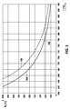
- FIG. 3 Internal resistance R I a Nernst cell, for example, the cell 134 of the sensor element 118 according to FIG. 1 , plotted for typical sensor elements 118 as a function of temperature T of a ceramic solid electrolyte 132.
- the curve 164 shows a new sensor element
- the curve 166 shows the behavior of an aged sensor element.
- a desired operating point of a new sensor element is in FIG. 2 denoted 168.
- the temperature of the sensor element should ideally be set, for example, to 780 ° C., which corresponds to an internal resistance of 220 ⁇ for a new sensor element. If this internal resistance R I is used as a controlled variable, the curve 166 of the aged sensor element, on the other hand, shows that in the aged sensor element this internal resistance of 220 ⁇ corresponds to a temperature of 820 ° C., ie a deviation of 40 ° C. This deviation is sensitive to sensor accuracy. To reach this temperature of 820 ° C, however, a considerably higher heating capacity is required.
- FIG. 2 Thus, for example, at the output of the comparator 156 and / or at the output of the actuator 150 would provide higher values than compared to the new sensor element.
- the one or more control elements 162 such a deviation can be detected, and it can optionally appropriate countermeasures are taken by correction in the control step and by influencing the manipulated variable accordingly.
- FIG. 4 For example, various possibilities of superimposing a control and a regulation, with simultaneous implementation of the method described above and taking account of an exhaust gas temperature T G as a control variable, are described. Plotted here on the vertical axis a size that characterizes the heating power of the heater 124 and which is here designated U H. This may, for example, be the heater voltage, although other parameters characterizing the heating power may also be applied.
- U H This may, for example, be the heater voltage, although other parameters characterizing the heating power may also be applied.
- a pilot control for example by means of the control device 148.
- the in FIG. 4 plotted characteristics show which heating power U H must be provided at the temperature of the gas in the measurement gas space 112 of the drive device 114 to the sensor element at a constant temperature, for example, the 780 ° C according to FIG. 3 , to keep.
- curve 170 shows a characteristic of a new sensor element
- curve 172 shows a characteristic of an aged sensor element.
- Such characteristic curves 170, 172 can be stored, for example, in the controller 160, so that, for example, the values D and E in FIG. 2 can be selected accordingly.
- the influencing of the at least one manipulated variable in the at least one control step can be on different, in FIG. 4 illustrated ways are done.
- an absolute cap 174 can be made to a fixed limit value of the heating power.
- dynamic limit values for example in the form of a lower limit value 176 and / or an upper limit value 178, which can be arranged, for example, around the characteristic curves 170, 172.
Claims (10)
- Procédé pour régler une température d'un élément de détection (118) pouvant être chauffé au moyen d'un dispositif de chauffage (124) et destiné à détecter au moins une propriété d'un gaz dans une chambre à gaz de mesure (112), notamment destiné à détecter une proportion d'au moins une composante gazeuse dans le gaz, le procédé comprenant au moins une régulation du dispositif de chauffage (124), la régulation comprenant les étapes suivantes :a) détection d'au moins une valeur réelle d'au moins une grandeur de régulation de l'élément de détection (118),b) détermination d'une valeur de consigne de l'au moins une grandeur de régulation ;c) génération d'au moins une grandeur de réglage du dispositif de chauffage (124) au moyen d'une comparaison de la valeur de consigne et de la valeur réelle,d) exécution d'au moins une étape de contrôle, au moins un paramètre utilisé pour le réglage de la température étant vérifié dans l'étape de contrôle et l'au moins une grandeur de réglage étant influencée en fonction de la vérification, le paramètre vérifié dans l'étape de contrôle étant l'au moins une grandeur de réglage,caractérisé en ce que l'influence est exercée de telle sorte que l'au moins une grandeur de réglage est limitée à une valeur sécurisée lorsque l'au moins une grandeur de réglage devient supérieure ou inférieure à une valeur limite pendant une durée donnée.
- Procédé selon la revendication précédente, au moins une grandeur de commande étant en outre détectée, la grandeur de commande caractérisant une influence d'un environnement de l'élément de détection (118) sur la température de l'élément de détection (118), notamment une grandeur de commande choisie parmi : une température ambiante de l'élément de détection (118) ; un paramètre de fonctionnement d'un dispositif contenant, générant ou utilisant le gaz, notamment une plage de fonctionnement d'un moteur à combustion interne, de préférence un point de fonctionnement de moteur ; un paramètre qui caractérise un courant de gaz qui se produit dans l'environnement de l'élément de détection (118) ; un paramètre qui caractérise, et notamment quantifie, une température qui se produit dans l'environnement de l'élément de détection, notamment une température des gaz d'échappement, une température de catalyseur et/ou une température de paroi de tube ; une vitesse de rotation de moteur ; un état de charge du moteur.
- Procédé selon l'une des revendications précédentes, le procédé comprenant en outre une commande du dispositif de chauffage (124), la régulation étant au moins temporairement superposée à la commande.
- Procédé selon la revendication 3, la commande du dispositif de chauffage (124) étant effectuée en tenant compte de la grandeur de commande.
- Procédé selon la revendication 3 ou 4, la détermination de la valeur de consigne et de préférence aussi la commande étant effectuées en tenant compte de la grandeur de commande.
- Procédé selon l'une des revendications précédentes, l'au moins une grandeur de régulation étant choisie parmi le groupe suivant : au moins une résistance interne de l'élément de détection (118), notamment une résistance interne d'au moins une cellule électrochimique (134) de l'élément de détection (118) ; une température de l'élément de détection (118) ; une tension entre au moins deux électrodes (126, 130) de l'élément de détection (118), notamment entre deux électrodes (126, 130) d'une cellule de Nernst (134) de l'élément de détection (118) ; un courant entre au moins deux électrodes (126, 130) de l'élément de détection (118), notamment entre au moins deux électrodes (126, 130) d'une cellule de pompage (134) de l'élément de détection (118) ; une résistance électrique d'une structure conductrice, notamment d'une structure conductrice de l'élément de détection (118).
- Procédé selon l'une des revendications précédentes, la grandeur de réglage étant choisie parmi le groupe suivant : une tension de chauffage appliquée au dispositif de chauffage (124) ; une puissance de chauffage appliquée au dispositif de chauffage (124) ; un courant de chauffage appliqué au dispositif de chauffage (124) ; un paramètre d'une modulation d'impulsions en largeur d'une puissance de chauffage appliquée au dispositif de chauffage (124).
- Procédé selon l'une des revendications précédentes, la vérification du paramètre dans l'étape de contrôle comprenant une ou plusieurs des vérifications suivantes :- une interrogation visant à vérifier si le paramètre atteint au moins une valeur de seuil fixe ou prédéfinie de manière dynamique, y devient inférieur ou y devient supérieur et, en option, pendant combien de temps c'est le cas ;- une interrogation visant à vérifier si une fluctuation dans le temps du paramètre au-delà d'une période de mesure devient inférieure à une fluctuation maximale prédéfinie, l'atteint ou y devient supérieure et, en option, pendant combien de temps c'est le cas ;- une comparaison d'une courbe dans le temps du paramètre avec au moins une courbe de consigne.
- Procédé selon l'une des revendications précédentes, l'influence de la grandeur de réglage dans l'étape de contrôle comprenant une ou plusieurs des influences suivantes :- un rejet d'une valeur individuelle ou de plusieurs valeurs du paramètre et une influence en résultant de la grandeur de réglage, notamment un rejet des valeurs mesurées du paramètre voisines dans le temps et fortement fluctuantes ;- un filtrage de la valeur réelle et une influence en résultant de la grandeur de réglage ;- un calcul de la moyenne de la valeur réelle et une influence en résultant de la grandeur de réglage ;- une limitation de la grandeur de réglage par une valeur minimale ou une valeur maximale fixe ou prédéfinie de manière dynamique ;- une fixation de la grandeur de réglage à une valeur par défaut ;- une réduction de la grandeur de réglage d'un montage prédéfini ou d'un facteur de correction ;- une conversion de la grandeur de réglage avec au moins une fonction de correction en une grandeur de réglage modifiée ;- une modification d'au moins un circuit de régulation (154) destiné à régler la température, notamment une déconnexion d'une part intégrale du circuit de régulation ;- une déconnexion de la régulation.
- Dispositif de détection (110) destiné à détecter au moins une propriété d'un gaz dans une chambre à gaz de mesure (112), notamment destiné à détecter une proportion d'une composante gazeuse, le dispositif de détection (110) comprenant au moins un élément de détection (118) destiné à détecter la propriété, le dispositif de détection (110) comprenant au moins un dispositif de chauffage (124) destiné à chauffer au moins une partie de l'élément de détection (118), le dispositif de détection (110) comprenant en outre au moins un dispositif de commande (114), caractérisé en ce que le dispositif de commande (114) est conçu pour mettre en oeuvre un procédé selon l'une des revendications précédentes.
Applications Claiming Priority (2)
| Application Number | Priority Date | Filing Date | Title |
|---|---|---|---|
| DE102010042013A DE102010042013A1 (de) | 2010-10-06 | 2010-10-06 | Verfahren zur Einstellung einer Temperatur eines Sensorelements |
| PCT/EP2011/066595 WO2012045599A1 (fr) | 2010-10-06 | 2011-09-23 | Procédé de réglage d'une température d'un élément capteur |
Publications (2)
| Publication Number | Publication Date |
|---|---|
| EP2625580A1 EP2625580A1 (fr) | 2013-08-14 |
| EP2625580B1 true EP2625580B1 (fr) | 2016-08-31 |
Family
ID=44720877
Family Applications (1)
| Application Number | Title | Priority Date | Filing Date |
|---|---|---|---|
| EP11763901.3A Active EP2625580B1 (fr) | 2010-10-06 | 2011-09-23 | Procédé de réglage d'une température d'un élément capteur |
Country Status (7)
| Country | Link |
|---|---|
| US (1) | US9625400B2 (fr) |
| EP (1) | EP2625580B1 (fr) |
| JP (1) | JP5950917B2 (fr) |
| CN (1) | CN103140819B (fr) |
| DE (1) | DE102010042013A1 (fr) |
| ES (1) | ES2605988T3 (fr) |
| WO (1) | WO2012045599A1 (fr) |
Cited By (1)
| Publication number | Priority date | Publication date | Assignee | Title |
|---|---|---|---|---|
| WO2023117237A1 (fr) * | 2021-12-22 | 2023-06-29 | Robert Bosch Gmbh | Procédé de chauffage d'un capteur de gaz d'échappement |
Families Citing this family (24)
| Publication number | Priority date | Publication date | Assignee | Title |
|---|---|---|---|---|
| DE102010042013A1 (de) * | 2010-10-06 | 2012-04-12 | Robert Bosch Gmbh | Verfahren zur Einstellung einer Temperatur eines Sensorelements |
| AU2012225337B2 (en) * | 2011-03-09 | 2016-04-28 | Signature Therapeutics, Inc. | Active agent prodrugs with heterocyclic linkers |
| DE102011007447A1 (de) * | 2011-04-15 | 2012-10-18 | Robert Bosch Gmbh | Verfahren zum Betrieb mindestens eines Sensorelements |
| KR20170082650A (ko) | 2012-03-28 | 2017-07-14 | 후지필름 가부시키가이샤 | 1-(2-디옥시-2-플루오로-4-티오-β-D-아라비노푸라노실)시토신의 염 |
| DE102012011252A1 (de) * | 2012-06-06 | 2013-12-12 | Man Truck & Bus Ag | Steuerung eines elektrischen Ansaugluftvorwärmers einer Brennkraftmaschine |
| JP6367568B2 (ja) * | 2014-02-07 | 2018-08-01 | 日本特殊陶業株式会社 | ガス検出装置 |
| DE102014208505B4 (de) * | 2014-05-07 | 2020-01-09 | Robert Bosch Gmbh | Verfahren zur sensorlosen Temperaturkompensation eines Sensors zur Lageerfassung |
| JP6410205B2 (ja) * | 2014-05-09 | 2018-10-24 | 株式会社デンソー | 制御システム |
| JP6255308B2 (ja) * | 2014-06-03 | 2017-12-27 | 日本特殊陶業株式会社 | ガスセンサ制御システム、ガスセンサ制御装置及びガスセンサの制御方法 |
| DE102015207880A1 (de) * | 2015-04-29 | 2016-11-03 | Robert Bosch Gmbh | Verfahren und Vorrichtung zur Bestimmung eines Innenwiderstandes eines Sensorelements |
| AT517215B1 (de) * | 2015-06-23 | 2016-12-15 | Avl List Gmbh | Verfahren zum Regeln einer Konditioniereinheit und Verbrauchsmesseinrichtung mit einer solchen Konditioniereinheit |
| FR3046873B1 (fr) * | 2016-01-19 | 2019-06-21 | Renault S.A.S | Procede et dispositif de protection d'une architecture electrique |
| DE102016207516B4 (de) * | 2016-05-02 | 2021-10-28 | Vitesco Technologies GmbH | Verfahren zur Alterungsbestimmung einer zur Ermittlung einer Gaskonzentration eines Gasgemischs ausgebildeten Sonde einer Brennkraftmaschine |
| CN107816733B (zh) * | 2016-09-14 | 2020-03-03 | 法雷奥热商业车辆德国有限公司 | 燃烧室的燃烧空气质量流保持恒定的方法及其加热装置 |
| DE102017201867B4 (de) * | 2017-02-07 | 2023-03-02 | Robert Bosch Gmbh | Vorrichtung und Verfahren zum Betrieb einer Heizung für eine Abgasreinigungsanlage |
| DE102017207802A1 (de) * | 2017-05-09 | 2018-11-15 | Robert Bosch Gmbh | Verfahren zum Betreiben eines Sensors zur Erfassung mindestens einer Eigenschaft eines Messgases in einem Messgasraum |
| JP6871080B2 (ja) * | 2017-06-16 | 2021-05-12 | 日本特殊陶業株式会社 | 制御状態設定装置およびセンサ制御システム |
| DE102017218355A1 (de) * | 2017-10-13 | 2019-04-18 | Rohde & Schwarz Gmbh & Co. Kg | Elektrisches messgerät und portables messsystem |
| JP2019085926A (ja) * | 2017-11-07 | 2019-06-06 | トヨタ自動車株式会社 | センサシステム |
| DE102017220114B3 (de) * | 2017-11-13 | 2019-05-16 | Robert Bosch Gmbh | Verfahren zum Betreiben einer Gassensorvorrichtung und Gassensorvorrichtung |
| FR3088121B1 (fr) * | 2018-11-06 | 2020-11-13 | Valeo Systemes Thermiques | Procede de detection de surchauffe pour dispositif de chauffage et unite de commande correspondante |
| CN110362130B (zh) * | 2019-08-21 | 2022-02-11 | 昂纳信息技术(深圳)有限公司 | 一种温度控制系统的驱动控制方法 |
| KR102501286B1 (ko) * | 2020-12-15 | 2023-02-22 | 한국전자통신연구원 | 기체 센서의 이상 감지 장치 및 방법 |
| DE102021213465A1 (de) * | 2021-11-30 | 2023-06-01 | Robert Bosch Gesellschaft mit beschränkter Haftung | Verfahren zum Betreiben eines Sensors zum Bestimmen mindestens eines Anteils eines Gases in einem Messgasraum |
Citations (1)
| Publication number | Priority date | Publication date | Assignee | Title |
|---|---|---|---|---|
| US5974857A (en) * | 1996-07-10 | 1999-11-02 | Denso Corporation | Apparatus and method for controlling oxygen sensor heating |
Family Cites Families (32)
| Publication number | Priority date | Publication date | Assignee | Title |
|---|---|---|---|---|
| JPS5545224A (en) | 1978-09-26 | 1980-03-29 | Sony Corp | Filter circuit |
| JPH0738844Y2 (ja) * | 1988-10-07 | 1995-09-06 | トヨタ自動車株式会社 | 酸素センサ用ヒータ制御装置 |
| JPH02285245A (ja) | 1989-04-26 | 1990-11-22 | Toyota Motor Corp | 酸素センサ用ヒータの制御装置 |
| JPH0319957A (ja) | 1989-05-17 | 1991-01-29 | Seiko Epson Corp | 電動毛玉取器 |
| US5287281A (en) * | 1991-02-27 | 1994-02-15 | Echlin Inc. | Computer controlled flow of nitrous oxide injected into an internal combustion engine |
| JPH1026599A (ja) | 1996-07-10 | 1998-01-27 | Denso Corp | 酸素濃度検出装置 |
| JPH1088227A (ja) | 1996-09-19 | 1998-04-07 | Olympus Optical Co Ltd | 金属材料の焼戻し方法及び接続用端子ピン |
| JP3163994B2 (ja) * | 1996-10-07 | 2001-05-08 | トヨタ自動車株式会社 | 内燃機関関係機器の異常検出装置およびこれを備える動力出力装置 |
| JP3891234B2 (ja) * | 1997-10-02 | 2007-03-14 | 株式会社デンソー | 内燃機関の空燃比センサ系異常診断装置 |
| JP2001330580A (ja) | 2000-05-19 | 2001-11-30 | Unisia Jecs Corp | 酸素濃度検出装置のヒータ診断装置 |
| JP2005002974A (ja) | 2003-06-16 | 2005-01-06 | Toyota Motor Corp | 排気ガスセンサのヒータ制御装置 |
| JP3855979B2 (ja) * | 2003-08-04 | 2006-12-13 | トヨタ自動車株式会社 | 内燃機関の排気ガスセンサの制御装置 |
| JP2005195368A (ja) | 2003-12-26 | 2005-07-21 | Hitachi Ltd | 酸素濃度検出制御装置 |
| JP2006153601A (ja) | 2004-11-29 | 2006-06-15 | Honda Motor Co Ltd | ガスセンサの故障検出装置およびガスセンサの故障検出方法 |
| US20070119435A1 (en) * | 2005-11-30 | 2007-05-31 | Advanced Injection Technologies, Inc. | Engine monitoring and performance control system |
| JP4321520B2 (ja) * | 2005-12-28 | 2009-08-26 | トヨタ自動車株式会社 | 動力出力装置およびこれを搭載する車両並びに動力出力装置の制御方法 |
| JP2007248113A (ja) * | 2006-03-14 | 2007-09-27 | Denso Corp | ガス濃度検出装置 |
| JP4501877B2 (ja) * | 2006-03-14 | 2010-07-14 | 株式会社デンソー | 内燃機関の制御装置 |
| JP4697052B2 (ja) * | 2006-05-26 | 2011-06-08 | 株式会社デンソー | ガス濃度検出装置 |
| US20070282558A1 (en) * | 2006-06-01 | 2007-12-06 | Denso Corporation | Abnormal condition determining system for steering angle sensor |
| DE102006053808B4 (de) | 2006-11-15 | 2021-01-07 | Robert Bosch Gmbh | Verfahren zur Bestimmung der Temperatur eines Messfühlers |
| DE102007001562A1 (de) | 2007-01-10 | 2008-07-17 | Robert Bosch Gmbh | Sensorelement für einen Gassensor zur Bestimmung einer physikalischen Eigenschaft eines Messgases |
| JP4826566B2 (ja) | 2007-09-20 | 2011-11-30 | トヨタ自動車株式会社 | 排気ガスセンサの素子温度制御装置 |
| JP4609545B2 (ja) * | 2008-08-06 | 2011-01-12 | 株式会社デンソー | ガスセンサの信号処理装置 |
| DE102008055108A1 (de) | 2008-12-22 | 2010-07-01 | Robert Bosch Gmbh | Sensoranordnung mit Temperaturfühler |
| WO2010093037A1 (fr) | 2009-02-16 | 2010-08-19 | 日本電気株式会社 | Dispositif, système et procédé de passerelle |
| DE102009001242A1 (de) | 2009-02-27 | 2010-09-02 | Robert Bosch Gmbh | Festelektrolytgassensor für die Messung diverser Gasspezies (II) |
| DE102009001839A1 (de) | 2009-03-25 | 2010-09-30 | Robert Bosch Gmbh | Verfahren zum Betreiben eines Sensorelements und Sensorelement |
| DE102009047648B4 (de) * | 2009-12-08 | 2022-03-03 | Robert Bosch Gmbh | Verfahren und Vorrichtung zur Diagnose von Abweichungen bei einer Einzelzylinder-Lambdaregelung |
| DE102010042013A1 (de) * | 2010-10-06 | 2012-04-12 | Robert Bosch Gmbh | Verfahren zur Einstellung einer Temperatur eines Sensorelements |
| US8140246B1 (en) * | 2010-10-25 | 2012-03-20 | Toyota Motor Engineering & Manufacturing North America, Inc. | Method and system for detecting a presence of a block heater in an automobile |
| US9714913B2 (en) * | 2012-02-14 | 2017-07-25 | Toyota Jidosha Kabushiki Kaisha | Control device for exhaust gas sensor |
-
2010
- 2010-10-06 DE DE102010042013A patent/DE102010042013A1/de active Pending
-
2011
- 2011-09-23 CN CN201180048510.0A patent/CN103140819B/zh active Active
- 2011-09-23 JP JP2013532114A patent/JP5950917B2/ja active Active
- 2011-09-23 EP EP11763901.3A patent/EP2625580B1/fr active Active
- 2011-09-23 ES ES11763901.3T patent/ES2605988T3/es active Active
- 2011-09-23 US US13/877,448 patent/US9625400B2/en active Active
- 2011-09-23 WO PCT/EP2011/066595 patent/WO2012045599A1/fr active Application Filing
Patent Citations (1)
| Publication number | Priority date | Publication date | Assignee | Title |
|---|---|---|---|---|
| US5974857A (en) * | 1996-07-10 | 1999-11-02 | Denso Corporation | Apparatus and method for controlling oxygen sensor heating |
Cited By (1)
| Publication number | Priority date | Publication date | Assignee | Title |
|---|---|---|---|---|
| WO2023117237A1 (fr) * | 2021-12-22 | 2023-06-29 | Robert Bosch Gmbh | Procédé de chauffage d'un capteur de gaz d'échappement |
Also Published As
| Publication number | Publication date |
|---|---|
| JP2013539043A (ja) | 2013-10-17 |
| DE102010042013A1 (de) | 2012-04-12 |
| JP5950917B2 (ja) | 2016-07-13 |
| US9625400B2 (en) | 2017-04-18 |
| ES2605988T3 (es) | 2017-03-17 |
| CN103140819A (zh) | 2013-06-05 |
| EP2625580A1 (fr) | 2013-08-14 |
| CN103140819B (zh) | 2016-11-16 |
| US20130327124A1 (en) | 2013-12-12 |
| WO2012045599A1 (fr) | 2012-04-12 |
Similar Documents
| Publication | Publication Date | Title |
|---|---|---|
| EP2625580B1 (fr) | Procédé de réglage d'une température d'un élément capteur | |
| DE102009047648B4 (de) | Verfahren und Vorrichtung zur Diagnose von Abweichungen bei einer Einzelzylinder-Lambdaregelung | |
| DE102008005110B4 (de) | Verfahren und Steuerung zum Betreiben und Einstellen einer Lambda-Sonde | |
| DE10163007A1 (de) | Heizeinrichtungssteuervorrichtung für einen Gaskonzentrationssensor | |
| EP2271920B1 (fr) | Circuit de commande pour capteur de gaz électrochimique et procédé de réglage d'un tel capteur de gaz électrochimique | |
| EP4045902B1 (fr) | Procede destine au fonctionnement d'une sonde lambda à large bande | |
| DE19625899C2 (de) | Verfahren zum Betreiben einer Sauerstoffsonde | |
| WO2013113757A1 (fr) | Procédé de commande et de diagnostic d'un élément capteur pour la détection d'au moins une caractéristiques d'un gaz dans une chambre de gaz à mesurer | |
| DE102008011833B4 (de) | Verfahren zum Steuern einer lambdageregelten Abgasanlage einer Brennkraftmaschine | |
| EP3084191B1 (fr) | Procédé de commande de l'étage de sortie d'un consommateur électrique de véhicule à moteur | |
| EP2652297A1 (fr) | Procédé de détection de la capacité à fonctionner d'une sonde lambda à saut de tension | |
| WO2012034761A1 (fr) | Procédé de détermination d'une propriété d'un gaz dans une chambre de gaz de mesure | |
| WO2012097897A1 (fr) | Procédé et dispositif de détection d'au moins un paramètre d'un gaz | |
| EP3155251B1 (fr) | Procédé permettant d'évaluer l'écart d'une courbe caractéristique | |
| DE102022211060A1 (de) | Verfahren zum Betreiben eines Sensors zur Erfassung mindestens einer Eigenschaft eines Messgases in einem Messgasraum | |
| DE102012216791A1 (de) | Verfahren zum Betrieb eines Sensorelements zur Erfassung mindestens eines Anteils eines Gases in einem Messgasraum | |
| DE102012216803A1 (de) | Verfahren zum Betrieb eines Sensorelements zur Erfassung mindestens eines Anteils eines Gases in einem Messgasraum | |
| DE102010041421A1 (de) | Verfahren zum Betrieb eines Sensorelements | |
| DE102012211685A1 (de) | Verfahren und Vorrichtung zur Bestimmung einer Luftzahl Lambda mit einem Gas-Sensor | |
| DE102011078056A1 (de) | Verfahren zum Abgleich einer Kennlinie eines Sensorelements | |
| WO2023099253A1 (fr) | Procédé d'activation d'un capteur permettant de déterminer au moins une proportion d'un gaz dans une chambre de gaz de mesure | |
| DE102011089359A1 (de) | Verfahren zum Betreiben eines Gassensors | |
| DE102009028288A1 (de) | Verfahren zum Betreiben der Heizung einer Abgassonde | |
| DE102012013781A1 (de) | Verfahren und Vorrichtung zur Qualifizierung eines Sensormesssignals |
Legal Events
| Date | Code | Title | Description |
|---|---|---|---|
| PUAI | Public reference made under article 153(3) epc to a published international application that has entered the european phase |
Free format text: ORIGINAL CODE: 0009012 |
|
| 17P | Request for examination filed |
Effective date: 20130506 |
|
| AK | Designated contracting states |
Kind code of ref document: A1 Designated state(s): AL AT BE BG CH CY CZ DE DK EE ES FI FR GB GR HR HU IE IS IT LI LT LU LV MC MK MT NL NO PL PT RO RS SE SI SK SM TR |
|
| DAX | Request for extension of the european patent (deleted) | ||
| TPAC | Observations filed by third parties |
Free format text: ORIGINAL CODE: EPIDOSNTIPA |
|
| 17Q | First examination report despatched |
Effective date: 20150904 |
|
| GRAP | Despatch of communication of intention to grant a patent |
Free format text: ORIGINAL CODE: EPIDOSNIGR1 |
|
| INTG | Intention to grant announced |
Effective date: 20160525 |
|
| GRAS | Grant fee paid |
Free format text: ORIGINAL CODE: EPIDOSNIGR3 |
|
| GRAA | (expected) grant |
Free format text: ORIGINAL CODE: 0009210 |
|
| AK | Designated contracting states |
Kind code of ref document: B1 Designated state(s): AL AT BE BG CH CY CZ DE DK EE ES FI FR GB GR HR HU IE IS IT LI LT LU LV MC MK MT NL NO PL PT RO RS SE SI SK SM TR |
|
| REG | Reference to a national code |
Ref country code: CH Ref legal event code: EP Ref country code: GB Ref legal event code: FG4D Free format text: NOT ENGLISH |
|
| REG | Reference to a national code |
Ref country code: IE Ref legal event code: FG4D Free format text: LANGUAGE OF EP DOCUMENT: GERMAN |
|
| REG | Reference to a national code |
Ref country code: DE Ref legal event code: R096 Ref document number: 502011010588 Country of ref document: DE |
|
| REG | Reference to a national code |
Ref country code: AT Ref legal event code: REF Ref document number: 825505 Country of ref document: AT Kind code of ref document: T Effective date: 20161015 |
|
| REG | Reference to a national code |
Ref country code: FR Ref legal event code: PLFP Year of fee payment: 6 |
|
| REG | Reference to a national code |
Ref country code: LT Ref legal event code: MG4D |
|
| REG | Reference to a national code |
Ref country code: NL Ref legal event code: MP Effective date: 20160831 |
|
| PG25 | Lapsed in a contracting state [announced via postgrant information from national office to epo] |
Ref country code: RS Free format text: LAPSE BECAUSE OF FAILURE TO SUBMIT A TRANSLATION OF THE DESCRIPTION OR TO PAY THE FEE WITHIN THE PRESCRIBED TIME-LIMIT Effective date: 20160831 Ref country code: HR Free format text: LAPSE BECAUSE OF FAILURE TO SUBMIT A TRANSLATION OF THE DESCRIPTION OR TO PAY THE FEE WITHIN THE PRESCRIBED TIME-LIMIT Effective date: 20160831 Ref country code: NO Free format text: LAPSE BECAUSE OF FAILURE TO SUBMIT A TRANSLATION OF THE DESCRIPTION OR TO PAY THE FEE WITHIN THE PRESCRIBED TIME-LIMIT Effective date: 20161130 Ref country code: FI Free format text: LAPSE BECAUSE OF FAILURE TO SUBMIT A TRANSLATION OF THE DESCRIPTION OR TO PAY THE FEE WITHIN THE PRESCRIBED TIME-LIMIT Effective date: 20160831 Ref country code: LT Free format text: LAPSE BECAUSE OF FAILURE TO SUBMIT A TRANSLATION OF THE DESCRIPTION OR TO PAY THE FEE WITHIN THE PRESCRIBED TIME-LIMIT Effective date: 20160831 |
|
| PG25 | Lapsed in a contracting state [announced via postgrant information from national office to epo] |
Ref country code: LV Free format text: LAPSE BECAUSE OF FAILURE TO SUBMIT A TRANSLATION OF THE DESCRIPTION OR TO PAY THE FEE WITHIN THE PRESCRIBED TIME-LIMIT Effective date: 20160831 Ref country code: GR Free format text: LAPSE BECAUSE OF FAILURE TO SUBMIT A TRANSLATION OF THE DESCRIPTION OR TO PAY THE FEE WITHIN THE PRESCRIBED TIME-LIMIT Effective date: 20161201 Ref country code: NL Free format text: LAPSE BECAUSE OF FAILURE TO SUBMIT A TRANSLATION OF THE DESCRIPTION OR TO PAY THE FEE WITHIN THE PRESCRIBED TIME-LIMIT Effective date: 20160831 Ref country code: SE Free format text: LAPSE BECAUSE OF FAILURE TO SUBMIT A TRANSLATION OF THE DESCRIPTION OR TO PAY THE FEE WITHIN THE PRESCRIBED TIME-LIMIT Effective date: 20160831 Ref country code: BE Free format text: LAPSE BECAUSE OF NON-PAYMENT OF DUE FEES Effective date: 20160930 |
|
| REG | Reference to a national code |
Ref country code: ES Ref legal event code: FG2A Ref document number: 2605988 Country of ref document: ES Kind code of ref document: T3 Effective date: 20170317 |
|
| PG25 | Lapsed in a contracting state [announced via postgrant information from national office to epo] |
Ref country code: EE Free format text: LAPSE BECAUSE OF FAILURE TO SUBMIT A TRANSLATION OF THE DESCRIPTION OR TO PAY THE FEE WITHIN THE PRESCRIBED TIME-LIMIT Effective date: 20160831 Ref country code: RO Free format text: LAPSE BECAUSE OF FAILURE TO SUBMIT A TRANSLATION OF THE DESCRIPTION OR TO PAY THE FEE WITHIN THE PRESCRIBED TIME-LIMIT Effective date: 20160831 |
|
| REG | Reference to a national code |
Ref country code: CH Ref legal event code: PL |
|
| PG25 | Lapsed in a contracting state [announced via postgrant information from national office to epo] |
Ref country code: DK Free format text: LAPSE BECAUSE OF FAILURE TO SUBMIT A TRANSLATION OF THE DESCRIPTION OR TO PAY THE FEE WITHIN THE PRESCRIBED TIME-LIMIT Effective date: 20160831 Ref country code: PL Free format text: LAPSE BECAUSE OF FAILURE TO SUBMIT A TRANSLATION OF THE DESCRIPTION OR TO PAY THE FEE WITHIN THE PRESCRIBED TIME-LIMIT Effective date: 20160831 Ref country code: BG Free format text: LAPSE BECAUSE OF FAILURE TO SUBMIT A TRANSLATION OF THE DESCRIPTION OR TO PAY THE FEE WITHIN THE PRESCRIBED TIME-LIMIT Effective date: 20161130 Ref country code: SM Free format text: LAPSE BECAUSE OF FAILURE TO SUBMIT A TRANSLATION OF THE DESCRIPTION OR TO PAY THE FEE WITHIN THE PRESCRIBED TIME-LIMIT Effective date: 20160831 Ref country code: SK Free format text: LAPSE BECAUSE OF FAILURE TO SUBMIT A TRANSLATION OF THE DESCRIPTION OR TO PAY THE FEE WITHIN THE PRESCRIBED TIME-LIMIT Effective date: 20160831 Ref country code: PT Free format text: LAPSE BECAUSE OF FAILURE TO SUBMIT A TRANSLATION OF THE DESCRIPTION OR TO PAY THE FEE WITHIN THE PRESCRIBED TIME-LIMIT Effective date: 20170102 Ref country code: CZ Free format text: LAPSE BECAUSE OF FAILURE TO SUBMIT A TRANSLATION OF THE DESCRIPTION OR TO PAY THE FEE WITHIN THE PRESCRIBED TIME-LIMIT Effective date: 20160831 |
|
| REG | Reference to a national code |
Ref country code: DE Ref legal event code: R097 Ref document number: 502011010588 Country of ref document: DE |
|
| REG | Reference to a national code |
Ref country code: IE Ref legal event code: MM4A |
|
| PLBE | No opposition filed within time limit |
Free format text: ORIGINAL CODE: 0009261 |
|
| STAA | Information on the status of an ep patent application or granted ep patent |
Free format text: STATUS: NO OPPOSITION FILED WITHIN TIME LIMIT |
|
| PG25 | Lapsed in a contracting state [announced via postgrant information from national office to epo] |
Ref country code: IE Free format text: LAPSE BECAUSE OF NON-PAYMENT OF DUE FEES Effective date: 20160923 Ref country code: LI Free format text: LAPSE BECAUSE OF NON-PAYMENT OF DUE FEES Effective date: 20160930 Ref country code: CH Free format text: LAPSE BECAUSE OF NON-PAYMENT OF DUE FEES Effective date: 20160930 |
|
| 26N | No opposition filed |
Effective date: 20170601 |
|
| PG25 | Lapsed in a contracting state [announced via postgrant information from national office to epo] |
Ref country code: SI Free format text: LAPSE BECAUSE OF FAILURE TO SUBMIT A TRANSLATION OF THE DESCRIPTION OR TO PAY THE FEE WITHIN THE PRESCRIBED TIME-LIMIT Effective date: 20160831 Ref country code: LU Free format text: LAPSE BECAUSE OF NON-PAYMENT OF DUE FEES Effective date: 20160923 |
|
| REG | Reference to a national code |
Ref country code: FR Ref legal event code: PLFP Year of fee payment: 7 |
|
| REG | Reference to a national code |
Ref country code: AT Ref legal event code: MM01 Ref document number: 825505 Country of ref document: AT Kind code of ref document: T Effective date: 20160923 |
|
| REG | Reference to a national code |
Ref country code: BE Ref legal event code: MM Effective date: 20160930 |
|
| PG25 | Lapsed in a contracting state [announced via postgrant information from national office to epo] |
Ref country code: AT Free format text: LAPSE BECAUSE OF NON-PAYMENT OF DUE FEES Effective date: 20160923 |
|
| PG25 | Lapsed in a contracting state [announced via postgrant information from national office to epo] |
Ref country code: HU Free format text: LAPSE BECAUSE OF FAILURE TO SUBMIT A TRANSLATION OF THE DESCRIPTION OR TO PAY THE FEE WITHIN THE PRESCRIBED TIME-LIMIT; INVALID AB INITIO Effective date: 20110923 Ref country code: CY Free format text: LAPSE BECAUSE OF FAILURE TO SUBMIT A TRANSLATION OF THE DESCRIPTION OR TO PAY THE FEE WITHIN THE PRESCRIBED TIME-LIMIT Effective date: 20160831 |
|
| PG25 | Lapsed in a contracting state [announced via postgrant information from national office to epo] |
Ref country code: TR Free format text: LAPSE BECAUSE OF FAILURE TO SUBMIT A TRANSLATION OF THE DESCRIPTION OR TO PAY THE FEE WITHIN THE PRESCRIBED TIME-LIMIT Effective date: 20160831 Ref country code: MT Free format text: LAPSE BECAUSE OF FAILURE TO SUBMIT A TRANSLATION OF THE DESCRIPTION OR TO PAY THE FEE WITHIN THE PRESCRIBED TIME-LIMIT Effective date: 20160831 Ref country code: MK Free format text: LAPSE BECAUSE OF FAILURE TO SUBMIT A TRANSLATION OF THE DESCRIPTION OR TO PAY THE FEE WITHIN THE PRESCRIBED TIME-LIMIT Effective date: 20160831 Ref country code: IS Free format text: LAPSE BECAUSE OF FAILURE TO SUBMIT A TRANSLATION OF THE DESCRIPTION OR TO PAY THE FEE WITHIN THE PRESCRIBED TIME-LIMIT Effective date: 20160831 Ref country code: MC Free format text: LAPSE BECAUSE OF FAILURE TO SUBMIT A TRANSLATION OF THE DESCRIPTION OR TO PAY THE FEE WITHIN THE PRESCRIBED TIME-LIMIT Effective date: 20160831 |
|
| REG | Reference to a national code |
Ref country code: FR Ref legal event code: PLFP Year of fee payment: 8 |
|
| PG25 | Lapsed in a contracting state [announced via postgrant information from national office to epo] |
Ref country code: AL Free format text: LAPSE BECAUSE OF FAILURE TO SUBMIT A TRANSLATION OF THE DESCRIPTION OR TO PAY THE FEE WITHIN THE PRESCRIBED TIME-LIMIT Effective date: 20160831 |
|
| PGFP | Annual fee paid to national office [announced via postgrant information from national office to epo] |
Ref country code: GB Payment date: 20230921 Year of fee payment: 13 |
|
| PGFP | Annual fee paid to national office [announced via postgrant information from national office to epo] |
Ref country code: FR Payment date: 20230918 Year of fee payment: 13 |
|
| PGFP | Annual fee paid to national office [announced via postgrant information from national office to epo] |
Ref country code: ES Payment date: 20231019 Year of fee payment: 13 |
|
| PGFP | Annual fee paid to national office [announced via postgrant information from national office to epo] |
Ref country code: IT Payment date: 20230929 Year of fee payment: 13 Ref country code: DE Payment date: 20231124 Year of fee payment: 13 |