EP2625580B1 - Method for adjusting a temperature of a sensor element - Google Patents
Method for adjusting a temperature of a sensor element Download PDFInfo
- Publication number
- EP2625580B1 EP2625580B1 EP11763901.3A EP11763901A EP2625580B1 EP 2625580 B1 EP2625580 B1 EP 2625580B1 EP 11763901 A EP11763901 A EP 11763901A EP 2625580 B1 EP2625580 B1 EP 2625580B1
- Authority
- EP
- European Patent Office
- Prior art keywords
- sensor element
- temperature
- control
- manipulated variable
- variable
- Prior art date
- Legal status (The legal status is an assumption and is not a legal conclusion. Google has not performed a legal analysis and makes no representation as to the accuracy of the status listed.)
- Active
Links
- 238000000034 method Methods 0.000 title claims description 55
- 238000010438 heat treatment Methods 0.000 claims description 85
- 238000012937 correction Methods 0.000 claims description 15
- 238000001914 filtration Methods 0.000 claims description 5
- 238000005086 pumping Methods 0.000 claims description 5
- 238000002485 combustion reaction Methods 0.000 claims description 4
- 239000003054 catalyst Substances 0.000 claims description 3
- 230000009467 reduction Effects 0.000 claims description 3
- 238000012935 Averaging Methods 0.000 claims description 2
- 238000006243 chemical reaction Methods 0.000 claims description 2
- 238000012544 monitoring process Methods 0.000 claims 5
- 230000003213 activating effect Effects 0.000 claims 2
- 238000012986 modification Methods 0.000 claims 1
- 230000004048 modification Effects 0.000 claims 1
- 239000007789 gas Substances 0.000 description 73
- 239000000523 sample Substances 0.000 description 21
- 238000005259 measurement Methods 0.000 description 15
- 238000013021 overheating Methods 0.000 description 11
- 230000006870 function Effects 0.000 description 10
- 239000007784 solid electrolyte Substances 0.000 description 10
- 238000001514 detection method Methods 0.000 description 8
- 230000002123 temporal effect Effects 0.000 description 7
- MCMNRKCIXSYSNV-UHFFFAOYSA-N ZrO2 Inorganic materials O=[Zr]=O MCMNRKCIXSYSNV-UHFFFAOYSA-N 0.000 description 6
- MWUXSHHQAYIFBG-UHFFFAOYSA-N nitrogen oxide Inorganic materials O=[N] MWUXSHHQAYIFBG-UHFFFAOYSA-N 0.000 description 6
- 230000033228 biological regulation Effects 0.000 description 5
- 239000000919 ceramic Substances 0.000 description 5
- 230000006378 damage Effects 0.000 description 5
- 230000001419 dependent effect Effects 0.000 description 5
- 239000001301 oxygen Substances 0.000 description 4
- 229910052760 oxygen Inorganic materials 0.000 description 4
- RVTZCBVAJQQJTK-UHFFFAOYSA-N oxygen(2-);zirconium(4+) Chemical compound [O-2].[O-2].[Zr+4] RVTZCBVAJQQJTK-UHFFFAOYSA-N 0.000 description 4
- QVGXLLKOCUKJST-UHFFFAOYSA-N atomic oxygen Chemical compound [O] QVGXLLKOCUKJST-UHFFFAOYSA-N 0.000 description 3
- IJGRMHOSHXDMSA-UHFFFAOYSA-N Atomic nitrogen Chemical compound N#N IJGRMHOSHXDMSA-UHFFFAOYSA-N 0.000 description 2
- 230000008901 benefit Effects 0.000 description 2
- 238000001816 cooling Methods 0.000 description 2
- 230000003111 delayed effect Effects 0.000 description 2
- 229930195733 hydrocarbon Natural products 0.000 description 2
- 150000002430 hydrocarbons Chemical class 0.000 description 2
- 230000006872 improvement Effects 0.000 description 2
- BASFCYQUMIYNBI-UHFFFAOYSA-N platinum Chemical compound [Pt] BASFCYQUMIYNBI-UHFFFAOYSA-N 0.000 description 2
- 238000012545 processing Methods 0.000 description 2
- 230000001105 regulatory effect Effects 0.000 description 2
- 239000007787 solid Substances 0.000 description 2
- 230000004913 activation Effects 0.000 description 1
- 230000032683 aging Effects 0.000 description 1
- 230000003321 amplification Effects 0.000 description 1
- 238000009529 body temperature measurement Methods 0.000 description 1
- 230000008859 change Effects 0.000 description 1
- 230000003750 conditioning effect Effects 0.000 description 1
- 230000001276 controlling effect Effects 0.000 description 1
- 238000005314 correlation function Methods 0.000 description 1
- 230000007797 corrosion Effects 0.000 description 1
- 238000005260 corrosion Methods 0.000 description 1
- 230000002950 deficient Effects 0.000 description 1
- 238000010586 diagram Methods 0.000 description 1
- 230000000694 effects Effects 0.000 description 1
- 229910052751 metal Inorganic materials 0.000 description 1
- 239000002184 metal Substances 0.000 description 1
- 229910052757 nitrogen Inorganic materials 0.000 description 1
- 238000003199 nucleic acid amplification method Methods 0.000 description 1
- -1 oxygen ions Chemical class 0.000 description 1
- 229910052697 platinum Inorganic materials 0.000 description 1
- 230000004044 response Effects 0.000 description 1
- 238000004088 simulation Methods 0.000 description 1
- 230000006641 stabilisation Effects 0.000 description 1
- 238000011105 stabilization Methods 0.000 description 1
- 239000000126 substance Substances 0.000 description 1
- 238000012360 testing method Methods 0.000 description 1
- 238000011144 upstream manufacturing Methods 0.000 description 1
Images


Classifications
-
- G—PHYSICS
- G01—MEASURING; TESTING
- G01N—INVESTIGATING OR ANALYSING MATERIALS BY DETERMINING THEIR CHEMICAL OR PHYSICAL PROPERTIES
- G01N25/00—Investigating or analyzing materials by the use of thermal means
- G01N25/18—Investigating or analyzing materials by the use of thermal means by investigating thermal conductivity
-
- F—MECHANICAL ENGINEERING; LIGHTING; HEATING; WEAPONS; BLASTING
- F01—MACHINES OR ENGINES IN GENERAL; ENGINE PLANTS IN GENERAL; STEAM ENGINES
- F01N—GAS-FLOW SILENCERS OR EXHAUST APPARATUS FOR MACHINES OR ENGINES IN GENERAL; GAS-FLOW SILENCERS OR EXHAUST APPARATUS FOR INTERNAL COMBUSTION ENGINES
- F01N11/00—Monitoring or diagnostic devices for exhaust-gas treatment apparatus, e.g. for catalytic activity
- F01N11/007—Monitoring or diagnostic devices for exhaust-gas treatment apparatus, e.g. for catalytic activity the diagnostic devices measuring oxygen or air concentration downstream of the exhaust apparatus
-
- G—PHYSICS
- G01—MEASURING; TESTING
- G01N—INVESTIGATING OR ANALYSING MATERIALS BY DETERMINING THEIR CHEMICAL OR PHYSICAL PROPERTIES
- G01N27/00—Investigating or analysing materials by the use of electric, electrochemical, or magnetic means
- G01N27/26—Investigating or analysing materials by the use of electric, electrochemical, or magnetic means by investigating electrochemical variables; by using electrolysis or electrophoresis
- G01N27/403—Cells and electrode assemblies
- G01N27/406—Cells and probes with solid electrolytes
- G01N27/4067—Means for heating or controlling the temperature of the solid electrolyte
-
- G—PHYSICS
- G05—CONTROLLING; REGULATING
- G05D—SYSTEMS FOR CONTROLLING OR REGULATING NON-ELECTRIC VARIABLES
- G05D23/00—Control of temperature
- G05D23/19—Control of temperature characterised by the use of electric means
- G05D23/20—Control of temperature characterised by the use of electric means with sensing elements having variation of electric or magnetic properties with change of temperature
- G05D23/24—Control of temperature characterised by the use of electric means with sensing elements having variation of electric or magnetic properties with change of temperature the sensing element having a resistance varying with temperature, e.g. a thermistor
-
- F—MECHANICAL ENGINEERING; LIGHTING; HEATING; WEAPONS; BLASTING
- F01—MACHINES OR ENGINES IN GENERAL; ENGINE PLANTS IN GENERAL; STEAM ENGINES
- F01N—GAS-FLOW SILENCERS OR EXHAUST APPARATUS FOR MACHINES OR ENGINES IN GENERAL; GAS-FLOW SILENCERS OR EXHAUST APPARATUS FOR INTERNAL COMBUSTION ENGINES
- F01N2560/00—Exhaust systems with means for detecting or measuring exhaust gas components or characteristics
- F01N2560/20—Sensor having heating means
-
- Y—GENERAL TAGGING OF NEW TECHNOLOGICAL DEVELOPMENTS; GENERAL TAGGING OF CROSS-SECTIONAL TECHNOLOGIES SPANNING OVER SEVERAL SECTIONS OF THE IPC; TECHNICAL SUBJECTS COVERED BY FORMER USPC CROSS-REFERENCE ART COLLECTIONS [XRACs] AND DIGESTS
- Y02—TECHNOLOGIES OR APPLICATIONS FOR MITIGATION OR ADAPTATION AGAINST CLIMATE CHANGE
- Y02T—CLIMATE CHANGE MITIGATION TECHNOLOGIES RELATED TO TRANSPORTATION
- Y02T10/00—Road transport of goods or passengers
- Y02T10/10—Internal combustion engine [ICE] based vehicles
- Y02T10/40—Engine management systems
Definitions
- a plurality of sensor elements for detecting at least one property of a gas in a sample gas space is known.
- this can be any property of the gas, for example a physical and / or chemical property of the gas.
- the invention will be described below with reference to sensor elements for detecting a proportion, ie for example a partial pressure and / or a percentage, of at least one gas component in the gas.
- the gas component may in particular be oxygen.
- other gas components can alternatively or additionally be detected, for example nitrogen oxides, hydrocarbons or other gas components.
- the invention is not limited to the detection of gas components, but in principle, alternatively or additionally, other properties of the gas can be detected.
- sensor elements are used, which are based on the use of at least one solid electrolyte, ie an ion-conducting solid, for example, an oxygen-ion-conducting solid.
- solid electrolytes can be prepared, for example, based on zirconium dioxide, for example yttrium-stabilized zirconium dioxide and / or scandium-doped zirconium dioxide.
- sensor elements are used for example in the automotive field to detect gas components in the exhaust gas of an internal combustion engine with at least one engine. Examples of such sensor elements are in Robert Bosch GmbH: Sensors in the motor vehicle, issue 2007, pages 154-159 described.
- the sensor elements shown there can in principle also be operated by a method according to the present invention and / or used within the scope of a sensor device according to the invention.
- a lambda probe is generally based on the use of at least one galvanic oxygen concentration cell with at least one solid electrolyte.
- so-called pump cells can also be used.
- Lambda probes may have a unicellular or else a multicellular structure, wherein reference may likewise be made by way of example to the cited prior art.
- such sensor elements have at least one heating device.
- the solid electrolyte typically becomes conductive at an activation temperature of about 350 ° C for oxygen ions.
- the nominal temperature of conventional lambda probes is generally much higher, for example at 650 ° C-850 ° C. In order to achieve the nominal temperature regardless of the ambient conditions, for example the temperature of the exhaust gas, the sensor element is usually actively electrically heated.
- the sensor elements of the type mentioned have at least one electrical heating element, which is also generally referred to below as a heating device and which is usually controlled by at least one control unit.
- a heating device which is usually controlled by at least one control unit.
- known zirconia-based lambda probes have an integrated platinum heater which is typically designed to have a larger heat capacity reserve under normal operating conditions.
- the required for the operation of the sensor element heater voltage or heating power is usually much smaller than the available supply voltage or power supply.
- operating temperatures of 780 ° C are already achieved with heater voltages of less than 8 V in typical sensor elements of the type mentioned above.
- the sensor element is not operated with a DC voltage but with a clocked RMS voltage, which is generated by pulse width modulation of a higher DC voltage (battery voltage).
- the term heater voltage may be understood below to mean both the actual voltage applied to the heater and, alternatively, an effective voltage.
- the output signal of a sensor element of the abovementioned type is generally functionally strongly dependent on the temperature of the sensor element. To improve the signal accuracy, it is therefore desirable to decouple the temperature of the sensor element from changes in the exhaust gas temperature and to keep it as constant as possible.
- a temperature control of the heater voltage of a jump probe via an operating point-dependent characteristic map with the input variables of an exhaust gas temperature and an exhaust gas mass flow is customary.
- An increased temperature accuracy results from a temperature control of the sensor element.
- a control variable for example, an internal resistance R i of the sensor element can be used, for example, at least one cell of the sensor element, since there is usually a clear relationship between the internal resistance and the temperature of the sensor element.
- an internal resistance of 220 ⁇ corresponds to a sensor element temperature of 780 ° C.
- a corresponding temperature control is also used in broadband probes.
- the operating temperature of the sensor element should be adjustable independently of the exhaust gas temperature in order to further increase the accuracy of the signal and thus in turn enable lower emissions and more robust diagnoses.
- a control with a high heating power reserve should be possible without the risk of destruction of the sensor element by overheating when heating in basically additional vehicle electrical system voltage range exists.
- the sensor element of an exhaust gas probe should be operable at as constant a temperature as possible and at the same time protected against overheating.
- the DE 10 2006 053 808 A1 and the US 5,974,857 disclose methods for determining the temperature of a probe.
- a method for setting a temperature of a sensor element which can be heated by means of a heating device for detecting at least one property of a gas in a measuring gas space and a sensor device for detecting at least one Property of a gas proposed in a sample gas space.
- the detection of the at least one property may in particular be a determination of a proportion of a gas component in the gas.
- the gas component may in particular be one or more of the gas components oxygen, nitrogen, nitrogen oxides, hydrocarbons or other components.
- the gas may in particular be an exhaust gas, in particular an exhaust gas of an internal combustion engine, and in the sample gas space, in particular an exhaust gas tract, for example an exhaust gas tract in a motor vehicle.
- an exhaust gas in particular an exhaust gas of an internal combustion engine
- an exhaust gas tract for example an exhaust gas tract in a motor vehicle.
- other applications are possible in principle.
- the method is used to set a temperature of the heated by a heater sensor element.
- a setting of a temperature can be understood as a setting to a fixed predetermined or to a variably predetermined temperature, with temperature gradients can be specified.
- a control and / or a regulation of the temperature can be subsumed.
- the heating device may in particular comprise a resistive heating device, that is to say for example at least one heating resistor, which may be resistively heated, for example by application of a heater voltage and / or a heater current.
- the proposed method comprises the method steps described below, which can preferably, but not necessarily, be carried out in the illustrated order. Individual or several method steps can also be carried out repeatedly in time, overlapping in time or individually or repeatedly, or be carried out over longer periods of time. The method may further include other unlisted method steps.
- a controlled variable can basically be understood to mean any measured variable of the sensor element which is of relevance for the temperature setting, in particular an electrical and / or thermal measured variable which correlates directly or indirectly with the temperature, that is to say a measured variable which indicates a current temperature Temperature of the sensor element or a portion of the sensor element allows. Examples of controlled variables are explained in more detail below. Instead of the actual measured quantity, variables derived from this measured variable can also be used, for example interpolated, extrapolated, filtered, amplified, digitized or other values.
- an actual value of the at least one controlled variable is understood to be a current value, ie a measured value or value of the controlled variable derived from the measured value, which was detected at the present time or at a time, which is preferably not more than a few seconds, for example not more than 10 Seconds, in particular not more than 5 seconds, preferably not more than 1 second or even not more than 100 milliseconds ago.
- At least one desired value of the at least one controlled variable is determined.
- a setpoint value is understood to mean a value of the controlled variable to which the controlled variable is to be set exactly or with specification of one or more tolerance thresholds.
- the determination of the desired value can be effected, in particular, by providing this desired value from a device separate from the sensor element, for example by fixedly setting this desired value or, as will be explained below, taking into account at least one control variable which influences the environment of the sensor element is characterized on the temperature of the sensor element is determined.
- at least one data processing device and / or at least one electronic table and / or another type of device can be provided, which determines the at least one desired value and makes it available for the method.
- At least one manipulated variable of the heating device is generated by means of at least one comparison of the setpoint value and the actual value.
- a manipulated variable is understood to be a variable, preferably an electrical signal and / or digital information, by means of which the heating device can be controlled directly or indirectly.
- This manipulated variable can thus, for example, as described below, for example, a heating power, a heater voltage (current or effective heater voltages can be used), a heating current or similar sizes include, by means of which the heater can be applied directly.
- the at least one manipulated variable can optionally also be configured such that it must first be processed before it serves to act on the heating device, wherein, for example, at least one actuator (for example at least one heating voltage generator and / or at least one amplifier) can be used ,
- At least one control step is carried out.
- at least one parameter used for setting the temperature by means of the proposed method is checked and the at least one manipulated variable is influenced as a function of the check.
- the parameter used for setting the temperature is the manipulated variable itself.
- one or more threshold conditions may be specified.
- An influencing of the at least one manipulated variable as a function of the checking can be understood to be a direct or indirect influencing of the manipulated variable, for example by the manipulated variable or an upstream variable acting on the manipulated variable being specifically changed. The influencing takes place according to the invention such that the manipulated variable is limited to a safe value if the at least one parameter exceeds or falls below a limit value for a certain time.
- the heating device can be acted upon in particular by the at least one manipulated variable and / or by at least one further manipulated variable derived from the manipulated variable, for example by interposing one or more actuators.
- the correction of the manipulated variable preferably follows before the heating device is charged.
- control variable is to be understood to mean an arbitrary variable which characterizes an influence of an environment of the sensor element on the temperature of the sensor element.
- the control variable may comprise at least one of the following parameters: an ambient temperature of the sensor element, in particular a gas temperature, for example an exhaust gas temperature, in the sample gas space; an operating parameter of a device including, generating or using the gas, in particular an operating range of an internal combustion engine, preferably an engine operating point; a parameter that characterizes, in particular quantifies, a gas stream occurring in the vicinity of the sensor element, for example a volume flow and / or mass flow of the gas, for example the exhaust gas; a parameter that characterizes and in particular quantifies a temperature occurring in the vicinity of the sensor element, in particular an exhaust gas temperature, a catalyst temperature and / or a tube wall temperature; an engine speed; an engine load condition.
- This at least one control variable is already detected in current exhaust systems in motor vehicles usually because, for example, exhaust gas temperatures for the operation of catalysts are important because engine operating points are detected by an engine control anyway and there also exhaust streams (mass flows and / or flow rates), for example at a Exhaust gas recirculation are of importance. In this respect, for example, recorded anyway Parameters or combinations of such parameters can be used as control variables for the proposed method. However, other parameters are alternatively or additionally applicable.
- the proposed method includes regulation of the heater.
- this control can be superimposed at least one control of the heater.
- at least one manipulated variable is generated during a control based on a comparison of the setpoint and the actual value, preferably automatically, wherein a feedback with a closed circuit can occur, only a default of a control command variable, which then in the controller in a corresponding control variable is converted without a closed circuit is used.
- the at least one control manipulated variable generated during the control can be superimposed, for example, additively, multiplicatively, subtractively or in some other way, the manipulated variable generated during the control.
- Such overlays are basically known from the prior art.
- the overlay can be done before or after an optional actuator, for example, before or after a heater voltage generator.
- different actuators can also be used for the control and for the control, for example independent heating voltage generators which each generate heating voltages independently of one another, which can then be superimposed before the at least one heating device is acted upon.
- the control of the heating device can take place in particular taking into account the at least one control variable, for example one or more of the above-mentioned control variables, which characterize an influence of the environment of the sensor element on the temperature of the sensor element.
- the same control variables can be used for the control and the control or different control variables.
- the determination of the desired value described above can take place in particular taking into account the at least one control variable.
- the control can be adapted to the at least one control variable, which influences the environment of the sensor element to the temperature of the sensor element characterized.
- the control can also take place taking into account the at least one control variable, for example by selecting a control command variable corresponding to the at least one control variable.
- the temperature of the gas in the measuring gas space and / or a flow of the gas in the measuring gas space can be taken into account. If, for example, the exhaust gas temperature is high, a lower heating power is generally sufficient, for example, to set the temperature of the sensor element to the corresponding desired value.
- the at least one controlled variable may in particular comprise one or more of the following control variables: at least one internal resistance of the sensor element, in particular an internal resistance of at least one electrochemical cell of the sensor element, ie a combination of at least two electrodes and at least one solid electrolyte connecting the at least two electrodes; a temperature of the sensor element, which may be detectable for example by means of a separate temperature sensor; a voltage between at least two electrodes of the sensor element, in particular between at least two electrodes of a Nernst cell of the sensor element; a current between at least two electrodes of the sensor element, in particular between at least two electrodes of a pumping cell of the sensor element; for example, a current at a fixed pump voltage; an electrical resistance of a conductive structure, in particular a conductive structure of the sensor element, for example an electrical resistance of a metal structure, for example an electrical resistance of a supply line and / or a metallic meander.
- controlled variables or combinations of the mentioned and / or other controlled variables are also conceivable.
- Particularly preferred is the use of at least one internal resistance or at least one of the internal resistance of the sensor element characterizing size as a controlled variable.
- this internal resistance can be measured in that at least one electrochemical cell of the sensor element is briefly acted upon by a voltage and / or current pulse and the respective other variable, for example current or voltage, is measured.
- This internal resistance measurement can be superimposed over time to other measurements of the sensor element for detecting the at least one property of the gas or intermittently, for example by the actual detection of the property is temporarily interrupted.
- a cell of the sensor element actually used as a Nernst cell can be used for a temperature measurement at short notice.
- the manipulated variable may in particular be a manipulated variable which influences a heating power of the heating device and thus an entry of thermal energy into the sensor element.
- the manipulated variable may include one or more of the following manipulated variables: a heater voltage applied to the heater; a heating power applied to the heater; a heating current applied to the heater; a parameter of a pulse width modulation of a heating power applied to the heater. Combinations of the mentioned and / or other manipulated variables are also conceivable.
- the aforementioned manipulated variables can be used directly or, as mentioned above, variables that can be derived from these manipulated variables or variables that generate this manipulated variable.
- At least one parameter used to adjust the temperature is checked in the control step.
- This at least one parameter is the manipulated variable.
- control variable parameters and / or combinations of the above-mentioned (actual value of the controlled variable, desired value of the controlled variable, control variable, which characterizes an influence of the environment of the sensor element on the temperature of the sensor element can be referred to with regard to the possible embodiments of the control variable). and / or other parameters.
- the aforementioned and / or other parameters can be checked as individual values, for example by performing a single value comparison with at least one threshold value.
- temporal can also be used for individual, several or all of the mentioned parameters Characteristics of the parameters are checked, for example, by temporal fluctuations, the history of the course of said parameters, averages of said parameters over a predetermined period of time, filtered waveforms of said parameters or other derived from the time courses of said parameters and / or other parameters secondary parameters or functions are evaluated. Examples are explained in more detail below.
- the checking of the parameter in the control step can, as described above, be configured in various ways, which can also be combined with one another as desired.
- the checking of the parameter may include a query as to whether the parameter (which, as explained above, is a single value, a plurality of values, derived values, time courses or similar values) reaches, falls below or exceeds at least one fixed or dynamically predetermined threshold value and, optionally, how long this is the case.
- at least one condition may be such that the parameter should be less than or less than a predetermined threshold.
- a condition that the parameter should exceed a predetermined threshold or not fall below can be specified.
- the threshold value can be fixed or variable, that is dynamic, for example, adapted to one or more external control variables and / or other external parameters.
- the check may also include a query as to whether a temporal fluctuation of the parameter over a measurement period falls short of, reaches or exceeds a predefined maximum fluctuation and, optionally, how long this is the case. Accordingly, certain conditions can also be set here with regard to the fluctuations, again alternatively or additionally, the checking step may include a check in the form of a comparison of a time profile of the parameter with at least one desired course. Such a comparison may be made, for example, by a comparison of curves, functions, individual values, multiple values, or the like.
- deviations, error squares, correlation functions or similar comparisons can be used to quantify a match and / or a deviation of the course from the target profile. It is also possible to combine the aforementioned checks with one another and / or with other checks. Examples will be discussed below.
- the influencing may include a rejection of one or more values of the parameter and / or a consequent influencing of the manipulated variable.
- a rejection of strongly fluctuating temporal measured values of the parameter can take place, for example a rejection of measured values of the parameter, which lie outside a predetermined tolerance range, for example a predetermined tolerance range around a temporal mean value.
- a filtering of the actual value and a resulting influencing of the manipulated variable can take place.
- a filtering can be done for example by means of a low-pass filter and / or by means of a bandpass filter.
- the influencing may also include at least one averaging of the actual value and a resulting influencing of the manipulated variable.
- an actual value can be averaged over a certain period of time, wherein, for example, a geometric mean and / or an arithmetic mean can be formed.
- the manipulated variable can also be replaced by a fixed or dynamically predetermined minimum value or maximum value. For example, a fixed lower limit and / or a fixed upper limit for the at least one manipulated variable can be specified.
- a dynamic specification can for example be done as a deviation by a control manipulated variable when a control of the control is superimposed.
- a tolerance range can be specified by a control manipulated variable within which the manipulated variable should lie. Examples will be described in more detail below.
- the manipulated variable can also be set to a default value, for example 0 or a reduced value compared to a maximum possible value. This can also be done by switching off a loading of the heater with heating energy.
- the manipulated variable can be reduced by a predetermined amount or a predetermined correction factor.
- the manipulated variable can also be converted into a modified manipulated variable by means of at least one correction function.
- This at least one correction function can in principle comprise any desired corrections, for example corrections by means of one or more correction values, correction functions, correction fields or similar corrections basically known to the person skilled in the art.
- the influence may also include a change in at least one control loop of the setting of the temperature, in particular a shutdown of an integral part of the control loop.
- the influence can also be a complete and / or partial shutdown of the scheme include, for example, by completely switching to a control of the heater, such as a controller of the type described above.
- a sensor device for detecting at least one property of a gas in a measurement gas space is proposed, in particular for determining a proportion of a gas component.
- the sensor device comprises at least one sensor element for detecting the property.
- the sensor device further comprises at least one heating device for heating at least a part of the sensor element.
- the at least one heating device may be part of the sensor element wholly or partly.
- the at least one heating device can also be accommodated in a completely different manner in the sensor device, for example as an external component.
- the heating device can be integrated, for example, in a ceramic sensor element, for example a layer structure of the ceramic sensor element, as is usually the case, for example, with planar probes.
- the heating device can be designed, for example, as a rod heater, as is generally the case with finger probes, for example.
- the sensor element may be a sensor element having at least one solid electrolyte of the type described above, in particular a ceramic solid electrolyte.
- the sensor element may in particular comprise one or more cells, that is to say two electrodes, which communicate with one another via the solid electrolytes.
- the sensor element can be designed unicellular or multicellular. With respect to possible embodiments of the sensor element, reference may be made, for example, to the prior art described above. In principle, all types of sensor elements can be used according to the invention, in particular ceramic sensor elements.
- the sensor device further comprises at least one drive device. The drive device is set up to carry out a method according to one or more of the preceding claims.
- the control device can be configured centrally or else decentrally and can be completely or partially software implemented and / or hardware implemented.
- the drive device can also be completely or partially implemented, for example, in a central motor control.
- the drive device may comprise, for example, a sensor drive device for driving and / or evaluating the sensor element or signals of the sensor element.
- the drive device may further comprise, for example, at least one control device, in which, for example, at least one controller may be included.
- the drive device may further comprise at least one control device.
- the control device and the control device may together constitute a heater driving device.
- the proposed method and the proposed sensor device have numerous advantages over known methods and sensor devices.
- a sensor element with the property of a high heating power reserve can be realized, which could lead to the destruction of the sensor element by overheating when heating in basically permissible board voltage range.
- this sensor element and the sensor device can be operated independently of the engine operating point at a constant temperature and at the same time be set up such that the sensor element can be protected against overheating.
- the method can basically be applied to all actively heated and temperature-controlled or temperature-controlled exhaust gas sensors.
- a temperature control and a temperature control can be combined, as described above.
- the controller can be operated by means of a characteristic diagram, for example in which, as described above, one or more control variables are detected which characterize the influence of the surroundings of the sensor element on the temperature of the sensor element.
- a control can in particular be designed as a map feedforward control, which can be superimposed on said control.
- Such a superposition of closed loop control provides the advantage of high accuracy closed loop control, combined with a rapid response to changes in engine operating point, for example during abrupt load changes, by the preferably operating point dependent controls.
- control manipulated variable is also referred to below as the precontrol value.
- This method can generally be used for improved temperature stabilization.
- a jump probe in particular an internal resistance of a Nernst cell can be measured by a short-time current pulse between the measuring and reference electrodes of the sensor element.
- This method is known in principle from the prior art and is there, however, in usually used for diagnostic purposes.
- the internal resistance detected in this way can be used as the actual value of the at least one controlled variable of the sensor element or as part of an actual value of the value.
- the determined internal resistance can then be used for the regulation of the temperature.
- the disadvantage occurring in conventional control methods in the case of inaccurate or erroneous detection of the controlled variable that the optimum operating temperature can be exceeded or undershot or even damage to the sensor element can occur if the operating temperature is greatly exceeded can be avoided by the proposed control step. If, for example, permanently or temporarily an increased contact resistance occurs in the signal circuit of the sensor element, for example in the form of contacting problems, conventional temperature controls tend to adjust the high measured resistance to the smaller target resistance and thereby increase the heater voltage. As a result, the sensor element is operated too hot, and the heating element integrated in the sensor element can burn out.
- conventional sensor elements would be heated to a temperature of> 1150 ° C, if they are operated for a long time with a heater voltage of 11 V, resulting in the burning of the heater.
- the regulation of the temperature is provided in the method according to the invention, which can be optionally modified or supported by one or more control variables, which can be provided for example by an engine control system.
- a map-based feedforward control can be used, with which the proposed control can be superimposed or with which the proposed control can be combined in another way.
- This precontrol can be based, in particular, on measured or modeled control variables, which are also referred to as characteristic quantities, for example on measured or modeled characteristics of an exhaust system, which well reflect the engine operating point-dependent heating and cooling behavior of the sensor element. Since a fixed sensor element temperature generally corresponds to a fixed internal resistance of the sensor element, the superimposed control can be implemented as a PID controller, for example, which measures the measured internal resistance R i For example, compare with a setpoint.
- a manipulated variable can be determined, which can output, for example, a heater voltage correction or a differently designed correction of the heating power relative to the setpoint voltage of the pilot control.
- a heater voltage correction or a differently designed correction of the heating power relative to the setpoint voltage of the pilot control can output, for example, a heater voltage correction or a differently designed correction of the heating power relative to the setpoint voltage of the pilot control.
- a remedy against the possibility of error (1) can, in particular, provide detection and discarding of strongly fluctuating chronologically adjacent measured values of the actual values.
- the detection and / or discarding of such outliers may in particular allow the sensor element internal resistance to be measured only in the case of a stable measurement situation, for example only with a stable lambda, but not with an unstable measurement situation, for example during lambda jumps, which can lead to measurement errors.
- Another remedy against the possibility of error (1) can be a filtering of Measurements, for example, by a low pass, a temporal average or a moving average, be.
- a remedy against the possibilities of error (2) and / or (3) can in particular the limitation of the heater power, for example, the heater voltage and / or the heater current and / or a corresponding influence on a pulse width modulation, offer.
- This remedy can, in turn, be based on measured and / or modeled characteristics of the exhaust system as a control variable.
- This one or more additional control variables may in particular make it possible to specify an upper limit and / or a corridor (ie defined upper and lower limits) for the manipulated variable, for example the Schuerbeaufschung, in particular the heater voltage, and thus overheating the Safe to prevent probe.
- variables described above, used in the proposed method, in particular the control variable or its actual value, the at least one parameter and the at least one control variable can be detected and / or provided in various ways. These may, for example, be actual, measured quantities, which, however, may also be subjected to a post-treatment, for example signal conditioning in the form of filtering or similar methods. A time course of these variables can also be optionally recorded and / or used. Again alternatively or additionally, the variables mentioned, in particular the actual value and / or the at least one optional Control variable, even modeled variables, which can be determined for example by means of one or more simulation methods.
- a heater voltage for example, a heating power, a sensor element internal resistance, temperatures (for example, an exhaust gas temperature and / or a tube wall temperature and / or other temperatures), an engine operating point (for example, an engine speed, an amount of air or the like , the engine operating point characterizing quantities), a Abgasgmassenstrom and / or exhaust gas volume flow, a time course or similar variables.
- the proposed method and the proposed device can be used in particular in temperature-controlled exhaust gas sensors of any kind, in particular jump probes, broadband probes or other heatable exhaust gas sensors, in particular sensor elements with the property of a high heating power reserve, which in a destruction of the sensor element by overheating during heating in principle permissible vehicle electrical system voltage range.
- the invention can also be used to maintain temperature corridors below a damage limit, for example in the case of NO x sensors, which have maximum functional accuracy at low operating temperatures.
- the invention is particularly, but not exclusively, applicable in the automotive field, with no limitation as to the vehicle segments, the exhaust gas composition or the use market.
- FIG. 1 a first embodiment of a schematic embodiment of a sensor device 110 according to the invention for detecting at least one property of a gas in a measuring gas chamber 112 is shown.
- FIG. 2 shows a further embodiment. Both embodiments are described below essentially together.
- the sensor devices 110 each include a drive device 114 and at least one sensor element 118 connected to the drive device 114 via one or more interfaces 116.
- the drive device 114 can also be completely or partially integrated into the sensor element 118 itself.
- the drive device 114 is shown in the illustrations in FIGS. 1 and 2 formed as a unit. However, this can also be configured decentralized and, for example, can also be completely or partially implemented in an engine control system.
- the drive device 114 includes a sensor drive device 120 which is set up to drive the sensor element 118 to detect the at least one property and / or to detect corresponding signals. Furthermore, the drive device 114 comprises a heater drive device 122, which is set up to control at least one heater 124 of the sensor element, for example, to apply heating energy, for example in the form of a heater voltage and / or a heater current, which may be continuous or pulsed. While FIG. 1 possible details of the configuration of the sensor driver 120 and the sensor element 118 are shown in FIG FIG. 2 optional details of the heater driver 122 are shown. Both figures, which can also be combined, can be referred to below.
- the sensor element 118 is configured by way of example as a simple jump probe with an outer electrode 126 facing the measurement gas space 112 and a reference electrode 130 arranged in a reference gas space 128, which are connected to one another via a solid electrolyte 132, for example yttrium-stabilized zirconium dioxide, and a cell 134 form.
- a solid electrolyte 132 for example yttrium-stabilized zirconium dioxide
- the sensor driver 120 includes a measuring device 136 for detecting a Nernst voltage U N at the cell 134. Furthermore, the sensor drive device 120 includes by way of example and optionally an internal resistance measuring device 138, which may be connected in parallel to the measuring device 136 and which may comprise, for example, a pumping current source and / or pumping voltage source 140 and a pumping current measuring device 142 connected in series therewith.
- a switch 144 may be provided, so that a pump voltage pulse and / or pump current pulse can be applied to the cell 134 by means of the mecanical current I p , which in turn is a measure of the temperature of the sensor element 118 can be and thus, for example, directly or indirectly as an actual value (in FIG. 1 and in FIG. 2 labeled "A") of a controlled variable.
- the heater driver 122 may be configured in particular in several parts and, for example, at least one control device 146 and optionally at least one control device 148 may include. Furthermore, the heater driver 122 may include at least one actuator 150. This actuator 150 may be configured, for example, to generate electrical energy via one or more heater lines 152, corresponding to a control variable B prepared by the control device 146 and / or a control manipulated variable C provided by the optional control device 148, which may also be referred to as pilot control variable to the heater 124. It is in FIG. 2 only one actuator 150 is shown. However, it can also be provided a plurality of actuators. For example, the control device 146 and the control device 148 may have their own, separate actuators 150, whose output signals can then be combined.
- the control device 146, the actuator 150, the sensor element 118 and the sensor driver 120 may together form a control loop 154.
- the regulating device 146 may include a comparison device 156 in which the actual value A of the controlled variable is compared with a nominal value D of the controlled variable in order to determine the manipulated variable B therefrom.
- the Regulating device 146 may further comprise further elements.
- the control device 148 may in particular comprise a control actuator 158, by means of which the control manipulated variable C is formed from a reference variable E.
- the manipulated variable B and the control manipulated variable C can be superposed on each other, which can be done sequentially or in parallel. This is in FIG. 2 shown greatly simplified. For example, these signals can be added.
- different actuators 150 may also be used for the control device 146 and the control device 148.
- the heater driver 122 may further include an in FIG. 2 indicated controller 160 include.
- This can be acted upon with at least one control variable, which in the FIGS. 1 and 2 is denoted by F and which characterizes an influence of an environment of the sensor element 118 on the temperature of the sensor element 118.
- F control variable
- temperatures of the surroundings of the sensor element 118 for example gas temperatures and / or tube wall temperatures, and / or parameters characterizing a flow of the gas can be included here.
- the controller 160 may, optionally taking into account this at least one control variable, specify the reference variable E and thus influence the pilot control by means of the control device 148.
- the actual value E can also be specified by the controller 160.
- the selection of the reference variable E and / or of the desired value D can be done, for example, by using corresponding selection algorithms, for example by characteristic fields, selection functions or the like.
- the controller 160 may include, for example, at least one data processing device and / or at least one memory element by means of which these selection algorithms can be implemented.
- the heater drive device may comprise one or more control elements 162, which in FIG. 2 are indicated by way of example. These can be arranged at different locations and, however, can also be completely or partially combined with the controller 160. These control elements 162 are designed to carry out the at least one control step described above, in which at least one parameter used for setting the temperature, in the illustrated embodiment, the parameters A, B and optionally the heater power provided by the actuator 150 (for example, the heater current, Heater voltage or similar parameters) can be checked and possibly influenced. For further details, reference may be made to the above description.
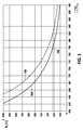
- FIG. 3 Internal resistance R I a Nernst cell, for example, the cell 134 of the sensor element 118 according to FIG. 1 , plotted for typical sensor elements 118 as a function of temperature T of a ceramic solid electrolyte 132.
- the curve 164 shows a new sensor element
- the curve 166 shows the behavior of an aged sensor element.
- a desired operating point of a new sensor element is in FIG. 2 denoted 168.
- the temperature of the sensor element should ideally be set, for example, to 780 ° C., which corresponds to an internal resistance of 220 ⁇ for a new sensor element. If this internal resistance R I is used as a controlled variable, the curve 166 of the aged sensor element, on the other hand, shows that in the aged sensor element this internal resistance of 220 ⁇ corresponds to a temperature of 820 ° C., ie a deviation of 40 ° C. This deviation is sensitive to sensor accuracy. To reach this temperature of 820 ° C, however, a considerably higher heating capacity is required.
- FIG. 2 Thus, for example, at the output of the comparator 156 and / or at the output of the actuator 150 would provide higher values than compared to the new sensor element.
- the one or more control elements 162 such a deviation can be detected, and it can optionally appropriate countermeasures are taken by correction in the control step and by influencing the manipulated variable accordingly.
- FIG. 4 For example, various possibilities of superimposing a control and a regulation, with simultaneous implementation of the method described above and taking account of an exhaust gas temperature T G as a control variable, are described. Plotted here on the vertical axis a size that characterizes the heating power of the heater 124 and which is here designated U H. This may, for example, be the heater voltage, although other parameters characterizing the heating power may also be applied.
- U H This may, for example, be the heater voltage, although other parameters characterizing the heating power may also be applied.
- a pilot control for example by means of the control device 148.
- the in FIG. 4 plotted characteristics show which heating power U H must be provided at the temperature of the gas in the measurement gas space 112 of the drive device 114 to the sensor element at a constant temperature, for example, the 780 ° C according to FIG. 3 , to keep.
- curve 170 shows a characteristic of a new sensor element
- curve 172 shows a characteristic of an aged sensor element.
- Such characteristic curves 170, 172 can be stored, for example, in the controller 160, so that, for example, the values D and E in FIG. 2 can be selected accordingly.
- the influencing of the at least one manipulated variable in the at least one control step can be on different, in FIG. 4 illustrated ways are done.
- an absolute cap 174 can be made to a fixed limit value of the heating power.
- dynamic limit values for example in the form of a lower limit value 176 and / or an upper limit value 178, which can be arranged, for example, around the characteristic curves 170, 172.
Landscapes
- Chemical & Material Sciences (AREA)
- Engineering & Computer Science (AREA)
- General Physics & Mathematics (AREA)
- Life Sciences & Earth Sciences (AREA)
- Health & Medical Sciences (AREA)
- Physics & Mathematics (AREA)
- Chemical Kinetics & Catalysis (AREA)
- General Health & Medical Sciences (AREA)
- Analytical Chemistry (AREA)
- Biochemistry (AREA)
- Immunology (AREA)
- Pathology (AREA)
- Automation & Control Theory (AREA)
- General Engineering & Computer Science (AREA)
- Mechanical Engineering (AREA)
- Molecular Biology (AREA)
- Electrochemistry (AREA)
- Combustion & Propulsion (AREA)
- Combined Controls Of Internal Combustion Engines (AREA)
- Measuring Oxygen Concentration In Cells (AREA)
Description
Aus dem Stand der Technik ist eine Vielzahl von Sensorelementen zur Erfassung mindestens einer Eigenschaft eines Gases in einem Messgasraum bekannt. Dabei kann es sich grundsätzlich um eine beliebige Eigenschaft des Gases handeln, beispielsweise eine physikalische und/oder chemische Eigenschaft des Gases. Insbesondere wird die Erfindung im Folgenden beschrieben unter Bezugnahme auf Sensorelemente zur Erfassung eines Anteils, also beispielsweise eines Partialdrucks und/oder eines Prozentsatzes, mindestens einer Gaskomponente in dem Gas. Bei der Gaskomponente kann es sich insbesondere um Sauerstoff handeln. Auch andere Gaskomponenten können jedoch alternativ oder zusätzlich nachgewiesen werden, beispielsweise Stickoxide, Kohlenwasserstoffe oder andere Gaskomponenten. Die Erfindung ist jedoch nicht auf den Nachweis von Gaskomponenten beschränkt, sondern es können grundsätzlich, alternativ oder zusätzlich, auch andere Eigenschaften des Gases nachgewiesen werden.From the prior art, a plurality of sensor elements for detecting at least one property of a gas in a sample gas space is known. In principle, this can be any property of the gas, for example a physical and / or chemical property of the gas. In particular, the invention will be described below with reference to sensor elements for detecting a proportion, ie for example a partial pressure and / or a percentage, of at least one gas component in the gas. The gas component may in particular be oxygen. However, other gas components can alternatively or additionally be detected, for example nitrogen oxides, hydrocarbons or other gas components. However, the invention is not limited to the detection of gas components, but in principle, alternatively or additionally, other properties of the gas can be detected.
Zum Nachweis von Gaskomponenten werden insbesondere Sensorelemente eingesetzt, welche auf der Verwendung mindestens eines Festelektrolyten, also eines ionenleitenden Festkörpers, beispielsweise eines Sauerstoff-Ionen leitenden Festkörpers, basieren. Derartige Festelektrolyte können beispielsweise auf Zirkoniumdioxid-Basis erstellt werden, beispielsweise Yttrium-stabilisiertes Zirkoniumdioxid und/oder Scandiumdotiertes Zirkoniumdioxid. Derartige Sensorelemente werden beispielsweise im Kraftfahrzeugbereich eingesetzt, um Gaskomponenten im Abgas einer Verbrennungsmaschine mit mindestens einem Motor nachzuweisen. Beispiele derartiger Sensorelemente sind in
Eine Lambdasonde beruht in der Regel auf der Verwendung mindestens einer galvanischen Sauerstoffkonzentrationszelle mit mindestens einem Festelektrolyt. Alternativ oder zusätzlich können auch sogenannte Pumpzellen eingesetzt werden. Lambdasonden können einen einzelligen oder auch einen mehrzelligen Aufbau aufweisen, wobei ebenfalls exemplarisch auf den genannten Stand der Technik verwiesen werden kann. In der Regel weisen derartige Sensorelemente mindestens eine Heizvorrichtung auf. So wird der Festelektrolyt typischerweise bei einer Aktivierungstemperatur von ca. 350°C für Sauerstoffionen leitend. Die Nominaltemperatur üblicher Lambdasonden liegt in der Regel deutlich höher, beispielsweise bei 650°C-850°C. Um die Nominaltemperatur unabhängig von den Umgebungsbedingungen, beispielsweise der Temperatur des Abgases, zu erreichen, wird das Sensorelement in der Regel aktiv elektrisch beheizt. Aus diesem Grund verfügen die meisten Sensorelemente der genannten Art über mindestens ein elektrisches Heizelement, welches im Folgenden allgemein auch als Heizvorrichtung bezeichnet wird und welches in der Regel von mindestens einem Steuergerät angesteuert wird. Beispielsweise weisen bekannte Lambdasonden auf Zirkoniumdioxid-Basis einen integrierten Platin-Heizer auf, der in der Regel so ausgelegt ist, dass dieser unter normalen Betriebsbedingungen eine größere Heizleistungsreserve aufweist. Dies bedeutet, dass die für den Betrieb des Sensorelements erforderliche Heizerspannung oder Heizleistung in der Regel deutlich kleiner ist als die zur Verfügung stehende Versorgungsspannung oder Versorgungsleistung. Beispielsweise werden bei typischen Sensorelementen der oben genannten Art Betriebstemperaturen von 780°C bereits mit Heizerspannungen von weniger als 8 V erreicht. In vielen Fällen wird das Sensorelement dabei nicht mit einer Gleichspannung sondern mit einer getakteten Effektivspannung betrieben, die durch Pulsweitenmodulation einer höheren Gleichspannung (Batteriespannung) erzeugt wird. Dementsprechend kann unter dem Begriff einer Heizerspannung im Folgenden sowohl die tatsächliche Spannung verstanden werden, mit welcher die Heizvorrichtung beaufschlagt wird, als auch alternativ eine effektive Spannung.A lambda probe is generally based on the use of at least one galvanic oxygen concentration cell with at least one solid electrolyte. Alternatively or additionally, so-called pump cells can also be used. Lambda probes may have a unicellular or else a multicellular structure, wherein reference may likewise be made by way of example to the cited prior art. As a rule, such sensor elements have at least one heating device. Thus, the solid electrolyte typically becomes conductive at an activation temperature of about 350 ° C for oxygen ions. The nominal temperature of conventional lambda probes is generally much higher, for example at 650 ° C-850 ° C. In order to achieve the nominal temperature regardless of the ambient conditions, for example the temperature of the exhaust gas, the sensor element is usually actively electrically heated. For this reason, most sensor elements of the type mentioned have at least one electrical heating element, which is also generally referred to below as a heating device and which is usually controlled by at least one control unit. For example, known zirconia-based lambda probes have an integrated platinum heater which is typically designed to have a larger heat capacity reserve under normal operating conditions. This means that the required for the operation of the sensor element heater voltage or heating power is usually much smaller than the available supply voltage or power supply. For example, operating temperatures of 780 ° C are already achieved with heater voltages of less than 8 V in typical sensor elements of the type mentioned above. In many cases, the sensor element is not operated with a DC voltage but with a clocked RMS voltage, which is generated by pulse width modulation of a higher DC voltage (battery voltage). Accordingly, the term heater voltage may be understood below to mean both the actual voltage applied to the heater and, alternatively, an effective voltage.
Das Ausgangssignal eines Sensorelements der oben genannten Art ist in der Regel funktional stark abhängig von der Temperatur des Sensorelements. Zur Verbesserung der Signalgenauigkeit ist es daher anzustreben, die Temperatur des Sensorelements von Änderungen der Abgastemperatur zu entkoppeln und möglichst konstant zu halten. Üblich ist zum Beispiel eine Temperatursteuerung der Heizerspannung einer Sprungsonde über ein betriebspunktabhängiges Kennfeld mit den Eingangsgrößen einer Abgastemperatur und einem Abgasmassenstrom. Eine erhöhte Temperaturgenauigkeit ergibt sich durch eine Temperaturregelung des Sensorelements. Als Regelgröße kann zum Beispiel ein Innenwiderstand Ri des Sensorelements verwendet werden, beispielsweise mindestens einer Zelle des Sensorelements, da in der Regel ein eindeutiger Zusammenhang zwischen dem Innenwiderstand und der Temperatur des Sensorelements besteht. Beispielsweise entspricht bei kommerziell erhältlichen Sprungsonden ein Innenwiderstand von 220 Ω einer Sensorelementtemperatur von 780°C. Eine entsprechende Temperaturregelung kommt auch in Breitbandsonden zum Einsatz.The output signal of a sensor element of the abovementioned type is generally functionally strongly dependent on the temperature of the sensor element. To improve the signal accuracy, it is therefore desirable to decouple the temperature of the sensor element from changes in the exhaust gas temperature and to keep it as constant as possible. For example, a temperature control of the heater voltage of a jump probe via an operating point-dependent characteristic map with the input variables of an exhaust gas temperature and an exhaust gas mass flow is customary. An increased temperature accuracy results from a temperature control of the sensor element. As a control variable, for example, an internal resistance R i of the sensor element can be used, for example, at least one cell of the sensor element, since there is usually a clear relationship between the internal resistance and the temperature of the sensor element. For example, in the case of commercially available jump probes, an internal resistance of 220 Ω corresponds to a sensor element temperature of 780 ° C. A corresponding temperature control is also used in broadband probes.
Trotz der Verbesserung der Signalgenauigkeiten durch existierende Regelungen besteht nach wie vor Bedarf und Verbesserungspotential für exaktere Temperatureinstellungen, um die Signalgenauigkeit der Sensorelemente weiter zu verbessern. Insbesondere soll die Betriebstemperatur des Sensorelements unabhängig von der Abgastemperatur einstellbar sein, um die Signalgenauigkeit weiter zu erhöhen und damit wiederum geringere Emissionen und robustere Diagnosen zu ermöglichen. Gleichzeitig soll eine Ansteuerung mit einer hohen Heizleistungsreserve möglich sein, ohne dass die Gefahr der Zerstörung des Sensorelements durch eine Überhitzung bei Beheizung im grundsätzlich zusätzlichen Bordnetzspannungsbereich besteht. Weiterhin soll das Sensorelement einer Abgassonde bei möglichst konstanter Temperatur betreibbar sein und gleichzeitig vor Überhitzung geschützt werden.Despite the improvement in signal accuracy by existing controls, there is still a need and potential for improvement in more accurate temperature settings to further improve signal accuracy of the sensor elements. In particular, the operating temperature of the sensor element should be adjustable independently of the exhaust gas temperature in order to further increase the accuracy of the signal and thus in turn enable lower emissions and more robust diagnoses. At the same time a control with a high heating power reserve should be possible without the risk of destruction of the sensor element by overheating when heating in basically additional vehicle electrical system voltage range exists. Furthermore, the sensor element of an exhaust gas probe should be operable at as constant a temperature as possible and at the same time protected against overheating.
Die
Zur Verbesserung bekannter Sensorelemente und Verfahren zum Betreiben dieser Sensorelemente sowie zur zumindest teilweisen Realisierung der oben genannten Ziele werden dementsprechend ein Verfahren zur Einstellung einer Temperatur eines mittels einer Heizvorrichtung beheizbaren Sensorelements zur Erfassung mindestens einer Eigenschaft eines Gases in einem Messgasraum sowie eine Sensorvorrichtung zur Erfassung mindestens einer Eigenschaft eines Gases in einem Messgasraum vorgeschlagen. Wie oben beschrieben, kann die Erfassung der mindestens einen Eigenschaft insbesondere eine Bestimmung eines Anteils einer Gaskomponenten in dem Gas sein. Bei der Gaskomponente kann es sich insbesondere um eine oder mehrere der Gaskomponenten Sauerstoff, Stickstoff, Stickoxide, Kohlenwasserstoffe oder andere Komponenten handeln. Bei dem Gas kann es sich insbesondere um ein Abgas handeln, insbesondere ein Abgas einer Verbrennungsmaschine, und bei dem Messgasraum insbesondere um einen Abgastrakt, beispielsweise einen Abgastrakt in einem Kraftfahrzeug. Auch andere Einsatzgebiete sind jedoch grundsätzlich möglich.Accordingly, in order to improve known sensor elements and methods for operating these sensor elements and to at least partially realize the abovementioned objectives, a method for setting a temperature of a sensor element which can be heated by means of a heating device for detecting at least one property of a gas in a measuring gas space and a sensor device for detecting at least one Property of a gas proposed in a sample gas space. As described above, the detection of the at least one property may in particular be a determination of a proportion of a gas component in the gas. The gas component may in particular be one or more of the gas components oxygen, nitrogen, nitrogen oxides, hydrocarbons or other components. The gas may in particular be an exhaust gas, in particular an exhaust gas of an internal combustion engine, and in the sample gas space, in particular an exhaust gas tract, for example an exhaust gas tract in a motor vehicle. However, other applications are possible in principle.
Das Verfahren dient zur Einstellung einer Temperatur des mittels einer Heizvorrichtung beheizbaren Sensorelements. Unter einer Einstellung einer Temperatur kann dabei eine Einstellung auf eine fest vorgegebene oder auch auf eine variabel vorgegebene Temperatur verstanden werden, wobei auch Temperaturverläufe vorgebbar sind. Unter einer Einstellung kann, wie unten noch näher ausgeführt wird, eine Steuerung und/oder eine Regelung der Temperatur subsummiert werden. Die Heizvorrichtung kann insbesondere eine resistive Heizvorrichtung umfassen, also beispielsweise mindestens einen Heizwiderstand, welcher beispielsweise durch Beaufschlagung mit einer Heizerspannung und/oder einem Heizerstrom resistiv beheizbar sein kann. Das vorgeschlagene Verfahren umfasst die im Folgenden beschriebenen Verfahrensschritte, welche vorzugsweise, jedoch nicht notwendigerweise, in der dargestellten Reihenfolge durchgeführt werden können. Einzelne oder mehrere Verfahrensschritte können auch zeitlich parallel, zeitlich überlappend oder einzeln oder zu mehreren wiederholt durchgeführt werden oder über längere Zeiträume durchgeführt werden. Das Verfahren kann darüber hinaus weitere, nicht aufgeführte Verfahrensschritte umfassen.The method is used to set a temperature of the heated by a heater sensor element. Under a setting of a temperature can be understood as a setting to a fixed predetermined or to a variably predetermined temperature, with temperature gradients can be specified. Under a setting, as will be explained in more detail below, a control and / or a regulation of the temperature can be subsumed. The heating device may in particular comprise a resistive heating device, that is to say for example at least one heating resistor, which may be resistively heated, for example by application of a heater voltage and / or a heater current. The proposed method comprises the method steps described below, which can preferably, but not necessarily, be carried out in the illustrated order. Individual or several method steps can also be carried out repeatedly in time, overlapping in time or individually or repeatedly, or be carried out over longer periods of time. The method may further include other unlisted method steps.
In einem ersten Verfahrensschritt wird mindestens ein Istwert mindestens einer Regelgröße des Sensorelements erfasst. Unter einer Regelgröße kann dabei grundsätzlich eine beliebige Messgröße des Sensorelements verstanden werden, welche für die Temperatureinstellung von Relevanz ist, insbesondere eine elektrische und/oder thermische Messgröße, welche direkt oder indirekt mit der Temperatur korreliert, also eine Messgröße, welche einen Rückschluss auf eine aktuelle Temperatur des Sensorelements oder eines Bereichs des Sensorelements ermöglicht. Beispiele von Regelgrößen werden unten noch näher erläutert. Anstelle der eigentlichen Messgröße können auch aus dieser Messgröße abgeleitete Größen verwendet werden, beispielsweise interpolierte, extrapolierte, gefilterte, verstärkte, digitalistisierte oder andere Werte. Unter einem Istwert der mindestens einen Regelgröße wird dabei ein aktueller Wert verstanden, also ein Messwert oder aus dem Messwert abgeleiteter Wert der Regelgröße, welcher zum gegenwärtigen Zeitpunkt oder zu einem Zeitpunkt erfasst wurde, welcher vorzugsweise nicht mehr als einige Sekunden, beispielsweise nicht mehr als 10 Sekunden, insbesondere nicht mehr als 5 Sekunden, vorzugsweise nicht mehr als 1 Sekunde oder sogar nicht mehr als 100 Millisekunden zurückliegt.In a first method step, at least one actual value of at least one controlled variable of the sensor element is detected. In this case, a controlled variable can basically be understood to mean any measured variable of the sensor element which is of relevance for the temperature setting, in particular an electrical and / or thermal measured variable which correlates directly or indirectly with the temperature, that is to say a measured variable which indicates a current temperature Temperature of the sensor element or a portion of the sensor element allows. Examples of controlled variables are explained in more detail below. Instead of the actual measured quantity, variables derived from this measured variable can also be used, for example interpolated, extrapolated, filtered, amplified, digitized or other values. In this context, an actual value of the at least one controlled variable is understood to be a current value, ie a measured value or value of the controlled variable derived from the measured value, which was detected at the present time or at a time, which is preferably not more than a few seconds, for example not more than 10 Seconds, in particular not more than 5 seconds, preferably not more than 1 second or even not more than 100 milliseconds ago.
In einem weiteren Verfahrensschritt wird mindestens ein Sollwert der zumindest einen Regelgröße ermittelt. Unter einem Sollwert wird dabei ein Wert der Regelgröße verstanden, auf welchen die Regelgröße exakt oder unter Vorgabe einer oder mehrerer Toleranzschwellen, eingestellt werden soll. Die Ermittlung des Sollwerts kann insbesondere dadurch erfolgen, dass dieser Sollwert von einer von dem Sensorelement getrennten Vorrichtung bereitgestellt wird, beispielsweise in dem dieser Sollwert fest vorgegeben wird oder, wie unten noch näher erläutert wird, unter Berücksichtigung mindestens einer Steuergröße, die den Einfluss einer Umgebung des Sensorelement auf die Temperatur des Sensorelements charakterisiert, bestimmt wird. Zur Ermittlung des Sollwerts können dementsprechend beispielsweise mindestens eine Datenverarbeitungsvorrichtung und/oder mindestens eine elektronische Tabelle und/oder eine andere Art von Vorrichtung vorgesehen sein, welche den mindestens einen Sollwert ermittelt und für das Verfahren bereitstellt.In a further method step, at least one desired value of the at least one controlled variable is determined. In this case, a setpoint value is understood to mean a value of the controlled variable to which the controlled variable is to be set exactly or with specification of one or more tolerance thresholds. The determination of the desired value can be effected, in particular, by providing this desired value from a device separate from the sensor element, for example by fixedly setting this desired value or, as will be explained below, taking into account at least one control variable which influences the environment of the sensor element is characterized on the temperature of the sensor element is determined. To determine the desired value, accordingly, for example, at least one data processing device and / or at least one electronic table and / or another type of device can be provided, which determines the at least one desired value and makes it available for the method.
In einem weiteren Verfahrensschritt wird mindestens eine Stellgröße der Heizvorrichtung mittels mindestens eines Vergleichs des Sollwerts und des Istwerts erzeugt. Unter einer Stellgröße ist dabei eine Größe, vorzugsweise ein elektrisches Signal und/oder eine digitale Information, zu verstehen, mittels derer die Heizvorrichtung unmittelbar oder indirekt angesteuert werden kann. Diese Stellgröße kann somit beispielsweise, wie unten noch näher ausgeführt wird, beispielsweise eine Heizleistung, eine Heizerspannung (wobei aktuelle oder auch effektive Heizerspannungen verwendet werden können), einen Heizstrom oder ähnliche Größen umfassen, mittels derer die Heizvorrichtung unmittelbar beaufschlagt werden kann. Alternativ oder zusätzlich kann die mindestens eine Stellgröße optional jedoch auch derart ausgestaltet sein, dass diese zunächst weiterverarbeitet werden muss, bevor diese zur Beaufschlagung der Heizvorrichtung dient, wobei beispielsweise mindestens ein Stellglied (beispielsweise mindestens ein Heizspannungsgenerator und/oder mindestens ein Verstärker) eingesetzt werden können.In a further method step, at least one manipulated variable of the heating device is generated by means of at least one comparison of the setpoint value and the actual value. A manipulated variable is understood to be a variable, preferably an electrical signal and / or digital information, by means of which the heating device can be controlled directly or indirectly. This manipulated variable can thus, for example, as described below, for example, a heating power, a heater voltage (current or effective heater voltages can be used), a heating current or similar sizes include, by means of which the heater can be applied directly. Alternatively or additionally, however, the at least one manipulated variable can optionally also be configured such that it must first be processed before it serves to act on the heating device, wherein, for example, at least one actuator (for example at least one heating voltage generator and / or at least one amplifier) can be used ,
In einem weiteren Verfahrensschritt wird mindestens ein Kontrollschritt durchgeführt. In diesem Kontrollschritt wird mindestens ein zur Einstellung der Temperatur mittels des vorgeschlagenen Verfahrens verwendeter Parameter überprüft und die mindestens eine Stellgröße in Abhängigkeit von der Überprüfung beeinflusst. Der zur Einstellung der Temperatur verwendeten Parameter ist die Stellgröße selbst. Unter einer Überprüfung kann insbesondere, wie unten ebenfalls noch näher ausgeführt wird, eine Abfrage verstanden werden, ob der mindestens eine Parameter mindestens einer vorgegebenen Bedingung genügt oder nicht. Beispielsweise können, wie unten noch näher ausgeführt wird, eine oder mehrere Schwellwertbedingungen vorgegeben werden. Unter einer Beeinflussung der mindestens einen Stellgröße in Abhängigkeit von der Überprüfung kann dabei eine direkte oder indirekte Beeinflussung der Stellgröße verstanden werden, beispielsweise indem die Stellgröße oder eine auf die Stellgröße einwirkende, vorgeschaltete Größe gezielt verändert wird. Die Beeinflussung erfolgt erfindungsgemäß derart, dass die Stellgröße auf einen sicheren Wert limitiert wird, wenn der mindestens eine Parameter, für eine gewisse Zeit einen Grenzwert über- oder unterschreitet. In a further method step, at least one control step is carried out. In this control step, at least one parameter used for setting the temperature by means of the proposed method is checked and the at least one manipulated variable is influenced as a function of the check. The parameter used for setting the temperature is the manipulated variable itself. Under a check can be understood in particular, as will also be explained in more detail below, a query whether the at least one parameter at least one predetermined Condition is enough or not. For example, as will be explained below, one or more threshold conditions may be specified. An influencing of the at least one manipulated variable as a function of the checking can be understood to be a direct or indirect influencing of the manipulated variable, for example by the manipulated variable or an upstream variable acting on the manipulated variable being specifically changed. The influencing takes place according to the invention such that the manipulated variable is limited to a safe value if the at least one parameter exceeds or falls below a limit value for a certain time.
Nach Durchführung der genannten Verfahrensschritte kann die Heizvorrichtung insbesondere mit der mindestens einen Stellgröße und/oder mit mindestens einer aus der Stellgröße abgeleiteten weiteren Stellgröße, beispielsweise unter Zwischenschaltung eines oder mehrerer Stellglieder, beaufschlagt werden. Die Korrektur der Stellgröße folgt vorzugsweise vor der Beaufschlagung der Heizvorrichtung.After carrying out the above-mentioned method steps, the heating device can be acted upon in particular by the at least one manipulated variable and / or by at least one further manipulated variable derived from the manipulated variable, for example by interposing one or more actuators. The correction of the manipulated variable preferably follows before the heating device is charged.
Besonders bevorzugt ist es, wenn das Verfahren derart durchgeführt wird, dass weiterhin mindestens eine Steuergröße erfasst wird. Unter einer Steuergröße ist dabei eine beliebige Größe zu verstehen, welche einen Einfluss einer Umgebung des Sensorelements auf die Temperatur des Sensorelements charakterisiert. Insbesondere kann die Steuergröße mindestens einen der folgenden Parameter umfassen: eine Umgebungstemperatur des Sensorelements, insbesondere eine Gastemperatur, beispielsweise eine Abgastemperatur, in dem Messgasraum; einen Betriebsparameter einer das Gas beinhaltenden, generierenden oder verwendenden Vorrichtung, insbesondere einen Betriebsbereich einer Verbrennungsmaschine, vorzugsweise einen Motorbetriebspunkt; einen Parameter, der einen in der Umgebung des Sensorelements auftretenden Gasstrom charakterisiert, insbesondere quantifiziert, beispielsweise einen Volumenstrom und/oder Massenstrom des Gases, beispielsweise des Abgases; einen Parameter, der eine in der Umgebung des Sensorelements auftretende Temperatur charakterisiert und insbesondere quantifiziert, insbesondere eine Abgastemperatur, eine Katalysatortemperatur und/oder eine Rohrwandtemperatur; eine Motordrehzahl; einen Motor-Lastzustand. Diese mindestens eine Steuergröße wird bereits in derzeitigen Abgassystemen in Kraftfahrzeugen in der Regel erfasst, da beispielsweise Abgastemperaturen für den Betrieb von Katalysatoren von Bedeutung sind, da Motorbetriebspunkte von einer Motorsteuerung ohnehin erfasst werden und da auch Abgasströme (Massenströme und/oder Volumenströme) beispielsweise bei einer Abgasrückführung von Bedeutung sind. Insofern können beispielsweise ohnehin erfasste Parameter oder Kombinationen derartiger Parameter als Steuergrößen für das vorgeschlagene Verfahren verwendet werden. Auch andere Parameter sind jedoch alternativ oder zusätzlich einsetzbar.It is particularly preferred if the method is carried out such that at least one control variable is still detected. A control variable is to be understood to mean an arbitrary variable which characterizes an influence of an environment of the sensor element on the temperature of the sensor element. In particular, the control variable may comprise at least one of the following parameters: an ambient temperature of the sensor element, in particular a gas temperature, for example an exhaust gas temperature, in the sample gas space; an operating parameter of a device including, generating or using the gas, in particular an operating range of an internal combustion engine, preferably an engine operating point; a parameter that characterizes, in particular quantifies, a gas stream occurring in the vicinity of the sensor element, for example a volume flow and / or mass flow of the gas, for example the exhaust gas; a parameter that characterizes and in particular quantifies a temperature occurring in the vicinity of the sensor element, in particular an exhaust gas temperature, a catalyst temperature and / or a tube wall temperature; an engine speed; an engine load condition. This at least one control variable is already detected in current exhaust systems in motor vehicles usually because, for example, exhaust gas temperatures for the operation of catalysts are important because engine operating points are detected by an engine control anyway and there also exhaust streams (mass flows and / or flow rates), for example at a Exhaust gas recirculation are of importance. In this respect, for example, recorded anyway Parameters or combinations of such parameters can be used as control variables for the proposed method. However, other parameters are alternatively or additionally applicable.
Wie oben dargestellt, umfasst das vorgeschlagene Verfahren eine Regelung der Heizvorrichtung. Optional kann diese Regelung mindestens eine Steuerung der Heizvorrichtung überlagert werden. Während bei einer Regelung aufgrund eines Vergleichs des Sollwerts und des Istwerts mindestens eine Stellgröße erzeugt wird, vorzugsweise automatisch, wobei eine Rückkopplung mit einem geschlossenen Wirkungskreis entstehen kann, erfolgt bei einer Steuerung lediglich eine Vorgabe einer Steuer-Führungsgröße, welche dann in der Steuerung in eine entsprechende Steuerstellgröße umgewandelt wird, ohne dass ein geschlossener Wirkungskreis verwendet wird. Die bei der Steuerung erzeugte mindestens eine Steuer-Stellgröße kann dabei der bei der Regelung erzeugten Stellgröße beispielsweise additiv, multiplikativ, subtraktiv oder auf andere Weise überlagert werden. Derartige Überlagerungen sind aus dem Stand der Technik grundsätzlich bekannt. Beispielsweise kann vor der Überlagerung eine unterschiedliche Verstärkung der bei der Regelung und bei der Steuerung erzeugten Stellgrößen folgen. Auch andere Arten der Überlagerung sind jedoch möglich. Die Überlagerung kann vor oder nach einem optionalen Stellglied erfolgen, beispielsweise vor oder nach einem Heizspannungsgenerator. Alternativ oder zusätzlich können auch für die Steuerung und für die Regelung unterschiedliche Stellglieder verwendet werden, beispielsweise jeweils eigenständige Heizspannungsgeneratoren, welche jeweils unabhängig voneinander Heizspannungen generieren, die anschließend, vor Beaufschlagung der mindestens einen Heizvorrichtung, überlagert werden können.As indicated above, the proposed method includes regulation of the heater. Optionally, this control can be superimposed at least one control of the heater. While at least one manipulated variable is generated during a control based on a comparison of the setpoint and the actual value, preferably automatically, wherein a feedback with a closed circuit can occur, only a default of a control command variable, which then in the controller in a corresponding control variable is converted without a closed circuit is used. The at least one control manipulated variable generated during the control can be superimposed, for example, additively, multiplicatively, subtractively or in some other way, the manipulated variable generated during the control. Such overlays are basically known from the prior art. For example, before the superimposition, a different amplification of the manipulated variables generated in the control and in the control can follow. However, other types of superposition are possible. The overlay can be done before or after an optional actuator, for example, before or after a heater voltage generator. Alternatively or additionally, different actuators can also be used for the control and for the control, for example independent heating voltage generators which each generate heating voltages independently of one another, which can then be superimposed before the at least one heating device is acted upon.
Die Steuerung der Heizvorrichtung kann insbesondere unter Berücksichtigung der mindestens einen Steuergröße erfolgen, beispielsweise einer oder mehreren der oben genannten Steuergrößen, welche einen Einfluss der Umgebung des Sensorelements auf die Temperatur des Sensorelements charakterisieren. Dabei können für die Regelung und die Steuerung jeweils dieselben Steuergrößen verwendet werden oder auch unterschiedliche Steuergrößen.The control of the heating device can take place in particular taking into account the at least one control variable, for example one or more of the above-mentioned control variables, which characterize an influence of the environment of the sensor element on the temperature of the sensor element. In each case, the same control variables can be used for the control and the control or different control variables.
Die Ermittlung des oben beschriebenen Sollwerts kann insbesondere unter Berücksichtigung der mindestens einen Steuergröße erfolgen. Dies bedeutet, dass die Regelung auf die mindestens eine Steuergröße angepasst werden kann, die einen Einfluss einer Umgebung des Sensorelements auf die Temperatur des Sensorelements charakterisiert. Alternativ oder zusätzlich kann auch die Steuerung unter Berücksichtigung der mindestens einen Steuergröße erfolgen, beispielsweise indem eine Steuer-Führungsgröße entsprechend der mindestens einen Steuergröße ausgewählt wird. So kann beispielsweise die Temperatur des Gases in dem Messgasraum und/oder eine Strömung des Gases in dem Messgasraum berücksichtigt werden. Ist beispielsweise die Abgastemperatur hoch, so genügt in der Regel eine geringere Heizleistung, um beispielsweise die Temperatur des Sensorelements auf den entsprechenden Sollwert einzustellen.The determination of the desired value described above can take place in particular taking into account the at least one control variable. This means that the control can be adapted to the at least one control variable, which influences the environment of the sensor element to the temperature of the sensor element characterized. Alternatively or additionally, the control can also take place taking into account the at least one control variable, for example by selecting a control command variable corresponding to the at least one control variable. For example, the temperature of the gas in the measuring gas space and / or a flow of the gas in the measuring gas space can be taken into account. If, for example, the exhaust gas temperature is high, a lower heating power is generally sufficient, for example, to set the temperature of the sensor element to the corresponding desired value.
Die mindestens eine Regelgröße kann insbesondere eine oder mehrere der folgenden Regelgrößen umfassen: mindestens einen Innenwiderstand des Sensorelements, insbesondere einen Innenwiderstand mindestens einer elektrochemischen Zelle des Sensorelements, also einer Kombination aus mindestens zwei Elektroden und mindestens einem die mindestens zwei Elektroden verbindenden Festelektrolyten; eine Temperatur des Sensorelements, welche beispielsweise mittels eines separaten Temperatursensors erfassbar sein kann; eine Spannung zwischen mindestens zwei Elektroden des Sensorelements, insbesondere zwischen mindestens zwei Elektroden einer Nernstzelle des Sensorelements; einen Strom zwischen mindestens zwei Elektroden des Sensorelements, insbesondere zwischen mindestens zwei Elektroden einer Pumpzelle des Sensorelements; beispielsweise einen Strom bei einer fest vorgegebenen Pumpspannung; einen elektrischen Widerstand einer leitenden Struktur, insbesondere einer leitenden Struktur des Sensorelements, beispielsweise einen elektrischen Widerstand einer Metallstruktur, beispielsweise einen elektrischen Widerstand einer Zuleitung und/oder eines metallischen Mäanders. Auch andere Regelgrößen oder Kombinationen der genannten und/oder andere Regelgrößen sind denkbar. Besonders bevorzugt ist die Verwendung mindestens eines Innenwiderstands oder mindestens einer den Innenwiderstand des Sensorelements charakterisierenden Größe als Regelgröße. Beispielsweise kann dieser Innenwiderstand dadurch gemessen werden, dass mindestens eine elektrochemische Zelle des Sensorelements kurzfristig mit einem Spannungs- und/oder Strompuls beaufschlagt wird und die jeweils andere Größe, beispielsweise Strom bzw. Spannung gemessen wird. Diese Innenwiderstandsmessung kann zeitlich überlagert zu sonstigen Messungen des Sensorelements zur Erfassung der mindestens einen Eigenschaft des Gases durchgeführt werden oder auch intermittierend, beispielsweise indem die eigentliche Erfassung der Eigenschaft kurzfristig unterbrochen wird. So kann beispielsweise eine eigentlich als Nernstzelle verwendete Zelle des Sensorelements kurzfristig für eine Temperaturmessung eingesetzt werden.The at least one controlled variable may in particular comprise one or more of the following control variables: at least one internal resistance of the sensor element, in particular an internal resistance of at least one electrochemical cell of the sensor element, ie a combination of at least two electrodes and at least one solid electrolyte connecting the at least two electrodes; a temperature of the sensor element, which may be detectable for example by means of a separate temperature sensor; a voltage between at least two electrodes of the sensor element, in particular between at least two electrodes of a Nernst cell of the sensor element; a current between at least two electrodes of the sensor element, in particular between at least two electrodes of a pumping cell of the sensor element; for example, a current at a fixed pump voltage; an electrical resistance of a conductive structure, in particular a conductive structure of the sensor element, for example an electrical resistance of a metal structure, for example an electrical resistance of a supply line and / or a metallic meander. Other controlled variables or combinations of the mentioned and / or other controlled variables are also conceivable. Particularly preferred is the use of at least one internal resistance or at least one of the internal resistance of the sensor element characterizing size as a controlled variable. For example, this internal resistance can be measured in that at least one electrochemical cell of the sensor element is briefly acted upon by a voltage and / or current pulse and the respective other variable, for example current or voltage, is measured. This internal resistance measurement can be superimposed over time to other measurements of the sensor element for detecting the at least one property of the gas or intermittently, for example by the actual detection of the property is temporarily interrupted. For example, a cell of the sensor element actually used as a Nernst cell can be used for a temperature measurement at short notice.
Wie oben ausgeführt, kann die Stellgröße insbesondere eine Stellgröße sein, welche eine Heizleistung der Heizvorrichtung und damit einen Eintrag einer Wärmeenergie in das Sensorelement beeinflusst. Insbesondere kann die Stellgröße eine oder mehrere der folgenden Stellgrößen umfassen: eine an der Heizvorrichtung anliegende Heizerspannung; eine an der Heizvorrichtung anliegende Heizleistung; einen an der Heizvorrichtung anliegenden Heizstrom; einen Parameter einer Pulsweitenmodulation einer an der Heizvorrichtung anliegenden Heizleistung. Auch Kombinationen der genannten und/oder anderer Stellgrößen sind denkbar. Dabei können die genannten Stellgrößen direkt verwendet werden oder, wie oben erwähnt aus diesen Stellgrößen ableitbare oder diese Stellgröße generierende Größen.As stated above, the manipulated variable may in particular be a manipulated variable which influences a heating power of the heating device and thus an entry of thermal energy into the sensor element. In particular, the manipulated variable may include one or more of the following manipulated variables: a heater voltage applied to the heater; a heating power applied to the heater; a heating current applied to the heater; a parameter of a pulse width modulation of a heating power applied to the heater. Combinations of the mentioned and / or other manipulated variables are also conceivable. In this case, the aforementioned manipulated variables can be used directly or, as mentioned above, variables that can be derived from these manipulated variables or variables that generate this manipulated variable.
Wie oben ausgeführt, wird in dem Kontrollschritt mindestens ein zur Einstellung der Temperatur verwendeter Parameter überprüft. Dieser mindestens eine Parameter ist die Stellgröße.As stated above, at least one parameter used to adjust the temperature is checked in the control step. This at least one parameter is the manipulated variable.
Zusätzlich können weitere Parameter und/oder Kombinationen der genannten (Istwert der Regelgröße, Sollwert der Regelgröße, Steuergröße, welche einen Einfluss der Umgebung des Sensorelements auf die Temperatur des Sensorelements charakterisiert. Bezüglich der möglichen Ausgestaltungen der Steuergröße kann dabei auf die obige Beschreibung verwiesen werden) und/oder anderer Parameter verwendet werden. In dem Kontrollschritt können dabei die genannten und/oder andere Parameter als einzelne Werte überprüft werden, beispielsweise in dem ein Einzelwertvergleich mit mindestens einem Schwellwert erfolgt. Alternativ oder zusätzlich können jedoch auch für einzelne, mehrere oder alle der genannten Parameter zeitliche
Verläufe der Parameter überprüft werden, beispielsweise indem zeitliche Schwankungen, die Historie des Verlaufs der genannten Parameter, Mittelwerte der genannten Parameter über einen vorgegebenen Zeitraum hinweg, gefilterte Verläufe der genannten Parameter oder andere aus den zeitlichen Verläufen der genannten Parameter und/oder andere Parameter abgeleitete Sekundärparameter oder Funktionen ausgewertet werden. Beispiele werden unten noch näher erläutert.In addition, further parameters and / or combinations of the above-mentioned (actual value of the controlled variable, desired value of the controlled variable, control variable, which characterizes an influence of the environment of the sensor element on the temperature of the sensor element can be referred to with regard to the possible embodiments of the control variable). and / or other parameters. In the control step, the aforementioned and / or other parameters can be checked as individual values, for example by performing a single value comparison with at least one threshold value. Alternatively or additionally, however, temporal can also be used for individual, several or all of the mentioned parameters
Characteristics of the parameters are checked, for example, by temporal fluctuations, the history of the course of said parameters, averages of said parameters over a predetermined period of time, filtered waveforms of said parameters or other derived from the time courses of said parameters and / or other parameters secondary parameters or functions are evaluated. Examples are explained in more detail below.
Die Überprüfung des Parameters in dem Kontrollschritt kann, wie oben beschrieben, auf verschiedene Weisen ausgestaltet sein, die auch beliebig miteinander kombinierbar sind. Insbesondere kann die Überprüfung des Parameters eine Abfrage umfassen, ob der Parameter (worunter, wie oben ausgeführt, ein einzelner Wert, mehrere Werte, abgeleitete Werte, Zeitverläufe oder ähnliche Werte zu verstehen sind) mindestens einem fest oder dynamisch vorgegebenen Schwellwert erreicht, unterschreitet oder überschreitet und optional gegebenenfalls wie lange dies der Fall ist. Beispielsweise kann mindestens eine Bedingung derart lauten, dass der Parameter einen vorgegebenen Schwellwert unterschreiten soll oder nicht überschreiten soll. Auch eine Bedingung, dass der Parameter einen vorgegebenen Schwellwert überschreiten oder nicht unterschreiten soll, kann vorgegeben werden. Der Schwellwert kann fest vorgegeben sein oder auch variabel, also dynamisch, beispielsweise angepasst auf eine oder mehrere externe Steuergrößen und/oder andere externe Parameter. Alternativ oder zusätzlich kann die Überprüfung auch eine Abfrage umfassen, ob eine zeitliche Schwankung des Parameters über einen Messzeitraum hinweg eine vorgegebene Maximalschwankung unterschreitet, erreicht oder überschreitet und optional gegebenenfalls wie lange dies der Fall ist. Entsprechend können auch hier bezüglich der Schwankungen gewisse Bedingungen gesetzt werden, wiederum alternativ oder zusätzlich kann der Kontrollschritt eine Überprüfung in Form eines Vergleichs eines zeitlichen Verlaufs des Parameters mit mindestens einem Sollverlauf umfassen. Ein derartiger Vergleich kann beispielsweise durch einen Vergleich von Kurven, Funktionen, Einzelwerten, mehreren Werten oder auf ähnliche Weise erfolgen. Beispielsweise können Abweichungen, Fehlerquadrate, Korrelationsfunktionen oder ähnliche Vergleiche herangezogen werden, um eine Übereinstimmung und/oder eine Abweichung des Verlaufs von dem Sollverlauf zu quantifizieren. Auch Kombinationen der genannten Überprüfungen untereinander und/oder mit anderen Überprüfungen sind möglich. Beispiele werden unten noch näher ausgeführt.The checking of the parameter in the control step can, as described above, be configured in various ways, which can also be combined with one another as desired. In particular, the checking of the parameter may include a query as to whether the parameter (which, as explained above, is a single value, a plurality of values, derived values, time courses or similar values) reaches, falls below or exceeds at least one fixed or dynamically predetermined threshold value and, optionally, how long this is the case. For example, at least one condition may be such that the parameter should be less than or less than a predetermined threshold. Also, a condition that the parameter should exceed a predetermined threshold or not fall below, can be specified. The threshold value can be fixed or variable, that is dynamic, for example, adapted to one or more external control variables and / or other external parameters. Alternatively or additionally, the check may also include a query as to whether a temporal fluctuation of the parameter over a measurement period falls short of, reaches or exceeds a predefined maximum fluctuation and, optionally, how long this is the case. Accordingly, certain conditions can also be set here with regard to the fluctuations, again alternatively or additionally, the checking step may include a check in the form of a comparison of a time profile of the parameter with at least one desired course. Such a comparison may be made, for example, by a comparison of curves, functions, individual values, multiple values, or the like. For example, deviations, error squares, correlation functions or similar comparisons can be used to quantify a match and / or a deviation of the course from the target profile. It is also possible to combine the aforementioned checks with one another and / or with other checks. Examples will be discussed below.
Weitere bevorzugte Ausgestaltungen des Verfahrens betreffen die Art der Beeinflussung der Stellgröße in dem Kontrollschritt. So kann diese Beeinflussung insbesondere eine oder mehrere der im Folgenden beschrieben Beeinflussungen umfassen. Beispielsweise kann die Beeinflussung eine Verwerfung eines einzelnen oder mehrerer Werte des Parameters und/oder eine darauf resultierende Beeinflussung der Stellgröße umfassen. Insbesondere kann eine Verwerfung stark schwankender zeitlicher Messwerte des Parameters erfolgen, beispielsweise eine Verwerfung von Messwerten des Parameters, welche außerhalb eines vorgegebenen Toleranzbereichs, beispielsweise eines vorgegebenen Toleranzbereichs um einen zeitlichen Mittelwert, liegen. Alternativ oder zusätzlich können eine Filterung des Istwerts und eine daraus resultierende Beeinflussung der Stellgröße erfolgen. Eine Filterung kann beispielsweise mittels eines Tiefpassfilters und/oder mittels eines Bandpassfilters erfolgen. Wiederum alternativ oder zusätzlich kann die Beeinflussung auch mindestens einen Mittelwertbildung des Istwerts und eine daraus resultierende Beeinflussung der Stellgröße umfassen. So kann beispielsweise ein Istwert über einen gewissen Zeitraum hinweg gemittelt werden, wobei beispielsweise ein geometrisches Mittel und/oder ein arithmetisches Mittel gebildet werden kann. Wiederum alternativ oder zusätzlich kann die Stellgröße auch durch einen fest oder dynamisch vorgegebenen Minimalwert oder Maximalwert ersetzt werden. Beispielsweise kann eine feste Untergrenze und/oder eine feste Obergrenze für die mindestens eine Stellgröße vorgegeben werden. Eine dynamische Vorgabe kann beispielsweise als Abweichung um eine Steuer-Stellgröße erfolgen, wenn eine Steuerung der Regelung überlagert wird. So kann beispielsweise um einen Steuer-Stellwert ein Toleranzbereich vorgegeben werden, innerhalb dessen die Stellgröße liegen soll. Beispiele werden unten noch näher beschrieben. Wiederum alternativ oder zusätzlich kann die Stellgröße auch auf einen Default-Wert gesetzt werden, beispielsweise 0 oder einen im Vergleich zu einem maximal möglichen Wert reduzierten Wert. Dies kann auch durch ein Abschalten einer Beaufschlagung der Heizvorrichtung mit Heizenergie erfolgen. Wiederum alternativ oder zusätzlich kann die Stellgröße um einen vorgegebenen Betrag oder einen vorgegebenen Korrekturfaktor verringert werden. Alternativ oder zusätzlich kann die Stellgröße auch mittels mindestens einer Korrekturfunktion in eine veränderte Stellgröße umgewandelt werden. Diese mindestens eine Korrekturfunktion kann grundsätzlich beliebige Korrekturen umfassen, beispielsweise Korrekturen mittels eines oder mehrerer Korrekturwerte, Korrekturfunktionen, Korrektur-Feldern oder ähnlichen, dem Fachmann grundsätzlich bekannten Korrekturen. Wiederum alternativ oder zusätzlich kann die Beeinflussung auch eine Veränderung mindestens eines Regelkreises der Einstellung der Temperatur umfassen, insbesondere eine Abschaltung eines integralen Anteils des Regelkreises. Wiederum alternativ oder zusätzlich kann die Beeinflussung auch eine vollständige und/oder teilweise Abschaltung der Regelung umfassen, beispielsweise indem vollständig auf eine Steuerung der Heizvorrichtung umgeschaltet wird, beispielsweise eine Steuerung der oben beschriebenen Art.Further preferred embodiments of the method relate to the type of influencing the manipulated variable in the control step. So this influence can be a particular or more of the influences described below. By way of example, the influencing may include a rejection of one or more values of the parameter and / or a consequent influencing of the manipulated variable. In particular, a rejection of strongly fluctuating temporal measured values of the parameter can take place, for example a rejection of measured values of the parameter, which lie outside a predetermined tolerance range, for example a predetermined tolerance range around a temporal mean value. Alternatively or additionally, a filtering of the actual value and a resulting influencing of the manipulated variable can take place. A filtering can be done for example by means of a low-pass filter and / or by means of a bandpass filter. Again alternatively or additionally, the influencing may also include at least one averaging of the actual value and a resulting influencing of the manipulated variable. Thus, for example, an actual value can be averaged over a certain period of time, wherein, for example, a geometric mean and / or an arithmetic mean can be formed. Again alternatively or additionally, the manipulated variable can also be replaced by a fixed or dynamically predetermined minimum value or maximum value. For example, a fixed lower limit and / or a fixed upper limit for the at least one manipulated variable can be specified. A dynamic specification can for example be done as a deviation by a control manipulated variable when a control of the control is superimposed. For example, a tolerance range can be specified by a control manipulated variable within which the manipulated variable should lie. Examples will be described in more detail below. Again alternatively or additionally, the manipulated variable can also be set to a default value, for example 0 or a reduced value compared to a maximum possible value. This can also be done by switching off a loading of the heater with heating energy. Again alternatively or additionally, the manipulated variable can be reduced by a predetermined amount or a predetermined correction factor. Alternatively or additionally, the manipulated variable can also be converted into a modified manipulated variable by means of at least one correction function. This at least one correction function can in principle comprise any desired corrections, for example corrections by means of one or more correction values, correction functions, correction fields or similar corrections basically known to the person skilled in the art. Again alternatively or additionally, the influence may also include a change in at least one control loop of the setting of the temperature, in particular a shutdown of an integral part of the control loop. Again, alternatively or additionally, the influence can also be a complete and / or partial shutdown of the scheme include, for example, by completely switching to a control of the heater, such as a controller of the type described above.
In einem weiteren Aspekt der vorliegenden Erfindung wird eine Sensorvorrichtung zur Erfassung mindestens einer Eigenschaft eines Gases in einem Messgasraum vorgeschlagen, insbesondere zur Bestimmung eines Anteils einer Gaskomponente. Die Sensorvorrichtung umfasst mindestens ein Sensorelement zur Erfassung der Eigenschaft.In a further aspect of the present invention, a sensor device for detecting at least one property of a gas in a measurement gas space is proposed, in particular for determining a proportion of a gas component. The sensor device comprises at least one sensor element for detecting the property.
Die Sensorvorrichtung umfasst weiterhin mindestens eine Heizvorrichtung zur Beheizung zumindest eines Teils des Sensorelements. Beispielsweise kann die mindestens eine Heizvorrichtung ganz oder teilweise Bestandteil des Sensorelements sein. Alternativ oder zusätzlich kann die mindestens eine Heizvorrichtung jedoch auch ganz oder teilweise in anderer Weise in der Sensorvorrichtung aufgenommen sein, beispielsweise als externes Bauteil. Im ersten Fall kann die Heizvorrichtung beispielsweise in ein keramisches Sensorelement integriert sein, beispielsweise einen Schichtaufbau des keramischen Sensorelements, wie dies beispielsweise bei Planarsonden in der Regel der Fall ist. Im zweiten Fall kann die Heizvorrichtung beispielsweise als Stäbchenheizer ausgestaltet sein, wie dies beispielsweise bei Fingersonden in der Regel der Fall ist.The sensor device further comprises at least one heating device for heating at least a part of the sensor element. For example, the at least one heating device may be part of the sensor element wholly or partly. Alternatively or additionally, however, the at least one heating device can also be accommodated in a completely different manner in the sensor device, for example as an external component. In the first case, the heating device can be integrated, for example, in a ceramic sensor element, for example a layer structure of the ceramic sensor element, as is usually the case, for example, with planar probes. In the second case, the heating device can be designed, for example, as a rod heater, as is generally the case with finger probes, for example.
Beispielsweise kann das Sensorelement ein Sensorelement mit mindestens einem Festelektrolyten der oben beschriebenen Art sein, insbesondere einem keramischen Festelektrolyten. Das Sensorelement kann insbesondere eine oder mehrere Zellen umfassen, also zwei Elektroden, welche über die Festelektrolyten miteinander in Verbindung stehen. Das Sensorelement kann einzellig oder auch mehrzellig ausgestaltet sein. Bezüglich möglicher Ausgestaltungen des Sensorelements kann beispielsweise auf den oben beschriebenen Stand der Technik verwiesen werden. Grundsätzlich sind alle Arten von Sensorelementen erfindungsgemäß einsetzbar, insbesondere keramische Sensorelemente. Die Sensorvorrichtung umfasst weiterhin mindestens eine Ansteuervorrichtung. Die Ansteuervorrichtung ist eingerichtet, um ein Verfahren gemäß einem oder mehreren der vorhergehenden Ansprüche durchzuführen. Die Ansteuervorrichtung kann zentral oder auch dezentral ausgestaltet sein und kann vollständig oder teilweise Software-implementiert und/oder Hardware-implementiert sein. Die Ansteuervorrichtung kann auch ganz oder teilweise beispielsweise in eine zentrale Motorsteuerung implementiert sein. Die Ansteuervorrichtung kann beispielsweise eine Sensor-Ansteuervorrichtung zum Ansteuern und/oder Auswerten des Sensorelements bzw. von Signalen des Sensorelements umfassen. Zur Implementierung des genannten Verfahrens kann die Ansteuervorrichtung weiterhin beispielsweise mindestens eine Regelvorrichtung umfassen, in welcher beispielsweise mindestens ein Regler enthalten sein kann. Zur Überlagerung einer optionalen Steuerung kann die Ansteuervorrichtung weiterhin mindestens eine Steuervorrichtung umfassen. Die Regelvorrichtung und die Steuervorrichtung können zusammen eine Heizelement-Ansteuervorrichtung bilden.For example, the sensor element may be a sensor element having at least one solid electrolyte of the type described above, in particular a ceramic solid electrolyte. The sensor element may in particular comprise one or more cells, that is to say two electrodes, which communicate with one another via the solid electrolytes. The sensor element can be designed unicellular or multicellular. With respect to possible embodiments of the sensor element, reference may be made, for example, to the prior art described above. In principle, all types of sensor elements can be used according to the invention, in particular ceramic sensor elements. The sensor device further comprises at least one drive device. The drive device is set up to carry out a method according to one or more of the preceding claims. The control device can be configured centrally or else decentrally and can be completely or partially software implemented and / or hardware implemented. The drive device can also be completely or partially implemented, for example, in a central motor control. The drive device may comprise, for example, a sensor drive device for driving and / or evaluating the sensor element or signals of the sensor element. To implement the mentioned Method, the drive device may further comprise, for example, at least one control device, in which, for example, at least one controller may be included. For superposition of an optional control, the drive device may further comprise at least one control device. The control device and the control device may together constitute a heater driving device.
Das vorgeschlagene Verfahren und die vorgeschlagene Sensorvorrichtung weisen gegenüber bekannten Verfahren und Sensorvorrichtungen zahlreiche Vorteile auf. So kann insbesondere ein Sensorelement mit der Eigenschaft einer hohen Heizleistungsreserve realisiert werden, die zur Zerstörung des Sensorelements durch Überhitzung bei Beheizung im grundsätzlich zulässigen Bordnetzspannungsbereich führen könnte. Dieses Sensorelement und die Sensorvorrichtung können jedoch unabhängig vom Motorbetriebspunkt bei konstanter Temperatur betrieben werden und gleichzeitig derart eingerichtet sein, dass das Sensorelement vor einer Überhitzung geschützt werden kann. Das Verfahren lässt sich grundsätzlich auf alle aktiv beheizten und temperaturgeregelten oder temperaturgesteuerten Abgassensoren anwenden.The proposed method and the proposed sensor device have numerous advantages over known methods and sensor devices. Thus, in particular, a sensor element with the property of a high heating power reserve can be realized, which could lead to the destruction of the sensor element by overheating when heating in basically permissible board voltage range. However, this sensor element and the sensor device can be operated independently of the engine operating point at a constant temperature and at the same time be set up such that the sensor element can be protected against overheating. The method can basically be applied to all actively heated and temperature-controlled or temperature-controlled exhaust gas sensors.
Um die Sensorelementtemperatur möglichst konstant zu halten, können insbesondere eine Temperatursteuerung und eine Temperaturregelung kombiniert werden, wie oben beschrieben. Beispielsweise kann die Steuerung mittels eines Kennfeldes betrieben werden, beispielsweise in dem, wie oben beschrieben, ein oder mehrere Steuergrößen erfasst werden, die den Einfluss der Umgebung des Sensorelements auf die Temperatur des Sensorelements charakterisieren. Eine derartige Steuerung kann insbesondere als Kennfeldvorsteuerung ausgestaltet sein, welcher die genannte Regelung überlagert sein kann. Eine derartige Überlagerung einer Steuerung mit einer Regelung bietet den Vorteil der hohen Genauigkeit einer Regelung, kombiniert mit einer schnellen Reaktion auf Änderungen des Motorbetriebspunkts, beispielsweise bei abrupten Lastwechseln, durch die vorzugsweise betriebspunktabhängigen Steuerungen. Dadurch werden hohe Reglerhübe vermieden, und die Regelung kann beispielsweise lediglich zur Korrektur einer Steuer-Stellgröße, die durch die Steuerung erzeugt wird, eingesetzt werden. Die Steuer-Stellgröße wird im Folgenden auch als Vorsteuerwert bezeichnet. Dieses Verfahren kann allgemein zu einer verbesserten Temperaturstabilisierung eingesetzt werden. Für die Temperaturregelung, insbesondere einer Sprungsonde, kann insbesondere ein Innenwiderstand einer Nernstzelle durch einen kurzzeitigen Strompuls zwischen Mess- und Referenzelektrode des Sensorelements gemessen werden. Dieses Verfahren ist aus dem Stand der Technik grundsätzlich bekannt und wird dort allerdings in der Regel für Diagnosezwecke eingesetzt. Im Rahmen des oben vorgeschlagenen Verfahrens kann der derartig erfasste Innenwiderstand als Istwert der mindestens einen Regelgröße des Sensorelements oder als Teil eines Istwerts des Wertes verwendet werden. Der ermittelte Innenwiderstand kann dann für die Regelung der Temperatur verwendet werden. Der bei herkömmlichen Regelverfahren bei ungenauer oder fehlerhafter Erfassung der Regelgröße auftretende Nachteil, dass die optimale Betriebstemperatur überschritten oder unterschritten werden kann oder dass sich bei starker Überschreitung der Betriebstemperatur sogar Beschädigungen am Sensorelement einstellen können, kann jedoch durch den vorgeschlagenen Kontrollschritt vermieden werden. Wenn beispielsweise permanent oder temporär ein erhöhter Übergangswiderstand im Signalkreis des Sensorelements auftritt, beispielsweise in Form von Kontaktierungsproblemen, neigen herkömmliche Temperaturregelungen dazu, den hohen gemessenen Widerstand auf den kleineren Zielwiderstand einzuregeln und erhöhen dabei die Heizerspannung. Dadurch wird das Sensorelement zu heiß betrieben, und die im Sensorelement integrierte Heizvorrichtung kann durchbrennen. So würden beispielsweise herkömmliche Sensorelemente auf eine Temperatur von > 1150°C aufgeheizt, wenn diese längere Zeit mit einer Heizerspannung von 11 V betrieben werden, was zum Durchbrennen des Heizers führt. Je größer die Heizleistungsreserve der Heizvorrichtung, insbesondere einer in das Sensorelement integrierten Heizvorrichtung, ist, desto größer ist die Gefahr einer schädigenden Überhitzung des Sensorelements. Zur Vermeidung dieser Überhitzung wird bei dem erfindungsgemäßen Verfahren die Regelung der Temperatur vorgesehen, welche optional durch eine oder mehrere Steuergrößen modifiziert oder unterstützt werden kann, die beispielsweise von einem Motorsteuerungssystem bereitgestellt werden können.In order to keep the sensor element temperature as constant as possible, in particular a temperature control and a temperature control can be combined, as described above. For example, the controller can be operated by means of a characteristic diagram, for example in which, as described above, one or more control variables are detected which characterize the influence of the surroundings of the sensor element on the temperature of the sensor element. Such a control can in particular be designed as a map feedforward control, which can be superimposed on said control. Such a superposition of closed loop control provides the advantage of high accuracy closed loop control, combined with a rapid response to changes in engine operating point, for example during abrupt load changes, by the preferably operating point dependent controls. As a result, high controller strokes are avoided, and the control can be used, for example, only to correct a control manipulated variable generated by the controller. The control manipulated variable is also referred to below as the precontrol value. This method can generally be used for improved temperature stabilization. For the temperature control, in particular a jump probe, in particular an internal resistance of a Nernst cell can be measured by a short-time current pulse between the measuring and reference electrodes of the sensor element. This method is known in principle from the prior art and is there, however, in usually used for diagnostic purposes. In the context of the method proposed above, the internal resistance detected in this way can be used as the actual value of the at least one controlled variable of the sensor element or as part of an actual value of the value. The determined internal resistance can then be used for the regulation of the temperature. However, the disadvantage occurring in conventional control methods in the case of inaccurate or erroneous detection of the controlled variable that the optimum operating temperature can be exceeded or undershot or even damage to the sensor element can occur if the operating temperature is greatly exceeded, can be avoided by the proposed control step. If, for example, permanently or temporarily an increased contact resistance occurs in the signal circuit of the sensor element, for example in the form of contacting problems, conventional temperature controls tend to adjust the high measured resistance to the smaller target resistance and thereby increase the heater voltage. As a result, the sensor element is operated too hot, and the heating element integrated in the sensor element can burn out. Thus, for example, conventional sensor elements would be heated to a temperature of> 1150 ° C, if they are operated for a long time with a heater voltage of 11 V, resulting in the burning of the heater. The greater the heating power reserve of the heating device, in particular a heating device integrated in the sensor element, the greater the risk of damaging overheating of the sensor element. To avoid this overheating, the regulation of the temperature is provided in the method according to the invention, which can be optionally modified or supported by one or more control variables, which can be provided for example by an engine control system.
Bei dem vorgeschlagenen Verfahren kann insbesondere, wie oben beschrieben, bei der Überlagerung der Steuerung eine Kennfeld-basierte Vorsteuerung verwendet werden, mit welcher die vorgeschlagene Regelung überlagert werden kann oder mit welcher die vorgeschlagene Regelung auf andere Weise kombiniert werden kann. Diese Vorsteuerung kann insbesondere auf gemessenen oder modellierten Steuergrößen, welche auch als Kenngrößen bezeichnet werden, basieren, beispielsweise auf gemessenen oder modellierten Kenngrößen eines Abgassystems, die das Motorbetriebspunkt-abhängige Aufheiz- und Abkühlverhalten des Sensorelements gut widerspiegeln. Da eine feste Sensorelementtemperatur in der Regel einem festen Innenwiderstand des Sensorelements entspricht, kann die überlagerte Regelung zum Beispiel als PID-Regler umgesetzt werden, der den gemessenen Innenwiderstand Ri beispielsweise mit einem Sollwert vergleichen kann. Auf diese Weise kann eine Stellgröße ermittelt werden, die beispielsweise eine Heizerspannungskorrektur oder eine auf andere Weise gestaltete Korrektur der Heizleistung relativ zur Sollspannung der Vorsteuerung ausgeben kann. Eine Überhitzung des Sensorelements aufgrund fehlerhafter Innenwiderstandsregelung wird durch die erfindungsgemäßen Gegenmaßnahmen zumindest weitgehend vermieden.In the proposed method, in particular, as described above, in the superimposition of the control, a map-based feedforward control can be used, with which the proposed control can be superimposed or with which the proposed control can be combined in another way. This precontrol can be based, in particular, on measured or modeled control variables, which are also referred to as characteristic quantities, for example on measured or modeled characteristics of an exhaust system, which well reflect the engine operating point-dependent heating and cooling behavior of the sensor element. Since a fixed sensor element temperature generally corresponds to a fixed internal resistance of the sensor element, the superimposed control can be implemented as a PID controller, for example, which measures the measured internal resistance R i For example, compare with a setpoint. In this way, a manipulated variable can be determined, which can output, for example, a heater voltage correction or a differently designed correction of the heating power relative to the setpoint voltage of the pilot control. Overheating of the sensor element due to faulty internal resistance control is at least largely avoided by the countermeasures according to the invention.
Beispiele für Fehlermöglichkeiten einer Innenwiderstandsregelung, die ohne Gegenmaßnahmen zur Überhitzung des Sensorelements bzw. zum Durchbrennen der Heizvorrichtung führen können, sind:
- (1) Fehlerhafte Innenwiderstandsregelung aufgrund Erfassung ungenauer Widerstandsmesswerte. Ungenaue Widerstandsmesswerte können beispielsweise durch Toleranz in einer elektrischen Beschaltung in einem Steuergerät, durch zeitdiskrete und/oder nicht kontinuierliche Innenwiderstandsmessung und/oder durch Messung des Innenwiderstands während stark dynamischer Änderungen des Sensorelementsignals auftreten.
- (2) Fehlerhafte Innenwiderstandsregelung aufgrund fehlerhafter Interpretation der Innenwiderstands-Messwerte. Zu einer Fehlinterpretation der Innenwiderstands-Messwerte kann es beispielsweise kommen, wenn in Folge von Korrosion und/oder Alterung zu große permanente oder temporäre Übergangswiderstände auftreten, beispielsweise in einem Stecker und/oder Kabelbaum des Sensorelementsignalkreises.
- (3) Fehlerhafte Innenwiderstandsregelung durch temporär erhöhte Übergangswiderstände im Heizerkreis, beispielsweise in der Heizelement-Ansteuervorrichtung, beispielsweise durch einen Wackelkontakt.
- (1) Faulty internal resistance control due to detection of inaccurate resistance measurement values. Inaccurate resistance measurements can occur, for example, due to tolerance in an electrical circuit in a control unit, due to discrete-time and / or non-continuous internal resistance measurement and / or by measuring the internal resistance during strongly dynamic changes of the sensor element signal.
- (2) Faulty internal resistance control due to erroneous interpretation of the internal resistance measurement values. A misinterpretation of the internal resistance measured values can occur, for example, if too great a permanent or temporary contact resistance occurs as a result of corrosion and / or aging, for example in a plug and / or wiring harness of the sensor element signal circuit.
- (3) Defective internal resistance control by temporarily increased contact resistance in the heater circuit, for example in the heating element driving device, for example by a loose contact.
Eine Abhilfe gegen die Fehlermöglichkeit (1) kann insbesondere eine Erkennung und ein Verwerfen von stark schwankenden zeitlich benachbarten Messwerten der Istwerte bieten. Die Erkennung und/oder das Verwerfen von derartigen Ausreißern kann es insbesondere erlauben, den Sensorelementinnenwiderstand nur bei stabiler Messsituation, beispielsweise nur bei stabilem Lambda, nicht jedoch bei instabiler Messsituation, beispielsweise bei Lambdasprüngen, die zu Messfehlern führen können, zu messen. Eine weitere Abhilfe gegen die Fehlermöglichkeit (1) kann eine Filterung der Messwerte, beispielsweise durch einen Tiefpass, eine zeitliche Mittelung oder einen gleitenden Mittelwert, sein.A remedy against the possibility of error (1) can, in particular, provide detection and discarding of strongly fluctuating chronologically adjacent measured values of the actual values. The detection and / or discarding of such outliers may in particular allow the sensor element internal resistance to be measured only in the case of a stable measurement situation, for example only with a stable lambda, but not with an unstable measurement situation, for example during lambda jumps, which can lead to measurement errors. Another remedy against the possibility of error (1) can be a filtering of Measurements, for example, by a low pass, a temporal average or a moving average, be.
Eine Abhilfe gegen die Fehlermöglichkeiten (2) und/oder (3) kann insbesondere die Begrenzung der Heizerleistung, beispielsweise der Heizerspannung und/oder des Heizerstroms und/oder eine entsprechende Beeinflussung einer Pulsweitenmodulation, bieten. Diese Abhilfe kann insbesondere wiederum auf gemessenen und/oder modellierten Kenngrößen des Abgassystems als Steuergröße basieren. Durch diese eine oder mehreren zusätzlichen Steuergrößen kann es insbesondere möglich sein, Betriebspunkt-abhängig eine Obergrenze und/oder einen Korridor (d.h. definierte Ober- und Untergrenzen) für die Stellgröße, beispielsweise die Heizerbeaufschlagung, insbesondere die Heizerspannung, vorzugeben, und damit eine Überhitzung der Sonde sicher zu verhindern.A remedy against the possibilities of error (2) and / or (3) can in particular the limitation of the heater power, for example, the heater voltage and / or the heater current and / or a corresponding influence on a pulse width modulation, offer. This remedy can, in turn, be based on measured and / or modeled characteristics of the exhaust system as a control variable. This one or more additional control variables may in particular make it possible to specify an upper limit and / or a corridor (ie defined upper and lower limits) for the manipulated variable, for example the Heizerbeaufschlagung, in particular the heater voltage, and thus overheating the Safe to prevent probe.
Mögliche Ausgestaltungen des oben beschriebenen Kontrollschritts und der oben beschriebenen Beeinflussung können insbesondere sein:
- (a) Abschaltung einer Sensorelementheizung (Heizerspannung 0V), wenn einer oder mehrere der beschriebenen Parameter einen oder mehrere Grenzwerte über- oder unterschreitet. Beispielsweise kann die Abschaltung einer Sensorelementheizung vorgesehen werden, wenn ein Sensorelementinnenwiderstand eine kritische Schwelle erreicht oder unterschreitet und/oder die Abgastemperatur und/oder eine andere Steuergröße, die einen Einfluss der Umgebung des Sensorelements auf die Temperatur des Sensorelements charakterisiert, eine kritische Schwelle erreicht oder überschreitet.
- (b) Reduzierung der mindestens einen Stellgröße auf einen sicheren Wert, beispielsweise einen Default-Wert, wenn der mindestens eine Parameter einen Grenzwert erreicht oder über- oder unterschreitet, beispielsweise wenn die Stellgröße und/oder die Steuergröße einen Grenzwert über- oder unterschreitet oder erreicht. Beispielsweise kann eine Limitierung mindestens einer Beaufschlagung der Heizvorrichtung mit Heizenergie, beispielsweise eine Limitierung der Heizerspannung, vorgesehen sein, sodass ein kritischer Wert nicht überschritten werden kann. Ebenso kann, alternativ oder zusätzlich, vorgesehen sein, die Beaufschlagung der Heizvorrichtung mit Heizenergie, beispielsweise die Heizerspannung, zu reduzieren, wenn die Abgastemperatur eine kritische Schwelle erreicht und/oder überschreitet.
- (c) Absolute Limitierung der Stellgröße, beispielsweise der die Heizleistung der Heizvorrichtung steuernden Größe, auf einen sicheren Wert, wenn der mindestens eine Parameter, beispielsweise die mindestens eine Steuergröße und/oder die mindestens eine Stellgröße, für eine gewisse Zeit einen Grenzwert über- oder unterschreitet. Damit kann insbesondere berücksichtigt werden, dass in der Regel ein bestimmter Wert der Steuergröße und/oder der Stellgröße kurzfristig unkritisch sein kann, aber kritisch werden kann, wenn dieser eine längere Zeit vorliegt. Dies wurde oben beschrieben, da auch zeitliche Verläufe ausgewertet werden können. Insbesondere kann eine Zeit, nach der eine Limitierung aktiviert wird, vorteilhafterweise abhängig von einem aktuellen Wert des mindestens einen Parameters gewählt werden, beispielsweise der mindestens einen Steuergröße und/oder der mindestens einen Stellgröße. Dadurch kann berücksichtigt werden, dass ein höherer Wert des mindestens einen Parameters schon nach kürzerer Zeit zur Überhitzung der Sonde führen kann als ein geringerer Wert bzw. umgekehrt. Eine weitere vorteilhafte Ausführung sieht vor, dass die Limitierung noch für eine gewisse Zeit aufrecht erhalten bleiben kann, auch wenn der mindestens eine Parameter, beispielsweise die mindestens eine Steuergröße und/oder die mindestens eine Stellgröße, kurzzeitig wieder in den unkritischen Bereich zurückfällt. Damit wird durch eine geeignete Durchführung des Kontrollschritts bzw. der Überprüfung eine verzögerte Reaktion der Sensorelementtemperatur auf Änderungen des mindestens einen Parameters berücksichtigbar. Beispielsweise kann vorgesehen sein, die Heizerspannung bzw. eine andere Art der Beaufschlagung der Heizvorrichtung mit Heizenergie, zu begrenzen, wenn diese eine gewisse Zeit einen kritischen Wert überschreitet. Die Zeit, nach der diese Limitierung aktiviert wird, kann abhängig sein vom aktuellen Wert der Heizleistung bzw. der Heizspannung bzw. des Parameters. Die Limitierung kann noch für eine gewisse Zeit aufrecht erhalten bleiben, auch wenn die Heizerspannung bzw. die Heizleistung kurzzeitig wieder unter den kritischen Wert fällt, um die verzögerte Abkühlung des Sensorelements nach einer Reduzierung der Heizerspannung zu berücksichtigen.
- (d) Relative Limitierung der bei der Regelung generierten Stellgröße zu einer Steuer-Stellgröße der optional überlagerten Steuerung, beispielsweise durch eine relative Limitierung einer Heizerspannung gegenüber einer Vorsteuer-Heizerspannung. Dies kann derart durchgeführt werden, dass die aus der Kombination der überlagerten Steuerung und der Regelung resultierende mindestens eine Stellgröße, beispielsweise die mindestens eine Heizerspannung, einen Korridor um einen Vorsteuerwert nicht verlässt.
- (e) Abschaltung der Regelung, beispielsweise der Heizungsregelung, und Umschalten auf reine Steuerung, beispielsweise auf reine Vorsteuerung, beispielsweise wenn der mindestens eine überprüfte Parameter, beispielsweise die mindestens eine Steuergröße und/oder Stellgröße, einen Grenzwert über- oder unterschreitet. Beispielsweise kann eine Abschaltung der Heizungsregelung und eine Umschaltung auf reine Vorsteuerung vorgesehen sein, wenn der Sensorelementinnenwiderstand unplausibel hoch ist, um zu verhindern, dass die Heizungsregelung die Heizerspannung auf unzulässig hohe Werte erhöht.
- (f) Abschaltung eines optionalen Integralanteils der Regelung, wenn der mindestens eine Parameter einen Grenzwert erreicht, über- oder unterschreitet. Beispielsweise kann eine Abschaltung eines Integralanteils vorgesehen sein, wenn der Sensorelementinnenwiderstand unplausibel klein ist, beispielsweise um zu verhindern, dass ein eventuell falsch angelernter Integralanteil zu einer Erhöhung der Heizerspannung führt, obwohl das Sensorelement bereits eine zu hohe Temperatur aufweist.
- (a) Shutdown of a sensor element heater (heater voltage 0V) when one or more of the parameters described exceeds or falls below one or more limits. For example, the shutdown of a sensor element heating can be provided if a sensor element internal resistance reaches or falls below a critical threshold and / or the exhaust gas temperature and / or another control variable that characterizes an influence of the environment of the sensor element on the temperature of the sensor element reaches or exceeds a critical threshold ,
- (b) Reduction of the at least one manipulated variable to a safe value, for example a default value, if the at least one parameter reaches or exceeds a limit value, for example if the manipulated variable and / or the control variable exceeds or falls below a limit value , For example, a limitation of at least one exposure of the heating device to heating energy, for example a limitation of the heater voltage, may be provided so that a critical value can not be exceeded. Likewise, as an alternative or in addition, it may be provided to apply heating energy to the heating device, for example the Heater voltage, to reduce when the exhaust gas temperature reaches and / or exceeds a critical threshold.
- (c) Absolute limitation of the manipulated variable, for example the quantity controlling the heating power of the heating device, to a safe value if the at least one parameter, for example the at least one control variable and / or the at least one manipulated variable, exceeds or exceeds a limit value for a certain time below. This can be taken into account in particular that usually a certain value of the control variable and / or the manipulated variable in the short term can be uncritical, but can be critical if this is a longer time. This has been described above, as it is also possible to evaluate temporal courses. In particular, a time after which a limitation is activated can advantageously be selected as a function of a current value of the at least one parameter, for example the at least one control variable and / or the at least one manipulated variable. It can thereby be taken into account that a higher value of the at least one parameter can lead to overheating of the probe after a shorter time than a lower value or vice versa. A further advantageous embodiment provides that the limitation can be maintained for a certain time, even if the at least one parameter, for example the at least one control variable and / or the at least one manipulated variable, briefly falls back into the uncritical range. Thus, by a suitable implementation of the control step or the test, a delayed reaction of the sensor element temperature to changes in the at least one parameter can be taken into account. For example, it may be provided to limit the heater voltage or another type of heating element to the heating device, if it exceeds a critical value for a certain time. The time after which this limitation is activated, may be dependent on the current value of the heating power or the heating voltage or the parameter. The limitation can be maintained for a certain time, even if the heater voltage or the heating power falls briefly below the critical value again to take into account the delayed cooling of the sensor element after a reduction in the heater voltage.
- (d) Relative limitation of the manipulated variable generated in the control to a control manipulated variable of the optionally superimposed control, for example by a relative Limitation of a heater voltage compared to a pilot heater voltage. This can be carried out in such a way that the at least one manipulated variable resulting from the combination of the superposed control and the control, for example the at least one heater voltage, does not leave a corridor by a precontrol value.
- (e) switching off the control, for example, the heating control, and switching to pure control, for example, to pure feedforward control, for example, if the at least one checked parameter, for example, the at least one control variable and / or manipulated variable exceeds or falls below a threshold. For example, a shutdown of the heating control and switching to pure pilot control may be provided if the sensor element internal resistance is implausible high, to prevent the heating control increases the heater voltage to impermissibly high levels.
- (F) switching off an optional integral portion of the control when the at least one parameter reaches, exceeds or falls below a threshold. For example, a shutdown of an integral component can be provided if the internal sensor element resistance is implausibly small, for example to prevent a possibly incorrectly learned integral component from leading to an increase in the heater voltage, even though the sensor element already has too high a temperature.
Die oben genannten Ausführungen (a)-(f) können beliebig paarweise oder in Gruppen auch miteinander kombiniert werden und/oder mit anderen Ausgestaltungen der Erfindung kombiniert werden.The abovementioned embodiments (a) - (f) can also be combined with one another in pairs or in groups and / or combined with other embodiments of the invention.
Die oben beschriebenen, bei dem vorgeschlagenen Verfahren verwendeten Größen, insbesondere die Regelgröße bzw. deren Istwert, der mindestens eine Parameter und die mindestens eine Steuergröße, können auf verschiedene Weisen erfasst und/oder bereitgestellt werden. Hierbei kann es sich beispielsweise um tatsächliche, gemessene Größen handeln, welche beispielsweise jedoch auch einer Nachbehandlung unterzogen werden können, beispielsweise einer Signalaufbereitung in Form einer Filterung oder ähnlichen Verfahren. Auch ein zeitlicher Verlauf dieser Größen kann optional aufgenommen und/oder verwendet werden. Wiederum alternativ oder zusätzlich können die genannten Größen, insbesondere der Istwert und/oder die mindestens eine optionale Steuergröße, auch modellierte Größen sein, welche beispielsweise mittels einer oder mehrerer Simulationsverfahren bestimmt werden können. In das vorgeschlagene Verfahren zur Einstellung der Temperatur können auf diese Weise beispielsweise eine Heizerspannung, eine Heizleistung, ein Sensorelementinnenwiderstand, Temperaturen (beispielsweise eine Abgastemperatur und/oder eine Rohrwandtemperatur und/oder andere Temperaturen), ein Motorbetriebspunkt (beispielsweise eine Motordrehzahl, eine Luftmenge oder ähnliche, den Motorbetriebspunkt charakterisierende Größen), ein Abgasgmassenstrom und/oder Abgasvolumenstrom, ein zeitlicher Verlauf oder ähnliche Größen eingehen. Das vorgeschlagene Verfahren und die vorgeschlagene Vorrichtung können allgemein insbesondere bei Temperatur-geregelten Abgassensoren jeglicher Art eingesetzt werden, insbesondere Sprungsonden, Breitbandsonden oder sonstigen beheizbaren Abgassensoren, insbesondere Sensorelementen mit der Eigenschaft einer hohen Heizleistungsreserve, die zu einer Zerstörung des Sensorelements durch Überhitzung bei Beheizung im grundsätzlich zulässigen Bordnetzspannungsbereich führen kann. Die Erfindung kann jedoch auch zur Einhaltung von Temperaturkorridoren unterhalb einer Schädigungsgrenze genutzt werden, beispielsweise bei NOx-Sensoren, die eine maximale Funktionsgenauigkeit bei niedrigen Betriebstemperaturen aufweisen. Die Erfindung ist insbesondere, jedoch nicht ausschließlich, im Kraftfahrzeugbereich einsetzbar, wobei keinerlei Begrenzung hinsichtlich der Fahrzeugsegmente, der Abgaszusammensetzung oder den Einsatzmarkt besteht.The variables described above, used in the proposed method, in particular the control variable or its actual value, the at least one parameter and the at least one control variable, can be detected and / or provided in various ways. These may, for example, be actual, measured quantities, which, however, may also be subjected to a post-treatment, for example signal conditioning in the form of filtering or similar methods. A time course of these variables can also be optionally recorded and / or used. Again alternatively or additionally, the variables mentioned, in particular the actual value and / or the at least one optional Control variable, even modeled variables, which can be determined for example by means of one or more simulation methods. In the proposed method for adjusting the temperature in this way, for example, a heater voltage, a heating power, a sensor element internal resistance, temperatures (for example, an exhaust gas temperature and / or a tube wall temperature and / or other temperatures), an engine operating point (for example, an engine speed, an amount of air or the like , the engine operating point characterizing quantities), a Abgasgmassenstrom and / or exhaust gas volume flow, a time course or similar variables. The proposed method and the proposed device can be used in particular in temperature-controlled exhaust gas sensors of any kind, in particular jump probes, broadband probes or other heatable exhaust gas sensors, in particular sensor elements with the property of a high heating power reserve, which in a destruction of the sensor element by overheating during heating in principle permissible vehicle electrical system voltage range. However, the invention can also be used to maintain temperature corridors below a damage limit, for example in the case of NO x sensors, which have maximum functional accuracy at low operating temperatures. The invention is particularly, but not exclusively, applicable in the automotive field, with no limitation as to the vehicle segments, the exhaust gas composition or the use market.
Weitere Einzelheiten und Merkmale optionaler Ausgestaltungen der Erfindung ergeben sich aus den nachfolgenden Beschreibungen bevorzugter Ausführungsbeispiele.Further details and features of optional embodiments of the invention will become apparent from the following descriptions of preferred embodiments.
Es zeigen:
-
Figur 1 ein Ausführungsbeispiel einer erfindungsgemäßen Sensorvorrichtung; -
Figur 2 -
Figur 3 ein Beispiel einer alterungsbedingten Innenwiderstands-Kennlinienverschiebung, welche mittels des vorgeschlagenen Verfahrens ausgeglichen werden kann; und -
Figur 4
-
FIG. 1 an embodiment of a sensor device according to the invention; -
FIG. 2 a schematic representation of further possible details of a sensor device according to the invention; -
FIG. 3 an example of age-related internal resistance characteristic shift, which can be compensated by the proposed method; and -
FIG. 4 an embodiment of possible limitations of a heater voltage by the proposed method.
In
Das Sensorelement 118 ist in dem dargestellten Ausführungsbeispiel exemplarisch als einfache Sprungsonde mit einer dem Messgasraum 112 zuweisenden Außenelektrode 126 und einer in einem Referenzgasraum 128 angeordneten Referenzelektrode 130 ausgestaltet, welche über einen Festelektrolyten 132, beispielsweise Yttrium-stabilisiertes Zirkoniumdioxid, miteinander verbunden sind und eine Zelle 134 bilden. Auch andere Aufbauten des Sensorelements 118 sind jedoch möglich.In the exemplary embodiment illustrated, the
In dem in
Für mögliche Ausgestaltungen der Heizer-Ansteuervorrichtung 122 wird im Folgenden exemplarisch auf die
Die Regelvorrichtung 146, das Stellglied 150, das Sensorelement 118 und die Sensor-Ansteuervorrichtung 120 können gemeinsam einen Regelkreis 154 bilden. Die Regelvorrichtung 146 kann eine Vergleichseinrichtung 156 umfassen, in welcher der Istwert A der Regelgröße mit einem Sollwert D der Regelgröße verglichen werden, um daraus die Stellgröße B zu ermitteln. Es sei darauf hingewiesen, dass die Regelvorrichtung 146 darüber hinaus weitere Elemente umfassen kann. Die Steuervorrichtung 148 kann insbesondere ein Steuer-Stellglied 158 umfassen, mittels dessen aus einer Führungsgröße E die Steuer-Stellgröße C gebildet wird. Die Stellgröße B und die Steuer-Stellgröße C können einander überlagert werden, was sequenziell oder auch parallel erfolgen kann. Dies ist in
Zur Vorgabe des Sollwerts D und/oder der Führungsgröße E kann die Heizer-Ansteuervorrichtung 122 weiterhin einen in
Weiterhin kann die Heizer-Ansteuervorrichtung ein oder mehrere Kontrollelemente 162 umfassen, welche in
Mittels des oben beschriebenen Verfahrens und beispielsweise mittels einer oder mehrerer der in den
In
Die Beeinflussung der mindestens einen Stellgröße in dem mindestens einen Kontrollschritt, beispielsweise mittels der Kontrollelemente 162 in
Claims (10)
- Method for setting a temperature of a sensor element (118), which can be heated by means of a heating device (124) and is intended for detecting at least one property of a gas in a measuring gas chamber (112), in particular for detecting a fraction of at least one gas component in the gas, the method comprising at least a closed-loop control of the heating device (124), the closed-loop control comprising the following method steps:a) detecting at least one actual value of at least one controlled variable of the sensor element (118),b) ascertaining a setpoint value of the at least one controlled variable,c) generating at least one manipulated variable of the heating device (124) by means of a comparison of the setpoint value and the actual value,d) carrying out at least one monitoring step, at least one parameter that is used for setting the temperature being checked in the monitoring step and the at least one manipulated variable being influenced on the basis of the check, the parameter that is checked in the monitoring step being the at least one manipulated variable,characterized in that the influencing takes place in such a way that the at least one manipulated variable is limited to a safe value if the at least one manipulated variable goes above or below a limit value for a certain time.
- Method according to the preceding claim, at least one controlling variable also being detected, the controlling variable characterizing an influence of surroundings of the sensor element (118) on the temperature of the sensor element (118), in particular a controlling variable selected from: a surrounding temperature of the sensor element (118); an operating parameter of a device that contains, generates or uses the gas, in particular an operating region of an internal combustion engine, preferably an engine operating point; a parameter which characterizes a gas flow occurring in the surroundings of the sensor element (118); a parameter which characterizes and in particular quantifies a temperature occurring in the surroundings of the sensor element, in particular an exhaust-gas temperature, a catalyst temperature and/or a tube-wall temperature; an engine speed; or an engine load state.
- Method according to one of the preceding claims, the method also comprising an open-loop control of the heating device (124), the closed-loop control being superimposed on the open-control at least for a certain time.
- Method according to Claim 3, the open-loop control of the heating device (124) being performed with the controlling variable taken into account.
- Method according to Claim 3 or 4, the ascertainment of the setpoint value and preferably also the open-loop control being performed with the controlling variable taken into account.
- Method according to one of the preceding claims, the at least one controlled variable being selected from the following group: at least one internal resistance of the sensor element (118), in particular an internal resistance of at least one electrochemical cell (134) of the sensor element (118); a temperature of the sensor element (118); a voltage between at least two electrodes (126, 130) of the sensor element (118), in particular between two electrodes (126, 130) of a Nernst cell (134) of the sensor element (118); a current between at least two electrodes (126, 130) of the sensor element (118), in particular between at least two electrodes (126, 130) of a pumping cell (134) of the sensor element (118); or an electrical resistance of a conducting structure, in particular a conducting structure of the sensor element (118).
- Method according to one of the preceding claims, the manipulated variable being selected from the following group: a heating voltage applied to the heating device (124); a heating power applied to the heating device (124); a heating current applied to the heating device (124); or a parameter of a pulse width modulation of a heating power applied to the heating device (124).
- Method according to one of the preceding claims, the checking of the parameter in the monitoring step comprising one or more of the following checks:- an inquiry whether the parameter reaches, is below or is above at least one fixedly or dynamically predefined threshold value and optionally if applicable for how long this has been the case;- an inquiry whether a time variation of the parameter over a measuring period of time is below, reaches or is above a predefined maximum variation and optionally if applicable for how long this has been the case; and- a comparison of a time curve of the parameter with at least one setpoint curve.
- Method according to one of the preceding claims, the influencing of the manipulated variable in the monitoring step comprising one or more of the following influences:- a rejection of a single or a number of values of the parameter and a resultant influencing of the manipulated variable, in particular a rejection of greatly varying measured values from successive times of the parameter;- a filtering of the actual value and a resultant influencing of the manipulated variable;- an averaging of the actual value and a resultant influencing of the manipulated variable;- a limiting of the manipulated variable by a fixedly or dynamically predefined minimum value or maximum value;- a setting of the manipulated variable to a default value;- a reduction of the manipulated variable by a predefined absolute amount or a correction factor;- a conversion of the manipulated variable with at least one correction function into a changed manipulated variable;- a modification of at least one control loop (154) for setting the temperature, in particular a switching off of an integral-action component of the control loop; and- a switching off of the closed-loop control.
- Sensor device (10) for detecting at least one property of a gas in a measuring gas chamber (112), in particular for determining a fraction of a gas component, the sensor device (110) comprising at least one sensor element (118) for detecting the property, the sensor device (110) comprising at least one heating device (124) for heating at least part of the sensor element (118), the sensor device (110) also comprising at least one activating device (114), characterized in that the activating device (114) is designed for carrying out a method according to one of the preceding claims.
Applications Claiming Priority (2)
| Application Number | Priority Date | Filing Date | Title |
|---|---|---|---|
| DE102010042013A DE102010042013A1 (en) | 2010-10-06 | 2010-10-06 | Method for adjusting a temperature of a sensor element |
| PCT/EP2011/066595 WO2012045599A1 (en) | 2010-10-06 | 2011-09-23 | Method for adjusting a temperature of a sensor element |
Publications (2)
| Publication Number | Publication Date |
|---|---|
| EP2625580A1 EP2625580A1 (en) | 2013-08-14 |
| EP2625580B1 true EP2625580B1 (en) | 2016-08-31 |
Family
ID=44720877
Family Applications (1)
| Application Number | Title | Priority Date | Filing Date |
|---|---|---|---|
| EP11763901.3A Active EP2625580B1 (en) | 2010-10-06 | 2011-09-23 | Method for adjusting a temperature of a sensor element |
Country Status (7)
| Country | Link |
|---|---|
| US (1) | US9625400B2 (en) |
| EP (1) | EP2625580B1 (en) |
| JP (1) | JP5950917B2 (en) |
| CN (1) | CN103140819B (en) |
| DE (1) | DE102010042013A1 (en) |
| ES (1) | ES2605988T3 (en) |
| WO (1) | WO2012045599A1 (en) |
Cited By (1)
| Publication number | Priority date | Publication date | Assignee | Title |
|---|---|---|---|---|
| WO2023117237A1 (en) * | 2021-12-22 | 2023-06-29 | Robert Bosch Gmbh | Method for heating an exhaust gas sensor |
Families Citing this family (27)
| Publication number | Priority date | Publication date | Assignee | Title |
|---|---|---|---|---|
| DE102010042013A1 (en) * | 2010-10-06 | 2012-04-12 | Robert Bosch Gmbh | Method for adjusting a temperature of a sensor element |
| US9139612B2 (en) * | 2011-03-09 | 2015-09-22 | Signature Therapeutics, Inc. | Active agent prodrugs with heterocyclic linkers |
| DE102011007447A1 (en) * | 2011-04-15 | 2012-10-18 | Robert Bosch Gmbh | Method for operating at least one sensor element |
| DK2832740T3 (en) | 2012-03-28 | 2019-07-15 | Fujifilm Corp | SALT OF 1- (2-DEOXY-2-FLUORO-4-THIO-beta-D-ARABINOFURANOSYL) CYTOSIN |
| DE102012011252A1 (en) * | 2012-06-06 | 2013-12-12 | Man Truck & Bus Ag | Control of an electrical Ansaugluftvorwärmers an internal combustion engine |
| JP6367568B2 (en) * | 2014-02-07 | 2018-08-01 | 日本特殊陶業株式会社 | Gas detector |
| DE102014208505B4 (en) * | 2014-05-07 | 2020-01-09 | Robert Bosch Gmbh | Method for sensorless temperature compensation of a sensor for position detection |
| JP6410205B2 (en) * | 2014-05-09 | 2018-10-24 | 株式会社デンソー | Control system |
| JP6255308B2 (en) * | 2014-06-03 | 2017-12-27 | 日本特殊陶業株式会社 | GAS SENSOR CONTROL SYSTEM, GAS SENSOR CONTROL DEVICE, AND GAS SENSOR CONTROL METHOD |
| DE102015207880A1 (en) * | 2015-04-29 | 2016-11-03 | Robert Bosch Gmbh | Method and device for determining an internal resistance of a sensor element |
| AT517215B1 (en) * | 2015-06-23 | 2016-12-15 | Avl List Gmbh | Method for controlling a conditioning unit and consumption meter with such a conditioning unit |
| FR3046873B1 (en) * | 2016-01-19 | 2019-06-21 | Renault S.A.S | METHOD AND DEVICE FOR PROTECTING AN ELECTRICAL ARCHITECTURE |
| DE102016207516B4 (en) | 2016-05-02 | 2021-10-28 | Vitesco Technologies GmbH | Method for determining the aging of a probe of an internal combustion engine designed to determine a gas concentration of a gas mixture |
| EP3296634B1 (en) * | 2016-09-14 | 2018-12-12 | Valeo Thermal Commercial Vehicles Germany GmbH | Method of maintaining the combustion air flow rate fed to the combustion chamber and heating apparatus operating according to such a method |
| DE102017201867B4 (en) * | 2017-02-07 | 2023-03-02 | Robert Bosch Gmbh | Device and method for operating a heater for an exhaust gas cleaning system |
| DE102017207802A1 (en) * | 2017-05-09 | 2018-11-15 | Robert Bosch Gmbh | Method for operating a sensor for detecting at least one property of a measuring gas in a measuring gas space |
| JP6871080B2 (en) * | 2017-06-16 | 2021-05-12 | 日本特殊陶業株式会社 | Control status setting device and sensor control system |
| DE102017218355A1 (en) * | 2017-10-13 | 2019-04-18 | Rohde & Schwarz Gmbh & Co. Kg | ELECTRIC METER AND PORTABLE MEASURING SYSTEM |
| JP2019085926A (en) * | 2017-11-07 | 2019-06-06 | トヨタ自動車株式会社 | Sensor system |
| DE102017220114B3 (en) * | 2017-11-13 | 2019-05-16 | Robert Bosch Gmbh | Method for operating a gas sensor device and gas sensor device |
| US10900922B2 (en) * | 2018-07-17 | 2021-01-26 | Msa Technology, Llc | Power reduction in combustible gas sensors |
| FR3088121B1 (en) * | 2018-11-06 | 2020-11-13 | Valeo Systemes Thermiques | OVERHEATING DETECTION PROCEDURE FOR A HEATING DEVICE AND RELATED CONTROL UNIT |
| CN110362130B (en) * | 2019-08-21 | 2022-02-11 | 昂纳信息技术(深圳)有限公司 | Drive control method of temperature control system |
| DE102019216881A1 (en) * | 2019-10-31 | 2021-05-06 | Robert Bosch Gmbh | Electronic control unit for operating a sensor for detecting at least one property of a measurement gas in a measurement gas space |
| KR102501286B1 (en) * | 2020-12-15 | 2023-02-22 | 한국전자통신연구원 | Device and method for anomaly detection of gas sensor |
| DE102021101813A1 (en) * | 2021-01-27 | 2022-07-28 | Audi Aktiengesellschaft | Method for checking a model temperature of an electrical machine and motor vehicle determined by means of a temperature model |
| DE102021213465A1 (en) * | 2021-11-30 | 2023-06-01 | Robert Bosch Gesellschaft mit beschränkter Haftung | Method for operating a sensor for determining at least a proportion of a gas in a measurement gas space |
Citations (1)
| Publication number | Priority date | Publication date | Assignee | Title |
|---|---|---|---|---|
| US5974857A (en) * | 1996-07-10 | 1999-11-02 | Denso Corporation | Apparatus and method for controlling oxygen sensor heating |
Family Cites Families (32)
| Publication number | Priority date | Publication date | Assignee | Title |
|---|---|---|---|---|
| JPS5545224A (en) | 1978-09-26 | 1980-03-29 | Sony Corp | Filter circuit |
| JPH0738844Y2 (en) * | 1988-10-07 | 1995-09-06 | トヨタ自動車株式会社 | Heater controller for oxygen sensor |
| JPH02285245A (en) * | 1989-04-26 | 1990-11-22 | Toyota Motor Corp | Controlling apparatus of heater of oxygen sensor |
| JPH0319957A (en) | 1989-05-17 | 1991-01-29 | Seiko Epson Corp | Electrically driven pill removing device |
| US5287281A (en) * | 1991-02-27 | 1994-02-15 | Echlin Inc. | Computer controlled flow of nitrous oxide injected into an internal combustion engine |
| JPH1026599A (en) * | 1996-07-10 | 1998-01-27 | Denso Corp | Detecting apparatus for oxygen concentration |
| JPH1088227A (en) | 1996-09-19 | 1998-04-07 | Olympus Optical Co Ltd | Method for tempering metallic material and terminal pin for connection |
| JP3163994B2 (en) * | 1996-10-07 | 2001-05-08 | トヨタ自動車株式会社 | Abnormality detection device for internal combustion engine related equipment and power output device having the same |
| JP3891234B2 (en) * | 1997-10-02 | 2007-03-14 | 株式会社デンソー | Air-fuel ratio sensor system abnormality diagnosis device for internal combustion engine |
| JP2001330580A (en) * | 2000-05-19 | 2001-11-30 | Unisia Jecs Corp | Heater diagnostic device of oxygen concentration detection device |
| JP2005002974A (en) * | 2003-06-16 | 2005-01-06 | Toyota Motor Corp | Heater controller for exhaust gas sensor |
| JP3855979B2 (en) * | 2003-08-04 | 2006-12-13 | トヨタ自動車株式会社 | Control device for exhaust gas sensor of internal combustion engine |
| JP2005195368A (en) * | 2003-12-26 | 2005-07-21 | Hitachi Ltd | Oxygen concentration detection controller |
| JP2006153601A (en) * | 2004-11-29 | 2006-06-15 | Honda Motor Co Ltd | Device and method for detecting trouble of gas sensor |
| US20070119435A1 (en) * | 2005-11-30 | 2007-05-31 | Advanced Injection Technologies, Inc. | Engine monitoring and performance control system |
| JP4321520B2 (en) * | 2005-12-28 | 2009-08-26 | トヨタ自動車株式会社 | POWER OUTPUT DEVICE, VEHICLE MOUNTING THE SAME, AND METHOD FOR CONTROLLING POWER OUTPUT DEVICE |
| JP2007248113A (en) * | 2006-03-14 | 2007-09-27 | Denso Corp | Gas concentration detector |
| JP4501877B2 (en) * | 2006-03-14 | 2010-07-14 | 株式会社デンソー | Control device for internal combustion engine |
| JP4697052B2 (en) * | 2006-05-26 | 2011-06-08 | 株式会社デンソー | Gas concentration detector |
| US20070282558A1 (en) * | 2006-06-01 | 2007-12-06 | Denso Corporation | Abnormal condition determining system for steering angle sensor |
| DE102006053808B4 (en) | 2006-11-15 | 2021-01-07 | Robert Bosch Gmbh | Method for determining the temperature of a measuring probe |
| DE102007001562A1 (en) | 2007-01-10 | 2008-07-17 | Robert Bosch Gmbh | Sensor element for a gas sensor for determining a physical property of a sample gas |
| JP4826566B2 (en) | 2007-09-20 | 2011-11-30 | トヨタ自動車株式会社 | Exhaust gas sensor element temperature control device |
| JP4609545B2 (en) * | 2008-08-06 | 2011-01-12 | 株式会社デンソー | Gas sensor signal processing device |
| DE102008055108A1 (en) | 2008-12-22 | 2010-07-01 | Robert Bosch Gmbh | Sensor arrangement with temperature sensor |
| WO2010093037A1 (en) | 2009-02-16 | 2010-08-19 | 日本電気株式会社 | Gateway device, system and method |
| DE102009001242A1 (en) | 2009-02-27 | 2010-09-02 | Robert Bosch Gmbh | Sensor element e.g. four-wire-sensor element, for solid electrolyte gas sensor i.e. broadband-lambda sensor, has electrodes that are not contacted from outer side, and controller or regulator for executing dynamic measuring principle |
| DE102009001839A1 (en) | 2009-03-25 | 2010-09-30 | Robert Bosch Gmbh | Method for operating a sensor element and sensor element |
| DE102009047648B4 (en) * | 2009-12-08 | 2022-03-03 | Robert Bosch Gmbh | Method and device for diagnosing deviations in an individual cylinder lambda control |
| DE102010042013A1 (en) * | 2010-10-06 | 2012-04-12 | Robert Bosch Gmbh | Method for adjusting a temperature of a sensor element |
| US8140246B1 (en) * | 2010-10-25 | 2012-03-20 | Toyota Motor Engineering & Manufacturing North America, Inc. | Method and system for detecting a presence of a block heater in an automobile |
| JP5817851B2 (en) * | 2012-02-14 | 2015-11-18 | トヨタ自動車株式会社 | Exhaust gas sensor control device |
-
2010
- 2010-10-06 DE DE102010042013A patent/DE102010042013A1/en active Pending
-
2011
- 2011-09-23 WO PCT/EP2011/066595 patent/WO2012045599A1/en active Application Filing
- 2011-09-23 US US13/877,448 patent/US9625400B2/en active Active
- 2011-09-23 ES ES11763901.3T patent/ES2605988T3/en active Active
- 2011-09-23 CN CN201180048510.0A patent/CN103140819B/en active Active
- 2011-09-23 JP JP2013532114A patent/JP5950917B2/en active Active
- 2011-09-23 EP EP11763901.3A patent/EP2625580B1/en active Active
Patent Citations (1)
| Publication number | Priority date | Publication date | Assignee | Title |
|---|---|---|---|---|
| US5974857A (en) * | 1996-07-10 | 1999-11-02 | Denso Corporation | Apparatus and method for controlling oxygen sensor heating |
Cited By (1)
| Publication number | Priority date | Publication date | Assignee | Title |
|---|---|---|---|---|
| WO2023117237A1 (en) * | 2021-12-22 | 2023-06-29 | Robert Bosch Gmbh | Method for heating an exhaust gas sensor |
Also Published As
| Publication number | Publication date |
|---|---|
| DE102010042013A1 (en) | 2012-04-12 |
| WO2012045599A1 (en) | 2012-04-12 |
| CN103140819B (en) | 2016-11-16 |
| JP5950917B2 (en) | 2016-07-13 |
| JP2013539043A (en) | 2013-10-17 |
| ES2605988T3 (en) | 2017-03-17 |
| EP2625580A1 (en) | 2013-08-14 |
| US20130327124A1 (en) | 2013-12-12 |
| US9625400B2 (en) | 2017-04-18 |
| CN103140819A (en) | 2013-06-05 |
Similar Documents
| Publication | Publication Date | Title |
|---|---|---|
| EP2625580B1 (en) | Method for adjusting a temperature of a sensor element | |
| DE102008005110B4 (en) | Method and control for operating and adjusting a lambda probe | |
| EP3596453B1 (en) | Method for operating a sensor for detecting at least one property of a measured gas in a measurement gas chamber | |
| DE10163007A1 (en) | Heater control device for a gas concentration sensor | |
| EP2271920B1 (en) | Control circuit for an electrochemical gas sensor and method for adjusting an electrochemical gas sensor | |
| DE19625899C2 (en) | Method of operating an oxygen probe | |
| EP4045902B1 (en) | Method for operating a broadband lambda probe | |
| WO2013113757A1 (en) | Method for controlling and diagnosing a sensor element for detecting at least one property of a gas in a measurement gas space | |
| DE102008011833B4 (en) | Method for controlling a lambda-controlled exhaust system of an internal combustion engine | |
| EP3084191B1 (en) | Method for controlling an output stage of an electrical consumer in a motor vehicle | |
| EP2652297A1 (en) | Method for detecting the operational readiness of a jump lambda sensor | |
| WO2012034761A1 (en) | Method for determining a property of a gas in a measurement gas space | |
| WO2012097897A1 (en) | Method and device for capturing at least one parameter of a gas | |
| DE102011089359A1 (en) | Method for operating electrochemical exhaust gas sensor of sensor device for detecting gas component in internal combustion engine, involves interim operating sensor during heating of sensor, while detection of gas component is carried out | |
| DE102022211060A1 (en) | Method for operating a sensor for detecting at least one property of a measuring gas in a measuring gas chamber | |
| EP3155251B1 (en) | Method for analysing the deviation from a characteristic plot | |
| DE102012216791A1 (en) | Method for operating broadband lambda sensor to qualitatively and/or quantitatively detect e.g. percentage of oxygen in diesel exhaust gas of diesel vehicle, involves heating cell in operating temperature by element in normal operating mode | |
| DE102012216803A1 (en) | Method for operating sensor element for detecting portion of gas in gas measuring chamber in motor car, involves heating cells with operating temperature at normal mode where increased temperature is higher than operating temperature | |
| DE102011078056A1 (en) | Method for adjusting a characteristic of a sensor element | |
| DE102022211385A1 (en) | Method for operating a sensor for detecting at least one property of a measuring gas in a measuring gas chamber of an internal combustion engine | |
| DE102012211685A1 (en) | Method and device for determining an air ratio lambda with a gas sensor | |
| WO2012041582A1 (en) | Method for operating a sensor element | |
| DE102013218586A1 (en) | Method for operating ceramic sensor element for detecting portions of e.g. diesel exhaust gas in exhaust gas tract for motor car, involves deactivating electrical circuit upon occurrence event such that less voltages are imprinted into cell | |
| DE102012013781A1 (en) | Method for qualifying sensor measuring signal of sensor in exhaust gas system of internal combustion engine of motor vehicle, involves detecting sensor measuring signal and applying plausibility check on sensor measurement signal |
Legal Events
| Date | Code | Title | Description |
|---|---|---|---|
| PUAI | Public reference made under article 153(3) epc to a published international application that has entered the european phase |
Free format text: ORIGINAL CODE: 0009012 |
|
| 17P | Request for examination filed |
Effective date: 20130506 |
|
| AK | Designated contracting states |
Kind code of ref document: A1 Designated state(s): AL AT BE BG CH CY CZ DE DK EE ES FI FR GB GR HR HU IE IS IT LI LT LU LV MC MK MT NL NO PL PT RO RS SE SI SK SM TR |
|
| DAX | Request for extension of the european patent (deleted) | ||
| TPAC | Observations filed by third parties |
Free format text: ORIGINAL CODE: EPIDOSNTIPA |
|
| 17Q | First examination report despatched |
Effective date: 20150904 |
|
| GRAP | Despatch of communication of intention to grant a patent |
Free format text: ORIGINAL CODE: EPIDOSNIGR1 |
|
| INTG | Intention to grant announced |
Effective date: 20160525 |
|
| GRAS | Grant fee paid |
Free format text: ORIGINAL CODE: EPIDOSNIGR3 |
|
| GRAA | (expected) grant |
Free format text: ORIGINAL CODE: 0009210 |
|
| AK | Designated contracting states |
Kind code of ref document: B1 Designated state(s): AL AT BE BG CH CY CZ DE DK EE ES FI FR GB GR HR HU IE IS IT LI LT LU LV MC MK MT NL NO PL PT RO RS SE SI SK SM TR |
|
| REG | Reference to a national code |
Ref country code: CH Ref legal event code: EP Ref country code: GB Ref legal event code: FG4D Free format text: NOT ENGLISH |
|
| REG | Reference to a national code |
Ref country code: IE Ref legal event code: FG4D Free format text: LANGUAGE OF EP DOCUMENT: GERMAN |
|
| REG | Reference to a national code |
Ref country code: DE Ref legal event code: R096 Ref document number: 502011010588 Country of ref document: DE |
|
| REG | Reference to a national code |
Ref country code: AT Ref legal event code: REF Ref document number: 825505 Country of ref document: AT Kind code of ref document: T Effective date: 20161015 |
|
| REG | Reference to a national code |
Ref country code: FR Ref legal event code: PLFP Year of fee payment: 6 |
|
| REG | Reference to a national code |
Ref country code: LT Ref legal event code: MG4D |
|
| REG | Reference to a national code |
Ref country code: NL Ref legal event code: MP Effective date: 20160831 |
|
| PG25 | Lapsed in a contracting state [announced via postgrant information from national office to epo] |
Ref country code: RS Free format text: LAPSE BECAUSE OF FAILURE TO SUBMIT A TRANSLATION OF THE DESCRIPTION OR TO PAY THE FEE WITHIN THE PRESCRIBED TIME-LIMIT Effective date: 20160831 Ref country code: HR Free format text: LAPSE BECAUSE OF FAILURE TO SUBMIT A TRANSLATION OF THE DESCRIPTION OR TO PAY THE FEE WITHIN THE PRESCRIBED TIME-LIMIT Effective date: 20160831 Ref country code: NO Free format text: LAPSE BECAUSE OF FAILURE TO SUBMIT A TRANSLATION OF THE DESCRIPTION OR TO PAY THE FEE WITHIN THE PRESCRIBED TIME-LIMIT Effective date: 20161130 Ref country code: FI Free format text: LAPSE BECAUSE OF FAILURE TO SUBMIT A TRANSLATION OF THE DESCRIPTION OR TO PAY THE FEE WITHIN THE PRESCRIBED TIME-LIMIT Effective date: 20160831 Ref country code: LT Free format text: LAPSE BECAUSE OF FAILURE TO SUBMIT A TRANSLATION OF THE DESCRIPTION OR TO PAY THE FEE WITHIN THE PRESCRIBED TIME-LIMIT Effective date: 20160831 |
|
| PG25 | Lapsed in a contracting state [announced via postgrant information from national office to epo] |
Ref country code: LV Free format text: LAPSE BECAUSE OF FAILURE TO SUBMIT A TRANSLATION OF THE DESCRIPTION OR TO PAY THE FEE WITHIN THE PRESCRIBED TIME-LIMIT Effective date: 20160831 Ref country code: GR Free format text: LAPSE BECAUSE OF FAILURE TO SUBMIT A TRANSLATION OF THE DESCRIPTION OR TO PAY THE FEE WITHIN THE PRESCRIBED TIME-LIMIT Effective date: 20161201 Ref country code: NL Free format text: LAPSE BECAUSE OF FAILURE TO SUBMIT A TRANSLATION OF THE DESCRIPTION OR TO PAY THE FEE WITHIN THE PRESCRIBED TIME-LIMIT Effective date: 20160831 Ref country code: SE Free format text: LAPSE BECAUSE OF FAILURE TO SUBMIT A TRANSLATION OF THE DESCRIPTION OR TO PAY THE FEE WITHIN THE PRESCRIBED TIME-LIMIT Effective date: 20160831 Ref country code: BE Free format text: LAPSE BECAUSE OF NON-PAYMENT OF DUE FEES Effective date: 20160930 |
|
| REG | Reference to a national code |
Ref country code: ES Ref legal event code: FG2A Ref document number: 2605988 Country of ref document: ES Kind code of ref document: T3 Effective date: 20170317 |
|
| PG25 | Lapsed in a contracting state [announced via postgrant information from national office to epo] |
Ref country code: EE Free format text: LAPSE BECAUSE OF FAILURE TO SUBMIT A TRANSLATION OF THE DESCRIPTION OR TO PAY THE FEE WITHIN THE PRESCRIBED TIME-LIMIT Effective date: 20160831 Ref country code: RO Free format text: LAPSE BECAUSE OF FAILURE TO SUBMIT A TRANSLATION OF THE DESCRIPTION OR TO PAY THE FEE WITHIN THE PRESCRIBED TIME-LIMIT Effective date: 20160831 |
|
| REG | Reference to a national code |
Ref country code: CH Ref legal event code: PL |
|
| PG25 | Lapsed in a contracting state [announced via postgrant information from national office to epo] |
Ref country code: DK Free format text: LAPSE BECAUSE OF FAILURE TO SUBMIT A TRANSLATION OF THE DESCRIPTION OR TO PAY THE FEE WITHIN THE PRESCRIBED TIME-LIMIT Effective date: 20160831 Ref country code: PL Free format text: LAPSE BECAUSE OF FAILURE TO SUBMIT A TRANSLATION OF THE DESCRIPTION OR TO PAY THE FEE WITHIN THE PRESCRIBED TIME-LIMIT Effective date: 20160831 Ref country code: BG Free format text: LAPSE BECAUSE OF FAILURE TO SUBMIT A TRANSLATION OF THE DESCRIPTION OR TO PAY THE FEE WITHIN THE PRESCRIBED TIME-LIMIT Effective date: 20161130 Ref country code: SM Free format text: LAPSE BECAUSE OF FAILURE TO SUBMIT A TRANSLATION OF THE DESCRIPTION OR TO PAY THE FEE WITHIN THE PRESCRIBED TIME-LIMIT Effective date: 20160831 Ref country code: SK Free format text: LAPSE BECAUSE OF FAILURE TO SUBMIT A TRANSLATION OF THE DESCRIPTION OR TO PAY THE FEE WITHIN THE PRESCRIBED TIME-LIMIT Effective date: 20160831 Ref country code: PT Free format text: LAPSE BECAUSE OF FAILURE TO SUBMIT A TRANSLATION OF THE DESCRIPTION OR TO PAY THE FEE WITHIN THE PRESCRIBED TIME-LIMIT Effective date: 20170102 Ref country code: CZ Free format text: LAPSE BECAUSE OF FAILURE TO SUBMIT A TRANSLATION OF THE DESCRIPTION OR TO PAY THE FEE WITHIN THE PRESCRIBED TIME-LIMIT Effective date: 20160831 |
|
| REG | Reference to a national code |
Ref country code: DE Ref legal event code: R097 Ref document number: 502011010588 Country of ref document: DE |
|
| REG | Reference to a national code |
Ref country code: IE Ref legal event code: MM4A |
|
| PLBE | No opposition filed within time limit |
Free format text: ORIGINAL CODE: 0009261 |
|
| STAA | Information on the status of an ep patent application or granted ep patent |
Free format text: STATUS: NO OPPOSITION FILED WITHIN TIME LIMIT |
|
| PG25 | Lapsed in a contracting state [announced via postgrant information from national office to epo] |
Ref country code: IE Free format text: LAPSE BECAUSE OF NON-PAYMENT OF DUE FEES Effective date: 20160923 Ref country code: LI Free format text: LAPSE BECAUSE OF NON-PAYMENT OF DUE FEES Effective date: 20160930 Ref country code: CH Free format text: LAPSE BECAUSE OF NON-PAYMENT OF DUE FEES Effective date: 20160930 |
|
| 26N | No opposition filed |
Effective date: 20170601 |
|
| PG25 | Lapsed in a contracting state [announced via postgrant information from national office to epo] |
Ref country code: SI Free format text: LAPSE BECAUSE OF FAILURE TO SUBMIT A TRANSLATION OF THE DESCRIPTION OR TO PAY THE FEE WITHIN THE PRESCRIBED TIME-LIMIT Effective date: 20160831 Ref country code: LU Free format text: LAPSE BECAUSE OF NON-PAYMENT OF DUE FEES Effective date: 20160923 |
|
| REG | Reference to a national code |
Ref country code: FR Ref legal event code: PLFP Year of fee payment: 7 |
|
| REG | Reference to a national code |
Ref country code: AT Ref legal event code: MM01 Ref document number: 825505 Country of ref document: AT Kind code of ref document: T Effective date: 20160923 |
|
| REG | Reference to a national code |
Ref country code: BE Ref legal event code: MM Effective date: 20160930 |
|
| PG25 | Lapsed in a contracting state [announced via postgrant information from national office to epo] |
Ref country code: AT Free format text: LAPSE BECAUSE OF NON-PAYMENT OF DUE FEES Effective date: 20160923 |
|
| PG25 | Lapsed in a contracting state [announced via postgrant information from national office to epo] |
Ref country code: HU Free format text: LAPSE BECAUSE OF FAILURE TO SUBMIT A TRANSLATION OF THE DESCRIPTION OR TO PAY THE FEE WITHIN THE PRESCRIBED TIME-LIMIT; INVALID AB INITIO Effective date: 20110923 Ref country code: CY Free format text: LAPSE BECAUSE OF FAILURE TO SUBMIT A TRANSLATION OF THE DESCRIPTION OR TO PAY THE FEE WITHIN THE PRESCRIBED TIME-LIMIT Effective date: 20160831 |
|
| PG25 | Lapsed in a contracting state [announced via postgrant information from national office to epo] |
Ref country code: TR Free format text: LAPSE BECAUSE OF FAILURE TO SUBMIT A TRANSLATION OF THE DESCRIPTION OR TO PAY THE FEE WITHIN THE PRESCRIBED TIME-LIMIT Effective date: 20160831 Ref country code: MT Free format text: LAPSE BECAUSE OF FAILURE TO SUBMIT A TRANSLATION OF THE DESCRIPTION OR TO PAY THE FEE WITHIN THE PRESCRIBED TIME-LIMIT Effective date: 20160831 Ref country code: MK Free format text: LAPSE BECAUSE OF FAILURE TO SUBMIT A TRANSLATION OF THE DESCRIPTION OR TO PAY THE FEE WITHIN THE PRESCRIBED TIME-LIMIT Effective date: 20160831 Ref country code: IS Free format text: LAPSE BECAUSE OF FAILURE TO SUBMIT A TRANSLATION OF THE DESCRIPTION OR TO PAY THE FEE WITHIN THE PRESCRIBED TIME-LIMIT Effective date: 20160831 Ref country code: MC Free format text: LAPSE BECAUSE OF FAILURE TO SUBMIT A TRANSLATION OF THE DESCRIPTION OR TO PAY THE FEE WITHIN THE PRESCRIBED TIME-LIMIT Effective date: 20160831 |
|
| REG | Reference to a national code |
Ref country code: FR Ref legal event code: PLFP Year of fee payment: 8 |
|
| PG25 | Lapsed in a contracting state [announced via postgrant information from national office to epo] |
Ref country code: AL Free format text: LAPSE BECAUSE OF FAILURE TO SUBMIT A TRANSLATION OF THE DESCRIPTION OR TO PAY THE FEE WITHIN THE PRESCRIBED TIME-LIMIT Effective date: 20160831 |
|
| PGFP | Annual fee paid to national office [announced via postgrant information from national office to epo] |
Ref country code: ES Payment date: 20231019 Year of fee payment: 13 |
|
| PGFP | Annual fee paid to national office [announced via postgrant information from national office to epo] |
Ref country code: IT Payment date: 20230929 Year of fee payment: 13 Ref country code: DE Payment date: 20231124 Year of fee payment: 13 |
|
| PGFP | Annual fee paid to national office [announced via postgrant information from national office to epo] |
Ref country code: GB Payment date: 20240923 Year of fee payment: 14 |
|
| PGFP | Annual fee paid to national office [announced via postgrant information from national office to epo] |
Ref country code: FR Payment date: 20240930 Year of fee payment: 14 |