EP2599891A2 - Procédé de depôt de couches de matériau isolant. - Google Patents
Procédé de depôt de couches de matériau isolant. Download PDFInfo
- Publication number
- EP2599891A2 EP2599891A2 EP13156872.7A EP13156872A EP2599891A2 EP 2599891 A2 EP2599891 A2 EP 2599891A2 EP 13156872 A EP13156872 A EP 13156872A EP 2599891 A2 EP2599891 A2 EP 2599891A2
- Authority
- EP
- European Patent Office
- Prior art keywords
- cathode
- target
- magnetic field
- vacuum coating
- target surface
- Prior art date
- Legal status (The legal status is an assumption and is not a legal conclusion. Google has not performed a legal analysis and makes no representation as to the accuracy of the status listed.)
- Withdrawn
Links
- 238000000034 method Methods 0.000 title abstract description 83
- 230000008021 deposition Effects 0.000 title description 11
- 238000000576 coating method Methods 0.000 claims abstract description 30
- 239000011248 coating agent Substances 0.000 claims abstract description 24
- 238000001771 vacuum deposition Methods 0.000 claims abstract description 24
- 229910052751 metal Inorganic materials 0.000 claims abstract description 13
- 239000002184 metal Substances 0.000 claims abstract description 13
- 238000004544 sputter deposition Methods 0.000 claims abstract description 7
- 238000004804 winding Methods 0.000 claims abstract description 5
- 239000000615 nonconductor Substances 0.000 claims abstract description 4
- 229910052709 silver Inorganic materials 0.000 claims description 4
- 230000002093 peripheral effect Effects 0.000 claims description 2
- 239000010410 layer Substances 0.000 abstract description 61
- 230000008569 process Effects 0.000 abstract description 38
- 239000001301 oxygen Substances 0.000 abstract description 21
- 229910052760 oxygen Inorganic materials 0.000 abstract description 21
- QVGXLLKOCUKJST-UHFFFAOYSA-N atomic oxygen Chemical compound [O] QVGXLLKOCUKJST-UHFFFAOYSA-N 0.000 abstract description 19
- 239000007789 gas Substances 0.000 abstract description 13
- 238000004519 manufacturing process Methods 0.000 abstract description 13
- 238000010891 electric arc Methods 0.000 abstract description 8
- 239000000853 adhesive Substances 0.000 abstract description 4
- 230000001070 adhesive effect Effects 0.000 abstract description 4
- 238000009834 vaporization Methods 0.000 abstract description 3
- 230000008016 vaporization Effects 0.000 abstract description 3
- 239000012790 adhesive layer Substances 0.000 abstract 1
- 239000003989 dielectric material Substances 0.000 abstract 1
- 238000001704 evaporation Methods 0.000 description 19
- 230000008020 evaporation Effects 0.000 description 18
- 239000000758 substrate Substances 0.000 description 15
- 229910052782 aluminium Inorganic materials 0.000 description 11
- IJGRMHOSHXDMSA-UHFFFAOYSA-N Atomic nitrogen Chemical compound N#N IJGRMHOSHXDMSA-UHFFFAOYSA-N 0.000 description 10
- 238000000151 deposition Methods 0.000 description 10
- 239000011261 inert gas Substances 0.000 description 10
- XAGFODPZIPBFFR-UHFFFAOYSA-N aluminium Chemical compound [Al] XAGFODPZIPBFFR-UHFFFAOYSA-N 0.000 description 9
- 235000010210 aluminium Nutrition 0.000 description 9
- 239000000463 material Substances 0.000 description 9
- XKRFYHLGVUSROY-UHFFFAOYSA-N Argon Chemical compound [Ar] XKRFYHLGVUSROY-UHFFFAOYSA-N 0.000 description 8
- MYMOFIZGZYHOMD-UHFFFAOYSA-N Dioxygen Chemical compound O=O MYMOFIZGZYHOMD-UHFFFAOYSA-N 0.000 description 8
- 229910045601 alloy Inorganic materials 0.000 description 7
- 239000000956 alloy Substances 0.000 description 7
- 229910052796 boron Inorganic materials 0.000 description 6
- 239000013077 target material Substances 0.000 description 6
- 230000007704 transition Effects 0.000 description 6
- 229910010037 TiAlN Inorganic materials 0.000 description 5
- 150000001875 compounds Chemical class 0.000 description 5
- 238000009826 distribution Methods 0.000 description 5
- 230000000694 effects Effects 0.000 description 5
- 229910052757 nitrogen Inorganic materials 0.000 description 5
- 229910052786 argon Inorganic materials 0.000 description 4
- 230000008859 change Effects 0.000 description 4
- 229910052802 copper Inorganic materials 0.000 description 4
- 239000010949 copper Substances 0.000 description 4
- 239000002346 layers by function Substances 0.000 description 4
- ZOXJGFHDIHLPTG-UHFFFAOYSA-N Boron Chemical compound [B] ZOXJGFHDIHLPTG-UHFFFAOYSA-N 0.000 description 3
- 229910010038 TiAl Inorganic materials 0.000 description 3
- -1 TiN Chemical class 0.000 description 3
- 230000008901 benefit Effects 0.000 description 3
- 230000005284 excitation Effects 0.000 description 3
- 229910052742 iron Inorganic materials 0.000 description 3
- 150000004767 nitrides Chemical class 0.000 description 3
- 231100000572 poisoning Toxicity 0.000 description 3
- 230000000607 poisoning effect Effects 0.000 description 3
- 229910052710 silicon Inorganic materials 0.000 description 3
- 229910052723 transition metal Inorganic materials 0.000 description 3
- 150000003624 transition metals Chemical class 0.000 description 3
- 229910017141 AlTa Inorganic materials 0.000 description 2
- 229910017150 AlTi Inorganic materials 0.000 description 2
- 229910016866 AlV Inorganic materials 0.000 description 2
- 229910016952 AlZr Inorganic materials 0.000 description 2
- ATJFFYVFTNAWJD-UHFFFAOYSA-N Tin Chemical compound [Sn] ATJFFYVFTNAWJD-UHFFFAOYSA-N 0.000 description 2
- 230000001133 acceleration Effects 0.000 description 2
- PNEYBMLMFCGWSK-UHFFFAOYSA-N aluminium oxide Inorganic materials [O-2].[O-2].[O-2].[Al+3].[Al+3] PNEYBMLMFCGWSK-UHFFFAOYSA-N 0.000 description 2
- UORVGPXVDQYIDP-UHFFFAOYSA-N borane Chemical compound B UORVGPXVDQYIDP-UHFFFAOYSA-N 0.000 description 2
- 230000003628 erosive effect Effects 0.000 description 2
- 238000005530 etching Methods 0.000 description 2
- 230000002349 favourable effect Effects 0.000 description 2
- 238000011010 flushing procedure Methods 0.000 description 2
- 239000001257 hydrogen Substances 0.000 description 2
- 229910052739 hydrogen Inorganic materials 0.000 description 2
- 239000000203 mixture Substances 0.000 description 2
- 230000003647 oxidation Effects 0.000 description 2
- 238000007254 oxidation reaction Methods 0.000 description 2
- TWNQGVIAIRXVLR-UHFFFAOYSA-N oxo(oxoalumanyloxy)alumane Chemical compound O=[Al]O[Al]=O TWNQGVIAIRXVLR-UHFFFAOYSA-N 0.000 description 2
- 238000005240 physical vapour deposition Methods 0.000 description 2
- QYEXBYZXHDUPRC-UHFFFAOYSA-N B#[Ti]#B Chemical compound B#[Ti]#B QYEXBYZXHDUPRC-UHFFFAOYSA-N 0.000 description 1
- 229910052582 BN Inorganic materials 0.000 description 1
- PZNSFCLAULLKQX-UHFFFAOYSA-N Boron nitride Chemical compound N#B PZNSFCLAULLKQX-UHFFFAOYSA-N 0.000 description 1
- RYGMFSIKBFXOCR-UHFFFAOYSA-N Copper Chemical compound [Cu] RYGMFSIKBFXOCR-UHFFFAOYSA-N 0.000 description 1
- UFHFLCQGNIYNRP-UHFFFAOYSA-N Hydrogen Chemical compound [H][H] UFHFLCQGNIYNRP-UHFFFAOYSA-N 0.000 description 1
- 229910000831 Steel Inorganic materials 0.000 description 1
- 229910033181 TiB2 Inorganic materials 0.000 description 1
- 238000005275 alloying Methods 0.000 description 1
- 239000004411 aluminium Substances 0.000 description 1
- 238000013459 approach Methods 0.000 description 1
- 230000015572 biosynthetic process Effects 0.000 description 1
- 229910000085 borane Inorganic materials 0.000 description 1
- 238000005229 chemical vapour deposition Methods 0.000 description 1
- 230000000052 comparative effect Effects 0.000 description 1
- 238000001816 cooling Methods 0.000 description 1
- 230000007423 decrease Effects 0.000 description 1
- 230000003247 decreasing effect Effects 0.000 description 1
- 238000013461 design Methods 0.000 description 1
- 230000009977 dual effect Effects 0.000 description 1
- 238000002474 experimental method Methods 0.000 description 1
- 238000004880 explosion Methods 0.000 description 1
- 239000002360 explosive Substances 0.000 description 1
- 230000004907 flux Effects 0.000 description 1
- 238000010438 heat treatment Methods 0.000 description 1
- 239000011810 insulating material Substances 0.000 description 1
- 239000011229 interlayer Substances 0.000 description 1
- 230000001788 irregular Effects 0.000 description 1
- 230000007774 longterm Effects 0.000 description 1
- 238000005259 measurement Methods 0.000 description 1
- 150000001247 metal acetylides Chemical class 0.000 description 1
- 150000002736 metal compounds Chemical class 0.000 description 1
- 229910001092 metal group alloy Inorganic materials 0.000 description 1
- 239000002923 metal particle Substances 0.000 description 1
- 150000002739 metals Chemical class 0.000 description 1
- 238000003801 milling Methods 0.000 description 1
- 238000013021 overheating Methods 0.000 description 1
- 238000002360 preparation method Methods 0.000 description 1
- 230000001902 propagating effect Effects 0.000 description 1
- 238000005086 pumping Methods 0.000 description 1
- 238000010926 purge Methods 0.000 description 1
- 230000001105 regulatory effect Effects 0.000 description 1
- 239000010959 steel Substances 0.000 description 1
- 238000012360 testing method Methods 0.000 description 1
- 238000009489 vacuum treatment Methods 0.000 description 1
Images


Classifications
-
- C—CHEMISTRY; METALLURGY
- C23—COATING METALLIC MATERIAL; COATING MATERIAL WITH METALLIC MATERIAL; CHEMICAL SURFACE TREATMENT; DIFFUSION TREATMENT OF METALLIC MATERIAL; COATING BY VACUUM EVAPORATION, BY SPUTTERING, BY ION IMPLANTATION OR BY CHEMICAL VAPOUR DEPOSITION, IN GENERAL; INHIBITING CORROSION OF METALLIC MATERIAL OR INCRUSTATION IN GENERAL
- C23C—COATING METALLIC MATERIAL; COATING MATERIAL WITH METALLIC MATERIAL; SURFACE TREATMENT OF METALLIC MATERIAL BY DIFFUSION INTO THE SURFACE, BY CHEMICAL CONVERSION OR SUBSTITUTION; COATING BY VACUUM EVAPORATION, BY SPUTTERING, BY ION IMPLANTATION OR BY CHEMICAL VAPOUR DEPOSITION, IN GENERAL
- C23C14/00—Coating by vacuum evaporation, by sputtering or by ion implantation of the coating forming material
- C23C14/22—Coating by vacuum evaporation, by sputtering or by ion implantation of the coating forming material characterised by the process of coating
- C23C14/24—Vacuum evaporation
- C23C14/32—Vacuum evaporation by explosion; by evaporation and subsequent ionisation of the vapours, e.g. ion-plating
- C23C14/325—Electric arc evaporation
-
- C—CHEMISTRY; METALLURGY
- C23—COATING METALLIC MATERIAL; COATING MATERIAL WITH METALLIC MATERIAL; CHEMICAL SURFACE TREATMENT; DIFFUSION TREATMENT OF METALLIC MATERIAL; COATING BY VACUUM EVAPORATION, BY SPUTTERING, BY ION IMPLANTATION OR BY CHEMICAL VAPOUR DEPOSITION, IN GENERAL; INHIBITING CORROSION OF METALLIC MATERIAL OR INCRUSTATION IN GENERAL
- C23C—COATING METALLIC MATERIAL; COATING MATERIAL WITH METALLIC MATERIAL; SURFACE TREATMENT OF METALLIC MATERIAL BY DIFFUSION INTO THE SURFACE, BY CHEMICAL CONVERSION OR SUBSTITUTION; COATING BY VACUUM EVAPORATION, BY SPUTTERING, BY ION IMPLANTATION OR BY CHEMICAL VAPOUR DEPOSITION, IN GENERAL
- C23C14/00—Coating by vacuum evaporation, by sputtering or by ion implantation of the coating forming material
- C23C14/06—Coating by vacuum evaporation, by sputtering or by ion implantation of the coating forming material characterised by the coating material
- C23C14/08—Oxides
- C23C14/081—Oxides of aluminium, magnesium or beryllium
-
- C—CHEMISTRY; METALLURGY
- C23—COATING METALLIC MATERIAL; COATING MATERIAL WITH METALLIC MATERIAL; CHEMICAL SURFACE TREATMENT; DIFFUSION TREATMENT OF METALLIC MATERIAL; COATING BY VACUUM EVAPORATION, BY SPUTTERING, BY ION IMPLANTATION OR BY CHEMICAL VAPOUR DEPOSITION, IN GENERAL; INHIBITING CORROSION OF METALLIC MATERIAL OR INCRUSTATION IN GENERAL
- C23C—COATING METALLIC MATERIAL; COATING MATERIAL WITH METALLIC MATERIAL; SURFACE TREATMENT OF METALLIC MATERIAL BY DIFFUSION INTO THE SURFACE, BY CHEMICAL CONVERSION OR SUBSTITUTION; COATING BY VACUUM EVAPORATION, BY SPUTTERING, BY ION IMPLANTATION OR BY CHEMICAL VAPOUR DEPOSITION, IN GENERAL
- C23C14/00—Coating by vacuum evaporation, by sputtering or by ion implantation of the coating forming material
- C23C14/22—Coating by vacuum evaporation, by sputtering or by ion implantation of the coating forming material characterised by the process of coating
- C23C14/24—Vacuum evaporation
- C23C14/32—Vacuum evaporation by explosion; by evaporation and subsequent ionisation of the vapours, e.g. ion-plating
-
- H—ELECTRICITY
- H01—ELECTRIC ELEMENTS
- H01J—ELECTRIC DISCHARGE TUBES OR DISCHARGE LAMPS
- H01J37/00—Discharge tubes with provision for introducing objects or material to be exposed to the discharge, e.g. for the purpose of examination or processing thereof
- H01J37/32—Gas-filled discharge tubes
- H01J37/32009—Arrangements for generation of plasma specially adapted for examination or treatment of objects, e.g. plasma sources
- H01J37/32055—Arc discharge
-
- H—ELECTRICITY
- H01—ELECTRIC ELEMENTS
- H01J—ELECTRIC DISCHARGE TUBES OR DISCHARGE LAMPS
- H01J37/00—Discharge tubes with provision for introducing objects or material to be exposed to the discharge, e.g. for the purpose of examination or processing thereof
- H01J37/32—Gas-filled discharge tubes
- H01J37/34—Gas-filled discharge tubes operating with cathodic sputtering
- H01J37/3402—Gas-filled discharge tubes operating with cathodic sputtering using supplementary magnetic fields
- H01J37/3405—Magnetron sputtering
-
- H—ELECTRICITY
- H01—ELECTRIC ELEMENTS
- H01J—ELECTRIC DISCHARGE TUBES OR DISCHARGE LAMPS
- H01J37/00—Discharge tubes with provision for introducing objects or material to be exposed to the discharge, e.g. for the purpose of examination or processing thereof
- H01J37/32—Gas-filled discharge tubes
- H01J37/34—Gas-filled discharge tubes operating with cathodic sputtering
- H01J37/3411—Constructional aspects of the reactor
- H01J37/3414—Targets
- H01J37/3417—Arrangements
-
- H—ELECTRICITY
- H01—ELECTRIC ELEMENTS
- H01J—ELECTRIC DISCHARGE TUBES OR DISCHARGE LAMPS
- H01J37/00—Discharge tubes with provision for introducing objects or material to be exposed to the discharge, e.g. for the purpose of examination or processing thereof
- H01J37/32—Gas-filled discharge tubes
- H01J37/34—Gas-filled discharge tubes operating with cathodic sputtering
- H01J37/3411—Constructional aspects of the reactor
- H01J37/3447—Collimators, shutters, apertures
-
- H—ELECTRICITY
- H01—ELECTRIC ELEMENTS
- H01J—ELECTRIC DISCHARGE TUBES OR DISCHARGE LAMPS
- H01J37/00—Discharge tubes with provision for introducing objects or material to be exposed to the discharge, e.g. for the purpose of examination or processing thereof
- H01J37/32—Gas-filled discharge tubes
- H01J37/34—Gas-filled discharge tubes operating with cathodic sputtering
- H01J37/3411—Constructional aspects of the reactor
- H01J37/345—Magnet arrangements in particular for cathodic sputtering apparatus
-
- H—ELECTRICITY
- H01—ELECTRIC ELEMENTS
- H01J—ELECTRIC DISCHARGE TUBES OR DISCHARGE LAMPS
- H01J37/00—Discharge tubes with provision for introducing objects or material to be exposed to the discharge, e.g. for the purpose of examination or processing thereof
- H01J37/32—Gas-filled discharge tubes
- H01J37/34—Gas-filled discharge tubes operating with cathodic sputtering
- H01J37/3464—Operating strategies
- H01J37/3467—Pulsed operation, e.g. HIPIMS
Definitions
- Vacuum coating system suitable for carrying out a method for producing insulating layers by means of one or more arc sources, wherein no or only a small magnetic field is generated at the target surface in support of the evaporation process.
- the process relates to the preparation of oxides and operating the at least one arc source in an oxygen-containing atmosphere.
- a process in which Arctargets purged with inert gas and the reactive gas is introduced in the vicinity of the substrate surface can not be applied in any case due to the large scale equipment and not always successful, since at too high an inert gas, for example, a mixture of metal and the actually desired metal compound is deposited.
- Another way to solve this problem is to pulse the spark current, either by simultaneously applying a DC and a pulse power supply, as in CH 00518/05 and CH 1289/2005 or by applying a single pulsed power supply.
- a DC and a pulse power supply as in CH 00518/05 and CH 1289/2005
- a single pulsed power supply for the DC supply, an additional pulse power supply or a special, correspondingly expensive single generator is necessary, which can superimpose a suitable pulse current pattern on a base current.
- the coils for generating the magnetic fields over the radio targets are Helmholtz coils arranged outside the vacuum, which allow an increase in the mutual coating rate even at magnetic field strengths of approximately 10 gauss.
- a certain target arrangement must be adhered to and the uniformity of the coating must be ensured; on the other hand, mutual coating always leads to a loss of coating rate on the workpieces and consequently to a reduced cost-effectiveness of the process.
- the object of the present invention is to provide a process for the deposition of poorly conducting, in particular insulating To provide layers by means of spark evaporation, which avoids the disadvantages of the prior art and makes it possible to perform such a spark evaporation process with good productivity.
- a further object is to provide a method by which it is possible for the first time to operate a spark evaporation process in a reactive-gas-containing atmosphere without the use of pulsed arc sources and / or simultaneous flushing of the arc sources with inert gas or simultaneous recoating of the vaporized target surface in which poorly conducting or insulating layers are deposited.
- the vertical component B z is set at the target surface in a range between 3 and 50 Gauss, but in particular in a range between 5 and 25 Gauss.
- the need for the mutual coating described in the prior art is unnecessary, so that the degree of recoating of the target surface by other coating sources less than 10%, preferably less than 5%, particularly preferably less than 1% or Zero% can be selected as the amount of metal removed from the cathode.
- the method according to the invention can also be operated completely without a magnetic field; however, the advantageous increased ionization which occurs even when small magnetic fields are applied across the target surface must be dispensed with.
- the arrangement of the spark source (s) substantially free, for example, parallel, angled against each other or selected opposite, and for example, the workpieces to be coated between multiple spark sources are arbitrarily positioned or moved, so that the target material used better and the coating rate is increased. It is also possible to dispense with further hitherto customary auxiliary measures, such as purging the targets with inert gas or admixing relatively large amounts of inert gas with the reactive gas. In particular, the process can also be operated with an inert gas content of less than 30%, preferably less than 10% or without addition of inert gas.
- a combination of the present invention with the CH 00518/05 (reactive pulsed arc) and CH 1289/2005 (dual pulsed arc) known process support by applying a pulse signal to the arc cathode (s) is not necessary in this case, although such a combination for certain applications can bring benefits, for example, if increased ionization, better target utilization, a higher coating rate or faster movement of the spark on the target surface is desired.
- the magnetic field above or at the target surface is to be adjusted so that it does not become large enough to hold the spark on geometrically determined paths. This is going through Adjustment of the vertical component B z of the magnetic field to values less than 50 Gauss, but preferably less than 25 Gauss achieved.
- the component B r is set correspondingly smaller.
- the different electron emission or electron work function of metallic to insulating, or oxidic surfaces For example, alumina shows a much higher electron emission than metallic aluminum. Presumably, therefore, it comes in the inventive method to a controlled by the electron emission of the poisoned surface spark. Since the spark is no longer forced onto a web by the lateral acceleration of a radial magnetic field, it preferably jumps to the locations of the target with the highest electron emission. In the case of an aluminum target that is radio-evaporated under oxygen, it moves to the place where the aluminum oxide layer grows fastest. A weak vertical magnetic field can additionally support the emission, whereas an excessive vertical magnetic field has negative effects.
- insulating layers further, for example metallic, nitridic, carbidic or carbonitridische adhesive and / or hard coatings applied to the workpiece, preferably as the last coating step oxide-containing layer or an oxide layer is applied.
- the latter can be used for example as a running-in layer or as oxidation protection for the underlying hard layers.
- PVD methods such as sputtering, low-voltage arc coating, but in particular spark vaporization again.
- the problem may arise to vaporize different target materials, wherein some materials can be evaporated only by applying a magnetic field with a useful target utilization.
- it may be advantageous to additionally superimpose a pulse signal on the DC source current.
- the magnet system for arc evaporation of a metallically bright target material has different requirements than a magnet system for evaporating the same material with an oxide coating.
- the source for the arc evaporation of TiAl for the deposition of TiAlN it is advantageous to operate the source with a magnetic system.
- the magnetic field strength is not adapted to the different evaporation conditions (eg, metallic, nitridic, oxidic target surface), so in the case of oxidic target surface and correspondingly large magnetic fields, an additional pulses advantageous or even necessary.
- the DC component of the current flow is advantageously set in the range of 100 to 300%, in particular between 100 and 200% of the holding current.
- Holding current is understood to mean the smallest current at which a stable operation of an electrically conductive arc source with a simple DC power supply is still possible.
- the value of the holding current or the holding power depends on the target material, the type of arc source or the operation of the discharge, for example, whether it is operated under vacuum with or without the addition of inert or reactive gas. This corresponds to common target materials using the below Arc sources described in more detail a DC current flow in the range between 30 to 90 A, preferably between 30 and 60 A.
- the pulse power supply can be operated between a cathode and a second electrode arranged separately from the arc source, in particular a cathode of a further arc source.
- the pulse power supply can also be switched between the arc source and another type of source, for example a sputtering cathode of a sputtering source, in particular a magnetron.
- an axially poled magnet system which is known per se and which consists of at least one coil with a geometry similar to the target circumference can be subjected to an exciter current.
- the magnet system is arranged substantially in one plane with the target surface, or preferably behind the target surface, since in this case an arrangement of the coil to the atmosphere is relatively easy.
- the geometry of the magnet system can be chosen to be somewhat smaller than the target scope for reasons of space economy. If, however, a particularly uniform vertical distribution is desired, an identical or even somewhat larger geometry, which, for example, also makes it possible to encompass the target, is favorable in parallel and as close as possible to the geometric plane of the target surface.
- the use of source distant Helmholtz arrangements, which generate a magnetic field over large areas of the plant is not necessary and not desirable for reasons of flexibility.
- such a magnetic field can be generated by the direct current and / or the pulse or alternating current of the current source via a coil, for example a coil of the above type, are passed to the cathode.
- a coil for example a coil of the above type
- the use of such a back-to-back circuit of coil and cathode in pulse mode has an effect where additional ionization occurs, which supports pulsed operation and amplifies electron emission.
- the number of windings of the coil for the above-indicated source currents is advantageously chosen between 1 and 20, preferably between 1 and 10, in particular between 1 and 5 windings.
- the magnetic field substantially to the size of the respective value of the intrinsic magnetic field of the arc current, which usually moves in the order of magnitude of less than or equal to 10 Gauss.
- a short-term higher external magnetic field which arises, for example, when passing through a pulse peak, or a steep pulse edge through the coil, usually does not bother.
- a between the cathode and the anode is arranged by two electrically isolated boundary ring and this consists of either an electrical insulator, such as BN, or a very good conducting metal, such as Al, Cu, Ag. This ensures, in particular in combination with a small magnetic field, that the spark does not leave the surface of the target.
- MAG Z and MAG V designate two targets operated with a relatively strong magnetic field having a pronounced radial component B r .
- the surface shows in both cases a very irregular removal and significant substantially annular traces of the spark.
- the spark has thereby relatively deep traces and in both cases already optically recognizable leave a Abtragsmaximum in the center of the target.
- the surface is so rough and damaged in both cases that the targets are no longer useful for further use without finishing the surface.
- the spark gap itself is getting louder during operation and process instabilities occur. Such behavior was until now only as in CH 00518/05 and CH 1289/2005 described, largely avoided by pulsing the target current. However, this means an extra effort and requires special power supplies.
- FIG. 1 A completely different picture shows the surface in Fig. 1 "MAG S", which was operated with the exception of the magnetic field under otherwise identical parameters as the surfaces of the targets MAG Z and MAG V in Fig.1 , The surface appears evenly spread over the entire area, which also by profilometer measurements could be confirmed.
- the prerequisite for such behavior is a small magnetic field with at least one small radial component.
- the vertical component can be chosen more freely.
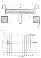
- Fig.2 shows a schematic cross section through an arc source with a magnetic system, as it is for the targets Fig. 1 MAG Z and MAG V was used.
- a circumferential confinement ring 3 for limiting the spark is arranged on the target surface.
- a usually also circulating counter electrode, usually an anode is not shown here.
- the power supply 5 which may also include adewasserzu- and discharges not shown here.
- an inner permanent magnet ring 6 is located in the central rear region.
- Both magnet rings are axially magnetized opposite polarity, so that a part of the field lines, which emerge from the top of the outer permanent magnet ring 7 in the top of the inner permanent magnet ring 6 re-enter, while the field line course on the back with respect to the ring plane is substantially mirror-inverted.
- different strong magnets in addition to a coil as in Figure 5 or other arrangements are used.
- FIG 3 the local field strength of a magnet system is shown, as it adjusts to the surface of an Arctarget when using a built-standard magnet system "MAG Z" Balzers.
- the figure shows the Field strength curve of the vertical component B z and the radial B r component on a target half.
- B z has a maximum in the middle (O coordinate) and at the edge (75 mm) and passes through the zero line at approx. 45 mm.
- the 45 ° point defined by the intersection of the absolute components, ie the point or circumference on which the field lines arrive at an angle of 45 ° on the target surface, is approximately 27 and 59 mm.
- the radial component B r is greater than B z and passes through a maximum.
- B r does not change direction on the respective target half and cuts the zero line at the zero point and at the target edge.
- the intermediate region in which relatively high radial acceleration forces act on the spark passing through the target, is a preferred residence region, which is due to the corresponding erosion characteristic in FIG Fig. 1 "MAG Z" is also clearly visible.
- it is also due to the very small radial component in the central target area and the associated slow movement of individual sparks, leaving the preferred residence area, by overheating and explosion explosive evaporation in an increased removal, damage to the surface and increased Droplet Struktur.
- Figure 4 shows the corresponding field strength characteristic of, for the evaporation of in Fig.1 shown targets with magnet system "MAG V".
- the magnetic field differs by one opposite Figure 3 in the Average about 50% higher field strength for both components. Accordingly one sees on the target surface in Fig. 1 "MAG V" also in the outdoor area an increased removal. Also in this case the surface is heavily damaged.
- FIG. 5 a schematic cross section through an arc source with a magnet system "MAG S" 8, as it is for the evaporation of the surfaces of the target in Fig. 1 "MAG S" was used according to the inventive method.
- an electromagnetic coil 8 mounted behind the target 1 in the region of the projection of the target periphery is used.
- Magnetic systems that are composed of one or more electric coils, with little or no strong support by strong permanent magnets, are advantageous here.
- the coil current can be changed analogously to the change in the surface state of the target.
- the magnetic field can be downshifted in parallel to the nitrogen ramp while the oxygen flux is continuously increased. In this way, even without pulse operation of the arc source any continuous transitions can be made with materials that require magnetic field support for the evaporation of the conductive surface.
- FIG 6 shows the field strength that results in the operation of such a magnet system with low currents.
- a standard magnet system "MAG S” (432 turns) from Balzers was operated with a current of 1A.
- the B z component is set less than 50 Gauss, in particular less than or equal to 30 Gauss.
- an additional system which can be displaced perpendicularly to the target plane would be advantageous, for example, analogously to a magnetic field distribution which is favorable for the production of certain metal nitrides, with larger magnetic fields at the target top side 3 and 4 manufacture.
- the treatment chamber is pumped to a pressure of about 10 -4 mbar.
- a low-voltage arc (NVB) plasma which is assisted by radiant heaters, is ignited between a cathode chamber with hot cathode separated by an aperture and the anodically connected workpieces in an argon-hydrogen atmosphere.
- NVB low-voltage arc
- the substrates were preferably switched as an anode for the low-voltage arc and preferably additionally pulsed in unipolar or bipolar.
- the etching is started.
- the low-voltage arc is operated between the filament and the auxiliary anode.
- a DC, a pulsed DC or an AC powered MF or RF supply between workpieces and ground can be switched.
- the workpieces were subjected to a negative bias voltage.
- etching parameters were set: argon flow 60 sccm process pressure 2.4x10 -3 mbar Discharge current NVB 150 A substrate temperature about 500 ° C process time 45 min bias 200 - 250 V
- NVB low-voltage arc discharge
- the substrate is coated with an AlCrO layer and a TiAlN intermediate layer. All coating processes can be supported by the plasma of the low-voltage arc, if required, due to increased ionization.
- the AlCr arc sources are switched on with a DC source current of 200 A, whereby the positive pole of the DC source is connected to the anode ring of the source and ground.
- a DC substrate bias of -40 V is applied to the substrates during this step.
- the oxygen inlet is started, and the oxygen inlet is controlled from 50 to 1000 sccm within 10 minutes.
- N 2 is regulated back to approximately 100 sccm.
- the two TiAl targets are switched off.
- the intermediate layer and the graded transition to the functional layer are completed.
- alumina is an insulating layer, either a pulsed or an AC bias supply is used.
Landscapes
- Chemical & Material Sciences (AREA)
- Engineering & Computer Science (AREA)
- Physics & Mathematics (AREA)
- Plasma & Fusion (AREA)
- Analytical Chemistry (AREA)
- Chemical Kinetics & Catalysis (AREA)
- Materials Engineering (AREA)
- Mechanical Engineering (AREA)
- Metallurgy (AREA)
- Organic Chemistry (AREA)
- Physical Vapour Deposition (AREA)
- Superconductors And Manufacturing Methods Therefor (AREA)
Applications Claiming Priority (2)
| Application Number | Priority Date | Filing Date | Title |
|---|---|---|---|
| CH11662006 | 2006-07-19 | ||
| EP07787450.1A EP2041331B1 (fr) | 2006-07-19 | 2007-07-12 | Procédé pour le dépôt de couches électriquement isolantes |
Related Parent Applications (2)
| Application Number | Title | Priority Date | Filing Date |
|---|---|---|---|
| EP07787450.1A Division-Into EP2041331B1 (fr) | 2006-07-19 | 2007-07-12 | Procédé pour le dépôt de couches électriquement isolantes |
| EP07787450.1 Division | 2007-07-12 |
Publications (2)
| Publication Number | Publication Date |
|---|---|
| EP2599891A2 true EP2599891A2 (fr) | 2013-06-05 |
| EP2599891A3 EP2599891A3 (fr) | 2013-08-07 |
Family
ID=37174179
Family Applications (2)
| Application Number | Title | Priority Date | Filing Date |
|---|---|---|---|
| EP13156872.7A Withdrawn EP2599891A3 (fr) | 2006-07-19 | 2007-07-12 | Procédé de depôt de couches de matériau isolant. |
| EP07787450.1A Active EP2041331B1 (fr) | 2006-07-19 | 2007-07-12 | Procédé pour le dépôt de couches électriquement isolantes |
Family Applications After (1)
| Application Number | Title | Priority Date | Filing Date |
|---|---|---|---|
| EP07787450.1A Active EP2041331B1 (fr) | 2006-07-19 | 2007-07-12 | Procédé pour le dépôt de couches électriquement isolantes |
Country Status (20)
| Country | Link |
|---|---|
| US (1) | US8197648B2 (fr) |
| EP (2) | EP2599891A3 (fr) |
| JP (1) | JP5306198B2 (fr) |
| KR (1) | KR101361234B1 (fr) |
| CN (1) | CN101490305B (fr) |
| AU (1) | AU2007276186B2 (fr) |
| BR (1) | BRPI0714437B1 (fr) |
| CA (1) | CA2657726C (fr) |
| ES (1) | ES2527877T3 (fr) |
| HK (1) | HK1129910A1 (fr) |
| IL (1) | IL196488A (fr) |
| MX (1) | MX2009000593A (fr) |
| MY (1) | MY167043A (fr) |
| NZ (1) | NZ573694A (fr) |
| PT (1) | PT2041331E (fr) |
| RU (1) | RU2461664C2 (fr) |
| TW (1) | TWI411696B (fr) |
| UA (1) | UA95809C2 (fr) |
| WO (1) | WO2008009619A1 (fr) |
| ZA (1) | ZA200900374B (fr) |
Families Citing this family (13)
| Publication number | Priority date | Publication date | Assignee | Title |
|---|---|---|---|---|
| PL2166128T3 (pl) * | 2008-09-19 | 2012-05-31 | Oerlikon Trading Ag | Sposób wytwarzania powłok z tlenków metali przez naparowywanie łukowe |
| DE102009022982A1 (de) * | 2009-05-28 | 2010-12-02 | Oerlikon Trading Ag, Trübbach | Verfahren zum Aufbringen eines Hochtemperaturschmiermittels |
| WO2011009573A1 (fr) | 2009-07-22 | 2011-01-27 | Oerlikon Trading Ag, Trübach | Procédé de production de revêtements avec une seule cible composite |
| EP2369031B1 (fr) | 2010-03-18 | 2016-05-04 | Oerlikon Trading AG, Trübbach | Revêtement à base de nial2o4 dans une structure de spinelle |
| DE102010042828A1 (de) * | 2010-10-22 | 2012-04-26 | Walter Ag | Target für Lichtbogenverfahren |
| PL2761058T3 (pl) * | 2011-09-30 | 2020-03-31 | Oerlikon Surface Solutions Ag, Pfäffikon | Powłoka z azotku glinu tytanu o morfologii przystosowanej do zwiększonej odporności na zużycie w operacjach obróbki skrawaniem oraz sposób jej |
| MX369729B (es) | 2013-04-30 | 2019-11-20 | Nippon Itf Inc | Fuente de evaporación por arco. |
| CN108368618B (zh) * | 2015-12-22 | 2020-12-11 | 山特维克知识产权股份有限公司 | 制造pvd层的方法和涂覆的切削工具 |
| MY189225A (en) * | 2016-04-22 | 2022-01-31 | Oerlikon Surface Solutions Ag Pfaffikon | Ticn having reduced growth defects by means of hipims |
| EP3556901B1 (fr) | 2018-04-20 | 2021-03-31 | Plansee Composite Materials Gmbh | Source d'arc sous vide |
| DE102018112335A1 (de) * | 2018-05-23 | 2019-11-28 | Hartmetall-Werkzeugfabrik Paul Horn Gmbh | Magnetronsputtervorrichtung |
| RU2761900C1 (ru) * | 2021-02-08 | 2021-12-13 | Федеральное государственное бюджетное учреждение науки Институт радиотехники и электроники им. В.А. Котельникова Российской академии наук | Магнетронное распылительное устройство |
| CN114324369B (zh) * | 2022-03-11 | 2022-06-07 | 北京新研创能科技有限公司 | 双极板表面划痕检测系统及方法 |
Citations (4)
| Publication number | Priority date | Publication date | Assignee | Title |
|---|---|---|---|---|
| EP0285745B1 (fr) | 1987-03-06 | 1993-05-26 | Balzers Aktiengesellschaft | Procédé et dispositifs de déposition sous vide utilisant une décharge électrique |
| DE4223592A1 (de) | 1992-06-24 | 1994-01-05 | Leybold Ag | Lichtbogen-Verdampfungsvorrichtung |
| US6334405B1 (en) | 1999-01-14 | 2002-01-01 | Kobe Steel, Ltd. | Vacuum arc evaporation source and vacuum arc vapor deposition apparatus |
| WO2004057642A2 (fr) | 2002-12-19 | 2004-07-08 | Unaxis Balzers Aktiengesellschaft | Source d'arc sous vide comprenant un dispositif de production de champ magnetique |
Family Cites Families (16)
| Publication number | Priority date | Publication date | Assignee | Title |
|---|---|---|---|---|
| US3625848A (en) * | 1968-12-26 | 1971-12-07 | Alvin A Snaper | Arc deposition process and apparatus |
| JPS63501646A (ja) * | 1985-09-30 | 1988-06-23 | ユニオン カ−バイド コ−ポレ−シヨン | 真空室内でコ−テイングをア−ク蒸着する為の装置及び方法 |
| JPH0699799B2 (ja) * | 1988-03-18 | 1994-12-07 | 株式会社神戸製鋼所 | 真空蒸着方法 |
| JP2718731B2 (ja) * | 1988-12-21 | 1998-02-25 | 株式会社神戸製鋼所 | 真空アーク蒸着装置及び真空アーク蒸着方法 |
| RU2176681C2 (ru) * | 1989-11-22 | 2001-12-10 | Волков Валерий Венедиктович | Способ получения покрытий в вакууме, устройство для получения покрытий в вакууме, способ изготовления устройства для получения покрытий в вакууме |
| DE69416963T2 (de) * | 1993-12-17 | 1999-09-16 | Kabushiki Kaisha Kobe Seiko Sho (Kobe Steel, Ltd.) | Vorrichtung zur Bogenbeschichtung im Vakuum |
| JP3243357B2 (ja) * | 1993-12-21 | 2002-01-07 | 株式会社神戸製鋼所 | 真空アーク蒸着装置 |
| CH688863A5 (de) * | 1994-06-24 | 1998-04-30 | Balzers Hochvakuum | Verfahren zum Beschichten mindestens eines Werkstueckes und Anlage hierfuer. |
| JP3060876B2 (ja) * | 1995-02-15 | 2000-07-10 | 日新電機株式会社 | 金属イオン注入装置 |
| JP2878997B2 (ja) * | 1995-09-26 | 1999-04-05 | 株式会社神戸製鋼所 | 真空蒸着装置 |
| CA2256847A1 (fr) * | 1998-12-22 | 2000-06-22 | Munther Kandah | Source ionique exempte de particules pour arc cathodique au carbone |
| JP3104701B1 (ja) * | 1999-08-18 | 2000-10-30 | 日新電機株式会社 | アーク式蒸発源 |
| JP2002069664A (ja) * | 2000-08-28 | 2002-03-08 | Hiroshi Takigawa | プラズマ加工方法及びプラズマ加工装置 |
| JP2002254207A (ja) * | 2001-02-23 | 2002-09-10 | Mmc Kobelco Tool Kk | 切粉に対する表面潤滑性にすぐれた表面被覆超硬合金製切削工具 |
| CA2523882C (fr) * | 2003-04-28 | 2014-02-11 | Unaxis Balzers Ag | Piece a usiner comportant une couche de matiere dure contenant de l'alcr et procede de fabrication associe |
| US7857948B2 (en) * | 2006-07-19 | 2010-12-28 | Oerlikon Trading Ag, Trubbach | Method for manufacturing poorly conductive layers |
-
2007
- 2007-07-11 TW TW096125180A patent/TWI411696B/zh not_active IP Right Cessation
- 2007-07-12 WO PCT/EP2007/057179 patent/WO2008009619A1/fr active Application Filing
- 2007-07-12 CN CN200780027414.1A patent/CN101490305B/zh not_active Expired - Fee Related
- 2007-07-12 BR BRPI0714437-7A patent/BRPI0714437B1/pt not_active IP Right Cessation
- 2007-07-12 CA CA2657726A patent/CA2657726C/fr not_active Expired - Fee Related
- 2007-07-12 US US12/374,319 patent/US8197648B2/en not_active Expired - Fee Related
- 2007-07-12 PT PT77874501T patent/PT2041331E/pt unknown
- 2007-07-12 RU RU2009105668/02A patent/RU2461664C2/ru not_active IP Right Cessation
- 2007-07-12 MY MYPI20090219A patent/MY167043A/en unknown
- 2007-07-12 EP EP13156872.7A patent/EP2599891A3/fr not_active Withdrawn
- 2007-07-12 MX MX2009000593A patent/MX2009000593A/es active IP Right Grant
- 2007-07-12 EP EP07787450.1A patent/EP2041331B1/fr active Active
- 2007-07-12 KR KR1020097000856A patent/KR101361234B1/ko active IP Right Grant
- 2007-07-12 AU AU2007276186A patent/AU2007276186B2/en not_active Ceased
- 2007-07-12 ES ES07787450.1T patent/ES2527877T3/es active Active
- 2007-07-12 NZ NZ573694A patent/NZ573694A/en not_active IP Right Cessation
- 2007-07-12 UA UAA200901382A patent/UA95809C2/ru unknown
- 2007-07-12 ZA ZA200900374A patent/ZA200900374B/xx unknown
- 2007-07-12 JP JP2009519945A patent/JP5306198B2/ja not_active Expired - Fee Related
-
2009
- 2009-01-13 IL IL196488A patent/IL196488A/en active IP Right Grant
- 2009-08-20 HK HK09107663A patent/HK1129910A1/xx not_active IP Right Cessation
Patent Citations (4)
| Publication number | Priority date | Publication date | Assignee | Title |
|---|---|---|---|---|
| EP0285745B1 (fr) | 1987-03-06 | 1993-05-26 | Balzers Aktiengesellschaft | Procédé et dispositifs de déposition sous vide utilisant une décharge électrique |
| DE4223592A1 (de) | 1992-06-24 | 1994-01-05 | Leybold Ag | Lichtbogen-Verdampfungsvorrichtung |
| US6334405B1 (en) | 1999-01-14 | 2002-01-01 | Kobe Steel, Ltd. | Vacuum arc evaporation source and vacuum arc vapor deposition apparatus |
| WO2004057642A2 (fr) | 2002-12-19 | 2004-07-08 | Unaxis Balzers Aktiengesellschaft | Source d'arc sous vide comprenant un dispositif de production de champ magnetique |
Also Published As
| Publication number | Publication date |
|---|---|
| JP2009543951A (ja) | 2009-12-10 |
| EP2041331A1 (fr) | 2009-04-01 |
| AU2007276186A1 (en) | 2008-01-24 |
| PT2041331E (pt) | 2015-01-14 |
| CN101490305B (zh) | 2014-02-12 |
| NZ573694A (en) | 2012-02-24 |
| CA2657726A1 (fr) | 2008-01-24 |
| MY167043A (en) | 2018-08-02 |
| RU2461664C2 (ru) | 2012-09-20 |
| JP5306198B2 (ja) | 2013-10-02 |
| BRPI0714437A2 (pt) | 2013-03-12 |
| US8197648B2 (en) | 2012-06-12 |
| ZA200900374B (en) | 2010-04-28 |
| WO2008009619A1 (fr) | 2008-01-24 |
| KR20090031904A (ko) | 2009-03-30 |
| MX2009000593A (es) | 2009-04-07 |
| CN101490305A (zh) | 2009-07-22 |
| RU2009105668A (ru) | 2010-08-27 |
| CA2657726C (fr) | 2015-05-26 |
| EP2041331B1 (fr) | 2014-10-22 |
| ES2527877T3 (es) | 2015-02-02 |
| HK1129910A1 (en) | 2009-12-11 |
| EP2599891A3 (fr) | 2013-08-07 |
| IL196488A (en) | 2014-11-30 |
| WO2008009619A9 (fr) | 2009-04-16 |
| IL196488A0 (en) | 2009-09-22 |
| TWI411696B (zh) | 2013-10-11 |
| BRPI0714437B1 (pt) | 2018-06-05 |
| UA95809C2 (ru) | 2011-09-12 |
| TW200806803A (en) | 2008-02-01 |
| KR101361234B1 (ko) | 2014-02-11 |
| US20090166188A1 (en) | 2009-07-02 |
| AU2007276186B2 (en) | 2012-03-01 |
Similar Documents
| Publication | Publication Date | Title |
|---|---|---|
| EP2041331B1 (fr) | Procédé pour le dépôt de couches électriquement isolantes | |
| EP1869690B2 (fr) | Procédé d'utilisation d'une source d'arc pulsée | |
| EP2355126B1 (fr) | Couche dure | |
| EP2720249B1 (fr) | Chambre de vaporisation d'arcs électriques dotée d'une source de vaporisation d'arcs électriques sous vide | |
| EP0285745B1 (fr) | Procédé et dispositifs de déposition sous vide utilisant une décharge électrique | |
| EP2236641B1 (fr) | Procédé de traitement préalable de substrats pour le procédé de PVD | |
| EP2208216B1 (fr) | Procédé de fonctionnement d'une source d'arc et procédé de séparation des couches électriquement isolantes | |
| EP2653583B1 (fr) | Procédé de revêtement destiné à la séparation d'un système de couche sur un substrat | |
| EP2018653A2 (fr) | Source d'arc et ensemble aimants | |
| EP0886880A1 (fr) | Procede et dispositif pour le revetement de pieces | |
| EP2394288A1 (fr) | Configuration d'aimant modifiable pour sources de vaporisation à arc | |
| EP2439763B1 (fr) | Dispositif de magnétron et procédé de fonctionnement pulsé d'un dispositif à magnétron | |
| EP0734459B1 (fr) | Procede et dispositif de metallisation en phase vapeur activee au plasma | |
| EP2175044A1 (fr) | Procédé de revêtement PVD, dispositif d'exécution du procédé et substances revêtues selon ce procédé | |
| DE102016116762A1 (de) | Verfahren zum Abscheiden einer Schicht mittels einer Magnetronsputtereinrichtung | |
| WO2020126531A1 (fr) | Ensemble aimant conçu pour une source de plasma pour réaliser des traitement au plasma | |
| CH695807A5 (de) | Quelle für Vakuumbehandlungsprozess. | |
| EP0791226B1 (fr) | Dispositif pour le recouvrement de substrats au moyen d'un materiau en phase vapeur, sous pression reduite ou sous vide | |
| EP3900011B1 (fr) | Ensemble aimant conçu pour une source de plasma pour réaliser des traitement au plasma | |
| DE69808267T2 (de) | Verfahren und vorrichtung für pvd beschichtung | |
| EP1473382A1 (fr) | Procédé et dispositif de déposition d'une couche activée par plasma par pulvérisation magnétron | |
| DE102020124032A1 (de) | Beschichtungsvorrichtung und Beschichtungsverfahren mit unterteilten Pulsen |
Legal Events
| Date | Code | Title | Description |
|---|---|---|---|
| PUAI | Public reference made under article 153(3) epc to a published international application that has entered the european phase |
Free format text: ORIGINAL CODE: 0009012 |
|
| AC | Divisional application: reference to earlier application |
Ref document number: 2041331 Country of ref document: EP Kind code of ref document: P |
|
| AK | Designated contracting states |
Kind code of ref document: A2 Designated state(s): AT BE BG CH CY CZ DE DK EE ES FI FR GB GR HU IE IS IT LI LT LU LV MC MT NL PL PT RO SE SI SK TR |
|
| PUAL | Search report despatched |
Free format text: ORIGINAL CODE: 0009013 |
|
| AK | Designated contracting states |
Kind code of ref document: A3 Designated state(s): AT BE BG CH CY CZ DE DK EE ES FI FR GB GR HU IE IS IT LI LT LU LV MC MT NL PL PT RO SE SI SK TR |
|
| RIC1 | Information provided on ipc code assigned before grant |
Ipc: H01J 37/34 20060101ALI20130628BHEP Ipc: C23C 14/08 20060101ALI20130628BHEP Ipc: H01J 37/32 20060101ALI20130628BHEP Ipc: C23C 14/32 20060101AFI20130628BHEP |
|
| 17P | Request for examination filed |
Effective date: 20140207 |
|
| RBV | Designated contracting states (corrected) |
Designated state(s): AT BE BG CH CY CZ DE DK EE ES FI FR GB GR HU IE IS IT LI LT LU LV MC MT NL PL PT RO SE SI SK TR |
|
| STAA | Information on the status of an ep patent application or granted ep patent |
Free format text: STATUS: THE APPLICATION IS DEEMED TO BE WITHDRAWN |
|
| 18D | Application deemed to be withdrawn |
Effective date: 20170201 |