EP2582886B1 - Vorrichtungen, systeme und verfahren zur infrastrukturüberwachung - Google Patents
Vorrichtungen, systeme und verfahren zur infrastrukturüberwachung Download PDFInfo
- Publication number
- EP2582886B1 EP2582886B1 EP11796120.1A EP11796120A EP2582886B1 EP 2582886 B1 EP2582886 B1 EP 2582886B1 EP 11796120 A EP11796120 A EP 11796120A EP 2582886 B1 EP2582886 B1 EP 2582886B1
- Authority
- EP
- European Patent Office
- Prior art keywords
- nozzle cap
- processor
- operations center
- water
- sensor
- Prior art date
- Legal status (The legal status is an assumption and is not a legal conclusion. Google has not performed a legal analysis and makes no representation as to the accuracy of the status listed.)
- Active
Links
Images


Classifications
-
- A—HUMAN NECESSITIES
- A62—LIFE-SAVING; FIRE-FIGHTING
- A62C—FIRE-FIGHTING
- A62C37/00—Control of fire-fighting equipment
- A62C37/50—Testing or indicating devices for determining the state of readiness of the equipment
-
- A—HUMAN NECESSITIES
- A62—LIFE-SAVING; FIRE-FIGHTING
- A62C—FIRE-FIGHTING
- A62C35/00—Permanently-installed equipment
- A62C35/20—Hydrants, e.g. wall-hoses, wall units, plug-in cabinets
-
- E—FIXED CONSTRUCTIONS
- E03—WATER SUPPLY; SEWERAGE
- E03B—INSTALLATIONS OR METHODS FOR OBTAINING, COLLECTING, OR DISTRIBUTING WATER
- E03B9/00—Methods or installations for drawing-off water
- E03B9/02—Hydrants; Arrangements of valves therein; Keys for hydrants
-
- E—FIXED CONSTRUCTIONS
- E03—WATER SUPPLY; SEWERAGE
- E03B—INSTALLATIONS OR METHODS FOR OBTAINING, COLLECTING, OR DISTRIBUTING WATER
- E03B9/00—Methods or installations for drawing-off water
- E03B9/02—Hydrants; Arrangements of valves therein; Keys for hydrants
- E03B9/04—Column hydrants
- E03B9/06—Covers
-
- F—MECHANICAL ENGINEERING; LIGHTING; HEATING; WEAPONS; BLASTING
- F16—ENGINEERING ELEMENTS AND UNITS; GENERAL MEASURES FOR PRODUCING AND MAINTAINING EFFECTIVE FUNCTIONING OF MACHINES OR INSTALLATIONS; THERMAL INSULATION IN GENERAL
- F16K—VALVES; TAPS; COCKS; ACTUATING-FLOATS; DEVICES FOR VENTING OR AERATING
- F16K27/00—Construction of housing; Use of materials therefor
- F16K27/006—Construction of housing; Use of materials therefor of hydrants
-
- F—MECHANICAL ENGINEERING; LIGHTING; HEATING; WEAPONS; BLASTING
- F17—STORING OR DISTRIBUTING GASES OR LIQUIDS
- F17D—PIPE-LINE SYSTEMS; PIPE-LINES
- F17D1/00—Pipe-line systems
- F17D1/02—Pipe-line systems for gases or vapours
- F17D1/04—Pipe-line systems for gases or vapours for distribution of gas
-
- F—MECHANICAL ENGINEERING; LIGHTING; HEATING; WEAPONS; BLASTING
- F17—STORING OR DISTRIBUTING GASES OR LIQUIDS
- F17D—PIPE-LINE SYSTEMS; PIPE-LINES
- F17D5/00—Protection or supervision of installations
-
- F—MECHANICAL ENGINEERING; LIGHTING; HEATING; WEAPONS; BLASTING
- F17—STORING OR DISTRIBUTING GASES OR LIQUIDS
- F17D—PIPE-LINE SYSTEMS; PIPE-LINES
- F17D5/00—Protection or supervision of installations
- F17D5/02—Preventing, monitoring, or locating loss
-
- G—PHYSICS
- G01—MEASURING; TESTING
- G01D—MEASURING NOT SPECIALLY ADAPTED FOR A SPECIFIC VARIABLE; ARRANGEMENTS FOR MEASURING TWO OR MORE VARIABLES NOT COVERED IN A SINGLE OTHER SUBCLASS; TARIFF METERING APPARATUS; MEASURING OR TESTING NOT OTHERWISE PROVIDED FOR
- G01D4/00—Tariff metering apparatus
- G01D4/002—Remote reading of utility meters
- G01D4/004—Remote reading of utility meters to a fixed location
-
- G—PHYSICS
- G01—MEASURING; TESTING
- G01F—MEASURING VOLUME, VOLUME FLOW, MASS FLOW OR LIQUID LEVEL; METERING BY VOLUME
- G01F1/00—Measuring the volume flow or mass flow of fluid or fluent solid material wherein the fluid passes through a meter in a continuous flow
- G01F1/05—Measuring the volume flow or mass flow of fluid or fluent solid material wherein the fluid passes through a meter in a continuous flow by using mechanical effects
- G01F1/34—Measuring the volume flow or mass flow of fluid or fluent solid material wherein the fluid passes through a meter in a continuous flow by using mechanical effects by measuring pressure or differential pressure
- G01F1/36—Measuring the volume flow or mass flow of fluid or fluent solid material wherein the fluid passes through a meter in a continuous flow by using mechanical effects by measuring pressure or differential pressure the pressure or differential pressure being created by the use of flow constriction
- G01F1/40—Details of construction of the flow constriction devices
- G01F1/46—Pitot tubes
-
- G—PHYSICS
- G01—MEASURING; TESTING
- G01M—TESTING STATIC OR DYNAMIC BALANCE OF MACHINES OR STRUCTURES; TESTING OF STRUCTURES OR APPARATUS, NOT OTHERWISE PROVIDED FOR
- G01M3/00—Investigating fluid-tightness of structures
-
- H—ELECTRICITY
- H04—ELECTRIC COMMUNICATION TECHNIQUE
- H04B—TRANSMISSION
- H04B1/00—Details of transmission systems, not covered by a single one of groups H04B3/00 - H04B13/00; Details of transmission systems not characterised by the medium used for transmission
- H04B1/02—Transmitters
- H04B1/03—Constructional details, e.g. casings, housings
-
- G—PHYSICS
- G01—MEASURING; TESTING
- G01D—MEASURING NOT SPECIALLY ADAPTED FOR A SPECIFIC VARIABLE; ARRANGEMENTS FOR MEASURING TWO OR MORE VARIABLES NOT COVERED IN A SINGLE OTHER SUBCLASS; TARIFF METERING APPARATUS; MEASURING OR TESTING NOT OTHERWISE PROVIDED FOR
- G01D2204/00—Indexing scheme relating to details of tariff-metering apparatus
- G01D2204/10—Analysing; Displaying
- G01D2204/12—Determination or prediction of behaviour, e.g. likely power consumption or unusual usage patterns
-
- Y—GENERAL TAGGING OF NEW TECHNOLOGICAL DEVELOPMENTS; GENERAL TAGGING OF CROSS-SECTIONAL TECHNOLOGIES SPANNING OVER SEVERAL SECTIONS OF THE IPC; TECHNICAL SUBJECTS COVERED BY FORMER USPC CROSS-REFERENCE ART COLLECTIONS [XRACs] AND DIGESTS
- Y02—TECHNOLOGIES OR APPLICATIONS FOR MITIGATION OR ADAPTATION AGAINST CLIMATE CHANGE
- Y02B—CLIMATE CHANGE MITIGATION TECHNOLOGIES RELATED TO BUILDINGS, e.g. HOUSING, HOUSE APPLIANCES OR RELATED END-USER APPLICATIONS
- Y02B90/00—Enabling technologies or technologies with a potential or indirect contribution to GHG emissions mitigation
- Y02B90/20—Smart grids as enabling technology in buildings sector
-
- Y—GENERAL TAGGING OF NEW TECHNOLOGICAL DEVELOPMENTS; GENERAL TAGGING OF CROSS-SECTIONAL TECHNOLOGIES SPANNING OVER SEVERAL SECTIONS OF THE IPC; TECHNICAL SUBJECTS COVERED BY FORMER USPC CROSS-REFERENCE ART COLLECTIONS [XRACs] AND DIGESTS
- Y02—TECHNOLOGIES OR APPLICATIONS FOR MITIGATION OR ADAPTATION AGAINST CLIMATE CHANGE
- Y02E—REDUCTION OF GREENHOUSE GAS [GHG] EMISSIONS, RELATED TO ENERGY GENERATION, TRANSMISSION OR DISTRIBUTION
- Y02E60/00—Enabling technologies; Technologies with a potential or indirect contribution to GHG emissions mitigation
- Y02E60/30—Hydrogen technology
- Y02E60/34—Hydrogen distribution
-
- Y—GENERAL TAGGING OF NEW TECHNOLOGICAL DEVELOPMENTS; GENERAL TAGGING OF CROSS-SECTIONAL TECHNOLOGIES SPANNING OVER SEVERAL SECTIONS OF THE IPC; TECHNICAL SUBJECTS COVERED BY FORMER USPC CROSS-REFERENCE ART COLLECTIONS [XRACs] AND DIGESTS
- Y04—INFORMATION OR COMMUNICATION TECHNOLOGIES HAVING AN IMPACT ON OTHER TECHNOLOGY AREAS
- Y04S—SYSTEMS INTEGRATING TECHNOLOGIES RELATED TO POWER NETWORK OPERATION, COMMUNICATION OR INFORMATION TECHNOLOGIES FOR IMPROVING THE ELECTRICAL POWER GENERATION, TRANSMISSION, DISTRIBUTION, MANAGEMENT OR USAGE, i.e. SMART GRIDS
- Y04S20/00—Management or operation of end-user stationary applications or the last stages of power distribution; Controlling, monitoring or operating thereof
- Y04S20/30—Smart metering, e.g. specially adapted for remote reading
-
- Y—GENERAL TAGGING OF NEW TECHNOLOGICAL DEVELOPMENTS; GENERAL TAGGING OF CROSS-SECTIONAL TECHNOLOGIES SPANNING OVER SEVERAL SECTIONS OF THE IPC; TECHNICAL SUBJECTS COVERED BY FORMER USPC CROSS-REFERENCE ART COLLECTIONS [XRACs] AND DIGESTS
- Y10—TECHNICAL SUBJECTS COVERED BY FORMER USPC
- Y10T—TECHNICAL SUBJECTS COVERED BY FORMER US CLASSIFICATION
- Y10T137/00—Fluid handling
- Y10T137/5327—Hydrant type
- Y10T137/5456—With casing
- Y10T137/5468—Cap, cover or hood
-
- Y—GENERAL TAGGING OF NEW TECHNOLOGICAL DEVELOPMENTS; GENERAL TAGGING OF CROSS-SECTIONAL TECHNOLOGIES SPANNING OVER SEVERAL SECTIONS OF THE IPC; TECHNICAL SUBJECTS COVERED BY FORMER USPC CROSS-REFERENCE ART COLLECTIONS [XRACs] AND DIGESTS
- Y10—TECHNICAL SUBJECTS COVERED BY FORMER USPC
- Y10T—TECHNICAL SUBJECTS COVERED BY FORMER US CLASSIFICATION
- Y10T137/00—Fluid handling
- Y10T137/5327—Hydrant type
- Y10T137/5485—With valve at outlet
-
- Y—GENERAL TAGGING OF NEW TECHNOLOGICAL DEVELOPMENTS; GENERAL TAGGING OF CROSS-SECTIONAL TECHNOLOGIES SPANNING OVER SEVERAL SECTIONS OF THE IPC; TECHNICAL SUBJECTS COVERED BY FORMER USPC CROSS-REFERENCE ART COLLECTIONS [XRACs] AND DIGESTS
- Y10—TECHNICAL SUBJECTS COVERED BY FORMER USPC
- Y10T—TECHNICAL SUBJECTS COVERED BY FORMER US CLASSIFICATION
- Y10T137/00—Fluid handling
- Y10T137/6851—With casing, support, protector or static constructional installations
- Y10T137/7043—Guards and shields
-
- Y—GENERAL TAGGING OF NEW TECHNOLOGICAL DEVELOPMENTS; GENERAL TAGGING OF CROSS-SECTIONAL TECHNOLOGIES SPANNING OVER SEVERAL SECTIONS OF THE IPC; TECHNICAL SUBJECTS COVERED BY FORMER USPC CROSS-REFERENCE ART COLLECTIONS [XRACs] AND DIGESTS
- Y10—TECHNICAL SUBJECTS COVERED BY FORMER USPC
- Y10T—TECHNICAL SUBJECTS COVERED BY FORMER US CLASSIFICATION
- Y10T137/00—Fluid handling
- Y10T137/8158—With indicator, register, recorder, alarm or inspection means
Definitions
- the disclosure is directed to a nozzle cap assembly according to the invention and to systems, and methods related to monitoring and controlling an infrastructure such as, but not limited to, the supply and use of commercial, industrial or residential water, gas and/or electric utilities, and, in particular, to devices, methods, and systems for monitoring and controlling a municipality and alerting a user to potential faults and actions required.
- an infrastructure such as, but not limited to, the supply and use of commercial, industrial or residential water, gas and/or electric utilities, and, in particular, to devices, methods, and systems for monitoring and controlling a municipality and alerting a user to potential faults and actions required.
- Municipalities administer and/or outsource numerous utility and safety systems within each municipality.
- Such systems are usually complex infrastructures and include but are not limited to water distribution, gas distribution, electricity distribution, waste management, traffic control, fire departments, police departments, and emergency response departments.
- Each of these systems needs to be monitored for use (authorized or unauthorized), faults, tampering, events, interruptions or blockages, leaks, contamination, and/or other issues.
- a leak in a water main may cost a water company a significant amount of money in lost water, energy usage, and chemical treatment, particularly if the leak is not discovered for a relatively long period of time.
- a leak can lead to underground structural erosion. Interference with a system may go unnoticed unless it is reported to a central location.
- Another problem and disadvantage associated with current systems is the lack of property rights sufficient to maintain a network of monitors and device controllers capable of creating a transmission infrastructure that can adapt to multiple monitors and controllers and form an information network for providing information about the system to the utility monitoring the network.
- some networks require that new poles or towers be erected for placement of the communication devices.
- Municipalities may have to rent space on a utility company's poles for placement of such devices.
- an issue in one system may cause an issue in another system.
- a fire reported to the fire department may require the gas company to turn off gas flow to the vicinity of the fire and may require the water company to redirect water or additional water pressure to the vicinity.
- many current systems are not interoperable.
- US-A-2003/107485 discloses a nozzle cap assembly according to the preamble of claim 1 and describes a detection and signaling apparatus mountable in a fire hydrant to detect a parameter, such as unauthorized movement of a discharge nozzle cap relative to the fire hydrant.
- a fire hydrant may comprise the nozzle cap assembly including a nozzle cap.
- the nozzle cap may comprise a nut to permit the application of force to firmly attach the nozzle cap (600) to or to remove it from an outlet nozzle of a fire hydrant, the nut having a through hole, a facetted outer surface, and an outer end; and the communications device coupled to the nozzle cap, wherein the communications device is a component of an infrastructure monitoring system, and wherein the nozzle cap defines the interior cavity, wherein the communications device is located inside the interior cavity, and wherein the nozzle cap includes the enclosure, the enclosure comprising a wide portion for receiving the communications device and a narrow portion with an external threading, the cover to seal the enclosure, and the antenna cover with an antenna cover cavity for receiving an antenna of the communications device, wherein the communications device is positioned within the wide portion of the enclosure and the cover, and wherein the nozzle cap has a first internal threading for connecting the nozzle cap with a fire
- the disclosures herein provide exemplary embodiments of the nozzle cap assembly of the invention and examples of related systems, methods, and devices.
- Features may be embodied in various and alternative forms. Therefore, there is no intent that specific structural and functional details should be limiting, but rather the intention is that they provide a basis for the claims and as a representative basis for teaching one skilled in the art to variously employ the present disclosure.
- a problem in the art capable of being solved by the embodiments disclosed is monitoring and maintaining an infrastructure. It has been discovered that monitoring devices with one or two way communication abilities can be used to detect faults in the municipality's systems and provide on-demand, real time, or near real time device status, maintenance, and control over the systems.
- a network of monitoring devices is capable of providing a system administrator with a full picture of the current state of the system.
- the network includes an array of different monitoring devices each capable of sensing at least one condition.
- the monitoring devices may be capable of sending data to and of receiving data from at least one operations center.
- Communication from the remote monitoring device may be directed to a central monitoring facility, to one of a number of regional monitoring centers, to a user, and/or to a research facility.
- the system includes at least one control device. Each control device is adapted to control a different aspect of the system.
- the control devices may be part of the monitoring devices or may be separate units. Communication is over the Internet, but may be over a private network, a local area network, or a wide area network.
- the communication involves a wireless component, such as from the remote monitoring device and/or control device to a regional monitoring facility or to distributed monitors. Also, the communications are secured or encrypted such that the communications system cannot be monitored by another unknown party. Access to the system is granted through user names and passwords, although additional and/or alternate encryption methods can be employed.
- monitoring devices can be located throughout the system, for example, as attachments to component parts, for feedback to a network that can provide real-time information to the utility operating the network.
- the network operators can use the information transmitted to activate controlling devices on the network, or to dispatch repair or other services as directed by the information provided by the network. For example, if water pressure monitors on a water meter indicate a variance between locations, a water leak can be reported using the network, and controlling devices can divert water.
- Pressure meters can be attached to fire hydrants to monitor and report pressure losses throughout the system, providing real-time information to benefit the users of the fire hydrants (fire departments who need to be assured of adequate pressure), the users of the system (water consumers who will be affected by lower pressure), and the operators of the system (who suffer asset loss as a result of lack of real-time information about losses).
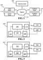
- FIG. 1 depicts a system 100 for monitoring, controlling, and communicating with at least one monitoring device 110 and/or at least one control device 111.
- System 100 includes an operations center 105 in communication with at least one monitoring device 110 and/or one control device 111.
- operations center 105 and devices 110 and 111 there is bi-directional communication between operations center 105 and devices 110 and 111.
- Communications can be simplex or duplex.
- Communication can occur over any communications network 115 known in the art, including but not limited to wired networks, wireless networks, Zigbee networks, Bluetooth networks, Z-wave networks, WiFi networks, WiMax networks, RF networks, local area networks (LAN), internet networks, wide area networks (WAN), cellular telephone network, hardwired telephone networks, 900 MHz wireless networks, and satellite networks.
- the network is a fixed network.
- the fixed network can be a mesh network or a star network.
- devices 110 and 111 and operations center 105 can be in direct communication or can communicate through an intermediary device, such as a relay, a repeater, a gateway, or other device capable of receiving and retransmitting a message.
- Each monitoring device 110 monitors at least one aspect of the infrastructure.
- the monitored aspect can be one or more of the components of the infrastructure (e.g. pipe conditions, valve conditions, fire hydrant conditions, service line conditions, meter conditions, power line conditions, and battery conditions), commodity conditions (e.g. fluid or gas flow, fluid or gas pressure, fluid or gas temperature, and fluid or gas contaminants), or combinations thereof.
- each monitoring device 110 can be self monitoring. For example the monitoring devices 110 determine if there is a loss of communication, low battery levels, and/or internal damage (e.g. short circuits due to water damage).
- each monitoring device 110 can be structurally stable (e.g.
- valve box fixed to a valve, pipe, utility pole, a hydrant, a valve box, a valve box cover, a meter, a meter box, a meter box cover, a water tower, a water tank, a pumper nozzle, a hose nozzle, or an manhole cover
- movable e.g. allowed to move with or within the flow of water or gas in the pipes.
- a monitoring device 110 or 111 can be coupled to a fire hydrant 405, a seen in FIG. 4B .
- the monitoring device 110 or 111 can be located within a nozzle cap 600 (i.e. in the pumper nozzle, the hose nozzle, or in the fire truck hook up), within a body of the fire hydrant, within a bonnet, attached to an outside of the fire hydrant, or at another location on or within the fire hydrant.
- a housing for the monitoring device 110 or 111 is made of plastic, nylon, other synthetic or natural materials, or any other material that does not block transmissions to and from the monitoring device 110 or 111. For example, as shown in FIG.
- the fire hydrant bonnet 400 can contain a monitoring device 110 and a waterproof container 420 for the monitoring device 110. In some embodiments the fire hydrant bonnet 400 can also contain a power source 425. In another example, as shown in FIG. 4B , the monitoring device 110 can be coupled to the outside of a fire hydrant 405. In another embodiment, shown in FIGs. 5A and 5B , the bonnet 500 of a fire hydrant 505 can be isolated from the flow of water within the fire hydrant 505. For example, there can be a plastic, metal, or other material disc 530 that seals off a portion of the fire hydrant 505 to prevent water from reaching the interior regions of the bonnet 500.
- the communications or monitoring device 110 or control device 111 is positioned within a nozzle cap 600 of a fire hydrant.
- a fire hydrant nozzle cap 600 is a device attached to an outlet nozzle and covers a nozzle opening.
- the nozzle cap 600 is furnished with a nut 605 or other device to permit the application of force to firmly attach the nozzle cap 600 to or to remove it from the outlet nozzle.
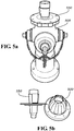
- FIG. 6A depicts an isometric view of an embodiment of the nozzle cap 600.
- nozzle cap 600 is made of a composite, plastic, nylon, other synthetic or natural materials, or any other material that does not block transmissions to and from the monitoring device 110 or control device 111.
- the material has the same fading characteristics of the paint used on the exterior of the fire hydrant.
- the material can have the same resistance to water, UV rays, corrosion, oxidation, or other causes of fading. Thereby, the paint and the nozzle cap 600 appear to be of the same material.
- FIGs. 6B and 6C depict cutaway views of an embodiment of the nozzle cap 600.
- the nozzle cap 600 has an enclosure 610 which creates a cavity into which monitoring device 110 or control device 111 may be located. The cavity is enclosed by a cover 615.
- the enclosure 610 and cover 615 create a water tight seal able to withstand water pressures in excess of 400 psi. In various embodiments, other pressures may be utilized.
- nozzle cap 600 has an antenna cover 620.
- Antenna cover 620 can be made of the same material as nozzle cap 600 or of a different material. The location of the antenna is kept away from metal to achieve greater efficiency.
- Nozzle hydrant threading 625 is provided as a connection means between the nozzle cap 600 and the fire hydrant.
- the nozzle cap 600 also includes enclosure threading 630 as a connection means for the enclosure 610 to connect to the nozzle cap 600.
- the enclosure 610 also includes connection threading 640 designed to mate with the enclosure threading 630.
- An antenna 650 is shown.
- Each node in the network 115 detects errors in transmissions. Error detection can use cyclic redundancy codes using a table based on a defined polynomial or another method of error detection. In alternative embodiments, transmissions can be rerouted if the primary route is blocked or otherwise unavailable. Furthermore, devices 110 and 111 can confirm receipt of a message, e.g. via a hand shake protocol. In instances where confirmation is not received, the message can be resent along the same route or rerouted.
- each monitoring device 110 and each control device 111 is assigned a unique identifier.
- the unique identifier can be related to the devices' geographical locations, street addresses, order of installation, or any other method of identifying the devices 110,111.
- different types of devices 110 and 111 can have unique identifiers that include keys that are unique to that type of device. For example, the identifier for all water meters may begin with a WM, while the identifier for all leak detectors may begin with an LD.
- Each communication to and from a monitoring device 110 and control device 111 may include the unique identifier so that the message is received by the correct monitoring device 110 or control device 111, or so that operations center 105 can determine from where the message was sent.
- Each monitoring device 110 and each control device 111 can be retrofitted to an existing system 100 or device 110,111, can be coupled to a new system 100 or device 110,111, or can be integrated into a new system 100 or device 110,111.
- the system 100 can be connected to, work with, or work independently of a Supervisory Control and Data Acquisition (SCADA) network.
- SCADA Supervisory Control and Data Acquisition
- each monitoring device 110 and each control device 111 has a set of adapters to facilitate coupling the monitoring device 110 or control device 111 to a new or existing system 100 or device 110, 111.
- system 100 is divided into sectors with each sector having at least one monitoring device 110 and/or at least one control device 111.
- Each sector can communicate directly with operations center 105 or each sector can have at least one intermediary communications device that is in communication with the monitoring device 110 and/or control device 111 and operations center 105.
- the sectors are divided up by geographical location. For example, all of the devices in one neighborhood can be in a single sector and there is one sector for each neighborhood.
- one intermediary communications device can service multiple sectors.
- each monitoring device 110 and/or control device 111 can communicate with adjacent monitoring devices 110 and/or control devices 111.
- each monitoring device 110 and/or control device 111 can act as a transceiver or relay by receiving messages intended for another device 110,111 or for the operations center 105 and forwarding the message.
- monitoring devices 110 and control devices 111 can communicate only within their sector. In other embodiments, monitoring device 110 and control device 111 can communicate with devices 110,111 in other sectors.
- Each monitoring device 110, control device 111, and/or the operations center 105 may be able to determine if a transmitted message was received by the intended device 110,111 and, if not, may be able to reroute the message until the message is properly received.
- relay devices can be implemented in the system to further extend the range of communications. For example, relay devices can be placed on utility poles, on municipal buildings, within fire hydrants, and/or under manhole covers.
- devices 110 and 111 communicate over a mesh network. In the mesh network, devices 110 and 111 can communicate with other devices 110 and 111 within the mesh network.
- Operations center 105 can set specified communications pathways derived from routing tables.
- Operations center 105 can be located at a municipality office, a private or public company, a fire station, a police station, or any other entity that monitors operations center 105.
- operations center 105 can be remotely hosted and accessible by the Internet.
- operations center 105 can take advantage of cloud computing (e.g. a network of remotely hosted computers, servers, and data storage devices). Compared to non-remotely hosted computer networks, cloud computing can increase ease of use, increase access, increase security, decrease costs, be custom tailored, and provide an unrestricted expansion of storage space.
- One or more operations centers 105 can be located at different entities and each operations center 105 can monitor a different aspect of system 100.
- the water usage aspect can be monitored by a water utility company and the gas leaks can be monitored by the gas utility company and/or the fire department.
- there are redundant operations centers 105 where at least two operations centers 105 monitor the same aspect of system 100. Operations center 105 can send transmissions to update the firmware of devices 110 and 111.
- FIG. 2 is a schematic of a monitoring device unit 200.
- Monitoring device unit 200 includes a processor 205.
- Processor 205 is coupled to at least one input port 210 for receiving data from sensors 215.
- Processor 205 is also coupled to a transceiver 220 for sending and receiving signals.
- Processor 205 is coupled to a data storage unit 230.
- Data storage unit 230 can hold a predetermined amount of data received from the sensors 215.
- data storage unit 230 can hold data for a predetermined amount of time (e.g. one day, one week, or one month), can hold a predetermined number of readings (e.g. 10 readings, 100 readings, 1000 readings), or can hold data until directed to purge the data by the operations center 105.
- data storage unit 230 can hold instructions for processor 205 to execute upon prompting from the operations center 105.
- Processor 205 compiles at least some of the data stored in data storage unit 230 for transmitting to the operations center 105.
- Each monitoring device unit 200 may collect data and/or transmit data continuously, at specific intervals, or randomly. In embodiments where the monitoring device unit 200 collects and transmits data in a non-continuous configuration, monitoring device unit 200 may turn off or reduce power consumption during the non-data collecting periods to save energy.
- Processor 205 is coupled to a power source 235.
- Power source 235 can be a unit capable of powering processor 205 and devices attached to processor 205.
- power source 235 can be a battery, solar panel array, wind turbine, water turbine, electrical lines, or combinations thereof.
- there is also a backup power source such as a battery. The power may derive from the operation of the system 100.
- processor 205 is coupled to at least one sensor 215 that monitors at least one condition associated with the monitoring device.
- Sensors 215 can determine the status of a device.
- Sensors 215 can be directly wired to processor 205 or can use wireless communication to send and receive signals from processor 205.
- Sensors 215 can be positioned within the monitoring device or be external to the monitoring device. In alternative embodiments, sensors 215 are positioned remote from the monitoring device. For example a sensor can be positioned in a fire hydrant, on a nearby building, or on a utility pole.
- the same communications protocol can be used in the sensor/processor communication as in the processor/operations center communication, or different communications protocols can be used in the sensor/processor communication from in the processor/control center communication.
- the sensor/processor communications can use RF protocols while the processor/control center communications can be over a wired network.
- sensor 215 is a use monitor.
- the use monitor records the amount of water, gas, electricity, or other commodity that is used by a customer over a specified period of time.
- the use monitor can continuously record the amount of the commodity used or the use monitor can provide a signal to processor 205 that the commodity is in use.
- Processor 205 can transmit a signal to the operations control to alert the operations center 105 that the monitoring device 110 is being used and/or how much of the commodity is flowing through the sensor 215.
- the operations center 105 can request a reading from the use monitor on demand.
- the processor 205 or the operations center 105 can determine based on the use, if there is unauthorized use of the commodity.
- At least one of processor 205 or the operations center 105 can generate an alarm that there is unauthorized use. For example, in embodiments where the use monitor is coupled to a fire hydrant 405, if the use monitor indicates that the fire hydrant 405 is in use, however no fire is reported, the operations center 105 can disseminate an alert that there is potential misuse of the fire hydrant 405.
- At least one sensor 215 is a tamper sensor.
- the tamper sensor can be a motion detector, a contact sensor, a rotation sensor, a touch sensor, a proximity sensor, a biofeedback sensor, a temperature sensor, a capacitance sensor, a resistance sensor, or any other sensor that is able to detect the presence of an object.
- the tamper sensor can send a message to processor 205 when the tamper sensor detects an event.
- the processor 205 will then evaluate the event to determine if a device being monitored is being tampered with or will relay the message to the operations center 105 for evaluation.
- the monitored device can be a fire hydrant, utility meter, valve, manhole cover, pump, or any other device that may be tampered with.
- processor 205 and the operations center 105 can generate an alarm that the device is being tampered with.
- the monitoring device may activate a tamper prevention device (described below).
- the operations center 105 will send a transmission to processor 205 telling processor 205 to disregard messages from the tamper sensor for a predetermined period of time or until another message is received from the operations center 105 telling processor 205 to resume monitoring for tamper events.
- the operations center 105 will send a message to processor 205 to temporarily disregard any tamper events. Once the fire department is finished using the fire hydrant the operations center 105 will send a message to processor 205 to start monitoring for tamper events again.
- At least two of sensors 215 are leak detectors.
- Each leak detector can include an in-pipe leak detector and/or an exterior leak detector.
- the leak detectors are vapor sensors.
- the leak detectors use acoustic monitoring to determine presence and location of a leak. The energy generated from a leak is transmitted within a pipe through the commodity as well as through the pipe wall.
- Each leak detector can detect the vibrations made by the leak in the commodity or the pipe wall, joint or service line. To determine the location of a leak, at least two detectors must detect the same leak.
- the typical velocity of sound in water is about 1500 m/s while the typical speed of sound through an iron pipe is 5100 m/s.
- the velocity can be measured empirically. For example, if the leak is exactly midway between the two detectors the sound would reach both detectors at the same time. Each detector may monitor continuously or at predetermined periods of time.
- the leak detectors can send a message to processor 205 when the leak detectors detect an event.
- the processor 205 can then evaluate the event to determine if there is a leak and how severe the leak is or can relay the message to the operations center 105 for evaluation.
- at least one of processor 205 or the operations center 105 can generate an alert that there is a leak if the leak is determined to be severe enough to warrant attention.
- At least one sensor 215 is a smoke detector.
- the smoke detector can be a photoelectric detector, an ionization detector, or any other device that can detect the presence of smoke.
- the smoke detector can be located within the monitoring device or exterior to the monitoring device.
- the smoke detector monitors continuously for smoke.
- the smoke detector can send a message to processor 205 when the smoke detector detects an event.
- the processor 205 can then evaluate the event to determine if there is smoke or can relay the message to the operations center 105 for evaluation.
- at least one of processor 205 or the operations center 105 can generate an alert that there is smoke.
- At least one sensor 215 is a temperature sensor.
- the temperature sensor can be a contact sensor (e.g. thermocouples, thermistors, liquid-in-glass thermometers, resistance temperature detectors, filled system thermometers, bimetallic thermometers, semiconductor temperature sensors, and phase change indicators) or a non-contact sensor (e.g. radiation thermometers, thermal imagers, ratio thermometers, optical pyrometers, and fiber optic thermometers).
- the temperature sensor can be located within the monitoring device or exterior to the monitoring device. In one embodiment, the temperature sensor monitors continuously for the temperature to rise above or drop below a predetermined threshold. The temperature sensor can send a message to processor 205 when the temperature sensor detects a temperature beyond the thresholds.
- the processor 205 can then evaluate the event to determine if there the temperature is a problem (such as freezing pipes or fire) or can relay the message to the operations center 105 for evaluation. Upon detection of undesirable temperatures, at least one of processor 205 or the operations center 105 can generate an alert that there is an undesirable temperature condition.
- a problem such as freezing pipes or fire
- At least one sensor 215 is a rust and/or corrosion sensor.
- the corrosion sensor can detect rust and/or corrosion using any method known in the art, including but not limited to liquid penetration inspection, magnetic particle inspection, radiographic inspection, visual inspection, eddy current inspection, ultrasonic inspection, and thermographic inspection.
- the corrosion sensor can send a message to processor 205 when the corrosion sensor detects a rust or corrosion beyond a threshold value.
- the processor 205 can then evaluate the rust or corrosion to determine if there is a problem or can relay the message to the operations center 105 for evaluation.
- at least one of processor 205 or the operations center 105 can generate an alert that there is an undesirable amount of rust or corrosion.
- At least one sensor 215 is a fluid flow sensor.
- the fluid flow sensor can be used either in gas systems or liquid systems.
- the fluid flow sensor can detect direction of the flow, turbidity of the flow, velocity of the flow, density of the flow, viscosity of the flow, and/or any other aspect of the flow.
- the fluid flow sensor may be a velocimeter, a laser-based interferometer, a vane, a rotary potentiometer, a Hall effect sensor, a device to measure heat transfer caused by the flowing fluid, or any other device know in the art to measure the flow of fluid.
- the fluid flow sensor can send a message to processor 205 when the fluid flow sensor detects a flow anomaly.
- the processor 205 can then evaluate the event to determine if the anomaly is a problem or can relay the message to the operations center 105 for evaluation. Upon detection of an anomaly, at least one of processor 205 and the operations center 105 can generate an alert that there is an anomaly.
- At least one sensor 215 is a pressure sensor.
- the pressure sensor is positioned within the flow of fluid or area in which the pressure is being sensed.
- the pressure sensor can be positioned at the base of a fire hydrant and in the water to determine the water pressure within water system, in a pipe to determine gas or water pressure within a gas or water system, or in a room to determine air pressure within the room.
- the pressure sensor can be a piezoresistive strain gauge, a capacitive gauge, an electromagnetic gauge, a piezoelectric device, or any other device know in the art to measure pressure.
- the pressure sensor can send a message to processor 205 when the pressure sensor detects a pressure anomaly.
- the processor 205 can then evaluate the event to determine if the anomaly is a problem or can relay the message to the operations center 105 for evaluation. Upon detection of an anomaly, at least one of processor 205 or the operations center 105 can generate an alert that there is an anomaly.
- At least one sensor 215 is a water quality monitor.
- the water quality monitor can monitor a single aspect of water flowing through the system 100 or multiple aspects of the water.
- the water quality monitor can monitor one or more of the water's bacteria levels, pharmaceutical levels, alkalinity, chlorine and/or chloramine levels, hardness, pH levels, peroxide content, iron levels, nitrate levels, nitrite levels, arsenic levels, pollution levels, oxygen levels, biomass levels, and/or any of the other contaminants regulated by the Environmental Protection Agency (EPA).
- EPA Environmental Protection Agency
- all the devices can monitor the same aspects, each device can monitor a different aspect, or a combination thereof.
- the water quality monitors test the water continuously, however, in alternative embodiments, the water quality monitors test the water at predetermined time intervals (e.g. once a hour, once a day, once a week, etc.). Each water quality monitor relays data to processor 205.
- Processor 205 can store the data on data storage unit 230 or transmit the data to the operations center 105.
- Either processor 205 or the operations center 105 can monitor the data received from the water quality monitors to determine if there is a change in the levels of the contaminants or if the levels of the contaminants rise above a threshold level. Upon detection of unsafe contamination levels, at least one of processor 205 or the operations center 105 can generate an alert that there is contamination in the water system.
- the operations center 105 can determine if there is a change in the aspect of the water from the location of one monitoring device to the location of the other. If there is a change, the operations center 105 can generate an alert that there is a change in the water system and output the approximate location of the change in the water system.
- At least one sensor 215 is an air quality monitor.
- the air quality monitor can monitor a single aspect of the air or multiple aspects of the air.
- the air quality monitor can monitor the air within a facility or ambient air.
- the air quality monitor can monitor one or more of the air's benzene levels, carbon disulfide levels, urethane levels, formaldehyde levels, phosphorus levels, naphthalene levels, parathion levels, quinoline levels, trifluralin levels, and/or any of the other contaminants whose acceptable levels have been set by the Environmental Protection Agency.
- all the devices can monitor the same aspects or each device can monitor a different aspect, or a combination thereof.
- the air quality monitors test the air continuously, however, in preferred embodiments, the air quality monitors test the air at predetermined time intervals (e.g. once a hour, once a day, once a week, etc.). Each air quality monitor relays data to processor 205.
- Processor 205 can store the data on data storage unit 230 or transmit the data to the operations center 105.
- Either processor 205 or the operations center 105 can monitor the data received from the air quality monitors to determine if there is a change in the levels of the contaminants or if the levels of the contaminants rise above a threshold level. Upon detection of unsafe contamination levels, at least one of processor 205 or the operations center 105 can generate an alert that there is contamination in the air.
- the operations center 105 can determine if there is a change in the aspect of the air from the location of one monitoring device to the location of the other. If there is a change, the operations center 105 can generate an alert that there is a change in the air and output the approximate location of the change in the aspect of the air. Furthermore, in embodiments where there is a time stamp associated with each reading, the operations center 105 can determine the approximate direction and speed at which the contaminant is moving.
- At least one sensor 215 is a radiation detector.
- the radiation detector can distinguish between natural sources of radiation and artificial sources of radiation or can distinguish between normal levels of radiation and abnormal levels of radiation.
- the radiation detector detects ionizing radiation.
- Ionizing radiation consists of subatomic particles or electromagnetic waves that are energetic enough to detach electrons from atoms or molecules, ionizing them. Examples of ionizing particles are energetic alpha particles, beta particles, and neutrons.
- the ability of an electromagnetic wave (photons) to ionize an atom or molecule depends on its frequency. Radiation on the short-wavelength end of the electromagnetic spectrum-high frequency ultraviolet, x-rays, and gamma rays-is ionizing.
- the radiation detector is one of a dosimeter, a Geiger counters, or a scintillation counters.
- Dosimeters measure an absolute dose received over a period of time. Ion-chamber dosimeters resemble pens, and can be clipped to one's clothing. Film-badge dosimeters enclose a piece of photographic film, which will become exposed as radiation passes through it. Ion-chamber dosimeters must be periodically recharged, and the result logged. Film-badge dosimeters must be developed as photographic emulsion so the exposures can be counted and logged; once developed, they are discarded. Another type of dosimeter is the TLD (Thermoluminescent Dosimeter).
- TLDs contain crystals that emit visible light when heated, in direct proportion to their total radiation exposure.
- TLDs can be re-used after they have been 'read'.
- Geiger counters and scintillation counters measure the dose rate of ionizing radiation directly.
- the radiation detector is a solid-state device.
- the radiation detector can relay the detection to processor 205.
- Processor 205 can save the detection on data storage unit 230 or transmit a message regarding the detection to the operations center 105.
- Processor 205 or the operations center 105 can evaluate the detection and act in accordance with the purpose of the radiation detector. For example, if the radiation detector detects radiation over a threshold level, processor 205 or the operations center 105 can generate an alert that there are unsafe radiation levels.
- At least one sensor 215 is a motion detector.
- the motion detector can be a radar-based motion detector, a photo-sensor motion detector, a passive infrared motion detector, a magnetic motion detector, a pressure sensitive motion detector, or any other device capable of detecting the motion of objects.
- the motion detector can be used, for example, to count the number of cars passing through an intersection to control a traffic light, for tamper prevention as described above, for security purposes, and/or to control street lights.
- the motion detector can be placed within the monitoring device or exterior to the monitoring device.
- the motion detector can relay the detection to processor 205.
- Processor 205 can save the detection on data storage unit 230 or transmit a message regarding the detection to the operations center 105.
- Processor 205 or the operations center 105 can evaluate the detection and act in accordance with the purpose of the motion detector. For example, if the motion detector detects a predetermined number of vehicles have passed the monitoring device, processor 205 or the operations center 105 can cause a traffic light to switch from green to red. As a second example, if the motion detector detects a motion after a predetermined time, e.g. after sunset, processor 205 or the operations center 105 can cause the street lights near the monitoring device to illuminate for a predetermined period of time.
- a predetermined time e.g. after sunset
- At least one sensor 215 is a tiltmeter.
- the tiltmeter can be a pendulum, a water tube, a bubble-level meter, and/or a MEMS electronic meter.
- the tiltmeter can be located on devices within the system, such as, but not limited to, pipes, fire hydrants, meters, valves, utility poles, manhole covers, and light posts.
- the tiltmeter can send a message to processor 205 when the sensor detects a tilt beyond a threshold value.
- the processor 205 can then evaluate the tilt to determine if there is a problem or can relay the message to the operations center 105 for evaluation.
- at least one of processor 205 or the operations center 105 can generate an alert that there is an undesirable tilt. For example, if a utility pole is struck by a car, the tiltmeter will indicate that the utility pole is tilting at an undesirable level and the operations center 105 can alert the municipality to send out a repair crew to assess the situation and repair the utility pole.
- At least one sensor 215 is a proximity sensor.
- the proximity sensor can use electromagnetic technology, electrostatic technology, infrared technology, or a touch switch.
- the proximity sensor can detect if devices are properly closed or if devices are improperly touching.
- the proximity sensor can send a message to processor 205 when the proximity sensor detects proximity beyond a threshold value.
- the processor 205 can then evaluate the proximity to determine if there is a problem or can relay the message to the operations center 105 for evaluation.
- at least one of processor 205 or the operations center 105 can generate an alert that there is an undesirable proximity. For example, if a valve is improperly closed, the proximity sensor will indicate that the valve is not closed and processor 205 can alert the municipality to take proper actions to close the valve.
- At least one sensor 215 is a visual or audio device.
- the device can be an infrared camera, a video camera, a still camera, a digital camera, a film camera, a mobile vision device, a microphone, a vibration detector, combinations thereof, or any other device capable of acquiring an image or sound.
- the device is a digital video camera that takes video images continuously.
- the device is a digital still camera that takes still images at regular intervals or upon command from processor 205.
- the device can be a traffic camera and take a picture when instructed to by processor 205, for example upon determination that a vehicle is running a red light.
- the device is used to perform visual inspections of the system infrastructure.
- the field of view of the device can include a device within the system that is apt to corrode and the camera can provide an easy method to visually inspect any degradation of the device.
- the device can send image data to processor 205 where the data is stored on data storage unit 230 or is transmitted to the operations center 105.
- image or sound data is streamed continuously from the device to processor 205 and from processor 205 to the operations center 105.
- the data stream can either be live or delayed.
- the device can be located on the monitoring device, near the monitoring device, or within the monitoring device with a portion of the device extending outside the monitoring device or with a hole in the monitoring device through which the device can obtain images or sounds.
- the device is positioned on an actuator.
- the actuator can move to reposition the field of view of the device.
- the actuator can move upon demand from processor 205 or can move autonomously. In the embodiments where the actuator moves autonomously, the movement can be continuous or sporadic.
- At least one sensor 215 is a Global Positioning System (GPS) receiver.
- GPS Global Positioning System
- the GPS receiver is located on devices within the system 100, such as, but not limited to, pipes, fire hydrants, meters, valves, utility poles, manhole covers, and light posts.
- the GPS receiver can send a message to processor 205 indicating GPS location.
- the processor 205 can then relay the message to the operations center 105 for evaluation, conformation, and documenting.
- at least one of processor 205 or the operations center 105 can generate an alert that the GPS receiver has moved, possibly indicating that the device has been dislodged, tampered with, or stolen.
- the GPS location can be used, for example, by emergency responders to locate fire hydrants, or repair crews to determine the location of a buried device.
- the operations center 105 can disseminate information to the emergency responders or repair crews to easily locate the device.
- the dissemination can occur by any method, including but not limited to, verbally, over a telecommunications network (e.g. to a smart phone or portable computer), or over a shortwave radio.
- the sensor can provide updated locations of the monitoring device to track, for example, the flow or contamination levels within the flow.
- sensors 215 connected to monitoring device unit 200 can include, but are not limited to, flow rate meters, backflow meters, system status monitors, and power level monitors.
- Control device 300 includes a processor 305.
- Processor 305 is coupled to at least one output port 310 for controlling an output device 340.
- Processor 305 is also coupled to a transceiver 320 for sending and receiving signals.
- Processor 305 is communicatively coupled to output port 310.
- Output port 310 is connected to at least one output device 340.
- Each output device 340 can have the same purpose or each output device 340 can have a different purpose, or combinations thereof.
- Output devices 340 can be located within control device 300 or external to control device 300, as shown.
- output devices 340 can be attached to control device 300 or can be remote from control device 300.
- Output devices 340 communicate with output port 310 through wired or wireless communication channels.
- output devices 340 are capable of bidirectional communication.
- control device 300 is an integral part of a monitoring device. In such embodiments, the control device 300 and the monitoring device can share the same processor and/or transceiver.
- processor 305 is coupled to a data storage unit 330 that may be a database in some embodiments.
- Data storage unit 330 may store instructions for processor 305 of how to control output devices 340.
- processor 305 is coupled to a power source 335.
- Power source 335 can be any device capable of powering processor 305 and any devices attached to processor 305.
- power source 335 can be a battery, solar panel array, wind turbine, water turbine, electrical lines, or combinations thereof.
- there is also a backup power source such as a battery.
- At least one output device 340 is an actuator control device.
- the actuator control device can control any type of actuator, including but not limited to, a tamper prevention device, a locking device, a camera motion device, a fire hydrant nut opening device, or a valve.
- the actuator control device can control the actuator autonomously or upon demand from processor 305. For example, upon receiving a signal that a particular event has been sensed, processor 305 may send a command to the actuator control device to act in a particular manner. Likewise, in some embodiments the control signal may come from the operations center 105.
- the actuator can be mechanical, electrical, or a combination thereof.
- At least one output device 340 is an alarm.
- the alarm can be a visual alarm, an audible alarm, a tactile (i.e. vibration) alarm, or a combination thereof.
- the alarm can be located within the monitoring device, exterior to the monitoring device, at the operations center 105, remote from the system, or any other location sufficient to alert. Furthermore, there can be more than one alarm at different locations. For example, in the embodiments where there is a smoke detector, there can be an audible alarm located within the fire detector to alert people around the monitoring device of a potential fire, there can be an audible alarm at the fire station to alert the fire department of the potential fire, and there can be a visual alarm at the gas utility company to indicate that the flow gas in the vicinity of the potential fire should be shut off.
- the alarm is controlled by the processor 305, while in other embodiments the alarm is controlled by the operations center 105. In various embodiments, the alarm has an on/off switch controllable locally.
- At least one output device 340 is a tamper prevention device.
- the tamper prevention device can be a mechanical lock, an alarm, a light, an electrical shock generator, a retaining device, an electrical lock, or any other device capable of preventing tampering.
- the tamper prevention device may merely deter tampering or may incapacitate a person who is trying to tamper with the device, depending on the level of security.
- the tamper prevention device is controlled by the processor 305, while in other embodiments the tamper prevention device is controlled by the operations center 105.
- At least one output device 340 is a Radio-Frequency Identification (RFID) device.
- RFID Radio-Frequency Identification
- the RFID device can broadcast information about the device to which it is attached. For example, the RFID device may broadcast manufacturer information, location information, last service date, device information (e.g. make, model, and/or year), current status (e.g. a valve can broadcast if it is open or closed), etc.
- the RFID device is updateable by the processor 305 or by the operations center 105.
- the RFID device can be either an active (e.g. battery powered) or passive (e.g. require an external source to provoke signal transmission) device.
- a system of the disclosure is monitoring a water distribution infrastructure.
- the system is used to automatically control the water pressure within the system.
- Such a system includes a number of water meters disbursed throughout the infrastructure relaying real time use information to a control center.
- the operations center Upon a determination by the operations center that there is low usage of the system (e.g. at night) based on information received by a predetermined number of the water meters, the operations center causes pumps supplying pressure within the system to reduce or cease pumping. Thereby cutting down on the electricity used by the pumps while maintaining enough pressure throughout the infrastructure to satisfy any water needs.
- the determination to reduce or cease pumping can be also based on information received from pressure sensors disbursed throughout the infrastructure. For example, if the pressure within the infrastructure exceeds a threshold value, the operations center causes the pumps to reduce or cease pumping.
- the system is used to assist in maintaining the infrastructure. Water pipes and valves are often buried underground making it difficult to locate, assess the status of the devices, and repair them if necessary.
- each device is equipped with a monitoring the device.
- the monitoring device may monitor for corrosion using a corrosion monitor, geographical location using a GPS receiver, and leaks using a leak detector.
- the monitoring device Upon detection of corrosion and/or a leak, the monitoring device sends a message to the operations center where the information is analyzed.
- the operations center is able to make a determination if the corrosion and/or leak is severe enough to warrant fixing, if the corrosion and/or leak should be watched to determine if it worsens, or if the corrosion and/or leak can be ignored.
- the operations center will also alert a person of the situation for further assessment.
- the operations center disseminates information to a repair crew and redirects water flow away from the device.
- information can include location of the device, based on data received the GPS receiver, problem associated with the device, device information (e.g. make, model, and/or year), etc.
- the monitoring device can also be equipped with a RFID transmitter, which transmits at least some of the above information.
- the repair crew receives the information on a smart phone, a portable computer, or other device capable of receiving such information.
- the operations center updates the system to indicate a new last repaired date for the device.
- the system is monitored by several entities within a municipality at the same time.
- a fire department Upon detection of smoke by a monitoring device, the control center alerts each entity of a potential fire.
- the location of the potential fire is determined by cross-referencing the ID number of the monitoring device with a lookup table or based on information received from a GPS receiver.
- the fire department uses the location information to send out emergency response personnel to the vicinity of the potential fire.
- the gas utility uses the location information to divert or shut off gas flow to the vicinity of the potential fire.
- the water utility uses the location information to divert water to or increase water pressure in the vicinity of the potential fire as well as determines if any fire hydrants in the vicinity of the potential fire are potentially damaged (e.g. are tilted at an unusual angle, are receiving no or little water pressure, or have been tampered with) based on information received from monitoring devices attached to the fire hydrants.
- the location of the fire hydrants is determined by cross-referencing the ID number of the monitoring device with a lookup table or based on information received from a GPS receiver.
- the water utility automatically alerts the fire department as to which fire hydrants to use.
- the water utility also disables any tamper prevention devices associated with the fire hydrants.
- the electric utility receives a signal that additional pressure may be needed within the water system and provides an increased electrical load to the water pumps. Additionally, the traffic control center adjusts traffic lights en route from the fire station to the vicinity of the potential fire to assist the fire trucks in arriving quickly and safely.
- the system is used to monitor contamination of the fluid flowing through the system.
- the system includes pressure sensors, leak detectors and contamination detectors. Leaks within the system can cause a pressure drop throughout the system which can lead to contaminants being drawn into the system. For example, if a pipe is under water and the pressure inside the pipe drops below the pressure outside the pipe, the exterior water will flow into the pipe. Therefore, the system has several monitoring devices to check for such potential or actual contamination.
- the pressure sensors will indicate if the pressure within the system drops below a threshold level at which contaminants can be drawn into the system.
- the leak detectors will indicate that there is a leak through which contaminants can enter the system. While the contamination detectors will indicate if there is contamination within the system, indicating a possible breach of the infrastructure of the system.
Claims (8)
- Düsenkappenanordnung, umfassend:eine Düsenkappe (600); undeine Kommunikationsvorrichtung (110), die mit der Düsenkappe (600) gekoppelt ist, wobei die Kommunikationsvorrichtung (110) eine Komponente eines Infrastrukturüberwachungssystems ist,wobei die Düsenkappe (600) eine innere Kavität definiert,wobei die Düsenkappe (600) eine Einhausung (610) und eine Abdeckung (615), um die Einhausung (610) abzudichten, enthält,wobei die Abdeckung (615) eine wasserdichte Dichtung an der Einhausung (610) erzeugt,wobei die Kommunikationsvorrichtung (110) innerhalb der Einhausung (610) und der Abdeckung (615), im Inneren der inneren Kavität positioniert ist,wobei die Düsenkappe (600) an deren unteren Ende ein Düsenhydrantengewinde (625) enthält, das als Verbindungsmittel zwischen der Düsenkappe (600) und einem Feuerhydranten bereitgestellt ist,dadurch gekennzeichnet, dassdie Düsenkappe (600) an deren oberen Ende eine Antennenabdeckung (620) aufweist,wobei die Düsenkappe (600) an deren oberen Ende ein Einhausungsgewinde (630) als Verbindungsmittel für die Einhausung (610) enthält, um die Düsenkappe (600) zu verbinden und die Einhausung (610) an deren oberen Ende ein Verbindungsgewinde (640) enthält, das ausgebildet ist, zu dem Einhausungsgewinde (630) zu passen.
- Düsenkappenanordnung nach Anspruch 1, wobei die Kommunikationsvorrichtung (110) gegenüber Wasser isoliert ist.
- Düsenkappenanordnung nach Anspruch 1, wobei die Düsenkappe (600) ein Kompositmaterial umfasst.
- Düsenkappenanordnung nach Anspruch 3, wobei das Kompositmaterial nicht mit Drahtlossignalen interferiert.
- Düsenkappenanordnung nach Anspruch 1, wobei die Abdeckung (615) und Einhausung (610) wasserdicht bis zu 400 psi sind.
- Düsenkappenanordnung nach Anspruch 1, wobei die Verbindung zwischen der Einhausung (610) und der Düsenanordnung (600) wasserdicht bis zu 400 psi ist.
- Düsenkappenanordnung nach Anspruch 1, wobei die Düsenkappe (600) mit einem Feuerhydrant gekoppelt ist.
- Feuerhydrant umfassend eine Düsenkappenanordnung nach einem der Ansprüche 1 bis 7.
Applications Claiming Priority (2)
| Application Number | Priority Date | Filing Date | Title |
|---|---|---|---|
| US35546810P | 2010-06-16 | 2010-06-16 | |
| PCT/US2011/035374 WO2011159403A1 (en) | 2010-06-16 | 2011-05-05 | Infrastructure monitoring devices, systems, and methods |
Publications (3)
| Publication Number | Publication Date |
|---|---|
| EP2582886A1 EP2582886A1 (de) | 2013-04-24 |
| EP2582886A4 EP2582886A4 (de) | 2016-12-07 |
| EP2582886B1 true EP2582886B1 (de) | 2019-11-27 |
Family
ID=45327603
Family Applications (1)
| Application Number | Title | Priority Date | Filing Date |
|---|---|---|---|
| EP11796120.1A Active EP2582886B1 (de) | 2010-06-16 | 2011-05-05 | Vorrichtungen, systeme und verfahren zur infrastrukturüberwachung |
Country Status (7)
| Country | Link |
|---|---|
| US (7) | US8931505B2 (de) |
| EP (1) | EP2582886B1 (de) |
| JP (2) | JP5654124B2 (de) |
| AU (1) | AU2011265675B2 (de) |
| CA (5) | CA3177996A1 (de) |
| MX (3) | MX348843B (de) |
| WO (1) | WO2011159403A1 (de) |
Families Citing this family (127)
| Publication number | Priority date | Publication date | Assignee | Title |
|---|---|---|---|---|
| US7444401B1 (en) | 2002-11-18 | 2008-10-28 | Arkion Systems Llc | Method and apparatus for inexpensively monitoring and controlling remotely distributed appliances |
| CA2741843C (en) | 2008-10-27 | 2018-05-08 | Mueller International, Llc | Infrastructure monitoring system and method |
| JP2012527706A (ja) | 2009-05-22 | 2012-11-08 | ミューラー インターナショナル インコーポレイテッド | インフラ監視装置、システム、および方法 |
| MX348843B (es) | 2010-06-16 | 2017-06-26 | Mueller Int Llc * | Dispositivos, sistemas y métodos de monitoreo de infraestructura. |
| US8335596B2 (en) * | 2010-07-16 | 2012-12-18 | Verizon Patent And Licensing Inc. | Remote energy management using persistent smart grid network context |
| US8833390B2 (en) | 2011-05-31 | 2014-09-16 | Mueller International, Llc | Valve meter assembly and method |
| US8788222B2 (en) | 2011-07-25 | 2014-07-22 | International Business Machines Corporation | Detection of pipeline contaminants |
| US8706325B2 (en) | 2011-07-27 | 2014-04-22 | International Business Machines Corporation | Evaluating airport runway conditions in real time |
| US8990033B2 (en) | 2011-07-27 | 2015-03-24 | International Business Machines Corporation | Monitoring operational conditions of a cargo ship through use of sensor grid on intermodal containers |
| US8538667B2 (en) | 2011-07-28 | 2013-09-17 | International Business Machines Corporation | Evaluating road conditions using a mobile vehicle |
| KR101089644B1 (ko) * | 2011-07-28 | 2011-12-07 | 주식회사 옥타컴 | 개수로 유량측정을 위한 모바일 시스템 및 그 방법 |
| US9291520B2 (en) | 2011-08-12 | 2016-03-22 | Mueller International, Llc | Fire hydrant leak detector |
| US9146112B2 (en) | 2011-10-04 | 2015-09-29 | International Business Machines Corporation | Mobility route optimization |
| US9322657B2 (en) | 2011-10-04 | 2016-04-26 | International Business Machines Corporation | Mobility route optimization |
| US9207089B2 (en) | 2011-10-04 | 2015-12-08 | International Business Machines Corporation | Mobility route optimization |
| US8855569B2 (en) | 2011-10-27 | 2014-10-07 | Mueller International, Llc | Systems and methods for dynamic squelching in radio frequency devices |
| US8660134B2 (en) | 2011-10-27 | 2014-02-25 | Mueller International, Llc | Systems and methods for time-based hailing of radio frequency devices |
| US9413689B1 (en) | 2011-11-11 | 2016-08-09 | On Track Technologies Inc. | Mobile intelligent tracking and communication hub |
| US9287963B2 (en) | 2012-04-20 | 2016-03-15 | Mueller International, Llc | Relay modules for communication within a mesh network |
| MX354641B (es) * | 2012-05-25 | 2018-03-14 | Mueller Int Llc | Indicador de posición para válvulas. |
| HRP20120603A2 (hr) * | 2012-07-23 | 2014-01-31 | Igor IGNAC | Telemetrijski hidrant za mjerenje, prikupljanje i bežiäśno slanje izmjerenih vrijednosti u bazu podataka na udaljeno raäśunalo |
| MY175444A (en) | 2012-10-26 | 2020-06-26 | Mueller Int Llc | Detecting leaks in a fluid distribution system |
| US20140158920A1 (en) * | 2012-12-08 | 2014-06-12 | Masco Corporation | Digital proximity sensor |
| US9217999B2 (en) | 2013-01-22 | 2015-12-22 | General Electric Company | Systems and methods for analyzing data in a non-destructive testing system |
| DE102013201299B4 (de) * | 2013-01-28 | 2016-09-29 | Matthias Deufert | Armatur für Löschwassersystem |
| WO2014115039A2 (en) * | 2013-01-28 | 2014-07-31 | Aquarius Spectrum Ltd. | Method and apparatus for detecting leaks in a pipeline network |
| US8614745B1 (en) | 2013-02-04 | 2013-12-24 | Wasmeyyah M. A. S. Al Azemi | Fire hydrant monitoring system |
| CA2900965C (en) | 2013-03-15 | 2021-09-07 | Mueller International, Llc | Systems for measuring properties of water in a water distribution system |
| JP6066797B2 (ja) * | 2013-03-28 | 2017-01-25 | 積水化学工業株式会社 | 状況管理支援システム及び状況管理支援方法 |
| JP5858439B2 (ja) * | 2013-04-15 | 2016-02-10 | 山大機電株式会社 | 河川における取水装置 |
| US9541432B2 (en) | 2013-05-17 | 2017-01-10 | The United States Of America As Represented By The Administrator Of The U.S. Environmental Protection Agency | Flow imaging and monitoring for synchronized management of wide area drainage |
| KR102126507B1 (ko) * | 2013-12-09 | 2020-06-24 | 삼성전자주식회사 | 센서 데이터 스트림을 처리하는 단말기, 시스템 및 방법 |
| US10438012B2 (en) | 2014-04-04 | 2019-10-08 | Sicpa Holdings Sa | Interface to generate data compatible with an external system in an oil and gas asset supply chain |
| US9494249B2 (en) | 2014-05-09 | 2016-11-15 | Mueller International, Llc | Mechanical stop for actuator and orifice |
| WO2015191324A2 (en) * | 2014-05-30 | 2015-12-17 | Reylabs Inc. | Systems and methods involving mobile indoor energy efficiency exploration, monitoring and/or display aspects |
| TWI676373B (zh) * | 2014-06-20 | 2019-11-01 | 美商3M新設資產公司 | 資料通訊裝置、系統及方法 |
| US9937549B2 (en) | 2014-07-09 | 2018-04-10 | The Boeing Company | Two-stage riveting |
| US9565620B2 (en) | 2014-09-02 | 2017-02-07 | Mueller International, Llc | Dynamic routing in a mesh network |
| US9528903B2 (en) | 2014-10-01 | 2016-12-27 | Mueller International, Llc | Piezoelectric vibration sensor for fluid leak detection |
| PE20170720A1 (es) | 2014-10-14 | 2017-07-04 | Sicpa Holding Sa | Interfaz con plataforma intermedia segura para generar datos compatibles con un sistema externo en una cadena de suministros de recursosde crudo y gas |
| CN104361703A (zh) * | 2014-11-17 | 2015-02-18 | 天津开发区瑞锋科技有限公司 | 一种井盖移除、破损报警装置 |
| GB201506775D0 (en) * | 2015-04-21 | 2015-06-03 | The Technology Partnership Plc | Gas pipe security device |
| US9661156B2 (en) * | 2015-05-21 | 2017-05-23 | Toshiba America Business Solutions, Inc. | Error assistance using heads-up display |
| US11361650B2 (en) * | 2015-06-01 | 2022-06-14 | Vidtek Associates, Inc. | Wireless leak alarm camera and sensors, and wireless valve, apparatus, system and method thereof |
| US10754360B2 (en) * | 2015-06-01 | 2020-08-25 | Vidtek Associates Inc. | Wireless leak alarm, and wireless valve, apparatus, system and a method thereof |
| US11041839B2 (en) * | 2015-06-05 | 2021-06-22 | Mueller International, Llc | Distribution system monitoring |
| ITUB20151837A1 (it) * | 2015-07-01 | 2017-01-01 | Patavina Tech S R L | Sistema per il monitoraggio ed il controllo di estintori e/o idranti e dell’interazione fra di essi |
| IN2015CH04425A (de) * | 2015-08-24 | 2015-09-04 | Wipro Ltd | |
| US10317384B2 (en) | 2015-09-21 | 2019-06-11 | AMI Investments, L.L.C. | Remote monitoring of water distribution system |
| FR3043204A1 (fr) * | 2015-11-02 | 2017-05-05 | Suez Environnement | Methode pour mesurer la degradation par corrosion d'une conduite metallique et appareil mobile de mesure mettant en oeuvre une telle methode |
| DE102016201235A1 (de) | 2016-01-28 | 2017-08-03 | Minimax Gmbh & Co. Kg | Nebellöschanlage |
| CN105561513A (zh) * | 2016-02-04 | 2016-05-11 | 浙江创丰智能电子科技有限公司 | 智慧消防管控系统 |
| CN105561514A (zh) * | 2016-02-04 | 2016-05-11 | 浙江创丰智能电子科技有限公司 | 智慧消防系统 |
| US10283857B2 (en) * | 2016-02-12 | 2019-05-07 | Mueller International, Llc | Nozzle cap multi-band antenna assembly |
| US10305178B2 (en) * | 2016-02-12 | 2019-05-28 | Mueller International, Llc | Nozzle cap multi-band antenna assembly |
| US10267774B2 (en) * | 2016-02-29 | 2019-04-23 | Mueller International, Llc | External noisemaker for pipe systems |
| US20170296851A1 (en) * | 2016-04-19 | 2017-10-19 | Protector Safety Ind., Ltd. | Fire Fighting Sprinkler Device Having Leveling Correcting Function |
| US20170316678A1 (en) * | 2016-04-28 | 2017-11-02 | Brian DeAngelo | Anti-jamming alarm security system |
| CN105862986A (zh) * | 2016-06-08 | 2016-08-17 | 江苏赛达电子科技有限公司 | 防盗消防栓 |
| RU2620023C1 (ru) * | 2016-08-09 | 2017-05-22 | Общество с ограниченной ответственностью "ТЕХНОАС-СК" | Способ определения места течи в трубопроводе и устройство для его осуществления |
| US10094100B2 (en) * | 2016-08-18 | 2018-10-09 | Stephen A Merlo | Water backup prevention system |
| AT519080B1 (de) * | 2016-09-09 | 2018-07-15 | Hawle Service Gmbh | Vorrichtung zum Überwachen eines Hydranten |
| CN106669086B (zh) * | 2016-11-25 | 2018-08-24 | 温州中盟智能科技有限公司 | 一种智能消防栓 |
| WO2018125740A1 (en) * | 2016-12-28 | 2018-07-05 | Itron, Inc. | Measuring contamination to determine leak location |
| US11484740B2 (en) | 2017-02-21 | 2022-11-01 | Hydrantech Ltd. | Method and system for identifying flow in hydrant outlet |
| US10846819B2 (en) * | 2017-04-12 | 2020-11-24 | Southern Methodist University | Method and apparatus to infer structural stresses with visual image and video data |
| US10564014B2 (en) * | 2017-05-30 | 2020-02-18 | Nelson Manufacturing Company | Water consumption meter |
| WO2019005905A1 (en) * | 2017-06-27 | 2019-01-03 | Nch Corporation | SYSTEM AND METHOD FOR AUTOMATED PLUMBING SENSOR WARNING |
| DE102017117426A1 (de) * | 2017-08-01 | 2019-02-07 | Minimax Gmbh & Co. Kg | Feuerlöschanlagenventil |
| US11709222B2 (en) * | 2017-08-14 | 2023-07-25 | Hadronex, Inc. | Manhole cover roadway electromagnetic safety device |
| FR3071166B1 (fr) * | 2017-09-21 | 2020-11-13 | Le Savoir Ind | Dispositif pour surveiller et commander le fonctionnement d'une borne incendie et installation associee |
| CN107866022A (zh) * | 2017-11-08 | 2018-04-03 | 麦克传感器股份有限公司西安分公司 | 一种一体式智能消防栓 |
| CN107929985A (zh) * | 2017-11-21 | 2018-04-20 | 江西荣和特种消防设备制造有限公司 | 消防炮 |
| US20190176987A1 (en) * | 2017-12-13 | 2019-06-13 | James E. Beecham | System and method for fire suppression via artificial intelligence |
| KR101893898B1 (ko) * | 2018-03-05 | 2018-09-03 | 주식회사 엔시드 | 지능형 소화전 |
| BE1026141B1 (nl) * | 2018-03-29 | 2019-10-28 | Hydroko | Ondergrondse brandkraan met een afsluitdop |
| DE102018109734A1 (de) * | 2018-04-23 | 2019-10-24 | Servatius Schneiders | Verfahren und Vorrichtung zur Verbrauchsmessung |
| KR102096978B1 (ko) * | 2018-05-03 | 2020-04-03 | 주식회사 이레소방엔지니어링 | 옥외소화전 불법주차 경고시스템 |
| EP3803312A1 (de) | 2018-06-08 | 2021-04-14 | Orbis Intelligent Systems, Inc. | Rohrsensoren |
| US11733115B2 (en) | 2018-06-08 | 2023-08-22 | Orbis Intelligent Systems, Inc. | Detection devices for determining one or more pipe conditions via at least one acoustic sensor and including connection features to connect with an insert |
| US11698314B2 (en) | 2018-06-08 | 2023-07-11 | Orbis Intelligent Systems, Inc. | Detection device for a fluid conduit or fluid dispensing device |
| US11167161B1 (en) * | 2018-07-10 | 2021-11-09 | Senthuran Pon Suntharalingam | Hydrant monitoring system |
| US10859462B2 (en) | 2018-09-04 | 2020-12-08 | Mueller International, Llc | Hydrant cap leak detector with oriented sensor |
| US11054404B2 (en) * | 2018-10-16 | 2021-07-06 | Novinium, Inc. | Methods of using dilution of a first type to calibrate one or more sensors |
| CN109621273A (zh) * | 2018-10-25 | 2019-04-16 | 安徽新浩信息科技有限公司 | 一种基于人工智能的消火栓压力异常识别方法 |
| US11016189B2 (en) | 2018-11-14 | 2021-05-25 | Honeywell International Inc. | Systems and methods for security system device tamper detection |
| CN109794029A (zh) * | 2018-12-11 | 2019-05-24 | 泉州市晋源消防水暖有限公司 | 一种智能消防栓 |
| JP7440260B2 (ja) * | 2018-12-20 | 2024-02-28 | 株式会社クボタ | 圃場水管理システム及び給水栓制御装置 |
| CN109621269B (zh) * | 2018-12-21 | 2021-03-30 | 安耐特消防装备有限公司 | 一种智能室内消火栓系统 |
| US11342656B2 (en) | 2018-12-28 | 2022-05-24 | Mueller International, Llc | Nozzle cap encapsulated antenna system |
| US11313748B2 (en) | 2019-01-18 | 2022-04-26 | Mueller International, Llc | Pressure monitor housing with cap-engaging projection |
| US11067464B2 (en) | 2019-01-18 | 2021-07-20 | Mueller International, Llc | Wet barrel hydrant with pressure monitoring and leak detection |
| CN109995143A (zh) * | 2019-04-24 | 2019-07-09 | 任金伟 | 一种电气设备安全装置 |
| CN111939510B (zh) * | 2019-05-15 | 2021-10-01 | 北京泽惠风消防技术有限公司 | 一种消火栓试压装置及室内消火栓系统功能检测方法 |
| US11473993B2 (en) | 2019-05-31 | 2022-10-18 | Mueller International, Llc | Hydrant nozzle cap |
| US10934693B2 (en) * | 2019-06-07 | 2021-03-02 | Mueller International, Llc | Hydrant monitoring system |
| US10968609B2 (en) | 2019-06-07 | 2021-04-06 | Mueller International, Llc | Self-contained hydrant monitoring system |
| US10941545B2 (en) * | 2019-06-07 | 2021-03-09 | Mueller International, Llc | Hydrant monitoring system |
| US11400328B2 (en) | 2019-06-07 | 2022-08-02 | Mueller International, Llc | Hydrant monitoring communications hub |
| WO2020264294A2 (en) | 2019-06-27 | 2020-12-30 | Carrier Corporation | Smoke detection and localization based on cloud platform |
| DE102019119258A1 (de) * | 2019-07-16 | 2021-01-21 | VAG GmbH | Armatur |
| CN110237474B (zh) * | 2019-07-31 | 2020-12-18 | 安徽中轩信息技术有限公司 | 一种消防栓 |
| CN110433441B (zh) * | 2019-08-20 | 2020-11-20 | 合肥科大立安安全技术有限责任公司 | 用于消防栓的水压检测系统 |
| NL2023673B1 (en) * | 2019-08-20 | 2021-04-21 | Alliander N V | Energy distribution network |
| CN111195408A (zh) * | 2019-12-31 | 2020-05-26 | 浙江微天下信息科技股份有限公司 | 一种智慧消防栓监控系统 |
| CN111174981A (zh) * | 2020-01-19 | 2020-05-19 | 浙江天地人科技有限公司 | 一种室外消防栓渗水检测方法和系统 |
| US11939750B2 (en) | 2020-02-24 | 2024-03-26 | Avk Holding A/S | Adapter cap for a fire hydrant, a fire hydrant and a method for remote monitoring an open-close status of a fire hydrant |
| US11248367B2 (en) * | 2020-03-03 | 2022-02-15 | Mueller International, Llc | Hydrant nozzle cap spacer |
| US11542690B2 (en) | 2020-05-14 | 2023-01-03 | Mueller International, Llc | Hydrant nozzle cap adapter |
| CN111549957A (zh) * | 2020-05-19 | 2020-08-18 | 郑峰 | 家用或商用厨房吊顶式多功能智能储水箱 |
| CN111643846B (zh) * | 2020-05-25 | 2021-09-14 | 劲源科技发展有限公司 | 一种基于物联网的消火栓智能监测装置 |
| CN111827410A (zh) * | 2020-06-30 | 2020-10-27 | 西安工程大学 | 一种具有定位功能的消防栓系统 |
| US11725366B2 (en) | 2020-07-16 | 2023-08-15 | Mueller International, Llc | Remote-operated flushing system |
| CN112121349A (zh) * | 2020-09-22 | 2020-12-25 | 江西省智能产业技术创新研究院 | 一种室外消防栓物联网监控系统及方法 |
| CN112402884A (zh) * | 2020-10-20 | 2021-02-26 | 嘉合智能科技股份有限公司 | 一种智能消火栓运行状态在线监测系统 |
| US11601506B2 (en) | 2020-12-18 | 2023-03-07 | Itron, Inc. | Disaggregation of gas load to determine gas appliance performance |
| US11733075B2 (en) | 2020-12-18 | 2023-08-22 | Itron, Inc. | Disaggregation of gas load to determine meter or service under-sizing |
| CN112402885A (zh) * | 2020-12-21 | 2021-02-26 | 杭州智缤科技有限公司 | 一种智能消火栓的安装调试方法 |
| CN112526505B (zh) * | 2021-02-08 | 2021-05-07 | 天宇利水信息技术成都有限公司 | 循环缆道雷达波测流系统 |
| CN113262419B (zh) * | 2021-05-28 | 2022-07-01 | 杭州传感器有限公司 | 一种消防栓阀塞、消防系统及其监控方法 |
| TWI783803B (zh) | 2021-12-01 | 2022-11-11 | 台灣電力股份有限公司 | 蒸汽壓力量測方法 |
| WO2023131884A1 (en) * | 2022-01-05 | 2023-07-13 | Tyco Fire Products Lp | Systems and methods for indicating device state |
| WO2023235174A1 (en) * | 2022-06-02 | 2023-12-07 | Ademco Inc. | Pressure data for utility monitoring |
| WO2023239828A1 (en) * | 2022-06-10 | 2023-12-14 | Mueller International, Llc | Hydrant pumper cap communication assembly |
| CN115154975B (zh) * | 2022-08-05 | 2023-02-24 | 连云港腾越电子科技有限公司 | 一种消防栓状态监测系统 |
| CN116099147B (zh) * | 2023-03-09 | 2024-04-16 | 重新定义(杭州)科技发展有限公司 | 一种智能消防管理系统 |
| CN117618843B (zh) * | 2024-01-24 | 2024-04-09 | 劲源科技发展有限公司 | 一种消火栓状态测试感知装置和方法 |
Family Cites Families (691)
| Publication number | Priority date | Publication date | Assignee | Title |
|---|---|---|---|---|
| US1808212A (en) | 1931-06-02 | Meter | ||
| US691904A (en) | 1898-08-20 | 1902-01-28 | David Verner Hallbergh | Water-meter. |
| US1165429A (en) | 1915-01-15 | 1915-12-28 | Adolph Mass | Liquid-meter. |
| US1808209A (en) | 1923-12-21 | 1931-06-02 | Earl George Goodell | Fluid metering system and apparatus |
| US1738094A (en) | 1928-12-03 | 1929-12-03 | Caldwell | Sound-locating apparatus |
| US1788618A (en) | 1929-11-06 | 1931-01-13 | Berkey E Cover | Signal system |
| US2171173A (en) | 1936-12-11 | 1939-08-29 | Frederick C Coyer | Sound pick-up unit |
| US2302529A (en) | 1939-03-07 | 1942-11-17 | Pittsburgh Equitable Meter Co | Dfpeating valve shutoff system |
| US3254528A (en) | 1962-11-23 | 1966-06-07 | Paul L Michael | Transducer mount |
| US3254660A (en) | 1963-12-19 | 1966-06-07 | Itt | Closure operator for valves |
| US3592967A (en) | 1968-05-20 | 1971-07-13 | George A Harris | Ultrasonic detector |
| US3593957A (en) | 1969-08-15 | 1971-07-20 | Eaton Yale & Towne | Diaphragm assembly for pressure operated pilot controlled shutoff valve |
| US3662600A (en) * | 1969-11-05 | 1972-05-16 | Gamon Calmet Ind Inc | Fluid meter |
| US3705385A (en) | 1969-12-10 | 1972-12-05 | Northern Illinois Gas Co | Remote meter reading system |
| US3673856A (en) | 1970-01-20 | 1972-07-04 | Pier L Panigati | Fluid operated sensor |
| US3653261A (en) | 1970-03-06 | 1972-04-04 | Richard Ruben | Pressure demand meter for fluid flow measurement |
| US3672233A (en) | 1970-07-06 | 1972-06-27 | Clare & Co C P | Actuator mechanism |
| US3815129A (en) | 1970-08-20 | 1974-06-04 | Mallory & Co Inc P R | Piezoelectric transducer and noise making device utilizing same |
| US3612922A (en) | 1970-11-10 | 1971-10-12 | Gen Motors Corp | Method of mounting a piezoelectric device |
| US3731534A (en) | 1970-11-18 | 1973-05-08 | Rockwell Mfg Co | Housing structure for meters |
| US3795144A (en) | 1972-02-17 | 1974-03-05 | R Marchesi | Tamper-proof water meter |
| US4126338A (en) | 1974-04-24 | 1978-11-21 | Badger Meter, Inc. | Threaded coupling |
| US4000753A (en) * | 1975-07-29 | 1977-01-04 | Mueller Co. | Means for locking replaceable nozzles to fire hydrants |
| US4056970A (en) | 1975-10-30 | 1977-11-08 | Yeda Research And Development Co., Ltd. | Ultrasonic velocity and thickness gage |
| US4120031A (en) | 1976-07-19 | 1978-10-10 | Energy Conservation Systems, Inc. | Utility usage monitoring systems |
| US4093997A (en) | 1976-09-17 | 1978-06-06 | General Electric Company | Portable programmer for time-of-day metering register system and method of using same |
| US4083229B2 (en) | 1976-09-28 | 1984-09-11 | Method and apparatus for detecting and locating fluid leaks | |
| US4156156A (en) | 1977-08-18 | 1979-05-22 | P. R. Mallory & Co. Inc. | Method for reducing the resonant frequency of a piezoelectric transducer |
| JPS5498364A (en) | 1978-01-18 | 1979-08-03 | Morinaga & Co | Production of *onoroke* skin |
| FR2439990A1 (fr) | 1978-10-25 | 1980-05-23 | Gaz De France | Dispositif de detection de fuites dans une canalisation conduisant un fluide |
| US4291375A (en) | 1979-03-30 | 1981-09-22 | Westinghouse Electric Corp. | Portable programmer-reader unit for programmable time registering electric energy meters |
| SE425123B (sv) | 1979-08-21 | 1982-08-30 | Bjorn Gosta Erik Karlsson | Anleggning for central och automatisk avlesning och registrering av abonnenters energiforbrukning |
| US4388690A (en) | 1979-10-11 | 1983-06-14 | Ael Microtel Limited | Automatic meter reading transponder |
| US4333028A (en) | 1980-04-21 | 1982-06-01 | Milltronics Ltd. | Damped acoustic transducers with piezoelectric drivers |
| GB2088105B (en) | 1980-11-17 | 1984-09-19 | British Gas Corp | Data recording apparatus |
| US4467236A (en) | 1981-01-05 | 1984-08-21 | Piezo Electric Products, Inc. | Piezoelectric acousto-electric generator |
| CA1157142A (en) | 1981-01-09 | 1983-11-15 | Robert G. Dunn | Diaphragm design for a bender type acoustic sensor |
| US4465970A (en) | 1981-02-26 | 1984-08-14 | General Electric Company | Method and apparatus for multiple rate metering of electrical energy |
| US4462249A (en) | 1981-03-13 | 1984-07-31 | Adams Thomas E | Tank leakage detection method |
| US4707852A (en) | 1981-10-09 | 1987-11-17 | Systems And Support, Incorporated | Utility usage data and event data acquisition system |
| US4516213A (en) | 1982-02-01 | 1985-05-07 | E. Grant Deans | Multiple rate metering system |
| JPS58168934A (ja) | 1982-03-31 | 1983-10-05 | Hitachi Ltd | 流体の漏洩検出方法とその装置 |
| US4542469A (en) | 1982-08-12 | 1985-09-17 | Duncan Electric Company, Inc. | Programmable demand register with two way communication through an optical port and external reading devices associated therewith |
| JPS59170739A (ja) | 1983-03-16 | 1984-09-27 | Tokiko Yuki Kk | タンクの漏洩検査方法 |
| JPS59170739U (ja) | 1983-04-28 | 1984-11-15 | 株式会社日立ホームテック | 給油装置 |
| US4591988A (en) | 1983-07-13 | 1986-05-27 | Control Energy Corporation | Energy cost allocation method and system |
| JPS60111132A (ja) | 1983-11-18 | 1985-06-17 | Tokiko Yuki Kk | タンクの漏洩検査方法 |
| JPS60111132U (ja) | 1983-12-27 | 1985-07-27 | 株式会社明電舎 | デイジタルデ−タ入力回路 |
| US4881070A (en) | 1985-06-21 | 1989-11-14 | Energy Innovations, Inc. | Meter reading methods and apparatus |
| IL76324A0 (en) | 1985-09-08 | 1986-01-31 | Berger Benjamin | Pipeline connector for plastic instruments |
| US4833618A (en) | 1986-02-20 | 1989-05-23 | Net Laboratories, Inc. | System for automatically reading utility meters from a remote location |
| US4803632A (en) | 1986-05-09 | 1989-02-07 | Utility Systems Corporation | Intelligent utility meter system |
| JPS62295674A (ja) | 1986-06-16 | 1987-12-23 | 松下電工株式会社 | 防災監視制御システム |
| US4727900A (en) | 1986-12-11 | 1988-03-01 | Dooling Joseph S | Tamper-proof hydrant cover |
| US4796466A (en) | 1987-02-17 | 1989-01-10 | Ed Farmer | System for monitoring pipelines |
| US4844396A (en) * | 1987-02-20 | 1989-07-04 | Badger Meter, Inc. | Strap on pipe mounting |
| US4930358A (en) | 1987-03-27 | 1990-06-05 | Tokyo Keiki Co., Ltd. | Method of and apparatus for measuring flow velocity by using ultrasonic waves |
| US4792946A (en) | 1987-04-07 | 1988-12-20 | Spectrum Electronics, Inc. | Wireless local area network for use in neighborhoods |
| US4984498A (en) | 1987-10-26 | 1991-01-15 | Lawrence Fishman | Percussion transducer |
| US5079715A (en) | 1987-12-28 | 1992-01-07 | Krishnan Venkataraman | Electronic data recorder for electric energy metering |
| US4763686A (en) | 1988-01-22 | 1988-08-16 | Halliburton Company | Hydrant and components thereof |
| US4940976A (en) | 1988-02-05 | 1990-07-10 | Utilicom Inc. | Automated remote water meter readout system |
| US4893679A (en) | 1988-03-01 | 1990-01-16 | Grinnell Corporation | Heat-responsive element for fire protection sprinklers or the like |
| US4868566A (en) | 1988-05-03 | 1989-09-19 | Badger Meter, Inc. | Flexible piezoelectric switch activated metering pulse generators |
| JP2742792B2 (ja) | 1988-06-28 | 1998-04-22 | 清原 まさ子 | 電磁制御装置 |
| US4827969A (en) * | 1988-09-30 | 1989-05-09 | Peter Lyasko | Cover for a hydrant |
| US4888400A (en) | 1989-01-17 | 1989-12-19 | General Electric Company | Preparation of branched thermoplastic polycarbonate from polycarbonate and polyhydric phenol |
| US5218859A (en) | 1989-02-15 | 1993-06-15 | Danfoss A/S | Method and apparatus for monitoring a conduit system for an incompressible fluid for leaks |
| US4953403A (en) | 1989-03-15 | 1990-09-04 | Binks Manufacturing Company | Positive displacement flushable flow meter |
| US5075792A (en) | 1989-03-20 | 1991-12-24 | Hewlett-Packard Company | Low power optical transceiver for portable computing devices |
| US5187973A (en) | 1989-05-19 | 1993-02-23 | Silvia Kunze | Leak monitor for hydraulic drive systems |
| US4901751A (en) | 1989-06-15 | 1990-02-20 | Systems Chemistry, Inc. | Fluid control valve and system with leak detection and containment |
| US5121344A (en) | 1989-07-03 | 1992-06-09 | The United States Of America As Represented By The Secretary Of The Interior | Method of locating underground mines fires |
| US5038614A (en) | 1989-08-10 | 1991-08-13 | Atlantic Richfield Company | Acoustic vibration detection of fluid leakage from conduits |
| WO1991002971A1 (en) | 1989-08-21 | 1991-03-07 | Hitachi Construction Machinery Co., Ltd. | Ultrasonic flaw detector |
| JP2878804B2 (ja) | 1989-09-19 | 1999-04-05 | 東京瓦斯株式会社 | 配管の異常監視装置 |
| JP2926798B2 (ja) | 1989-11-20 | 1999-07-28 | 国際電気株式会社 | 連続処理エッチング方法及びその装置 |
| US5209125A (en) | 1989-12-22 | 1993-05-11 | The Foxboro Company | Piezoelectric pressure sensor |
| US6389010B1 (en) | 1995-10-05 | 2002-05-14 | Intermec Ip Corp. | Hierarchical data collection network supporting packetized voice communications among wireless terminals and telephones |
| US4989830A (en) | 1990-01-26 | 1991-02-05 | Ratnik Industries, Inc. | Motorized hydrant |
| US5553094A (en) | 1990-02-15 | 1996-09-03 | Iris Systems, Inc. | Radio communication network for remote data generating stations |
| US5056107A (en) | 1990-02-15 | 1991-10-08 | Iris Systems Inc. | Radio communication network for remote data generating stations |
| US5673252A (en) | 1990-02-15 | 1997-09-30 | Itron, Inc. | Communications protocol for remote data generating stations |
| JP2503000Y2 (ja) | 1990-03-07 | 1996-06-26 | 三菱電機株式会社 | 探触子回転型超音波探傷装置 |
| US5751797A (en) | 1990-04-13 | 1998-05-12 | Badger Meter, Inc. | Automatic meter reading system with multitasking control |
| US5201226A (en) | 1990-07-20 | 1993-04-13 | Westinghouse Electric Corp. | Ultrasonic tube inspection station for a rapid changeover multi-diameter tube inspection system |
| DE9011477U1 (de) | 1990-08-07 | 1990-12-20 | Nukem Gmbh, 8755 Alzenau, De | |
| DE4027161A1 (de) | 1990-08-28 | 1992-03-05 | Nukem Gmbh | Vorrichtung zur pruefung von laenglichen gegenstaenden mittels ultraschallwellen |
| US5189904A (en) | 1990-08-30 | 1993-03-02 | Vista Research, Inc. | Temperature compensated methods for detection of leaks in pressurized pipeline systems using piston displacement apparatus |
| US5078006A (en) | 1990-08-30 | 1992-01-07 | Vista Research, Inc. | Methods for detection of leaks in pressurized pipeline systems |
| US5170657A (en) | 1990-08-30 | 1992-12-15 | Vista Research, Inc. | Temperature compensated methods for detection of leaks in pressurized pipeline systems |
| US5090234A (en) | 1990-08-30 | 1992-02-25 | Vista Research, Inc. | Positive displacement pump apparatus and methods for detection of leaks in pressurized pipeline systems |
| US5163314A (en) | 1990-08-30 | 1992-11-17 | Vista Research, Inc. | Temperature compensated methods for detection of leaks in pressurized pipeline systems using gas controlled apparatus |
| US5052215A (en) | 1990-10-18 | 1991-10-01 | Lewis Donald E | Leak detection in storage tank bottoms by pneumatic enhancement of acoustic emissions |
| US5085082A (en) | 1990-10-24 | 1992-02-04 | The Babcock & Wilcox Company | Apparatus and method of discriminating flaw depths in the inspection of tubular products |
| GB9025394D0 (en) | 1990-11-22 | 1991-01-09 | Hunt Hugh E M | Pipeline pig and method of pipeline inspection |
| GB2250820A (en) | 1990-12-12 | 1992-06-17 | Christopher David Hill | Method of and apparatus for detecting leaks in liquid storage tanks acoustically |
| US5117676A (en) | 1991-02-25 | 1992-06-02 | Hughes Aircraft Company | Leak detector for natural gas pipelines |
| US5118464A (en) | 1991-03-15 | 1992-06-02 | General Electric Company | Method of ultrasonic inspection of materials through opaque barriers |
| GB2280267B (en) | 1991-03-21 | 1995-05-24 | Halliburton Co | Device for sensing fluid behaviour |
| US5272646A (en) | 1991-04-11 | 1993-12-21 | Farmer Edward J | Method for locating leaks in a fluid pipeline and apparatus therefore |
| US5243862A (en) | 1991-06-04 | 1993-09-14 | The Babcock & Wilcox Company | Confirmation of hydrogen damage in boiler tubes by refracted shear waves |
| US5205173A (en) | 1991-06-21 | 1993-04-27 | Palmer Environmental Services | Method and apparatus for detecting leaks in pipelines using cross-correlation techniques |
| US5239575A (en) | 1991-07-09 | 1993-08-24 | Schlumberger Industries, Inc. | Telephone dial-inbound data acquisition system with demand reading capability |
| US5261275A (en) | 1991-09-12 | 1993-11-16 | Davis Robert J | Water meter system |
| US5184851A (en) | 1991-09-25 | 1993-02-09 | Fred Sparling | Coupling with auxiliary latch and release mechanism |
| MX9205731A (es) | 1991-10-07 | 1993-11-01 | Taknology Corp International | Metodo para confirmar la presencia de una fuga en un tanque de almacenamiento de liquido. |
| US5303592A (en) | 1991-12-05 | 1994-04-19 | Livingston Waylon A | Method and apparatus for coiled tubing inspection |
| US5203202A (en) | 1992-02-25 | 1993-04-20 | W. L. Gore & Associates, Inc. | Apparatus for detecting leaks in circuits |
| JPH05253316A (ja) | 1992-03-12 | 1993-10-05 | Senju Sprinkler Kk | 消火設備 |
| DE4211038A1 (de) | 1992-04-02 | 1993-10-07 | Karl Rekers Maschinenbau Fa Di | Vorrichtung zum Prüfen der Dichtheit von Rohren |
| US5267587A (en) | 1992-04-07 | 1993-12-07 | Brown Geoffrey P | Utilities shutoff system |
| US5254944A (en) | 1992-04-16 | 1993-10-19 | Westinghouse Electric Corp. | Inspection probe for inspecting irregularly-shaped tubular members for anomalies |
| US5251480A (en) | 1992-06-02 | 1993-10-12 | Schlumberger Industries, Inc. | Frost-proof drive shaft for water meter |
| US5408883A (en) | 1992-06-09 | 1995-04-25 | Westinghouse Electric Corporation | Remotely operated diagnostic tube sampling device and method of sampling |
| US5298894A (en) * | 1992-06-17 | 1994-03-29 | Badger Meter, Inc. | Utility meter transponder/antenna assembly for underground installations |
| US5287884A (en) | 1992-07-24 | 1994-02-22 | Cohen Jeffrey D | Water flow monitoring system for determining the presence of leaks and stopping flow in plumbing pipes |
| GB2269900A (en) | 1992-08-19 | 1994-02-23 | Christopher David Hill | Acoustic leak detection method for liquid storage tanks |
| US5343737A (en) | 1992-09-22 | 1994-09-06 | Joseph Baumoel | Method and apparatus for leak detection and pipeline temperature modelling method and apparatus |
| US5361636A (en) | 1992-09-23 | 1994-11-08 | Columbia Gas Of Ohio, Inc. | Apparatus and process for measuring the magnitude of leaks |
| US5416724A (en) | 1992-10-09 | 1995-05-16 | Rensselaer Polytechnic Institute | Detection of leaks in pipelines |
| US5581037A (en) | 1992-11-06 | 1996-12-03 | Southwest Research Institute | Nondestructive evaluation of pipes and tubes using magnetostrictive sensors |
| US5459459A (en) | 1992-12-28 | 1995-10-17 | General Electric Company | Method and apparatus for transmitting data from an energy meter |
| US5789720A (en) | 1992-12-30 | 1998-08-04 | Westinghouse Electric Corporation | Method of repairing a discontinuity on a tube by welding |
| JPH06223279A (ja) | 1993-01-26 | 1994-08-12 | Nohmi Bosai Ltd | トンネル防災設備 |
| BR9405758A (pt) | 1993-02-12 | 1995-11-28 | Ekstroem Ind Inc | Aparelho para medição de consumo de energia elétrica aparelho leitor de energia elétrica remota processo para medir fornecimento de energia elétrica processo para calcular energia elétrica consumida e aparelho para medição remota |
| GB2305333B (en) | 1993-02-12 | 1997-07-09 | Ekstroem Ind Inc | Remote automatic meter reading apparatus |
| US5301985A (en) | 1993-03-05 | 1994-04-12 | Angus Fire Armour Corp. | Double point supported locking lever for a hose coupling assembly |
| US5396800A (en) | 1993-03-17 | 1995-03-14 | Westinghouse Electric Corporation | Apparatus and method for inspecting a control rod drive mechanism penetration tube for degradation |
| US5381136A (en) | 1993-03-19 | 1995-01-10 | Northern Illinois Gas Company | Remote data collection and monitoring system for distribution line |
| GB2276515B (en) | 1993-03-25 | 1996-11-13 | Fuji Tecom Inc | Leakage-sound detecting apparatus |
| US5631554A (en) | 1993-03-26 | 1997-05-20 | Schlumberger Industries, Inc. | Electronic metering device including automatic service sensing |
| SE506195C2 (sv) | 1993-03-29 | 1997-11-17 | Goesta Lange | Hydrofonsystem för övervakning av ledningsnät |
| JP3044967B2 (ja) | 1993-04-15 | 2000-05-22 | 松下電器産業株式会社 | 流量計測装置 |
| CA2097781A1 (en) | 1993-06-04 | 1994-12-05 | Peter O. Paulson | Apparatus and method for non-destructive testing of structures |
| US5438329A (en) | 1993-06-04 | 1995-08-01 | M & Fc Holding Company, Inc. | Duplex bi-directional multi-mode remote instrument reading and telemetry system |
| US5434911A (en) | 1993-06-04 | 1995-07-18 | M & Fc Holding Company, Inc. | Call in-bound remote reading and data collection system |
| US5798457A (en) | 1993-06-25 | 1998-08-25 | Pure Technologies Inc. | Continuous monitoring of reinforcements in structures |
| JP2727298B2 (ja) | 1993-07-12 | 1998-03-11 | ザ・バブコック・アンド・ウイルコックス・カンパニー | 膜付きボイラー管の腐蝕疲労亀裂を検出する方法 |
| US5594740A (en) | 1993-08-27 | 1997-01-14 | Axion Logistics Corporation | Wireless communications application specific enabling method and apparatus |
| US5617084A (en) | 1993-09-10 | 1997-04-01 | Sears; Lawrence M. | Apparatus for communicating utility usage-related information from a utility usage location to a utility usage registering device |
| US5349568A (en) | 1993-09-27 | 1994-09-20 | The University Of Chicago | Leak locating microphone, method and system for locating fluid leaks in pipes |
| US5437481A (en) | 1993-10-13 | 1995-08-01 | Spears Manufacturing Company | Durable plastic/metal transition fitting |
| US5451938A (en) | 1993-10-22 | 1995-09-19 | Schlumberger Industries, Inc. | RF meter reading system |
| JP3307480B2 (ja) | 1993-10-26 | 2002-07-24 | 能美防災株式会社 | スプリンクラ消火設備 |
| US5351655A (en) | 1994-01-18 | 1994-10-04 | The Babcock & Wilcox Company | Acoustic emission signal collector manifold |
| US5619423A (en) | 1994-01-21 | 1997-04-08 | Scrantz; Leonard | System, method and apparatus for the ultrasonic inspection of liquid filled tubulars and vessels |
| CN1190088C (zh) | 1994-02-04 | 2005-02-16 | Ntt移动通信网株式会社 | 移动通信系统及其无线电信道分配方法 |
| JP3005931B2 (ja) | 1994-02-18 | 2000-02-07 | 東洋プロパン瓦斯株式会社 | 緊急通報ネットワークシステム |
| US5493287A (en) | 1994-03-07 | 1996-02-20 | Motorola, Inc. | Method of remotely reading a group of meters |
| US5519387A (en) | 1994-04-14 | 1996-05-21 | Motorola, Inc. | Utility meter assembly and remote module and mounting apparatus and assembly |
| US5481259A (en) | 1994-05-02 | 1996-01-02 | Motorola, Inc. | Method for reading a plurality of remote meters |
| US5714931A (en) | 1994-05-16 | 1998-02-03 | Petite; Thomas D. | Personalized security system |
| US5926103A (en) | 1994-05-16 | 1999-07-20 | Petite; T. David | Personalized security system |
| US5519184A (en) | 1994-05-20 | 1996-05-21 | Litton Systems, Inc. | Reusable laser welded hermetic enclosure and method |
| AU683987B2 (en) | 1994-07-11 | 1997-11-27 | State Industries, Inc. | Tank connector construction |
| US6710600B1 (en) | 1994-08-01 | 2004-03-23 | Baker Hughes Incorporated | Drillpipe structures to accommodate downhole testing |
| JP3428734B2 (ja) | 1994-08-01 | 2003-07-22 | 東京瓦斯株式会社 | 金属管探傷装置及び金属管探傷方法 |
| US5594776A (en) | 1994-09-14 | 1997-01-14 | Ericsson Inc. | Efficient paging system |
| JP3595856B2 (ja) | 1994-10-17 | 2004-12-02 | 三省電機株式会社 | 移動通信機用アンテナの接続方法、および、同接続構造 |
| AU4006995A (en) | 1994-10-20 | 1996-05-15 | Ies Technologies, Inc. | Automated appliance control system |
| US5611948A (en) | 1994-10-31 | 1997-03-18 | Westinghouse Electric Corporation | Apparatus and method for remotely positioning a probe in a tubular member |
| US5531099A (en) | 1994-11-09 | 1996-07-02 | At&T Corp. | Underground conduit defect localization |
| US5525898A (en) | 1994-12-16 | 1996-06-11 | General Electric Company | Programmable multi-channel load profile recorder and method of recording electrical energy metering quantities therein |
| US5924051A (en) | 1994-12-16 | 1999-07-13 | General Electric Company | Demand meter having load profile recording capabilities |
| JPH08178784A (ja) * | 1994-12-22 | 1996-07-12 | Pacific Ind Co Ltd | タイヤ空気圧警報装置 |
| JPH08250777A (ja) | 1995-03-10 | 1996-09-27 | Chichibu Onoda Cement Corp | 連結積層型圧電アクチュエータ素子 |
| US5591912A (en) | 1995-03-10 | 1997-01-07 | The United States Of America As Represented By The United States Department Of Energy | Method and apparatus for inspecting conduits |
| US5548530A (en) | 1995-04-24 | 1996-08-20 | Baumoel; Joseph | High-precision leak detector and locator |
| US5509567A (en) | 1995-06-07 | 1996-04-23 | State Industries, Inc. | Tank connector construction |
| US5655299A (en) | 1995-06-07 | 1997-08-12 | State Industries, Inc. | Method of fabricating a tank and method of fabricating a tank connector therefor |
| JP3543426B2 (ja) | 1995-07-06 | 2004-07-14 | 株式会社日立製作所 | 管路網管理方法およびシステム |
| CA2154433A1 (en) | 1995-07-21 | 1997-01-22 | Mario Parisi | Freeze and water detector for a fire hydrant |
| US6104349A (en) | 1995-08-09 | 2000-08-15 | Cohen; Nathan | Tuning fractal antennas and fractal resonators |
| US6208266B1 (en) | 1995-08-23 | 2001-03-27 | Scientific Telemetry Corporation | Remote data acquisition and processing system |
| JP2697705B2 (ja) | 1995-09-13 | 1998-01-14 | 日本電気株式会社 | ダイナミックチャネル割り当て方式 |
| US6115677A (en) | 1995-09-20 | 2000-09-05 | Fraunhofer-Gesellschaft Zur Foderung Der Angewandten Forschung E.V. | Consumption measurement system for remote reading |
| US6069571A (en) | 1995-10-06 | 2000-05-30 | Motorola, Inc. | Apparatus and method for collecting meter data |
| US6392538B1 (en) | 1995-11-13 | 2002-05-21 | Charles J. Shere | Advanced services interactive security system |
| US5986573A (en) | 1995-11-20 | 1999-11-16 | Water Savers, Inc. | Method and apparatus for metering building structures |
| US5655561A (en) | 1995-11-27 | 1997-08-12 | Wendel; A. Christopher | Wireless system for detecting and stopping water leaks |
| US5686828A (en) | 1995-12-19 | 1997-11-11 | New York State Electric & Gas Corporation | Method for locating the joints and fracture points of underground jointed metallic pipes and cast-iron-gas-main-pipeline joint locator system |
| US6195018B1 (en) | 1996-02-07 | 2001-02-27 | Cellnet Data Systems, Inc. | Metering system |
| US5767790A (en) | 1996-03-07 | 1998-06-16 | Jovellana; Bartolome D. | Automatic utility meter monitor |
| US5654692A (en) | 1996-05-24 | 1997-08-05 | Baxter, Jr.; John F. | Tracking buoy |
| US5708211A (en) | 1996-05-28 | 1998-01-13 | Ohio University | Flow regime determination and flow measurement in multiphase flow pipelines |
| JP3540510B2 (ja) * | 1996-06-17 | 2004-07-07 | 富士通テン株式会社 | 消火栓表示システム及び消火栓及びナビゲーション装置 |
| US6058374A (en) | 1996-06-20 | 2000-05-02 | Northrop Grumman Corporation | Inventorying method and system for monitoring items using tags |
| US5801643A (en) | 1996-06-20 | 1998-09-01 | Northrop Grumman Corporation | Remote utility meter reading system |
| US5892441A (en) | 1996-06-26 | 1999-04-06 | Par Government Systems Corporation | Sensing with active electronic tags |
| US5892758A (en) | 1996-07-11 | 1999-04-06 | Qualcomm Incorporated | Concentrated subscriber wireless remote telemetry system |
| US5748104A (en) | 1996-07-11 | 1998-05-05 | Qualcomm Incorporated | Wireless remote telemetry system |
| US5746611A (en) | 1996-07-15 | 1998-05-05 | The Whitaker Corporation | Electrical connector seal cap assembly |
| CN1088843C (zh) | 1996-07-22 | 2002-08-07 | 施鲁博格工业公司 | 带自动维护感测装置的电测仪表 |
| US5994892A (en) | 1996-07-31 | 1999-11-30 | Sacramento Municipal Utility District | Integrated circuit design automatic utility meter: apparatus & method |
| US5898412A (en) | 1996-08-02 | 1999-04-27 | Ericsson Inc. | Transmit/receive antenna mounting enclosure |
| US5907491A (en) | 1996-08-23 | 1999-05-25 | Csi Technology, Inc. | Wireless machine monitoring and communication system |
| US6175380B1 (en) | 1996-08-28 | 2001-01-16 | Peninsular Technologies, Llc | Method for randomly accessing stored imagery and a field inspection system employing the same |
| US5760306A (en) | 1996-08-30 | 1998-06-02 | Framatome Technologies, Inc. | Probe head orientation indicator |
| US6246677B1 (en) | 1996-09-06 | 2001-06-12 | Innovatec Communications, Llc | Automatic meter reading data communication system |
| JP3346578B2 (ja) | 1996-09-06 | 2002-11-18 | イノヴァテック コーポレイション | 自動メーター読み取りデータ通信システム |
| US5866820A (en) | 1996-09-20 | 1999-02-02 | Camplin; Kenneth R. | Coil volumetric and surface defect detection system |
| EP1018022A4 (de) | 1996-10-22 | 2000-12-06 | Abb Power T & D Co | Elektrizitätszähler mit stromqualitätsüberwachung und mit diagnosesystem |
| GB9622201D0 (en) | 1996-10-25 | 1996-12-18 | Mecon Limited | Underground leak location |
| US6150955A (en) | 1996-10-28 | 2000-11-21 | Tracy Corporation Ii | Apparatus and method for transmitting data via a digital control channel of a digital wireless network |
| US5979863A (en) | 1996-11-14 | 1999-11-09 | Hunter Industries, Inc. | Irrigation control valve and screen |
| US6082193A (en) | 1997-04-11 | 2000-07-04 | Pure Technologies Ltd. | Pipeline monitoring array |
| US8982856B2 (en) | 1996-12-06 | 2015-03-17 | Ipco, Llc | Systems and methods for facilitating wireless network communication, satellite-based wireless network systems, and aircraft-based wireless network systems, and related methods |
| US7054271B2 (en) | 1996-12-06 | 2006-05-30 | Ipco, Llc | Wireless network system and method for providing same |
| US6044062A (en) | 1996-12-06 | 2000-03-28 | Communique, Llc | Wireless network system and method for providing same |
| CH691932A5 (de) * | 1996-12-27 | 2001-11-30 | Wagamet Ag | Armatur mit integrierbarer, permanenter Lecküberwachung. |
| US5838633A (en) | 1997-01-27 | 1998-11-17 | Schlumberger Technology Corporation | Method for estimating formation in-situ stress magnitudes using a sonic borehole tool |
| US5926531A (en) | 1997-02-14 | 1999-07-20 | Statsignal Systems, Inc. | Transmitter for accessing pay-type telephones |
| US6233327B1 (en) | 1997-02-14 | 2001-05-15 | Statsignal Systems, Inc. | Multi-function general purpose transceiver |
| US7137550B1 (en) | 1997-02-14 | 2006-11-21 | Statsignal Ipc, Llc | Transmitter for accessing automated financial transaction machines |
| US6628764B1 (en) | 1997-02-14 | 2003-09-30 | Statsignal Systems, Inc. | System for requesting service of a vending machine |
| US6618578B1 (en) | 1997-02-14 | 2003-09-09 | Statsignal Systems, Inc | System and method for communicating with a remote communication unit via the public switched telephone network (PSTN) |
| US6430268B1 (en) | 1997-09-20 | 2002-08-06 | Statsignal Systems, Inc. | Systems for requesting service of a vending machine |
| US7079810B2 (en) | 1997-02-14 | 2006-07-18 | Statsignal Ipc, Llc | System and method for communicating with a remote communication unit via the public switched telephone network (PSTN) |
| WO1998043062A1 (en) | 1997-03-24 | 1998-10-01 | Bj Services Company | Inspection with global positioning and inertial navigation |
| US5963557A (en) | 1997-04-11 | 1999-10-05 | Eng; John W. | High capacity reservation multiple access network with multiple shared unidirectional paths |
| US5974862A (en) | 1997-05-06 | 1999-11-02 | Flow Metrix, Inc. | Method for detecting leaks in pipelines |
| EP0877443B1 (de) | 1997-05-09 | 2008-01-02 | Nippon Telegraph And Telephone Corporation | Antenne und Verfahren zu ihrer Herstellung |
| US5987990A (en) | 1997-05-13 | 1999-11-23 | Pipeline Technologies, Inc. | System of autonomous sensors for pipeline inspection |
| US6081204A (en) | 1997-05-30 | 2000-06-27 | General Electric Company | Automated communication of electricity meter data |
| US5852658A (en) | 1997-06-12 | 1998-12-22 | Knight; Nelson E. | Remote meter reading system |
| US5907100A (en) | 1997-06-30 | 1999-05-25 | Gas Research Institute | Method and system for detecting and displaying defects in piping |
| JPH1146254A (ja) | 1997-07-25 | 1999-02-16 | Toshiba Corp | ビル群監視システム |
| US6138512A (en) | 1997-07-30 | 2000-10-31 | Iowa State University Research Foundation, Inc. | Method and apparatus for determining source location of energy carried in the form of propagating waves through a conducting medium |
| US6581458B1 (en) | 1997-08-07 | 2003-06-24 | Tuthill Corporation | Precalibrated flow meter with airflow compensator |
| US5877703A (en) | 1997-08-12 | 1999-03-02 | Badger Meter, Inc. | Utility meter transmitter assembly for subsurface installations |
| US6538577B1 (en) | 1997-09-05 | 2003-03-25 | Silver Springs Networks, Inc. | Electronic electric meter for networked meter reading |
| US6058957A (en) | 1997-09-08 | 2000-05-09 | Honigsbaum; Richard | Water saver fire hydrant |
| US5940009A (en) | 1997-09-08 | 1999-08-17 | Abb Power T&D Company Inc. | Apparatus and method to detect tampering with an electronic utility meter |
| US6006212A (en) | 1997-09-17 | 1999-12-21 | Itron, Inc. | Time-of-use and demand metering in conditions of power outage with a mobile node |
| JPH11108902A (ja) | 1997-09-30 | 1999-04-23 | Mitsubishi Heavy Ind Ltd | 二探触子による管の探傷方法 |
| US6127823A (en) | 1997-10-08 | 2000-10-03 | Atherton; David L. | Electromagnetic method for non-destructive testing of prestressed concrete pipes for broken prestressing wires |
| US6296066B1 (en) | 1997-10-27 | 2001-10-02 | Halliburton Energy Services, Inc. | Well system |
| US6028855A (en) | 1997-12-12 | 2000-02-22 | Philips Electronics North America Corp. | Circuit for synchronizing CDMA mobile phones |
| US6243657B1 (en) | 1997-12-23 | 2001-06-05 | Pii North America, Inc. | Method and apparatus for determining location of characteristics of a pipeline |
| WO1999034342A1 (en) | 1997-12-24 | 1999-07-08 | Abb Power T & D Company Inc | Method and apparatus for detecting and reporting a power outage |
| JPH11201859A (ja) | 1998-01-13 | 1999-07-30 | Mitsui Eng & Shipbuild Co Ltd | 周波数帯域分割による配管漏洩検知方法 |
| US5965818A (en) | 1998-01-15 | 1999-10-12 | Shell Oil Company | Ultrasonic Lamb wave technique for measurement of pipe wall thickness at pipe supports |
| JP3261573B2 (ja) * | 1998-01-26 | 2002-03-04 | 株式会社ミヤタ | 消火栓 |
| US5892163A (en) | 1998-01-27 | 1999-04-06 | Geophysical Survey Systems, Inc. | Sewer and pipeline inspection transporter tool |
| US5970434A (en) | 1998-01-29 | 1999-10-19 | Southwest Research Institute | Method for determining average wall thickness for pipes and tubes using guided waves |
| US6031455A (en) | 1998-02-09 | 2000-02-29 | Motorola, Inc. | Method and apparatus for monitoring environmental conditions in a communication system |
| US6192352B1 (en) | 1998-02-20 | 2001-02-20 | Tennessee Valley Authority | Artificial neural network and fuzzy logic based boiler tube leak detection systems |
| US5971011A (en) | 1998-02-21 | 1999-10-26 | Price; Stephen Jeffrey | Water shut-off valve and leak detection system |
| CA2287304C (en) | 1998-03-03 | 2003-10-21 | Itron, Inc. | Method and system for reading intelligent utility meters |
| GB2335041B (en) | 1998-03-05 | 2001-11-28 | Palmer Environmental Ltd | Detecting leaks in pipes |
| FR2776065B1 (fr) | 1998-03-10 | 2000-06-30 | Roulements Soc Nouvelle | Capteur de force resonnant a elements piezo-electriques |
| US6181294B1 (en) | 1998-03-17 | 2001-01-30 | Transdata, Inc. | Antenna for electric meter and method of manufacture thereof |
| US6031466A (en) | 1998-03-23 | 2000-02-29 | D.S.P.C. Technologies Ltd. | Method for reducing power consumption in wait-mode |
| US6456197B1 (en) | 1998-03-25 | 2002-09-24 | Fmc Technologies, Inc. | Oil-in-water detector buoy arrangement |
| US6290908B1 (en) | 1998-03-30 | 2001-09-18 | Hitachi, Ltd. | Water quality meter and water monitoring system |
| US6618709B1 (en) | 1998-04-03 | 2003-09-09 | Enerwise Global Technologies, Inc. | Computer assisted and/or implemented process and architecture for web-based monitoring of energy related usage, and client accessibility therefor |
| US6000288A (en) | 1998-04-21 | 1999-12-14 | Southwest Research Institute | Determining average wall thickness and wall-thickness variation of a liquid-carrying pipe |
| US5960807A (en) | 1998-05-05 | 1999-10-05 | Reyman; Mark | Vibration and flow actuated valve shutoff system |
| US7123628B1 (en) | 1998-05-06 | 2006-10-17 | Lg Electronics Inc. | Communication system with improved medium access control sub-layer |
| US6035717A (en) | 1998-05-12 | 2000-03-14 | Krautkramer Branson, Inc. | Method and apparatus for measuring the thickness of a coated material |
| US6076407A (en) | 1998-05-15 | 2000-06-20 | Framatome Technologies, Inc. | Pipe inspection probe |
| US6122603A (en) | 1998-05-29 | 2000-09-19 | Powerweb, Inc. | Multi-utility energy control system with dashboard |
| GB9811474D0 (en) | 1998-05-29 | 1998-07-29 | Tech 21 Limited | Drogue leak detector for fluids in pipes |
| US6000277A (en) | 1998-06-05 | 1999-12-14 | Southwest Research Institute | Method for the prediction of rupture in corroded transmission pipes subjected to combined loads |
| US6003376A (en) | 1998-06-11 | 1999-12-21 | Vista Research, Inc. | Acoustic system for measuring the location and depth of underground pipe |
| US6178816B1 (en) | 1998-06-17 | 2001-01-30 | Arad Dalia, Ltd. | Water meter |
| US6914533B2 (en) | 1998-06-22 | 2005-07-05 | Statsignal Ipc Llc | System and method for accessing residential monitoring devices |
| US6891838B1 (en) | 1998-06-22 | 2005-05-10 | Statsignal Ipc, Llc | System and method for monitoring and controlling residential devices |
| US6437692B1 (en) | 1998-06-22 | 2002-08-20 | Statsignal Systems, Inc. | System and method for monitoring and controlling remote devices |
| US6218953B1 (en) | 1998-10-14 | 2001-04-17 | Statsignal Systems, Inc. | System and method for monitoring the light level around an ATM |
| US6914893B2 (en) | 1998-06-22 | 2005-07-05 | Statsignal Ipc, Llc | System and method for monitoring and controlling remote devices |
| US6028522A (en) | 1998-10-14 | 2000-02-22 | Statsignal Systems, Inc. | System for monitoring the light level around an ATM |
| US6125703A (en) | 1998-06-26 | 2000-10-03 | Mcdermott Technology, Inc. | Detection of corrosion fatigue in boiler tubes using a spike EMAT pulser |
| US6102444A (en) | 1998-07-09 | 2000-08-15 | Kochek Company, Inc. | Storz type coupling |
| US5996608A (en) | 1998-07-31 | 1999-12-07 | Hunter Industries, Inc. | Diaphragm valve with filter screen and movable wiper element |
| US6317051B1 (en) | 1998-08-03 | 2001-11-13 | Jeffrey D. Cohen | Water flow monitoring system determining the presence of leaks and stopping flow in water pipes |
| AU1443400A (en) | 1998-10-06 | 2000-04-26 | Slc Technologies, Inc. | Wireless home fire and security alarm system |
| US20020013679A1 (en) | 1998-10-14 | 2002-01-31 | Petite Thomas D. | System and method for monitoring the light level in a lighted area |
| US7103511B2 (en) | 1998-10-14 | 2006-09-05 | Statsignal Ipc, Llc | Wireless communication networks for providing remote monitoring of devices |
| JP2000131179A (ja) * | 1998-10-22 | 2000-05-12 | Sonoda Engineering:Kk | 導管漏洩位置検出方法およびその装置 |
| US20010010032A1 (en) | 1998-10-27 | 2001-07-26 | Ehlers Gregory A. | Energy management and building automation system |
| US6424270B1 (en) | 1998-10-30 | 2002-07-23 | Schlumberger Resource Management Services, Inc. | Utility meter interface unit |
| US6133885A (en) | 1998-11-03 | 2000-10-17 | Motorola, Inc. | Non-telescoping antenna assembly for a wireless communication device |
| IL127539A (en) | 1998-12-13 | 2006-10-05 | Benjamin Berger | Water control device |
| US6560543B2 (en) | 1998-12-17 | 2003-05-06 | Perlorica, Inc. | Method for monitoring a public water treatment system |
| US6954701B2 (en) | 1998-12-17 | 2005-10-11 | Watereye, Inc. | Method for remote monitoring of water treatment systems |
| US6675071B1 (en) | 1999-01-08 | 2004-01-06 | Siemens Transmission & Distribution. Llc | Power quality utility metering system having waveform capture |
| US6060994A (en) | 1999-01-20 | 2000-05-09 | Tempa Communication Inc. | Method for controlling united home security system |
| US6164137A (en) | 1999-02-03 | 2000-12-26 | Mcdermott Technology, Inc. | Electromagnetic acoustic transducer (EMAT) inspection of tubes for surface defects |
| US6624628B1 (en) | 1999-03-17 | 2003-09-23 | Southwest Research Institute | Method and apparatus generating and detecting torsional waves for long range inspection of pipes and tubes |
| US7263073B2 (en) | 1999-03-18 | 2007-08-28 | Statsignal Ipc, Llc | Systems and methods for enabling a mobile user to notify an automated monitoring system of an emergency situation |
| US20040183687A1 (en) | 1999-03-18 | 2004-09-23 | Petite Thomas D. | System and method for signaling a weather alert condition to a residential environment |
| US7650425B2 (en) | 1999-03-18 | 2010-01-19 | Sipco, Llc | System and method for controlling communication between a host computer and communication devices associated with remote devices in an automated monitoring system |
| US6747557B1 (en) | 1999-03-18 | 2004-06-08 | Statsignal Systems, Inc. | System and method for signaling a weather alert condition to a residential environment |
| US6512463B1 (en) | 1999-03-30 | 2003-01-28 | American Meter Co. | Bi-directional protocol |
| JP3815915B2 (ja) | 1999-03-31 | 2006-08-30 | 大阪瓦斯株式会社 | 自動検針方法及び装置、自動検針システム並びに自動検針プログラムを記録した記録媒体 |
| US6343510B1 (en) | 1999-04-22 | 2002-02-05 | Vn Instruments Limited | Ultrasonic testing using synthetic impulses |
| CH703142B1 (de) | 1999-05-10 | 2011-11-30 | Vonroll Infratec Invest Ag | Leckdetektorsystem. |
| US6163276A (en) | 1999-05-17 | 2000-12-19 | Cellnet Data Systems, Inc. | System for remote data collection |
| GB2350426B (en) | 1999-05-25 | 2002-08-28 | Abb Instrumentation Ltd | Vibrating tube meter |
| US6389881B1 (en) | 1999-05-27 | 2002-05-21 | Acoustic Systems, Inc. | Method and apparatus for pattern match filtering for real time acoustic pipeline leak detection and location |
| GB9912561D0 (en) | 1999-05-28 | 1999-07-28 | Fusion Meters Ltd | Meter |
| US6954814B1 (en) | 1999-06-10 | 2005-10-11 | Amron Technologies Inc. | Method and system for monitoring and transmitting utility status via universal communications interface |
| US6089253A (en) | 1999-06-16 | 2000-07-18 | Hydra-Shield Manufacturing, Inc. | Fire hydrant security systems |
| US6404343B1 (en) | 1999-06-25 | 2002-06-11 | Act Lsi Inc. | Water leakage monitoring apparatus |
| US6536469B2 (en) | 1999-06-29 | 2003-03-25 | Fisher Controls International, Inc. | Self-centering magnet assembly for use in a linear travel measurement device |
| CA2340731C (en) | 1999-06-30 | 2010-01-05 | General Electric Company | Methods and apparatus for defining meter data calculations in an electronic electricity meter |
| US7261002B1 (en) | 1999-07-02 | 2007-08-28 | Cidra Corporation | Flow rate measurement for industrial sensing applications using unsteady pressures |
| US6363788B1 (en) | 2000-06-07 | 2002-04-02 | Digital Wave Corporation | Noninvasive detection of corrosion, mic, and foreign objects in containers, using guided ultrasonic waves |
| JP2001024415A (ja) * | 1999-07-12 | 2001-01-26 | Pacific Ind Co Ltd | 送受信キャップアンテナ |
| US6980079B1 (en) | 1999-07-13 | 2005-12-27 | Matsushita Electric Industrial Co., Ltd. | Control network system of household electric appliance |
| US6152173A (en) | 1999-07-28 | 2000-11-28 | Val-Matic Valve And Manufacturing Corp. | Position indicating check valve |
| GB2367126A (en) | 1999-08-14 | 2002-03-27 | Wt Thermo Tec Ltd | A method of testing a pressurised vessel for a leak using ultrasonic sensors |
| ATE256282T1 (de) | 1999-08-14 | 2003-12-15 | Hinni Ag | Verfahren, anordnung und armatur zur überwachung eines rohrleitungssystems |
| US20070008099A1 (en) | 1999-09-01 | 2007-01-11 | Nettalon Security Systems, Inc. | Method and apparatus for remotely monitoring a site |
| US7331215B2 (en) | 1999-09-07 | 2008-02-19 | Wrc Plc | Deployment of equipment into fluid containers and conduits |
| GB2355507B (en) | 1999-09-07 | 2003-04-02 | Wrc Plc | Deployment of equipment into fluid containers and conduits |
| US6528957B1 (en) | 1999-09-08 | 2003-03-04 | Lutron Electronics, Co., Inc. | Power/energy management control system |
| US6288641B1 (en) | 1999-09-15 | 2001-09-11 | Nokia Corporation | Assembly, and associated method, for remotely monitoring a surveillance area |
| WO2001023704A1 (en) | 1999-09-30 | 2001-04-05 | In-Situ, Inc. | Tool assembly and monitoring applications using same |
| IT1309109B1 (it) | 1999-10-13 | 2002-01-16 | Merloni Elettrodomestici Spa | Sistema per il monitoraggio e controllo di un insieme di utenzeelettriche. |
| US7315257B2 (en) | 1999-10-16 | 2008-01-01 | Datamatic, Ltd. | Automated meter reader having high product delivery rate alert generator |
| US7042368B2 (en) | 1999-10-16 | 2006-05-09 | Datamatic, Ltd | Automated meter reader device having optical sensor with automatic gain control |
| US20060028355A1 (en) | 1999-10-16 | 2006-02-09 | Tim Patterson | Automated meter reader having peak product delivery rate generator |
| US6710721B1 (en) | 1999-10-16 | 2004-03-23 | Datamatic Inc. | Radio frequency automated meter reading device |
| US6567006B1 (en) | 1999-11-19 | 2003-05-20 | Flow Metrix, Inc. | Monitoring vibrations in a pipeline network |
| US6778966B2 (en) | 1999-11-29 | 2004-08-17 | Syfx | Segmented mapping converter system and method |
| US6405047B1 (en) | 1999-12-01 | 2002-06-11 | Samsung Electronics, Co., Ltd. | Device and method for tracking mobile station's position in mobile communication system |
| US7478108B2 (en) | 1999-12-06 | 2009-01-13 | Micro Strain, Inc. | Data collection using sensing units and separate control units with all power derived from the control units |
| KR100364078B1 (ko) | 1999-12-21 | 2002-12-12 | 주식회사 블루맥스 커뮤니케이션 | 적산 계량기의 무선 원격 검침시스템 및 무선 원격 검침방법 |
| US6276213B1 (en) | 1999-12-23 | 2001-08-21 | Maars, Incorporated | Signal conditioner for a vibration sensor |
| US7526539B1 (en) | 2000-01-04 | 2009-04-28 | Pni Corporation | Method and apparatus for a distributed home-automation-control (HAC) window |
| GB2358246A (en) | 2000-01-05 | 2001-07-18 | Palmer Environmental Ltd | Determining the position of a signal from a pipe |
| US20010048030A1 (en) | 2000-01-07 | 2001-12-06 | Sharood John N. | Retrofit damper system |
| US6453247B1 (en) | 2000-01-14 | 2002-09-17 | National Research Council Of Canada | PC multimedia-based leak detection system for water transmission and distribution pipes |
| AU2001245827A1 (en) | 2000-03-17 | 2001-10-03 | America Online, Inc. | Home-networking |
| US6561032B1 (en) | 2000-05-15 | 2003-05-13 | National Research Council Of Canada | Non-destructive measurement of pipe wall thickness |
| US6426027B1 (en) | 2000-05-17 | 2002-07-30 | Neptune Technology Group, Inc. | Method of injection molding for creating a fluid meter housing |
| GB0013731D0 (en) | 2000-06-07 | 2000-07-26 | Metrika Limited | Detecting leaks in water distribution systems |
| JP4004211B2 (ja) | 2000-06-19 | 2007-11-07 | 三洋電機株式会社 | ネットワークサーバおよびネットワークシステム |
| GB2364126B (en) | 2000-06-26 | 2004-06-02 | Palmer Environmental Ltd | A leak detection apparatus and method |
| US7072945B1 (en) | 2000-06-30 | 2006-07-04 | Nokia Corporation | Network and method for controlling appliances |
| US6751560B1 (en) | 2000-08-01 | 2004-06-15 | The Charles Stark Draper Laboratory, Inc. | Non-invasive pipeline inspection system |
| WO2002013412A1 (en) | 2000-08-09 | 2002-02-14 | Statsignal Systems, Inc. | Systems and methods for providing remote monitoring of electricity consumption for an electric meter |
| US6734674B1 (en) * | 2000-08-14 | 2004-05-11 | Jared H. Struse | Method for locating and inspecting underground or other non-visible non-electrically conductive pipes |
| AU2001289146A1 (en) | 2000-08-18 | 2002-03-04 | Sage Systems, Inc. | Autonomous local area distributed network |
| US6606059B1 (en) | 2000-08-28 | 2003-08-12 | Intel Corporation | Antenna for nomadic wireless modems |
| WO2002025987A2 (en) | 2000-09-21 | 2002-03-28 | James Robert Orlosky | Automated meter reading, billing, and payment processing system |
| US6851319B2 (en) | 2000-09-27 | 2005-02-08 | Digital Wave Corporation | Device and method designed for ultrasonically inspecting cylinders for longitudinal and circumferential defects and to measure wall thickness |
| US7277822B2 (en) | 2000-09-28 | 2007-10-02 | Blemel Kenneth G | Embedded system for diagnostics and prognostics of conduits |
| US6530263B1 (en) | 2000-09-29 | 2003-03-11 | Radcom Technologies Ltd | Method and system for localizing and correlating leaks in fluid conveying conduits |
| EP1194019B1 (de) | 2000-10-02 | 2006-12-13 | Siemens Aktiengesellschaft | Dichtungsmittel gegen eine Vergussmasse |
| GB0026206D0 (en) | 2000-10-26 | 2000-12-13 | Koninkl Philips Electronics Nv | A method of receiving a signal and a receiver |
| US6978210B1 (en) | 2000-10-26 | 2005-12-20 | Conocophillips Company | Method for automated management of hydrocarbon gathering systems |
| US20020031101A1 (en) | 2000-11-01 | 2002-03-14 | Petite Thomas D. | System and methods for interconnecting remote devices in an automated monitoring system |
| US6493377B2 (en) | 2000-12-06 | 2002-12-10 | Linex Technologies, Inc. | Distributed network, spread-spectrum system |
| EP1217475B1 (de) | 2000-12-13 | 2005-10-26 | Lg Electronics Inc. | Vorrichtung und Verfahren zur Abstandssteuerung von Haushaltsgeräten |
| US20030046377A1 (en) | 2000-12-27 | 2003-03-06 | Wolfgang Daum | Method and apparatus for appliance service diagnostics |
| US6753792B2 (en) | 2001-01-09 | 2004-06-22 | Robert W. Beckwith | Distribution line capacitor monitoring and protection module |
| JP2002206965A (ja) | 2001-01-10 | 2002-07-26 | Oki Electric Ind Co Ltd | 水中音響センサおよびその製造方法 |
| US6946972B2 (en) | 2001-01-25 | 2005-09-20 | Smartsynch, Inc. | Systems and methods for wirelessly transmitting data from a utility meter |
| CA2361813A1 (en) | 2001-01-29 | 2002-07-29 | Peter O. Paulson | Low frequency electromagnetic analysis of prestressed concrete tensioning strands |
| US6847300B2 (en) | 2001-02-02 | 2005-01-25 | Motorola, Inc. | Electric power meter including a temperature sensor and controller |
| US20020159434A1 (en) | 2001-02-12 | 2002-10-31 | Eleven Engineering Inc. | Multipoint short range radio frequency system |
| US6568416B2 (en) | 2001-02-28 | 2003-05-27 | Brian L. Andersen | Fluid flow control system, fluid delivery and control system for a fluid delivery line, and method for controlling pressure oscillations within fluid of a fluid delivery line |
| US6819292B2 (en) | 2001-03-09 | 2004-11-16 | Arad Measuring Technologies Ltd | Meter register |
| US20020130768A1 (en) | 2001-03-14 | 2002-09-19 | Hongyuan Che | Low voltage power line carrier communications at fundamental working frequency |
| US6813949B2 (en) | 2001-03-21 | 2004-11-09 | Mirant Corporation | Pipeline inspection system |
| US6442999B1 (en) | 2001-03-22 | 2002-09-03 | Joseph Baumoel | Leak locator for pipe systems |
| AU2002255848A1 (en) | 2001-03-22 | 2002-10-08 | The Regents Of The University Of California | Guided acoustic wave inspection system |
| US6937717B2 (en) | 2001-03-29 | 2005-08-30 | Agere Systems Inc. | Low power signal detection |
| JP2002310840A (ja) * | 2001-04-10 | 2002-10-23 | Noriyuki Uto | 水道管の管理システム |
| EP1744493B1 (de) | 2001-04-18 | 2011-01-26 | Trilliant Networks, Inc. | Drahtlose Netzknotenvorrichtung |
| ES2364819T3 (es) | 2001-05-02 | 2011-09-14 | Invensys Metering Systems/North America Inc. | Módulo de adición para contadores de servicios públicos. |
| US6859197B2 (en) | 2001-05-02 | 2005-02-22 | Universal Electronics Inc. | Universal remote control with display and printer |
| KR100420510B1 (ko) | 2001-05-02 | 2004-03-02 | 엘지전자 주식회사 | 멀티 네트워크망을 가지는 가전기기 네트워킹 시스템 및그 방법 |
| AR033319A1 (es) | 2001-05-04 | 2003-12-10 | Invensys Metering Systems Nort | Disposicion y metodo para comunicacion y control de lectura automatizada de medidores |
| US6470749B1 (en) | 2001-05-08 | 2002-10-29 | Halliburton Energy Services, Inc. | Method and apparatus for pulsed ultrasonic doppler measurement of wall deposition |
| US20020169643A1 (en) | 2001-05-11 | 2002-11-14 | Statsignal Systems, Inc. | System and method for remotely processing reservations |
| US7061924B1 (en) | 2001-05-24 | 2006-06-13 | Intel Corporation | Methods and apparatus for remote metering |
| RU2182331C1 (ru) | 2001-05-25 | 2002-05-10 | ЗАО "Нефтегазкомплектсервис" | Способ внутритрубной ультразвуковой дефектоскопии |
| JP2002352361A (ja) | 2001-05-29 | 2002-12-06 | Tokyo Business Service Co Ltd | 建築物管理方法及び建築物管理システム |
| KR100434270B1 (ko) | 2001-05-30 | 2004-06-04 | 엘지전자 주식회사 | 가전기기 네트워크 제어시스템 |
| US6450542B1 (en) | 2001-06-01 | 2002-09-17 | Mccue David N. | Fire hydrant hose adapter |
| WO2003004528A1 (en) | 2001-07-02 | 2003-01-16 | Ingenium Pharmaceuticals Ag | Human g protein-coupled receptors and uses thereof |
| DE10134696C1 (de) | 2001-07-05 | 2003-02-27 | Mannesmann Roehren Werke Ag | Vorrichtung zum Ultraschall-Prüfen der Schweißnaht längsnahtgeschweißter Rohre auf Längs- und Querfehler |
| US7013249B1 (en) | 2001-07-16 | 2006-03-14 | Kinder Morgan, Inc. | Method for detecting near neutral/low pH stress corrosion cracking in steel gas pipeline systems |
| KR100381170B1 (ko) | 2001-07-20 | 2003-04-18 | 엘지전자 주식회사 | 가전기기 제어시스템 및 그 동작방법 |
| KR100424297B1 (ko) | 2001-07-20 | 2004-03-24 | 엘지전자 주식회사 | 가전기기 제어시스템 및 그 동작방법 |
| US6799455B1 (en) * | 2001-08-09 | 2004-10-05 | Edward F. Neefeldt | Vehicle tire air monitor |
| US6578422B2 (en) | 2001-08-14 | 2003-06-17 | Varco I/P, Inc. | Ultrasonic detection of flaws in tubular members |
| US20030036810A1 (en) | 2001-08-15 | 2003-02-20 | Petite Thomas D. | System and method for controlling generation over an integrated wireless network |
| DE10141768A1 (de) | 2001-08-29 | 2003-03-20 | Agfa Ndt Gmbh | Vorrichtung zur Rohrprüfung mittels Ultraschall |
| WO2003023415A1 (en) | 2001-09-12 | 2003-03-20 | Smit Daniel | Electronic meter reader system and method |
| US7009530B2 (en) | 2001-09-13 | 2006-03-07 | M&Fc Holding, Llc | Modular wireless fixed network for wide-area metering data collection and meter module apparatus |
| KR20030024262A (ko) | 2001-09-17 | 2003-03-26 | 주식회사 플레넷 | 전력선을 이용한 통신망에서의 식별자중복사용을 검출하고조치하는 방법과, 그러한 통신망의 서브넷에 연결되는전기전자응용기기 및, 그러한 전기전자응용기기에이용되는 통신모듈 |
| RU2194274C1 (ru) | 2001-09-18 | 2002-12-10 | ЗАО "Нефтегазкомплектсервис" | Способ внутритрубного ультразвукового контроля |
| US7385524B1 (en) | 2001-09-21 | 2008-06-10 | James Robert Orlosky | Automated meter reading, billing and payment processing system |
| US20030074109A1 (en) | 2001-10-12 | 2003-04-17 | Jeong Jong Min | Automatic control system using power line communication method |
| US20030076241A1 (en) | 2001-10-23 | 2003-04-24 | Middleton Frazer Neil | Apparatus and method of remote monitoring of utility usage |
| US7480501B2 (en) | 2001-10-24 | 2009-01-20 | Statsignal Ipc, Llc | System and method for transmitting an emergency message over an integrated wireless network |
| RU2188413C1 (ru) | 2001-10-25 | 2002-08-27 | ЗАО "Нефтегазкомплектсервис" | Устройство для внутритрубной ультразвуковой толщинометрии |
| US7424527B2 (en) | 2001-10-30 | 2008-09-09 | Sipco, Llc | System and method for transmitting pollution information over an integrated wireless network |
| US6772638B2 (en) | 2001-10-30 | 2004-08-10 | Framatome Anp, Inc. | UT detection and sizing method for thin wall tubes |
| EP1440267B1 (de) | 2001-11-01 | 2005-09-28 | Shell Internationale Researchmaatschappij B.V. | Überdruckschutzsystem |
| GB0128704D0 (en) | 2001-11-30 | 2002-01-23 | Univ Manchester | Remote pipeline inspection |
| US6666095B2 (en) | 2001-11-30 | 2003-12-23 | The Regents Of The University Of California | Ultrasonic pipe assessment |
| US6816072B2 (en) * | 2001-12-07 | 2004-11-09 | Michael Zoratti | Fire hydrant anti-tamper device |
| US6639562B2 (en) | 2001-12-17 | 2003-10-28 | Centurion Wireless Tech., Inc. | GSM/DCS stubby antenna |
| DE10262232B4 (de) | 2002-01-22 | 2008-07-03 | Pii Pipetronix Gmbh | Verfahren und Vorrichtung zum Untersuchen von Rohrleitungen |
| CA2418584C (en) | 2002-02-08 | 2011-01-11 | Mueller International, Inc. | Hydrant security device |
| US7002481B1 (en) | 2002-03-05 | 2006-02-21 | Aeromesh Corporation | Monitoring system and method |
| US20030174070A1 (en) | 2002-03-13 | 2003-09-18 | Garrod J. Kelly | Wireless supervisory control and data acquisition |
| KR100424318B1 (ko) | 2002-03-20 | 2004-03-25 | 엘지전자 주식회사 | 가전기기 네트워크 시스템 및 그 제어방법 |
| US7653003B2 (en) | 2002-03-21 | 2010-01-26 | Stine John A | Access protocol for wireless ad hoc networks using synchronous collision resolution |
| US20060218266A1 (en) | 2002-03-27 | 2006-09-28 | Kabushiki Kaisha Toshiba | Centralized plant-monitoring controller and method |
| RU2204113C1 (ru) | 2002-03-28 | 2003-05-10 | ЗАО "Нефтегазкомплектсервис" | Носитель датчиков для внутритрубного инспекционного снаряда (варианты) |
| US6904818B2 (en) | 2002-04-05 | 2005-06-14 | Vetco Gray Inc. | Internal riser inspection device |
| US6733045B2 (en) | 2002-04-12 | 2004-05-11 | Harrington, Inc. | Coupling assembly for fluid delivery |
| DE10220946A1 (de) | 2002-04-29 | 2003-12-04 | Mannesmann Roehren Werke Ag | Verfahren zur Erfassung von Ungänzen an langgestreckten Werkstücken mittels Ultraschall |
| WO2003096007A1 (fr) | 2002-05-08 | 2003-11-20 | Sekisui Chemical Co., Ltd. | Procede et equipement destines a inspecter une conduite en beton arme |
| AU2003243568A1 (en) | 2002-06-17 | 2003-12-31 | Swagelok Company | Ultrasonic testing of fitting assembly for fluid conduits |
| AU2003245692A1 (en) | 2002-06-24 | 2004-01-23 | Arichell Technologies, Inc. | Automated water delivery systems with feedback control |
| US6745136B2 (en) | 2002-07-02 | 2004-06-01 | Varco I/P, Inc. | Pipe inspection systems and methods |
| KR100484804B1 (ko) | 2002-07-11 | 2005-04-22 | 엘지전자 주식회사 | 가전기기 원격제어시스템 및 그 동작방법 |
| US6813950B2 (en) | 2002-07-25 | 2004-11-09 | R/D Tech Inc. | Phased array ultrasonic NDT system for tubes and pipes |
| US6945113B2 (en) | 2002-08-02 | 2005-09-20 | Siverling David E | End-to-end ultrasonic inspection of tubular goods |
| US6972677B2 (en) | 2002-08-27 | 2005-12-06 | Coulthard John J | Monitoring system |
| US6978832B2 (en) | 2002-09-09 | 2005-12-27 | Halliburton Energy Services, Inc. | Downhole sensing with fiber in the formation |
| US20040054747A1 (en) | 2002-09-12 | 2004-03-18 | International Business Machines Corporation | Pervasive home network appliance |
| US6782751B2 (en) | 2002-09-13 | 2004-08-31 | Ctes, L.C. | Pipe inspection systems and methods |
| US6789427B2 (en) | 2002-09-16 | 2004-09-14 | General Electric Company | Phased array ultrasonic inspection method for industrial applications |
| US6810714B2 (en) | 2002-09-17 | 2004-11-02 | Neutronics Inc. | Device for refrigerant leak sealant additive detection |
| US7272635B1 (en) | 2002-10-04 | 2007-09-18 | Domosys Corporation | Method of configuring and managing a network |
| US6772636B2 (en) | 2002-11-06 | 2004-08-10 | Varco I/P, Inc. | Pipe flaw detector |
| JP4314038B2 (ja) * | 2002-11-08 | 2009-08-12 | エネジン株式会社 | 流体搬送管網中の異常箇所を推定する方法 |
| US6957157B2 (en) | 2002-11-12 | 2005-10-18 | Flow Metrix, Inc. | Tracking vibrations in a pipeline network |
| US7891246B2 (en) | 2002-11-12 | 2011-02-22 | Itron, Inc. | Tracking vibrations in a pipeline network |
| US6707762B1 (en) | 2002-11-12 | 2004-03-16 | U-E Systems, Inc. | System and method for heterodyning an ultrasonic signal |
| US7444401B1 (en) | 2002-11-18 | 2008-10-28 | Arkion Systems Llc | Method and apparatus for inexpensively monitoring and controlling remotely distributed appliances |
| KR100550524B1 (ko) | 2002-12-06 | 2006-02-10 | 엘지전자 주식회사 | 홈 네트워크 시스템 및 그 동작방법 |
| US7143659B2 (en) | 2002-12-17 | 2006-12-05 | Pinnacle West Capital Corporation | Pipe-inspection system |
| US7128083B2 (en) | 2002-12-20 | 2006-10-31 | James Jones Company | Wet barrel fire hydrant flow preventer |
| GB0230207D0 (en) | 2002-12-27 | 2003-02-05 | Thompson Martin | Leak locator |
| US20040129312A1 (en) | 2003-01-03 | 2004-07-08 | Joseph Cuzzo | Water system tampering sensing device |
| CA2513379C (en) | 2003-01-14 | 2009-02-03 | Fluor Corporation | Configurations and methods for ultrasonic time of flight diffraction analysis |
| US6667709B1 (en) | 2003-01-14 | 2003-12-23 | Witten Technologies Inc. | Method and apparatus for detecting leaks in buried pipes by using a selected combination of geophysical instruments |
| DE60322747D1 (de) | 2003-02-14 | 2008-09-18 | Nortel Networks Ltd | Planare mehrkeulenantenne und herstellungsverfahren |
| US7304587B2 (en) | 2003-02-14 | 2007-12-04 | Energy Technology Group, Inc. | Automated meter reading system, communication and control network for automated meter reading, meter data collector program product, and associated methods |
| US6931445B2 (en) | 2003-02-18 | 2005-08-16 | Statsignal Systems, Inc. | User interface for monitoring remote devices |
| DE10306873B4 (de) | 2003-02-19 | 2006-05-04 | Hydrometer Gmbh | Wasserzähler mit nach aussen gedichtetem Messeinsatz |
| US6840086B2 (en) | 2003-03-06 | 2005-01-11 | Cincinnati Test Systems, Inc. | Method and apparatus for detecting leaks |
| WO2004090528A1 (en) | 2003-04-08 | 2004-10-21 | Schlumberger Canada Limited | Method and apparatus for acoustically inspecting a tubular using elastromeric acoustic coupling |
| US20040201215A1 (en) | 2003-04-10 | 2004-10-14 | Steingass Robert W. | Safety lock for a hose coupling |
| US6968727B2 (en) | 2003-04-29 | 2005-11-29 | Southwest Research Institute | Calibration method and device for long range guided wave inspection of piping |
| US6920792B2 (en) | 2003-05-05 | 2005-07-26 | John H. Flora | Transducer guided wave electromagnetic acoustic |
| US7417557B2 (en) | 2003-05-07 | 2008-08-26 | Itron, Inc. | Applications for a low cost receiver in an automatic meter reading system |
| US6725705B1 (en) | 2003-05-15 | 2004-04-27 | Gas Technology Institute | Enhanced acoustic detection of gas leaks in underground gas pipelines |
| US7775422B2 (en) | 2003-06-13 | 2010-08-17 | Arad Measuring Technologies Ltd. | Meter register and remote meter reader utilizing a stepper motor |
| JP3747921B2 (ja) | 2003-06-20 | 2006-02-22 | 株式会社日立製作所 | ガイド波を用いた非破壊検査装置及び非破壊検査方法 |
| EP1491886B1 (de) | 2003-06-23 | 2006-10-18 | Zumbach Electronic Ag | Vorrichtung und Verfahren zur Kalibrierung und Ultraschallvermessung von zylindrischen Prüfmustern |
| US7111817B2 (en) | 2003-08-01 | 2006-09-26 | Robert Teti | Municipal water delivery control systems |
| US8949037B2 (en) | 2003-08-20 | 2015-02-03 | Airdar Inc. | Method and system for detecting and monitoring emissions |
| CN1590981B (zh) | 2003-08-29 | 2010-09-29 | 西安热工研究院有限公司 | 热交换器管腐蚀监测传感器的制造方法 |
| US20050055432A1 (en) | 2003-09-08 | 2005-03-10 | Smart Synch, Inc. | Systems and methods for remote power management using 802.11 wireless protocols |
| US7429919B2 (en) | 2003-09-18 | 2008-09-30 | Silicon Constellations, Inc. | Multi-purpose wireless communication device |
| US7174771B2 (en) * | 2003-09-18 | 2007-02-13 | Michigan Aqua Tech | Leak detection system |
| US7109929B1 (en) | 2003-09-19 | 2006-09-19 | The United States Of America As Represented By The Secretary Of The Navy | TM microstrip antenna |
| US7128091B2 (en) | 2003-09-25 | 2006-10-31 | Hydra—Shield Manufacturing, Inc. | Sexless coupling for fire hydrant-fire hose connection |
| US7346030B2 (en) | 2003-09-26 | 2008-03-18 | Itron, Inc. | Processing gain for wireless communication, such as in automatic data collection systems for public utility data collection |
| US7258836B2 (en) | 2003-10-20 | 2007-08-21 | Ut-Battelle, Llc | Freeze resistant buoy system |
| US7274996B2 (en) * | 2003-10-20 | 2007-09-25 | Genscape Intangible Holding, Inc. | Method and system for monitoring fluid flow |
| US7293461B1 (en) | 2003-10-22 | 2007-11-13 | Richard Girndt | Ultrasonic tubulars inspection device |
| US7148803B2 (en) | 2003-10-24 | 2006-12-12 | Symbol Technologies, Inc. | Radio frequency identification (RFID) based sensor networks |
| US7089125B2 (en) | 2003-10-27 | 2006-08-08 | Itron, Inc. | Distributed asset optimization (DAO) system and method |
| US7136709B2 (en) | 2003-11-04 | 2006-11-14 | Universal Electronics Inc. | Home appliance control system and methods in a networked environment |
| US7155305B2 (en) | 2003-11-04 | 2006-12-26 | Universal Electronics Inc. | System and methods for home appliance identification and control in a networked environment |
| GB0326659D0 (en) | 2003-11-15 | 2003-12-17 | Intelisys Ltd | Fluid monitoring apparatus |
| CA2776512C (en) | 2003-11-18 | 2014-07-22 | Kimura Corporation | Flow control device |
| US20050121880A1 (en) | 2003-12-04 | 2005-06-09 | Anthony Santangelo | Receiver tube mounted trailer hitch cover |
| US7051577B2 (en) | 2003-12-12 | 2006-05-30 | Radiaulics, Inc. | Multi-functional leak detection instrument along with sensor mounting assembly and methodology utilizing the same |
| US6822742B1 (en) | 2003-12-19 | 2004-11-23 | Eastman Kodak Company | System and method for remote quantitative detection of fluid leaks from a natural gas or oil pipeline |
| US7412890B1 (en) | 2003-12-31 | 2008-08-19 | General Electric Company | Methods and apparatus for detecting cracks in welds |
| US7526944B2 (en) | 2004-01-07 | 2009-05-05 | Ashok Sabata | Remote monitoring of pipelines using wireless sensor network |
| FR2865073B1 (fr) | 2004-01-08 | 2009-11-13 | Airbus France | Dispositif de connexion electrique destine a realiser un point de metallisation, support muni d'un tel dispositif de connexion, et aeronef equipe d'un tel support |
| CA2455303A1 (en) | 2004-01-16 | 2005-07-16 | Catena Networks Canada, Inc. | Methods to aggregate atm cells transported in an atm bonding group |
| US7740024B2 (en) | 2004-02-12 | 2010-06-22 | Entegris, Inc. | System and method for flow monitoring and control |
| KR20050086180A (ko) | 2004-02-25 | 2005-08-30 | 엘지전자 주식회사 | 무선 단말기 연동형 홈 네트워크 시스템 및 그 제어 방법 |
| US7088239B2 (en) | 2004-03-02 | 2006-08-08 | Vann Basinger | Method and apparatus for all-purpose, automatic remote utility meter reading, utility shut off, and hazard warning and correction |
| US8031650B2 (en) | 2004-03-03 | 2011-10-04 | Sipco, Llc | System and method for monitoring remote devices with a dual-mode wireless communication protocol |
| US7756086B2 (en) | 2004-03-03 | 2010-07-13 | Sipco, Llc | Method for communicating in dual-modes |
| US7117051B2 (en) | 2004-03-15 | 2006-10-03 | Tmio, Llc | Appliance communication system and method |
| US7690393B2 (en) | 2004-03-19 | 2010-04-06 | Flow-Tech Industries, Inc. | Irrigation system external water supply shutoff |
| ATE406565T1 (de) | 2004-04-08 | 2008-09-15 | Accenture Global Services Gmbh | Verfahren und vorrichtung zur entfernten überwachung eines messgerät |
| EP1589698A1 (de) | 2004-04-19 | 2005-10-26 | Lg Electronics Inc. | Haus-Netzwerk System und Verfahren für dessen Betrieb |
| US7143645B2 (en) | 2004-04-26 | 2006-12-05 | Badger Meter, Inc. | Meter housing assembly and method of assembly |
| JP2005315663A (ja) * | 2004-04-27 | 2005-11-10 | Kyocera Corp | 漏水検出装置、電子装置及び漏水検出方法 |
| US20060041655A1 (en) | 2004-05-06 | 2006-02-23 | Marty Holloway | Bi-directional remote control for remotely controllable apparatus |
| US7249000B2 (en) | 2004-05-07 | 2007-07-24 | Sensicore, Inc. | Fluid monitoring systems and methods with data communication to interested parties |
| JP2005321935A (ja) * | 2004-05-07 | 2005-11-17 | Toyo Seikan Kaisha Ltd | Icタグ内蔵キャップ |
| CA2467898A1 (en) | 2004-05-21 | 2005-11-21 | Pure Technologies Ltd. | Fiber optic sensor method and apparatus |
| US7142107B2 (en) | 2004-05-27 | 2006-11-28 | Lawrence Kates | Wireless sensor unit |
| US7423985B1 (en) | 2004-06-03 | 2008-09-09 | Jason Lester Hill | System for large area telemetry data collection networks |
| US20060012491A1 (en) | 2004-07-14 | 2006-01-19 | Mahowald Peter H | Utility meter reading system |
| WO2006011484A1 (ja) | 2004-07-26 | 2006-02-02 | Sekisui Chemical Co., Ltd. | 埋設管の検査方法 |
| JP2006062414A (ja) * | 2004-08-24 | 2006-03-09 | Honda Motor Co Ltd | センサユニット |
| US7429936B2 (en) | 2004-08-26 | 2008-09-30 | Massachusetts Institute Of Technology | Parasitic mobility in dynamically distributed sensor networks |
| JP2006062716A (ja) * | 2004-08-27 | 2006-03-09 | Nec Tokin Corp | キャップ型rf−id及びそれを用いたrf−idシステム |
| US7267014B2 (en) | 2004-09-23 | 2007-09-11 | Arad Measuring Technologies Ltd. | Meter register having an encoder |
| US7228726B2 (en) | 2004-09-23 | 2007-06-12 | Lawrence Kates | System and method for utility metering and leak detection |
| US7453373B2 (en) | 2004-10-29 | 2008-11-18 | Itron, Inc. | Integrated meter module and utility metering system |
| US7008239B1 (en) | 2004-11-12 | 2006-03-07 | Ted Ju | Socket mounted on printed circuit board |
| WO2006051119A1 (de) | 2004-11-15 | 2006-05-18 | Nanotron Technologies Gmbh | Symmetrisches mehrwegverfahren zur bestimmung des abstandes zweier senderempfänger |
| US7283063B2 (en) | 2005-07-07 | 2007-10-16 | Mars Company | Above ground antenna and transmitter for utility meters |
| US8657021B1 (en) | 2004-11-16 | 2014-02-25 | Joseph Frank Preta | Smart fire hydrants |
| US7980317B1 (en) | 2007-03-15 | 2011-07-19 | F.C. Patents | Smart monitor for fire hydrants |
| GB0425211D0 (en) | 2004-11-16 | 2004-12-15 | Metrika Ltd | Means for the location of leaks in water pipelines |
| US7458267B2 (en) | 2004-11-17 | 2008-12-02 | Halliburton Energy Services, Inc. | Acoustic emission inspection of coiled tubing |
| JP4588432B2 (ja) | 2004-12-15 | 2010-12-01 | 富士重工業株式会社 | 損傷探知用モジュール化センサの製造方法 |
| US7234355B2 (en) | 2004-12-27 | 2007-06-26 | General Electric Company | Method and system for inspecting flaws using ultrasound scan data |
| WO2006081206A1 (en) | 2005-01-25 | 2006-08-03 | Sipco, Llc | Wireless network protocol systems and methods |
| US7089147B1 (en) * | 2005-02-01 | 2006-08-08 | Hung-Sen Chang | Wireless tire-pressure monitor |
| DE102005005386B3 (de) | 2005-02-05 | 2006-07-13 | Forschungszentrum Karlsruhe Gmbh | Verfahren zur Reduktion von digitalisierten Daten in einem EMAT-Molch |
| US20060174707A1 (en) | 2005-02-09 | 2006-08-10 | Zhang Jack K | Intelligent valve control methods and systems |
| JP2006233436A (ja) * | 2005-02-22 | 2006-09-07 | Mitsubishi Electric Corp | マンホール設置型データ通信装置 |
| JP5135683B2 (ja) | 2005-02-28 | 2013-02-06 | ソニー株式会社 | 振動型ジャイロセンサ及び振動素子の製造方法 |
| US7443313B2 (en) | 2005-03-04 | 2008-10-28 | Hunt Technologies, Inc. | Water utility meter transceiver |
| US7588049B2 (en) | 2005-03-14 | 2009-09-15 | Peter Compton Blyth | Polymeric fire hydrant |
| JP4704790B2 (ja) | 2005-03-31 | 2011-06-22 | 綜合警備保障株式会社 | 警備システム、警備装置及び警備方法 |
| US7299697B2 (en) | 2005-03-31 | 2007-11-27 | General Electric Company | Method and system for inspecting objects using ultrasound scan data |
| US8351409B2 (en) | 2005-04-22 | 2013-01-08 | Axiometric, Llc | Timing synchronization in wireless mesh networks |
| US8428558B2 (en) | 2005-04-22 | 2013-04-23 | Axiometric, Llc | System and method for routing in a wireless mesh network |
| US8126488B2 (en) | 2005-04-22 | 2012-02-28 | Axiometric Llc | Wireless communication system and related methods |
| US7099781B1 (en) | 2005-04-25 | 2006-08-29 | Heidl Jeremy N | Portable hydrant meter and system of use thereof |
| US7696940B1 (en) | 2005-05-04 | 2010-04-13 | hField Technologies, Inc. | Wireless networking adapter and variable beam width antenna |
| US7392709B2 (en) | 2005-05-16 | 2008-07-01 | Endress + Hauser Flowtec Ag | Inline measuring device with a vibration-type measurement pickup |
| US7292143B2 (en) | 2005-05-20 | 2007-11-06 | Drake David A | Remote sensing and communication system |
| US7373808B2 (en) | 2005-06-01 | 2008-05-20 | Daniel Measurement And Control, Inc. | Method and ultrasonic meter system for determining pipe roughness |
| US20070063866A1 (en) | 2005-06-02 | 2007-03-22 | Andisa Technologies, Inc. | Remote meter monitoring and control system |
| US7336168B2 (en) | 2005-06-06 | 2008-02-26 | Lawrence Kates | System and method for variable threshold sensor |
| US7880641B2 (en) | 2006-12-21 | 2011-02-01 | Parris Earl H | Configurable smart utility meter box |
| US20060284784A1 (en) | 2005-06-17 | 2006-12-21 | Norman Smith | Universal antenna housing |
| US7328618B2 (en) | 2005-06-21 | 2008-02-12 | National Research Council Of Canada | Non-destructive testing of pipes |
| US7493817B2 (en) | 2005-06-23 | 2009-02-24 | Operations Technology Development, Nfp | Underground pipe inspection device and method |
| JP2007047139A (ja) * | 2005-08-05 | 2007-02-22 | Ripuro:Kk | 標示杭 |
| US7380466B2 (en) | 2005-08-18 | 2008-06-03 | Halliburton Energy Services, Inc. | Apparatus and method for determining mechanical properties of cement for a well bore |
| EP1921122A4 (de) | 2005-08-29 | 2011-07-06 | Mitsubishi Gas Chemical Co | Dämpfungsmaterial und herstellungsverfahren dafür |
| TWI257903B (en) * | 2005-08-31 | 2006-07-11 | Teng-Wen Huang | Tire pressure detector |
| US7240570B2 (en) | 2005-09-06 | 2007-07-10 | The Timken Company | Load-sensing bearing |
| US7714735B2 (en) | 2005-09-13 | 2010-05-11 | Daniel Rockwell | Monitoring electrical assets for fault and efficiency correction |
| US7301455B2 (en) | 2005-09-20 | 2007-11-27 | Vulano Group, Inc. | Self-configuring emergency event alarm network |
| WO2007044445A2 (en) | 2005-10-05 | 2007-04-19 | Guardian Networks, Llc | A method and system for remotely monitoring and controlling field devices with a street lamp elevated mesh network |
| US8644192B2 (en) | 2005-10-21 | 2014-02-04 | Honeywell International Inc. | Wireless transmitter initiated communication methods |
| EP1777514B1 (de) | 2005-10-21 | 2008-05-07 | Rolls-Royce Deutschland Ltd & Co KG | Verfahren und Vorrichtung zum zerstörungsfreien Testen von Gasturbinenmotorkomponenten aus Einkristallmaterialien |
| US7533693B2 (en) | 2005-10-31 | 2009-05-19 | Ga Industries, Llc | Side-mounted position indicator for flapper check valve |
| WO2007059173A2 (en) | 2005-11-14 | 2007-05-24 | Macsema, Inc. | Systems and methods for monitoring system performance |
| US7962101B2 (en) | 2005-11-17 | 2011-06-14 | Silver Spring Networks, Inc. | Method and system for providing a routing protocol for wireless networks |
| JP4121092B2 (ja) | 2005-11-22 | 2008-07-16 | 三菱電機株式会社 | ノックセンサ |
| US7647829B2 (en) | 2005-11-28 | 2010-01-19 | Westinghouse Electric Co. Llc | Steam generator nondestructive examination method |
| US7604216B2 (en) | 2006-01-18 | 2009-10-20 | Innovative Technology Concepts, Inc. | Remotely activated manifold shut-off |
| US7623427B2 (en) | 2006-01-18 | 2009-11-24 | Seagate Technology Llc | Surface inspection by amplitude modulated specular light detection |
| US7412882B2 (en) * | 2006-02-14 | 2008-08-19 | Badger Meter, Inc. | Meter with integral register having no visual display of consumption |
| WO2007094274A1 (ja) | 2006-02-16 | 2007-08-23 | Kaneka Corporation | 硬化性組成物 |
| US7414395B2 (en) | 2006-03-27 | 2008-08-19 | General Electric Company | Method and apparatus inspecting pipelines using magnetic flux sensors |
| EP2005126B1 (de) * | 2006-04-03 | 2017-07-26 | vonRoll infratec (investment) ag | Schwingungssensoranordnung |
| US8866634B2 (en) | 2006-05-04 | 2014-10-21 | Capstone Metering Llc | System and method for remotely monitoring and controlling a water meter |
| US8279080B2 (en) | 2006-06-08 | 2012-10-02 | Fairfax County Water Authority | Systems and methods for remote utility metering and meter monitoring |
| US7825793B1 (en) | 2006-06-21 | 2010-11-02 | Sunrise Technologies, Inc. | Remote monitoring and control system |
| US7520294B2 (en) | 2006-06-21 | 2009-04-21 | Mueller International, Inc. | Hydrant shoe with backflow prevention assembly |
| US7668513B2 (en) | 2006-06-26 | 2010-02-23 | Microsoft Corporation | Platform for enterprise wireless network management applications |
| US7694934B2 (en) | 2006-08-04 | 2010-04-13 | Rain Bird Corporation | Diaphragm valve for irrigation systems |
| US20080189056A1 (en) | 2006-08-08 | 2008-08-07 | Heidl Jeremy N | Portable hydrant meter and system of use thereof |
| GB2440959B (en) | 2006-08-15 | 2008-10-08 | Rolls Royce Plc | A method of inspecting a component and an apparatus for inspecting a component |
| US7496078B2 (en) | 2006-08-15 | 2009-02-24 | Cisco Technology, Inc. | Route tree building in a wireless mesh network |
| JP4822990B2 (ja) | 2006-09-07 | 2011-11-24 | 株式会社東芝 | 漏水監視システム |
| WO2008031011A1 (en) | 2006-09-08 | 2008-03-13 | Cardiomems, Inc. | Antenna cable |
| WO2008033349A2 (en) | 2006-09-11 | 2008-03-20 | Gigavac, Inc. | Sealed contactor |
| US7609056B2 (en) | 2006-09-11 | 2009-10-27 | Fisher Controls International Llc | Apparatus to determine the position of an actuator |
| US8059009B2 (en) | 2006-09-15 | 2011-11-15 | Itron, Inc. | Uplink routing without routing table |
| US8081123B2 (en) | 2006-10-02 | 2011-12-20 | Airgain, Inc. | Compact multi-element antenna with phase shift |
| US7531270B2 (en) | 2006-10-13 | 2009-05-12 | Enerdel, Inc. | Battery pack with integral cooling and bussing devices |
| GB0620691D0 (en) | 2006-10-18 | 2006-11-29 | Intelisys Ltd | Improvements in and relating to sampling apparatus and method of operating the same |
| US7580547B2 (en) | 2006-10-24 | 2009-08-25 | Iteris, Inc. | Electronic traffic monitor |
| PL2097794T5 (pl) | 2006-11-03 | 2018-01-31 | Air Prod & Chem | System i sposób monitorowania procesu |
| US7587942B2 (en) | 2006-11-29 | 2009-09-15 | General Electric Company | Ultrasonic inspection crawler and method for inspecting welds of jet pumps in a nuclear reactor vessel |
| US7751989B2 (en) | 2006-11-30 | 2010-07-06 | Fbs, Inc. | Guided wave pipeline inspection system with enhanced focusing capability |
| US20080149180A1 (en) | 2006-12-21 | 2008-06-26 | Parris Earl H | Method of associating a water utility service line to a customer service line |
| WO2008085504A2 (en) | 2007-01-05 | 2008-07-17 | Powercast Corporation | Implementation of a wireless power transmitter and method |
| US8443672B2 (en) | 2007-01-12 | 2013-05-21 | Lockheed Martin Corporation | Low-power shock and vibration sensors and methods of making sensors |
| JP5072372B2 (ja) | 2007-01-16 | 2012-11-14 | 株式会社東芝 | 遠隔監視・診断システム |
| WO2008093278A1 (en) | 2007-02-01 | 2008-08-07 | Nxp B.V. | Control of awake time in mobile device |
| CN101765758B (zh) | 2007-02-02 | 2011-08-31 | 阿芝台克联合公司 | 公用事业监视设备、系统及方法 |
| JP5046676B2 (ja) | 2007-02-15 | 2012-10-10 | Necインフロンティア株式会社 | 家屋内異常検出方法、装置、そのためのプログラム |
| US8111684B2 (en) | 2007-03-30 | 2012-02-07 | Cisco Technology, Inc. | Path shortening in a wireless mesh network |
| US7973673B2 (en) | 2007-04-02 | 2011-07-05 | Itron, Inc. | Automated meter reader direct mount endpoint module |
| JP5288864B2 (ja) | 2007-04-13 | 2013-09-11 | 株式会社東芝 | アクティブセンサ、多点アクティブセンサ、配管劣化診断方法および配管劣化診断装置 |
| US7917324B2 (en) * | 2007-05-07 | 2011-03-29 | Hurley Lyndon J | Flow testing system for fluid networks |
| US8009108B2 (en) | 2007-05-17 | 2011-08-30 | Fisher Controls International Llc | Antenna apparatus for explosive environments |
| US7694564B2 (en) | 2007-05-21 | 2010-04-13 | Alstom Technology Ltd. | Boiler tube inspection probe with centering mechanism and method of operating the same |
| US7768426B2 (en) | 2007-05-21 | 2010-08-03 | Innovapark, Llc | Parking system employing rem techniques |
| US7806382B1 (en) | 2007-05-21 | 2010-10-05 | Hunter Industries, Inc. | Co-axial solenoid and pressure regulator for diaphragm valve |
| JP4900066B2 (ja) | 2007-06-12 | 2012-03-21 | ミツミ電機株式会社 | 超音波センサの製造方法 |
| US7810378B2 (en) | 2007-06-21 | 2010-10-12 | National Research Council Of Canada | Monitoring of leakage in wastewater force mains and other pipes carrying fluid under pressure |
| US7607351B2 (en) | 2007-06-26 | 2009-10-27 | General Electric Company | Acoustic impact detection and monitoring system |
| JP2009009269A (ja) * | 2007-06-27 | 2009-01-15 | Comtec Soken:Kk | 生活流体計測監視制御装置 |
| US20100105146A1 (en) | 2007-07-17 | 2010-04-29 | Meeusen Richard A | Apparatus and Method for Measuring Water Quality in a Water Distribution System |
| US7597113B2 (en) | 2007-07-23 | 2009-10-06 | Rodolfo Garcia | Adaptable water connection for fire fighting equipment and connection device |
| AU2008288640A1 (en) | 2007-08-17 | 2009-02-26 | Detec Systems Llc | A method and apparatus to detect and locate roof leaks |
| EP2203911A4 (de) | 2007-10-25 | 2011-12-28 | Trilliant Networks Inc | Gasmesser mit nachgerüstetem ultrasensitivem magnetmaterial auf der messskala und nachrüstungsverfahren für die messskala |
| WO2009057214A1 (ja) * | 2007-11-01 | 2009-05-07 | Renesas Technology Corp. | 自動車制御システムおよびバルブ |
| US7554345B2 (en) | 2007-12-03 | 2009-06-30 | Detec Systems Llc | Method and apparatus to detect and locate damage and breaches in roof membranes |
| CA2777585C (en) | 2008-01-18 | 2016-03-22 | Hersey Meters Co., Llc | Plastic water meter with metal threads |
| USD583692S1 (en) | 2008-01-18 | 2008-12-30 | Hersey Meter Company | Water meter housing |
| US8051723B2 (en) | 2008-04-11 | 2011-11-08 | Performance Meter, Inc. | Encoder-type register for an automatic water meter reader |
| US7930069B2 (en) | 2008-04-24 | 2011-04-19 | Telsco Industries, Inc. | Irrigation flow converter, monitoring system and intelligent water management system |
| WO2009143287A1 (en) | 2008-05-20 | 2009-11-26 | Live Meters, Inc. | Remote monitoring and control system comprising mesh and time synchronization technology |
| US20100076835A1 (en) | 2008-05-27 | 2010-03-25 | Lawrence Silverman | Variable incentive and virtual market system |
| US8020579B2 (en) | 2008-06-04 | 2011-09-20 | Jack Ruhs | Fire hydrant security cap closure system |
| JP5163318B2 (ja) | 2008-06-30 | 2013-03-13 | オムロン株式会社 | 電磁石装置 |
| US8014791B2 (en) | 2008-06-30 | 2011-09-06 | Intelligent Sciences, Ltd. | Method and system for determining position of a wireless electronic device within a volume |
| JP2010068017A (ja) * | 2008-09-08 | 2010-03-25 | Hitachi Kokusai Electric Inc | 可搬型通信装置のカバー |
| AU2014259545B2 (en) | 2008-10-27 | 2015-08-06 | Mueller International Llc | Infrastructure monitoring system and method |
| CA2741843C (en) | 2008-10-27 | 2018-05-08 | Mueller International, Llc | Infrastructure monitoring system and method |
| US8525642B2 (en) | 2009-05-08 | 2013-09-03 | Icontrol, Inc. | Methods and systems for communication protocol for distributed asset management |
| TW201110275A (en) | 2009-05-13 | 2011-03-16 | Seiko Instr Inc | Electronic component, manufacturing method for electronic component, and electronic device |
| JP2012527706A (ja) | 2009-05-22 | 2012-11-08 | ミューラー インターナショナル インコーポレイテッド | インフラ監視装置、システム、および方法 |
| US8668206B2 (en) | 2009-06-11 | 2014-03-11 | Mueller International, Llc | Face seal gasket |
| US8387454B2 (en) | 2009-06-11 | 2013-03-05 | Arad Ltd. | Flow meter casing having segmented external ring structure |
| US20110018762A1 (en) | 2009-07-24 | 2011-01-27 | John Walley | Method and system for calibrating a local gnss clock using non-gnss system clocks in a gnss enabled mobile device |
| GB0914463D0 (en) | 2009-08-19 | 2009-09-30 | Sev Trent Water Ltd | Leak detector |
| BRPI1001275A2 (pt) | 2009-09-14 | 2016-02-16 | World Products Llc | antena conformal para medição otimizada. |
| US8230934B2 (en) * | 2009-10-02 | 2012-07-31 | Baker Hughes Incorporated | Apparatus and method for directionally disposing a flexible member in a pressurized conduit |
| CN102055072B (zh) | 2009-10-29 | 2014-06-25 | 光宝电子(广州)有限公司 | 宽波束多环形天线模块 |
| WO2011053107A1 (en) | 2009-10-30 | 2011-05-05 | Laird Technologies, Inc. | Omnidirectional multi-band antennas |
| US8665101B2 (en) | 2009-11-16 | 2014-03-04 | Aquarius Spectrum Ltd. | System method and device for leak detection and localization in a pipe network |
| US8471723B2 (en) | 2009-12-10 | 2013-06-25 | Badger Meter, Inc. | Apparatus and method for establishing communication from remote sites in a fixed meter reading network |
| CA2726119C (en) | 2009-12-21 | 2016-03-15 | Mcgard Llc | Manhole security cover |
| US8186229B2 (en) | 2010-01-06 | 2012-05-29 | Daniel Measurement And Control, Inc. | Ultrasonic flow meter having a port cover assembly |
| WO2011115053A1 (ja) | 2010-03-15 | 2011-09-22 | オムロン株式会社 | 接点開閉装置 |
| US8353309B1 (en) | 2010-04-16 | 2013-01-15 | Joel Embry | Hydrant lock |
| EP2578037B1 (de) | 2010-06-04 | 2019-02-27 | Board of Regents, The University of Texas System | Drahtlose kommunikationsverfahren, systeme und computerprogrammprodukte |
| AU2015202550B2 (en) | 2010-06-16 | 2017-08-10 | Mueller International, Llc | Infrastructure monitoring devices, systems, and methods |
| MX348843B (es) | 2010-06-16 | 2017-06-26 | Mueller Int Llc * | Dispositivos, sistemas y métodos de monitoreo de infraestructura. |
| US8589092B2 (en) | 2010-06-30 | 2013-11-19 | 2236128 Ontario Inc. | Non interrupting on-line water distribution pressure monitoring system for compression type wet and dry barrel fire hydrants |
| US8477001B2 (en) | 2010-09-21 | 2013-07-02 | Remy Technologies Llc | Starter solenoid with rectangular coil winding |
| US8525625B2 (en) | 2010-09-21 | 2013-09-03 | Remy Technologies Llc | Starter solenoid with spool for retaining coils |
| US9425510B2 (en) | 2010-11-23 | 2016-08-23 | Taoglas Group Holdings | Coupled dual-band dipole antenna with interference cancellation gap, method of manufacture and kits therefor |
| US8648752B2 (en) | 2011-02-11 | 2014-02-11 | Pulse Finland Oy | Chassis-excited antenna apparatus and methods |
| GB2491804B (en) | 2011-05-11 | 2018-01-17 | Syrinix Ltd | Pipeline fault detection system and monitor unit |
| US20120296580A1 (en) | 2011-05-16 | 2012-11-22 | Dov Barkay | Method and system for identifying leaks in liquid pipe construction |
| US8833390B2 (en) | 2011-05-31 | 2014-09-16 | Mueller International, Llc | Valve meter assembly and method |
| US20120324985A1 (en) | 2011-06-23 | 2012-12-27 | General Electric Company | Fluid leak detection system |
| US9291520B2 (en) | 2011-08-12 | 2016-03-22 | Mueller International, Llc | Fire hydrant leak detector |
| IN2014CN02790A (de) * | 2011-09-12 | 2015-07-03 | Miltel Comm Ltd | |
| EP2579007B1 (de) | 2011-10-06 | 2018-08-22 | Itron Global SARL | Flüssigkeitszähler, insbesondere für Wasser |
| US8948229B2 (en) | 2011-10-13 | 2015-02-03 | Cisco Technology, Inc. | Dynamic hopping sequence computation in channel hopping communication networks |
| US8855569B2 (en) | 2011-10-27 | 2014-10-07 | Mueller International, Llc | Systems and methods for dynamic squelching in radio frequency devices |
| US8660134B2 (en) | 2011-10-27 | 2014-02-25 | Mueller International, Llc | Systems and methods for time-based hailing of radio frequency devices |
| US9053519B2 (en) | 2012-02-13 | 2015-06-09 | TaKaDu Ltd. | System and method for analyzing GIS data to improve operation and monitoring of water distribution networks |
| US20130229262A1 (en) | 2012-03-05 | 2013-09-05 | Symbol Technologies, Inc. | Radio frequency identification reader antenna arrangement with multiple linearly-polarized elements |
| US9287963B2 (en) | 2012-04-20 | 2016-03-15 | Mueller International, Llc | Relay modules for communication within a mesh network |
| US20130304351A1 (en) | 2012-05-08 | 2013-11-14 | Logimesh IP, LLC | Device for monitoring the function of a machine |
| MX354641B (es) | 2012-05-25 | 2018-03-14 | Mueller Int Llc | Indicador de posición para válvulas. |
| US8956166B2 (en) | 2012-05-31 | 2015-02-17 | Hi Rel Connectors, Inc. | Apparatus for electrically connecting a flexible circuit to a receiver |
| HRP20120603A2 (hr) | 2012-07-23 | 2014-01-31 | Igor IGNAC | Telemetrijski hidrant za mjerenje, prikupljanje i bežiäśno slanje izmjerenih vrijednosti u bazu podataka na udaljeno raäśunalo |
| US10168243B2 (en) | 2012-09-24 | 2019-01-01 | Sekisui Chemical Co., Ltd. | Leakage detector, leakage detection method, and pipe network monitoring apparatus |
| US8614745B1 (en) | 2013-02-04 | 2013-12-24 | Wasmeyyah M. A. S. Al Azemi | Fire hydrant monitoring system |
| WO2014189901A1 (en) | 2013-05-21 | 2014-11-27 | Silversmith, Inc. | Hydrant monitoring system and method |
| US9780433B2 (en) | 2013-09-06 | 2017-10-03 | Centurylink Intellectual Property Llc | Wireless distribution using cabinets, pedestals, and hand holes |
| US9583967B2 (en) | 2013-10-18 | 2017-02-28 | Dwyer Instruments, Inc. | Ruggedized pressure transducer with integrated wireless antenna and rechargeable battery system |
| US20160013565A1 (en) | 2014-07-14 | 2016-01-14 | Mueller International, Llc | Multi-band antenna assembly |
| US9664550B2 (en) | 2014-09-18 | 2017-05-30 | Mueller International, Llc | Adjustable meter with tamper detection |
| US9528903B2 (en) | 2014-10-01 | 2016-12-27 | Mueller International, Llc | Piezoelectric vibration sensor for fluid leak detection |
| US10317384B2 (en) | 2015-09-21 | 2019-06-11 | AMI Investments, L.L.C. | Remote monitoring of water distribution system |
| US9670650B2 (en) | 2015-11-09 | 2017-06-06 | Sensus Spectrum Llc | Fire hydrant monitoring system |
| US10305178B2 (en) | 2016-02-12 | 2019-05-28 | Mueller International, Llc | Nozzle cap multi-band antenna assembly |
| US10283857B2 (en) | 2016-02-12 | 2019-05-07 | Mueller International, Llc | Nozzle cap multi-band antenna assembly |
| GB2550908B (en) | 2016-05-27 | 2020-06-10 | Perkins Engines Co Ltd | Engine data logger |
| AT519080B1 (de) | 2016-09-09 | 2018-07-15 | Hawle Service Gmbh | Vorrichtung zum Überwachen eines Hydranten |
| US10107710B2 (en) | 2016-09-22 | 2018-10-23 | Itron, Inc. | Mounting device for acoustic leak detection sensors |
| KR101785664B1 (ko) | 2017-04-28 | 2017-11-06 | (주)선진전력기술단 | 소방 옥외 소화전 |
| US10865548B2 (en) | 2017-07-21 | 2020-12-15 | Albert Glenn Ozburn | Protective devices, silicone sleeves and related systems |
| US11047761B1 (en) | 2018-02-08 | 2021-06-29 | Moen Incorporated | Integrated leak detection |
| CA3057167C (en) | 2018-09-04 | 2021-03-02 | Mueller International, Llc | Hydrant cap leak detector with oriented sensor |
| US10859462B2 (en) | 2018-09-04 | 2020-12-08 | Mueller International, Llc | Hydrant cap leak detector with oriented sensor |
| US11342656B2 (en) | 2018-12-28 | 2022-05-24 | Mueller International, Llc | Nozzle cap encapsulated antenna system |
| US11067464B2 (en) | 2019-01-18 | 2021-07-20 | Mueller International, Llc | Wet barrel hydrant with pressure monitoring and leak detection |
| US11313748B2 (en) | 2019-01-18 | 2022-04-26 | Mueller International, Llc | Pressure monitor housing with cap-engaging projection |
| US11473993B2 (en) | 2019-05-31 | 2022-10-18 | Mueller International, Llc | Hydrant nozzle cap |
| US11542690B2 (en) | 2020-05-14 | 2023-01-03 | Mueller International, Llc | Hydrant nozzle cap adapter |
-
2011
- 2011-05-05 MX MX2012000347A patent/MX348843B/es active IP Right Grant
- 2011-05-05 CA CA3177996A patent/CA3177996A1/en active Pending
- 2011-05-05 CA CA2766850A patent/CA2766850C/en active Active
- 2011-05-05 US US13/101,235 patent/US8931505B2/en active Active
- 2011-05-05 EP EP11796120.1A patent/EP2582886B1/de active Active
- 2011-05-05 CA CA3060512A patent/CA3060512C/en active Active
- 2011-05-05 MX MX2017006090A patent/MX363340B/es unknown
- 2011-05-05 CA CA3116787A patent/CA3116787C/en active Active
- 2011-05-05 WO PCT/US2011/035374 patent/WO2011159403A1/en active Application Filing
- 2011-05-05 MX MX2016013813A patent/MX359282B/es unknown
- 2011-05-05 AU AU2011265675A patent/AU2011265675B2/en active Active
- 2011-05-05 CA CA3023529A patent/CA3023529C/en active Active
- 2011-05-05 JP JP2013515338A patent/JP5654124B2/ja active Active
-
2014
- 2014-11-19 JP JP2014234642A patent/JP5938460B2/ja active Active
- 2014-12-02 US US14/557,754 patent/US9861848B2/en active Active
-
2015
- 2015-09-09 US US14/848,676 patent/US9849322B2/en active Active
-
2017
- 2017-11-18 US US15/817,172 patent/US10881888B2/en active Active
-
2019
- 2019-11-06 US US16/675,507 patent/US10857403B2/en active Active
-
2020
- 2020-10-15 US US17/071,632 patent/US11590376B2/en active Active
-
2022
- 2022-11-28 US US18/070,154 patent/US20230108605A1/en active Pending
Non-Patent Citations (1)
| Title |
|---|
| None * |
Also Published As
Similar Documents
| Publication | Publication Date | Title |
|---|---|---|
| US11590376B2 (en) | Infrastructure monitoring devices, systems, and methods | |
| US9799204B2 (en) | Infrastructure monitoring system and method and particularly as related to fire hydrants and water distribution | |
| EP2350992B1 (de) | System und verfahren zur infrastrukturüberwachung | |
| AU2017248541B2 (en) | Infrastructure monitoring devices, systems, and methods |
Legal Events
| Date | Code | Title | Description |
|---|---|---|---|
| PUAI | Public reference made under article 153(3) epc to a published international application that has entered the european phase |
Free format text: ORIGINAL CODE: 0009012 |
|
| 17P | Request for examination filed |
Effective date: 20120330 |
|
| AK | Designated contracting states |
Kind code of ref document: A1 Designated state(s): AL AT BE BG CH CY CZ DE DK EE ES FI FR GB GR HR HU IE IS IT LI LT LU LV MC MK MT NL NO PL PT RO RS SE SI SK SM TR |
|
| DAX | Request for extension of the european patent (deleted) | ||
| RA4 | Supplementary search report drawn up and despatched (corrected) |
Effective date: 20161104 |
|
| RIC1 | Information provided on ipc code assigned before grant |
Ipc: E03B 9/02 20060101AFI20161028BHEP |
|
| STAA | Information on the status of an ep patent application or granted ep patent |
Free format text: STATUS: EXAMINATION IS IN PROGRESS |
|
| 17Q | First examination report despatched |
Effective date: 20180209 |
|
| GRAP | Despatch of communication of intention to grant a patent |
Free format text: ORIGINAL CODE: EPIDOSNIGR1 |
|
| STAA | Information on the status of an ep patent application or granted ep patent |
Free format text: STATUS: GRANT OF PATENT IS INTENDED |
|
| INTG | Intention to grant announced |
Effective date: 20190625 |
|
| GRAS | Grant fee paid |
Free format text: ORIGINAL CODE: EPIDOSNIGR3 |
|
| GRAA | (expected) grant |
Free format text: ORIGINAL CODE: 0009210 |
|
| STAA | Information on the status of an ep patent application or granted ep patent |
Free format text: STATUS: THE PATENT HAS BEEN GRANTED |
|
| AK | Designated contracting states |
Kind code of ref document: B1 Designated state(s): AL AT BE BG CH CY CZ DE DK EE ES FI FR GB GR HR HU IE IS IT LI LT LU LV MC MK MT NL NO PL PT RO RS SE SI SK SM TR |
|
| REG | Reference to a national code |
Ref country code: GB Ref legal event code: FG4D |
|
| REG | Reference to a national code |
Ref country code: CH Ref legal event code: EP |
|
| REG | Reference to a national code |
Ref country code: AT Ref legal event code: REF Ref document number: 1206791 Country of ref document: AT Kind code of ref document: T Effective date: 20191215 |
|
| REG | Reference to a national code |
Ref country code: DE Ref legal event code: R096 Ref document number: 602011063687 Country of ref document: DE |
|
| REG | Reference to a national code |
Ref country code: IE Ref legal event code: FG4D |
|
| REG | Reference to a national code |
Ref country code: NL Ref legal event code: FP |
|
| REG | Reference to a national code |
Ref country code: LT Ref legal event code: MG4D |
|
| PG25 | Lapsed in a contracting state [announced via postgrant information from national office to epo] |
Ref country code: SE Free format text: LAPSE BECAUSE OF FAILURE TO SUBMIT A TRANSLATION OF THE DESCRIPTION OR TO PAY THE FEE WITHIN THE PRESCRIBED TIME-LIMIT Effective date: 20191127 Ref country code: LT Free format text: LAPSE BECAUSE OF FAILURE TO SUBMIT A TRANSLATION OF THE DESCRIPTION OR TO PAY THE FEE WITHIN THE PRESCRIBED TIME-LIMIT Effective date: 20191127 Ref country code: ES Free format text: LAPSE BECAUSE OF FAILURE TO SUBMIT A TRANSLATION OF THE DESCRIPTION OR TO PAY THE FEE WITHIN THE PRESCRIBED TIME-LIMIT Effective date: 20191127 Ref country code: FI Free format text: LAPSE BECAUSE OF FAILURE TO SUBMIT A TRANSLATION OF THE DESCRIPTION OR TO PAY THE FEE WITHIN THE PRESCRIBED TIME-LIMIT Effective date: 20191127 Ref country code: GR Free format text: LAPSE BECAUSE OF FAILURE TO SUBMIT A TRANSLATION OF THE DESCRIPTION OR TO PAY THE FEE WITHIN THE PRESCRIBED TIME-LIMIT Effective date: 20200228 Ref country code: NO Free format text: LAPSE BECAUSE OF FAILURE TO SUBMIT A TRANSLATION OF THE DESCRIPTION OR TO PAY THE FEE WITHIN THE PRESCRIBED TIME-LIMIT Effective date: 20200227 Ref country code: BG Free format text: LAPSE BECAUSE OF FAILURE TO SUBMIT A TRANSLATION OF THE DESCRIPTION OR TO PAY THE FEE WITHIN THE PRESCRIBED TIME-LIMIT Effective date: 20200227 Ref country code: LV Free format text: LAPSE BECAUSE OF FAILURE TO SUBMIT A TRANSLATION OF THE DESCRIPTION OR TO PAY THE FEE WITHIN THE PRESCRIBED TIME-LIMIT Effective date: 20191127 |
|
| PG25 | Lapsed in a contracting state [announced via postgrant information from national office to epo] |
Ref country code: RS Free format text: LAPSE BECAUSE OF FAILURE TO SUBMIT A TRANSLATION OF THE DESCRIPTION OR TO PAY THE FEE WITHIN THE PRESCRIBED TIME-LIMIT Effective date: 20191127 Ref country code: HR Free format text: LAPSE BECAUSE OF FAILURE TO SUBMIT A TRANSLATION OF THE DESCRIPTION OR TO PAY THE FEE WITHIN THE PRESCRIBED TIME-LIMIT Effective date: 20191127 Ref country code: IS Free format text: LAPSE BECAUSE OF FAILURE TO SUBMIT A TRANSLATION OF THE DESCRIPTION OR TO PAY THE FEE WITHIN THE PRESCRIBED TIME-LIMIT Effective date: 20200327 |
|
| PG25 | Lapsed in a contracting state [announced via postgrant information from national office to epo] |
Ref country code: AL Free format text: LAPSE BECAUSE OF FAILURE TO SUBMIT A TRANSLATION OF THE DESCRIPTION OR TO PAY THE FEE WITHIN THE PRESCRIBED TIME-LIMIT Effective date: 20191127 |
|
| PG25 | Lapsed in a contracting state [announced via postgrant information from national office to epo] |
Ref country code: RO Free format text: LAPSE BECAUSE OF FAILURE TO SUBMIT A TRANSLATION OF THE DESCRIPTION OR TO PAY THE FEE WITHIN THE PRESCRIBED TIME-LIMIT Effective date: 20191127 Ref country code: CZ Free format text: LAPSE BECAUSE OF FAILURE TO SUBMIT A TRANSLATION OF THE DESCRIPTION OR TO PAY THE FEE WITHIN THE PRESCRIBED TIME-LIMIT Effective date: 20191127 Ref country code: DK Free format text: LAPSE BECAUSE OF FAILURE TO SUBMIT A TRANSLATION OF THE DESCRIPTION OR TO PAY THE FEE WITHIN THE PRESCRIBED TIME-LIMIT Effective date: 20191127 Ref country code: EE Free format text: LAPSE BECAUSE OF FAILURE TO SUBMIT A TRANSLATION OF THE DESCRIPTION OR TO PAY THE FEE WITHIN THE PRESCRIBED TIME-LIMIT Effective date: 20191127 Ref country code: PT Free format text: LAPSE BECAUSE OF FAILURE TO SUBMIT A TRANSLATION OF THE DESCRIPTION OR TO PAY THE FEE WITHIN THE PRESCRIBED TIME-LIMIT Effective date: 20200419 |
|
| REG | Reference to a national code |
Ref country code: DE Ref legal event code: R097 Ref document number: 602011063687 Country of ref document: DE |
|
| PG25 | Lapsed in a contracting state [announced via postgrant information from national office to epo] |
Ref country code: SK Free format text: LAPSE BECAUSE OF FAILURE TO SUBMIT A TRANSLATION OF THE DESCRIPTION OR TO PAY THE FEE WITHIN THE PRESCRIBED TIME-LIMIT Effective date: 20191127 Ref country code: SM Free format text: LAPSE BECAUSE OF FAILURE TO SUBMIT A TRANSLATION OF THE DESCRIPTION OR TO PAY THE FEE WITHIN THE PRESCRIBED TIME-LIMIT Effective date: 20191127 |
|
| REG | Reference to a national code |
Ref country code: AT Ref legal event code: MK05 Ref document number: 1206791 Country of ref document: AT Kind code of ref document: T Effective date: 20191127 |
|
| PLBE | No opposition filed within time limit |
Free format text: ORIGINAL CODE: 0009261 |
|
| STAA | Information on the status of an ep patent application or granted ep patent |
Free format text: STATUS: NO OPPOSITION FILED WITHIN TIME LIMIT |
|
| 26N | No opposition filed |
Effective date: 20200828 |
|
| PG25 | Lapsed in a contracting state [announced via postgrant information from national office to epo] |
Ref country code: AT Free format text: LAPSE BECAUSE OF FAILURE TO SUBMIT A TRANSLATION OF THE DESCRIPTION OR TO PAY THE FEE WITHIN THE PRESCRIBED TIME-LIMIT Effective date: 20191127 Ref country code: PL Free format text: LAPSE BECAUSE OF FAILURE TO SUBMIT A TRANSLATION OF THE DESCRIPTION OR TO PAY THE FEE WITHIN THE PRESCRIBED TIME-LIMIT Effective date: 20191127 Ref country code: SI Free format text: LAPSE BECAUSE OF FAILURE TO SUBMIT A TRANSLATION OF THE DESCRIPTION OR TO PAY THE FEE WITHIN THE PRESCRIBED TIME-LIMIT Effective date: 20191127 |
|
| PG25 | Lapsed in a contracting state [announced via postgrant information from national office to epo] |
Ref country code: IT Free format text: LAPSE BECAUSE OF FAILURE TO SUBMIT A TRANSLATION OF THE DESCRIPTION OR TO PAY THE FEE WITHIN THE PRESCRIBED TIME-LIMIT Effective date: 20191127 Ref country code: CH Free format text: LAPSE BECAUSE OF NON-PAYMENT OF DUE FEES Effective date: 20200531 Ref country code: LI Free format text: LAPSE BECAUSE OF NON-PAYMENT OF DUE FEES Effective date: 20200531 Ref country code: MC Free format text: LAPSE BECAUSE OF FAILURE TO SUBMIT A TRANSLATION OF THE DESCRIPTION OR TO PAY THE FEE WITHIN THE PRESCRIBED TIME-LIMIT Effective date: 20191127 |
|
| PG25 | Lapsed in a contracting state [announced via postgrant information from national office to epo] |
Ref country code: LU Free format text: LAPSE BECAUSE OF NON-PAYMENT OF DUE FEES Effective date: 20200505 |
|
| PG25 | Lapsed in a contracting state [announced via postgrant information from national office to epo] |
Ref country code: IE Free format text: LAPSE BECAUSE OF NON-PAYMENT OF DUE FEES Effective date: 20200505 |
|
| REG | Reference to a national code |
Ref country code: FR Ref legal event code: PLFP Year of fee payment: 12 |
|
| PG25 | Lapsed in a contracting state [announced via postgrant information from national office to epo] |
Ref country code: TR Free format text: LAPSE BECAUSE OF FAILURE TO SUBMIT A TRANSLATION OF THE DESCRIPTION OR TO PAY THE FEE WITHIN THE PRESCRIBED TIME-LIMIT Effective date: 20191127 Ref country code: MT Free format text: LAPSE BECAUSE OF FAILURE TO SUBMIT A TRANSLATION OF THE DESCRIPTION OR TO PAY THE FEE WITHIN THE PRESCRIBED TIME-LIMIT Effective date: 20191127 Ref country code: CY Free format text: LAPSE BECAUSE OF FAILURE TO SUBMIT A TRANSLATION OF THE DESCRIPTION OR TO PAY THE FEE WITHIN THE PRESCRIBED TIME-LIMIT Effective date: 20191127 |
|
| PG25 | Lapsed in a contracting state [announced via postgrant information from national office to epo] |
Ref country code: MK Free format text: LAPSE BECAUSE OF FAILURE TO SUBMIT A TRANSLATION OF THE DESCRIPTION OR TO PAY THE FEE WITHIN THE PRESCRIBED TIME-LIMIT Effective date: 20191127 |
|
| REG | Reference to a national code |
Ref country code: DE Ref legal event code: R082 Ref document number: 602011063687 Country of ref document: DE Representative=s name: PAGE, WHITE & FARRER GERMANY LLP, DE Ref country code: DE Ref legal event code: R082 Ref document number: 602011063687 Country of ref document: DE Representative=s name: SCHWEIGER, MARTIN, DIPL.-ING. UNIV., DE |
|
| REG | Reference to a national code |
Ref country code: DE Ref legal event code: R082 Ref document number: 602011063687 Country of ref document: DE Representative=s name: PAGE, WHITE & FARRER GERMANY LLP, DE |
|
| PGFP | Annual fee paid to national office [announced via postgrant information from national office to epo] |
Ref country code: NL Payment date: 20230519 Year of fee payment: 13 Ref country code: FR Payment date: 20230522 Year of fee payment: 13 Ref country code: DE Payment date: 20230411 Year of fee payment: 13 |
|
| P01 | Opt-out of the competence of the unified patent court (upc) registered |
Effective date: 20230804 |
|
| PGFP | Annual fee paid to national office [announced via postgrant information from national office to epo] |
Ref country code: BE Payment date: 20230524 Year of fee payment: 13 |
|
| PGFP | Annual fee paid to national office [announced via postgrant information from national office to epo] |
Ref country code: GB Payment date: 20230405 Year of fee payment: 13 |