EP2563848B1 - Matériau à base de silicone - Google Patents
Matériau à base de silicone Download PDFInfo
- Publication number
- EP2563848B1 EP2563848B1 EP11717145.4A EP11717145A EP2563848B1 EP 2563848 B1 EP2563848 B1 EP 2563848B1 EP 11717145 A EP11717145 A EP 11717145A EP 2563848 B1 EP2563848 B1 EP 2563848B1
- Authority
- EP
- European Patent Office
- Prior art keywords
- silicone
- based material
- structured
- cross
- film
- Prior art date
- Legal status (The legal status is an assumption and is not a legal conclusion. Google has not performed a legal analysis and makes no representation as to the accuracy of the status listed.)
- Active
Links
- 239000002210 silicon-based material Substances 0.000 title claims description 74
- 229920001296 polysiloxane Polymers 0.000 claims description 152
- 239000000758 substrate Substances 0.000 claims description 86
- -1 siloxane backbone Chemical group 0.000 claims description 72
- 239000002987 primer (paints) Substances 0.000 claims description 65
- 239000000203 mixture Substances 0.000 claims description 64
- 238000000034 method Methods 0.000 claims description 53
- 239000000463 material Substances 0.000 claims description 42
- 239000002105 nanoparticle Substances 0.000 claims description 39
- 238000000576 coating method Methods 0.000 claims description 36
- 238000010894 electron beam technology Methods 0.000 claims description 34
- 239000011248 coating agent Substances 0.000 claims description 32
- 239000003054 catalyst Substances 0.000 claims description 31
- 239000003999 initiator Substances 0.000 claims description 24
- 239000004820 Pressure-sensitive adhesive Substances 0.000 claims description 23
- 230000010076 replication Effects 0.000 claims description 15
- 125000000524 functional group Chemical group 0.000 claims description 9
- 125000002887 hydroxy group Chemical group [H]O* 0.000 claims description 7
- 238000005259 measurement Methods 0.000 claims description 6
- 238000004519 manufacturing process Methods 0.000 claims description 2
- VYPSYNLAJGMNEJ-UHFFFAOYSA-N Silicium dioxide Chemical compound O=[Si]=O VYPSYNLAJGMNEJ-UHFFFAOYSA-N 0.000 description 116
- 239000010408 film Substances 0.000 description 108
- 239000010410 layer Substances 0.000 description 60
- 239000000377 silicon dioxide Substances 0.000 description 49
- 239000011521 glass Substances 0.000 description 42
- 239000011347 resin Substances 0.000 description 32
- 229920005989 resin Polymers 0.000 description 32
- 229920000139 polyethylene terephthalate Polymers 0.000 description 25
- 239000005020 polyethylene terephthalate Substances 0.000 description 25
- 229920000642 polymer Polymers 0.000 description 25
- 239000012530 fluid Substances 0.000 description 22
- 239000004743 Polypropylene Substances 0.000 description 21
- 229920000435 poly(dimethylsiloxane) Polymers 0.000 description 20
- 229920001155 polypropylene Polymers 0.000 description 20
- 230000008569 process Effects 0.000 description 20
- 229910052751 metal Inorganic materials 0.000 description 19
- 239000002184 metal Substances 0.000 description 19
- 239000004205 dimethyl polysiloxane Substances 0.000 description 17
- 235000013870 dimethyl polysiloxane Nutrition 0.000 description 17
- 239000008119 colloidal silica Substances 0.000 description 16
- 238000004132 cross linking Methods 0.000 description 16
- 238000001125 extrusion Methods 0.000 description 16
- BPQQTUXANYXVAA-UHFFFAOYSA-N Orthosilicate Chemical compound [O-][Si]([O-])([O-])[O-] BPQQTUXANYXVAA-UHFFFAOYSA-N 0.000 description 15
- 229920003229 poly(methyl methacrylate) Polymers 0.000 description 15
- 125000000217 alkyl group Chemical group 0.000 description 14
- 239000002245 particle Substances 0.000 description 14
- 239000004926 polymethyl methacrylate Substances 0.000 description 14
- 229920002379 silicone rubber Polymers 0.000 description 14
- 239000004094 surface-active agent Substances 0.000 description 14
- 238000010276 construction Methods 0.000 description 13
- 230000003287 optical effect Effects 0.000 description 12
- 239000000243 solution Substances 0.000 description 12
- 239000002253 acid Substances 0.000 description 11
- 239000000126 substance Substances 0.000 description 11
- 125000000391 vinyl group Chemical group [H]C([*])=C([H])[H] 0.000 description 11
- 229920002554 vinyl polymer Polymers 0.000 description 11
- XLYOFNOQVPJJNP-UHFFFAOYSA-N water Substances O XLYOFNOQVPJJNP-UHFFFAOYSA-N 0.000 description 11
- 229920002799 BoPET Polymers 0.000 description 10
- 230000001133 acceleration Effects 0.000 description 10
- 125000003118 aryl group Chemical group 0.000 description 10
- 230000005855 radiation Effects 0.000 description 10
- 229920006268 silicone film Polymers 0.000 description 10
- 229910001868 water Inorganic materials 0.000 description 10
- BASFCYQUMIYNBI-UHFFFAOYSA-N platinum Chemical compound [Pt] BASFCYQUMIYNBI-UHFFFAOYSA-N 0.000 description 9
- 239000008199 coating composition Substances 0.000 description 8
- 229920001971 elastomer Polymers 0.000 description 8
- 150000007513 acids Chemical class 0.000 description 7
- 239000000853 adhesive Substances 0.000 description 7
- 230000001070 adhesive effect Effects 0.000 description 7
- 239000013536 elastomeric material Substances 0.000 description 7
- UHESRSKEBRADOO-UHFFFAOYSA-N ethyl carbamate;prop-2-enoic acid Chemical compound OC(=O)C=C.CCOC(N)=O UHESRSKEBRADOO-UHFFFAOYSA-N 0.000 description 7
- 238000009472 formulation Methods 0.000 description 7
- QTBSBXVTEAMEQO-UHFFFAOYSA-N Acetic acid Chemical compound CC(O)=O QTBSBXVTEAMEQO-UHFFFAOYSA-N 0.000 description 6
- GRYLNZFGIOXLOG-UHFFFAOYSA-N Nitric acid Chemical compound O[N+]([O-])=O GRYLNZFGIOXLOG-UHFFFAOYSA-N 0.000 description 6
- 239000004698 Polyethylene Substances 0.000 description 6
- 239000012943 hotmelt Substances 0.000 description 6
- 230000002209 hydrophobic effect Effects 0.000 description 6
- 125000002496 methyl group Chemical group [H]C([H])([H])* 0.000 description 6
- 239000004005 microsphere Substances 0.000 description 6
- 229910017604 nitric acid Inorganic materials 0.000 description 6
- 239000003960 organic solvent Substances 0.000 description 6
- 239000005060 rubber Substances 0.000 description 6
- 239000000080 wetting agent Substances 0.000 description 6
- 229920002323 Silicone foam Polymers 0.000 description 5
- 239000006096 absorbing agent Substances 0.000 description 5
- 238000005266 casting Methods 0.000 description 5
- 238000001723 curing Methods 0.000 description 5
- 239000006185 dispersion Substances 0.000 description 5
- 238000003475 lamination Methods 0.000 description 5
- 229920000573 polyethylene Polymers 0.000 description 5
- 230000003068 static effect Effects 0.000 description 5
- NIXOWILDQLNWCW-UHFFFAOYSA-M Acrylate Chemical compound [O-]C(=O)C=C NIXOWILDQLNWCW-UHFFFAOYSA-M 0.000 description 4
- 229920000089 Cyclic olefin copolymer Polymers 0.000 description 4
- 239000002033 PVDF binder Substances 0.000 description 4
- BLRPTPMANUNPDV-UHFFFAOYSA-N Silane Chemical compound [SiH4] BLRPTPMANUNPDV-UHFFFAOYSA-N 0.000 description 4
- DTQVDTLACAAQTR-UHFFFAOYSA-N Trifluoroacetic acid Chemical compound OC(=O)C(F)(F)F DTQVDTLACAAQTR-UHFFFAOYSA-N 0.000 description 4
- 239000000654 additive Substances 0.000 description 4
- 229920001400 block copolymer Polymers 0.000 description 4
- 210000004027 cell Anatomy 0.000 description 4
- 230000010261 cell growth Effects 0.000 description 4
- 229920001577 copolymer Polymers 0.000 description 4
- 239000007822 coupling agent Substances 0.000 description 4
- KPUWHANPEXNPJT-UHFFFAOYSA-N disiloxane Chemical class [SiH3]O[SiH3] KPUWHANPEXNPJT-UHFFFAOYSA-N 0.000 description 4
- 239000006260 foam Substances 0.000 description 4
- 150000002978 peroxides Chemical class 0.000 description 4
- 229920003023 plastic Polymers 0.000 description 4
- 229910052697 platinum Inorganic materials 0.000 description 4
- 239000004417 polycarbonate Substances 0.000 description 4
- 229920000515 polycarbonate Polymers 0.000 description 4
- 229920000728 polyester Polymers 0.000 description 4
- 229920002981 polyvinylidene fluoride Polymers 0.000 description 4
- 230000002441 reversible effect Effects 0.000 description 4
- SCPYDCQAZCOKTP-UHFFFAOYSA-N silanol Chemical compound [SiH3]O SCPYDCQAZCOKTP-UHFFFAOYSA-N 0.000 description 4
- RMAQACBXLXPBSY-UHFFFAOYSA-N silicic acid Chemical compound O[Si](O)(O)O RMAQACBXLXPBSY-UHFFFAOYSA-N 0.000 description 4
- OKTJSMMVPCPJKN-UHFFFAOYSA-N Carbon Chemical compound [C] OKTJSMMVPCPJKN-UHFFFAOYSA-N 0.000 description 3
- 101150015738 Fev gene Proteins 0.000 description 3
- MUBZPKHOEPUJKR-UHFFFAOYSA-N Oxalic acid Chemical compound OC(=O)C(O)=O MUBZPKHOEPUJKR-UHFFFAOYSA-N 0.000 description 3
- 102100037681 Protein FEV Human genes 0.000 description 3
- GWEVSGVZZGPLCZ-UHFFFAOYSA-N Titan oxide Chemical compound O=[Ti]=O GWEVSGVZZGPLCZ-UHFFFAOYSA-N 0.000 description 3
- 238000005299 abrasion Methods 0.000 description 3
- 238000013006 addition curing Methods 0.000 description 3
- 239000003570 air Substances 0.000 description 3
- 239000003945 anionic surfactant Substances 0.000 description 3
- 230000003667 anti-reflective effect Effects 0.000 description 3
- 239000006227 byproduct Substances 0.000 description 3
- 238000006243 chemical reaction Methods 0.000 description 3
- 239000003795 chemical substances by application Substances 0.000 description 3
- KRKNYBCHXYNGOX-UHFFFAOYSA-N citric acid Chemical compound OC(=O)CC(O)(C(O)=O)CC(O)=O KRKNYBCHXYNGOX-UHFFFAOYSA-N 0.000 description 3
- 230000005611 electricity Effects 0.000 description 3
- 239000003365 glass fiber Substances 0.000 description 3
- 238000010438 heat treatment Methods 0.000 description 3
- 238000007757 hot melt coating Methods 0.000 description 3
- XEEYBQQBJWHFJM-UHFFFAOYSA-N iron Substances [Fe] XEEYBQQBJWHFJM-UHFFFAOYSA-N 0.000 description 3
- NLYAJNPCOHFWQQ-UHFFFAOYSA-N kaolin Chemical compound O.O.O=[Al]O[Si](=O)O[Si](=O)O[Al]=O NLYAJNPCOHFWQQ-UHFFFAOYSA-N 0.000 description 3
- 239000003921 oil Substances 0.000 description 3
- 239000012788 optical film Substances 0.000 description 3
- 150000007524 organic acids Chemical class 0.000 description 3
- 239000013500 performance material Substances 0.000 description 3
- 239000011164 primary particle Substances 0.000 description 3
- 239000010453 quartz Substances 0.000 description 3
- 150000003839 salts Chemical class 0.000 description 3
- 229910000077 silane Inorganic materials 0.000 description 3
- VTYYLEPIZMXCLO-UHFFFAOYSA-L Calcium carbonate Chemical compound [Ca+2].[O-]C([O-])=O VTYYLEPIZMXCLO-UHFFFAOYSA-L 0.000 description 2
- 239000004971 Cross linker Substances 0.000 description 2
- 239000004593 Epoxy Substances 0.000 description 2
- LFQSCWFLJHTTHZ-UHFFFAOYSA-N Ethanol Chemical compound CCO LFQSCWFLJHTTHZ-UHFFFAOYSA-N 0.000 description 2
- VGGSQFUCUMXWEO-UHFFFAOYSA-N Ethene Chemical compound C=C VGGSQFUCUMXWEO-UHFFFAOYSA-N 0.000 description 2
- JIGUQPWFLRLWPJ-UHFFFAOYSA-N Ethyl acrylate Chemical compound CCOC(=O)C=C JIGUQPWFLRLWPJ-UHFFFAOYSA-N 0.000 description 2
- 239000005977 Ethylene Substances 0.000 description 2
- 239000004812 Fluorinated ethylene propylene Substances 0.000 description 2
- YCKRFDGAMUMZLT-UHFFFAOYSA-N Fluorine atom Chemical compound [F] YCKRFDGAMUMZLT-UHFFFAOYSA-N 0.000 description 2
- UQSXHKLRYXJYBZ-UHFFFAOYSA-N Iron oxide Chemical compound [Fe]=O UQSXHKLRYXJYBZ-UHFFFAOYSA-N 0.000 description 2
- 239000004594 Masterbatch (MB) Substances 0.000 description 2
- VVQNEPGJFQJSBK-UHFFFAOYSA-N Methyl methacrylate Chemical compound COC(=O)C(C)=C VVQNEPGJFQJSBK-UHFFFAOYSA-N 0.000 description 2
- IMNFDUFMRHMDMM-UHFFFAOYSA-N N-Heptane Chemical compound CCCCCCC IMNFDUFMRHMDMM-UHFFFAOYSA-N 0.000 description 2
- NBIIXXVUZAFLBC-UHFFFAOYSA-N Phosphoric acid Chemical compound OP(O)(O)=O NBIIXXVUZAFLBC-UHFFFAOYSA-N 0.000 description 2
- 239000004793 Polystyrene Substances 0.000 description 2
- XUIMIQQOPSSXEZ-UHFFFAOYSA-N Silicon Chemical compound [Si] XUIMIQQOPSSXEZ-UHFFFAOYSA-N 0.000 description 2
- QAOWNCQODCNURD-UHFFFAOYSA-N Sulfuric acid Chemical compound OS(O)(=O)=O QAOWNCQODCNURD-UHFFFAOYSA-N 0.000 description 2
- BOTDANWDWHJENH-UHFFFAOYSA-N Tetraethyl orthosilicate Chemical compound CCO[Si](OCC)(OCC)OCC BOTDANWDWHJENH-UHFFFAOYSA-N 0.000 description 2
- 229920002359 Tetronic® Polymers 0.000 description 2
- MCMNRKCIXSYSNV-UHFFFAOYSA-N Zirconium dioxide Chemical compound O=[Zr]=O MCMNRKCIXSYSNV-UHFFFAOYSA-N 0.000 description 2
- 238000009825 accumulation Methods 0.000 description 2
- 239000012790 adhesive layer Substances 0.000 description 2
- 230000002776 aggregation Effects 0.000 description 2
- 150000001298 alcohols Chemical class 0.000 description 2
- 125000001931 aliphatic group Chemical group 0.000 description 2
- 150000001412 amines Chemical class 0.000 description 2
- 125000000129 anionic group Chemical group 0.000 description 2
- 230000003373 anti-fouling effect Effects 0.000 description 2
- 239000003963 antioxidant agent Substances 0.000 description 2
- 235000006708 antioxidants Nutrition 0.000 description 2
- 239000002585 base Substances 0.000 description 2
- 239000011324 bead Substances 0.000 description 2
- 230000009286 beneficial effect Effects 0.000 description 2
- 230000008901 benefit Effects 0.000 description 2
- 229910052799 carbon Inorganic materials 0.000 description 2
- 229910010293 ceramic material Inorganic materials 0.000 description 2
- IJOOHPMOJXWVHK-UHFFFAOYSA-N chlorotrimethylsilane Chemical compound C[Si](C)(C)Cl IJOOHPMOJXWVHK-UHFFFAOYSA-N 0.000 description 2
- 238000013005 condensation curing Methods 0.000 description 2
- 239000011243 crosslinked material Substances 0.000 description 2
- 230000003247 decreasing effect Effects 0.000 description 2
- 230000001419 dependent effect Effects 0.000 description 2
- 238000009792 diffusion process Methods 0.000 description 2
- 238000010790 dilution Methods 0.000 description 2
- 239000012895 dilution Substances 0.000 description 2
- 238000009826 distribution Methods 0.000 description 2
- 239000000428 dust Substances 0.000 description 2
- 239000000975 dye Substances 0.000 description 2
- 239000000806 elastomer Substances 0.000 description 2
- QHSJIZLJUFMIFP-UHFFFAOYSA-N ethene;1,1,2,2-tetrafluoroethene Chemical group C=C.FC(F)=C(F)F QHSJIZLJUFMIFP-UHFFFAOYSA-N 0.000 description 2
- 239000002657 fibrous material Substances 0.000 description 2
- 239000000945 filler Substances 0.000 description 2
- 229910052731 fluorine Inorganic materials 0.000 description 2
- 239000011737 fluorine Substances 0.000 description 2
- 229920002313 fluoropolymer Polymers 0.000 description 2
- 239000004811 fluoropolymer Substances 0.000 description 2
- 238000005187 foaming Methods 0.000 description 2
- 239000005350 fused silica glass Substances 0.000 description 2
- 150000002367 halogens Chemical group 0.000 description 2
- FFUAGWLWBBFQJT-UHFFFAOYSA-N hexamethyldisilazane Chemical compound C[Si](C)(C)N[Si](C)(C)C FFUAGWLWBBFQJT-UHFFFAOYSA-N 0.000 description 2
- 229910052739 hydrogen Inorganic materials 0.000 description 2
- 239000001257 hydrogen Substances 0.000 description 2
- 125000004435 hydrogen atom Chemical class [H]* 0.000 description 2
- 230000005660 hydrophilic surface Effects 0.000 description 2
- 230000005661 hydrophobic surface Effects 0.000 description 2
- 239000010954 inorganic particle Substances 0.000 description 2
- 229910052742 iron Inorganic materials 0.000 description 2
- 239000004611 light stabiliser Substances 0.000 description 2
- 239000007791 liquid phase Substances 0.000 description 2
- 150000007522 mineralic acids Chemical class 0.000 description 2
- 238000013008 moisture curing Methods 0.000 description 2
- PNJWIWWMYCMZRO-UHFFFAOYSA-N pent‐4‐en‐2‐one Natural products CC(=O)CC=C PNJWIWWMYCMZRO-UHFFFAOYSA-N 0.000 description 2
- 229920009441 perflouroethylene propylene Polymers 0.000 description 2
- 125000001997 phenyl group Chemical group [H]C1=C([H])C([H])=C(*)C([H])=C1[H] 0.000 description 2
- 239000000049 pigment Substances 0.000 description 2
- 239000004033 plastic Substances 0.000 description 2
- 229920003216 poly(methylphenylsiloxane) Polymers 0.000 description 2
- 229920002223 polystyrene Polymers 0.000 description 2
- 229920002635 polyurethane Polymers 0.000 description 2
- 239000004814 polyurethane Substances 0.000 description 2
- 239000004800 polyvinyl chloride Substances 0.000 description 2
- 229920000915 polyvinyl chloride Polymers 0.000 description 2
- 239000005033 polyvinylidene chloride Substances 0.000 description 2
- 238000003825 pressing Methods 0.000 description 2
- 238000012545 processing Methods 0.000 description 2
- QQONPFPTGQHPMA-UHFFFAOYSA-N propylene Natural products CC=C QQONPFPTGQHPMA-UHFFFAOYSA-N 0.000 description 2
- 230000001681 protective effect Effects 0.000 description 2
- 230000009467 reduction Effects 0.000 description 2
- 230000002829 reductive effect Effects 0.000 description 2
- 230000003014 reinforcing effect Effects 0.000 description 2
- 229910052710 silicon Inorganic materials 0.000 description 2
- 239000010703 silicon Substances 0.000 description 2
- 239000007787 solid Substances 0.000 description 2
- 230000006641 stabilisation Effects 0.000 description 2
- 238000011105 stabilization Methods 0.000 description 2
- 239000007858 starting material Substances 0.000 description 2
- 125000001424 substituent group Chemical group 0.000 description 2
- BDHFUVZGWQCTTF-UHFFFAOYSA-M sulfonate Chemical compound [O-]S(=O)=O BDHFUVZGWQCTTF-UHFFFAOYSA-M 0.000 description 2
- 229920001897 terpolymer Polymers 0.000 description 2
- 239000004753 textile Substances 0.000 description 2
- 238000004627 transmission electron microscopy Methods 0.000 description 2
- 238000009736 wetting Methods 0.000 description 2
- WYTZZXDRDKSJID-UHFFFAOYSA-N (3-aminopropyl)triethoxysilane Chemical group CCO[Si](OCC)(OCC)CCCN WYTZZXDRDKSJID-UHFFFAOYSA-N 0.000 description 1
- LIKMAJRDDDTEIG-UHFFFAOYSA-N 1-hexene Chemical compound CCCCC=C LIKMAJRDDDTEIG-UHFFFAOYSA-N 0.000 description 1
- UZUNCLSDTUBVCN-UHFFFAOYSA-N 2-(benzotriazol-2-yl)-6-(2-phenylpropan-2-yl)-4-(2,4,4-trimethylpentan-2-yl)phenol Chemical compound C=1C(C(C)(C)CC(C)(C)C)=CC(N2N=C3C=CC=CC3=N2)=C(O)C=1C(C)(C)C1=CC=CC=C1 UZUNCLSDTUBVCN-UHFFFAOYSA-N 0.000 description 1
- PLFJWWUZKJKIPZ-UHFFFAOYSA-N 2-[2-[2-(2,6,8-trimethylnonan-4-yloxy)ethoxy]ethoxy]ethanol Chemical compound CC(C)CC(C)CC(CC(C)C)OCCOCCOCCO PLFJWWUZKJKIPZ-UHFFFAOYSA-N 0.000 description 1
- IEQAICDLOKRSRL-UHFFFAOYSA-N 2-[2-[2-[2-[2-[2-[2-[2-[2-[2-[2-[2-[2-[2-[2-[2-[2-[2-[2-[2-[2-[2-(2-dodecoxyethoxy)ethoxy]ethoxy]ethoxy]ethoxy]ethoxy]ethoxy]ethoxy]ethoxy]ethoxy]ethoxy]ethoxy]ethoxy]ethoxy]ethoxy]ethoxy]ethoxy]ethoxy]ethoxy]ethoxy]ethoxy]ethoxy]ethanol Chemical compound CCCCCCCCCCCCOCCOCCOCCOCCOCCOCCOCCOCCOCCOCCOCCOCCOCCOCCOCCOCCOCCOCCOCCOCCOCCOCCOCCO IEQAICDLOKRSRL-UHFFFAOYSA-N 0.000 description 1
- 125000003903 2-propenyl group Chemical group [H]C([*])([H])C([H])=C([H])[H] 0.000 description 1
- ZCILGMFPJBRCNO-UHFFFAOYSA-N 4-phenyl-2H-benzotriazol-5-ol Chemical compound OC1=CC=C2NN=NC2=C1C1=CC=CC=C1 ZCILGMFPJBRCNO-UHFFFAOYSA-N 0.000 description 1
- NNWNNQTUZYVQRK-UHFFFAOYSA-N 5-bromo-1h-pyrrolo[2,3-c]pyridine-2-carboxylic acid Chemical compound BrC1=NC=C2NC(C(=O)O)=CC2=C1 NNWNNQTUZYVQRK-UHFFFAOYSA-N 0.000 description 1
- QTBSBXVTEAMEQO-UHFFFAOYSA-M Acetate Chemical compound CC([O-])=O QTBSBXVTEAMEQO-UHFFFAOYSA-M 0.000 description 1
- QGZKDVFQNNGYKY-UHFFFAOYSA-O Ammonium Chemical compound [NH4+] QGZKDVFQNNGYKY-UHFFFAOYSA-O 0.000 description 1
- FERIUCNNQQJTOY-UHFFFAOYSA-M Butyrate Chemical compound CCCC([O-])=O FERIUCNNQQJTOY-UHFFFAOYSA-M 0.000 description 1
- FERIUCNNQQJTOY-UHFFFAOYSA-N Butyric acid Natural products CCCC(O)=O FERIUCNNQQJTOY-UHFFFAOYSA-N 0.000 description 1
- 229920002574 CR-39 Polymers 0.000 description 1
- DODHYCGLWKOXCD-UHFFFAOYSA-N C[Pt](C1(C=CC=C1)C)(C)C Chemical compound C[Pt](C1(C=CC=C1)C)(C)C DODHYCGLWKOXCD-UHFFFAOYSA-N 0.000 description 1
- 229920000103 Expandable microsphere Polymers 0.000 description 1
- DGAQECJNVWCQMB-PUAWFVPOSA-M Ilexoside XXIX Chemical compound C[C@@H]1CC[C@@]2(CC[C@@]3(C(=CC[C@H]4[C@]3(CC[C@@H]5[C@@]4(CC[C@@H](C5(C)C)OS(=O)(=O)[O-])C)C)[C@@H]2[C@]1(C)O)C)C(=O)O[C@H]6[C@@H]([C@H]([C@@H]([C@H](O6)CO)O)O)O.[Na+] DGAQECJNVWCQMB-PUAWFVPOSA-M 0.000 description 1
- 239000005909 Kieselgur Substances 0.000 description 1
- AFVFQIVMOAPDHO-UHFFFAOYSA-N Methanesulfonic acid Chemical compound CS(O)(=O)=O AFVFQIVMOAPDHO-UHFFFAOYSA-N 0.000 description 1
- 239000005041 Mylar™ Substances 0.000 description 1
- 229910019142 PO4 Inorganic materials 0.000 description 1
- 229920001774 Perfluoroether Polymers 0.000 description 1
- 229920002012 Pluronic® F 38 Polymers 0.000 description 1
- RVGRUAULSDPKGF-UHFFFAOYSA-N Poloxamer Chemical compound C1CO1.CC1CO1 RVGRUAULSDPKGF-UHFFFAOYSA-N 0.000 description 1
- 229920003171 Poly (ethylene oxide) Polymers 0.000 description 1
- 239000004695 Polyether sulfone Substances 0.000 description 1
- 239000002202 Polyethylene glycol Substances 0.000 description 1
- 229920009405 Polyvinylidenefluoride (PVDF) Film Polymers 0.000 description 1
- 229910020388 SiO1/2 Inorganic materials 0.000 description 1
- 229910020447 SiO2/2 Inorganic materials 0.000 description 1
- 229910020487 SiO3/2 Inorganic materials 0.000 description 1
- 229910020485 SiO4/2 Inorganic materials 0.000 description 1
- DBMJMQXJHONAFJ-UHFFFAOYSA-M Sodium laurylsulphate Chemical compound [Na+].CCCCCCCCCCCCOS([O-])(=O)=O DBMJMQXJHONAFJ-UHFFFAOYSA-M 0.000 description 1
- QAOWNCQODCNURD-UHFFFAOYSA-L Sulfate Chemical compound [O-]S([O-])(=O)=O QAOWNCQODCNURD-UHFFFAOYSA-L 0.000 description 1
- LSNNMFCWUKXFEE-UHFFFAOYSA-N Sulfurous acid Chemical compound OS(O)=O LSNNMFCWUKXFEE-UHFFFAOYSA-N 0.000 description 1
- WPMWEFXCIYCJSA-UHFFFAOYSA-N Tetraethylene glycol monododecyl ether Chemical compound CCCCCCCCCCCCOCCOCCOCCOCCO WPMWEFXCIYCJSA-UHFFFAOYSA-N 0.000 description 1
- ATJFFYVFTNAWJD-UHFFFAOYSA-N Tin Chemical compound [Sn] ATJFFYVFTNAWJD-UHFFFAOYSA-N 0.000 description 1
- 238000003848 UV Light-Curing Methods 0.000 description 1
- 235000012545 Vaccinium macrocarpon Nutrition 0.000 description 1
- 235000002118 Vaccinium oxycoccus Nutrition 0.000 description 1
- 244000291414 Vaccinium oxycoccus Species 0.000 description 1
- 229920004482 WACKER® Polymers 0.000 description 1
- 150000001252 acrylic acid derivatives Chemical class 0.000 description 1
- NIXOWILDQLNWCW-UHFFFAOYSA-N acrylic acid group Chemical group C(C=C)(=O)O NIXOWILDQLNWCW-UHFFFAOYSA-N 0.000 description 1
- 239000002313 adhesive film Substances 0.000 description 1
- 238000005054 agglomeration Methods 0.000 description 1
- 238000004220 aggregation Methods 0.000 description 1
- 238000007754 air knife coating Methods 0.000 description 1
- 229910052783 alkali metal Inorganic materials 0.000 description 1
- 125000003342 alkenyl group Chemical group 0.000 description 1
- 125000002877 alkyl aryl group Chemical group 0.000 description 1
- 125000005233 alkylalcohol group Polymers 0.000 description 1
- 229910052782 aluminium Inorganic materials 0.000 description 1
- XAGFODPZIPBFFR-UHFFFAOYSA-N aluminium Chemical compound [Al] XAGFODPZIPBFFR-UHFFFAOYSA-N 0.000 description 1
- 239000012080 ambient air Substances 0.000 description 1
- BTBJBAZGXNKLQC-UHFFFAOYSA-N ammonium lauryl sulfate Chemical compound [NH4+].CCCCCCCCCCCCOS([O-])(=O)=O BTBJBAZGXNKLQC-UHFFFAOYSA-N 0.000 description 1
- 229940063953 ammonium lauryl sulfate Drugs 0.000 description 1
- 150000003863 ammonium salts Chemical class 0.000 description 1
- 238000004458 analytical method Methods 0.000 description 1
- 239000012736 aqueous medium Substances 0.000 description 1
- 230000015572 biosynthetic process Effects 0.000 description 1
- 239000005388 borosilicate glass Substances 0.000 description 1
- SXDBWCPKPHAZSM-UHFFFAOYSA-N bromic acid Chemical compound OBr(=O)=O SXDBWCPKPHAZSM-UHFFFAOYSA-N 0.000 description 1
- 229910000019 calcium carbonate Inorganic materials 0.000 description 1
- 239000006229 carbon black Substances 0.000 description 1
- 229910021393 carbon nanotube Inorganic materials 0.000 description 1
- 239000002041 carbon nanotube Substances 0.000 description 1
- 150000004649 carbonic acid derivatives Chemical class 0.000 description 1
- 229920002678 cellulose Polymers 0.000 description 1
- 239000000919 ceramic Substances 0.000 description 1
- 229910000420 cerium oxide Inorganic materials 0.000 description 1
- 239000002666 chemical blowing agent Substances 0.000 description 1
- 239000003153 chemical reaction reagent Substances 0.000 description 1
- 239000004927 clay Substances 0.000 description 1
- 229910052570 clay Inorganic materials 0.000 description 1
- 239000002131 composite material Substances 0.000 description 1
- 150000001875 compounds Chemical class 0.000 description 1
- 238000006482 condensation reaction Methods 0.000 description 1
- 239000000356 contaminant Substances 0.000 description 1
- 238000007796 conventional method Methods 0.000 description 1
- 235000004634 cranberry Nutrition 0.000 description 1
- 239000013078 crystal Substances 0.000 description 1
- 229910021419 crystalline silicon Inorganic materials 0.000 description 1
- 238000006356 dehydrogenation reaction Methods 0.000 description 1
- 239000008367 deionised water Substances 0.000 description 1
- 229910021641 deionized water Inorganic materials 0.000 description 1
- 238000005137 deposition process Methods 0.000 description 1
- 239000007933 dermal patch Substances 0.000 description 1
- 238000003618 dip coating Methods 0.000 description 1
- 238000002845 discoloration Methods 0.000 description 1
- SMVRDGHCVNAOIN-UHFFFAOYSA-L disodium;1-dodecoxydodecane;sulfate Chemical compound [Na+].[Na+].[O-]S([O-])(=O)=O.CCCCCCCCCCCCOCCCCCCCCCCCC SMVRDGHCVNAOIN-UHFFFAOYSA-L 0.000 description 1
- GVGUFUZHNYFZLC-UHFFFAOYSA-N dodecyl benzenesulfonate;sodium Chemical compound [Na].CCCCCCCCCCCCOS(=O)(=O)C1=CC=CC=C1 GVGUFUZHNYFZLC-UHFFFAOYSA-N 0.000 description 1
- 238000001035 drying Methods 0.000 description 1
- 230000000694 effects Effects 0.000 description 1
- 238000001227 electron beam curing Methods 0.000 description 1
- 238000005516 engineering process Methods 0.000 description 1
- HEAMQYHBJQWOSS-UHFFFAOYSA-N ethene;oct-1-ene Chemical compound C=C.CCCCCCC=C HEAMQYHBJQWOSS-UHFFFAOYSA-N 0.000 description 1
- 229920001038 ethylene copolymer Polymers 0.000 description 1
- 229920000840 ethylene tetrafluoroethylene copolymer Polymers 0.000 description 1
- 239000003063 flame retardant Substances 0.000 description 1
- 238000003682 fluorination reaction Methods 0.000 description 1
- 125000001153 fluoro group Chemical group F* 0.000 description 1
- 210000000497 foam cell Anatomy 0.000 description 1
- 229910021485 fumed silica Inorganic materials 0.000 description 1
- 239000007789 gas Substances 0.000 description 1
- 229910052736 halogen Inorganic materials 0.000 description 1
- 150000004678 hydrides Chemical class 0.000 description 1
- 239000011261 inert gas Substances 0.000 description 1
- 229910010272 inorganic material Inorganic materials 0.000 description 1
- 239000011147 inorganic material Substances 0.000 description 1
- 230000007774 longterm Effects 0.000 description 1
- ZLNQQNXFFQJAID-UHFFFAOYSA-L magnesium carbonate Chemical compound [Mg+2].[O-]C([O-])=O ZLNQQNXFFQJAID-UHFFFAOYSA-L 0.000 description 1
- 239000001095 magnesium carbonate Substances 0.000 description 1
- 229910000021 magnesium carbonate Inorganic materials 0.000 description 1
- 239000013521 mastic Substances 0.000 description 1
- 239000011159 matrix material Substances 0.000 description 1
- 229910044991 metal oxide Inorganic materials 0.000 description 1
- 150000004706 metal oxides Chemical class 0.000 description 1
- 150000002739 metals Chemical class 0.000 description 1
- 238000002156 mixing Methods 0.000 description 1
- 230000004048 modification Effects 0.000 description 1
- 238000012986 modification Methods 0.000 description 1
- LWFWUJCJKPUZLV-UHFFFAOYSA-N n-trimethylsilylacetamide Chemical compound CC(=O)N[Si](C)(C)C LWFWUJCJKPUZLV-UHFFFAOYSA-N 0.000 description 1
- 239000002086 nanomaterial Substances 0.000 description 1
- 230000007935 neutral effect Effects 0.000 description 1
- 239000004745 nonwoven fabric Substances 0.000 description 1
- 235000005985 organic acids Nutrition 0.000 description 1
- 239000003791 organic solvent mixture Substances 0.000 description 1
- 235000006408 oxalic acid Nutrition 0.000 description 1
- 230000001590 oxidative effect Effects 0.000 description 1
- BMMGVYCKOGBVEV-UHFFFAOYSA-N oxo(oxoceriooxy)cerium Chemical compound [Ce]=O.O=[Ce]=O BMMGVYCKOGBVEV-UHFFFAOYSA-N 0.000 description 1
- FEUIEHHLVZUGPB-UHFFFAOYSA-N oxolan-2-yl prop-2-enoate Chemical compound C=CC(=O)OC1CCCO1 FEUIEHHLVZUGPB-UHFFFAOYSA-N 0.000 description 1
- UJMWVICAENGCRF-UHFFFAOYSA-N oxygen difluoride Chemical compound FOF UJMWVICAENGCRF-UHFFFAOYSA-N 0.000 description 1
- 230000020477 pH reduction Effects 0.000 description 1
- VLTRZXGMWDSKGL-UHFFFAOYSA-N perchloric acid Chemical compound OCl(=O)(=O)=O VLTRZXGMWDSKGL-UHFFFAOYSA-N 0.000 description 1
- 239000003348 petrochemical agent Substances 0.000 description 1
- NBIIXXVUZAFLBC-UHFFFAOYSA-K phosphate Chemical compound [O-]P([O-])([O-])=O NBIIXXVUZAFLBC-UHFFFAOYSA-K 0.000 description 1
- 239000010452 phosphate Substances 0.000 description 1
- 229920002492 poly(sulfone) Polymers 0.000 description 1
- 229920000058 polyacrylate Polymers 0.000 description 1
- 229920001707 polybutylene terephthalate Polymers 0.000 description 1
- 229920006289 polycarbonate film Polymers 0.000 description 1
- 229920006393 polyether sulfone Polymers 0.000 description 1
- 229920001223 polyethylene glycol Polymers 0.000 description 1
- 229920006254 polymer film Polymers 0.000 description 1
- 229920000098 polyolefin Polymers 0.000 description 1
- 229920001451 polypropylene glycol Polymers 0.000 description 1
- 229920006264 polyurethane film Polymers 0.000 description 1
- 229920000131 polyvinylidene Polymers 0.000 description 1
- 239000000843 powder Substances 0.000 description 1
- 230000002250 progressing effect Effects 0.000 description 1
- 230000001737 promoting effect Effects 0.000 description 1
- SCUZVMOVTVSBLE-UHFFFAOYSA-N prop-2-enenitrile;styrene Chemical compound C=CC#N.C=CC1=CC=CC=C1 SCUZVMOVTVSBLE-UHFFFAOYSA-N 0.000 description 1
- 125000004805 propylene group Chemical group [H]C([H])([H])C([H])([*:1])C([H])([H])[*:2] 0.000 description 1
- 230000003134 recirculating effect Effects 0.000 description 1
- 239000006254 rheological additive Substances 0.000 description 1
- 238000005096 rolling process Methods 0.000 description 1
- 238000007650 screen-printing Methods 0.000 description 1
- 229910052990 silicon hydride Inorganic materials 0.000 description 1
- 239000013464 silicone adhesive Substances 0.000 description 1
- 239000013514 silicone foam Substances 0.000 description 1
- 239000005361 soda-lime glass Substances 0.000 description 1
- 229910052708 sodium Inorganic materials 0.000 description 1
- 239000011734 sodium Substances 0.000 description 1
- 229940080264 sodium dodecylbenzenesulfonate Drugs 0.000 description 1
- 235000019333 sodium laurylsulphate Nutrition 0.000 description 1
- DBMJMQXJHONAFJ-UHFFFAOYSA-N sodium;dodecyl sulfate;hydron Chemical compound [H+].[Na+].CCCCCCCCCCCCOS([O-])(=O)=O DBMJMQXJHONAFJ-UHFFFAOYSA-N 0.000 description 1
- 230000003595 spectral effect Effects 0.000 description 1
- 239000007921 spray Substances 0.000 description 1
- 238000005507 spraying Methods 0.000 description 1
- 229910001220 stainless steel Inorganic materials 0.000 description 1
- 239000010935 stainless steel Substances 0.000 description 1
- 229920000638 styrene acrylonitrile Polymers 0.000 description 1
- 229920002994 synthetic fiber Polymers 0.000 description 1
- 125000001302 tertiary amino group Chemical group 0.000 description 1
- 229920005992 thermoplastic resin Polymers 0.000 description 1
- 239000010409 thin film Substances 0.000 description 1
- OGIDPMRJRNCKJF-UHFFFAOYSA-N titanium oxide Inorganic materials [Ti]=O OGIDPMRJRNCKJF-UHFFFAOYSA-N 0.000 description 1
- 239000013306 transparent fiber Substances 0.000 description 1
- ITMCEJHCFYSIIV-UHFFFAOYSA-N triflic acid Chemical compound OS(=O)(=O)C(F)(F)F ITMCEJHCFYSIIV-UHFFFAOYSA-N 0.000 description 1
- 239000005051 trimethylchlorosilane Substances 0.000 description 1
- GPRLSGONYQIRFK-MNYXATJNSA-N triton Chemical compound [3H+] GPRLSGONYQIRFK-MNYXATJNSA-N 0.000 description 1
- 238000009827 uniform distribution Methods 0.000 description 1
- 238000001429 visible spectrum Methods 0.000 description 1
- 239000002759 woven fabric Substances 0.000 description 1
Images


Classifications
-
- C—CHEMISTRY; METALLURGY
- C08—ORGANIC MACROMOLECULAR COMPOUNDS; THEIR PREPARATION OR CHEMICAL WORKING-UP; COMPOSITIONS BASED THEREON
- C08J—WORKING-UP; GENERAL PROCESSES OF COMPOUNDING; AFTER-TREATMENT NOT COVERED BY SUBCLASSES C08B, C08C, C08F, C08G or C08H
- C08J7/00—Chemical treatment or coating of shaped articles made of macromolecular substances
- C08J7/12—Chemical modification
- C08J7/123—Treatment by wave energy or particle radiation
-
- C—CHEMISTRY; METALLURGY
- C08—ORGANIC MACROMOLECULAR COMPOUNDS; THEIR PREPARATION OR CHEMICAL WORKING-UP; COMPOSITIONS BASED THEREON
- C08J—WORKING-UP; GENERAL PROCESSES OF COMPOUNDING; AFTER-TREATMENT NOT COVERED BY SUBCLASSES C08B, C08C, C08F, C08G or C08H
- C08J7/00—Chemical treatment or coating of shaped articles made of macromolecular substances
- C08J7/12—Chemical modification
- C08J7/16—Chemical modification with polymerisable compounds
- C08J7/18—Chemical modification with polymerisable compounds using wave energy or particle radiation
-
- B—PERFORMING OPERATIONS; TRANSPORTING
- B05—SPRAYING OR ATOMISING IN GENERAL; APPLYING FLUENT MATERIALS TO SURFACES, IN GENERAL
- B05D—PROCESSES FOR APPLYING FLUENT MATERIALS TO SURFACES, IN GENERAL
- B05D3/00—Pretreatment of surfaces to which liquids or other fluent materials are to be applied; After-treatment of applied coatings, e.g. intermediate treating of an applied coating preparatory to subsequent applications of liquids or other fluent materials
- B05D3/06—Pretreatment of surfaces to which liquids or other fluent materials are to be applied; After-treatment of applied coatings, e.g. intermediate treating of an applied coating preparatory to subsequent applications of liquids or other fluent materials by exposure to radiation
- B05D3/068—Pretreatment of surfaces to which liquids or other fluent materials are to be applied; After-treatment of applied coatings, e.g. intermediate treating of an applied coating preparatory to subsequent applications of liquids or other fluent materials by exposure to radiation using ionising radiations (gamma, X, electrons)
-
- C—CHEMISTRY; METALLURGY
- C08—ORGANIC MACROMOLECULAR COMPOUNDS; THEIR PREPARATION OR CHEMICAL WORKING-UP; COMPOSITIONS BASED THEREON
- C08J—WORKING-UP; GENERAL PROCESSES OF COMPOUNDING; AFTER-TREATMENT NOT COVERED BY SUBCLASSES C08B, C08C, C08F, C08G or C08H
- C08J3/00—Processes of treating or compounding macromolecular substances
- C08J3/24—Crosslinking, e.g. vulcanising, of macromolecules
-
- C—CHEMISTRY; METALLURGY
- C08—ORGANIC MACROMOLECULAR COMPOUNDS; THEIR PREPARATION OR CHEMICAL WORKING-UP; COMPOSITIONS BASED THEREON
- C08J—WORKING-UP; GENERAL PROCESSES OF COMPOUNDING; AFTER-TREATMENT NOT COVERED BY SUBCLASSES C08B, C08C, C08F, C08G or C08H
- C08J3/00—Processes of treating or compounding macromolecular substances
- C08J3/28—Treatment by wave energy or particle radiation
-
- C—CHEMISTRY; METALLURGY
- C09—DYES; PAINTS; POLISHES; NATURAL RESINS; ADHESIVES; COMPOSITIONS NOT OTHERWISE PROVIDED FOR; APPLICATIONS OF MATERIALS NOT OTHERWISE PROVIDED FOR
- C09D—COATING COMPOSITIONS, e.g. PAINTS, VARNISHES OR LACQUERS; FILLING PASTES; CHEMICAL PAINT OR INK REMOVERS; INKS; CORRECTING FLUIDS; WOODSTAINS; PASTES OR SOLIDS FOR COLOURING OR PRINTING; USE OF MATERIALS THEREFOR
- C09D183/00—Coating compositions based on macromolecular compounds obtained by reactions forming in the main chain of the macromolecule a linkage containing silicon, with or without sulfur, nitrogen, oxygen, or carbon only; Coating compositions based on derivatives of such polymers
- C09D183/04—Polysiloxanes
-
- C—CHEMISTRY; METALLURGY
- C09—DYES; PAINTS; POLISHES; NATURAL RESINS; ADHESIVES; COMPOSITIONS NOT OTHERWISE PROVIDED FOR; APPLICATIONS OF MATERIALS NOT OTHERWISE PROVIDED FOR
- C09D—COATING COMPOSITIONS, e.g. PAINTS, VARNISHES OR LACQUERS; FILLING PASTES; CHEMICAL PAINT OR INK REMOVERS; INKS; CORRECTING FLUIDS; WOODSTAINS; PASTES OR SOLIDS FOR COLOURING OR PRINTING; USE OF MATERIALS THEREFOR
- C09D5/00—Coating compositions, e.g. paints, varnishes or lacquers, characterised by their physical nature or the effects produced; Filling pastes
- C09D5/006—Anti-reflective coatings
-
- G—PHYSICS
- G02—OPTICS
- G02B—OPTICAL ELEMENTS, SYSTEMS OR APPARATUS
- G02B1/00—Optical elements characterised by the material of which they are made; Optical coatings for optical elements
- G02B1/10—Optical coatings produced by application to, or surface treatment of, optical elements
- G02B1/11—Anti-reflection coatings
- G02B1/118—Anti-reflection coatings having sub-optical wavelength surface structures designed to provide an enhanced transmittance, e.g. moth-eye structures
-
- C—CHEMISTRY; METALLURGY
- C08—ORGANIC MACROMOLECULAR COMPOUNDS; THEIR PREPARATION OR CHEMICAL WORKING-UP; COMPOSITIONS BASED THEREON
- C08J—WORKING-UP; GENERAL PROCESSES OF COMPOUNDING; AFTER-TREATMENT NOT COVERED BY SUBCLASSES C08B, C08C, C08F, C08G or C08H
- C08J2383/00—Characterised by the use of macromolecular compounds obtained by reactions forming in the main chain of the macromolecule a linkage containing silicon with or without sulfur, nitrogen, oxygen, or carbon only; Derivatives of such polymers
- C08J2383/04—Polysiloxanes
-
- C—CHEMISTRY; METALLURGY
- C08—ORGANIC MACROMOLECULAR COMPOUNDS; THEIR PREPARATION OR CHEMICAL WORKING-UP; COMPOSITIONS BASED THEREON
- C08L—COMPOSITIONS OF MACROMOLECULAR COMPOUNDS
- C08L83/00—Compositions of macromolecular compounds obtained by reactions forming in the main chain of the macromolecule a linkage containing silicon with or without sulfur, nitrogen, oxygen or carbon only; Compositions of derivatives of such polymers
- C08L83/04—Polysiloxanes
-
- G—PHYSICS
- G02—OPTICS
- G02B—OPTICAL ELEMENTS, SYSTEMS OR APPARATUS
- G02B1/00—Optical elements characterised by the material of which they are made; Optical coatings for optical elements
- G02B1/10—Optical coatings produced by application to, or surface treatment of, optical elements
- G02B1/14—Protective coatings, e.g. hard coatings
-
- G—PHYSICS
- G02—OPTICS
- G02B—OPTICAL ELEMENTS, SYSTEMS OR APPARATUS
- G02B1/00—Optical elements characterised by the material of which they are made; Optical coatings for optical elements
- G02B1/10—Optical coatings produced by application to, or surface treatment of, optical elements
- G02B1/18—Coatings for keeping optical surfaces clean, e.g. hydrophobic or photo-catalytic films
Definitions
- Structured surfaces have been used in various applications for optical benefits, surface energy modification, adhesive tack control, and drag reduction.
- prismatic structures on the surface of photovoltaic panels reduce reflection and direct more light towards the silicon cells, thus increasing power output. Similar prismatic structures promote fluid flow over a surface resulting in reduced drag when applied to an automobile, boat, or the like, or to wind or water turbine blades. Structured surfaces can also be used to make hydrophilic surfaces hydrophobic.
- Silicone elastomers are known for their stability under long-term ultra-violet light exposure, and they can be optically clear and tough, which makes them well suited for outdoor use.
- Replicated structured surfaces are commonly made out of silicones, especially using a platinum catalyzed addition cure silicone. This results in very well replicated surfaces but requires a catalyst, heating cycle and more expensive vinyl and hydride functional silicone fluids.
- Condensation cure silicones can be used but also require a catalyst and moisture for the reaction. The moisture is usually taken from the ambient air but during a microreplication process there is the problem of moisture diffusion since often the silicone is partially or fully covered by a tool or substrate. Therefore it can take a long time to cure.
- Peroxide cured silicones also require thermal cycles to initiate cross-linking and have the issue of peroxide byproducts, such as organic acids or alcohols, which need to be removed with additional heating. There is also usually some discoloration associated with peroxide cured silicones.
- cross-linkable silicones utilizing platinum catalyzed addition cure systems, tin catalyzed moisture/condensation cure systems and peroxide hydrogen-abstraction cure systems, can deliver microreplication of acceptable quality but there are limitations shared by these systems: functional silicones, catalysts/initiators, thermal cycles, and byproducts. These limitations negatively affect silicone microreplication economically and from a processing standpoint.
- WO 2009/029435 A1 is directed to silicone molds and the replication of surfaces bearing microstructures and/or nanostructures. It discloses a silicon mold comprising an oxidized, patterned surface and a layer of perfluoroether 5 silane release agent, wherein the mold enables 2nd generation silicone molds to be replicated, i.e. silicone molds from silicone molds.
- WO 2011/081974 A2 relates to anti-reflective structured films. It discloses a transparent anti-reflective structured film comprising a structured film substrate having a structured face, with anti-reflective structures defining a structured surface.
- the structured film substrate comprises a silicone elastomeric material.
- WO 2010/056543 A1 relates to electron beam cured, nonfunctionalized silicone pressure sensitive adhesives. It discloses methods which include electron beam curing nonfunctionalized silicone materials, e.g., silicone fluids and gums.
- the invention relates to a method, a surface-structured, cross-linked silicone-based material and an article according to the appended claims 1-13.
- the present disclosure provides a method of making a surface-structured, cross-linked silicone-based material, the method comprising:
- the method further comprises: applying a primer coating composition onto at least a portion of the major surface of the substrate before coating the composition comprising the silicone-based material that is substantially free of catalysts and initiators thereon.
- the surface structures comprise micro-sized structures, nano-sized structures, or both.
- the surface-structured, cross-linked silicone -based material has two generally opposed major surfaces with the structures on one or both major surfaces.
- the surface-structured, cross-linked silicone-based material has two generally opposed major surfaces with first cross link density on one major surface and a cross link density on the generally opposed major surface, wherein the first cross-link density is greater than the second cross-link density.
- a composition is "substantially free of catalysts and initiators” if the composition does not include any catalyst and initiator or does not include an “effective amount” of a catalyst and/or initiator.
- a particular catalyst or initiator is present at an "effective amount” if the amount of catalyst or initiator reduces the cure time of the composition by at least 10% relative to the cure time for the same composition at the same curing conditions, absent that catalyst or initiator.
- the present disclosure also provides a surface-structured, cross-linked silicone-based material prepared according to the method described herein.
- the present disclosure also provides an article comprising a substrate having a first major surface with the surface-structured silicone-based material described herein on at least a portion of the first major surface.
- the substrate has a second major surface generally opposed the first major surface and the surface-structured silicone-based material described herein on at least a portion of the second major surface.
- the silicone-based material is a nonfunctionalized silicone-based material.
- the silicone-based material comprises a siloxane backbone and at least one functional group. In some embodiments, all functional groups are hydroxy groups.
- the cross-linked silicone-based material comprises silicone pressure sensitive adhesive.
- the cross-linked silicone-based material is a foam (e.g., a silicone foam).
- the cross-linked silicone-based material is a non-tacky foam.
- the silicone-based material is a polysiloxane (e.g., a poly(dialkyl siloxane) or a poly(dimethyl siloxane)).
- the polysiloxane bears aromatic groups.
- the silicone-based material further comprises a tackifier (e.g., an MQ resin tackifier).
- a tackifier e.g., an MQ resin tackifier
- the silicone-based material is a non-tacky film.
- Embodiments of silicone-based materials described herein are useful, for example, in applications of light capture, anti-reflection, light redirection, light diffusion, hydrophobic surfaces, hydrophilic surfaces, light guiding, light collimation, light concentration, Fresnel lens, retro-reflection, drag reduction, air bleed adhesives, release liner, abrasion resistance, and anti-fouling.
- the cross-linked siloxane networks of the silicone-based materials can be formed from either functional or non-functional silicone materials.
- the silicone-based materials may be oils, fluids, gums, elastomers, or resins (e.g., friable solid resins).
- the nonfunctionalized silicone-based materials can be a linear material described by the following formula illustrating a siloxane backbone with aliphatic and/or aromatic substituents: wherein R1, R2, R3, and R4 are independently selected from the group consisting of an alkyl group and an aryl group, each R5 is an alkyl group and n and m are integers, and at least one of m or n is not zero.
- At least one of the alkyl or aryl groups may contain a halogen substituent (e.g., fluorine).
- a halogen substituent e.g., fluorine
- at least one of the alkyl groups may be -CH 2 CH 2 C 4 F 9 .
- R5 is a methyl group (i.e., the nonfunctionalized silicone material is terminated by trimethylsiloxy groups).
- R1 and R2 are alkyl groups and n is zero (i.e., the material is a poly(dialkylsiloxane)).
- the alkyl group is a methyl group (i.e., poly(dimethylsiloxane) ("PDMS”)).
- PDMS poly(dimethylsiloxane)
- R1 is an alkyl group
- R2 is an aryl group
- n is zero (i.e., the material is a poly(alkylarylsiloxane)).
- R1 is methyl group and R2 is a phenyl group (i.e., the material is poly(methylphenylsiloxane)).
- R1 and R2 are alkyl groups and R3 and R4 are aryl groups (i.e., the material is a poly(dialkyldiarylsiloxane)).
- R1 and R2 are methyl groups, and R3 and R4 are phenyl groups (i.e., the material is poly(dimethyldiphenylsiloxane) or poly(methylphenylsiloxane)).
- the nonfunctionalized silicone materials may be branched.
- at least one of the R1, R2, R3, and/or R4 groups may be a linear or branched siloxane with alkyl or aryl (including halogenated alkyl or aryl) substituents and terminal R5 groups.
- nonfunctional groups are either alkyl or aryl groups consisting of carbon, hydrogen, and in some embodiments, halogen (e.g., fluorine) atoms.
- a “nonfunctionalized silicone material” is one in which the R1, R2, R3, R4, and R5 groups are nonfunctional groups.
- functional silicone systems include specific reactive groups attached to the siloxane backbone of the starting material (e.g., hydrogen, hydroxyl, vinyl, allyl, or acrylic groups).
- a "functionalized silicone material” is one in which at least one of the R-groups of Formula 2 is a functional group.
- a functional silicone material is one is which at least 2 of the R-groups are functional groups.
- the R-groups of Formula 2 may be independently selected.
- the only functional groups present are hydroxyl groups (e.g., silanol terminated polysiloxanes (e.g., silanol terminated poly dimethyl siloxane)).
- the R-groups may be nonfunctional groups (e.g., alkyl or aryl groups, including halogenated (e.g., fluorinated) alky and aryl groups).
- the functionalized silicone materials may be branched.
- at least one of the R groups may be a linear or branched siloxane with functional and/or non-functional substituents.
- fluids or oils lower molecular weight, lower viscosity materials are referred to as fluids or oils, while higher molecular weight, higher viscosity materials are referred to as gums; however, there is no sharp distinction between these terms.
- fluid and oil refer to materials having a dynamic viscosity at 25°C of no greater than 1,000,000 mPa•sec (e.g., less than 600,000 mPa•sec), while materials having a dynamic viscosity at 25°C of greater than 1,000,000 mPa•sec (e.g., at least 10,000,000 mPa•sec) are referred to as "gums”.
- Surface-structured, cross-linked silicone-based materials described herein may also comprise inorganic particles (including nanoparticles) therein.
- suitable inorganic materials include silica, zirconia, titania, and combination thereof.
- Silica particles are preferably not greater than 1 micrometer although larger sizes may also be useful.
- particles made of other materials are in the nanometer size range e.g., in the range of from about 5 nm up to about 50 nm). Silica particles in the nanometer size range may also be useful.
- Such particles, especially nanoparticles may also be loaded into the silicone elastomeric material in the range of from 0 wt.% to about 60 wt.%.
- fillers include: fumed silica, fused silica, quartz powder, glass bubbles, milled glass fibers, carbon, diatomaceous earth, clay, carbon nano-tubes, carbon black, metal oxides (e.g., iron oxide, titanium oxide, and cerium oxide) and metal carbonates (e.g., calcium carbonate and magnesium carbonate).
- metal oxides e.g., iron oxide, titanium oxide, and cerium oxide
- metal carbonates e.g., calcium carbonate and magnesium carbonate.
- the silicone-based material described herein is a pressure sensitive adhesive.
- the cross-linked material is non-tacky.
- the pressure sensitive adhesives may be prepared by combining silicone materials (e.g., silicone gums or elastomers) with an appropriate tackifying resin, hot melt coating the resulting combination, and curing using electron beam (E-beam) irradiation.
- silicone materials e.g., silicone gums or elastomers
- E-beam electron beam
- any known additives useful in the formulation of pressure sensitive adhesives e.g., dyes, pigments, fillers, flame retardants, rheology modifiers, flow agents, surfactants, chopped glass fibers, and microspheres (e.g., expandable microspheres) may be also be included).
- any known tackifying resin may be used (e.g., in some embodiments, silicate tackifying resins may be used).
- silicate tackifying resins may be used in some exemplary adhesive compositions.
- a plurality of silicate tackifying resins can be used to achieve desired performance.
- Suitable silicate tackifying resins include those resins composed of the following structural units M (i.e., monovalent R' 3 SiO 1/2 units), D (i.e., divalent R' 2 SiO 2/2 units), T (i.e., trivalent R'SiO 3/2 units), and Q (i.e., quaternary SiO 4/2 units), and combinations thereof.
- Typical exemplary silicate resins include MQ silicate tackifying resins, MQD silicate tackifying resins, and MQT silicate tackifying resins.
- silicate tackifying resins usually have a number average molecular weight in the range of 100 g/mole to 50,000 g/mole (e.g., 500 g/mole to 15,000 g/mole) and generally R' groups are methyl groups.
- MQ silicate tackifying resins are copolymeric resins where each M unit is bonded to a Q unit, and each Q unit is bonded to at least one other Q unit. Some of the Q units are bonded to only other Q units. However, some Q units are bonded to hydroxyl radicals resulting in HOSiO 3/2 units (i.e., "T OH " units), thereby accounting for some silicon-bonded hydroxyl content of the silicate tackifying resin.
- the level of silicon-bonded hydroxyl groups (i.e., silanol) on the MQ resin may be reduced to no greater than 1.5 weight percent (in some embodiments, no greater than 1.2 weight percent, no greater than 1 weight percent, or even no greater than 0.8 weight percent), based on the weight of the silicate tackifying resin.
- This may be accomplished, for example, by reacting hexamethyldisilazane with the silicate tackifying resin. Such a reaction may be catalyzed, for example, with trifluoroacetic acid.
- trimethylsilating reagents such as trimethylchlorosilane or trimethylsilylacetamide may be reacted with the silicate tackifying resin, a catalyst not being necessary in the latter case.
- Suitable silicate tackifying resins are available, for example, under the trade designations "DC 2-7066”from Dow Corning Corporation. Midland, MI ; and "SR545" and “SR1000” from Momentive Performance Materials, Inc., Waterford, NY.
- the silicone material, the tackifying resin, and any optional additives may be combined by any of a wide variety of known means prior to being hot melt coated and cured.
- the various components may be pre-blended using common equipment (e.g., mixers, blenders, mills, and extruders).
- the hot melt coating process is extrusion.
- the various components may be added together, in various combinations or individually, through one or more separate ports of an extruder, blended (e.g., melt mixed) within the extruder, and extruded to form the hot melt coated composition. Regardless of how it is formed, the hot melt coated composition is cured through exposure to E-beam irradiation.
- the methods and materials of the present disclosure may be used to foam silicone, including silicones.
- Silicone foams provide unique properties, including: resilience, wide service temperature stability (e.g., about 50°C to about 200°C), inertness, and inherent flame retardancy.
- silicone foams have been made in processes where cell growth or expansion (i.e., the foaming process) and cell stabilization (i.e., the cross-linking process) are happened simultaneously.
- Most common cell expansion chemistries for silicone foams rely on chemical blowing agents (e.g., azo containing compounds or condensed gas by-product from cross-linking reactions).
- the cell expansion or foaming process and cell stabilization or cross-linking process can be independently optimized. In some embodiments, this can lead to improved control over cell structures with uniform distribution of foam cell sizes.
- the E-beam cured silicone foams can be made with microspheres, including both rigid non-polymeric hollow microspheres (e.g., glass bubbles), polymeric microspheres, including thermally expandable polymeric microspheres), chopped glass fibers, and/or nanoparticles.
- the silicone material, the microsphere, and any optional additives may be combined by any of a wide variety of known means prior to being hot melt coated and cured.
- the various components may be pre-blended using common equipment (e.g., mixers, blenders, mills, and extruders).
- the hot melt coating process is extrusion.
- the various components may be added together, in various combinations or individually, through one or more separate ports of an extruder, blended (e.g., melt mixed) within the extruder, and extruded to form the hot melt coated composition. Regardless of how it is formed, the hot melt coated composition is cured through exposure to E-beam irradiation.
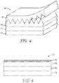
- FIG. 1 illustrates a perspective view of an exemplary structured surface film described herein 10 having a surface-structured pattern.
- the structured surface has peak to valley measurements of less than 2500 micrometers (preferably less than 250 micrometers, or even less than 100 micrometers).
- the portion of the structured surface film beneath the structured surface sometimes referred to as the "land" area, is preferably at least as thick as the peak to valley measurement of the structured surface.
- the substrate has a second major surface generally opposed to the first major surface and the surface-structured silicone-based material described herein on at least a portion of the second major surface.
- the substrate is a foam.
- the article is an adhesive article, wherein the silicone-based material described herein that is a pressure sensitive adhesive adhered to at least a portion of the first major surface of the substrate.
- FIG. 2 illustrates a perspective view of an exemplary structured surface adhesive film described herein 20 having structured surface adhesive 21 attached to substrate layer 22.
- the cross-linked material is non-tacky.
- substrates include at least one of a polymeric film, a polymeric sheet, a molded polymeric part, a metal (including a metal surface) (e.g., vapor deposited metals)) such as aluminum or stainless steel, paper, an ultraviolet (UV) mirror, infrared (IR) mirror, a UV stable substrate, a glass (e.g., soda-lime glass, low-iron glass, borosilicate glass, or quartz (fused silica)) substrate, a portion (e.g., hood, door, roof, side panel, trunk, or bumper) of a car, a portion (e.g., wing or fuselage) of a plane, a portion (e.g., roof or side) of a train, a wind turbine blade (e.g., any exterior portion of a turbine blade including the leading edge of the blade), a solar photovoltaic module (including a flexible photovoltaic module and a concentrating photovoltaic module), a solar thermal panel, a boat
- the substrates are transparent (i.e., transmit at least 85% of incident light in at least a [portion of the visible spectrum (400-700 nm wavelength).
- Transparent substrates may be colored or colorless.
- polymeric substrates examples include polyester (e.g., polyethylene terephthalate, polybutylene terephthalate), cyclic olefin co-polymer (COC), fluoropolymers (e.g., ethylene tetrafluorethylene, polyvinylidene fluoride, THV), polycarbonate, allyldiglycolcarbonate, polyacrylates, such as polymethylmethacrylate, polystyrene, polysulfone, polyethersulfone, homo-epoxy polymers, epoxy addition polymers with polydiamines, polydithiols, polyethylene copolymers, fluorinated surfaces, cellulose esters (e.g., acetate and butyrate).
- polyester e.g., polyethylene terephthalate, polybutylene terephthalate
- COC cyclic olefin co-polymer
- fluoropolymers e.g., ethylene tetrafluorethylene
- the substrate is flexible and made from polyesters (e.g., polyethylene terephthalate (PET)), cyclic olefin co-polymer (COC), polyolefins (e.g., PP (polypropylene), PE (polyethylene) and PVC (polyvinyl chloride) are particularly preferred.
- PET polyethylene terephthalate
- COC cyclic olefin co-polymer
- polyolefins e.g., PP (polypropylene), PE (polyethylene) and PVC (polyvinyl chloride) are particularly preferred.
- the substrate can be formed into a film using conventional filmmaking techniques such as extrusion of the substrate resin into a film and optional uniaxial or biaxial orientation of the extruded film.
- UV mirrors are known in the art and include a multilayer optical film constructed of alternating layers of a UV stabilized polyethylene terephthalate (PET) and a copolymer of methylmethacrylate and ethyl acrylate (co-PMMA) at thicknesses one quarter of the wavelength of the light they will reflect.
- PET polyethylene terephthalate
- co-PMMA copolymer of methylmethacrylate and ethyl acrylate
- IR mirrors are known in the art and include a multilayer optical film constructed of alternating layers of a UV stabilized polyethylene terephthalate (PET) and a copolymer of methylmethacrylate and ethyl acrylate (co-PMMA) at thicknesses one quarter of the wavelength of the light they will reflect.
- PET polyethylene terephthalate
- co-PMMA copolymer of methylmethacrylate and ethyl acrylate
- UV stable substrates include a film or part made from a polymer that generally maintains its optical and mechanical properties during outdoor exposure to sunlight and the elements for a period of at least 10 years either through the addition of UV absorbers, anti-oxidants and hindered amine light stabilizers and/or through the polymer's intrinsic weatherability (e.g., fluoropolymers).
- Solar photovoltaic modules are known in the art, and refer to the glass front surface of a module for rigid photovoltaic modules (e.g., crystalline silicon modules).
- the front surface substrate is generally a UV stable polymer film (e.g., ethylene tetrafluoroethylene).
- Solar thermal modules are known in the art and capture thermal energy by collecting the suns energy and heating a fluid. Solar thermal modules are similar to photovoltaic modules in that they are generally rigid and have a glass front surface.
- Reinforcing scrims are known in the art and include woven or non-woven fabric, that when impregnated with a resin and cured, provide improved dimensional stability and tensile properties by decreasing elongation and increasing strength of the resulting composite.
- Textiles are known in the art and include directionally flexible materials made of a network of natural or artificial fibers which are often used to make clothes, bags, furniture, tents, umbrellas, etc.
- Release liners are known in the art and are generally a paper or plastic based carrier web material, which is coated on one or two sides with a release agent, which provides a release effect against any type of a sticky material (e.g., an adhesive or a mastic).
- a sticky material e.g., an adhesive or a mastic
- Photobioreactors are known in the art and are bioreactors which incorporates some type of light source to provide photonic energy input into the reactor, generally used to cultivate microalgae. It is desirable to prevent accumulation of microalgae or other build-up on the inner walls of the photobioreactor therefore anti-fouling structures may be applied to the walls to prevent accumulation.
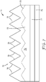
- FIG. 3 illustrates a perspective view of an exemplary structured surface film described herein 30 having structured surface 31 attached to substrate 33 with primer layer 32.
- primer coating is formed from a nanoparticle-containing coating composition that is coated and dried on a substrate surface.
- Other primer compositions or processes can be used to achieve acceptable adhesion between silicone and a substrate. Examples of such compositions include the use of reactive silane solutions or solutions of moisture cure/condensation reaction silicones, etc. Examples of commercially available primers include "3-6060 PRIME COAT" from Dow-Corning, Midland.
- silane primer is 3-aminopropyltriethoxysilane.
- the nanoparticle-containing primer coating composition includes an aqueous dispersion having a pH of less than 5 comprising silica nanoparticles having average particle diameters of up to 40 nanometers (preferably less than 20 nanometers), and an acid having a pK a of ⁇ 3.5 (preferably ⁇ 2.5, most preferably less than 1).
- a preferred is nanoparticle-containing primer comprises agglomerates of silica nanoparticles having average particle diameters of up to 40 nanometers, the agglomerates comprising a three-dimensional porous network of silica nanoparticles, and the silica nanoparticles are bonded to adjacent silica nanoparticles.
- These acidified aqueous silica nanoparticle primer coating compositions can be coated directly onto hydrophobic organic and inorganic substrates without either organic solvents or surfactants.
- the wetting property of these inorganic nanoparticle aqueous dispersions on hydrophobic surfaces e.g., polyethylene terephthalate (PET) or polycarbonate (PC) is a function of the pH of the dispersions and the pK a of the acid).
- PET polyethylene terephthalate
- PC polycarbonate
- the silica nanoparticles used in this primer composition are dispersions of submicron size silica nanoparticles in an aqueous or in a water/organic solvent mixture.
- the silica nanoparticles have an average primary particle diameter of up to 40 nanometers, preferably less than 20 nanometers, and more preferably less than 10 nanometers.
- the average particle size may be determined using transmission electron microscopy.
- the nanosilica described in this disclosure may be spherical or nonspherical.
- the silica nanoparticles are preferably not surface modified.
- the smaller nanoparticles (i.e., those up to 20 nanometers), generally provide better primer coatings, when acidified, without the need for additives (e.g., tetraalkoxysilanes, surfactants, and organic solvents).
- the nanoparticles generally have a surface area greater than 150 m 2 /g (in some embodiments, greater than 200, 300, or even greater than 400 m 2 /g).
- the particles preferably have narrow particle size distributions, that is, a polydispersity (i.e., particle size distribution) up to 2, preferably up to 1.5. If desired, larger silica particles may be added, in limited amounts that do not deleteriously decrease the coatability of the composition on a selected substrate, and do not reduce the transmissivity and/or the hydrophilicity.
- silica sols in aqueous media are well known in the art and available commercially.
- Silica sols in water or water-alcohol solutions are available, for example, under the trade designations "LUDOX” from E.I. duPont de Nemours and Co., Inc., Wilmington, DE; "NYACOL” from Nyacol Co., Ashland, MA; and "NALCO” from Ondea Nalco Chemical Co., Oak Brook, IL.
- One useful silica sol is NALCO 2326 available as a silica sol with mean particle size of 5 nanometers, pH 10.5, and solid content 15% by weight.
- silica nanoparticles include "NALCO 1115" and "NALCO 1130,” commercially available from NALCO Chemical Co., "REMASOL SP30,” commercially available from Remet Corp., Utica, NY, and “LUDOX SM,” commercially available from E.I. Du Pont de Nemours Co., Inc., and "SNOWTEX ST-OUP”, “SNOWTEX ST-UP”, and “SNOWTEX ST-PS-S” from Nissan Chemical Co., Houston, TX.
- Non-aqueous silica sols may also be used and are silica sol dispersions wherein the liquid phase is an organic solvent, or an aqueous organic solvent.
- the silica sol is chosen so that its liquid phase is typically aqueous or an aqueous organic solvent. It has been observed that sodium stabilized silica nanoparticles should first be acidified prior to dilution with an organic solvent (e.g., ethanol). Dilution prior to acidification may yield poor or non-uniform coatings. Ammonium stabilized silica nanoparticles may generally be diluted and acidified in any order.
- the primer coating composition contains an acid or combination of acids, each having a pK a (H 2 O) of ⁇ 3.5, preferably ⁇ 2.5, most preferably less than 1.
- Useful acids include both organic and inorganic acids and may be exemplified by oxalic acid, citric acid, H 2 SO 3 , H 3 PO 4 , CF 3 CO 2 H, HC1, HBr, HI, HBrO 3 , HNO 3 , HClO 4 , H 2 SO 4 , CH 3 SO 3 H, CF 3 SO 3 H, and CF 3 CO 2 H.
- Most preferred acids include HC1, HNO 3 , H 2 SO 4 , and H 3 PO 4 .
- a mixture of acids comprising those having a pK a ⁇ 3.5 (preferably ⁇ 2.5, most preferably less than 1), optionally with minor amounts of other acids having pK a 's > 0.
- weaker acids having a pK a of >4 e.g., acetic acid
- primer coating compositions with weaker acids typically bead up on the surface of a substrate.
- the primer coating composition generally contains sufficient acid to provide a pH of less than 5, preferably less than 4, most preferably less than 3. In some embodiments, it has been found that the pH of the coating composition can be adjusted to pH 5-6 after reducing the pH to substantially less than 5. This allows one to coat pH-sensitive substrates.
- Tetraalkoxy coupling agents particularly tetraalkoxysilanes (e.g., tetraethylorthosilicate (TEOS)), and oligomeric forms of tetraalkoxysilane (e.g., alkyl polysilicates (e.g., poly(diethoxysiloxane))), may also be useful to improve binding between silica nanoparticles.
- TEOS tetraethylorthosilicate
- alkyl polysilicates e.g., poly(diethoxysiloxane)
- the optimal amount of coupling agent is determined experimentally and is dependent on the coupling agent's identity, molecular weight and refractive index.
- the coupling agent(s), when present, are typically added to the composition at levels of 0.1 to 50 percent by weight (wt-%) of the silica nanoparticle concentration, and more preferably 1 to 15 percent by weight of the silica nanoparticles.
- the primer typically provides the surface coated thereon with a continuous network of silica nanoparticles agglomerates.
- the particles preferably have an average primary particle size of below 40 nanometers.
- the average particle size may be determined using transmission electron microscopy.
- continuous refers to covering the surface of the substrate with virtually no discontinuities or gaps in the areas where the gelled network is applied.
- network refers to an aggregation or agglomeration of nanoparticles linked together to form a porous three-dimensional network.
- primary particle size refers to the average size of unagglomerated single particles of silica.
- porous refers to the presence of voids between the silica nanoparticles created when the nanoparticles form a continuous coating.
- the network has a porosity of 25 to 45 volume percent, more preferably 30 to 40 volume percent, when dried. In some embodiments the porosity may be higher. Porosity may be calculated from the refractive index of the coating according to published procedures such as in W. L. Bragg, A. B. Pippard, Acta Crystallographica, volume 6, page 865 (1953 ).
- a primer composition onto a hydrophobic substrate from an aqueous system it may be desirable to increase the surface energy of the substrate and/or reduce the surface tension of the coating composition.
- the surface energy may be increased by oxidizing the substrate surface prior to coating using corona discharge or flame treatment methods. These methods may also improve adhesion of the coating to the substrate.
- Other methods capable of increasing the surface energy of the article include the use of primers such as thin coatings of polyvinylidene chloride (PVDC).
- PVDC polyvinylidene chloride
- the surface tension of the coating composition may be decreased by addition of lower alcohols (C 1 to C 8 ).
- a wetting agent which is typically a surfactant
- surfactant as used herein describes molecules comprising hydrophilic (polar) and hydrophobic (non-polar) regions on the same molecule which are capable of reducing the surface tension of the coating solution.
- Useful surfactants may include those disclosed in U.S. Pat. No. 6,040,053 (Scholz et al. ).
- most surfactants comprise less than 0.1 percent by weight of the coating composition, preferably 0.003 to 0.05 percent by weight.
- Anionic surfactants in the primer coating composition are preferred when added to improve the uniformity of the resulting coatings.
- Useful anionic surfactants include those with molecular structures comprising (1) at least one hydrophobic moiety, such as C 6 -C 20 alkyl, alkylaryl, and/or alkenyl groups, (2) at least one anionic group, such as sulfate, sulfonate, phosphate, polyoxyethylene sulfate, polyoxyethylene sulfonate, polyoxyethylene phosphate, and the like, and/or (3) the salts of such anionic groups, wherein said salts include alkali metal salts, ammonium salts, tertiary amino salts, and the like.
- useful anionic surfactants include sodium lauryl sulfate (available, for example, under the trade designations "TEXAPON L-100" from Henkel Inc., Wilmington, DE; and “POLYSTEP B-3” from Stepan Chemical Co, Northfield, IL); sodium lauryl ether sulfate (available, for example, under the trade designation “POLYSTEP B-12” from Stepan Chemical Co., Northfield, IL); ammonium lauryl sulfate (available, for example, under the trade designation "STANDAPOL A” from Henkel Inc., Wilmington, DE); and sodium dodecylbenzenesulfonate (available, for example, under the trade designation "SIPONATE DS-10" from Rhone-Poulenc, Inc., Cranberry, NJ).
- a primer does not include a surfactant or when improved coating uniformity is desirable, it may be beneficial to add another wetting agent in order to ensure uniform coating of a surface from an aqueous or hydroalcoholic solution.
- useful wetting agents include polyethoxylated alkyl alcohols (available, for example, under the trade designations "BRIJ 30" and “BRIJ 35 from ICI Americas, Inc.; and “TERGITOL TMN-6" SPECIALTY SURFACTANT” from Union Carbide Chemical and Plastics Co.), polyethoxylated alkylphenols (available, for example, under the trade designations, "TRITON X-100" from Union Carbide Chemical and Plastics Co., "ICONOL NP-70” from BASF Corp., Florham Park, NJ); and polyethylene glycol/polypropylene glycol block copolymer (available, for example, under the trade designations "TETRONIC 1502 BLOCK COPOLYMER SURFACTANT", "TETRONIC 908 BLO
- the wetting agent is used in amounts of less than 0.1 percent by weight of the coating composition, preferably 0.003 to 0.05 percent by weight of the coating composition depending on the amount of silica nanoparticles. Rinsing or steeping the coated article in water may be desirable to remove excess surfactant or wetting agent.
- Primers are preferably coated on a surface using conventional techniques, such as bar, roll, curtain, rotogravure, spray, or dip coating techniques.
- the preferred methods include bar and roll coating, or air knife coating to adjust thickness.
- Other methods capable of increasing the surface energy of the article include the use of primers such as polyvinylidene chloride (PVDC).
- the primer is preferably applied in uniform average thicknesses varying by less than 200 angstroms, and more preferably by less than 100 angstroms, in order to avoid visible interference color variations in the coating.
- the optimal average dry coating thickness is dependent upon the particular primer coating composition, but in general the average thickness of the coating is 100 angstroms to 10,000 angstroms, preferably 500 angstroms to 2500 angstroms, more preferably 750 angstroms to 2000 angstroms, and even more preferably 1000 angstroms to 1500 angstroms, as measured using an ellipsometer such as a Gaertner Scientific Corp Model No. L115C. It should be noted, however, that while the average coating thickness is preferably uniform, the actual coating thickness can vary considerably from one particular point on the coating to another.
- Primers can be coated on both sides of a substrate if desired. Alternatively, the primers may be coated on one side of the substrate.
- the primed article is typically dried at temperatures in a range from 20°C to 150°C in a recirculating oven.
- An inert gas may be circulated.
- the temperature may be increased further to speed the drying process, but care should be exercised to avoid damage to the substrate.
- the cure temperature can be above 200°C.
- the coating comprises preferably from 60 to 95 percent by weight (more preferably from 70 to 92 percent by weight) of silica nanoparticles (typically agglomerated), from 0.1 to 20 percent by weight (more preferably from 10 to 25 percent by weight) tetraalkoxysilanes and optionally 0 to 5 percent by weight (more preferably from 0.5 to 2 percent by weight) surfactant, and optionally up to 5 percent by weight (preferably 0.1 to 2 percent by weight) wetting agent.
- silica nanoparticles typically agglomerated
- 0.1 to 20 percent by weight more preferably from 10 to 25 percent by weight
- tetraalkoxysilanes optionally 0 to 5 percent by weight (more preferably from 0.5 to 2 percent by weight) surfactant, and optionally up to 5 percent by weight (preferably 0.1 to 2 percent by weight) wetting agent.
- the procedures for making a structured silicone utilize a tool that will impart the negative structure in the silicone surface before the silicone is cross-linked using electron beam radiation.
- the tooling can be of a variety of forms and materials. Commonly the form of the tooling will either be a sheet, roll, belt or roll of film. Tooling is generally constructed of material that fall either into the category of metal or polymer but could potentially include ceramic or other suitable material.
- the metal is generally diamond-machined, embossed, knurled, sandblasted, etc. to form the surface structure.
- the structured polymer surface is generally formed by extrusion replication where a thermoplastic resin such as polypropylene is extruded using standard extrusion equipment and fed through a die and into a nip with a machined metal tool roll and a rubber roll. The molten polymer is quenched while in contact with a tool surface which then releases from the tool roll and is wound on a roll. Additional polymer tooling can be made by UV-curing acrylate functional resins against a tool followed by removal of the cross-linked structured film from the tool.
- a thermoplastic resin such as polypropylene
- polystyrene polyethylene
- polyethylene terephthalate polyethylene terephthalate
- ethylene/octene ethylene/hexene
- other ethylene copolymers propylene/ethylene
- propylene copolymers of lower modulus UV-curable acrylates
- poly(methyl methacrylate) polycarbonate
- polystyrene polystyrene acrylonitrile
- polyurethane polyurethane or other suitable materials.
- the non-cross-linked silicone material is brought into intimate contact with the tooling surface by way of direct coating silicone fluid or gum against the tooling surface.
- Other options include pressing the silicone material between the tooling and a substrate using nip rolls or a platen press.
- the silicone must be cross-linked while in contact with the tool. Therefore the silicone passes through an electron beam unit while still in contact with the tool.
- the electron beam radiation can penetrate from either the tooling film side or the silicone side.
- the electron beam may pass through the tooling side or the substrate side depending on the thickness and density of the tooling and the substrate.
- exemplary structured surface tooling film 41 may be removed to expose final structured surface 42 attached to substrate 44 with primer 43.
- the structured surface tooling film may be removed manually or with a machine.
- FIG. 5 illustrates a schematic view of exemplary structured surface film 50 having structured surface 51 attached to substrate 54 with primer layer 53 and adhesive layer 52.
- the higher cross-link density of the silicone elastomer surface results in an increased resistance to dirt and dust particle pick-up, as well as an increase in the abrasion resistance.
- the treatment e.g., conventional e-beam radiation cross-linking techniques
- the structured surface may be entirely cross-linked to about the higher silicone elastomer cross-link density.
- exemplary transparent structured surface film described herein 60 comprises structured film substrate 62 that has a major structured face 64 with structured surfaces (e.g., in the form of prismatic riblets 66). Each structured surface 66 has tip angle ⁇ and structured surface 68 that is exposed.
- Film 60 further comprises base portion 63 from which structured surfaces 66 extend.
- Base portion 63 can be an integrally formed part of structures 66 as illustrated, or a separate layer as indicated by dashed line 61.
- Structured film substrate 62 comprises a cross-linked silicone elastomeric material. The silicone elastomeric material is formed by electron beam irradiation of silicone fluid or gum.
- Structured face 64 is exposed to an additional cross-linking treatment (e.g., e-beam radiation or heat energy) such that each structured surface 68 has a silicone elastomer cross-link density that is higher than a core or otherwise remainder 62 of structured film substrate 62.
- the depth D of the higher cross-link density depends on the acceleration voltage and/or duration of the additional cross-linking treatment.
- the higher cross-link density of structured surface 68 results in an increased resistance to dirt and dust particle pick-up, as well as an increase in the abrasion resistance of silicone elastomer surface 68.
- support backing 65 has primer layer 67 bonded to structured film substrate 62.
- Support backing 65 can comprise a polymeric material or an inorganic glass or other transparent ceramic material.
- Exemplary polymeric materials may include at least one or a combination of a polymethyl methacrylate (PMMA) film, polyvinylidene fluoride (PVDF) film, polyethylene terephthalate (PET) film, primed PET film, polycarbonate film, cross-linked polyurethane film, acrylate film, or fluorinated ethylene-propylene (FEP) film.
- PMMA polymethyl methacrylate
- PVDF polyvinylidene fluoride
- PET polyethylene terephthalate
- FEP fluorinated ethylene-propylene
- the other transparent ceramic material may be, for example, quartz crystal.
- Transparent nonwoven or woven fiber materials, or chopped transparent fibers may also be used to form support backing 65. Such fiber materials may also be disposed in the silicone elastomeric material forming structured film 60
- Transparent support backing 65 can also be chosen so as to dissipate static electricity.
- the support backing can comprise one or more polymeric materials that enable support backing 65 to dissipate static electricity.
- transparent support backing 65 may also comprise an inherently static dissipative polymer (available, for example, under the trade designations "STATRITE X5091 POLYURETHANE” or “STATRITE M809 POLYMETHYL METHACRYLATE” from Lubrizol Corp., Wickliffe, OH)
- static dissipative salts available, for example, under the trade designation "FC4400" from 3M Company, St. Paul, MN
- FC4400 3M Company, St. Paul, MN
- Support backing 65 can also be comprised of multiple layers.
- major structured face 74 is exposed to additional cross-linking such that all of the silicone elastomeric material of each of structured surfaces 76 has a silicone elastomer cross-link density about as high as that of structured surface 78, with remainder 72 of film 70 having a lower silicone elastomer cross-link density than that of each of structured surfaces 76.
- Dashed line 73 separates the higher cross-link density portion of film 70 from the lower cross-link density portion. It can be desirable for film 70, or any other structured surface film according to the invention, to be used in combination with optional support backing 75. With such an embodiment, support backing 75 has primer layer 77 bonded to structured film substrate 75.
- the present disclosure also provides an article comprising at least first and second layers (in some embodiments a third, or more layers) with at least one layer comprising a surface-structured, cross-linked silicone-based material described therein.
- the layers each have a degree of cross-linking of the silicone-based material.
- first, second, and third layers each have a degree of cross-linking of the silicone-based material, wherein the degree of cross-linking of the silicone-based material for the first layer is greater than the degree of cross-linking of the silicone-based material for the second layer, and wherein the degree of cross-linking of the silicone-based material for the second layer is greater than the degree of cross-linking of the silicone-based material for the third layer.
- each layer has a different composition.
- These articles can provide, for example, a highly cross-linked surface that is non-tacky (e.g., dirt pick-up resistant), on a top of a elastomeric middle layer, on top of a third to cross-linked layer that exhibits pressure sensitive adhesive-like properties.
- Fresnel lenses are lenses of large aperture and short focal length without the weight and volume of conventional lenses produced by breaking the lens into a set of concentric annular sections known as "Fresnel zones”. Fresnel lenses are commonly used for concentrating sunlight onto solar photovoltaic or solar thermal modules although they have been and are used for many other applications. Fresnel lenses are often made out of polymethyl methacrylate (PMMA) and polycarbonate. "Silicone on glass” Fresnel lenses are more recent and comprise a structured silicone on glass. These Fresnel lenses offer the potential for increased durability and weatherability.
- the "silicone on glass" Fresnel lens may be improved by the following process.
- the glass may be primed on one side using the nano-silica solution described herein and optionally coated on the opposite sun side of the glass with nano-silica solution described herein to reduce reflection and improve light capture.
- the primer may be baked to improve adhesion.
- a blend of non-functional polydimethylsiloxane (PDMS) fluid and vinyl-functional PDMS fluid can be coated onto a Fresnel tooling surface so that the features are fully filled and a smooth PDMS blend surface results.
- the filled tooling can then be passed through an e-beam process which cross-links the PDMS fluid blend.
- PDMS polydimethylsiloxane
- a UV initiated, Pt catalyzed, addition cure silicone fluid tie layer such as described, for example, in Example 11, can optionally be applied in a very thin layer, to minimize cost, to the primed glass surface.
- This solution may be applied onto the glass with various techniques, such as roll coating, notch-bar coating, and screen-printing. The thickness of this layer can vary, although the cure dynamics are to be taken into account so that it does not cure prior to lamination but still cures quickly after lamination and UV exposure.
- the silicone filled tooling film Prior to curing of the silicone tie-layer, is laminated to the primed glass. This lamination step may involve a rolling bank of silicone to form at the lamination site. Registration of the tooling film pattern to the glass edges may need to be tightly controlled.
- the construction can then be irradiated with UV radiation from a standard H bulb or black light to initiate the silicone tie-layer cross-linking.
- UV radiation from a standard H bulb or black light
- the Fresnel tooling can be removed leaving the e-beam cross-linked silicone Fresnel adhered to the glass sheet.
- an e-beam cross-linked silicone Fresnel lens can be made directly onto a primed film without the use of a separate silicone tie-layer.
- a poly dimethylsiloxane (PDMS) gum may be pressed between a polymethylmethacrylate (PMMA) Fresnel tool and sheet of polyethylene terephthalate (PET) primed with the nano-silica solution described herein.
- PMMA polymethylmethacrylate
- PET polyethylene terephthalate
- This construction may be passed through an e-beam process so that the radiation passes first through the PET surface.
- the PMMA tool may be removed leaving the e-beam cross-linked silicone Fresnel lens attached to the primed PET surface.
- a microstructured urethane acrylate tool film was made using a formulation consisting of 55.3% by weight aliphatic urethane acrylate (obtained under the trade designation "CN991" from Sartomer USA, Exton, PA), 31.6% by weight polyester acrylate oligomer (obtained under the trade designation “CN2303” from Sartomer USA), 10% by weight tetrahydrofuryl acrylate (obtained under the trade designation "SR285" from Sartomer USA), 5% by weight acrylate functional polyhedral oligomeric silsesquioxane (obtained under the trade designation "ACRYLO POSS” from Hybrid Plastics, Inc., Hattiesburg, MS), 2% by weight hydroxyphenyl benzotriazole UV absorber (obtained under the trade designation "TINUVIN 928” from Ciba Specialty Chemicals, Inc., Tarrytown, NY), 2% by weight hindered amine light stabilizer (obtained under the trade designation "TIN
- the urethane acrylate was coated on to 35.6 cm (14 inch) wide pre-primed polyethylene terephthalate (PET) (obtained under the trade designation "MELINEX 618" from DuPont Teijin Films, Chester, VA).
- PET polyethylene terephthalate
- the urethane acrylate was UV cured through the PET film while in contact with a machined metal roll with prismatic grooves with a 24 micrometer pitch and 90 degree tip angle.
- the resulting PET film with urethane acrylate structured surface was wound on to a roll.
- the silicone fluid used was a silanol terminated polydimethylsiloxane with a kinematic viscosity of 18,000 centistokes (obtained under the trade designation "DMS-S42” from Gelest, Inc, Morrisville, PA).
- the substrate film was a 33 cm (13 inch) wide, 25 micrometer thick PET (available under the trade designation "MYLAR Polyester from DuPont Teijin Films, Chester, VA)) primed with a 2 micrometer wet coating of solvent-borne silicone primer (obtained under the trade designation "SS4120” from Momentive Performance Materials, Inc., Waterford, NY) and then dried at 71°C (160°F)-93°C (200°F).
- the silicone fluid was applied to the solvent-borne silicone primer ("SS4120") primed PET substrate using a 25.4 cm (10 inch) wide coating die and a gear pump (obtained from Zenith Pumps, Monroe, NC; Model # 6152789-003) prior to entering a nip roll station.
- the urethane acrylate tooling film was introduced at the nip station, where the structured surface of the tooling film was brought into intimate contact with the silicone fluid.
- the film construction passed into an electron beam irradiation unit where the construction received a dose of 30 MRad at an acceleration voltage of 200 keV and a line speed of 15.2 m/min (50 feet/min).
- the electron beam unit was a broadband curtain type electron beam processor (obtained from Energy Sciences, Inc., Wilmington MA). After exiting the electron beam unit the film construction was wound on a roll. At this point the silicone fluid was cross-linked and retains the shape it held while passing through the electron beam unit. The urethane acrylate tooling film was pulled away leaving a reverse image formed in the silicone attached to the solvent-borne silicone primer ("SS4120”) primed PET substrate.
- SS4120 solvent-borne silicone primer
- a microstructured polypropylene film was made using an extrusion replication process.
- Polypropylene obtained under the trade designation "FINA 7825” from Total Petrochemicals USA, Inc. Houston, TX
- FINA 7825 from Total Petrochemicals USA, Inc. Houston, TX
- the polypropylene extrudate film quenches while against the machined roll forming a linear prism surfaced film, which was then wound into a roll.
- a roll of 30.5 cm (12 inch) wide PET film was primed with an adhesion promoting nano-silica primer.
- the nano-silica primer consists of a 5 % by weight blend of a 70:30 weight ratio of a first colloidal silica (obtained under the trade designation "NALCO 1115 COLLOIDAL SILICA” from Nalco Chemical Company, Naperville, IL) and a second colloidal silica (obtained under the trade designation "NALCO 1050 COLLOIDAL SILICA” from Nalco Chemical Company) in H 2 O, brought to a pH of 2.5-2.0 with HNO 3 .
- the primer was coated onto the PET film at a thickness of about 100 nanometers, run through an oven at 21°C (70°F)-107°C (225°F) and then wound on a roll.
- a non-functional silicone gum (obtained under the trade designation "EL POLYMER NA” available from Wacker Chemical Corp, Adrian, MI) was extruded from a 15.2 cm (6 inch) wide film extrusion die at 191°C (375°F) using a 5.1 cm (2 inch) diameter extruder (obtained under the trade designation "BONNOT EXTRUDER” from The Bonnot Company, Uniontown, OH). The gum was extruded directly into a nip roll casting station consisting of a metal chill roll and a rubber roll.
- Both the polypropylene tooling film and the nano-silica primed PET film were introduced into the nip while the silicone gum was extruded between them so that the polypropylene tooling film structures made intimate contact with the top surface of the extruded silicone gum and the nano-silica primed surface of the PET film was in intimate contact with the bottom surface of the extruded silicone gum.
- This film construction was then wound in to a roll. Sections of the film constructions 0.9 meter (3 feet) long were unwound and taped onto a carrier web that passed through an electron beam at an acceleration voltage of 300 keV and a dose of 3 MRads.
- the electron beam unit was a broadband curtain type electron beam processor (obtained from PCT Engineered Systems, LLC, Davenport, IA). After irradiation, the polypropylene tooling film was removed leaving the reverse image in the surface of the cross-linked silicone film attached to the nano-silica primed PET film.
- the silicone and tooling films were analyzed using a digital microscope which showed excellent replication of the tooling film surface in the cross-linked silicone gum film.
- a microstructured silicone film on a flexible substrate could be made using a structured metal tool roll within an electron beam unit.
- a metal conductive chill roll within an electron beam unit could be replaced with a chill roll whose surface was machined to a specific pattern.
- a nano-silica primed PET film could be coated with a silicone fluid so that as it passes into the electron beam the coated silicone surface makes intimate contact with the machined chill roll. While the silicone is in contact with the machined chill roll the electron radiation would penetrate the PET substrate and the silicone resulting in a cross-linked silicone film that would release from the machined tool roll when it reaches a strip-off roll after the irradiation zone. After the silicone film is stripped from the machined tool roll it would pass out of the electron beam unit where it would be wound in to a roll, retaining microstructured surface.
- a microstructured silicone film on a flexible substrate could be made using a structured metal belt tool passing through an electron beam unit.
- a metal belt with a surface machined to a specific pattern could be designed to pass through an electron beam unit.
- a nip roll could be designed to contact the belt tool on the inlet side of the electron beam unit allowing extrusion directly into the nip and also a point to introduce a primed substrate film.
- Silicone gum could be extruded from a film extrusion die directly into the nip formed between the nip roll and the metal belt tool.
- a primed film substrate could be introduced in the nip as well.
- the electron radiation would penetrate the film substrate and the silicone resulting in a cross-linked silicone film that would release from the machined belt tool when it reaches a strip-off roll after the irradiation zone outside of the electron beam unit. After the silicone film is stripped from the machined belt tool it would be wound in to a roll, retaining microstructured surface.
- a microstructured silicone surface was formed on a rigid glass substrate using a structured polypropylene film as a tool, a non-functional polydimethylsiloxane gum and a nano-silica primed glass substrate.
- the microstructured polypropylene film was made using an extrusion replication process.
- Polypropylene (“FINA 7825”) was extruded through a film extrusion die into a nip roll casting station consisting of one rubber roll and a second machined roll with linear prismatic grooves having 54 degree peaks and valley with a 50 micrometer pitch.
- the polypropylene extrudate quenches while against the machined roll forming a liner prism surfaced film, which was then wound into a roll.
- the nano-silica primer consists of a 5 % by weight blend of a 70:30 ratio of a first colloidal silica ("NALCO 1115 COLLOIDAL SILICA”) and a second colloidal silica (“NALCO 1050 colloidal SILICA) in H 2 O, brought to a pH of 2.5-2.0 with HNO 3 .
- a thin (about 100 nanometers) even coating of the primer was applied to a 7.6 cm (3 inch) by 5.1 cm (2 inch) glass slide by wiping the surface with a small wipe (obtained under the trade designation "KIMTECH” from Kimberly-Clark, Roswell, GA) dampened with the nano-silica primer solution.
- the primer was allowed to dry at room temperature.
- a 0.5 gram portion of a non-functional silicone gum (“EL POLYMER NA”) was weighed and formed into a round ball.
- the ball of silicone gum was placed on the primed surface of the glass slide.
- a 7.6 cm (3 inch) by 5.1 cm (2 inch) piece of the polypropylene tooling film was placed on top of the silicone ball with the tooling film surface structure pressing into the silicone gum.
- the silicone gum was pressed to a thickness of 75 micrometer between the polypropylene tooling film and the primed glass slide using an unheated platen press using a pressure of 27.6 MPa (4000 psi).
- the glass slide, silicone and tooling film construction was taped to a carrier web and passed through an electron beam at an acceleration voltage of 300 keV and a dose of 3 MRads.
- the E-beam unit was a broadband curtain type electron beam processor (obtained from PCT Engineered Systems, LLC).
- the polypropylene tooling film was removed leaving the reverse image in the surface of the cross-linked silicone attached to the nano-silica primed glass. During the irradiation color centers develop within the glass matrix resulting in a brown tint within the glass.
- the silicone coated glass slide was placed in a 250°C oven for 3 hours to remove the majority of the color returning the glass to the original clear state.
- the silicone and tooling films were analyzed using a digital microscope which showed excellent replication of the tooling film surface in the cross-linked silicone gum.
- a microstructured silicone pressure sensitive adhesive (PSA) film could be made by using a microstructured release liner and a silicone formulation containing an MQ tackifier resin and a primed backing film.
- the microstructured release liner could be made by using an extrusion replication process followed by a plasma fluorine deposition process to apply a thin release layer on the surface.
- Polypropylene e.g., "FINA 7825”
- FINA 7825 a film extrusion die into a nip roll casting station consisting of one rubber roll and a machined roll with linear prismatic grooves having 54 degree peaks and valleys with a 50 micrometer pitch.
- the polypropylene extrudate film quenches while against the machined roll forming a prism surfaced liner film, which could then wound into a roll.
- the surface-structured polypropylene liner could then pass through a plasma fluorination process to apply a thin release surface on the structured liner.
- a non-functional silicone gum e.g., "EL POLYMER NA” could be blended with 10-60% MQ tackifier resin (available, for example, under the trade designation SQO-299 from Gelest, Inc., Morrisville, PA) to make a PSA formulation.
- the nano-silica primer consists of a 5% by weight blend of a 70:30 ratio of a first colloidal silica ("NALCO 1115 COLLOIDAL SILICA”) and a second colloidal silica (“NALCO 1050 COLLOIDAL SILICA”) in H 2 O, brought to a pH of 2.5-2.0 with HNO 3 .
- the primer can be coated (e.g., at a thickness of about 100 nanometers) onto an adhesive backing material of choice.
- the PSA formulation could be extruded from a film extrusion die using an extruder ("BONNOT EXTRUDER").
- the PSA could be extruded directly into a nip roll casting station consisting of a metal chill roll and a rubber roll.
- Both the fluorinated structured release liner and the nano-silica primed backing film could be introduced into the nip while the PSA film is extruded between them so that the release liner structures make intimate contact with the top surface of the extruded PSA and the nano-silica primed surface of the backing film makes intimate contact with the bottom surface of the extruded PSA.
- This film construction could then be passed through an electron beam at an acceleration voltage of 300 keV and a dose of 3 to 6 MRads.
- the structured fluorinated polypropylene release liner could be removed leaving the reverse image in the surface of the cross-linked silicone PSA film attached to the nano-silica primed backing film. The grooves will allow air to bleed along the channels and allow bubble free application of the silicone PSA film.
- any of the methods according, for example, to Examples 1-4 could be used to make a microstructured silicone film that could be used as a release liner for making structured PSAs.
- microstructured silicone films described in Examples 1-4 could substitute for the structured release liners described, for example, in U.S. Pat. No.3,301,741 (Henrickson et al. ) which reports using a microstructured film coated with a thin layer of release material for a release liner and then coating that film with a PSA formulation so that when the PSA is cross-linked it holds the microstructure when the release liner is removed.
- a variety of functional PSAs can be created depending on the pattern of original release liner such as air-bleed PSAs for bubble-free application.
- the surface-structured cross-linked silicone can be irradiated with low voltage electron beam(100-150kv) with a dosage of at least 20 megarads (more preferably, at least 30 megarads), to create higher cross-link density at the surface of the surface-structured cross-linked silicone.
- Example 8 Surface-structured cross-linked silicone as described in Example 8 is coated onto a UV mirror and then applied to a photovoltaic module.
- a UV reflective multilayer optical film can be made with first optical layers of a polyethylene terephthalate (PET) (PET1; available from DuPont, Wilmington, DE) and second optical layers of co-polymethyl (meth)acrylate (PMMA) (coPMMA1; available from Plaskolite, Inc., Columbus, OH), .
- PET1 polyethylene terephthalate
- PMMA co-polymethyl (meth)acrylate
- coPMMA1 available from Plaskolite, Inc., Columbus, OH
- the layer thickness profile (layer thickness values) of this UV reflector can be adjusted to be approximately a linear profile with the first (thinnest) optical layers adjusted to have about a 1 ⁇ 4 wave optical thickness (index times physical thickness) for 300 nm light and progressing to the thickest layers which can be adjusted to be about 1 ⁇ 4 wave thick optical thickness for 400 nm light.
- Layer thickness profiles of such films can be adjusted to provide for improved spectral characteristics using the axial rod apparatus disclosed in U.S. Pat. No. 6,783,349 (Neavin et al. ), combined with layer profile information obtainable by atomic force microscopic techniques.
- UV absorber masterbatch e.g., available under the trade designation "SUKANO TA07-07 MB” from Sukano Polymers Corp, Duncan, SC
- PET1 first optical layers
- non-optical protective skin layers made by blending 35wt% polyvinylidene (PVDF) (available under the trade designation “PVDF1008” from 3M Company) with 65 wt% PMMA(available under the trade designation "CP82” from Plaskolite, Inc.), having a thickness of 260 micrometers each can be coextruded on either side of the optical stack.
- 20 wt% of UV absorber masterbatch e.g., "SUKANO TA11-10 MB01
- UV absorber masterbatch e.g., "SUKANO TA11-10 MB01
- This multilayer coextruded melt stream can be cast onto a chilled roll at 5.4 meters per minute creating a multilayer cast web approximately 500 micrometers (20 mils) thick.
- the multilayer cast web can then be preheated for about 10 seconds at 95°C and biaxially oriented at a draw ratios of 3.5x3.7.
- the oriented multilayer film can be further heated at 225°C for 10 seconds to increase crystallinity of the PET layers.
- this UV stable surface-structured cross-linked silicone film is expected to increase power output by 4.5%.
- a "silicone on glass” Fresnel lens was made comprising an e-beam cured silicone.
- Low iron glass panels were cleaned with cleaner (obtained under the trade designation "ALCONOX” from Alconox, White Plains, NY) and stored in deionized water.
- the cleaned glass was removed from the water bath and dried with a stream of compressed air.
- a nano-silica primer was applied to a major surface of the clean glass.
- the aqueous nano-silica primer contained a 5% by weight blend in water of a 70:30 weight ratio of a first colloidal silica (obtained under the trade designation "NALCO 1115 COLLOIDAL SILICA” from Nalco Chemical Company, Naperville, IL) and a second colloidal silica (obtained under the trade designation "NALCO 1050 COLLOIDAL SILICA” from Nalco Chemical Company), brought to a pH of 2.0 with HNO 3 .
- the nano-silica primer was applied to a major surface of the glass panel by wiping the surface with a small wipe (obtained under the trade designation "KIMTECH” from Kimberley Clark, Irving, TX) dampened with the nano-silica primer solution. The primer was applied at a dry thickness of about 100 nanometers. The primer was allowed to dry at room temperature.
- a silicone blend was made containing 50 wt. % non-functional polydimethylsiloxane (PDMS) fluid (obtained under the trade designation “DMS-T43” from Gelest, Morrisville, PA) and 50 weight % of vinyl terminated silicone fluid (obtained under the trade designation "DMS-V42” from Gelest).
- the silicone blend was then coated into a microreplicated daylighting film (obtained under the trade designation "DLRP0022” from 3M Company, St. Paul, MN) using a notch bar coater set with a gap so that the tooling features were filled and a planar top surface resulted.
- the coated tooling film was passed open face through an e-beam process where it received a dose of 16 MRad through two passes at 8 MRad/pass at an acceleration voltage of 300 keV which fully cross-linked the silicone.
- the resulting construction was laminated to the primed glass using a thin layer of a clear thermal-cure silicone elastomer (obtained under the trade designation "SYLGARD 184" from Dow Corning Corporation, Midland, MI).
- the thermal-cure silicone elastomer (“SYLGARD 184”) was cured at 100°C for one hour. After the silicone elastomer (“SYLGARD 184”)-layer was cured, the tooling film was removed leaving the e-beam cured Fresnel structured silicone attached to the glass with the silicone elastomer (“SYLGARD 184”) tie-layer.
- a silicone blend was made containing 95 wt. % non-functional polydimethylsiloxane fluid (obtained under the trade designation "DMS-T41.2” from Gelest) and 5 weight % of vinyl terminated silicone fluid (obtained under the trade designation "DMS-V41” from Gelest).
- the silicone blend was then coated into a microreplicated daylighting film ("DLRP0022").
- the coated tooling film was passed open face through an e-beam process where it received a dose of 20 MRad through two passes at 10 MRad/pass at an acceleration voltage of 300 keV which fully cross-linked the silicone.
- a two-part photocurable silicone was prepared as follows.
- the two-part mixture was formulated to be mixed in a 1:1 ratio of Part A to Part B to make the photocurable silicone.
- Part A was prepared as follows. To a 22.7 liter (5 gallon) polyethylene pail (obtained from Consolidated Container Co. Ltd., Minneapolis, MN) was added 9.7 kg of a mixture of about 25% by weight vinyl MQ resin in a vinyl terminated polydimethylsiloxane polymer (obtained under the trade designation "VQM-135" from Gelest, Inc.), 5.23 kg of a vinyl terminated polydimethylsiloxane polymer (obtained under the trade designation "DMS-V22" from Gelest, Inc., Morrisville, PA), and 0.98 gram of trimethyl(methylcyclopentadienyl)platinum IV dissolved in 2 mL heptane (catalyst obtained from Strem Chemical Inc, Newburyport, MA). The resulting mixture was stirred using an overhead stirrer for 30 minutes until the mixture was homogeneous. The platinum catalyst concentration was designed to be 20 ppm platinum for the 2-part mixed formulation.
- Part B was prepared as follows. To a 22.7 liter (5 gallon) polyethylene pail was added 9.7 kg of a mixture of about 25% by weight vinyl MQ resin in a vinyl terminated polydimethylsiloxane polymer ("VQM-135"), 6.4 kg of a vinyl terminated polydimethylsiloxane polymer (“DMS-V22”), and 1.39 kg of a silicon hydride containing crosslinker (obtained under the trade designation "DOW CORNING SYL-OFF 7678 Crosslinker" (Lot# 0002623315 from Dow Corning Corporation). The resulting mixture was stirred using an overhead stirrer for 30 minutes until the mixture was homogeneous.
- VQM-135" vinyl terminated polydimethylsiloxane polymer
- DMS-V22 vinyl terminatedimethylsiloxane polymer
- silicon hydride containing crosslinker obtained under the trade designation "DOW CORNING SYL-OFF 7678 Crosslinker" (Lot# 000
- the "photocurable silicone tie layer” was coated onto a major surface of the glass prepared with the silica nanoparticle coating as described in Example 10.
- the filled tooling film was then laminated to the primed glass and partially cured via exposure to 350 nm UV lamps for 3 minutes through the glass side of the construction.
- the sample was then fully cured in an oven at 80°C for 10 minutes. After the thermal cure step the tooling film was removed leaving the e-beam cured Fresnel structured silicone attached to the glass with the photocurable silicone tie-layer.
Landscapes
- Chemical & Material Sciences (AREA)
- Organic Chemistry (AREA)
- Chemical Kinetics & Catalysis (AREA)
- Health & Medical Sciences (AREA)
- Engineering & Computer Science (AREA)
- Physics & Mathematics (AREA)
- Wood Science & Technology (AREA)
- Materials Engineering (AREA)
- Life Sciences & Earth Sciences (AREA)
- Medicinal Chemistry (AREA)
- Polymers & Plastics (AREA)
- General Chemical & Material Sciences (AREA)
- Toxicology (AREA)
- General Physics & Mathematics (AREA)
- Optics & Photonics (AREA)
- General Health & Medical Sciences (AREA)
- Plasma & Fusion (AREA)
- Laminated Bodies (AREA)
- Adhesives Or Adhesive Processes (AREA)
- Paints Or Removers (AREA)
- Treatments Of Macromolecular Shaped Articles (AREA)
Claims (13)
- Procédé de fabrication d'un matériau à base de silicone réticulé, structuré en surface, le procédé comprenant :la fourniture d'un matériau à base de silicone structuré en surface comprenant un adhésif sensible à la pression à base de silicone, dans lequel le matériau structuré en surface est essentiellement dépourvu de catalyseurs et d'initiateurs pour le durcissement du matériau à base de silicone de telle sorte qu'une quantité de catalyseur ou d'initiateur ne réduit pas le temps de durcissement de la composition d'au moins 10 % par rapport au temps de durcissement pour la même composition en l'absence de ce catalyseur ou initiateur ;l'exposition du matériau à base de silicone structuré en surface à un faisceau d'électrons pour réticuler le matériau à base de silicone pour fournir le matériau à base de silicone réticulé, structuré en surface ; dans lequel la fourniture du matériau à base de silicone structuré en surface comprend l'une parmi :1) la fourniture d'un outil de réplication ayant une surface principale ayant au moins l'une parmi des structures de surface de taille nanométrique ou de taille micrométrique, et
l'application du matériau à base de silicone qui est essentiellement dépourvu des catalyseurs et initiateurs sur au moins une partie de la surface principale de l'outil de réplication pour former le matériau à base de silicone structuré en surface qui est essentiellement dépourvu des catalyseurs et initiateurs, dans lequel le matériau à base de silicone réticulé, structuré en surface a des mesures de crête à vallée inférieures à 2500 micromètres ; ou2) la fourniture d'un substrat ayant une première surface principale ;le revêtement du matériau à base de silicone qui est essentiellement dépourvu des catalyseurs et initiateurs sur au moins une partie de la surface principale du substrat ; etla mise en contact de la composition revêtue avec une surface principale d'un outil de réplication ayant au moins l'une parmi des structures de surface de taille nanométrique ou de taille micrométrique sur la surface principale pour former le matériau à base de silicone structuré en surface qui est essentiellement dépourvu des catalyseurs et initiateurs, dans lequel le matériau à base de silicone réticulé, structuré en surface a des mesures de crête à vallée inférieures à 2500 micromètres. - Procédé selon la revendication 1, dans lequel le matériau à base de silicone est une silicone non fonctionnalisée.
- Procédé selon la revendication 1 ou la revendication 2, dans lequel le matériau à base de silicone comprend un squelette siloxane et au moins un groupe fonctionnel.
- Procédé selon la revendication 3, dans lequel tous les groupes fonctionnels sont des groupes hydroxyle.
- Procédé selon l'une quelconque des revendications précédentes, dans lequel le matériau à base de silicone est un polysiloxane.
- Procédé selon la revendication 1, le procédé de l'alternative 2 comprenant en outre :
l'application d'une composition de revêtement d'apprêt sur au moins une partie de la surface principale du substrat avant revêtement du matériau à base de silicone qui est essentiellement dépourvu des catalyseurs et initiateurs sur celui-ci. - Procédé selon la revendication 1, dans lequel le substrat est une feuille antiadhésive.
- Procédé selon la revendication 7, dans lequel le matériau à base de silicone est une silicone non fonctionnalisée.
- Procédé selon la revendication 7 ou la revendication 8, dans lequel le matériau à base de silicone comprend un squelette siloxane et au moins un groupe fonctionnel.
- Procédé selon la revendication 9, dans lequel tous les groupes fonctionnels sont des groupes hydroxyle.
- Procédé selon l'une quelconque des revendications 7 à 10, dans lequel le matériau à base de silicone est un polysiloxane.
- Matériau à base de silicone réticulé, structuré en surface préparé selon une quelconque revendication précédente.
- Article comprenant un substrat ayant une surface principale avec le matériau à base de silicone structuré en surface préparé selon le procédé de l'une quelconque des revendications 1 à 11 sur au moins une partie de la première surface principale.
Applications Claiming Priority (3)
| Application Number | Priority Date | Filing Date | Title |
|---|---|---|---|
| US32894310P | 2010-04-28 | 2010-04-28 | |
| US39049610P | 2010-10-06 | 2010-10-06 | |
| PCT/US2011/033273 WO2011139573A2 (fr) | 2010-04-28 | 2011-04-20 | Matériau à base de silicone |
Publications (2)
| Publication Number | Publication Date |
|---|---|
| EP2563848A2 EP2563848A2 (fr) | 2013-03-06 |
| EP2563848B1 true EP2563848B1 (fr) | 2020-08-26 |
Family
ID=44267586
Family Applications (1)
| Application Number | Title | Priority Date | Filing Date |
|---|---|---|---|
| EP11717145.4A Active EP2563848B1 (fr) | 2010-04-28 | 2011-04-20 | Matériau à base de silicone |
Country Status (8)
| Country | Link |
|---|---|
| US (1) | US9896557B2 (fr) |
| EP (1) | EP2563848B1 (fr) |
| JP (1) | JP5745036B2 (fr) |
| KR (1) | KR20130073898A (fr) |
| CN (1) | CN102918093B (fr) |
| BR (1) | BR112012027060A2 (fr) |
| SG (1) | SG184986A1 (fr) |
| WO (1) | WO2011139573A2 (fr) |
Families Citing this family (46)
| Publication number | Priority date | Publication date | Assignee | Title |
|---|---|---|---|---|
| EP2563865B1 (fr) | 2010-04-28 | 2016-06-01 | 3M Innovative Properties Company | Articles comprenant des apprêts à base de nanosilice pour revêtements polymères et procédés associés |
| US9285584B2 (en) | 2010-10-06 | 2016-03-15 | 3M Innovative Properties Company | Anti-reflective articles with nanosilica-based coatings and barrier layer |
| JPWO2013069227A1 (ja) * | 2011-11-09 | 2015-04-02 | パナソニックIpマネジメント株式会社 | 回折光学素子ならびにこれを用いた撮像装置および照明装置 |
| US9228086B2 (en) * | 2013-02-05 | 2016-01-05 | Medarray, Inc. | Siloxane based hollow fibers |
| US20140272440A1 (en) * | 2013-03-15 | 2014-09-18 | Illinois Tool Works Inc. | Transfer Foils Utilizing Plasma Treatment to Replace the Release Layer |
| US9926458B2 (en) | 2013-05-30 | 2018-03-27 | 3M Innovative Properties Company | Poly(vinyl alcohol)-containing and silica nanoparticle multilayer coatings and methods |
| WO2014193572A1 (fr) | 2013-05-30 | 2014-12-04 | 3M Innovative Properties Company | Revêtements multicouches d'alcool polyvinylique et de nanoparticules de silice et procédés |
| EP3004258A1 (fr) | 2013-05-30 | 2016-04-13 | 3M Innovative Properties Company | Revêtements multicouches à base d'alcool poly(vinylique) réticulé et de nanoparticules de silice et procédés associés |
| DE102013218989A1 (de) | 2013-09-20 | 2015-03-26 | Tesa Se | Trennbeschichtung mit definierter Oberflächenstruktur |
| DE102013218985A1 (de) | 2013-09-20 | 2015-03-26 | Tesa Se | Trennbeschichtung mit definierter Oberflächenstruktur |
| EP3977962A1 (fr) | 2013-11-01 | 2022-04-06 | Lensgen, Inc. | Dispositif de lentille intraoculaire d'accommodation en deux parties |
| EP3080221A1 (fr) * | 2013-12-11 | 2016-10-19 | 3M Innovative Properties Company | Revêtement contenant des nanoparticules de siloxane utile pour une action antireflet |
| JP2017511755A (ja) | 2014-01-22 | 2017-04-27 | スリーエム イノベイティブ プロパティズ カンパニー | ガラス用微小光学要素 |
| TWI664077B (zh) * | 2014-04-09 | 2019-07-01 | 美商陶氏有機矽公司 | 疏水物件 |
| US10328389B2 (en) | 2014-04-11 | 2019-06-25 | 3M Innovative Properties Company | Microporous articles with a three-dimensional porous network of acid-sintered interconnected silica nanoparticles and methods of making the same |
| US10004596B2 (en) | 2014-07-31 | 2018-06-26 | Lensgen, Inc. | Accommodating intraocular lens device |
| KR101915338B1 (ko) * | 2014-10-10 | 2018-11-06 | 주식회사 엘지화학 | 기능성 반사 방지 필름 |
| JP2016084419A (ja) * | 2014-10-27 | 2016-05-19 | 信越化学工業株式会社 | 集光型太陽電池用シリコーンゴム組成物及び集光型太陽電池用フレネルレンズ及びプリズムレンズ |
| US9946424B2 (en) | 2014-11-05 | 2018-04-17 | 3M Innovative Properties Company | Force-sensing capacitor elements, deformable membranes and electronic devices fabricated therefrom |
| CN105802238B (zh) * | 2014-12-31 | 2019-06-25 | 埃肯有机硅(上海)有限公司 | 可固化的聚硅氧烷组合物 |
| CN104706442B (zh) * | 2015-03-16 | 2017-08-01 | 克力木·阿不都热依木 | 食管裂孔疝专用补片 |
| EP3274002B1 (fr) | 2015-03-27 | 2021-09-22 | 3M Innovative Properties Company | Composition de fibrine, procédé et articles pour plaies |
| US9630381B2 (en) | 2015-05-12 | 2017-04-25 | Whirlpool Corporation | Insulation system for a cooking appliance incorporating a plurality of microsphere sheets |
| KR20180050418A (ko) * | 2015-09-30 | 2018-05-14 | 쓰리엠 이노베이티브 프로퍼티즈 컴파니 | 유리-유사 층을 포함하는 복합 구조체 및 형성 방법 |
| USD804678S1 (en) | 2015-09-30 | 2017-12-05 | 3M Innovative Properties Company | Oval surgical drape with a retraction member |
| USD804677S1 (en) | 2015-09-30 | 2017-12-05 | 3M Innovative Properties Company | Surgical drape with a retraction member |
| CN107641317A (zh) * | 2015-11-10 | 2018-01-30 | 李聪 | 一种便携太阳能发电机的轻质外壳 |
| EP3383320A4 (fr) | 2015-12-01 | 2019-08-21 | Lensgen, Inc | Dispositif de lentille intraoculaire d'adaptation |
| WO2017196656A1 (fr) | 2016-05-13 | 2017-11-16 | 3M Innovative Properties Company | Articles multicouches comprenant des revêtements sur des substrats de membrane de microfiltration, et leurs procédés de fabrication |
| US10429552B2 (en) * | 2016-05-16 | 2019-10-01 | Ubright Optronics Corporation | Optical sheet having a composite structure thereon and method to make the same |
| WO2018067622A1 (fr) | 2016-10-05 | 2018-04-12 | 3M Innovative Properties Company | Composition de fibrinogène, procédé et articles pour plaies |
| WO2018067628A1 (fr) | 2016-10-05 | 2018-04-12 | 3M Innovative Properties Company | Composition de fibrine comprenant un matériau support, procédé et objets pour plaies |
| CN110072497B (zh) | 2016-11-11 | 2020-08-11 | 3M创新有限公司 | 可修剪的适形伤口敷料 |
| CA3045800A1 (fr) | 2016-12-02 | 2018-06-07 | 3M Innovative Properties Company | Article de support de muscle ou d'articulation |
| EP3547973A1 (fr) | 2016-12-02 | 2019-10-09 | 3M Innovative Properties Company | Article de support de muscle ou d'articulation doté d'une bosse |
| US11510804B2 (en) | 2016-12-02 | 2022-11-29 | 3M Innovative Properties Company | Muscle or joint support article with a strap |
| US10300475B2 (en) * | 2016-12-26 | 2019-05-28 | Ngk Insulators, Ltd. | Circumferential coating material and circumferential coating honeycomb structure |
| DE102017201991A1 (de) * | 2017-02-08 | 2018-08-09 | Lufthansa Technik Ag | Prägelackzusammensetzung, daraus hergestellte mikrostrukturierte Oberfläche und Flugzeugbauteil mit einer solchen mikrostrukturierten Oberfläche |
| DE102017202675A1 (de) * | 2017-02-20 | 2018-08-23 | Lufthansa Technik Ag | Prägelackzusammensetzung, daraus hergestellte mikrostrukturierte Oberfläche und Flugzeugbauteil mit einer solchen mikrostrukturierten Oberfläche |
| EP3589345A1 (fr) | 2017-03-02 | 2020-01-08 | 3M Innovative Properties Company | Systèmes de fixation d'un tube endotrachéen et leurs procédés d'utilisation |
| US11135554B2 (en) | 2017-03-15 | 2021-10-05 | 3M Innovative Properties Company | Multilayer articles including coatings containing metal on microfiltration membrane substrates |
| CN107863393B (zh) * | 2017-10-12 | 2019-05-17 | 深圳清华大学研究院 | 具有微纳减反射层的太阳能光伏玻璃的制备方法 |
| PL3829968T3 (pl) * | 2018-08-30 | 2023-08-21 | Avery Dennison Corporation | Sposób wytwarzania folii utrzymującej powietrze o teksturowanej powierzchni oraz folia utrzymująca powietrze o teksturowanej powierzchni |
| CN114829479A (zh) * | 2019-11-07 | 2022-07-29 | 雷恩斯根公司 | 用于人工晶状体装置的硅油三元共聚物 |
| WO2023234140A1 (fr) * | 2022-05-30 | 2023-12-07 | 東洋紡株式会社 | Film polyester anti-adhésif siliconé et procédé de production associé |
| CN115838491A (zh) * | 2022-12-08 | 2023-03-24 | 中国船舶重工集团公司第七二五研究所 | 一种双层复合膜式防污减阻材料及其制备方法 |
Family Cites Families (110)
| Publication number | Priority date | Publication date | Assignee | Title |
|---|---|---|---|---|
| US3301741A (en) | 1963-09-11 | 1967-01-31 | Minnesota Mining & Mfg | Adhesive sheet and method of making |
| US3354022A (en) | 1964-03-31 | 1967-11-21 | Du Pont | Water-repellant surface |
| US3931428A (en) | 1974-01-04 | 1976-01-06 | Michael Ebert | Substrate coated with super-hydrophobic layers |
| US3986997A (en) | 1974-06-25 | 1976-10-19 | Dow Corning Corporation | Pigment-free coating compositions |
| US4275118A (en) | 1979-01-15 | 1981-06-23 | Dow Corning Corporation | Pigment-free coatings with improved resistance to weathering |
| GB2066565B (en) | 1979-12-28 | 1984-11-07 | Solarex Corp | Structured solar cell and method of making same |
| JPS5699263A (en) | 1980-01-10 | 1981-08-10 | Nippon Sheet Glass Co Ltd | Coating composition |
| US4590117A (en) | 1983-03-10 | 1986-05-20 | Toray Industries, Inc. | Transparent material having antireflective coating |
| EP0145308A3 (fr) | 1983-11-21 | 1986-03-19 | Dow Corning Corporation | Compositions aqueuses contenant une résine phénolique |
| US4683160A (en) | 1985-05-09 | 1987-07-28 | Exxon Research And Engineering Company | Solar cells with correlated roughness substrate |
| US5133516A (en) | 1985-05-31 | 1992-07-28 | Minnesota Mining And Manufacturing Co. | Drag reduction article |
| US4986496A (en) | 1985-05-31 | 1991-01-22 | Minnesota Mining And Manufacturing | Drag reduction article |
| JPS62187732A (ja) | 1986-02-14 | 1987-08-17 | Shin Etsu Chem Co Ltd | オルガノポリシロキサン硬化物の製造方法 |
| US4944514A (en) | 1986-06-06 | 1990-07-31 | Suitco Surface, Inc. | Floor finishing material and method |
| IL84025A0 (en) | 1986-10-03 | 1988-02-29 | Ppg Industries Inc | Organosiloxane/metal oxide coating compositions and their production |
| US5073404A (en) | 1987-03-09 | 1991-12-17 | Minnesota Mining And Manufacturing Company | Silica coating composition for reflective sheeting |
| US5221497A (en) | 1988-03-16 | 1993-06-22 | Nissan Chemical Industries, Ltd. | Elongated-shaped silica sol and method for preparing the same |
| US5145886A (en) | 1988-05-19 | 1992-09-08 | Minnesota Mining And Manufacturing Company | Radiation activated hydrosilation reaction |
| US4916169A (en) | 1988-09-09 | 1990-04-10 | Minnesota Mining And Manufacturing Company | Visible radiation activated hydrosilation reaction |
| US5175030A (en) | 1989-02-10 | 1992-12-29 | Minnesota Mining And Manufacturing Company | Microstructure-bearing composite plastic articles and method of making |
| EP0428628A1 (fr) | 1989-06-12 | 1991-05-29 | General Electric Company | Unite d'impression laminaire de rev tement de substrats plats |
| DE69022647D1 (de) * | 1989-07-12 | 1995-11-02 | Canon Kk | Gerät zur Herstellung einer Substratschicht für optische Aufzeichnungsmedien, Verfahren zur Herstellung einer Substratschicht für optische Aufzeichnungsmedien, das Gebrauch davon macht, Gerät zur Herstellung eines optischen Aufzeichnungsmediums und Verfahren zur Herstellung eines optischen Aufzeichnungsmediums, das Gebrauch davon macht. |
| US5126394A (en) | 1989-10-18 | 1992-06-30 | Dow Corning Corporation | Radiation curable abrasion resistant coatings from colloidal silica and acrylate monomer |
| US5858468A (en) | 1990-10-29 | 1999-01-12 | Mcdonnell Douglas Corporation | Chemical resistant coatings |
| US6046250A (en) | 1990-12-13 | 2000-04-04 | 3M Innovative Properties Company | Hydrosilation reaction utilizing a free radical photoinitiator |
| US6376569B1 (en) | 1990-12-13 | 2002-04-23 | 3M Innovative Properties Company | Hydrosilation reaction utilizing a (cyclopentadiene)(sigma-aliphatic) platinum complex and a free radical photoinitiator |
| US5217805A (en) | 1991-10-15 | 1993-06-08 | Minnesota Mining And Manufacturing Company | Uv-curable silicon release compositions |
| JPH05163463A (ja) | 1991-12-12 | 1993-06-29 | Japan Synthetic Rubber Co Ltd | コーティング用組成物の製造方法 |
| CA2093686A1 (fr) | 1992-05-11 | 1993-11-12 | Gautam A. Patel | Compositions pour revetement de silicone sans appret, thermodurcissables, et composites thermoplastiques |
| US5378535A (en) | 1992-07-29 | 1995-01-03 | Pilkington Aerospace, Inc. | Primer system for silicone elastomers |
| US5435816A (en) | 1993-01-14 | 1995-07-25 | Minnesota Mining And Manufacturing Company | Method of making an abrasive article |
| US6480596B1 (en) | 1993-05-07 | 2002-11-12 | Samsung Electronics Co., Ltd. | Direct inward-outward dialing trunk circuit |
| BR9507124A (pt) | 1994-03-02 | 1997-09-30 | Avery Dennison Corp | Composições de liberação de silicone curável por radiação e por feixe de el tron método para produzir um substrato revestido artigo revestido e artigo de camadas múltiplas |
| DE19514908C1 (de) | 1995-04-22 | 1996-04-18 | Ver Glaswerke Gmbh | Verfahren zur Herstellung eines Solarmoduls |
| JP2000505211A (ja) | 1996-02-20 | 2000-04-25 | ミネソタ マイニング アンド マニュファクチャリング カンパニー | テクスチャードガラス表面を有する耐結露性再帰反射交通標識 |
| US5830928A (en) | 1996-02-20 | 1998-11-03 | Ppg Industries, Inc. | Waterborne coating compositions |
| DE19715906C2 (de) | 1996-04-17 | 1999-03-11 | Nippon Telegraph & Telephone | Wasserabweisende Beschichtungszusammensetzung und Beschichtungsfilm sowie wasserabweisende beschichtete Gegenstände |
| US6040053A (en) | 1996-07-19 | 2000-03-21 | Minnesota Mining And Manufacturing Company | Coating composition having anti-reflective and anti-fogging properties |
| US5891548A (en) | 1996-10-03 | 1999-04-06 | Dow Corning Corporation | Encapsulated silica nanoparticles |
| US6495624B1 (en) | 1997-02-03 | 2002-12-17 | Cytonix Corporation | Hydrophobic coating compositions, articles coated with said compositions, and processes for manufacturing same |
| EP0897898B1 (fr) | 1997-08-16 | 2004-04-28 | MERCK PATENT GmbH | Méthode de déposition de couches optiques |
| WO1999029635A1 (fr) | 1997-12-09 | 1999-06-17 | Nippon Sheet Glass Co., Ltd. | Plaque de verre antireflet, son procede de production et composition de revetement antireflet |
| US6926952B1 (en) | 1998-01-13 | 2005-08-09 | 3M Innovative Properties Company | Anti-reflective polymer constructions and method for producing same |
| US6808658B2 (en) | 1998-01-13 | 2004-10-26 | 3M Innovative Properties Company | Method for making texture multilayer optical films |
| US6132861A (en) | 1998-05-04 | 2000-10-17 | 3M Innovatives Properties Company | Retroreflective articles including a cured ceramer composite coating having a combination of excellent abrasion, dew and stain resistant characteristics |
| US6277492B1 (en) | 1998-07-06 | 2001-08-21 | Visteon Global Technologies, Inc. | Providing organic paint on glass to match automotive body color |
| DE29818499U1 (de) | 1998-10-16 | 2000-03-02 | Espe Dental Ag | Mischer für Mehrkomponentenpasten |
| US6180181B1 (en) | 1998-12-14 | 2001-01-30 | Ppg Industries Ohio, Inc. | Methods for forming composite coatings on substrates |
| AU764832B2 (en) | 1999-05-31 | 2003-09-04 | Kaneka Corporation | Solar battery module |
| JP2001254072A (ja) | 2000-03-09 | 2001-09-18 | Central Glass Co Ltd | 防曇性組成物、防曇性コーティング剤および防曇性被膜形成基材の製造方法 |
| US6641767B2 (en) | 2000-03-10 | 2003-11-04 | 3M Innovative Properties Company | Methods for replication, replicated articles, and replication tools |
| US6511701B1 (en) | 2000-05-09 | 2003-01-28 | 3M Innovative Properties Company | Coatings and methods |
| US6649138B2 (en) | 2000-10-13 | 2003-11-18 | Quantum Dot Corporation | Surface-modified semiconductive and metallic nanoparticles having enhanced dispersibility in aqueous media |
| DE10063739B4 (de) | 2000-12-21 | 2009-04-02 | Ferro Gmbh | Substrate mit selbstreinigender Oberfläche, Verfahren zu deren Herstellung und deren Verwendung |
| US6573328B2 (en) | 2001-01-03 | 2003-06-03 | Loctite Corporation | Low temperature, fast curing silicone compositions |
| DE10134477A1 (de) | 2001-07-16 | 2003-02-06 | Creavis Tech & Innovation Gmbh | Selbstreinigende Oberflächen durch hydrophobe Strukturen und Verfahren zu deren Herstellung |
| US6591496B2 (en) | 2001-08-28 | 2003-07-15 | 3M Innovative Properties Company | Method for making embedded electrical traces |
| JP3766304B2 (ja) * | 2001-10-09 | 2006-04-12 | クレハエラストマー株式会社 | 加熱剥離型粘着シート |
| CN100503494C (zh) | 2001-10-18 | 2009-06-24 | 科学和工业研究委员会 | 制造掺杂稀土光纤的方法 |
| JP2003156297A (ja) * | 2001-11-16 | 2003-05-30 | Komatsu Ltd | 熱交換器 |
| FR2832811B1 (fr) | 2001-11-28 | 2004-01-30 | Saint Gobain | Plaque transparente texturee a forte transmission de lumiere |
| US6730397B2 (en) | 2001-12-18 | 2004-05-04 | 3M Innovative Properties Company | Silicone pressure sensitive adhesives, articles and methods |
| EP1362682A1 (fr) | 2002-05-13 | 2003-11-19 | ZBD Displays Ltd, | Appareil et méthode pour l'alignement de cristaux liquides |
| DE10236146A1 (de) | 2002-07-31 | 2004-02-19 | Basf Coatings Ag | Beschichtungsstoff, Verfahren zu seiner Herstellung und seine Verwendung |
| US7215473B2 (en) | 2002-08-17 | 2007-05-08 | 3M Innovative Properties Company | Enhanced heat mirror films |
| US20040045419A1 (en) | 2002-09-10 | 2004-03-11 | Bryan William J. | Multi-diamond cutting tool assembly for creating microreplication tools |
| US6727309B1 (en) | 2002-10-08 | 2004-04-27 | 3M Innovative Properties Company | Floor finish composition |
| US6919504B2 (en) * | 2002-12-19 | 2005-07-19 | 3M Innovative Properties Company | Flexible heat sink |
| US7070850B2 (en) | 2002-12-31 | 2006-07-04 | 3M Innovative Properties Company | Drag reduction article and method of use |
| CN1754108A (zh) | 2003-02-06 | 2006-03-29 | Sdc技术-亚洲株式会社 | 制造已经受低反射处理的制品的方法,形成低反射层的溶液和经受低反射处理的制品 |
| US7018713B2 (en) | 2003-04-02 | 2006-03-28 | 3M Innovative Properties Company | Flexible high-temperature ultrabarrier |
| JP2005055481A (ja) | 2003-06-09 | 2005-03-03 | Toyota Industries Corp | 光学素子、面状照明装置及び表示装置 |
| US7074463B2 (en) | 2003-09-12 | 2006-07-11 | 3M Innovative Properties Company | Durable optical element |
| DE10346124B4 (de) | 2003-10-01 | 2005-12-01 | Fraunhofer-Gesellschaft zur Förderung der angewandten Forschung e.V. | Werkzeug und Verfahren zum Erzeugen einer mikrostrukturierten Oberfläche und Verwendung eines Werkzeuges sowie damit erzeugter Gegenstand |
| US20050178428A1 (en) | 2004-02-17 | 2005-08-18 | Solar Roofing Systems Inc. | Photovoltaic system and method of making same |
| WO2005108469A1 (fr) | 2004-05-11 | 2005-11-17 | Jsr Corporation | Procede de formation d'un film de silice organique, film de silice organique, structure de cablage, dispositif semi-conducteur et composition pour la formation de film |
| DE102005006084B4 (de) | 2005-02-09 | 2009-12-10 | Fritz Egger Gmbh & Co. | Verfahren und Vorrichtung zum Erzeugen einer strukturierten Lackoberfläche sowie Paneel mit einer strukturierten Lackoberfläche |
| DE102005012694A1 (de) | 2005-03-18 | 2006-10-05 | Wacker Chemie Ag | Grundiermittel für hitzehärtbare Siliconelastomere |
| US20060225776A1 (en) | 2005-04-08 | 2006-10-12 | Portable Pipe Hangers, Inc. | Skylight solar panel assembly |
| DE102005027737B4 (de) | 2005-06-16 | 2013-03-28 | Saint-Gobain Glass Deutschland Gmbh | Verwendung einer transparenten Scheibe mit einer dreidimensionalen Oberflächenstruktur als Deckscheibe für Bauelemente zur Nutzung des Sonnenlichts |
| WO2007015273A1 (fr) | 2005-08-04 | 2007-02-08 | Resal S.R.L. | Procédé et composition pour la préparation de polyuréthanes transparents et polyuréthanes obtenus à partir de ceux-ci |
| US9051473B2 (en) | 2006-06-14 | 2015-06-09 | Axalta Coating Systems Ip Co., Llc | Clear coating compositions comprising dispersed silica nono-particles and processes for using |
| KR101369018B1 (ko) | 2006-08-10 | 2014-02-28 | 쓰리엠 이노베이티브 프로퍼티즈 컴파니 | 윈도우 새시 페인트 대체 테이프 적용 공구 및 방법 |
| FR2906539B1 (fr) | 2006-10-02 | 2009-01-09 | Eads Ccr Groupement D Interet | Revetements mesostructures pour application en aeronautique et aerospatiale |
| US20080135091A1 (en) | 2006-12-08 | 2008-06-12 | Lap Kin Cheng | Process and device to produce a solar panel with enhanced light capture |
| DE102007020655A1 (de) | 2007-04-30 | 2008-11-06 | Fraunhofer-Gesellschaft zur Förderung der angewandten Forschung e.V. | Verfahren zum Herstellen dünner Schichten und entsprechende Schicht |
| US7891636B2 (en) * | 2007-08-27 | 2011-02-22 | 3M Innovative Properties Company | Silicone mold and use thereof |
| WO2009046725A1 (fr) | 2007-10-12 | 2009-04-16 | Nanon A/S | Procédé de fabrication d'un article et article surmoulé |
| DE102007053432A1 (de) | 2007-11-07 | 2009-05-14 | Tesa Ag | Haftklebebänder für den Rollenwechsel von Flachbahnmaterialien |
| US20090283133A1 (en) | 2008-05-14 | 2009-11-19 | 3M Innovative Properties Company | Solar concentrating mirror |
| US20090283144A1 (en) | 2008-05-14 | 2009-11-19 | 3M Innovative Properties Company | Solar concentrating mirror |
| CN101579672A (zh) | 2008-05-16 | 2009-11-18 | 3M创新有限公司 | 用于提高亲水性/透射率的二氧化硅涂层 |
| WO2009141830A1 (fr) | 2008-05-23 | 2009-11-26 | Tata Steel Limited | Film sol-gel hybride anti-corrosif sur des substrats métalliques et procédé de fabrication |
| JP5254664B2 (ja) | 2008-05-27 | 2013-08-07 | 株式会社Dnpファインケミカル | 反射防止膜及びその製造方法 |
| DE102008002016A1 (de) * | 2008-05-28 | 2009-12-03 | Evonik Röhm Gmbh | Verfahren zur Herstellung von silyl-funktionalisierten ABA-Triblockcopolymeren auf (Meth)acrylatbasis |
| US20100035039A1 (en) | 2008-08-07 | 2010-02-11 | 3M Innovative Properties Company | Acicular silica coating for enhanced hydrophilicity/transmittivity |
| KR101640618B1 (ko) * | 2008-08-19 | 2016-07-18 | 쓰리엠 이노베이티브 프로퍼티즈 컴파니 | 다층 광학 용품 |
| BRPI0919628A2 (pt) | 2008-10-29 | 2015-12-01 | 3M Innovative Proferties Company | materiais de liberação de silicone curado com feixe de elétrons |
| JP5662329B2 (ja) * | 2008-10-29 | 2015-01-28 | スリーエム イノベイティブ プロパティズ カンパニー | 電子ビーム硬化シリコーン材料 |
| EP2350195B1 (fr) * | 2008-10-29 | 2013-09-18 | 3M Innovative Properties Company | Adhésifs à base de silicone sensibles à la pression, non fonctionnalisés, durcis par faisceau d'électrons |
| JP2012509203A (ja) | 2008-11-17 | 2012-04-19 | スリーエム イノベイティブ プロパティズ カンパニー | 傾斜組成物バリア |
| US8338693B2 (en) | 2009-01-16 | 2012-12-25 | Genie Lens Technology, LLC | Solar arrays and other photovoltaic (PV) devices using PV enhancement films for trapping light |
| ES2902278T3 (es) | 2009-04-17 | 2022-03-25 | Corning Res & Dev Corp | Cortador de fibra óptica sin cuchilla |
| WO2011056496A2 (fr) | 2009-10-26 | 2011-05-12 | 3M Innovative Properties Company | Appareil et procédé permettant de fournir une surface structurée sur un substrat |
| CN102598298A (zh) | 2009-10-26 | 2012-07-18 | 3M创新有限公司 | 结构化膜和由其制造的制品 |
| KR20120097517A (ko) | 2009-11-18 | 2012-09-04 | 쓰리엠 이노베이티브 프로퍼티즈 컴파니 | 보호 코팅 및 이의 제조 및 이용 방법 |
| BR112012016335A2 (pt) | 2009-12-31 | 2018-04-03 | 3M Innovative Properties Co | filmes antirreflexivos com superfícies de silicone reticulado, métodos para produzir os mesmos e dispositivos de absorção de luz que usam os mesmos |
| EP2563865B1 (fr) | 2010-04-28 | 2016-06-01 | 3M Innovative Properties Company | Articles comprenant des apprêts à base de nanosilice pour revêtements polymères et procédés associés |
| EP2625313B1 (fr) | 2010-10-06 | 2020-12-09 | 3M Innovative Properties Company | Articles antireflet présentant des revêtements à base de nanosilice |
| US9285584B2 (en) | 2010-10-06 | 2016-03-15 | 3M Innovative Properties Company | Anti-reflective articles with nanosilica-based coatings and barrier layer |
-
2011
- 2011-04-20 BR BR112012027060A patent/BR112012027060A2/pt not_active IP Right Cessation
- 2011-04-20 KR KR1020127030548A patent/KR20130073898A/ko not_active Application Discontinuation
- 2011-04-20 US US13/642,355 patent/US9896557B2/en not_active Expired - Fee Related
- 2011-04-20 SG SG2012078366A patent/SG184986A1/en unknown
- 2011-04-20 WO PCT/US2011/033273 patent/WO2011139573A2/fr active Application Filing
- 2011-04-20 EP EP11717145.4A patent/EP2563848B1/fr active Active
- 2011-04-20 JP JP2013508044A patent/JP5745036B2/ja not_active Expired - Fee Related
- 2011-04-20 CN CN201180021522.4A patent/CN102918093B/zh not_active Expired - Fee Related
Non-Patent Citations (1)
| Title |
|---|
| None * |
Also Published As
| Publication number | Publication date |
|---|---|
| US20130040073A1 (en) | 2013-02-14 |
| JP2013525572A (ja) | 2013-06-20 |
| BR112012027060A2 (pt) | 2016-07-19 |
| CN102918093A (zh) | 2013-02-06 |
| EP2563848A2 (fr) | 2013-03-06 |
| WO2011139573A2 (fr) | 2011-11-10 |
| CN102918093B (zh) | 2017-04-12 |
| WO2011139573A3 (fr) | 2012-04-19 |
| KR20130073898A (ko) | 2013-07-03 |
| US9896557B2 (en) | 2018-02-20 |
| SG184986A1 (en) | 2012-11-29 |
| JP5745036B2 (ja) | 2015-07-08 |
Similar Documents
| Publication | Publication Date | Title |
|---|---|---|
| EP2563848B1 (fr) | Matériau à base de silicone | |
| US20180334572A1 (en) | Articles including nanosilica-based primers for polymer coatings and methods | |
| TWI476223B (zh) | 防污組成物、防污膜、防污積層膜、轉印薄膜及樹脂積層體以及樹脂積層體的製造方法 | |
| CN103154320B (zh) | 具有纳米二氧化硅基涂层的抗反射制品 | |
| EP2436736B1 (fr) | Composition de résine organosiloxane et stratifié comprenant celle-ci | |
| JP5810528B2 (ja) | 転写フィルム、樹脂積層体及びそれらの製造方法 | |
| CN102985469A (zh) | 对塑料基材、尤其是聚甲基丙烯酸甲酯用纳米复合涂料进行耐刮擦和耐磨损涂覆和物理消光的方法 | |
| CN104540905A (zh) | 基于聚甲基丙烯酸甲酯的硬质涂膜组合物和涂覆制品 | |
| CN111164140B (zh) | 空隙层、层叠体、空隙层的制造方法、光学构件及光学装置 | |
| TWI542626B (zh) | Composition and film formed by it | |
| TW201604223A (zh) | 包含矽倍半氧烷聚合物核心及矽倍半氧烷聚合物外層之可固化聚合物及方法 | |
| JP2011149010A (ja) | 防汚硬化膜、転写フィルム、転写フィルムの製造方法、樹脂積層体及び樹脂積層体の製造方法 | |
| WO2011118073A1 (fr) | Corps enduit de photo-catalyseur | |
| JP5174871B2 (ja) | 透明プラスチック複合体 | |
| EP4328021A1 (fr) | Film de libération et stratifié de film | |
| JP2017066209A (ja) | 塗工液、塗工液の製造方法、積層フィルムの製造方法および画像表示装置の製造方法 | |
| JP2020073629A (ja) | 空隙層、積層体、空隙層の製造方法、光学部材および光学装置 |
Legal Events
| Date | Code | Title | Description |
|---|---|---|---|
| PUAI | Public reference made under article 153(3) epc to a published international application that has entered the european phase |
Free format text: ORIGINAL CODE: 0009012 |
|
| 17P | Request for examination filed |
Effective date: 20121030 |
|
| AK | Designated contracting states |
Kind code of ref document: A2 Designated state(s): AL AT BE BG CH CY CZ DE DK EE ES FI FR GB GR HR HU IE IS IT LI LT LU LV MC MK MT NL NO PL PT RO RS SE SI SK SM TR |
|
| DAX | Request for extension of the european patent (deleted) | ||
| STAA | Information on the status of an ep patent application or granted ep patent |
Free format text: STATUS: EXAMINATION IS IN PROGRESS |
|
| 17Q | First examination report despatched |
Effective date: 20170518 |
|
| GRAP | Despatch of communication of intention to grant a patent |
Free format text: ORIGINAL CODE: EPIDOSNIGR1 |
|
| STAA | Information on the status of an ep patent application or granted ep patent |
Free format text: STATUS: GRANT OF PATENT IS INTENDED |
|
| INTG | Intention to grant announced |
Effective date: 20200316 |
|
| GRAS | Grant fee paid |
Free format text: ORIGINAL CODE: EPIDOSNIGR3 |
|
| GRAA | (expected) grant |
Free format text: ORIGINAL CODE: 0009210 |
|
| STAA | Information on the status of an ep patent application or granted ep patent |
Free format text: STATUS: THE PATENT HAS BEEN GRANTED |
|
| AK | Designated contracting states |
Kind code of ref document: B1 Designated state(s): AL AT BE BG CH CY CZ DE DK EE ES FI FR GB GR HR HU IE IS IT LI LT LU LV MC MK MT NL NO PL PT RO RS SE SI SK SM TR |
|
| REG | Reference to a national code |
Ref country code: GB Ref legal event code: FG4D |
|
| REG | Reference to a national code |
Ref country code: CH Ref legal event code: EP |
|
| REG | Reference to a national code |
Ref country code: AT Ref legal event code: REF Ref document number: 1306344 Country of ref document: AT Kind code of ref document: T Effective date: 20200915 |
|
| REG | Reference to a national code |
Ref country code: IE Ref legal event code: FG4D |
|
| REG | Reference to a national code |
Ref country code: DE Ref legal event code: R096 Ref document number: 602011068346 Country of ref document: DE |
|
| REG | Reference to a national code |
Ref country code: LT Ref legal event code: MG4D |
|
| PG25 | Lapsed in a contracting state [announced via postgrant information from national office to epo] |
Ref country code: FI Free format text: LAPSE BECAUSE OF FAILURE TO SUBMIT A TRANSLATION OF THE DESCRIPTION OR TO PAY THE FEE WITHIN THE PRESCRIBED TIME-LIMIT Effective date: 20200826 Ref country code: GR Free format text: LAPSE BECAUSE OF FAILURE TO SUBMIT A TRANSLATION OF THE DESCRIPTION OR TO PAY THE FEE WITHIN THE PRESCRIBED TIME-LIMIT Effective date: 20201127 Ref country code: NO Free format text: LAPSE BECAUSE OF FAILURE TO SUBMIT A TRANSLATION OF THE DESCRIPTION OR TO PAY THE FEE WITHIN THE PRESCRIBED TIME-LIMIT Effective date: 20201126 Ref country code: HR Free format text: LAPSE BECAUSE OF FAILURE TO SUBMIT A TRANSLATION OF THE DESCRIPTION OR TO PAY THE FEE WITHIN THE PRESCRIBED TIME-LIMIT Effective date: 20200826 Ref country code: LT Free format text: LAPSE BECAUSE OF FAILURE TO SUBMIT A TRANSLATION OF THE DESCRIPTION OR TO PAY THE FEE WITHIN THE PRESCRIBED TIME-LIMIT Effective date: 20200826 Ref country code: BG Free format text: LAPSE BECAUSE OF FAILURE TO SUBMIT A TRANSLATION OF THE DESCRIPTION OR TO PAY THE FEE WITHIN THE PRESCRIBED TIME-LIMIT Effective date: 20201126 Ref country code: SE Free format text: LAPSE BECAUSE OF FAILURE TO SUBMIT A TRANSLATION OF THE DESCRIPTION OR TO PAY THE FEE WITHIN THE PRESCRIBED TIME-LIMIT Effective date: 20200826 Ref country code: PT Free format text: LAPSE BECAUSE OF FAILURE TO SUBMIT A TRANSLATION OF THE DESCRIPTION OR TO PAY THE FEE WITHIN THE PRESCRIBED TIME-LIMIT Effective date: 20201228 |
|
| REG | Reference to a national code |
Ref country code: NL Ref legal event code: MP Effective date: 20200826 |
|
| REG | Reference to a national code |
Ref country code: AT Ref legal event code: MK05 Ref document number: 1306344 Country of ref document: AT Kind code of ref document: T Effective date: 20200826 |
|
| PG25 | Lapsed in a contracting state [announced via postgrant information from national office to epo] |
Ref country code: PL Free format text: LAPSE BECAUSE OF FAILURE TO SUBMIT A TRANSLATION OF THE DESCRIPTION OR TO PAY THE FEE WITHIN THE PRESCRIBED TIME-LIMIT Effective date: 20200826 Ref country code: LV Free format text: LAPSE BECAUSE OF FAILURE TO SUBMIT A TRANSLATION OF THE DESCRIPTION OR TO PAY THE FEE WITHIN THE PRESCRIBED TIME-LIMIT Effective date: 20200826 Ref country code: RS Free format text: LAPSE BECAUSE OF FAILURE TO SUBMIT A TRANSLATION OF THE DESCRIPTION OR TO PAY THE FEE WITHIN THE PRESCRIBED TIME-LIMIT Effective date: 20200826 Ref country code: NL Free format text: LAPSE BECAUSE OF FAILURE TO SUBMIT A TRANSLATION OF THE DESCRIPTION OR TO PAY THE FEE WITHIN THE PRESCRIBED TIME-LIMIT Effective date: 20200826 Ref country code: IS Free format text: LAPSE BECAUSE OF FAILURE TO SUBMIT A TRANSLATION OF THE DESCRIPTION OR TO PAY THE FEE WITHIN THE PRESCRIBED TIME-LIMIT Effective date: 20201226 |
|
| PG25 | Lapsed in a contracting state [announced via postgrant information from national office to epo] |
Ref country code: CZ Free format text: LAPSE BECAUSE OF FAILURE TO SUBMIT A TRANSLATION OF THE DESCRIPTION OR TO PAY THE FEE WITHIN THE PRESCRIBED TIME-LIMIT Effective date: 20200826 Ref country code: EE Free format text: LAPSE BECAUSE OF FAILURE TO SUBMIT A TRANSLATION OF THE DESCRIPTION OR TO PAY THE FEE WITHIN THE PRESCRIBED TIME-LIMIT Effective date: 20200826 Ref country code: DK Free format text: LAPSE BECAUSE OF FAILURE TO SUBMIT A TRANSLATION OF THE DESCRIPTION OR TO PAY THE FEE WITHIN THE PRESCRIBED TIME-LIMIT Effective date: 20200826 Ref country code: RO Free format text: LAPSE BECAUSE OF FAILURE TO SUBMIT A TRANSLATION OF THE DESCRIPTION OR TO PAY THE FEE WITHIN THE PRESCRIBED TIME-LIMIT Effective date: 20200826 Ref country code: SM Free format text: LAPSE BECAUSE OF FAILURE TO SUBMIT A TRANSLATION OF THE DESCRIPTION OR TO PAY THE FEE WITHIN THE PRESCRIBED TIME-LIMIT Effective date: 20200826 |
|
| REG | Reference to a national code |
Ref country code: DE Ref legal event code: R097 Ref document number: 602011068346 Country of ref document: DE |
|
| PG25 | Lapsed in a contracting state [announced via postgrant information from national office to epo] |
Ref country code: AT Free format text: LAPSE BECAUSE OF FAILURE TO SUBMIT A TRANSLATION OF THE DESCRIPTION OR TO PAY THE FEE WITHIN THE PRESCRIBED TIME-LIMIT Effective date: 20200826 Ref country code: AL Free format text: LAPSE BECAUSE OF FAILURE TO SUBMIT A TRANSLATION OF THE DESCRIPTION OR TO PAY THE FEE WITHIN THE PRESCRIBED TIME-LIMIT Effective date: 20200826 Ref country code: ES Free format text: LAPSE BECAUSE OF FAILURE TO SUBMIT A TRANSLATION OF THE DESCRIPTION OR TO PAY THE FEE WITHIN THE PRESCRIBED TIME-LIMIT Effective date: 20200826 |
|
| PG25 | Lapsed in a contracting state [announced via postgrant information from national office to epo] |
Ref country code: SK Free format text: LAPSE BECAUSE OF FAILURE TO SUBMIT A TRANSLATION OF THE DESCRIPTION OR TO PAY THE FEE WITHIN THE PRESCRIBED TIME-LIMIT Effective date: 20200826 |
|
| PLBE | No opposition filed within time limit |
Free format text: ORIGINAL CODE: 0009261 |
|
| STAA | Information on the status of an ep patent application or granted ep patent |
Free format text: STATUS: NO OPPOSITION FILED WITHIN TIME LIMIT |
|
| PG25 | Lapsed in a contracting state [announced via postgrant information from national office to epo] |
Ref country code: IT Free format text: LAPSE BECAUSE OF FAILURE TO SUBMIT A TRANSLATION OF THE DESCRIPTION OR TO PAY THE FEE WITHIN THE PRESCRIBED TIME-LIMIT Effective date: 20200826 |
|
| 26N | No opposition filed |
Effective date: 20210527 |
|
| PG25 | Lapsed in a contracting state [announced via postgrant information from national office to epo] |
Ref country code: SI Free format text: LAPSE BECAUSE OF FAILURE TO SUBMIT A TRANSLATION OF THE DESCRIPTION OR TO PAY THE FEE WITHIN THE PRESCRIBED TIME-LIMIT Effective date: 20200826 |
|
| REG | Reference to a national code |
Ref country code: DE Ref legal event code: R119 Ref document number: 602011068346 Country of ref document: DE |
|
| PG25 | Lapsed in a contracting state [announced via postgrant information from national office to epo] |
Ref country code: MC Free format text: LAPSE BECAUSE OF FAILURE TO SUBMIT A TRANSLATION OF THE DESCRIPTION OR TO PAY THE FEE WITHIN THE PRESCRIBED TIME-LIMIT Effective date: 20200826 |
|
| GBPC | Gb: european patent ceased through non-payment of renewal fee |
Effective date: 20210420 |
|
| PG25 | Lapsed in a contracting state [announced via postgrant information from national office to epo] |
Ref country code: LU Free format text: LAPSE BECAUSE OF NON-PAYMENT OF DUE FEES Effective date: 20210420 |
|
| REG | Reference to a national code |
Ref country code: BE Ref legal event code: MM Effective date: 20210430 |
|
| PG25 | Lapsed in a contracting state [announced via postgrant information from national office to epo] |
Ref country code: CH Free format text: LAPSE BECAUSE OF NON-PAYMENT OF DUE FEES Effective date: 20210430 Ref country code: LI Free format text: LAPSE BECAUSE OF NON-PAYMENT OF DUE FEES Effective date: 20210430 Ref country code: FR Free format text: LAPSE BECAUSE OF NON-PAYMENT OF DUE FEES Effective date: 20210430 Ref country code: GB Free format text: LAPSE BECAUSE OF NON-PAYMENT OF DUE FEES Effective date: 20210420 Ref country code: DE Free format text: LAPSE BECAUSE OF NON-PAYMENT OF DUE FEES Effective date: 20211103 |
|
| PG25 | Lapsed in a contracting state [announced via postgrant information from national office to epo] |
Ref country code: IE Free format text: LAPSE BECAUSE OF NON-PAYMENT OF DUE FEES Effective date: 20210420 |
|
| PG25 | Lapsed in a contracting state [announced via postgrant information from national office to epo] |
Ref country code: IS Free format text: LAPSE BECAUSE OF FAILURE TO SUBMIT A TRANSLATION OF THE DESCRIPTION OR TO PAY THE FEE WITHIN THE PRESCRIBED TIME-LIMIT Effective date: 20201226 |
|
| PG25 | Lapsed in a contracting state [announced via postgrant information from national office to epo] |
Ref country code: BE Free format text: LAPSE BECAUSE OF NON-PAYMENT OF DUE FEES Effective date: 20210430 |
|
| PG25 | Lapsed in a contracting state [announced via postgrant information from national office to epo] |
Ref country code: HU Free format text: LAPSE BECAUSE OF FAILURE TO SUBMIT A TRANSLATION OF THE DESCRIPTION OR TO PAY THE FEE WITHIN THE PRESCRIBED TIME-LIMIT; INVALID AB INITIO Effective date: 20110420 Ref country code: CY Free format text: LAPSE BECAUSE OF FAILURE TO SUBMIT A TRANSLATION OF THE DESCRIPTION OR TO PAY THE FEE WITHIN THE PRESCRIBED TIME-LIMIT Effective date: 20200826 |
|
| PG25 | Lapsed in a contracting state [announced via postgrant information from national office to epo] |
Ref country code: MK Free format text: LAPSE BECAUSE OF FAILURE TO SUBMIT A TRANSLATION OF THE DESCRIPTION OR TO PAY THE FEE WITHIN THE PRESCRIBED TIME-LIMIT Effective date: 20200826 |