EP2563646B1 - Schiffsluke - Google Patents
Schiffsluke Download PDFInfo
- Publication number
- EP2563646B1 EP2563646B1 EP11717549.7A EP11717549A EP2563646B1 EP 2563646 B1 EP2563646 B1 EP 2563646B1 EP 11717549 A EP11717549 A EP 11717549A EP 2563646 B1 EP2563646 B1 EP 2563646B1
- Authority
- EP
- European Patent Office
- Prior art keywords
- hatch
- ship
- guide device
- hawser
- end position
- Prior art date
- Legal status (The legal status is an assumption and is not a legal conclusion. Google has not performed a legal analysis and makes no representation as to the accuracy of the status listed.)
- Not-in-force
Links
- 238000005452 bending Methods 0.000 claims description 3
- 238000009434 installation Methods 0.000 description 3
- MWUXSHHQAYIFBG-UHFFFAOYSA-N nitrogen oxide Inorganic materials O=[N] MWUXSHHQAYIFBG-UHFFFAOYSA-N 0.000 description 3
- 230000001681 protective effect Effects 0.000 description 3
- CURLTUGMZLYLDI-UHFFFAOYSA-N Carbon dioxide Chemical compound O=C=O CURLTUGMZLYLDI-UHFFFAOYSA-N 0.000 description 2
- 206010017577 Gait disturbance Diseases 0.000 description 1
- 229910002092 carbon dioxide Inorganic materials 0.000 description 1
- 239000001569 carbon dioxide Substances 0.000 description 1
- 239000007789 gas Substances 0.000 description 1
- 230000037431 insertion Effects 0.000 description 1
- 238000003780 insertion Methods 0.000 description 1
- 238000002372 labelling Methods 0.000 description 1
- 238000003032 molecular docking Methods 0.000 description 1
- 230000000149 penetrating effect Effects 0.000 description 1
- XLYOFNOQVPJJNP-UHFFFAOYSA-N water Substances O XLYOFNOQVPJJNP-UHFFFAOYSA-N 0.000 description 1
Images



Classifications
-
- B—PERFORMING OPERATIONS; TRANSPORTING
- B63—SHIPS OR OTHER WATERBORNE VESSELS; RELATED EQUIPMENT
- B63B—SHIPS OR OTHER WATERBORNE VESSELS; EQUIPMENT FOR SHIPPING
- B63B3/00—Hulls characterised by their structure or component parts
- B63B3/14—Hull parts
- B63B3/48—Decks
- B63B3/54—Hatch openings
-
- B—PERFORMING OPERATIONS; TRANSPORTING
- B63—SHIPS OR OTHER WATERBORNE VESSELS; RELATED EQUIPMENT
- B63B—SHIPS OR OTHER WATERBORNE VESSELS; EQUIPMENT FOR SHIPPING
- B63B19/00—Arrangements or adaptations of ports, doors, windows, port-holes, or other openings or covers
- B63B19/08—Ports or like openings in vessels' sides or at the vessels' bow or stern
-
- B—PERFORMING OPERATIONS; TRANSPORTING
- B63—SHIPS OR OTHER WATERBORNE VESSELS; RELATED EQUIPMENT
- B63B—SHIPS OR OTHER WATERBORNE VESSELS; EQUIPMENT FOR SHIPPING
- B63B27/00—Arrangement of ship-based loading or unloading equipment for cargo or passengers
- B63B27/30—Arrangement of ship-based loading or unloading equipment for transfer at sea between ships or between ships and off-shore structures
- B63B27/34—Arrangement of ship-based loading or unloading equipment for transfer at sea between ships or between ships and off-shore structures using pipe-lines
-
- B—PERFORMING OPERATIONS; TRANSPORTING
- B63—SHIPS OR OTHER WATERBORNE VESSELS; RELATED EQUIPMENT
- B63J—AUXILIARIES ON VESSELS
- B63J99/00—Subject matter not provided for in other groups of this subclass
-
- B—PERFORMING OPERATIONS; TRANSPORTING
- B63—SHIPS OR OTHER WATERBORNE VESSELS; RELATED EQUIPMENT
- B63J—AUXILIARIES ON VESSELS
- B63J3/00—Driving of auxiliaries
- B63J3/04—Driving of auxiliaries from power plant other than propulsion power plant
- B63J2003/043—Driving of auxiliaries from power plant other than propulsion power plant using shore connectors for electric power supply from shore-borne mains, or other electric energy sources external to the vessel, e.g. for docked, or moored vessels
Definitions
- Hatch for an outer wall of a ship, which has a guide device for guiding an electrical hawser line through the hatch.
- diesel generator sets On ships in ports, the electrical power needed on board is usually generated by on-board diesel generator sets. When operating these diesel generator sets, not insignificant amounts of diesel exhaust gases, which i.a. Contain carbon dioxide and nitrogen oxides produced, which are harmful to the environment.
- hawser line a so-called hawser line
- shore power electric power
- This electrical power is provided by means of an electrical power supply network arranged in the harbor and transmitted to the ship by means of the hawser line. It is conceivable to put the hawser line on a randomly chosen point of Bordau modewand (ship's side wall) of the ship. However, the hawser line could be damaged. In addition, such haphazard lines laid over the board haphazardly constitute a source of accidents (stumbling hazard, etc.).
- the invention has for its object to provide a device with a hawser can be safely and orderly placed on the ship.
- this object is achieved in a hatch of the type mentioned above in that the hatch has a hatch opening and the guide device is pivotable through the hatch opening.
- the guide means guides the electrical hawser line through the hatch, i. from outside the ship to the interior of the ship or vice versa.
- the hawser line is thus guided by the guide device through a specific hatch of the ship. This determines exactly at which point of the ship the hawser pipe enters or exits the interior of the ship. By appropriate labeling or other protective measures (such as protective fences or protective grid) this position can be secured accordingly.
- this hatch allows a safe and orderly entry of the hawser line in the ship interior, d. H. in the interior of the ship.
- it is advantageous to avoid damage to the hawser line which is e.g.
- the guide means can advantageously be pivoted out of the hatch opening when the guide means is pivotally disposed through the hatch opening, advantageously when not in use whereby the hatch is usable for other purposes.
- the hatch can be configured in such a way that the guide device has a curvature, by which a deflection of a guided hawser line can be limited.
- a curved guide device ensures that the guided hawser line can have a maximum curvature which corresponds to the curvature of the guide device.
- the maximum curvature of the hawser line is limited to a maximum value. Damage to the hawser line due to sharp kinking can be avoided.
- the hatch can also be designed such that the guide device has a channel-shaped section for receiving the hawser line, wherein the channel-shaped section has a curvature, by which a deflection of a guided hawser line can be limited.
- the hawser can be particularly safe and protected against slipping through the hatch into the interior of the ship lead.
- the curvature of the channel-shaped section limits the deflection of the guided hawser line. This ensures that the hawser line is not damaged in the guided state by too sharp kinking.
- the hatch can also be configured such that a fastening device for fastening the hawser line is provided on the guide device.
- a fastening device for fastening the hawser line is provided on the guide device.
- the hawser can be connected to the ship tensile strength.
- hawser line and ship form a mechanical unit. This allows a safe mooring of the ship in the harbor even in strong wind or waves.
- the hatch can also be designed so that the guide device is pivotable between two end positions, wherein the guide device is in the first end position on one side of the hatch opening and wherein the guide device in the second end position engages through the hatch opening.
- the hatch can also be configured such that the hatch has a hatch cover by means of which the hatch opening can be closed when the guide device is in the first end position.
- the hatch can be advantageously closed when the guide device is in the first end position.
- the hatch can also be designed so that the hatch has a holding device with which the guide device is pivotally connected. This holding device allows the pivoting of the guide device between the first end position and the second end position.
- FIG. 1 a hatch 1 is shown, which is intended for insertion into an outer side wall (outer wall) of a ship.
- This hatch has a mounting plate 3, which is used in an opening of the outer wall of the ship (eg welded) is.
- the hatch 1 also has a hatch opening 5, which can be closed by a hatch cover 7.
- this hatch cover 7 is sealed watertight by means of hatch covers 9.
- the hatch closures are designed as toggle screws.
- the hatch opening 5 is surrounded by a Lukenumrandung 11, which is also referred to as hatch hull. With the Lukenumrandung 11 a holding device 13 is connected, which receives a bolt 15 of a hinge.
- a guide device 19 is pivotally connected, which is provided for guiding an electrical hawser line.
- An electrical hawser cable is a flexible (especially highly flexible) cable.
- Such a hawser line may for example have a diameter of about 70 mm.
- electrical hawser may preferably be a medium voltage line, which is the connection of the ship to the shore side Medium voltage network is used. For example, currents in the range up to 500 A and voltages up to 11 kV can be transmitted by means of such a hawser line.
- the guide device 19 is pivoted into a first end position and secured by means of a securing device 20 (which is designed as a locking pin 20) in this first end position.
- a securing device 20 which is designed as a locking pin 20
- the guide device 19 is located completely on one side of the hatch or the hatch opening 5, namely in the interior of the ship.
- the guide device 19 has a channel-shaped section 21 (half-shell 21), which is designed to receive the hawser line.
- the recess of the channel-shaped section has a size or shape which is adapted to the cross-section of the hawser line leading to it.
- the channel-shaped section 21 of the guide device 19 has a curvature which limits the deflection of the guided hawser line to a maximum value, ie the bending radius of the hawser line is limited to a minimum value. This prevents damage caused by excessive or sharp kinking of the guided hawser line.
- the guide device 19 has a fastening device 23 to which the guided hawser line is fastened.
- This fastening device consists in the embodiment of two by means of threaded bolts against each other braced half-shells, which firmly clamp the guided hawser between them and thus ensure that the ship and the hawser are connected to a stable unit.
- This fastening device 23 allows a strain relief of the hawser cable. By this fastening device 23, the ship with the hawser line to a mechanically fixed system.
- Tidal tidal range ie a vertical movement of the vessel on the quay wall, is compensated on the land side by a corresponding yielding or tightening of the hawser conduit, for example by means of a shore-side cable delivery system.
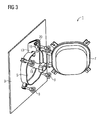
- the hatch is shown with the hatch cover 7 open.
- the guide device 19 is pivoted through the hatch opening 5 and passes through this hatch opening.
- the guide device 19 is in its second end position and is secured in this second end position by means of the securing device 20.
- a part of the guide device 19 is located on one side of the hatch or the hatch opening, for example in the interior of the ship. This part is especially good in FIG. 3 to recognize.
- the other part of the guide device 19 is located on the other side of the hatch or hatch opening, eg outside the ship. This located outside of the ship part of the guide device 19 is particularly good in FIG. 2 to recognize.
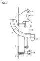
- FIG. 4 is a section through the hatch at the second end position of the guide device shown.
- the hatch 1 represents a unit which has the mounting plate 3, the hatch edge 11, the holding device 13, the guide device 19, the fastening device 23 and the hatch fasteners 9.
- the hatch 1 nor the hatch cover 7, which in FIG. 4 but not shown for reasons of clarity.
- This hatch unit 1 can be prefabricated and z. B. in a shipyard as a complete unit laterally into the outer wall 36 (see. Fig. 5 ) of the ship. As a result, a quick and inexpensive installation is possible.
- FIGS. 1 to 4 the usual installation position of the hatch 1 is shown.
- the channel-shaped curved portion 21 of the guide device 19 is curved in its second end position outside the ship upwards (ie away from the center of the earth).
- This type of curvature advantageously makes it possible to guide the hawser outside the ship.
- the hawser line can be guided by a crane standing on the quay wall to the ship.
- FIG. 5 schematically a moored in a harbor on a quay wall 30 ship 32 is shown, which is connected via an electrical hawser 34 with an on-land medium-voltage network for the purpose of shore power supply.
- the hatch 1 is welded. Of this hatch is essentially only the guide device 19 can be seen.
- the guide device 19 leads the hawser 34 from outside the ship to the interior of the ship or from the interior of the ship to the outside of the ship. Outside the ship, the electrical hawser is led upwards away from the ship and, for example, by means of a holding crane 40, which stands on the quay wall 30, held.
- a hatch has been described, by means of which a single electrical hawser line can be guided through the outer wall of the ship.
- a hatch can also be equipped with a plurality of similar guide devices by means of which several electrical hawser cables can be guided through the outer wall of the ship.
- one or more further similarly constructed guide devices can be arranged laterally next to the guide device 19 shown in the figures, which guide elements are parallel to the illustrated guide device can be swung through the hatch opening.
- the hatch may further be provided with an electrical sensor which, after switching off the shore power supply, removing the electrical hawser line and the pivoting of the guide means 19 in the first end position detects the closing of the hatch cover 7 and generates a corresponding signal.
- penetrating moisture can be detected by means of a sensor arranged in the interior of the ship in the vicinity of the hatch, whereupon a corresponding alarm signal is generated.
Landscapes
- Chemical & Material Sciences (AREA)
- Engineering & Computer Science (AREA)
- Combustion & Propulsion (AREA)
- Mechanical Engineering (AREA)
- Ocean & Marine Engineering (AREA)
- Laying Of Electric Cables Or Lines Outside (AREA)
- Revetment (AREA)
- Other Liquid Machine Or Engine Such As Wave Power Use (AREA)
Description
- Luke für eine Außenwand eines Schiffes, welche eine Führungseinrichtung zur Führung einer elektrischen Trossenleitung durch die Luke aufweist.
- Eine derartige Luke ist aus der
US 5 034 571 A oder derUS 5 235 13 8 A bekannt, welche beide die Merkmale des Oberbegriffs des unabhängigen Anspruchs 1 beschreiben. - Aus der
EP 1 667 301 A1 ist ein Energieversorgungssystem für Schiffe bekannt. - Auf in Häfen liegenden Schiffen wird der an Bord benötigte elektrische Strom üblicherweise durch an Bord befindliche Dieselmotor-Generatoranlagen erzeugt. Beim Betrieb dieser Dieselmotor-Generatoranlagen werden nicht unerhebliche Mengen an Dieselabgasen, welche u.a. Kohlendioxyd und Stickoxyde enthalten, erzeugt, welche umweltschädlich sind.
- Aktuell gibt es Überlegungen, ein im Hafen liegendes Schiff mittels einer flexiblen Energieversorgungsleitung, einer sogenannten Trossenleitung, von Land her mit elektrischem Strom zu versorgen (Landstromversorgung). Dieser elektrische Strom wird mittels eines im Hafen angeordneten elektrischen Energieversorgungsnetzes bereitgestellt und mittels der Trossenleitung zu dem Schiff übertragen. Dabei ist es vorstellbar, die Trossenleitung über eine zufällig gewählte Stelle der Bordaußenwand (Bordwand) des Schiffes zu legen. Allerdings könnte dabei die Trossenleitung beschädigt werden. Außerdem stellen solche planlos über die Bordwand gelegten Trossenleitungen eine Unfallquelle (Stolpergefahr etc.) dar.
- Der Erfindung liegt die Aufgabe zugrunde, eine Vorrichtung anzugeben, mit der eine Trossenleitung sicher und geordnet auf das Schiff gebracht werden kann.
- Erfindungsgemäß gelöst wird diese Aufgabe bei einer Luke der eingangs genannten Art dadurch, dass die Luke eine Lukenöffnung aufweist und die Führungseinrichtung durch die Lukenöffnung hindurch schwenkbar ist.
- Die Führungseinrichtung führt die elektrische Trossenleitung durch die Luke, d.h. von außerhalb des Schiffes in das Innere des Schiffes oder umgekehrt. Die Trossenleitung wird also mittels der Führungseinrichtung durch eine bestimmte Luke des Schiffes geführt. Dadurch ist genau festgelegt, an welcher Stelle des Schiffes die Trossenleitung ins Innere des Schiffes eintritt bzw. austritt. Durch eine entsprechende Kennzeichnung oder andere Schutzmaßnahmen (wie z. B. Schutzzäune oder Schutzgitter) kann diese Stelle entsprechend gesichert werden. Damit ermöglicht diese Luke ein sicheres und geordnetes Eintreten der Trossenleitung in das Schiffsinnere, d. h. in den Innenbereich des Schiffes. Weiterhin werden vorteilhafterweise Beschädigungen der Trossenleitung vermieden, welche z.B. durch scharfe Grate oder Poststellen der Bordwand entstehen können, wenn die Trossenleitung über eine zufällig gewählte Stelle der Bordwand des Schiffes gelegt wird, wobei dadurch, dass die Führungseinrichtung durch die Lukenöffnung hindurch schwenkbar angeordnet ist, vorteilhafterweise bei Nichtgebrauch die Führungseinrichtung aus der Lukenöffnung herausgeschwenkt werden kann, wodurch die Luke für andere Zwecke benutzbar ist.
- Die Luke kann erfindungsgemäß so ausgestaltet sein, dass die Führungseinrichtung eine Krümmung aufweist, durch die eine Durchbiegung einer geführten Trossenleitung begrenzbar ist. Durch eine derart gekrümmte Führungseinrichtung wird erreicht, dass die geführte Trossenleitung eine maximale Krümmung aufweisen kann, welche der Krümmung der Führungseinrichtung entspricht. Dadurch wird die maximale Krümmung der Trossenleitung auf einen Maximalwert begrenzt. Beschädigungen der Trossenleitung durch zu scharfes Abknicken werden dadurch vermieden.
- Die Luke kann auch derart ausgestaltet sein, dass die Führungseinrichtung einen rinnenförmigen Abschnitt zur Aufnahme der Trossenleitung aufweist, wobei der rinnenförmige Abschnitt eine Krümmung aufweist, durch die eine Durchbiegung einer geführten Trossenleitung begrenzbar ist. Mittels dieses rinnenförmigen Abschnittes lässt sich die Trossenleitung besonders sicher und gegen ein Verrutschen geschützt durch die Luke hindurch in das Innere des Schiffes führen. Die Krümmung des rinnenförmigen Abschnittes begrenzt die Durchbiegung der geführten Trossenleitung. Dadurch wird sichergestellt, dass die Trossenleitung im geführten Zustand nicht durch zu scharfes Abknicken beschädigt wird.
- Die Luke kann auch derart ausgestaltet sein, dass an der Führungseinrichtung eine Befestigungseinrichtung zum (zugfesten) Befestigen der Trossenleitung angeordnet ist. Mittels dieser Befestigungseinrichtung kann die Trossenleitung zugfest mit dem Schiff verbunden werden. Dadurch bilden Trossenleitung und Schiff eine mechanische Einheit. Dies ermöglicht auch bei starkem Wind oder Wellengang ein sicheres Vertäuen des Schiffes im Hafen.
- Die Luke kann auch so ausgestaltet sein, dass die Führungseinrichtung zwischen zwei Endstellungen schwenkbar ist, wobei sich die Führungseinrichtung in der ersten Endstellung auf einer Seite der Lukenöffnung befindet und wobei die Führungseinrichtung in der zweiten Endstellung die Lukenöffnung durchgreift. Bei dieser Ausgestaltung gibt es vorteilhafterweise zwei definierte Endstellungen für die Führungseinrichtung: In der ersten Endstellung befindet sich die Führungseinrichtung z.B. bei Nichtgebrauch auf einer Seite der Lukenöffnung (vorzugsweise im Inneren des Schiffes). In dieser ersten Endstellung wird die Lukenöffnung freigegeben, wodurch die Luke für andere Zwecke nutzbar bleibt. Des Weiteren wird die Führungseinrichtung in der ersten Endstellung vor Beschädigungen geschützt, beispielsweise bei Anlegemanövern des Schiffes. In der zweiten Endstellung durchgreift die Führungseinrichtung die Lukenöffnung und ist zum Führen der Trossenleitung bereit. Diese zweite Endstellung wird vorzugsweise erst dann eingenommen, wenn das Schiff sicher im Hafen festgemacht ist.
- Die Luke kann auch so ausgestaltet sein, dass die Luke einen Lukendeckel aufweist, mittels dem die Lukenöffnung verschließbar ist, wenn sich die Führungseinrichtung in der ersten Endstellung befindet. Mittels dieses Lukendeckels kann die Luke vorteilhafterweise verschlossen werden, wenn sich die Führungseinrichtung in der ersten Endstellung befindet. Dadurch wird z. B. auf See das Eindringen von Wasser in das Innere des Schiffes verhindert.
- Die Luke kann auch so ausgestaltet sein, dass die Luke eine Halteeinrichtung aufweist, mit der die Führungseinrichtung schwenkbar verbunden ist. Diese Halteeinrichtung ermöglicht das Schwenken der Führungseinrichtung zwischen der ersten Endstellung und der zweiten Endstellung.
- Die oben genannte Aufgabe wird ebenfalls gelöst durch ein Schiff mit einer Luke nach einem der Ansprüche 1 bis 8.
- Im Folgenden wird die Erfindung anhand eines Ausführungsbeispiels näher erläutert. Dazu ist in
- Figur 1
- eine zum Einbau in eine Bordwand eines Schiffes vorgesehene Luke im geschlossenen Zustand, in
- Figur 2
- die Luke im geöffneten Zustand vom Schiffsäußeren her gesehen, in
- Figur 3
- die Luke im geöffneten Zustand vom Schiffsinneren her gesehen, in
- Figur 4
- eine Schnittansicht der Luke und in
- Figur 5
- eine Schnittansicht eines im Hafen festgemachten Schiffes dargestellt.
- In
Figur 1 ist eine Luke 1 dargestellt, welche zum Einsetzen in eine äußere Bordwand (Außenwand) eines Schiffes vorgesehen ist. Diese Luke weist eine Montageplatte 3 auf, die in eine Öffnung der Außenwand des Schiffes eingesetzt (z.B. eingeschweißt) wird. Die Luke 1 weist weiterhin eine Lukenöffnung 5 auf, welche durch einen Lukendeckel 7 verschließbar ist. Im Ausführungsbeispiel derFigur 1 ist dieser Lukendeckel 7 mittels Lukenverschlüssen 9 wasserdicht verschlossen. In diesem Ausführungsbeispiel sind die Lukenverschlüsse als Knebelschrauben ausgebildet. Die Lukenöffnung 5 ist von einer Lukenumrandung 11 umgeben, welche auch als Lukensüll bezeichnet wird. Mit der Lukenumrandung 11 ist eine Halteeinrichtung 13 verbunden, welche einen Bolzen 15 eines Scharniers aufnimmt. Mittels dieses Scharniers ist eine Führungseinrichtung 19 schwenkbar verbunden, welche zur Führung einer elektrischen Trossenleitung vorgesehen ist. Eine elektrische Trossenleitung ist ein flexibles (insb. hochflexibles) Kabel. Eine solche Trossenleitung kann z.B. einen Durchmesser von ca. 70 mm aufweisen. Bei der mittels der Führungseinrichtung durch die Außenwand des Schiffes geführten elektrischen Trossenleitung kann es sich vorzugsweise um eine Mittelspannungsleitung handeln, welche dem Anschluss des Schiffes an das landseitige Mittelspannungsnetz dient. Beispielsweise können mittels einer solchen Trossenleitung Ströme im Bereich bis 500 A und Spannungen bis 11 kV übertragen werden. - In
Figur 1 ist die Führungseinrichtung 19 in eine erste Endstellung geschwenkt und mittels einer Sicherungsvorrichtung 20 (die als Sicherungsstift 20 ausgebildet ist) in dieser ersten Endstellung gesichert. In dieser ersten Endstellung befindet sich die Führungseinrichtung 19 vollständig auf einer Seite der Luke bzw. der Lukenöffnung 5, nämlich im Innenraum des Schiffes. Die Führungseinrichtung 19 weist einen rinnenförmigen Abschnitt 21 (Halbschale 21) auf, welcher zur Aufnahme der Trossenleitung ausgebildet ist. Die Ausnehmung des rinnenförmigen Abschnittes weist dazu eine Größe bzw. Form auf, die an den Querschnitt der zu führenden Trossenleitung angepasst ist. Weiterhin weist der rinnenförmige Abschnitt 21 der Führungseinrichtung 19 eine Krümmung auf, welche die Durchbiegung der geführten Trossenleitung auf einen Maximalwert begrenzt, d.h. den Biegeradius der Trossenleitung wird auf einen Minimalwert begrenzt. Dadurch werden Beschädigungen durch zu starkes oder scharfes Abknicken der geführten Trossenleitung verhindert. - Weiterhin weist die Führungseinrichtung 19 eine Befestigungseinrichtung 23 auf, an der die geführte Trossenleitung befestigt wird. Diese Befestigungseinrichtung besteht im Ausführungsbeispiel aus zwei mittels Gewindebolzen gegeneinander verspannbaren Halbschalen, welche die geführte Trossenleitung fest zwischen sich einspannen und damit dafür sorgen, dass das Schiff und die Trossenleitung zu einer stabilen Einheit verbunden werden. Diese Befestigungseinrichtung 23 ermöglicht eine Zugentlastung des Trossenkabels. Durch diese Befestigungseinrichtung 23 wird das Schiff mit der Trossenleitung zu einem mechanisch fest verbundenen System. Ein ggf. durch die Gezeiten entstehender Tidenhub, d. h. eine vertikale Bewegung des Schiffes an der Kaimauer, wird auf der Landseite durch ein entsprechendes Nachgeben oder Anziehen der Trossenleitung, beispielsweise mittels eines landseitigen Kabelzuführungssystems ausgeglichen.
- In den
Figuren 2 und3 ist die Luke bei geöffnetem Lukendeckel 7 dargestellt. Die Führungseinrichtung 19 ist durch die Lukenöffnung 5 hindurch verschwenkt und durchgreift diese Lukenöffnung. Die Führungseinrichtung 19 befindet sich in ihrer zweiten Endstellung und ist in dieser zweiten Endstellung mittels der Sicherungsvorrichtung 20 gesichert. Ein Teil der Führungseinrichtung 19 befindet sich auf der einen Seite der Luke bzw. der Lukenöffnung, z.B. im Inneren des Schiffes. Dieser Teil ist besonders gut inFigur 3 zu erkennen. Der andere Teil der Führungseinrichtung 19 befindet sich auf der anderen Seite der Luke bzw. der Lukenöffnung, z.B. außerhalb des Schiffes. Dieser sich außerhalb des Schiffes befindende Teil der Führungseinrichtung 19 ist besonders gut inFigur 2 zu erkennen. - In
Figur 4 ist ein Schnitt durch die Luke bei zweiter Endstellung der Führungseinrichtung dargestellt. Hierbei ist gut zu erkennen, dass die Luke 1 eine Einheit darstellt, welche die Montageplatte 3, die Lukenumrandung 11, die Halteeinrichtung 13, die Führungseinrichtung 19, die Befestigungseinrichtung 23 und die Lukenverschlüsse 9 aufweist. Weiterhin weist die Luke 1 noch den Lukendeckel 7 auf, der inFigur 4 aber aus Gründen der Übersichtlichkeit nicht dargestellt ist. Diese Lukeneinheit 1 kann vorgefertigt werden und wird z. B. in einer Werft als komplette Einheit seitlich in die Außenwand 36 (vgl.Fig. 5 ) des Schiffes eingeschweißt. Dadurch ist eine schnelle und kostengünstige Montage möglich. - Es wird darauf hingewiesen, dass in den
Figuren 1 bis 4 die übliche Einbaulage der Luke 1 dargestellt ist. Das bedeutet, dass der rinnenförmige gekrümmte Abschnitt 21 der Führungseinrichtung 19 in seiner zweiten Endstellung außerhalb des Schiffes nach oben (also vom Erdmittelpunkt weg) gekrümmt ist. Diese Art der Krümmung ermöglicht es vorteilhafterweise, die Trossenleitung außerhalb des Schiffes nach oben zu führen. Beispielsweise kann die Trossenleitung von einem auf der Kaimauer stehenden Kran an das Schiff herangeführt werden. - In
Figur 5 ist schematisch ein in einem Hafen an einer Kaimauer 30 vertäut liegendes Schiff 32 dargestellt, welches über eine elektrische Trossenleitung 34 mit einem an Land befindlichen Mittelspannungsnetz zum Zwecke der Landstromversorgung verbunden ist. In der Außenwand 36 des Schiffes 32 ist die Luke 1 eingeschweißt. Von dieser Luke ist im Wesentlichen lediglich die Führungseinrichtung 19 zu erkennen. Die Führungseinrichtung 19 führt die Trossenleitung 34 von außerhalb des Schiffes ins Innere des Schiffes bzw. vom Inneren des Schiffes nach außerhalb des Schiffes. Außerhalb des Schiffes wird die elektrische Trossenleitung nach oben vom Schiff weggeführt und z.B. mittels eines Haltekranes 40, welcher auf der Kaimauer 30 steht, gehalten. - Im Ausführungsbeispiel wurde eine Luke beschrieben, mittels der eine einzige elektrische Trossenleitung durch die Bordaußenwand des Schiffes geführt werden kann. Eine derartige Luke kann aber auch mit mehreren gleichartigen Führungseinrichtungen ausgerüstet werden, mittels der mehrere elektrische Trossenleitungen durch die Bordaußenwand des Schiffes geführt werden können. Beispielsweise können seitlich neben der in den Figuren dargestellten Führungseinrichtung 19 eine oder mehrere weitere ähnlich aufgebaute Führungseinrichtungen angeordnet sein, welche parallel zu der dargestellten Führungseinrichtung durch die Lukenöffnung geschwenkt werden können. Die Luke kann weiterhin mit einem elektrischen Sensor versehen sein, welcher nach dem Abschalten der Landstromversorgung, dem Entfernen der elektrischen Trossenleitung und dem Verschwenken der Führungseinrichtung 19 in die erste Endstellung das Schließen des Lukendeckels 7 erkennt und ein entsprechendes Signal erzeugt. Weiterhin kann mittels eines im Inneren des Schiffes in der Nähe der Luke angeordneten Sensors eindringende Feuchtigkeit erkannt werden, woraufhin ein entsprechendes Alarmsignal erzeugt wird.
- Es wurde eine Luke für eine Außenwand eines Schiffes und ein Schiff beschrieben, bei denen eine für die Stromversorgung des Schiffes vorgesehene elektrische Trossenleitung sicher und vor Beschädigungen geschützt durch die Außenwand des Schiffes ins Innere des Schiffes geführt werden kann.
Claims (8)
- Luke (1) für eine Außenwand (36) eines Schiffes (32), welche eine Führungseinrichtung (19) zur Führung einer elektrischen Trossenleitung (34) durch die Luke zur Versorgung des Schiffes (32) mit elektrischer Energie aufweist, dadurch gekennzeichnet, dass
die Luke eine Lukenöffnung (5) aufweist und die Führungseinrichtung (19) durch die Lukenöffnung (5) hindurch schwenkbar ist. - Luke nach Anspruch 1,
dadurch gekennzeichnet, dass
die Führungseinrichtung (19) eine Krümmung aufweist, durch die eine Durchbiegung einer geführten Trossenleitung (34) begrenzbar ist. - Luke nach Anspruch 1 oder 2,
dadurch gekennzeichnet, dass
die Führungseinrichtung (19) einen rinnenförmigen Abschnitt (21) zur Aufnahme der Trossenleitung (34) aufweist, wobei der rinnenförmige Abschnitt (21) eine Krümmung aufweist, durch die eine Durchbiegung einer geführten Trossenleitung begrenzbar ist. - Luke nach einem der vorhergehenden Ansprüche,
dadurch gekennzeichnet, dass
an der Führungseinrichtung (19) eine Befestigungseinrichtung (23) zum Befestigen der Trossenleitung angeordnet ist. - Luke nach einem der vorhergehenden Ansprüche,
dadurch gekennzeichnet, dass
die Führungseinrichtung (19) zwischen zwei Endstellungen schwenkbar ist, wobei sich die Führungseinrichtung (19) in der ersten Endstellung auf einer Seite der Lukenöffnung (5) befindet und wobei die Führungseinrichtung in der zweiten Endstellung die Lukenöffnung (5) durchgreift. - Luke nach einem der vorhergehenden Ansprüche,
dadurch gekennzeichnet, dass
die Luke (1) einen Lukendeckel (7) aufweist, mittels dem die Lukenöffnung (5) verschließbar ist, wenn sich die Führungseinrichtung (19) in der ersten Endstellung befindet. - Luke nach einem der vorhergehenden Ansprüche,
dadurch gekennzeichnet, dass
die Luke (1) eine Halteeinrichtung (13) aufweist, mit der die Führungseinrichtung (19) schwenkbar verbunden ist. - Schiff (32) mit einer Luke (1) nach einem der Ansprüche 1 bis 7.
Applications Claiming Priority (2)
| Application Number | Priority Date | Filing Date | Title |
|---|---|---|---|
| DE102010019658A DE102010019658A1 (de) | 2010-04-30 | 2010-04-30 | Schiffsluke |
| PCT/EP2011/056424 WO2011134888A1 (de) | 2010-04-30 | 2011-04-21 | Schiffsluke |
Publications (2)
| Publication Number | Publication Date |
|---|---|
| EP2563646A1 EP2563646A1 (de) | 2013-03-06 |
| EP2563646B1 true EP2563646B1 (de) | 2014-06-25 |
Family
ID=44279264
Family Applications (1)
| Application Number | Title | Priority Date | Filing Date |
|---|---|---|---|
| EP11717549.7A Not-in-force EP2563646B1 (de) | 2010-04-30 | 2011-04-21 | Schiffsluke |
Country Status (6)
| Country | Link |
|---|---|
| US (1) | US8978569B2 (de) |
| EP (1) | EP2563646B1 (de) |
| KR (1) | KR20120132576A (de) |
| CN (1) | CN102869566B (de) |
| DE (1) | DE102010019658A1 (de) |
| WO (1) | WO2011134888A1 (de) |
Cited By (1)
| Publication number | Priority date | Publication date | Assignee | Title |
|---|---|---|---|---|
| CN109398604A (zh) * | 2018-10-18 | 2019-03-01 | 上海外高桥造船有限公司 | 一种用于船舶露天甲板的存储箱 |
Families Citing this family (12)
| Publication number | Priority date | Publication date | Assignee | Title |
|---|---|---|---|---|
| KR101323834B1 (ko) | 2012-07-19 | 2013-10-31 | 삼성중공업 주식회사 | 월 해치 구조 및 이를 포함하는 선박 |
| KR101378965B1 (ko) * | 2012-07-19 | 2014-03-27 | 삼성중공업 주식회사 | 월 해치 구조 및 이를 포함하는 선박 |
| KR101516559B1 (ko) * | 2014-01-14 | 2015-05-04 | 삼성중공업 주식회사 | 선박의 해치 구조 |
| CN104443269A (zh) * | 2014-12-08 | 2015-03-25 | 无锡市东舟船舶附件有限公司 | 开启舷窗 |
| DE102015107776B4 (de) | 2015-05-18 | 2018-07-19 | Thyssenkrupp Ag | Vorrichtung zum Öffnen und/oder Schließen einer Luke |
| CN110053721A (zh) * | 2018-01-19 | 2019-07-26 | 上海船厂船舶有限公司 | 补给软管悬挂装置及含其的装载站 |
| NO344931B1 (en) * | 2019-05-29 | 2020-07-06 | Zinus As | System for handling and coupling electrical cables |
| CN110445084A (zh) * | 2019-09-03 | 2019-11-12 | 中船黄埔文冲船舶有限公司 | 一种自升式平台潜水泵电缆的导缆装置 |
| EP4107334A4 (de) * | 2020-02-20 | 2024-03-13 | Stranger, James | Autonome betätigungssysteme mit intelligenter klappe für lukenfenster und -türen |
| CN113602418A (zh) * | 2021-08-27 | 2021-11-05 | 江南造船(集团)有限责任公司 | 一种水密舱盖及其使用方法 |
| CN114408093A (zh) * | 2022-01-29 | 2022-04-29 | 中船黄埔文冲船舶有限公司 | 一种用于导出电缆的船用舱口盖及船舶 |
| CN115180069B (zh) * | 2022-08-25 | 2023-12-22 | 江苏省镇江船厂(集团)有限公司 | 一种船舶多功能舱口盖盖合装置 |
Family Cites Families (16)
| Publication number | Priority date | Publication date | Assignee | Title |
|---|---|---|---|---|
| US3279413A (en) | 1965-01-07 | 1966-10-18 | Robert E Peterson | Boat anchor hoist |
| DE1506234B1 (de) * | 1967-01-25 | 1970-08-20 | Blohm Voss Ag | Faltbare abdekung fuer decksoeffnungen |
| US3604381A (en) * | 1969-06-11 | 1971-09-14 | Lawrence L Neidenberg | Power cable handling device |
| US4853500A (en) * | 1987-12-11 | 1989-08-01 | Wyle Laboratories | Jamfree cable storage |
| US5034571A (en) * | 1989-11-13 | 1991-07-23 | Galloway Albert D | Power cord retractor for recreational vehicle |
| US5235138A (en) | 1991-06-24 | 1993-08-10 | Shah Jagdish H | Penetration plug for pressure vessels |
| GB9623713D0 (en) * | 1996-11-14 | 1997-01-08 | Hartley Brian | Semi-automatic electric cable extension reel |
| EP1122164A3 (de) * | 2000-02-02 | 2001-09-05 | Hamworthy KSE GmbH | Vorrichtung zur Bildung einer aus dem Bereich eines Rumpfes einer Jacht herausbewegbaren Nutzfläche |
| DE20100148U1 (de) | 2001-01-04 | 2001-06-07 | Kruse, Lothar, Dipl.-Päd., 13351 Berlin | Schiffseigene Kabelführung |
| US7451717B1 (en) * | 2004-05-21 | 2008-11-18 | Conocophillips Company | Systems and processes for covering openings of marine vessel hulls |
| EP1667301A1 (de) | 2004-12-01 | 2006-06-07 | Ipalco B.V. | Seestromversorgungssystem |
| KR100572403B1 (ko) | 2005-10-26 | 2006-04-18 | 이석희 | 풀링 장치 및 그 풀링 방법 |
| FR2899029B1 (fr) * | 2006-03-21 | 2008-06-27 | Snecma Sa | Dispositif et procede de connexion d'une ligne de puissance electrique entre un navire et un terminal |
| KR200430864Y1 (ko) | 2006-07-14 | 2006-11-13 | 주식회사 정아마린 | 선박용 전원공급 케이블 릴 장치 |
| NO20063699L (no) | 2006-08-17 | 2008-02-18 | Rolls Royce Marine As | Anordning ved en haikjeft |
| FR2946471B1 (fr) | 2009-06-05 | 2011-07-15 | New Generation Natural Gas | Dispositif et procede d'alimentation terrestre d'un mobile, notamment d'un navire |
-
2010
- 2010-04-30 DE DE102010019658A patent/DE102010019658A1/de not_active Withdrawn
-
2011
- 2011-04-21 WO PCT/EP2011/056424 patent/WO2011134888A1/de not_active Ceased
- 2011-04-21 KR KR1020127028229A patent/KR20120132576A/ko not_active Ceased
- 2011-04-21 US US13/695,114 patent/US8978569B2/en not_active Expired - Fee Related
- 2011-04-21 CN CN201180021784.0A patent/CN102869566B/zh not_active Expired - Fee Related
- 2011-04-21 EP EP11717549.7A patent/EP2563646B1/de not_active Not-in-force
Cited By (1)
| Publication number | Priority date | Publication date | Assignee | Title |
|---|---|---|---|---|
| CN109398604A (zh) * | 2018-10-18 | 2019-03-01 | 上海外高桥造船有限公司 | 一种用于船舶露天甲板的存储箱 |
Also Published As
| Publication number | Publication date |
|---|---|
| KR20120132576A (ko) | 2012-12-05 |
| US20130220198A1 (en) | 2013-08-29 |
| CN102869566A (zh) | 2013-01-09 |
| US8978569B2 (en) | 2015-03-17 |
| WO2011134888A1 (de) | 2011-11-03 |
| CN102869566B (zh) | 2016-04-20 |
| DE102010019658A1 (de) | 2011-11-03 |
| EP2563646A1 (de) | 2013-03-06 |
Similar Documents
| Publication | Publication Date | Title |
|---|---|---|
| DE102010019658A1 (de) | Schiffsluke | |
| DE2613851C3 (de) | Vorrichtung zum Festmachen eines Schiffes | |
| DE3723393A1 (de) | Anordnung zum verlegen von seismischen kabeln | |
| DE102009015603A1 (de) | Landanschluss für Schiffe mit einem Gelenkkran | |
| EP2681108A1 (de) | Energieversorgungseinrichtung | |
| EP2280897A1 (de) | Vorrichtung zum sicheren übersetzen von personal oder material von einem als schiff ausgebildeten objekt auf ein relativ dazu bewegtes objekt und schiff mit der vorrichtung | |
| US7677532B2 (en) | System to guide a wire, chain or cable onboard a vessel | |
| EP3959123B1 (de) | Einrichtung zur versorgung eines verbrauchers | |
| DE19719306C2 (de) | Schleppkörper | |
| DE1531026B2 (de) | Unterwasser-Einpunkt-Ladeeinrichtung zum Be- und Entladen von Schiffen, die fluidisiertes Gut transportieren | |
| DE102014213342B4 (de) | Kabelführungssystem mit richtungsveränderlicher Kabelführung | |
| WO2020234368A1 (de) | System und verfahren zur versorgung von wasserfahrzeugen, insbesondere schiffen, in einem hafen mit elektrischem strom und be- und entladevorrichtung für ein solches system und verfahren | |
| EP3299273B1 (de) | Vorrichtung und verfahren zum an- und ablegen von wasserfahrzeugen | |
| WO2019215297A1 (de) | Landstromanschluss für containerschiffe | |
| DE4128513A1 (de) | Verfahren und vorrichtung zum fieren oder einholen des versorgungsleitungskabels einer unterwassereinrichtung | |
| DE2923557A1 (de) | Poller zum festmachen von wasserfahrzeugen und verfahren zum festmachen mit hilfe desselben | |
| CN221477438U (zh) | 一种船舶缆绳引缆抛投器 | |
| WO2012116920A2 (de) | Energieversorgungseinrichtung | |
| DE202010011257U1 (de) | Bereitschaftsboot-/Rettungsinseldavit | |
| EP3174784A1 (de) | Rettungssystem zur rettung von besatzungsmitgliedern eines schiffs | |
| DE68903978T2 (de) | Kettenfoermige unterwasserkabel. | |
| AT518495B1 (de) | Aussenbordantrieb mit elektromotor | |
| DE202019105657U1 (de) | Anordnung von Solarpaneelen an einem Mast | |
| WO2012116914A2 (de) | Energieversorgungseinrichtung | |
| DE102024126531A1 (de) | Landstromanschlussvorrichtung zum Anschließen eines Schiffes an ein Landstromversorgungsnetz |
Legal Events
| Date | Code | Title | Description |
|---|---|---|---|
| PUAI | Public reference made under article 153(3) epc to a published international application that has entered the european phase |
Free format text: ORIGINAL CODE: 0009012 |
|
| 17P | Request for examination filed |
Effective date: 20121019 |
|
| AK | Designated contracting states |
Kind code of ref document: A1 Designated state(s): AL AT BE BG CH CY CZ DE DK EE ES FI FR GB GR HR HU IE IS IT LI LT LU LV MC MK MT NL NO PL PT RO RS SE SI SK SM TR |
|
| RAP1 | Party data changed (applicant data changed or rights of an application transferred) |
Owner name: SIEMENS AKTIENGESELLSCHAFT |
|
| DAX | Request for extension of the european patent (deleted) | ||
| GRAP | Despatch of communication of intention to grant a patent |
Free format text: ORIGINAL CODE: EPIDOSNIGR1 |
|
| INTG | Intention to grant announced |
Effective date: 20140123 |
|
| GRAS | Grant fee paid |
Free format text: ORIGINAL CODE: EPIDOSNIGR3 |
|
| GRAA | (expected) grant |
Free format text: ORIGINAL CODE: 0009210 |
|
| AK | Designated contracting states |
Kind code of ref document: B1 Designated state(s): AL AT BE BG CH CY CZ DE DK EE ES FI FR GB GR HR HU IE IS IT LI LT LU LV MC MK MT NL NO PL PT RO RS SE SI SK SM TR |
|
| REG | Reference to a national code |
Ref country code: GB Ref legal event code: FG4D Free format text: NOT ENGLISH |
|
| REG | Reference to a national code |
Ref country code: CH Ref legal event code: EP |
|
| REG | Reference to a national code |
Ref country code: AT Ref legal event code: REF Ref document number: 674468 Country of ref document: AT Kind code of ref document: T Effective date: 20140715 |
|
| REG | Reference to a national code |
Ref country code: IE Ref legal event code: FG4D Free format text: LANGUAGE OF EP DOCUMENT: GERMAN |
|
| REG | Reference to a national code |
Ref country code: DE Ref legal event code: R096 Ref document number: 502011003558 Country of ref document: DE Effective date: 20140807 |
|
| REG | Reference to a national code |
Ref country code: NL Ref legal event code: T3 |
|
| PG25 | Lapsed in a contracting state [announced via postgrant information from national office to epo] |
Ref country code: CY Free format text: LAPSE BECAUSE OF FAILURE TO SUBMIT A TRANSLATION OF THE DESCRIPTION OR TO PAY THE FEE WITHIN THE PRESCRIBED TIME-LIMIT Effective date: 20140625 Ref country code: FI Free format text: LAPSE BECAUSE OF FAILURE TO SUBMIT A TRANSLATION OF THE DESCRIPTION OR TO PAY THE FEE WITHIN THE PRESCRIBED TIME-LIMIT Effective date: 20140625 Ref country code: NO Free format text: LAPSE BECAUSE OF FAILURE TO SUBMIT A TRANSLATION OF THE DESCRIPTION OR TO PAY THE FEE WITHIN THE PRESCRIBED TIME-LIMIT Effective date: 20140925 Ref country code: LT Free format text: LAPSE BECAUSE OF FAILURE TO SUBMIT A TRANSLATION OF THE DESCRIPTION OR TO PAY THE FEE WITHIN THE PRESCRIBED TIME-LIMIT Effective date: 20140625 Ref country code: GR Free format text: LAPSE BECAUSE OF FAILURE TO SUBMIT A TRANSLATION OF THE DESCRIPTION OR TO PAY THE FEE WITHIN THE PRESCRIBED TIME-LIMIT Effective date: 20140926 |
|
| REG | Reference to a national code |
Ref country code: LT Ref legal event code: MG4D |
|
| PG25 | Lapsed in a contracting state [announced via postgrant information from national office to epo] |
Ref country code: RS Free format text: LAPSE BECAUSE OF FAILURE TO SUBMIT A TRANSLATION OF THE DESCRIPTION OR TO PAY THE FEE WITHIN THE PRESCRIBED TIME-LIMIT Effective date: 20140625 Ref country code: SE Free format text: LAPSE BECAUSE OF FAILURE TO SUBMIT A TRANSLATION OF THE DESCRIPTION OR TO PAY THE FEE WITHIN THE PRESCRIBED TIME-LIMIT Effective date: 20140625 Ref country code: LV Free format text: LAPSE BECAUSE OF FAILURE TO SUBMIT A TRANSLATION OF THE DESCRIPTION OR TO PAY THE FEE WITHIN THE PRESCRIBED TIME-LIMIT Effective date: 20140625 Ref country code: HR Free format text: LAPSE BECAUSE OF FAILURE TO SUBMIT A TRANSLATION OF THE DESCRIPTION OR TO PAY THE FEE WITHIN THE PRESCRIBED TIME-LIMIT Effective date: 20140625 |
|
| PG25 | Lapsed in a contracting state [announced via postgrant information from national office to epo] |
Ref country code: SK Free format text: LAPSE BECAUSE OF FAILURE TO SUBMIT A TRANSLATION OF THE DESCRIPTION OR TO PAY THE FEE WITHIN THE PRESCRIBED TIME-LIMIT Effective date: 20140625 Ref country code: PT Free format text: LAPSE BECAUSE OF FAILURE TO SUBMIT A TRANSLATION OF THE DESCRIPTION OR TO PAY THE FEE WITHIN THE PRESCRIBED TIME-LIMIT Effective date: 20141027 Ref country code: EE Free format text: LAPSE BECAUSE OF FAILURE TO SUBMIT A TRANSLATION OF THE DESCRIPTION OR TO PAY THE FEE WITHIN THE PRESCRIBED TIME-LIMIT Effective date: 20140625 Ref country code: RO Free format text: LAPSE BECAUSE OF FAILURE TO SUBMIT A TRANSLATION OF THE DESCRIPTION OR TO PAY THE FEE WITHIN THE PRESCRIBED TIME-LIMIT Effective date: 20140625 Ref country code: CZ Free format text: LAPSE BECAUSE OF FAILURE TO SUBMIT A TRANSLATION OF THE DESCRIPTION OR TO PAY THE FEE WITHIN THE PRESCRIBED TIME-LIMIT Effective date: 20140625 Ref country code: ES Free format text: LAPSE BECAUSE OF FAILURE TO SUBMIT A TRANSLATION OF THE DESCRIPTION OR TO PAY THE FEE WITHIN THE PRESCRIBED TIME-LIMIT Effective date: 20140625 |
|
| PG25 | Lapsed in a contracting state [announced via postgrant information from national office to epo] |
Ref country code: IS Free format text: LAPSE BECAUSE OF FAILURE TO SUBMIT A TRANSLATION OF THE DESCRIPTION OR TO PAY THE FEE WITHIN THE PRESCRIBED TIME-LIMIT Effective date: 20141025 Ref country code: PL Free format text: LAPSE BECAUSE OF FAILURE TO SUBMIT A TRANSLATION OF THE DESCRIPTION OR TO PAY THE FEE WITHIN THE PRESCRIBED TIME-LIMIT Effective date: 20140625 |
|
| REG | Reference to a national code |
Ref country code: DE Ref legal event code: R097 Ref document number: 502011003558 Country of ref document: DE |
|
| PG25 | Lapsed in a contracting state [announced via postgrant information from national office to epo] |
Ref country code: IT Free format text: LAPSE BECAUSE OF FAILURE TO SUBMIT A TRANSLATION OF THE DESCRIPTION OR TO PAY THE FEE WITHIN THE PRESCRIBED TIME-LIMIT Effective date: 20140625 Ref country code: DK Free format text: LAPSE BECAUSE OF FAILURE TO SUBMIT A TRANSLATION OF THE DESCRIPTION OR TO PAY THE FEE WITHIN THE PRESCRIBED TIME-LIMIT Effective date: 20140625 |
|
| PLBE | No opposition filed within time limit |
Free format text: ORIGINAL CODE: 0009261 |
|
| STAA | Information on the status of an ep patent application or granted ep patent |
Free format text: STATUS: NO OPPOSITION FILED WITHIN TIME LIMIT |
|
| 26N | No opposition filed |
Effective date: 20150326 |
|
| PG25 | Lapsed in a contracting state [announced via postgrant information from national office to epo] |
Ref country code: SI Free format text: LAPSE BECAUSE OF FAILURE TO SUBMIT A TRANSLATION OF THE DESCRIPTION OR TO PAY THE FEE WITHIN THE PRESCRIBED TIME-LIMIT Effective date: 20140625 Ref country code: MC Free format text: LAPSE BECAUSE OF FAILURE TO SUBMIT A TRANSLATION OF THE DESCRIPTION OR TO PAY THE FEE WITHIN THE PRESCRIBED TIME-LIMIT Effective date: 20140625 Ref country code: LU Free format text: LAPSE BECAUSE OF FAILURE TO SUBMIT A TRANSLATION OF THE DESCRIPTION OR TO PAY THE FEE WITHIN THE PRESCRIBED TIME-LIMIT Effective date: 20150421 |
|
| REG | Reference to a national code |
Ref country code: CH Ref legal event code: PL |
|
| GBPC | Gb: european patent ceased through non-payment of renewal fee |
Effective date: 20150421 |
|
| REG | Reference to a national code |
Ref country code: IE Ref legal event code: MM4A |
|
| PG25 | Lapsed in a contracting state [announced via postgrant information from national office to epo] |
Ref country code: GB Free format text: LAPSE BECAUSE OF NON-PAYMENT OF DUE FEES Effective date: 20150421 Ref country code: LI Free format text: LAPSE BECAUSE OF NON-PAYMENT OF DUE FEES Effective date: 20150430 Ref country code: CH Free format text: LAPSE BECAUSE OF NON-PAYMENT OF DUE FEES Effective date: 20150430 |
|
| PG25 | Lapsed in a contracting state [announced via postgrant information from national office to epo] |
Ref country code: IE Free format text: LAPSE BECAUSE OF NON-PAYMENT OF DUE FEES Effective date: 20150421 |
|
| REG | Reference to a national code |
Ref country code: FR Ref legal event code: PLFP Year of fee payment: 6 |
|
| PGFP | Annual fee paid to national office [announced via postgrant information from national office to epo] |
Ref country code: NL Payment date: 20160420 Year of fee payment: 6 |
|
| PGFP | Annual fee paid to national office [announced via postgrant information from national office to epo] |
Ref country code: DE Payment date: 20160620 Year of fee payment: 6 |
|
| PGFP | Annual fee paid to national office [announced via postgrant information from national office to epo] |
Ref country code: FR Payment date: 20160429 Year of fee payment: 6 Ref country code: BE Payment date: 20160420 Year of fee payment: 6 |
|
| PG25 | Lapsed in a contracting state [announced via postgrant information from national office to epo] |
Ref country code: MT Free format text: LAPSE BECAUSE OF FAILURE TO SUBMIT A TRANSLATION OF THE DESCRIPTION OR TO PAY THE FEE WITHIN THE PRESCRIBED TIME-LIMIT Effective date: 20140625 |
|
| PG25 | Lapsed in a contracting state [announced via postgrant information from national office to epo] |
Ref country code: HU Free format text: LAPSE BECAUSE OF FAILURE TO SUBMIT A TRANSLATION OF THE DESCRIPTION OR TO PAY THE FEE WITHIN THE PRESCRIBED TIME-LIMIT; INVALID AB INITIO Effective date: 20110421 Ref country code: SM Free format text: LAPSE BECAUSE OF FAILURE TO SUBMIT A TRANSLATION OF THE DESCRIPTION OR TO PAY THE FEE WITHIN THE PRESCRIBED TIME-LIMIT Effective date: 20140625 Ref country code: BG Free format text: LAPSE BECAUSE OF FAILURE TO SUBMIT A TRANSLATION OF THE DESCRIPTION OR TO PAY THE FEE WITHIN THE PRESCRIBED TIME-LIMIT Effective date: 20140625 |
|
| REG | Reference to a national code |
Ref country code: AT Ref legal event code: MM01 Ref document number: 674468 Country of ref document: AT Kind code of ref document: T Effective date: 20160421 |
|
| PG25 | Lapsed in a contracting state [announced via postgrant information from national office to epo] |
Ref country code: AT Free format text: LAPSE BECAUSE OF NON-PAYMENT OF DUE FEES Effective date: 20160421 Ref country code: TR Free format text: LAPSE BECAUSE OF FAILURE TO SUBMIT A TRANSLATION OF THE DESCRIPTION OR TO PAY THE FEE WITHIN THE PRESCRIBED TIME-LIMIT Effective date: 20140625 |
|
| REG | Reference to a national code |
Ref country code: DE Ref legal event code: R119 Ref document number: 502011003558 Country of ref document: DE |
|
| REG | Reference to a national code |
Ref country code: NL Ref legal event code: MM Effective date: 20170501 |
|
| REG | Reference to a national code |
Ref country code: FR Ref legal event code: ST Effective date: 20171229 |
|
| PG25 | Lapsed in a contracting state [announced via postgrant information from national office to epo] |
Ref country code: NL Free format text: LAPSE BECAUSE OF NON-PAYMENT OF DUE FEES Effective date: 20170501 Ref country code: DE Free format text: LAPSE BECAUSE OF NON-PAYMENT OF DUE FEES Effective date: 20171103 Ref country code: FR Free format text: LAPSE BECAUSE OF NON-PAYMENT OF DUE FEES Effective date: 20170502 |
|
| REG | Reference to a national code |
Ref country code: BE Ref legal event code: MM Effective date: 20170430 |
|
| PG25 | Lapsed in a contracting state [announced via postgrant information from national office to epo] |
Ref country code: BE Free format text: LAPSE BECAUSE OF NON-PAYMENT OF DUE FEES Effective date: 20170430 |
|
| PG25 | Lapsed in a contracting state [announced via postgrant information from national office to epo] |
Ref country code: MK Free format text: LAPSE BECAUSE OF FAILURE TO SUBMIT A TRANSLATION OF THE DESCRIPTION OR TO PAY THE FEE WITHIN THE PRESCRIBED TIME-LIMIT Effective date: 20140625 |
|
| PG25 | Lapsed in a contracting state [announced via postgrant information from national office to epo] |
Ref country code: AL Free format text: LAPSE BECAUSE OF FAILURE TO SUBMIT A TRANSLATION OF THE DESCRIPTION OR TO PAY THE FEE WITHIN THE PRESCRIBED TIME-LIMIT Effective date: 20140625 |