EP2555082A2 - Anzeigevorrichtungsschrank - Google Patents
Anzeigevorrichtungsschrank Download PDFInfo
- Publication number
- EP2555082A2 EP2555082A2 EP12178678A EP12178678A EP2555082A2 EP 2555082 A2 EP2555082 A2 EP 2555082A2 EP 12178678 A EP12178678 A EP 12178678A EP 12178678 A EP12178678 A EP 12178678A EP 2555082 A2 EP2555082 A2 EP 2555082A2
- Authority
- EP
- European Patent Office
- Prior art keywords
- rear panel
- front panel
- protrusions
- panel
- display module
- Prior art date
- Legal status (The legal status is an assumption and is not a legal conclusion. Google has not performed a legal analysis and makes no representation as to the accuracy of the status listed.)
- Withdrawn
Links
Images



Classifications
-
- G—PHYSICS
- G06—COMPUTING OR CALCULATING; COUNTING
- G06F—ELECTRIC DIGITAL DATA PROCESSING
- G06F1/00—Details not covered by groups G06F3/00 - G06F13/00 and G06F21/00
- G06F1/16—Constructional details or arrangements
- G06F1/1601—Constructional details related to the housing of computer displays, e.g. of CRT monitors, of flat displays
Definitions
- the present invention relates to a display device cabinet for use with thin liquid crystal televisions, for example, and particularly to a display device cabinet that is formed by joining and joining a frame-shaped front panel, which is deployed around a display surface of a display module, with a rear panel.
- a cabinet formed by joining a frame-shaped front panel with a rear panel is widely adopted in display devices such as thin televisions and photo frames, and in general, the front panel and the rear panel are individually molded from a resin with each of the front and rear panels defining an integral unit. Furthermore, in this type of cabinet, a screw fastening mechanism using attachment screws is often adopted for a fixing mechanism for joining, in an integrated manner, the front panel with the rear panel joined to the front panel.
- a conventional example which adopts for the fixing mechanism a combination of a first fixing mechanism that uses attachment screws and a second fixing mechanism that uses no attachment screws. This conventional example will be described with reference to FIG. 6 .
- FIG. 6 is sectional view of principal portions of the conventional example.
- This figure shows a state in which the cabinet of a vertically-placed-type thin liquid crystal television as a display device is placed in a laid-down orientation; 1 indicates a frame-shaped front panel, and 5 indicates a rear panel superimposed on the front panel 1.
- the front panel 1 houses a liquid crystal display module (display module) 8, and the frame-shaped front panel 1 is deployed around the display surface (not illustrated) of this display module 8.
- the rear panel 5 joined to the front panel 1 is joined with the front panel 1 by the first fixing mechanism (not illustrated) that uses attachment screws at specified locations in the lower portion when the cabinet is placed vertically (locations in the vicinity of the lower ends).
- This first fixing mechanism is configured by screwing the attachment screws into bosses provided on the front panel 1, for example, via screw insertion holes formed in the rear panel 5.
- the rear panel 5 is joined with the front panel 1 by the second fixing mechanism 2 that uses no attachment screw at specified locations in the upper portion when the cabinet is vertically placed (locations in the vicinity of the upper ends).
- the second fixing mechanism 2 includes protrusions 4 arranged so as to protrude inward on the edge frame 3 of the front panel 1 that faces the outer frame 9 of the display module 8, a mating piece 6 that is provided on the rear panel 5 and that is fitted inside the edge frame 3 of the front panel 1 in an overlapping manner, and engaging openings 7 that are provided in the mating piece 6 and that respectively mate with the protrusions 4.
- the front panel 1 and the rear panel 5 are joined and joined by a fixing assembly including a combination of the first fixing mechanism and the second fixing mechanism 2.
- the following work is performed in the cabinet assembly process: the rear panel 5 is carried in as indicated by the dotted lines in FIG. 6 directly above the front panel 1 to which the display module 8 is attached and which is in a laid-down orientation, for example, after which the rear panel 5 is brought down as in arrow D in the same figure, and the mating piece 6 thereof is therefore pushed in the inside of the edge frame 3 of the front panel 1.
- the mating piece 6 rides over the protrusions 4 while being flexed and deformed, so the engaging openings 7 respectively mate with the protrusions 4 as this mating piece 6 undergoes deformation recovery. While the engaging openings 7 and the protrusions 4 mate with each other in this manner, the protrusions 4 are engaged with the engaging openings 7 at these mating locations, so it is not very likely to have a situation in which the front panel 1 comes off of the rear panel 5 at these mating locations. Note that the work of joining the front panel 1 and the rear panel 5 by the first fixing mechanism is performed after performing the joining work using the second fixing mechanism 2.
- a disassembly process which involves the work of releasing the joined state by the second fixing mechanism 2 after releasing the joined state by the first fixing mechanism at the joining locations.
- the work of releasing the joined state by the second fixing mechanism 2 there is no choice but to strip off the engaging openings 7 in the mating piece 6 from the protrusions 4 on the side of the front panel 1 and to cause these engaging openings 7 to be forcibly disengaged from the protrusions 4 through the operation of pulling up the rear panel 5 as shown by arrow U in FIG. 6 .
- the protruding width of the protrusions 4 from the edge frame 3 is set such that the mating piece 6 can ride over the protrusions 4 with the push-in operation of the mating piece 6 during the assembly process and also such that the engaging openings 7 in the mating piece 6 can be disengaged from the protrusions 4 through the operation of stripping the engaging openings 7 off of the protrusions 4 during the disassembly process.
- a cabinet is joined using male screws with a frame-form holding body that sandwiches the peripheral portion of a liquid crystal panel between the holding body and a frame in a thin liquid crystal display device (see, for example, Japanese Patent Application Laid-Open Publication No. 2009-151112 , especially FIG. 2 ).
- yet another prior art example shows the structure of a cabinet for a thin display device formed by inserting protruding portions on the upper end portion of the front cabinet between recessed portions in the upper end portion of a front cover and projecting pieces on the upper end portion of the rear cabinet and causing the protruding and recessed portions to interlock (for example, see Japanese Patent Application Laid-Open Publication No. 2008-298964 , especially, FIG. 6 ).
- the protruding width of the protrusions 4 from the edge frame 3 is set such that the mating piece 6 can ride over the protrusions 4 by the push-in operation of the mating piece 6 during the assembly process and also such that the engaging openings 7 in the mating piece 6 can be disengaged from the protrusions 4 through the operation of stripping the engaging openings 7 off of the protrusions 4 during the disassembly process.
- the engaging width (latching margin) between the protrusions 4 and the corresponding engaging openings 7 at the mating locations must be set with a relatively high degree of precision, and if the engaging width is too large, the engaging openings 7 cannot be stripped off of the protrusions 4, which tends to create a hindrance during reworking. On the other hand, if the engaging width is too small, when the cabinet falls off or the like, the engaging openings 7 easily come off of the protrusions 4 due to this impact. Accordingly, with the conventional example described above, there is a problem in that the adjustment of the engaging width is difficult.
- Japanese Patent Application Laid-Open Publication No. 2009-151112 FIG. 2
- Japanese Patent Application Laid-Open Publication No. 2010-191407 paragraph [0007] and FIG. 4
- Japanese Patent Application Laid-Open Publication No. 2008-298964 FIG. 6
- FIG. 6 indicates nothing more than the insertion of the front cabinet between the rear cabinet and the front cover.
- a preferred embodiment of the present invention provides a display device cabinet in which a fixing assembly that joins a front panel that houses a display module and a rear panel includes a combination of a first fixing mechanism that includes attachment screws and a second fixing mechanism that includes no attachment screws, and provides a display device cabinet having a structure such that, even though a mating structure between protrusions on a side of an edge frame of the front panel and engaging openings provided in a mating piece on a side of the rear panel defines the second fixing mechanism, the protrusions and the engaging openings are not easily disengaged from each other.
- a display device cabinet in which the assembly process and disassembly process of the cabinet can be performed without applying excessive force to the protrusions and the engaging openings.
- the display device cabinet is a display device cabinet including a frame-shaped front panel that houses a display module and that is deployed around a display surface of the display module, a rear panel that is joined to the front panel, and a fixing assembly that joins the front panel and the rear panel, with the fixing assembly including a combination of a first fixing mechanism that includes attachment screws and a second fixing mechanism that includes no attachment screw.
- the second fixing mechanism preferably includes protrusions arranged to protrude inward on an edge frame of the front panel that faces the outer frame of the display module spaced at a distance from each other; a mating piece that is provided on the rear panel and that is fitted inside the edge frame of the front panel in an overlapping manner; engaging openings that are provided in the mating piece and that respectively mate with the protrusions; and stopper elements that are provided on the rear panel and that are located in a space between the outer frame of the display module and the edge frame of the front panel, and the stopper elements include contact portions that prevent the protrusions from slipping out of the engaging openings by contacting the outer frame of the display module.
- the front panel and the rear panel are joined by screw fastening via the first fixing mechanism and joined by the mating structure between the protrusions and the corresponding engaging openings of the second fixing mechanism.
- the stopper elements include contact portions that prevent the protrusions from slipping out of the engaging openings by contacting the outer frame of the display module at the joined locations via the second fixing mechanism, such that the stopper elements prevent the protrusions from slipping out of the engaging openings and becoming disengaged. Therefore, even if a drop impact is applied to the cabinet following assembly, a situation in which the protrusions slip out of the engaging openings and end up being disengaged due to this impact is not very likely to arise.
- the stopper elements preferably have a shape that makes it possible to have the engaging openings in the mating piece engaged with the protrusions by inserting the mating piece in the inside of the edge frame of the front panel while maintaining the rear panel in an inclined orientation, and to cause the engaging openings to mate with the protrusions by changing the orientation of the rear panel from the inclined orientation to a horizontal orientation in which the rear panel is joined to the front panel while avoiding interference between the stopper elements and the outer frame of the display module.
- the shape of the stopper elements is configured as described above, there is no need to apply excessive force to the protrusions and the engaging openings during the assembly process and disassembly process of the cabinet. Therefore, it is possible to avoid a situation in which excessive force is applied to the protrusions and the engaging openings during the assembly process and disassembly process, causing these elements ta break.
- the stopper elements preferably are defined by rib-shaped plates that are preferably made of a molded resin and are integral with the rear panel that includes the mating piece, each of the plates is provided on the rear panel and the mating piece in a continuous manner, and one end edge of each of the plates in the width direction defines a contact portion.
- a distance between the contact portions of the stopper elements and the outer frame of the display module is preferably smaller than the engaging width at the mating locations between the protrusions and the respective engaging openings, and as a result of a removed portion preferably being provided on each of the plates by removing the corner portion defined by one end edge of the plate in the width direction defining the contact portion of the stopper element and the end edge in the height direction thereof, it is possible to change the orientation of the rear panel from the inclined orientation to the horizontal orientation in which the rear panel is joined to the front panel while avoiding the interference between the stopper elements and the outer frame of the display module.
- This unique configuration has an advantage in that the shape of the rib-shaped plates defining the stopper elements is simplified, so it becomes corresponding easier to form the molding surface of the mold for molding the stopper elements.
- the front panel and the rear panel are joined to define the cabinet for a vertically placed-type thin liquid crystal television
- the first fixing mechanism joins the front panel and the rear panel at lower portions thereof
- the second fixing mechanism joins the front panel and rear panel and upper portions thereof.
- various preferred embodiments of the present invention provide a cabinet that is immune to damage to the protrusions and the engaging openings during the disassembly process at the time of reworking of the cabinet, in particular, inexpensively without adding components or parts. Moreover, by providing rib-shaped plates to define the stopper elements, the plates reinforce the rear panel and the mating piece.
- FIG. 1 is a schematic perspective view of the display device cabinet according to a preferred embodiment of the present invention as seen from the back.
- FIG. 2 is a side view showing the cabinet of Fig. 1 with a portion thereof cut off.
- FIG. 3 is a longitudinal sectional view showing the portion III of FIG. 2 .
- FIG. 4 is a longitudinal sectional view of principal portions showing as an example the initial stage of the cabinet assembly process.
- FIG. 5 is a longitudinal sectional view of principal portions showing as an example a state in which the cabinet assembly process transitions from an intermediate stage to the final stage.
- FIG. 6 is sectional view of principal portions of a conventional example.
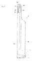
- FIG. 1 is a schematic perspective view of the display device cabinet A according to a preferred embodiment of the present invention as seen from the back, and FIG. 2 is a side view showing the same cabinet A with a portion thereof cut off.
- the cabinet A constitutes the cabinet preferably for use with a vertically placed-type thin liquid crystal television and includes a frame-shaped front panel 10 and a rear panel 50 joined to the front panel 10. Furthermore, the two panels 10 and 50 are joined by a fixing assembly including a combination of a first fixing mechanism that uses attachment screws and a second fixing mechanism that uses no attachment screws, which will be described later.
- a liquid crystal display module as a display module 30 is attached to and housed in the front panel 10, and the display module 30 is covered by the rear panel 50 from the back surface side. Then, the frame-shaped front panel 10 is deployed around the display surface 31 of the liquid crystal module 30.
- a first fixing mechanism 70 that uses attachment screws is configured by screwing attachment screws 72 that are inserted through screw insertion holes provided in the rear panel 50 at locations in the vicinity of the lower end thereof into bosses 71 provided on the front panel 10 at locations in the vicinity of the lower end thereof and by tightening the attachment screws 72 as shown in FIG. 2 .
- this first fixing mechanism 70 joins the front panel 10 and the rear panel 50 at a plurality of locations in the vicinity of the lower end in the height direction of the location where the front panel 10 and the rear panel 50 are joined, for example.
- a second fixing mechanism 80 that uses no attachment screw is used to join the front panel 10 and the rear panel 50 at locations in the vicinity of the upper end of the cabinet A as shown in FIG. 2 .
- this second fixing mechanism 80 will be described.
- FIG. 3 is a longitudinal sectional view showing the portion III of FIG. 2 .
- Fig. 3 shows a state in which the cabinet A is placed in a laid-down orientation with the front panel 10 being on the lower side.
- the front panel 10 preferably is a resin molded body integrally provided with an edge frame 11, and the edge frame 11 faces, spaced at a certain distance, an outer frame 32 of the display module 30 that preferably has a rectangular or substantially rectangular shape when seen in a front view and that is housed in the front panel 10.
- the outer surface of the outer frame 32 facing the edge frame 11 is a flat surface.
- protrusions 81 facing inward are provided on the edge frame 11.
- the protrusions 81 are preferably molded from a resin integrally with the front panel 10, for example.
- the rear panel 50 joined to the front panel 10 is provided with a mating piece 82 that is fitted inside of the edge frame 11 of the front panel 10 in an overlapping manner, and engaging openings 83 provided in the mating piece 82 respectively mate with the protrusions 81.
- the sizes of the engaging openings 83 and protrusions 81 are set such that vibration or wobble that is greater than permissible does not occur at the locations where the engaging openings 83 and the protrusions 81 mate.
- stopper elements 84 preferably defined by rib-shaped plates are preferably integrally molded from a resin on the rear panel 50, for example.
- Each of the rib-shaped plates defining the stopper elements 84 is provided not only on the rear panel 50 but also on the mating piece 82 in a continuous manner. Therefore, the stopper elements 84 are useful as the reinforcing ribs that reinforce the mating piece 82 and the rear panel 50.
- the stopper elements 84 defined by the rib-shaped plates are deployed in the space S between the edge frame 11 of the front panel 10 and the outer frame 32 of the display module 30. Then, one end edge in the width direction W of each of the rib-shaped plates defining the stopper elements 84 is provided as a contact portion 85, and the contact portion 85 faces the outer frame 32 of the display module 30 in a position of close proximity.
- the engaging width (latching margin) at the mating locations between the protrusions 81 on the side of the front panel 10 and the corresponding engaging openings 83 in the mating piece 82 on the side of the rear panel 50 is compared with the distance between the contact portions 85 of the stopper elements 84 and the outer frame 32 of the display module 30, the distance between the contact portions 85 and the outer frame 32 is smaller than the engaging width. Therefore, in a state in which the front panel 10 and the rear panel 50 are not joined by the first fixing mechanism 70 (see FIG. 1 ), even if the front panel 10 and the rear panel 50 are positionally shifted from each other in the height direction H thereof (corresponding to the horizontal direction in FIG.
- this positionally-shifted width will never exceed the distance between the contact portions 85 and the outer frame 32.
- the positionally-shifted width is suppressed to a width smaller than the engaging width at the mating locations. Accordingly, even if such a positional shifting occurs between the front panel 10 and the rear panel 50, there is no possible way to create a situation in which the joined state obtained by the second fixing mechanism 80 ends up being released by the engaging openings 83 slipping off of the corresponding protrusions 81.
- the positional shifting does not occur in a state in which the cabinet A is assembled by joining the front panel 10 and the rear penal 50 via the first fixing mechanism 70. Furthermore, the effect described above is exhibited such that the positionally-shifted width between the front panel 10 and the rear panel 50 is suppressed to a width smaller than the engaging width at the mating locations by the contact portions 85 contacting the outer frame 32, so even if a drop impact is applied to the cabinet A following assembly, it is not very likely to result in a situation in which the protrusions 81 come out of the corresponding engaging openings 83 and end up being disengaged.
- each of the rib-shaped plates defining the stopper elements 84 in concrete terms, the corner portion defined by one end edge in the width direction W of each of the plates defining the contact portion 85 and the end edge 86 in the height direction D of the plate, is removed to define a rounded chamfered shape. This removed portion is indicated with symbol 87 in FIG. 3 .
- FIG. 4 is a longitudinal sectional view of principal portions showing as an example the initial stage of the assembly process
- FIG. 5 is a longitudinal sectional view of principal portions showing as an example a state in which the assembly process transitions from an intermediate stage to the final stage.
- an operation is performed in which the mating piece 82 on the side of the rear panel 50 is inserted as shown in arrow D in the inside of the edge frame 11 of the front panel 10 that is deployed in a horizontal orientation while maintaining the rear panel 50 in an inclined orientation such that the upper end portion thereof faces downward as shown in FIG. 4 .
- an operation for an intermediate stage is performed in which each of the engaging openings 83 in the mating piece 82 is caused to engage with the corresponding protrusion 81 as shown in FIG. 5 .
- the corner portions of the rib-shaped plates defining the stopper elements 84 are respectively provided with the removed portions 87 as described above in this preferred embodiment.
- the plates (stopper elements 84) can be inserted effortlessly into the space S without the corner portions of the plates interfering with the outer frame 32 of the display module 30.
- the shape of the rib-shaped plates defining the stopper elements 84 preferably is a shape that enables the operation of the initial stage which is such that the engaging openings 83 in the mating piece 82 are respectively engaged with the protrusions 81 by inserting the mating piece 82 into the interior of the edge frame 11 of the front panel 10 while maintaining the rear panel 50 in the inclined orientation and the operation of the final stage which is such that the engaging openings 83 are caused to mate respectively with the protrusions 81 by changing the orientation of the rear panel 50 from the inclined orientation to the horizontal orientation in which the rear panel 50 is joined to the front panel 10 while avoiding the interference between the stopper elements 84 and the outer frame 32 of the display module 30.
- the engaging openings 83 provided in the mating piece 82 on the side of the rear panel 50 are caused to mate respectively with the protrusions 81 provided on the edge frame 11 of the front panel 10 from a diagonal direction. Moreover, in the disassembly process, the protrusions 81 are taken out of the engaging openings 83 of the mating piece 82 through the diagonal inclination of the rear panel 50. Therefore, there is no application of excessive force to the protrusions 81 or the engaging openings 83 during the assembly process and the disassembly process, thus obviating damage to the protrusions 81 and the engaging openings 83.
- the structure that joins the front panel 10 and the rear panel 50 via the second fixing mechanism 80 is preferably applied to a plurality of locations in the vicinity of the upper end in the height direction of the joined portion of the front panel 10 and the rear panel 50 shown in FIG. 1 , for example.
- the corner portions of the rib-shaped plates defining the stopper elements 84 are removed to define a rounded chamfered shape, but in this regard, a removed portion having a square chamfered shape may also be provided at each of the corner portions.
- a removed portion having a square chamfered shape may also be provided at each of the corner portions.
- the stopper elements 84 instead of providing rib-shaped plates to define the stopper elements 84 as shown in the figures, it is also possible to define the stopper elements 84 with protruding pieces that extend from the mating piece 82 or the inner surface of the rear panel 50 toward the outer frame 32 of the display module 30.
Landscapes
- Engineering & Computer Science (AREA)
- General Engineering & Computer Science (AREA)
- Theoretical Computer Science (AREA)
- Computer Hardware Design (AREA)
- Human Computer Interaction (AREA)
- Physics & Mathematics (AREA)
- General Physics & Mathematics (AREA)
- Devices For Indicating Variable Information By Combining Individual Elements (AREA)
Applications Claiming Priority (1)
| Application Number | Priority Date | Filing Date | Title |
|---|---|---|---|
| JP2011168698A JP5447448B2 (ja) | 2011-08-01 | 2011-08-01 | 表示装置キャビネット |
Publications (2)
| Publication Number | Publication Date |
|---|---|
| EP2555082A2 true EP2555082A2 (de) | 2013-02-06 |
| EP2555082A3 EP2555082A3 (de) | 2014-11-12 |
Family
ID=46642378
Family Applications (1)
| Application Number | Title | Priority Date | Filing Date |
|---|---|---|---|
| EP12178678.4A Withdrawn EP2555082A3 (de) | 2011-08-01 | 2012-07-31 | Anzeigevorrichtungsschrank |
Country Status (3)
| Country | Link |
|---|---|
| US (1) | US8971027B2 (de) |
| EP (1) | EP2555082A3 (de) |
| JP (1) | JP5447448B2 (de) |
Cited By (1)
| Publication number | Priority date | Publication date | Assignee | Title |
|---|---|---|---|---|
| USD745854S1 (en) * | 2013-03-25 | 2015-12-22 | Samsung Electronics Co., Ltd. | Television receiver |
Families Citing this family (4)
| Publication number | Priority date | Publication date | Assignee | Title |
|---|---|---|---|---|
| JP2015082638A (ja) * | 2013-10-24 | 2015-04-27 | 富士通株式会社 | 電子機器 |
| CN105446007A (zh) * | 2016-01-05 | 2016-03-30 | 合肥京东方显示光源有限公司 | 背光模组及显示装置 |
| JP6717677B2 (ja) | 2016-06-14 | 2020-07-01 | クラリオン株式会社 | 表示装置 |
| JP2020016768A (ja) * | 2018-07-26 | 2020-01-30 | 三菱電機株式会社 | 表示装置 |
Citations (3)
| Publication number | Priority date | Publication date | Assignee | Title |
|---|---|---|---|---|
| JP2008298964A (ja) | 2007-05-30 | 2008-12-11 | Funai Electric Co Ltd | キャビネットの組み立て構造及び薄型表示装置 |
| JP2009151112A (ja) | 2007-12-20 | 2009-07-09 | Sharp Corp | 液晶表示装置及び液晶表示装置の組立方法 |
| JP2010191407A (ja) | 2009-01-20 | 2010-09-02 | Panasonic Corp | 映像表示装置の筐体構造 |
Family Cites Families (16)
| Publication number | Priority date | Publication date | Assignee | Title |
|---|---|---|---|---|
| JPH0523024Y2 (de) * | 1987-06-22 | 1993-06-14 | ||
| JPH09114391A (ja) * | 1995-10-20 | 1997-05-02 | Fujitsu Ltd | 表示装置 |
| WO2000026888A1 (en) * | 1998-10-30 | 2000-05-11 | Matsushita Electric Industrial Co., Ltd. | Display device with plasma display panel |
| JP3068075U (ja) * | 1999-10-08 | 2000-04-21 | 船井電機株式会社 | キャビネット同士の取付部構造 |
| JP2003167235A (ja) * | 2001-12-03 | 2003-06-13 | Nec Kagoshima Ltd | 液晶表示装置の組み立て構造及びその組み立て方法 |
| JP2006162985A (ja) * | 2004-12-07 | 2006-06-22 | Toshiba Corp | 表示装置 |
| TWI321668B (en) * | 2005-09-16 | 2010-03-11 | Au Optronics Corp | Flat panel display module |
| JP2008152110A (ja) * | 2006-12-19 | 2008-07-03 | Fujitsu Ltd | 表示装置および情報処理装置 |
| US7688574B2 (en) * | 2007-01-05 | 2010-03-30 | Apple Inc. | Cold worked metal housing for a portable electronic device |
| JP2008216934A (ja) * | 2007-03-08 | 2008-09-18 | Mitsubishi Electric Corp | 表示装置 |
| KR101361295B1 (ko) * | 2007-06-04 | 2014-02-11 | 엘지전자 주식회사 | 디스플레이 장치 |
| US8218306B2 (en) * | 2007-09-04 | 2012-07-10 | Apple Inc. | Assembly of a handheld electronic device |
| US7558054B1 (en) * | 2008-01-03 | 2009-07-07 | Apple Inc. | Display window securing system |
| CN101666896B (zh) * | 2008-09-05 | 2014-04-30 | 深圳富泰宏精密工业有限公司 | 具有视窗镜片的壳体组件 |
| JP2010068388A (ja) * | 2008-09-12 | 2010-03-25 | Funai Electric Co Ltd | 電子機器のキャビネット |
| JP5267433B2 (ja) * | 2009-11-19 | 2013-08-21 | 船井電機株式会社 | 薄型表示装置 |
-
2011
- 2011-08-01 JP JP2011168698A patent/JP5447448B2/ja not_active Expired - Fee Related
-
2012
- 2012-07-20 US US13/554,129 patent/US8971027B2/en not_active Expired - Fee Related
- 2012-07-31 EP EP12178678.4A patent/EP2555082A3/de not_active Withdrawn
Patent Citations (3)
| Publication number | Priority date | Publication date | Assignee | Title |
|---|---|---|---|---|
| JP2008298964A (ja) | 2007-05-30 | 2008-12-11 | Funai Electric Co Ltd | キャビネットの組み立て構造及び薄型表示装置 |
| JP2009151112A (ja) | 2007-12-20 | 2009-07-09 | Sharp Corp | 液晶表示装置及び液晶表示装置の組立方法 |
| JP2010191407A (ja) | 2009-01-20 | 2010-09-02 | Panasonic Corp | 映像表示装置の筐体構造 |
Cited By (1)
| Publication number | Priority date | Publication date | Assignee | Title |
|---|---|---|---|---|
| USD745854S1 (en) * | 2013-03-25 | 2015-12-22 | Samsung Electronics Co., Ltd. | Television receiver |
Also Published As
| Publication number | Publication date |
|---|---|
| JP5447448B2 (ja) | 2014-03-19 |
| US8971027B2 (en) | 2015-03-03 |
| EP2555082A3 (de) | 2014-11-12 |
| JP2013033110A (ja) | 2013-02-14 |
| US20130033824A1 (en) | 2013-02-07 |
Similar Documents
| Publication | Publication Date | Title |
|---|---|---|
| US8971027B2 (en) | Display device cabinet | |
| US20130258609A1 (en) | Housing, a fastening member thereof and a display device incorporating the housing | |
| JP2010068388A (ja) | 電子機器のキャビネット | |
| US8672425B2 (en) | Cabinet structure assembly | |
| JP4212039B2 (ja) | シャーシをキャビネット底面に係止した電気機器 | |
| CN101761834B (zh) | 背光模组及显示装置 | |
| US10178783B2 (en) | Display device | |
| WO2011125628A1 (ja) | 表示装置 | |
| JP5092045B1 (ja) | 電子機器、映像表示装置 | |
| EP2497993A2 (de) | Gehäusestrukturbaugruppe | |
| CN204903907U (zh) | 显示装置的框架 | |
| US7315417B2 (en) | Screen frame and bezel clip system | |
| JP2013167827A (ja) | 表示装置及びテレビジョン受信機 | |
| JP5447449B2 (ja) | 表示装置 | |
| JP5573796B2 (ja) | 表示装置のデコレーションパネル取付構造 | |
| JP2818584B2 (ja) | 携帯用電子機器のケース | |
| JP4823370B2 (ja) | 電子機器 | |
| JP2007232812A (ja) | 電気光学表示装置の筐体 | |
| JP2010023724A (ja) | 車両用内装部品 | |
| CN119678664A (zh) | 一体式紧固结构和包括该一体式紧固结构的电子装置 | |
| TWI373652B (en) | Display device | |
| JP4896634B2 (ja) | 部品設置構造 | |
| JP3675258B2 (ja) | 筐体の取付構造 | |
| JP2011003713A (ja) | 板金部材の固定構造 | |
| JP2010026001A (ja) | 表示装置及び筐体 |
Legal Events
| Date | Code | Title | Description |
|---|---|---|---|
| PUAI | Public reference made under article 153(3) epc to a published international application that has entered the european phase |
Free format text: ORIGINAL CODE: 0009012 |
|
| 17P | Request for examination filed |
Effective date: 20120828 |
|
| AK | Designated contracting states |
Kind code of ref document: A2 Designated state(s): AL AT BE BG CH CY CZ DE DK EE ES FI FR GB GR HR HU IE IS IT LI LT LU LV MC MK MT NL NO PL PT RO RS SE SI SK SM TR |
|
| AX | Request for extension of the european patent |
Extension state: BA ME |
|
| PUAL | Search report despatched |
Free format text: ORIGINAL CODE: 0009013 |
|
| AK | Designated contracting states |
Kind code of ref document: A3 Designated state(s): AL AT BE BG CH CY CZ DE DK EE ES FI FR GB GR HR HU IE IS IT LI LT LU LV MC MK MT NL NO PL PT RO RS SE SI SK SM TR |
|
| AX | Request for extension of the european patent |
Extension state: BA ME |
|
| RIC1 | Information provided on ipc code assigned before grant |
Ipc: G06F 1/16 20060101AFI20141009BHEP |
|
| STAA | Information on the status of an ep patent application or granted ep patent |
Free format text: STATUS: THE APPLICATION IS DEEMED TO BE WITHDRAWN |
|
| 18D | Application deemed to be withdrawn |
Effective date: 20150513 |