EP2518245A2 - Handhabe mit einem Sicherungselement, dessen Befestigungsmittel vollständig innenseitig eines beweglichen Teils verbleibt - Google Patents
Handhabe mit einem Sicherungselement, dessen Befestigungsmittel vollständig innenseitig eines beweglichen Teils verbleibt Download PDFInfo
- Publication number
- EP2518245A2 EP2518245A2 EP20120162429 EP12162429A EP2518245A2 EP 2518245 A2 EP2518245 A2 EP 2518245A2 EP 20120162429 EP20120162429 EP 20120162429 EP 12162429 A EP12162429 A EP 12162429A EP 2518245 A2 EP2518245 A2 EP 2518245A2
- Authority
- EP
- European Patent Office
- Prior art keywords
- securing element
- handle according
- protective cap
- arm
- fastening means
- Prior art date
- Legal status (The legal status is an assumption and is not a legal conclusion. Google has not performed a legal analysis and makes no representation as to the accuracy of the status listed.)
- Granted
Links
- 230000001681 protective effect Effects 0.000 claims description 42
- 229910000831 Steel Inorganic materials 0.000 claims description 3
- 239000007769 metal material Substances 0.000 claims description 3
- 239000010959 steel Substances 0.000 claims description 3
- 239000000463 material Substances 0.000 description 3
- 229910000760 Hardened steel Inorganic materials 0.000 description 2
- 229910001229 Pot metal Inorganic materials 0.000 description 2
- 229910000842 Zamak Inorganic materials 0.000 description 2
- 229910045601 alloy Inorganic materials 0.000 description 2
- 239000000956 alloy Substances 0.000 description 2
- 238000013475 authorization Methods 0.000 description 2
- 238000004891 communication Methods 0.000 description 2
- 230000006378 damage Effects 0.000 description 2
- 230000000694 effects Effects 0.000 description 2
- 239000002990 reinforced plastic Substances 0.000 description 2
- 230000004913 activation Effects 0.000 description 1
- 238000013459 approach Methods 0.000 description 1
- 150000001875 compounds Chemical class 0.000 description 1
- 230000001419 dependent effect Effects 0.000 description 1
- 238000013461 design Methods 0.000 description 1
- 238000011161 development Methods 0.000 description 1
- 230000018109 developmental process Effects 0.000 description 1
- 230000005489 elastic deformation Effects 0.000 description 1
- 239000013013 elastic material Substances 0.000 description 1
- 238000003780 insertion Methods 0.000 description 1
- 230000037431 insertion Effects 0.000 description 1
- 238000009434 installation Methods 0.000 description 1
- 239000002184 metal Substances 0.000 description 1
- 229910052751 metal Inorganic materials 0.000 description 1
- 239000002245 particle Substances 0.000 description 1
- 230000000149 penetrating effect Effects 0.000 description 1
- 230000035515 penetration Effects 0.000 description 1
- 239000010935 stainless steel Substances 0.000 description 1
- 229910001220 stainless steel Inorganic materials 0.000 description 1
Images

Classifications
-
- E—FIXED CONSTRUCTIONS
- E05—LOCKS; KEYS; WINDOW OR DOOR FITTINGS; SAFES
- E05B—LOCKS; ACCESSORIES THEREFOR; HANDCUFFS
- E05B79/00—Mounting or connecting vehicle locks or parts thereof
- E05B79/02—Mounting of vehicle locks or parts thereof
-
- E—FIXED CONSTRUCTIONS
- E05—LOCKS; KEYS; WINDOW OR DOOR FITTINGS; SAFES
- E05B—LOCKS; ACCESSORIES THEREFOR; HANDCUFFS
- E05B77/00—Vehicle locks characterised by special functions or purposes
- E05B77/34—Protection against weather or dirt, e.g. against water ingress
-
- E—FIXED CONSTRUCTIONS
- E05—LOCKS; KEYS; WINDOW OR DOOR FITTINGS; SAFES
- E05B—LOCKS; ACCESSORIES THEREFOR; HANDCUFFS
- E05B77/00—Vehicle locks characterised by special functions or purposes
- E05B77/44—Burglar prevention, e.g. protecting against opening by unauthorised tools
-
- E—FIXED CONSTRUCTIONS
- E05—LOCKS; KEYS; WINDOW OR DOOR FITTINGS; SAFES
- E05B—LOCKS; ACCESSORIES THEREFOR; HANDCUFFS
- E05B79/00—Mounting or connecting vehicle locks or parts thereof
- E05B79/02—Mounting of vehicle locks or parts thereof
- E05B79/06—Mounting of handles, e.g. to the wing or to the lock
-
- E—FIXED CONSTRUCTIONS
- E05—LOCKS; KEYS; WINDOW OR DOOR FITTINGS; SAFES
- E05B—LOCKS; ACCESSORIES THEREFOR; HANDCUFFS
- E05B85/00—Details of vehicle locks not provided for in groups E05B77/00 - E05B83/00
- E05B85/06—Lock cylinder arrangements
-
- E—FIXED CONSTRUCTIONS
- E05—LOCKS; KEYS; WINDOW OR DOOR FITTINGS; SAFES
- E05B—LOCKS; ACCESSORIES THEREFOR; HANDCUFFS
- E05B17/00—Accessories in connection with locks
- E05B17/14—Closures or guards for keyholes
-
- E—FIXED CONSTRUCTIONS
- E05—LOCKS; KEYS; WINDOW OR DOOR FITTINGS; SAFES
- E05B—LOCKS; ACCESSORIES THEREFOR; HANDCUFFS
- E05B81/00—Power-actuated vehicle locks
- E05B81/54—Electrical circuits
- E05B81/90—Manual override in case of power failure
-
- E—FIXED CONSTRUCTIONS
- E05—LOCKS; KEYS; WINDOW OR DOOR FITTINGS; SAFES
- E05B—LOCKS; ACCESSORIES THEREFOR; HANDCUFFS
- E05B85/00—Details of vehicle locks not provided for in groups E05B77/00 - E05B83/00
- E05B85/10—Handles
- E05B85/14—Handles pivoted about an axis parallel to the wing
- E05B85/16—Handles pivoted about an axis parallel to the wing a longitudinal grip part being pivoted at one end about an axis perpendicular to the longitudinal axis of the grip part
-
- Y—GENERAL TAGGING OF NEW TECHNOLOGICAL DEVELOPMENTS; GENERAL TAGGING OF CROSS-SECTIONAL TECHNOLOGIES SPANNING OVER SEVERAL SECTIONS OF THE IPC; TECHNICAL SUBJECTS COVERED BY FORMER USPC CROSS-REFERENCE ART COLLECTIONS [XRACs] AND DIGESTS
- Y10—TECHNICAL SUBJECTS COVERED BY FORMER USPC
- Y10T—TECHNICAL SUBJECTS COVERED BY FORMER US CLASSIFICATION
- Y10T292/00—Closure fasteners
- Y10T292/57—Operators with knobs or handles
Definitions
- the invention relates to a handle for a movable part of a motor vehicle, in particular for a door, flap, tailgate or the like, with a securing element, which can be arranged at least partially on the outer lining of the movable part, and a support, which can be arranged on the inside of the movable part and is fastened by means of a fastening means on the securing element.
- a device for securing a lock cylinder which is attached to a movable part of a motor vehicle.
- a securing element is provided which extends on the outer lining of the movable part and is fastened on the inside of the movable part to a carrier. This points that Securing element to an opening in which at least the head portion of the lock cylinder is added.
- the securing element on the outer lining of the movable part on a flat-extending design, wherein the securing element is connected to the carrier via a non-visible from the outside of the movable part fastener.
- the fastening element extends obliquely to the axis of rotation of the lock cylinder, wherein the end of the fastening element protrudes into the outer securing element. Since the securing element has a corresponding material thickness, it has advantageously been shown that this device has a high burglar resistance.
- the invention provides that the securing element is designed such that the fastening means remains completely inside the movable part, whereby an increased burglar resistance can be achieved.
- An essential core of the invention is that the handle according to the invention provides hardly any points of attack to reach with a possible tool on the fastening means, which lies completely inside the movable part, for example, a destruction on the carrier, on the fastening means or on essential components, which are attached to the carrier to effect.
- the carrier bears against the inside of the movable part at the same time, wherein the fastening means which creates the connection between the carrier and the securing element represents the actual fixation for the carrier.
- the fastening means may be designed as a screw member, which ensures a fast and reliable connection between the carrier and the securing element on the inside of the movable part. Since the fastening means is disposed completely within the movable part, a manipulation from the outside is difficult, in particular can be effectively prevented by releasing the Fastening the handle on the moving part of the motor vehicle manipulated, moved, can be solved to maliciously get into the vehicle.
- the securing element may have an opening in which a locking cylinder can be received.
- a locking cylinder for example, an unlocking or a locking operation of the movable part can be done manually.
- the lock cylinder is advantageously in operative connection with a lock, which ensures to mechanically lock and / or unlock the movable part.
- the connection between the lock cylinder and the lock can e.g. via a linkage, a Bowden cable or electronically.
- the securing element may have an angled first arm, which is engaged by the fastening means, wherein, in particular, the first arm comprises a fastening section on which the fastening means acts.
- the fastening section may have an opening through which the fastening means projects in order to reliably connect and fix the securing element to the carrier.
- the angled first arm has the advantage that a manipulation attempt in the area of the fastener is further complicated.
- the attachment portion of the first arm is below and spaced from the rest of the outer panel of the movable part of the securing element, which additionally constitutes an effective protection for the fastening means.
- the attachment portion is oriented at an angle ⁇ to the lying on the outer lining part of the securing element, wherein the angle ⁇ is in a range between about 0 ⁇ ⁇ ⁇ 75 °.
- the attachment portion is aligned with the lock cylinder or a dummy, wherein the dummy can be accommodated as an alternative to the lock cylinder in the opening of the securing element. It is advantageous if the angle is between 20 ° and 50 °, since it has surprisingly been found that the ease of installation can be increased.
- the securing element may have at least one fastening element to which a protective cap is attached, which covers the opening and / or the lock cylinder.
- the protective cap effectively prevents dirt, moisture, etc. from penetrating from the outside, in particular into the lock cylinder.
- the protective cap is designed in a shell-like manner in a preferred embodiment of the invention, wherein a cavity is formed in the fastened state on the securing element below the protective cap.
- the handle is an integral part of a system with a mobile ID transmitter for a keyless activation of a conditional access system of a motor vehicle.
- the ID transmitter can communicate with a passive access authorization system, in particular an access and driving authorization system of the motor vehicle.
- the motor vehicle and the ID transmitter exchange one or more codes with each other, wherein the communication between the ID transmitter and the motor vehicle, in particular the handle can be done via a radio signal.
- the signals are emitted inductively.
- the signals can be encrypted cryptographically for security reasons.
- Said communication can be started manually by pressing a button on the ID transmitter or via a corresponding approach and / or touch of the handle, alternatively without active actuation, ie passively controlled and started.
- the protective cap can be releasably secured to the fuse element.
- a mechanical emergency key can be inserted into the locking cylinder to effect a corresponding unlocking and / or locking of the closing device of the movable part.
- the emergency key is advantageously arranged or attached to the ID transmitter.
- the protective cap can have a latching connection with the securing element.
- An elegant and compact solution can provide, if the locking connection of the protective cap is provided on the inside, so that this locking connection is hidden from the outside of the motor vehicle.
- the protective cap may have at least one window through which an auxiliary device manually einbringbar to solve the locking connection.
- the aid can be, for example, the emergency key that is present at an ID transmitter.
- the cap on locking elements which have an elastic material property, so that the tool, after it has been passed through the window and was sufficiently inserted into the cavity of the protective cap acts on the locking elements such that they are moved from their detent position. Then the user can easily remove the protective cap from the fuse element.
- the lock cylinder and / or dummy in the opening of the fuse element is positioned flush with the fuse element.
- the head region of the lock cylinder additionally consists of a reinforced material, for example, the head area may consist of a metal with an increased resistance. It is conceivable that the head region is a component made of a die-cast zinc alloy (such as Zamak). Alternatively, the head area can also be made of a hardened steel or a reinforced plastic. By this measure, an increase in burglary security can be created.
- the securing element may be made of a metallic material, in particular of a steel, wherein in particular the thickness S of the securing element is between approximately 0.5 mm ⁇ S ⁇ 3 mm.
- the securing element is a body with increased mechanical resistance.
- the securing element may alternatively be a body made of a reinforced plastic.
- the securing element is made of hardened steel, stainless steel or diecast zinc alloy (such as Zamak).
- the carrier is pre-assembled with the lock cylinder, which together form a structural unit which is fastened on the inside of the movable part.
- the securing element has a second arm which bears against the carrier on the inside of the movable part and / or is supported, in particular the second arm has shoulder elements which contact the carrier.
- This second arm is like the first arm designed as an extension of the securing element, which extends into the inner region of the movable part and can be held on the carrier via a suitable positive and / or non-positive connection.
- the carrier may be advantageous if attachment of the carrier takes place via the fastening means on the first arm of the securing element, wherein at the same time pressed during the fastening operation, the carrier in the direction of the inside of the movable part, and / or the securing element with its second arm aligns on the carrier until the second arm firmly contacts the carrier.
- the carrier is attached to the first arm via the fastening means.
- a positive and non-positive connection of the carrier on the second arm wherein this compound may be for example a clamp connection.
- the lock cylinder is designed with a housing, wherein the housing is designed such that the housing is fastened by the fastening means on the first arm.
- the housing serves as additional protection for the inner lock cylinder, which can be rotatably received within the housing.
- the housing may have an extension which extends in the direction of the first arm and is reliably fixable there on the fastening means.
- the inventive shape of the housing causes few components are required to ensure a reliable attachment of the lock cylinder and the lock cylinder housing.
- the mounting portion of the second arm is used simultaneously for attachment of the lock cylinder and the lock cylinder housing.
- the housing has a molded-on collar which protects the fastening means.
- This collar is advantageously formed on the extension of the lock cylinder housing, so that an additional protection for the fastener is provided, which is located behind the collar.
- the securing element has at least one bearing point against which the protective cap rests. Furthermore, the securing element and / or the protective cap can have a seal in order to prevent harmful penetration of particles, moisture etc. into the inside of the movable part.
- the protective cap is a 2-component component, wherein an outer body of the first element and the locking elements, the second element of the protective cap are.
- the material properties, in particular with respect to the elasticity, may differ between the first element and the second element.
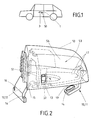
- FIG. 1 is schematically illustrated a motor vehicle, on the door 1, a handle is provided which has a door handle 3 on the outside. Laterally to the door handle 3, a protective cap 50 is arranged. Behind the protective cap 50, for example, a lock cylinder can be hidden, into which a key can be inserted manually in order to unlock or lock a lock of the door 1. This lock is not explicitly shown.
- FIG. 2 to FIG. 4 the area of the handle is shown on which the protective cap 50 is positioned.
- the protective cap 50 is detachably fastened to a securing element 10.
- the securing element 10 has different areas, so that this securing element 10 acts as a multi-functional component within the handle.
- the securing element 10 extends at least partially on the outer lining, in particular on the door panel 4 of the door 1.
- the securing element 10 is designed with an opening 13 in which a purely schematically illustrated lock cylinder 30 (see FIG. 4 ) is included.
- the lock cylinder is flush with the surface 18 of the securing element 10th
- the securing element 10 has an angled arm 11 which extends through an opening of the outer lining 4 of the door 1 and thus ends the door 1 on the inside.
- the arm 11 is angled and comprises a mounting portion 14, which is aligned in the present embodiment at an angle ⁇ to the outer panel 4, wherein the angle ⁇ is approximately between 20 ° and 30 °.
- the fastening portion 14 also has an opening 19 through which a fastening means 40 extends.
- the fastening means 40 is a screw element in the present exemplary embodiment. This screw member 40 connects the fuse element 10 with a support 2 of the handle, which extends inside the door 1.
- the carrier 2 of the handle has different functions, wherein in particular the carrier 2 may have a bearing point for the movable handle 3, which is not shown in detail.
- the carrier 2 extends longitudinally to the vehicle direction within the door 1 and, as mentioned above, depending on the type of handle further functions, which will be disregarded in detail below.
- the carrier 2 can be fastened via the fastening means 40 on the securing element 10, whereby ultimately the carrier 2 can be reliably fixed to the inside of the door 1.
- the fastening means 40 is completely inside the door 1.
- the securing element 10 has a second arm 12, which extends like the first arm 11 in the interior of the door 1 itself.
- the second arm 12 is formed with two shoulder elements 16, on which the carrier 2 is supported.
- a corresponding tightening of the screw member 40 takes place on the first arm 11 of the securing element 10, wherein at the same time the second arm 12 contacts the carrier 2 until it comes to reliable clamping on the shoulder element 16.
- the securing element 10 is reliably fixed to the door 1, wherein at the same time the inner support 2 is fixed inside the door 1.
- the securing element 10 has two fastening elements 15 in the form of openings 15, projecting into the locking elements 51 of the protective cap 50.
- the protective cap 50 is connected via a latching connection with the securing element 10.
- the protective cap 50 comprises a window 52, which is arranged laterally on the protective cap 50.
- the locking elements 51 are located inside the protective cap 50 in a cavity 53 which is formed by the protective cap 50.
- the locking elements 51 include projections 54 which can be actuated by an aid, such as an emergency key, to the locking elements 51 from their in the FIG. 2 to FIG. 4 to solve the set locking position.
- the projections 54 are chamfered according to the illustrated embodiment, so that an elastic deformation of the locking elements 51 via the aid, which is feasible in the cavity 53, is favored.
- the positioning of the locking elements 51 within the cavity 53 and the window 52 on the protective cap 50 is such that upon insertion of an aid through the window 52 into the cavity 53, the projections 54 of both locking elements 51 are actuated and thus both locking elements 51 from its detent position to be moved. Subsequently, the protective cap 50 is made of its in FIG. 2 to FIG. 4 shown position of the fuse element 10 removable.
- the latching elements 51 have at their free end a nose-like projection 55, which ensures that the latching connection of the protective cap 50 is ensured on the securing element 10.
- the securing element 10 consists of a metallic material, here of a steel.
- a dummy can be used as an alternative to the lock cylinder 30, which is useful, for example, in a handle, which is used on the passenger door.
- the lock cylinder 30 has a housing 31, wherein the housing 31 comprises an extension 33 which extends in the direction of the first arm 11. Namely, the case 31 is also fixed to the first arm 11 via the attachment means 40 like the carrier 2.
- the illustrated embodiment shows that the housing 31 has a collar 32 which lies protectively in front of the fastening means 40.
- FIG. 1 to FIG. 4 shows a handle, which is characterized by an increased security against burglary. This is partly because the fastener 40 is completely within the door 1 itself.
- the angled first arm 11 contributes to the fact that a destruction of the fastener 40 is difficult in the context of a break-in attempt from the outside.
- the collar 32 additionally protects the fastener 40 from external manipulation.
- the latching element 51 acts with its projection 55 on the securing element 10, in particular on the opening 15 of the securing element 10.
- the latching element 51 according to FIG. 5 through the opening 15 of the securing element 10 extends and engages with its projection 55 on the door 1, 4 and thus represents a reliable latching connection.
- the protective cap 50 may be a 2-component component, wherein an outer body 56 is designed as a first element of the protective cap 50 and the latching elements 51 are provided as a second element of the protective cap 50, which in FIG. 2 and FIG. 3 is indicated schematically.
- the second element of the protective cap 50 is completely in FIG. 3 shown in FIG FIG. 2 the outer body 56 is shown and in dashed lines the second, inner element is indicated.
Landscapes
- Lock And Its Accessories (AREA)
Abstract
Description
- Die Erfindung betrifft eine Handhabe für ein bewegliches Teil eines Kraftfahrzeuges, insbesondere für eine Tür, Klappe, Hecklappe oder dergleichen, mit einem Sicherungselement, das zumindest teilweise an der Außenverkleidung des beweglichen Teils anordbar ist, und einem Träger, der innenseitig des beweglichen Teils anordbar ist und mittels eines Befestigungsmittels am Sicherungselement befestigt ist.
- Aus der
DE 10 2008 019 013.6 ist eine Vorrichtung zur Sicherung eines Schließzylinders offenbart, der an einem beweglichen Teil eines Kraftfahrzeuges befestigt ist. Hierbei ist ein Sicherungselement vorgesehen, das an der Außenverkleidung des beweglichen Teils verläuft und innenseitig des beweglichen Teils an einem Träger befestigt ist. Hierbei weist das Sicherungselement eine Öffnung auf, in der zumindest der Kopfbereich des Schließzylinders aufgenommen ist. Zudem weist das Sicherungselement an der Außenverkleidung des beweglichen Teils eine flach verlaufende Bauform auf, wobei das Sicherungselement mit dem Träger über ein von der Außenseite des beweglichen Teils nicht sichtbares Befestigungselement verbunden ist. Das Befestigungselement verläuft schräg zur Drehachse des Schließzylinders, wobei das Ende des Befestigungselements in das außenliegende Sicherungselement hineinragt. Da das Sicherungselement eine entsprechende Materialstärke aufweist, hat sich vorteilhafterweise gezeigt, dass diese Vorrichtung eine hohe Einbruchsicherheit aufweist. - Es ist Aufgabe der vorliegenden Erfindung, eine Handhabe zu schaffen, bei der die Einbruchsicherheit weiter erhöht werden kann, wobei gleichzeitig der Montageaufwand gering gehalten wird.
- Zur Lösung dieser Aufgabe wird eine Handhabe mit sämtlichen Merkmalen des Anspruches 1 vorgeschlagen. In den abhängigen Ansprüchen sind bevorzugte Weiterbildungen ausgeführt.
- Dazu ist erfindungsgemäß vorgesehen, dass das Sicherungselement derart ausgeführt ist, dass das Befestigungsmittel vollständig innenseitig des beweglichen Teils verbleibt, wodurch eine erhöhte Einbruchsicherheit erzielbar ist. Ein wesentlicher Kern der Erfindung ist es, dass die erfindungsgemäße Handhabe kaum Angriffspunkte bietet, um mit einem etwaigen Werkzeug an das Befestigungsmittel, welches komplett innenseitig des beweglichen Teils liegt, zu gelangen, um beispielsweise eine Zerstörung am Träger, am Befestigungsmittel oder an wesentlichen Bauteilen, die am Träger befestigt sind, zu bewirken. Vorteilhafterweise liegt der Träger gleichzeitig an der Innenseite des beweglichen Teils an, wobei das Befestigungsmittel, das die Verbindung zwischen dem Träger und dem Sicherungselement schafft, die eigentliche Fixierung für den Träger darstellt. Zweckmäßigerweise kann das Befestigungsmittel als ein Schraubenelement ausgeführt sein, welches für eine schnelle und zuverlässige Verbindung zwischen dem Träger und dem Sicherungselement innenseitig des beweglichen Teils sorgt. Da das Befestigungsmittel vollständig innerhalb des beweglichen Teils angeordnet ist, ist eine Manipulation von außen erschwert, insbesondere kann wirksam verhindert werden, dass über ein Lösen des Befestigungsmittels die Handhabe am beweglichen Teil des Kraftfahrzeuges manipuliert, bewegt, gelöst werden kann, um böswillig in das Kraftfahrzeug zu gelangen.
- In einer möglichen Ausführungsform der Erfindung kann das Sicherungselement eine Öffnung aufweisen, in der ein Schließzylinder aufnehmbar ist. Über den Schließzylinder kann beispielsweise ein Entriegelungsvorgang oder ein Verriegelungsvorgang des beweglichen Teils manuell erfolgen. Der Schließzylinder ist vorteilhafterweise in Wirkverbindung mit einem Schloss, welches dafür sorgt, das bewegliche Teil mechanisch zu verriegeln und/oder zu entriegeln. Die Verbindung zwischen dem Schließzylinder und dem Schloss kann z.B. über ein Gestänge, einen Bowdenzug oder aber auch elektronisch erfolgen.
- Um die Einbruchssicherheit weiter zu erhöhen, kann es von Vorteil sein, dass das Sicherungselement einen abgewinkelten ersten Arm aufweist, an dem das Befestigungsmittel angreift, wobei insbesondere der erste Arm einen Befestigungsabschnitt umfasst, an dem das Befestigungsmittel wirkt. Zudem kann es vorgesehen sein, dass der Befestigungsabschnitt über eine Öffnung verfügt, durch die das Befestigungsmittel hindurchragt, um das Sicherungselement mit dem Träger zuverlässig zu verbinden und zu fixieren. Der abgewinkelte erste Arm hat den Vorteil, dass ein Manipulationsversuch im Bereich des Befestigungsmittels weiter erschwert wird. In einer möglichen Ausführungsform der Erfindung liegt der Befestigungsabschnitt des ersten Arms unterhalb und beabstandet zum restlichen an der Außenverkleidung des beweglichen Teils liegenden Teil des Sicherungselementes, das zusätzlich einen wirkungsvollen Schutz für das Befestigungsmittel darstellt.
- Besonders vorteilhaft kann sein, dass der Befestigungsabschnitt in einem Winkel α zum an der Außenverkleidung liegenden Teil des Sicherungselementes ausgerichtet ist, wobei der Winkel α in einem Bereich zwischen ungefähr 0 ≤ α ≤ 75° liegt. Vorteilhafterweise ist der Befestigungsabschnitt zum Schließzylinder oder einem Dummy ausgerichtet, wobei der Dummy alternativ zum Schließzylinder in der Öffnung des Sicherungselementes aufgenommen sein kann. Vorteilhaft ist, wenn der Winkel zwischen 20° und 50° liegt, da es sich überraschenderweise gezeigt hat, dass die Montagefreundlichkeit erhöht werden kann. Bei einer, die Erfindung verbessernden Maßnahme kann das Sicherungselement zumindest ein Befestigungselement aufweisen, an dem eine Schutzkappe befestigt ist, die die Öffnung und/oder den Schließzylinder deckt. Die Schutzkappe verhindert wirksam, dass von außen, insbesondere in den Schließzylinder Schmutzpartikel, Feuchtigkeit etc. eindringen können. Die Schutzkappe ist in einer bevorzugten Ausführungsform der Erfindung schalenartig ausgeführt, wobei im befestigen Zustand am Sicherungselement unterhalb der Schutzkappe sich ein Hohlraum bildet.
- In einer möglichen Ausführungsform der Erfindung ist die Handhabe ein wesentlicher Bestandteil eines Systems mit einem mobilen ID-Geber für eine schlüssellose Aktivierung eines Zugangsberechtigungssystems eines Kraftfahrzeuges. Hierbei kann der ID-Geber mit einem passiven Zugangsberechtigungssystem, insbesondere einem Zugangs- und Fahrberechtigungssystem des Kraftfahrzeuges kommunizieren. Beispielsweise kann das Kraftfahrzeug und der ID-Geber einen oder mehrere Codes miteinander austauschen, wobei die Kommunikation zwischen dem ID-Geber und dem Kraftfahrzeug, insbesondere der Handhabe über ein Funksignal erfolgen kann. Insbesondere werden die Signale induktiv ausgesandt. Vorteilhafterweise können die Signale aus Sicherheitsgründen kryptologisch verschlüsselt sein. Die genannte Kommunikation kann manuell über Tastendruck auf dem ID-Geber oder über eine entsprechende Annäherung und/oder Berührung der Handhabe gestartet werden, alternativ ohne aktive Betätigung, also passiv gesteuert und gestartet werden. Damit das Kraftfahrzeug auch genutzt werden kann, wenn die Elektronik innerhalb des ID-Gebers oder kraftfahrzeugseitig ausfallen sollte, kann vorteilhafterweise die Schutzkappe lösbar am Sicherungselement befestigt sein. Für einen derartigen Fall kann ein mechanischer Notschlüssel, nachdem die Schutzkappe vom Sicherungselement entfernt wurde, in den Schließzylinder eingeführt werden, um eine entsprechende Entriegelung und/oder Verriegelung der Schließvorrichtung des beweglichen Teils zu bewirken. Der Notschlüssel ist vorteilhafterweise am ID-Geber angeordnet bzw. befestigt.
- Vorteilhafterweise kann die Schutzkappe eine Rastverbindung mit dem Sicherungselement aufweisen. Eine elegante und kompakte Lösung kann vorsehen, wenn die Rastverbindung der Schutzkappe innenseitig vorgesehen ist, so dass diese Rastverbindung vom Außenbereich des Kraftfahrzeuges verdeckt ist. In einer denkbaren Ausführungsform der Handhabe kann die Schutzkappe zumindest ein Fenster aufweisen, durch das ein Hilfsmittel manuell einbringbar ist, um die Rastverbindung zu lösen. Hierbei kann das Hilfsmittel beispielsweise der Notschlüssel sein, der an einem ID-Geber vorhanden ist. Vorteilhafterweise weist die Schutzkappe Rastelemente auf, die eine elastische Materialeigenschaft aufweisen, so dass das Hilfsmittel, nachdem es durch das Fenster geführt ist und genügend weit in den Hohlraum der Schutzkappe eingeführt wurde, auf die Rastelemente derart wirkt, dass diese aus ihrer Raststellung bewegt werden. Anschließend kann der Benutzer leichtgängig die Schutzkappe vom Sicherungselement entfernen.
- Damit die Einbruchsicherheit weiter erhöht wird, ist der Schließzylinder und/oder Dummy im Bereich der Öffnung des Sicherungselementes bündig zum Sicherungselement positioniert. Zudem ist es denkbar, dass der Kopfbereich des Schließzylinders zusätzlich aus einem verstärkten Material besteht, beispielsweise kann der Kopfbereich aus einem Metall mit einer erhöhten Widerstandsfähigkeit bestehen. Es ist denkbar, dass der Kopfbereich ein Bauteil aus einer Zinkdruckgusslegierung (wie Zamak) ist. Alternativ kann der Kopfbereich auch aus einem gehärteten Stahl oder einem verstärkten Kunststoff ausgeführt sein. Durch diese Maßnahme kann eine Erhöhung der Einbruchsicherheit geschaffen werden.
- Vorteilhafterweise kann das Sicherungselement aus einem metallischen Material ausgeführt sein, insbesondere aus einem Stahl bestehen, wobei insbesondere die Stärke S des Sicherungselementes zwischen ungefähr 0,5 mm ≤ S ≤ 3 mm liegt. Vorzugsweise ist das Sicherungselement ein Körper mit einer erhöhten mechanischen Widerstandsfähigkeit. Das Sicherungselement kann alternativ ein Körper aus einem verstärkten Kunststoff sein. Vorteilhafterweise ist das Sicherungselement aus einem gehärteten Stahl, Edelstahl oder aus einer Zinkdruckgusslegierung (wie z.B. Zamak) ausgeführt. Des Weiteren ist es denkbar, dass der Träger mit dem Schließzylinder vormontiert ist, die gemeinsam eine Baueinheit bilden, die innenseitig des beweglichen Teils befestigt ist.
- Es hat sich vorteilhafterweise gezeigt, dass das Sicherungselement einen zweiten Arm aufweist, der innenseitig des beweglichen Teils am Träger anliegt und/oder sich abstützt, insbesondere der zweite Arm Schulterelemente aufweist, die den Träger kontaktieren. Dieser zweite Arm ist wie der erste Arm als Fortsatz des Sicherungselementes ausgeführt, der sich in den Innenbereich des beweglichen Teils erstreckt und über eine geeignete Form- und/oder kraftschlüssige Verbindung am Träger gehalten sein kann. Gemäß der vorliegenden Erfindung kann es von Vorteil sein, wenn eine Befestigung des Trägers über das Befestigungsmittel am ersten Arm des Sicherungselementes erfolgt, wobei gleichzeitig während des Befestigungsvorgangs der Träger in Richtung der Innenseite des beweglichen Teils gedrückt, geklemmt wird und/oder das Sicherungselement mit seinem zweiten Arm am Träger derart ausrichtet, bis der zweite Arm den Träger fest kontaktiert. Somit ist es denkbar, dass der Träger am ersten Arm über das Befestigungsmittel befestigt ist. Gleichzeitig erfolgt eine form- und kraftschlüssige Verbindung des Trägers am zweiten Arm, wobei diese Verbindung beispielsweise eine Klemmverbindung sein kann.
- In einer die Erfindung verbessernden Maßnahme ist der Schließzylinder mit einem Gehäuse ausgeführt, wobei das Gehäuse derart ausgebildet ist, dass das Gehäuse durch das Befestigungsmittel am ersten Arm befestigt ist. Hierbei dient das Gehäuse als zusätzlicher Schutz für den innenliegenden Schließzylinder, der drehbar innerhalb des Gehäuses aufgenommen sein kann. Das Gehäuse kann einen Fortsatz aufweisen, der in Richtung des ersten Arms verläuft und dort am Befestigungsmittel zuverlässig fixierbar ist. Die erfindungsgemäße Gestalt des Gehäuses bewirkt, dass wenige Bauteile erforderlich sind, um eine zuverlässige Befestigung des Schließzylinders sowie des Schließzylindergehäuses zu gewährleisten. Der Befestigungsbereich des zweiten Arm wird gleichzeitig für eine Befestigung des Schließzylinders sowie des Schließzylindergehäuses ausgenutzt.
- Zudem ist es möglich, dass das Gehäuse einen angeformten Kragen aufweist, der das Befestigungsmittel schützt. Dieser Kragen ist vorteilhafterweise am Fortsatz des Schließzylindergehäuses angeformt, so dass ein zusätzlicher Schutz für das Befestigungsmittel geschaffen wird, welches sich hinter dem Kragen befindet.
- Damit die Schutzkappe zuverlässig am Sicherungselement gehalten ist, kann vorgesehen sein, dass das Sicherungselement zumindest eine Lagerstelle aufweist, an der die Schutzkappe anliegt. Ferner kann das Sicherungselement und/oder die Schutzkappe eine Dichtung aufweisen, um ein schädliches Eindringen von Partikeln, Feuchtigkeit etc. in die Innenseite des beweglichen Teils zu verhindern.
- Vorteilhaft kann sein, dass die Schutzkappe ein 2-Komponenten-Bauteil ist, wobei ein Außenkörper das erste Element und die Rastelemente das zweite Element der Schutzkappe sind. Vorteilhafterweise können sich die Materialeigenschaften, insbesondere bzgl. der Elastizität zwischen dem ersten Element und dem zweiten Element unterscheiden.
- Weitere Vorteile, Merkmale und Einzelheiten der Erfindung ergeben sich aus der nachfolgenden Beschreibung, in der unter Bezugnahme auf die Zeichnungen mehrere Ausführungsbeispiele der Erfindung im Einzelnen beschrieben sind. Dabei können die in den Ansprüchen und in der Beschreibung erwähnten Merkmale jeweils einzeln für sich oder in beliebiger Kombination erfindungswesentlich sein. Es zeigen:
- Figur 1
- eine rein schematische Darstellung eines Kraftfahrzeuges, an dem eine erfindungsgemäße Handhabe für eine Kraftfahrzeugtür dargestellt ist,
- Figur 2
- ein wesentlicher Bestandteil der in
Figur 1 gezeigten Handhabe mit einer Schutzkappe, die an einem Sicherungselement befestigt ist, - Figur 3
- eine Detailansicht der
Figur 2 , - Figur 4
- ein weiteres Ausführungsbeispiel in Schnittansicht und
- Figur 5
- eine Detailansicht eines weiteren Ausführungsbeispieles aus
Figur 4 . - In
Figur 1 ist schematisch ein Kraftfahrzeug dargestellt, an dessen Tür 1 eine Handhabe vorgesehen ist, die außenseitig einen Türgriff 3 aufweist. Seitlich zum Türgriff 3 ist eine Schutzkappe 50 angeordnet. Hinter der Schutzkappe 50 kann beispielsweise ein Schließzylinder verborgen sein, in den ein Schlüssel manuell einsetzbar ist, um eine Schloss der Tür 1 zu entriegeln bzw. zu verriegeln. Dieses Schloss ist explizit nicht dargestellt. GemäßFigur 2 bis Figur 4 ist der Bereich der Handhabe dargestellt, an dem die Schutzkappe 50 positioniert ist. Die Schutzkappe 50 ist lösbar an einem Sicherungselement 10 befestigt. Das Sicherungselement 10 weist unterschiedliche Bereiche auf, so dass dieses Sicherungselement 10 als Multifunktionsbauteil innerhalb der Handhabe wirkt. Das Sicherungselement 10 verläuft zumindest teilweise an der Außenverkleidung, insbesondere am Türblech 4 der Tür 1. Zudem ist das Sicherungselement 10 mit einer Öffnung 13 ausgeführt, in der ein rein schematisch dargestellter Schließzylinder 30 (sieheFigur 4 ) aufgenommen ist. Hierbei verläuft der Schließzylinder bündig zur Oberfläche 18 des Sicherungselementes 10. - Zudem weist das Sicherungselement 10 einen abgewinkelten Arm 11 auf, der durch eine Öffnung der Außenverkleidung 4 der Tür 1 sich erstreckt und somit innenseitig der Tür 1 endet. Der Arm 11 ist abgewinkelt und umfasst einen Befestigungsabschnitt 14, der im vorliegenden Ausführungsbeispiel in einem Winkel α zur Außenverkleidung 4 ausgerichtet ist, wobei der Winkel α ungefähr zwischen 20° und 30° liegt. Der Befestigungsabschnitt 14 weist zudem eine Öffnung 19 auf, durch die ein Befestigungsmittel 40 verläuft. Das Befestigungsmittel 40 ist im vorliegenden Ausführungsbeispiel ein Schraubenelement. Dieses Schraubenelement 40 verbindet das Sicherungselement 10 mit einem Träger 2 der Handhabe, der innenseitig der Tür 1 verläuft. Der Träger 2 der Handhabe hat unterschiedliche Funktionen, wobei insbesondere der Träger 2 eine Lagerstelle für den beweglichen Griff 3 aufweisen kann, welche im Detail nicht gezeigt ist. In der Regel verläuft der Träger 2 längs zur Fahrzeugrichtung innerhalb der Tür 1 und weist wie zuvor erwähnt, je nach Art der Handhabe weitere Funktionen auf, die im Folgenden im Detail außer Acht gelassen werden. Wie in
Figur 2 bis Figur 4 zu erkennen ist, lässt sich der Träger 2 über das Befestigungsmittel 40 am Sicherungselement 10 befestigen, wodurch letztendlich der Träger 2 zuverlässig an der Innenseite der Tür 1 fixiert werden kann. Wie inFigur 2 bis Figur 4 deutlich zu erkennen ist, befindet sich das Befestigungsmittel 40 vollständig innenseitig der Tür 1. Ferner weist das Sicherungselement 10 einen zweiten Arm 12 auf, der wie der erste Arm 11 in den Innenbereich der Tür 1 sich erstreckt. Der zweite Arm 12 ist mit zwei Schulterelementen 16 ausgebildet, an denen sich der Träger 2 stützt. Während der Montage der Handhabe erfolgt ein entsprechendes Festziehen des Schraubenelementes 40 am ersten Arm 11 des Sicherungselementes 10, wobei gleichzeitig der zweite Arm 12 den Träger 2 kontaktiert bis es zur zuverlässigen Klemmung am Schulterelement 16 kommt. Somit ist das Sicherungselement 10 zuverlässig an der Tür 1 befestigt, wobei gleichzeitig der innenliegende Träger 2 innenseitig der Tür 1 fixiert ist. - Wie die
Figur 2 bis Figur 4 verdeutlichen, weist das Sicherungselement 10 zwei Befestigungselemente 15 in Form von Öffnungen 15 auf, in die Rastelemente 51 der Schutzkappe 50 hineinragen. Gemäß dem dargestellten Ausführungsbeispiel ist nämlich die Schutzkappe 50 über eine Rastverbindung mit dem Sicherungselement 10 verbunden. - Ferner umfasst die Schutzkappe 50 ein Fenster 52, welches seitlich an der Schutzkappe 50 angeordnet ist. Die Rastelemente 51 befinden sich innenseitig der Schutzkappe 50 und zwar in einem Hohlraum 53, der durch die Schutzkappe 50 gebildet ist. Die Rastelemente 51 umfassen Vorsprünge 54, die durch ein Hilfsmittel, beispielsweise einen Notschlüssel, betätigt werden können, um die Rastelemente 51 aus ihrer in der
Figur 2 bis Figur 4 gestellten Raststellung zu lösen. Die Vorsprünge 54 sind gemäß dem dargestellten Ausführungsbeispiel angeschrägt, so dass eine elastische Verformung der Rastelemente 51 über das Hilfsmittel, das in den Hohlraum 53 führbar ist, begünstigt wird. Die Positionierung der Rastelemente 51 innerhalb des Hohlraumes 53 sowie des Fensters 52 an der Schutzkappe 50 ist derart, dass bei einer Einführung eines Hilfsmittels durch das Fenster 52 in den Hohlraum 53 die Vorsprünge 54 beider Rastelemente 51 betätigt werden und somit beide Rastelemente 51 aus ihrer Rastposition bewegt werden. Anschließend ist die Schutzkappe 50 aus ihrer inFigur 2 bis Figur 4 dargestellten Position vom Sicherungselement 10 entfernbar. Die Rastelemente 51 weisen an ihrem freien Ende einen nasenartigen Vorsprung 55 auf, der dafür sorgt, dass die Rastverbindung der Schutzkappe 50 am Sicherungselement 10 gewährleistet ist. - Das Sicherungselement 10 besteht aus einem metallischen Material, hier aus einem Stahl. In die Öffnung 13 ist alternativ zum Schließzylinder 30 ein Dummy einsetzbar, welches beispielsweise bei einer Handhabe sinnvoll ist, die an der Beifahrertür zum Einsatz kommt. Wie
Figur 2 besonders verdeutlicht, weist der Schließzylinder 30 ein Gehäuse 31 auf, wobei das Gehäuse 31 einen Fortsatz 33 umfasst, der in Richtung des ersten Arms 11 sich erstreckt. Das Gehäuse 31 ist nämlich ebenfalls wie der Träger 2 am ersten Arm 11 über das Befestigungsmittel 40 befestigt. Zudem zeigt das dargestellte Ausführungsbeispiel, dass das Gehäuse 31 einen Kragen 32 aufweist, der schützend vor dem Befestigungsmittel 40 liegt. - Das gezeigte Ausführungsbeispiel gemäß
Figur 1 bis Figur 4 zeigt eine Handhabe, die sich durch eine erhöhte Einbruchsicherheit auszeichnet. Dies liegt unter anderem daran, dass das Befestigungsmittel 40 vollständig innerhalb der Tür 1 sich befindet. Darüber hinaus trägt der abgewinkelte erste Arm 11 dazu bei, dass eine Zerstörung des Befestigungsmittels 40 im Rahmen eines Einbruchversuches von außen erschwert wird. Der Kragen 32 schützt zusätzlich das Befestigungsmittel 40 vor äußeren Manipulationen. - In
Figur 4 wird deutlich, dass das Rastelement 51 mit seinem Vorsprung 55 am Sicherungselement 10, insbesondere an der Öffnung 15 des Sicherungselementes 10 wirkt. Alternativ ist ebenfalls denkbar, dass das Rastelement 51 gemäßFigur 5 durch die Öffnung 15 des Sicherungselementes 10 sich erstreckt und mit seinem Vorsprung 55 an der Tür 1, 4 angreift und somit eine zuverlässige Rastverbindung darstellt. - Die Schutzkappe 50 kann ein 2-Komponenten-Bauteil sein, wobei ein Außenkörper 56 als erstes Element der Schutzkappe 50 ausgeführt ist und die Rastelemente 51 als zweites Element der Schutzkappe 50 vorgesehen sind, welches in
Figur 2 undFigur 3 schematisch angedeutet ist. Das zweite Element der Schutzkappe 50 ist vollständig inFigur 3 gezeigt, wobei inFigur 2 der Außenkörper 56 gezeigt ist und in gestrichelter Darstellung das zweite, innenliegende Element angedeutet ist. -
- 1
- bewegliches Teil, Tür
- 2
- Träger
- 3
- Griff
- 4
- Außenverkleidung, Tür
- 10
- Sicherungselement
- 11
- erster Arm
- 12
- zweiter Arm
- 13
- Öffnung
- 14
- Befestigungsabschnitt
- 15
- Befestigungselement für 51, Öffnung
- 16
- Schulterelement
- 17
- Lagerstelle
- 18
- Oberfläche
- 19
- Öffnung für 40
- 30
- Schließzylinder
- 31
- Gehäuse
- 32
- Kragen
- 33
- Fortsatz
- 40
- Befestigungsmittel
- 50
- Schutzkappe
- 51
- Rastelement
- 52
- Fenster
- 53
- Hohlraum
- 54
- Vorsprung für ein Hilfsmittel
- 55
- Vorsprung
Claims (15)
- Handhabe für ein bewegliches Teil (1) eines Kraftfahrzeuges, insbesondere für eine Tür, Klappe, Hecklappe oder dergleichen, mit
einem Sicherungselement (10), das zumindest teilweise an der Außenverkleidung des beweglichen Teils (1) anordbar ist, und einem Träger (2), der innenseitig des beweglichen Teils (1) anordbar ist und mittels eines Befestigungsmittels (40) am Sicherungselement (10) befestigt ist,
dadurch gekennzeichnet,
dass das Sicherungselement (10) derart ausgeführt ist, dass das Befestigungsmittel (40) vollständig innenseitig des beweglichen Teils (1) verbleibt, wodurch eine erhöhte Einbruchsicherheit erzielbar ist. - Handhabe nach Anspruch 1,
dadurch gekennzeichnet,
dass das Sicherungselement (10) eine Öffnung (13) aufweist, in der ein Schließzylinder (30) aufnehmbar ist. - Handhabe nach Anspruch 1 oder 2,
dadurch gekennzeichnet,
dass das Sicherungselement (10) einen abgewinkelten ersten Arm (11) aufweist, an dem das Befestigungsmittel (40) angreift, wobei insbesondere der erste Arm (11) einen Befestigungsabschnitt (14) umfasst, an dem das Befestigungsmittel (40) wirkt. - Handhabe nach Anspruch 3,
dadurch gekennzeichnet,
dass der Befestigungsabschnitt (14) in einem Winkel α zum an der Außenverkleidung liegenden Teil des Sicherungselementes (10) ausgerichtet ist, wobei der Winkel α in einem Bereich zwischen ungefähr 0 ≤ α ≤ 75° liegt. - Handhabe nach einem der vorhergehenden Ansprüche,
dadurch gekennzeichnet,
dass das Sicherungselement (10) zumindest ein Befestigungselement (15) aufweist, an dem eine Schutzkappe (50) befestigt ist, die die Öffnung (13) und/oder den Schließzylinder bedeckt. - Handhabe nach Anspruch 5,
dadurch gekennzeichnet,
dass die Schutzkappe (50) am Sicherungselement (10) lösbar befestigt ist. - Handhabe nach Anspruch 5 oder 6,
dadurch gekennzeichnet,
dass die Schutzkappe (50) eine Rastverbindung mit dem Sicherungselement (10) aufweist. - Handhabe nach Anspruch 7,
dadurch gekennzeichnet,
dass die Schutzkappe (50) zumindest ein Fenster (52) aufweist, durch das ein Hilfsmittel manuell einbringbar ist, um die Rastverbindung zu lösen. - Handhabe nach einem der vorhergehenden Ansprüche,
dadurch gekennzeichnet,
dass der Schließzylinder (30) und/oder ein Dummy in der Öffnung (13) sich befindet, wobei der Schließzylinder (30) und/oder der Dummy im Bereich der Öffnung (13) bündig zum Sicherungselement (10) positioniert ist. - Handhabe nach einem der vorhergehenden Ansprüche,
dadurch gekennzeichnet,
dass das Sicherungselement (10) aus einem metallischen Material ausgeführt ist, insbesondere aus einem Stahl besteht, wobei insbesondere die Stärke S des Sicherungselementes (10) zwischen ungefähr 0,5 mm ≤ S ≤ 3 mm liegt. - Handhabe nach einem der vorhergehenden Ansprüche,
dadurch gekennzeichnet,
dass das Sicherungselement (10) einen zweiten Arm (12) aufweist, der innenseitig des beweglichen Teils (1) am Träger (2) anliegt und/oder sich abstützt, insbesondere der zweite Arm (12) Schulterelemente (16) aufweist, die den Träger (2) kontaktieren. - Handhabe nach einem der vorhergehenden Ansprüche,
dadurch gekennzeichnet,
dass der Schließzylinder (30) mit einem Gehäuse (31) ausgeführt ist, wobei das Gehäuse (31) derart ausgebildet ist, dass das Gehäuse (31) durch das Befestigungsmittel (40) am ersten Arm (11) befestigt ist. - Handhabe nach Anspruch 12,
dadurch gekennzeichnet,
dass das Gehäuse (31) einen angeformten Kragen (32) aufweist, der das Befestigungsmittel (40) schützt. - Handhabe nach einem der vorhergehenden Ansprüche,
dadurch gekennzeichnet,
dass das Sicherungselement (10) zumindest eine Lagerstelle (17) aufweist, an der die Schutzkappe (50) anliegt. - Handhabe nach einem der vorhergehenden Ansprüche,
dadurch gekennzeichnet,
dass die Schutzkappe (50) ein 2-Komponenten-Bauteil ist, wobei ein Außenkörper (56) das erste Element und die Rastelemente (51) das zweite Element der Schutzkappe (50) sind.
Applications Claiming Priority (1)
| Application Number | Priority Date | Filing Date | Title |
|---|---|---|---|
| DE201110002287 DE102011002287A1 (de) | 2011-04-27 | 2011-04-27 | Handhabe mit einem Sicherungselement, dessen Befestigungsmittel vollständig innenseitig eines beweglichen Teils verbleibt |
Publications (3)
| Publication Number | Publication Date |
|---|---|
| EP2518245A2 true EP2518245A2 (de) | 2012-10-31 |
| EP2518245A3 EP2518245A3 (de) | 2014-04-30 |
| EP2518245B1 EP2518245B1 (de) | 2017-09-13 |
Family
ID=46022024
Family Applications (1)
| Application Number | Title | Priority Date | Filing Date |
|---|---|---|---|
| EP12162429.0A Active EP2518245B1 (de) | 2011-04-27 | 2012-03-30 | Handhabe mit einem Sicherungselement, dessen Befestigungsmittel vollständig innenseitig eines beweglichen Teils verbleibt |
Country Status (4)
| Country | Link |
|---|---|
| US (1) | US9260892B2 (de) |
| EP (1) | EP2518245B1 (de) |
| CN (1) | CN102758559B (de) |
| DE (1) | DE102011002287A1 (de) |
Cited By (4)
| Publication number | Priority date | Publication date | Assignee | Title |
|---|---|---|---|---|
| WO2016037604A1 (de) * | 2014-09-08 | 2016-03-17 | Huf Hülsbeck & Fürst Gmbh & Co. Kg | TÜRAUßENGRIFF FÜR KRAFTFAHRZEUG |
| FR3026131A1 (fr) * | 2014-09-23 | 2016-03-25 | Mgi Coutier Espana Sl | Dispositif de blocage de poignee de portiere cachee avec deblocage manuel d’urgence |
| DE102015008122A1 (de) * | 2015-06-24 | 2016-12-29 | Audi Ag | Elektrische Türaußenbetätigung für eine Fahrzeugtür |
| EP3128108A1 (de) * | 2015-08-06 | 2017-02-08 | Huf Hülsbeck & Fürst GmbH & Co. KG | Griffeinheit |
Families Citing this family (8)
| Publication number | Priority date | Publication date | Assignee | Title |
|---|---|---|---|---|
| DE102009045843A1 (de) * | 2009-10-20 | 2011-04-21 | Huf Hülsbeck & Fürst Gmbh & Co. Kg | Griffvorrichtung |
| DE202013009474U1 (de) * | 2013-10-25 | 2015-01-26 | GM Global Technology Operations, LLC (n.d. Ges. d. Staates Delaware) | Klammereinrichtung, Schließzylindervorrichtung und Kraftfahrzeug |
| US9873387B2 (en) * | 2013-12-27 | 2018-01-23 | Huf North America Automotive Parts Mfg. Corp. | Vehicle closure release with attached deployable camera |
| JP6612686B2 (ja) * | 2016-06-21 | 2019-11-27 | 株式会社ホンダロック | 車両用ドアのアウトハンドル装置 |
| US10246901B2 (en) * | 2017-03-17 | 2019-04-02 | GM Global Technology Operations LLC | Lock assembly with removable cover |
| DE102017126032B4 (de) * | 2017-11-08 | 2025-11-13 | Dr. Ing. H.C. F. Porsche Aktiengesellschaft | Schließvorrichtung |
| FR3081489B1 (fr) * | 2018-05-25 | 2022-09-09 | U Shin Italia Spa | Dispositif de poignee d’ouvrant, notamment pour vehicule |
| CN118273592A (zh) * | 2023-10-12 | 2024-07-02 | 比亚迪股份有限公司 | 用于车门的闭锁机构、车门以及车辆 |
Citations (1)
| Publication number | Priority date | Publication date | Assignee | Title |
|---|---|---|---|---|
| DE102008019013A1 (de) | 2008-04-15 | 2009-10-22 | Huf Hülsbeck & Fürst Gmbh & Co. Kg | Vorrichtung zur Sicherung eines Schließzylinders |
Family Cites Families (11)
| Publication number | Priority date | Publication date | Assignee | Title |
|---|---|---|---|---|
| US2102714A (en) * | 1936-09-05 | 1937-12-21 | Keeler Brass Co | Door handle mounting |
| US2647783A (en) * | 1950-03-13 | 1953-08-04 | Keeler Brass Co | Latch releasing door handle |
| GB8701875D0 (en) * | 1987-01-28 | 1987-03-04 | Rolls Royce Motor Cars | Handle assembly |
| US5477712A (en) * | 1993-10-21 | 1995-12-26 | Hill International | Automobile anit-theft guard plate |
| US5706554A (en) * | 1994-12-02 | 1998-01-13 | Ewald Witte Gmbh & Co. Kg | Handle fitting, which can be inserted into an opening in a door, particularly a motor-vehicle door |
| CN2329729Y (zh) * | 1998-07-31 | 1999-07-21 | 吴生田 | 一种汽车门把手 |
| EP1277900B1 (de) * | 2001-07-20 | 2007-01-03 | Valeo Sicurezza Abitacolo S.p.A. | Türgriff für ein Kraftfahrzeug |
| DE10336764B4 (de) * | 2003-08-08 | 2015-08-13 | Huf Hülsbeck & Fürst GmbH & Co KG | Vorrichtung zur Betätigung eines Schlosses |
| ITMI20061643A1 (it) * | 2006-08-25 | 2008-02-26 | Valco Sicurezza Abitacolo S P | Maniglia per portiera di autoveicolo con cappuccio amovibile per il blocchetto della serratura |
| DE102008031218B4 (de) * | 2008-07-03 | 2014-10-30 | Huf Hülsbeck & Fürst Gmbh & Co. Kg | Griffeinheit für ein Kraftfahrzeug |
| MY177879A (en) * | 2010-11-26 | 2020-09-24 | Honda Motor Co Ltd | Opening/closing operation device for vehicle open/close door |
-
2011
- 2011-04-27 DE DE201110002287 patent/DE102011002287A1/de not_active Withdrawn
-
2012
- 2012-03-30 EP EP12162429.0A patent/EP2518245B1/de active Active
- 2012-04-20 CN CN201210118718.1A patent/CN102758559B/zh not_active Expired - Fee Related
- 2012-04-25 US US13/455,729 patent/US9260892B2/en not_active Expired - Fee Related
Patent Citations (1)
| Publication number | Priority date | Publication date | Assignee | Title |
|---|---|---|---|---|
| DE102008019013A1 (de) | 2008-04-15 | 2009-10-22 | Huf Hülsbeck & Fürst Gmbh & Co. Kg | Vorrichtung zur Sicherung eines Schließzylinders |
Cited By (6)
| Publication number | Priority date | Publication date | Assignee | Title |
|---|---|---|---|---|
| WO2016037604A1 (de) * | 2014-09-08 | 2016-03-17 | Huf Hülsbeck & Fürst Gmbh & Co. Kg | TÜRAUßENGRIFF FÜR KRAFTFAHRZEUG |
| FR3026131A1 (fr) * | 2014-09-23 | 2016-03-25 | Mgi Coutier Espana Sl | Dispositif de blocage de poignee de portiere cachee avec deblocage manuel d’urgence |
| DE102015008122A1 (de) * | 2015-06-24 | 2016-12-29 | Audi Ag | Elektrische Türaußenbetätigung für eine Fahrzeugtür |
| DE102015008122B4 (de) | 2015-06-24 | 2024-09-26 | Audi Ag | Elektrische Türaußenbetätigung für eine Fahrzeugtür |
| EP3128108A1 (de) * | 2015-08-06 | 2017-02-08 | Huf Hülsbeck & Fürst GmbH & Co. KG | Griffeinheit |
| US9708831B2 (en) | 2015-08-06 | 2017-07-18 | Huf Huelsbeck & Fuerst Gmbh & Co. Kg | Handle unit |
Also Published As
| Publication number | Publication date |
|---|---|
| CN102758559A (zh) | 2012-10-31 |
| EP2518245B1 (de) | 2017-09-13 |
| DE102011002287A1 (de) | 2012-10-31 |
| US9260892B2 (en) | 2016-02-16 |
| EP2518245A3 (de) | 2014-04-30 |
| CN102758559B (zh) | 2018-05-11 |
| US20120274088A1 (en) | 2012-11-01 |
Similar Documents
| Publication | Publication Date | Title |
|---|---|---|
| EP2518245B1 (de) | Handhabe mit einem Sicherungselement, dessen Befestigungsmittel vollständig innenseitig eines beweglichen Teils verbleibt | |
| DE102009045843A1 (de) | Griffvorrichtung | |
| EP2562338B1 (de) | Türgriffanordnung eines Kraftfahrzeugs | |
| DE19724573C2 (de) | Abdeckeinrichtung für einen Schließzylinder, insbesondere an einer Fahrzeugtür | |
| DE102018202563A1 (de) | Knauf für einen elektronischen Schließzylinder | |
| DE10144166B4 (de) | Schloss für eine Kraftfahrzeugtür | |
| EP2642049B1 (de) | Handhabe eines Kraftfahrzeuges mit einem bewegbaren Abdeckelement | |
| DE102009044598B4 (de) | Verriegelungsvorrichtung eines Kraftfahrzeugs | |
| DE19955693C2 (de) | Kraftfahrzeugtürverschluss | |
| DE102016111837A1 (de) | Kraftfahrzeugschloss | |
| DE102008019013B4 (de) | Vorrichtung zur Sicherung eines Schließzylinders | |
| DE19649688A1 (de) | Schlüssel | |
| DE19827132B4 (de) | Außengriffanordnung für eine Kraftfahrzeugtür | |
| EP3775449A1 (de) | Griffvorrichtung für eine tür oder eine klappe | |
| DE10017559B4 (de) | Schließvorrichtung | |
| EP1069010B1 (de) | Kraftfahrzeug-Lenkradschloss | |
| EP3775450A1 (de) | Griffvorrichtung | |
| EP1580354A2 (de) | Beschlag | |
| EP1333134A2 (de) | Schliesszylinder | |
| EP4509681A1 (de) | Zylinderschloss | |
| DE102016006374B4 (de) | Sicherheitseinrichtung für ein Kfz-Türschloss und Kfz-Türschloss | |
| DE102012025061A1 (de) | Gehäuse, insbesondere für einen elektronischen Schlüssel | |
| DE102021111345A1 (de) | Anbindung eines Bowdenzugs an ein Kraftfahrzeugschloss | |
| DE102012107950A1 (de) | Mobiler Identifikationsgeber | |
| DE202007006628U1 (de) | Türschloßschutzvorrichtung |
Legal Events
| Date | Code | Title | Description |
|---|---|---|---|
| PUAI | Public reference made under article 153(3) epc to a published international application that has entered the european phase |
Free format text: ORIGINAL CODE: 0009012 |
|
| AK | Designated contracting states |
Kind code of ref document: A2 Designated state(s): AL AT BE BG CH CY CZ DE DK EE ES FI FR GB GR HR HU IE IS IT LI LT LU LV MC MK MT NL NO PL PT RO RS SE SI SK SM TR |
|
| AX | Request for extension of the european patent |
Extension state: BA ME |
|
| PUAL | Search report despatched |
Free format text: ORIGINAL CODE: 0009013 |
|
| AK | Designated contracting states |
Kind code of ref document: A3 Designated state(s): AL AT BE BG CH CY CZ DE DK EE ES FI FR GB GR HR HU IE IS IT LI LT LU LV MC MK MT NL NO PL PT RO RS SE SI SK SM TR |
|
| AX | Request for extension of the european patent |
Extension state: BA ME |
|
| RIC1 | Information provided on ipc code assigned before grant |
Ipc: E05B 77/44 20140101ALI20140321BHEP Ipc: E05B 85/16 20140101ALN20140321BHEP Ipc: E05B 85/06 20140101ALI20140321BHEP Ipc: E05B 79/06 20140101ALI20140321BHEP Ipc: E05B 17/00 20060101ALI20140321BHEP Ipc: E05B 79/02 20140101ALI20140321BHEP Ipc: E05B 17/14 20060101ALN20140321BHEP Ipc: E05B 81/90 20140101ALN20140321BHEP Ipc: E05B 15/16 20060101AFI20140321BHEP |
|
| 17P | Request for examination filed |
Effective date: 20141030 |
|
| RAX | Requested extension states of the european patent have changed |
Extension state: BA Payment date: 20141030 Extension state: ME Payment date: 20141030 |
|
| RBV | Designated contracting states (corrected) |
Designated state(s): AL AT BE BG CH CY CZ DE DK EE ES FI FR GB GR HR HU IE IS IT LI LT LU LV MC MK MT NL NO PL PT RO RS SE SI SK SM TR |
|
| GRAP | Despatch of communication of intention to grant a patent |
Free format text: ORIGINAL CODE: EPIDOSNIGR1 |
|
| STAA | Information on the status of an ep patent application or granted ep patent |
Free format text: STATUS: GRANT OF PATENT IS INTENDED |
|
| RIC1 | Information provided on ipc code assigned before grant |
Ipc: E05B 79/02 20140101ALI20170109BHEP Ipc: E05B 77/44 20140101ALI20170109BHEP Ipc: E05B 17/14 20060101ALN20170109BHEP Ipc: E05B 85/16 20140101ALN20170109BHEP Ipc: E05B 85/06 20140101ALI20170109BHEP Ipc: E05B 79/06 20140101ALI20170109BHEP Ipc: E05B 81/90 20140101ALN20170109BHEP Ipc: E05B 77/34 20140101AFI20170109BHEP |
|
| INTG | Intention to grant announced |
Effective date: 20170207 |
|
| GRAJ | Information related to disapproval of communication of intention to grant by the applicant or resumption of examination proceedings by the epo deleted |
Free format text: ORIGINAL CODE: EPIDOSDIGR1 |
|
| REG | Reference to a national code |
Ref country code: DE Ref legal event code: R079 Ref document number: 502012011242 Country of ref document: DE Free format text: PREVIOUS MAIN CLASS: E05B0065200000 Ipc: E05B0077340000 |
|
| STAA | Information on the status of an ep patent application or granted ep patent |
Free format text: STATUS: REQUEST FOR EXAMINATION WAS MADE |
|
| GRAP | Despatch of communication of intention to grant a patent |
Free format text: ORIGINAL CODE: EPIDOSNIGR1 |
|
| STAA | Information on the status of an ep patent application or granted ep patent |
Free format text: STATUS: GRANT OF PATENT IS INTENDED |
|
| INTC | Intention to grant announced (deleted) | ||
| INTG | Intention to grant announced |
Effective date: 20170531 |
|
| RIC1 | Information provided on ipc code assigned before grant |
Ipc: E05B 17/14 20060101ALN20170519BHEP Ipc: E05B 79/02 20140101ALI20170519BHEP Ipc: E05B 81/90 20140101ALN20170519BHEP Ipc: E05B 85/06 20140101ALI20170519BHEP Ipc: E05B 77/44 20140101ALI20170519BHEP Ipc: E05B 85/16 20140101ALN20170519BHEP Ipc: E05B 79/06 20140101ALI20170519BHEP Ipc: E05B 77/34 20140101AFI20170519BHEP |
|
| GRAS | Grant fee paid |
Free format text: ORIGINAL CODE: EPIDOSNIGR3 |
|
| GRAA | (expected) grant |
Free format text: ORIGINAL CODE: 0009210 |
|
| STAA | Information on the status of an ep patent application or granted ep patent |
Free format text: STATUS: THE PATENT HAS BEEN GRANTED |
|
| AK | Designated contracting states |
Kind code of ref document: B1 Designated state(s): AL AT BE BG CH CY CZ DE DK EE ES FI FR GB GR HR HU IE IS IT LI LT LU LV MC MK MT NL NO PL PT RO RS SE SI SK SM TR |
|
| AX | Request for extension of the european patent |
Extension state: BA ME |
|
| REG | Reference to a national code |
Ref country code: GB Ref legal event code: FG4D Free format text: NOT ENGLISH |
|
| REG | Reference to a national code |
Ref country code: CH Ref legal event code: EP |
|
| REG | Reference to a national code |
Ref country code: IE Ref legal event code: FG4D Free format text: LANGUAGE OF EP DOCUMENT: GERMAN |
|
| REG | Reference to a national code |
Ref country code: AT Ref legal event code: REF Ref document number: 928319 Country of ref document: AT Kind code of ref document: T Effective date: 20171015 |
|
| REG | Reference to a national code |
Ref country code: DE Ref legal event code: R096 Ref document number: 502012011242 Country of ref document: DE |
|
| REG | Reference to a national code |
Ref country code: NL Ref legal event code: MP Effective date: 20170913 |
|
| REG | Reference to a national code |
Ref country code: LT Ref legal event code: MG4D |
|
| PG25 | Lapsed in a contracting state [announced via postgrant information from national office to epo] |
Ref country code: SE Free format text: LAPSE BECAUSE OF FAILURE TO SUBMIT A TRANSLATION OF THE DESCRIPTION OR TO PAY THE FEE WITHIN THE PRESCRIBED TIME-LIMIT Effective date: 20170913 Ref country code: NO Free format text: LAPSE BECAUSE OF FAILURE TO SUBMIT A TRANSLATION OF THE DESCRIPTION OR TO PAY THE FEE WITHIN THE PRESCRIBED TIME-LIMIT Effective date: 20171213 Ref country code: LT Free format text: LAPSE BECAUSE OF FAILURE TO SUBMIT A TRANSLATION OF THE DESCRIPTION OR TO PAY THE FEE WITHIN THE PRESCRIBED TIME-LIMIT Effective date: 20170913 Ref country code: FI Free format text: LAPSE BECAUSE OF FAILURE TO SUBMIT A TRANSLATION OF THE DESCRIPTION OR TO PAY THE FEE WITHIN THE PRESCRIBED TIME-LIMIT Effective date: 20170913 Ref country code: HR Free format text: LAPSE BECAUSE OF FAILURE TO SUBMIT A TRANSLATION OF THE DESCRIPTION OR TO PAY THE FEE WITHIN THE PRESCRIBED TIME-LIMIT Effective date: 20170913 |
|
| PG25 | Lapsed in a contracting state [announced via postgrant information from national office to epo] |
Ref country code: ES Free format text: LAPSE BECAUSE OF FAILURE TO SUBMIT A TRANSLATION OF THE DESCRIPTION OR TO PAY THE FEE WITHIN THE PRESCRIBED TIME-LIMIT Effective date: 20170913 Ref country code: RS Free format text: LAPSE BECAUSE OF FAILURE TO SUBMIT A TRANSLATION OF THE DESCRIPTION OR TO PAY THE FEE WITHIN THE PRESCRIBED TIME-LIMIT Effective date: 20170913 Ref country code: BG Free format text: LAPSE BECAUSE OF FAILURE TO SUBMIT A TRANSLATION OF THE DESCRIPTION OR TO PAY THE FEE WITHIN THE PRESCRIBED TIME-LIMIT Effective date: 20171213 Ref country code: LV Free format text: LAPSE BECAUSE OF FAILURE TO SUBMIT A TRANSLATION OF THE DESCRIPTION OR TO PAY THE FEE WITHIN THE PRESCRIBED TIME-LIMIT Effective date: 20170913 Ref country code: GR Free format text: LAPSE BECAUSE OF FAILURE TO SUBMIT A TRANSLATION OF THE DESCRIPTION OR TO PAY THE FEE WITHIN THE PRESCRIBED TIME-LIMIT Effective date: 20171214 |
|
| REG | Reference to a national code |
Ref country code: FR Ref legal event code: PLFP Year of fee payment: 7 |
|
| PG25 | Lapsed in a contracting state [announced via postgrant information from national office to epo] |
Ref country code: NL Free format text: LAPSE BECAUSE OF FAILURE TO SUBMIT A TRANSLATION OF THE DESCRIPTION OR TO PAY THE FEE WITHIN THE PRESCRIBED TIME-LIMIT Effective date: 20170913 |
|
| PG25 | Lapsed in a contracting state [announced via postgrant information from national office to epo] |
Ref country code: PL Free format text: LAPSE BECAUSE OF FAILURE TO SUBMIT A TRANSLATION OF THE DESCRIPTION OR TO PAY THE FEE WITHIN THE PRESCRIBED TIME-LIMIT Effective date: 20170913 Ref country code: CZ Free format text: LAPSE BECAUSE OF FAILURE TO SUBMIT A TRANSLATION OF THE DESCRIPTION OR TO PAY THE FEE WITHIN THE PRESCRIBED TIME-LIMIT Effective date: 20170913 Ref country code: RO Free format text: LAPSE BECAUSE OF FAILURE TO SUBMIT A TRANSLATION OF THE DESCRIPTION OR TO PAY THE FEE WITHIN THE PRESCRIBED TIME-LIMIT Effective date: 20170913 |
|
| PG25 | Lapsed in a contracting state [announced via postgrant information from national office to epo] |
Ref country code: SK Free format text: LAPSE BECAUSE OF FAILURE TO SUBMIT A TRANSLATION OF THE DESCRIPTION OR TO PAY THE FEE WITHIN THE PRESCRIBED TIME-LIMIT Effective date: 20170913 Ref country code: SM Free format text: LAPSE BECAUSE OF FAILURE TO SUBMIT A TRANSLATION OF THE DESCRIPTION OR TO PAY THE FEE WITHIN THE PRESCRIBED TIME-LIMIT Effective date: 20170913 Ref country code: IT Free format text: LAPSE BECAUSE OF FAILURE TO SUBMIT A TRANSLATION OF THE DESCRIPTION OR TO PAY THE FEE WITHIN THE PRESCRIBED TIME-LIMIT Effective date: 20170913 Ref country code: EE Free format text: LAPSE BECAUSE OF FAILURE TO SUBMIT A TRANSLATION OF THE DESCRIPTION OR TO PAY THE FEE WITHIN THE PRESCRIBED TIME-LIMIT Effective date: 20170913 Ref country code: IS Free format text: LAPSE BECAUSE OF FAILURE TO SUBMIT A TRANSLATION OF THE DESCRIPTION OR TO PAY THE FEE WITHIN THE PRESCRIBED TIME-LIMIT Effective date: 20180113 |
|
| REG | Reference to a national code |
Ref country code: DE Ref legal event code: R097 Ref document number: 502012011242 Country of ref document: DE |
|
| PLBE | No opposition filed within time limit |
Free format text: ORIGINAL CODE: 0009261 |
|
| STAA | Information on the status of an ep patent application or granted ep patent |
Free format text: STATUS: NO OPPOSITION FILED WITHIN TIME LIMIT |
|
| PG25 | Lapsed in a contracting state [announced via postgrant information from national office to epo] |
Ref country code: DK Free format text: LAPSE BECAUSE OF FAILURE TO SUBMIT A TRANSLATION OF THE DESCRIPTION OR TO PAY THE FEE WITHIN THE PRESCRIBED TIME-LIMIT Effective date: 20170913 |
|
| 26N | No opposition filed |
Effective date: 20180614 |
|
| PG25 | Lapsed in a contracting state [announced via postgrant information from national office to epo] |
Ref country code: MT Free format text: LAPSE BECAUSE OF FAILURE TO SUBMIT A TRANSLATION OF THE DESCRIPTION OR TO PAY THE FEE WITHIN THE PRESCRIBED TIME-LIMIT Effective date: 20170913 |
|
| REG | Reference to a national code |
Ref country code: CH Ref legal event code: PL |
|
| GBPC | Gb: european patent ceased through non-payment of renewal fee |
Effective date: 20180330 |
|
| PG25 | Lapsed in a contracting state [announced via postgrant information from national office to epo] |
Ref country code: SI Free format text: LAPSE BECAUSE OF FAILURE TO SUBMIT A TRANSLATION OF THE DESCRIPTION OR TO PAY THE FEE WITHIN THE PRESCRIBED TIME-LIMIT Effective date: 20170913 Ref country code: MC Free format text: LAPSE BECAUSE OF FAILURE TO SUBMIT A TRANSLATION OF THE DESCRIPTION OR TO PAY THE FEE WITHIN THE PRESCRIBED TIME-LIMIT Effective date: 20170913 |
|
| REG | Reference to a national code |
Ref country code: BE Ref legal event code: MM Effective date: 20180331 |
|
| REG | Reference to a national code |
Ref country code: IE Ref legal event code: MM4A |
|
| PG25 | Lapsed in a contracting state [announced via postgrant information from national office to epo] |
Ref country code: LU Free format text: LAPSE BECAUSE OF NON-PAYMENT OF DUE FEES Effective date: 20180330 |
|
| PG25 | Lapsed in a contracting state [announced via postgrant information from national office to epo] |
Ref country code: IE Free format text: LAPSE BECAUSE OF NON-PAYMENT OF DUE FEES Effective date: 20180330 |
|
| PG25 | Lapsed in a contracting state [announced via postgrant information from national office to epo] |
Ref country code: GB Free format text: LAPSE BECAUSE OF NON-PAYMENT OF DUE FEES Effective date: 20180330 Ref country code: BE Free format text: LAPSE BECAUSE OF NON-PAYMENT OF DUE FEES Effective date: 20180331 Ref country code: CH Free format text: LAPSE BECAUSE OF NON-PAYMENT OF DUE FEES Effective date: 20180331 Ref country code: LI Free format text: LAPSE BECAUSE OF NON-PAYMENT OF DUE FEES Effective date: 20180331 |
|
| REG | Reference to a national code |
Ref country code: AT Ref legal event code: MM01 Ref document number: 928319 Country of ref document: AT Kind code of ref document: T Effective date: 20180330 |
|
| PG25 | Lapsed in a contracting state [announced via postgrant information from national office to epo] |
Ref country code: AT Free format text: LAPSE BECAUSE OF NON-PAYMENT OF DUE FEES Effective date: 20180330 |
|
| PG25 | Lapsed in a contracting state [announced via postgrant information from national office to epo] |
Ref country code: TR Free format text: LAPSE BECAUSE OF FAILURE TO SUBMIT A TRANSLATION OF THE DESCRIPTION OR TO PAY THE FEE WITHIN THE PRESCRIBED TIME-LIMIT Effective date: 20170913 |
|
| PG25 | Lapsed in a contracting state [announced via postgrant information from national office to epo] |
Ref country code: PT Free format text: LAPSE BECAUSE OF FAILURE TO SUBMIT A TRANSLATION OF THE DESCRIPTION OR TO PAY THE FEE WITHIN THE PRESCRIBED TIME-LIMIT Effective date: 20170913 Ref country code: HU Free format text: LAPSE BECAUSE OF FAILURE TO SUBMIT A TRANSLATION OF THE DESCRIPTION OR TO PAY THE FEE WITHIN THE PRESCRIBED TIME-LIMIT; INVALID AB INITIO Effective date: 20120330 |
|
| PG25 | Lapsed in a contracting state [announced via postgrant information from national office to epo] |
Ref country code: CY Free format text: LAPSE BECAUSE OF FAILURE TO SUBMIT A TRANSLATION OF THE DESCRIPTION OR TO PAY THE FEE WITHIN THE PRESCRIBED TIME-LIMIT Effective date: 20170913 Ref country code: MK Free format text: LAPSE BECAUSE OF NON-PAYMENT OF DUE FEES Effective date: 20170913 |
|
| PG25 | Lapsed in a contracting state [announced via postgrant information from national office to epo] |
Ref country code: AL Free format text: LAPSE BECAUSE OF FAILURE TO SUBMIT A TRANSLATION OF THE DESCRIPTION OR TO PAY THE FEE WITHIN THE PRESCRIBED TIME-LIMIT Effective date: 20170913 |
|
| PGFP | Annual fee paid to national office [announced via postgrant information from national office to epo] |
Ref country code: DE Payment date: 20210331 Year of fee payment: 10 |
|
| PGFP | Annual fee paid to national office [announced via postgrant information from national office to epo] |
Ref country code: FR Payment date: 20220323 Year of fee payment: 11 |
|
| REG | Reference to a national code |
Ref country code: DE Ref legal event code: R119 Ref document number: 502012011242 Country of ref document: DE |
|
| PG25 | Lapsed in a contracting state [announced via postgrant information from national office to epo] |
Ref country code: DE Free format text: LAPSE BECAUSE OF NON-PAYMENT OF DUE FEES Effective date: 20221001 |
|
| P01 | Opt-out of the competence of the unified patent court (upc) registered |
Effective date: 20230426 |
|
| PG25 | Lapsed in a contracting state [announced via postgrant information from national office to epo] |
Ref country code: FR Free format text: LAPSE BECAUSE OF NON-PAYMENT OF DUE FEES Effective date: 20230331 |