EP1580354A2 - Beschlag - Google Patents
Beschlag Download PDFInfo
- Publication number
- EP1580354A2 EP1580354A2 EP05100767A EP05100767A EP1580354A2 EP 1580354 A2 EP1580354 A2 EP 1580354A2 EP 05100767 A EP05100767 A EP 05100767A EP 05100767 A EP05100767 A EP 05100767A EP 1580354 A2 EP1580354 A2 EP 1580354A2
- Authority
- EP
- European Patent Office
- Prior art keywords
- fitting according
- punched
- cage
- gegenschraubplatte
- shield
- Prior art date
- Legal status (The legal status is an assumption and is not a legal conclusion. Google has not performed a legal analysis and makes no representation as to the accuracy of the status listed.)
- Granted
Links
- 238000011156 evaluation Methods 0.000 claims abstract description 10
- 238000004891 communication Methods 0.000 claims abstract description 7
- 239000000725 suspension Substances 0.000 claims description 19
- 238000004080 punching Methods 0.000 claims description 14
- 230000000712 assembly Effects 0.000 claims description 12
- 238000000429 assembly Methods 0.000 claims description 12
- 238000009434 installation Methods 0.000 claims description 2
- 238000003780 insertion Methods 0.000 abstract description 3
- 230000037431 insertion Effects 0.000 abstract description 3
- 230000002093 peripheral effect Effects 0.000 abstract 1
- 230000008878 coupling Effects 0.000 description 4
- 238000010168 coupling process Methods 0.000 description 4
- 238000005859 coupling reaction Methods 0.000 description 4
- 238000004519 manufacturing process Methods 0.000 description 3
- 229910000760 Hardened steel Inorganic materials 0.000 description 1
- 238000005452 bending Methods 0.000 description 1
- 230000009977 dual effect Effects 0.000 description 1
- 230000002349 favourable effect Effects 0.000 description 1
- 210000004907 gland Anatomy 0.000 description 1
- 230000003287 optical effect Effects 0.000 description 1
- 230000000007 visual effect Effects 0.000 description 1
Images

Classifications
-
- E—FIXED CONSTRUCTIONS
- E05—LOCKS; KEYS; WINDOW OR DOOR FITTINGS; SAFES
- E05B—LOCKS; ACCESSORIES THEREFOR; HANDCUFFS
- E05B15/00—Other details of locks; Parts for engagement by bolts of fastening devices
- E05B15/02—Striking-plates; Keepers; Bolt staples; Escutcheons
-
- E—FIXED CONSTRUCTIONS
- E05—LOCKS; KEYS; WINDOW OR DOOR FITTINGS; SAFES
- E05B—LOCKS; ACCESSORIES THEREFOR; HANDCUFFS
- E05B47/00—Operating or controlling locks or other fastening devices by electric or magnetic means
- E05B47/06—Controlling mechanically-operated bolts by electro-magnetically-operated detents
- E05B47/0676—Controlling mechanically-operated bolts by electro-magnetically-operated detents by disconnecting the handle
-
- E—FIXED CONSTRUCTIONS
- E05—LOCKS; KEYS; WINDOW OR DOOR FITTINGS; SAFES
- E05B—LOCKS; ACCESSORIES THEREFOR; HANDCUFFS
- E05B47/00—Operating or controlling locks or other fastening devices by electric or magnetic means
- E05B2047/0094—Mechanical aspects of remotely controlled locks
Definitions
- the invention relates to a fitting with an outer shield, a Base plate, aellesschraubplatte and an inner shield for a Door leaf according to the preamble of claim 1.
- the base plate and the outer shield are bolted together and at the outside of the door provide maximum resistance Intrusion attempts.
- the base plate is usually made of hardened steel manufactured and arranged with the on the inside of the door Counter screw plate bolted from the inside. Together bolted form the base plate and the Gegenschraubplatte one stable unit off.
- the invention is based on this prior art and aims to a fitting of the type described above in such a way that electronic reception devices for access control systems in the Find fitting space, and moreover simplify manufacturing.
- the base plate in addition to the cylinder punched a punching for unhindered communication between a Antenna, a receiving or evaluation electronics on the one hand and a on the other hand.
- the sliding Drill protection plate can be a base plate for various Punches with different distances between pusher and Cylinder can be used.
- An advantageous embodiment provides that the bridge of the Counter-screw plate for fixing of assemblies punched out and that between two opposite punched to the Fixing assemblies a suspension is used.
- the suspension a main body and two opposite projecting cantilevers having elastic arms.
- the suspension can consist of two main bodies, each with one Arm persist. When mounting the two halves of the suspension introduced into the respective punching and then with a Assembly connected.
- the outer shield in addition to a Cylinder punching a punch for unobstructed communication between an antenna, a receiving or evaluation on the one hand and an associated key on the other.
- the invention provides that the outer shield with the web of the cage and / or the inner shield with the web of the tub with a screw at least the narrow side of the cylinder which is adjacent to the cylinder cutout Fastened bolted.
- the Mounting plate and the cover for attaching the outer shield the cage are bolted together.
- the outer shield and the inner shield are approximately identical. In this Case can be used to make the outer shield and the inner shield also the same tool can be used.
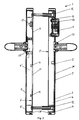
- Fig. 1 shows an exploded view of the invention Safety fitting and Fig. 2 is a sectional view of the inventive safety fitting.
- the base plate 3 has a right angle from her Contour recessed circumferential bar 6 on. This creates a box - like cage 3 ', with its open side on the Outside of the door leaf is arranged.
- the base plate 3 has in addition to a cylinder punched 7 a punched 8 for unhindered communication between an antenna 9 and a associated key or receiver. Behind the punching 8 is within the cage 3 'a mounting plate 10 for the attachment of Antenna 9 is provided.
- the outer shield 2 has a cylinder punching 7 "and a punching 8".
- the Punch 8 is closed with a cover 13 made of plastic, around the antenna 9 located behind it against mechanical damage, Sabotage or theft. Furthermore, the cover 13 with bolted to the mounting plate 10. The gland will be the Exterior shield 2 and the cage 3 'held together.
- the base plate 3 approximately identical counter-screw 4 also has on its contour via a circumferential web 6 '.
- a circumferential web 6 ' forms the Gegenschraubplatte 4 with the web 6 'a trough 4', the However, with the Schwarzschraubplatte 4 directly on the inside of the Door leaf rests. The opening of the tub 4 'points away from the door leaf.
- the web 6 ' has on the longitudinal sides of the tub 4' just above the Schmidtschraubplatte 4 flat rectangular punched 14 on, where always two punched 14 in opposite webs 6 'of Longitudinal side of the Gegenschraubplatte 4 directly opposite. to Fixation of assemblies such as a board 16 or a Battery 17 are between each two opposite each other Punches 14 suspensions 15 used.
- a suspension 15 consists of a base body 26 and two of the Base 26 outgoing, opposite elastic Arms 27.
- the elastic arms 27 are made of a bendable Made of plastic and pass through the punched holes 14 in the web 6 '.
- the board 16 can be screwed or glued to the suspension 15 become.
- Cheap areas for arranging assemblies are within the tub 4 'above a D Wegennesstanzung 18', between the Pusher punching 18 'and the Zylinderausstanzung 7' and below the Cylinder punching 7 '.
- the arranged on the Jacobschraubplatte 4 assemblies are together with the Gegenschraubplatte 4 with an inner shield. 5 covered.
- an inner shield 5 is used, the wider when the tub 4 ', the width of the suspension 15 by the length the arms 27 to the inner clear width of the inner shield 5 between two Grooves 20 adapted.
- the suspension 15 is in two parts executed as an excessive bending of the suspension 15 necessary would be to the two arms 27 at the same time in the associated Insert punching 14.
- the suspension 15 would at one to break strong bend.
- the suspension 15 fulfills a dual function: on the one hand it serves as Subrack in the tub 4 'and on the other hand as a spring clip for Snapping the inner shield 5.
- the Mounting plate 10 has a bore 24 and in the Gegenschraubplatte 4 a Bore 24 'and another hole in the door leaf for the Cable connection between the board 16 and the antennas 9 is provided.
- the outer shield 2 with the cage 3 'in the region of lower narrow side with a screw 28 positively connected to to prevent the outer shield 2 from unauthorized persons can be deducted.
- the screw 28 penetrates the outer shield second and the web 6 of the cage 3 '.
- Analog screw 28 are also conceivable in the inner plate 5, to counteract the theft of the battery 17. Since on the Inside the inner plate 5 and the Schwarzschraubplatte 4 not one Cover 13 and a base plate 3 are held together (because on the inside no antenna 9 is provided), is also in the Area of the upper narrow side in addition to the suspensions 15 a Screw 28 cheap.
- the cage 3 ' is used to a coupling unit 22 on the Stow the door leaf outside. From the coupling unit 22 protrude two Square pins 23, 23 '. The projecting towards the inside of the door leaf Square pin 23 'reaches through the door panel Einstemmunter and by the Gegenschraubplatte 4 and the Inner plate 5. Following the inner plate 5 is on the square pin 23 'an unrepresented internal handle mounted.
- bearing shells 25, 25 ' are provided for stabilized mounting of the two square pins 23, 23 'are respectively in Cage 3 'and in the tub 4' bearing shells 25, 25 'is provided.
- the bearing shell 25 is inserted into the cage 3 ', wherein the shaft on the outer shield 2 facing side of the Base plate 3 protrudes.
- the bearing shell 25 ' is from the open side in the Well 4 'used, the shaft points towards the inner plate 5.
- the cage 3 'and the tub 4' are very similar, the same Tools and the same tool sequence can be used.
- By the inventive design of cage 3 'and trough 4' thus arises a considerable saving potential with regard to the Production costs.
Landscapes
- Casings For Electric Apparatus (AREA)
- Shielding Devices Or Components To Electric Or Magnetic Fields (AREA)
- Elevator Door Apparatuses (AREA)
- Support Of Aerials (AREA)
- Lock And Its Accessories (AREA)
Abstract
Description
Claims (13)
- Beschlag (1) mit einem Außenschild (2) mit Zylinderausstanzung (7"), einer Unterlagsplatte (3), einer Gegenschraubplatte (4) und einem Innenschild (5) mit Zylinderaustanzung für ein Türblatt, dadurch gekennzeichnet, dass die Unterlags- (3) und Gegenschraubplatte (4) jeweils einen rundumlaufenden Steg (6, 6') aufweisen, wobei jeweils die Unterlags- (3) und die Gegenschraubplatte (4) mit dem zugehörigen rundumlaufenden Steg (6, 6') einen Käfig (3') bzw. eine Wanne (4') zur Unterbringung von Mechanik- und/oder Elektronikbaugruppen ausbilden, und dass der Käfig (3') und die Wanne (4') annähernd baugleich sind.
- Beschlag nach Anspruch 1, dadurch gekennzeichnet, dass die Unterlagsplatte (3) zusätzlich zur Zylinderausstanzung (7) eine Ausstanzung (8) zur ungehinderten Kommunikation zwischen einer Antenne (9), einer Empfangs- bzw. Auswerteelektronik einerseits und einem zugehörigen Schlüssel andererseits aufweist.
- Beschlag nach Anspruch 2, dadurch gekennzeichnet, dass im Bereich der Ausstanzung (8) zum Einbau einer Empfangs- bzw. Auswerteelektronik eine Montageplatte (10) mit einer Empfangs- bzw. Auswerteelektronik angeordnet ist.
- Beschlag nach einem der Ansprüche 1 bis 3, dadurch gekennzeichnet, dass im Bereich der Zylinderausstanzung (7) im Käfig (3') eine gehärtete Aufbohrschutzplatte (19) verschiebbar angeordnet ist, wobei die Aufbohrschutzplatte (19) über eine Ausstanzung verfügt, die exakt der äußeren Kontur des Schließzylinders entspricht.
- Beschlag nach einem der Ansprüche 1 bis 4, dadurch gekennzeichnet, dass der Steg (6') der Gegenschraubplatte (4) zum Fixieren von Baugruppen Ausstanzungen (14) aufweist.
- Beschlag nach Anspruch 5, dadurch gekennzeichnet, dass zwischen zwei gegenüberliegenden Ausstanzungen (14) zum Fixieren von Baugruppen eine Aufhängung (15) eingesetzt ist.
- Beschlag nach Anspruch 6, dadurch gekennzeichnet, dass die Aufhängung (15) einen Grundkörper (26) und zwei einander gegenüberliegende auskragende elastische Arme (27) aufweist.
- Beschlag nach Anspruch 6, dadurch gekennzeichnet, dass die Aufhängung (15) aus zwei Grundkörpern (26) mit jeweils einem Arm (27) besteht.
- Beschlag nach Anspruch 7 oder 8, dadurch gekennzeichnet, dass die Aufhängung (15) zur Befestigung des Innenschildes (5) an der Wanne (4') mit ihren Armen (27) zwei einander gegenüberliegende Ausstanzungen (14) durchgreift und die Arme (27) in Nuten (20) bzw. hinter Rippen auf der Innenseite des Innenschildes (5) einrasten.
- Beschlag nach einem der Ansprüche 1 bis 9, dadurch gekennzeichnet, dass das Außenschild (2) zusätzlich zu einer Zylinderausstanzung (7") eine Ausstanzung (8") zur ungehinderten Kommunikation zwischen einer Antenne (9), einer Empfangs- bzw. Auswerteelektronik einerseits und einem zugehörigen Schlüssel anderseits aufweist.
- Beschlag nach einem der Ansprüche 1 bis 10, dadurch gekennzeichnet, dass das Außenschild (2) mit dem Steg (6) des Käfigs (3') und/oder das Innenschild (5) mit dem Steg (6') der Wanne (4') mit einer Schraube (28) an zumindest der der Zylinderausstanzung (7, 7', 7") benachbarten Schmalseite des Beschlages (1) verschraubt ist.
- Beschlag nach einem der Ansprüche 1 bis 11, dadurch gekennzeichnet, dass die Montageplatte (10) und die Abdeckung (13) zur Befestigung des Außenschildes (2) an dem Käfig (3') miteinander verschraubt sind.
- Beschlag nach einem der Ansprüche 1 bis 12, dadurch gekennzeichnet, dass das Außenschild (2) und das Innenschild (5) annähernd baugleich sind.
Applications Claiming Priority (2)
| Application Number | Priority Date | Filing Date | Title |
|---|---|---|---|
| AT0008904U AT7368U1 (de) | 2004-02-06 | 2004-02-06 | Beschlag |
| AT892004U | 2004-02-06 |
Publications (3)
| Publication Number | Publication Date |
|---|---|
| EP1580354A2 true EP1580354A2 (de) | 2005-09-28 |
| EP1580354A3 EP1580354A3 (de) | 2009-10-21 |
| EP1580354B1 EP1580354B1 (de) | 2011-08-24 |
Family
ID=33494458
Family Applications (1)
| Application Number | Title | Priority Date | Filing Date |
|---|---|---|---|
| EP05100767A Expired - Lifetime EP1580354B1 (de) | 2004-02-06 | 2005-02-04 | Beschlag |
Country Status (2)
| Country | Link |
|---|---|
| EP (1) | EP1580354B1 (de) |
| AT (2) | AT7368U1 (de) |
Cited By (4)
| Publication number | Priority date | Publication date | Assignee | Title |
|---|---|---|---|---|
| EP2998469A1 (de) * | 2014-09-22 | 2016-03-23 | DORMA Deutschland GmbH | Beschlagskörper für einen Beschlag für eine Gebäudetür |
| EP2998484A1 (de) * | 2014-09-22 | 2016-03-23 | DORMA Deutschland GmbH | Beschlag für eine Gebäudetür |
| CN108343313A (zh) * | 2018-01-22 | 2018-07-31 | 苏州地威智能科技有限公司 | 一种可采用同一模具加工设计的智能电子门锁的前壳和后壳 |
| EP2909402B1 (de) | 2012-10-17 | 2018-12-19 | dormakaba Deutschland GmbH | System zur betätigung eines schlosses |
Families Citing this family (3)
| Publication number | Priority date | Publication date | Assignee | Title |
|---|---|---|---|---|
| AT516346A1 (de) * | 2014-09-15 | 2016-04-15 | Makivic Michael | Türschild für einen Türbeschlag |
| EP2998470B1 (de) * | 2014-09-22 | 2018-12-19 | dormakaba Deutschland GmbH | Beschlag für eine gebäudetür |
| EP2998468B1 (de) | 2014-09-22 | 2018-12-26 | dormakaba Deutschland GmbH | Beschlagskörper für einen Beschlag und Verfahren |
Family Cites Families (2)
| Publication number | Priority date | Publication date | Assignee | Title |
|---|---|---|---|---|
| DE29804903U1 (de) * | 1998-03-18 | 1999-07-22 | Niemann, Hans Dieter, 50169 Kerpen | Sicherheitsrosette an einem Schließzylinder |
| US20020095962A1 (en) * | 2001-01-19 | 2002-07-25 | Alan Doerr | Thumbturn extension assembly |
-
2004
- 2004-02-06 AT AT0008904U patent/AT7368U1/de not_active IP Right Cessation
-
2005
- 2005-02-04 EP EP05100767A patent/EP1580354B1/de not_active Expired - Lifetime
- 2005-02-04 AT AT05100767T patent/ATE521769T1/de active
Non-Patent Citations (1)
| Title |
|---|
| None |
Cited By (5)
| Publication number | Priority date | Publication date | Assignee | Title |
|---|---|---|---|---|
| EP2909402B1 (de) | 2012-10-17 | 2018-12-19 | dormakaba Deutschland GmbH | System zur betätigung eines schlosses |
| EP2909402B2 (de) † | 2012-10-17 | 2021-12-15 | dormakaba Deutschland GmbH | System zur betätigung eines schlosses |
| EP2998469A1 (de) * | 2014-09-22 | 2016-03-23 | DORMA Deutschland GmbH | Beschlagskörper für einen Beschlag für eine Gebäudetür |
| EP2998484A1 (de) * | 2014-09-22 | 2016-03-23 | DORMA Deutschland GmbH | Beschlag für eine Gebäudetür |
| CN108343313A (zh) * | 2018-01-22 | 2018-07-31 | 苏州地威智能科技有限公司 | 一种可采用同一模具加工设计的智能电子门锁的前壳和后壳 |
Also Published As
| Publication number | Publication date |
|---|---|
| HK1086052A1 (zh) | 2006-09-08 |
| EP1580354A3 (de) | 2009-10-21 |
| ATE521769T1 (de) | 2011-09-15 |
| EP1580354B1 (de) | 2011-08-24 |
| AT7368U1 (de) | 2005-02-25 |
Similar Documents
| Publication | Publication Date | Title |
|---|---|---|
| DE102012112520B4 (de) | Türaußengriffsystem bei einem Kraftfahrzeug | |
| EP2518245B1 (de) | Handhabe mit einem Sicherungselement, dessen Befestigungsmittel vollständig innenseitig eines beweglichen Teils verbleibt | |
| DE102018202563B4 (de) | Knauf für einen elektronischen Schließzylinder | |
| EP1256671B1 (de) | Rosette für einen zugeordneten Schliesszylinder | |
| EP2042671B1 (de) | Vorrichtung zur sicheren Anbringung eines Griff-Betätigungsstiftes an einer Befestigungöffnung eines Griffs | |
| DE102015111940A1 (de) | Drehknauf zum Betätigen eines Zylinderadapters eines Schließzylinders | |
| EP2998485B1 (de) | Drehknauf zum betätigen eines zylinderadapters eines schliesszylinders | |
| DE29607944U1 (de) | Elektronisches Türschloß | |
| EP1580354B1 (de) | Beschlag | |
| EP2692968B1 (de) | Knaufzylinder | |
| DE102005059383B4 (de) | System zum Ausgleich von Längendifferenzen zwischen einem in eine Öffnung eines Türblattes einzusetzenden Zylinderschloss und dem Türblatt | |
| DE102007011554B4 (de) | Koppeleinheit für elektronische Schließ-Systeme | |
| EP1922459B1 (de) | Schliesszylinder für in einem Fahrzeug vollziehbare Funktionen | |
| DE102005036435B4 (de) | Bewegungsmelder mit Montagesockel-Unterteil und Montagesockel-Abdeckung | |
| EP3187671B1 (de) | Verriegelungsvorrichtung als einbruchssicherung für z. b. fenster und türen | |
| EP2037062B1 (de) | Schnappschloss | |
| EP1152106B1 (de) | Betätigungshandhabe | |
| DE202009000484U1 (de) | Riegelverschlussvorrichtung für eine Kraftfahrzeugtür | |
| DE102015111937A1 (de) | Drehknauf zum Betätigen eines Zylinderadapters eines Schließzylinders | |
| EP3884131B1 (de) | Schliesssystem für eine tür oder klappe eines kraftfahrzeugs, tür oder klappe eines kraftfahrzeugs, kraftfahrzeug | |
| EP2998486A1 (de) | Drehknauf zum betätigen eines zylinderadapters eines schliesszylinders | |
| EP3514302B1 (de) | Türbeschlag und verfahren zum montieren eines türbeschlags | |
| EP0585735A1 (de) | Schlosssicherung für Sicherheitsschliess-Zylinder | |
| EP3974604B1 (de) | Türbeschlag, insbesondere für eine rohrrahmentür | |
| EP2331778B1 (de) | Notentriegelung für schlösser mit profilhalbzylinder |
Legal Events
| Date | Code | Title | Description |
|---|---|---|---|
| PUAI | Public reference made under article 153(3) epc to a published international application that has entered the european phase |
Free format text: ORIGINAL CODE: 0009012 |
|
| AK | Designated contracting states |
Kind code of ref document: A2 Designated state(s): AT BE BG CH CY CZ DE DK EE ES FI FR GB GR HU IE IS IT LI LT LU MC NL PL PT RO SE SI SK TR |
|
| AX | Request for extension of the european patent |
Extension state: AL BA HR LV MK YU |
|
| REG | Reference to a national code |
Ref country code: HK Ref legal event code: DE Ref document number: 1086052 Country of ref document: HK |
|
| RAP1 | Party data changed (applicant data changed or rights of an application transferred) |
Owner name: KABA GMBH |
|
| PUAL | Search report despatched |
Free format text: ORIGINAL CODE: 0009013 |
|
| AK | Designated contracting states |
Kind code of ref document: A3 Designated state(s): AT BE BG CH CY CZ DE DK EE ES FI FR GB GR HU IE IS IT LI LT LU MC NL PL PT RO SE SI SK TR |
|
| AX | Request for extension of the european patent |
Extension state: AL BA HR LV MK YU |
|
| RIC1 | Information provided on ipc code assigned before grant |
Ipc: E05B 47/06 20060101ALI20090914BHEP Ipc: E05B 9/00 20060101AFI20050805BHEP Ipc: E05B 15/02 20060101ALI20090914BHEP |
|
| 17P | Request for examination filed |
Effective date: 20100324 |
|
| AKX | Designation fees paid |
Designated state(s): AT CH DE FR GB LI |
|
| GRAP | Despatch of communication of intention to grant a patent |
Free format text: ORIGINAL CODE: EPIDOSNIGR1 |
|
| GRAS | Grant fee paid |
Free format text: ORIGINAL CODE: EPIDOSNIGR3 |
|
| GRAA | (expected) grant |
Free format text: ORIGINAL CODE: 0009210 |
|
| AK | Designated contracting states |
Kind code of ref document: B1 Designated state(s): AT CH DE FR GB LI |
|
| REG | Reference to a national code |
Ref country code: GB Ref legal event code: FG4D Free format text: NOT ENGLISH |
|
| REG | Reference to a national code |
Ref country code: CH Ref legal event code: EP |
|
| REG | Reference to a national code |
Ref country code: DE Ref legal event code: R096 Ref document number: 502005011801 Country of ref document: DE Effective date: 20111020 |
|
| REG | Reference to a national code |
Ref country code: CH Ref legal event code: NV Representative=s name: SCHNEIDER FELDMANN AG PATENT- UND MARKENANWAELTE |
|
| REG | Reference to a national code |
Ref country code: HK Ref legal event code: GR Ref document number: 1086052 Country of ref document: HK |
|
| PGFP | Annual fee paid to national office [announced via postgrant information from national office to epo] |
Ref country code: GB Payment date: 20120222 Year of fee payment: 8 |
|
| PLBE | No opposition filed within time limit |
Free format text: ORIGINAL CODE: 0009261 |
|
| STAA | Information on the status of an ep patent application or granted ep patent |
Free format text: STATUS: NO OPPOSITION FILED WITHIN TIME LIMIT |
|
| 26N | No opposition filed |
Effective date: 20120525 |
|
| REG | Reference to a national code |
Ref country code: DE Ref legal event code: R097 Ref document number: 502005011801 Country of ref document: DE Effective date: 20120525 |
|
| REG | Reference to a national code |
Ref country code: FR Ref legal event code: ST Effective date: 20121031 |
|
| PG25 | Lapsed in a contracting state [announced via postgrant information from national office to epo] |
Ref country code: FR Free format text: LAPSE BECAUSE OF NON-PAYMENT OF DUE FEES Effective date: 20120229 |
|
| PGFP | Annual fee paid to national office [announced via postgrant information from national office to epo] |
Ref country code: AT Payment date: 20130228 Year of fee payment: 9 |
|
| PGFP | Annual fee paid to national office [announced via postgrant information from national office to epo] |
Ref country code: CH Payment date: 20130527 Year of fee payment: 9 |
|
| GBPC | Gb: european patent ceased through non-payment of renewal fee |
Effective date: 20130204 |
|
| PG25 | Lapsed in a contracting state [announced via postgrant information from national office to epo] |
Ref country code: GB Free format text: LAPSE BECAUSE OF NON-PAYMENT OF DUE FEES Effective date: 20130204 |
|
| REG | Reference to a national code |
Ref country code: CH Ref legal event code: PL |
|
| REG | Reference to a national code |
Ref country code: AT Ref legal event code: MM01 Ref document number: 521769 Country of ref document: AT Kind code of ref document: T Effective date: 20140204 |
|
| PG25 | Lapsed in a contracting state [announced via postgrant information from national office to epo] |
Ref country code: CH Free format text: LAPSE BECAUSE OF NON-PAYMENT OF DUE FEES Effective date: 20140228 Ref country code: LI Free format text: LAPSE BECAUSE OF NON-PAYMENT OF DUE FEES Effective date: 20140228 |
|
| PG25 | Lapsed in a contracting state [announced via postgrant information from national office to epo] |
Ref country code: AT Free format text: LAPSE BECAUSE OF NON-PAYMENT OF DUE FEES Effective date: 20140204 |
|
| PGFP | Annual fee paid to national office [announced via postgrant information from national office to epo] |
Ref country code: DE Payment date: 20160229 Year of fee payment: 12 |
|
| REG | Reference to a national code |
Ref country code: DE Ref legal event code: R119 Ref document number: 502005011801 Country of ref document: DE |
|
| PG25 | Lapsed in a contracting state [announced via postgrant information from national office to epo] |
Ref country code: DE Free format text: LAPSE BECAUSE OF NON-PAYMENT OF DUE FEES Effective date: 20170901 |