EP2503315A2 - Mikrotom mit Oberflächenorientierungssensor zur Erfassung der Orientierung der Oberfläche von Proben - Google Patents
Mikrotom mit Oberflächenorientierungssensor zur Erfassung der Orientierung der Oberfläche von Proben Download PDFInfo
- Publication number
- EP2503315A2 EP2503315A2 EP20120159609 EP12159609A EP2503315A2 EP 2503315 A2 EP2503315 A2 EP 2503315A2 EP 20120159609 EP20120159609 EP 20120159609 EP 12159609 A EP12159609 A EP 12159609A EP 2503315 A2 EP2503315 A2 EP 2503315A2
- Authority
- EP
- European Patent Office
- Prior art keywords
- sample
- sectioning device
- sectioning
- orientation
- sensing
- Prior art date
- Legal status (The legal status is an assumption and is not a legal conclusion. Google has not performed a legal analysis and makes no representation as to the accuracy of the status listed.)
- Granted
Links
- 238000005520 cutting process Methods 0.000 claims abstract description 122
- 230000007246 mechanism Effects 0.000 claims abstract description 47
- 238000000034 method Methods 0.000 claims description 20
- 239000000463 material Substances 0.000 description 21
- 241000078511 Microtome Species 0.000 description 11
- 238000005259 measurement Methods 0.000 description 10
- 230000003287 optical effect Effects 0.000 description 9
- 230000008878 coupling Effects 0.000 description 6
- 238000010168 coupling process Methods 0.000 description 6
- 238000005859 coupling reaction Methods 0.000 description 6
- 238000003825 pressing Methods 0.000 description 6
- 239000001993 wax Substances 0.000 description 6
- 239000003795 chemical substances by application Substances 0.000 description 5
- 239000012188 paraffin wax Substances 0.000 description 5
- WSFSSNUMVMOOMR-UHFFFAOYSA-N Formaldehyde Chemical compound O=C WSFSSNUMVMOOMR-UHFFFAOYSA-N 0.000 description 4
- 229920002866 paraformaldehyde Polymers 0.000 description 4
- 230000008569 process Effects 0.000 description 4
- 229910052782 aluminium Inorganic materials 0.000 description 3
- XAGFODPZIPBFFR-UHFFFAOYSA-N aluminium Chemical compound [Al] XAGFODPZIPBFFR-UHFFFAOYSA-N 0.000 description 3
- 238000000429 assembly Methods 0.000 description 3
- 230000000712 assembly Effects 0.000 description 3
- 238000006073 displacement reaction Methods 0.000 description 3
- 229910052751 metal Inorganic materials 0.000 description 3
- 239000002184 metal Substances 0.000 description 3
- 238000012986 modification Methods 0.000 description 3
- 230000004048 modification Effects 0.000 description 3
- 239000004033 plastic Substances 0.000 description 3
- 229920003023 plastic Polymers 0.000 description 3
- 238000003860 storage Methods 0.000 description 3
- 238000004458 analytical method Methods 0.000 description 2
- 230000008901 benefit Effects 0.000 description 2
- 238000001574 biopsy Methods 0.000 description 2
- 230000005389 magnetism Effects 0.000 description 2
- 150000002739 metals Chemical class 0.000 description 2
- 239000000203 mixture Substances 0.000 description 2
- 229920001343 polytetrafluoroethylene Polymers 0.000 description 2
- 239000004810 polytetrafluoroethylene Substances 0.000 description 2
- 239000011253 protective coating Substances 0.000 description 2
- 229910001220 stainless steel Inorganic materials 0.000 description 2
- 239000010935 stainless steel Substances 0.000 description 2
- XLYOFNOQVPJJNP-UHFFFAOYSA-N water Substances O XLYOFNOQVPJJNP-UHFFFAOYSA-N 0.000 description 2
- 230000006978 adaptation Effects 0.000 description 1
- 238000013459 approach Methods 0.000 description 1
- 208000003295 carpal tunnel syndrome Diseases 0.000 description 1
- 230000001413 cellular effect Effects 0.000 description 1
- 230000008859 change Effects 0.000 description 1
- 239000011248 coating agent Substances 0.000 description 1
- 238000000576 coating method Methods 0.000 description 1
- 238000004891 communication Methods 0.000 description 1
- 238000004590 computer program Methods 0.000 description 1
- 230000003247 decreasing effect Effects 0.000 description 1
- 238000010586 diagram Methods 0.000 description 1
- 238000001035 drying Methods 0.000 description 1
- 230000006870 function Effects 0.000 description 1
- 238000001764 infiltration Methods 0.000 description 1
- 230000008595 infiltration Effects 0.000 description 1
- 230000000977 initiatory effect Effects 0.000 description 1
- 230000003993 interaction Effects 0.000 description 1
- 238000005305 interferometry Methods 0.000 description 1
- 239000000696 magnetic material Substances 0.000 description 1
- 238000004519 manufacturing process Methods 0.000 description 1
- 239000012782 phase change material Substances 0.000 description 1
- 239000004014 plasticizer Substances 0.000 description 1
- 229920000642 polymer Polymers 0.000 description 1
- -1 polytetrafluoroethylene Polymers 0.000 description 1
- 238000012545 processing Methods 0.000 description 1
- 239000004065 semiconductor Substances 0.000 description 1
- 230000011664 signaling Effects 0.000 description 1
- 239000007787 solid Substances 0.000 description 1
- 239000000126 substance Substances 0.000 description 1
Images


Classifications
-
- G—PHYSICS
- G01—MEASURING; TESTING
- G01N—INVESTIGATING OR ANALYSING MATERIALS BY DETERMINING THEIR CHEMICAL OR PHYSICAL PROPERTIES
- G01N1/00—Sampling; Preparing specimens for investigation
- G01N1/02—Devices for withdrawing samples
- G01N1/04—Devices for withdrawing samples in the solid state, e.g. by cutting
- G01N1/06—Devices for withdrawing samples in the solid state, e.g. by cutting providing a thin slice, e.g. microtome
-
- Y—GENERAL TAGGING OF NEW TECHNOLOGICAL DEVELOPMENTS; GENERAL TAGGING OF CROSS-SECTIONAL TECHNOLOGIES SPANNING OVER SEVERAL SECTIONS OF THE IPC; TECHNICAL SUBJECTS COVERED BY FORMER USPC CROSS-REFERENCE ART COLLECTIONS [XRACs] AND DIGESTS
- Y10—TECHNICAL SUBJECTS COVERED BY FORMER USPC
- Y10S—TECHNICAL SUBJECTS COVERED BY FORMER USPC CROSS-REFERENCE ART COLLECTIONS [XRACs] AND DIGESTS
- Y10S83/00—Cutting
- Y10S83/9155—Microtome
-
- Y—GENERAL TAGGING OF NEW TECHNOLOGICAL DEVELOPMENTS; GENERAL TAGGING OF CROSS-SECTIONAL TECHNOLOGIES SPANNING OVER SEVERAL SECTIONS OF THE IPC; TECHNICAL SUBJECTS COVERED BY FORMER USPC CROSS-REFERENCE ART COLLECTIONS [XRACs] AND DIGESTS
- Y10—TECHNICAL SUBJECTS COVERED BY FORMER USPC
- Y10T—TECHNICAL SUBJECTS COVERED BY FORMER US CLASSIFICATION
- Y10T83/00—Cutting
- Y10T83/04—Processes
-
- Y—GENERAL TAGGING OF NEW TECHNOLOGICAL DEVELOPMENTS; GENERAL TAGGING OF CROSS-SECTIONAL TECHNOLOGIES SPANNING OVER SEVERAL SECTIONS OF THE IPC; TECHNICAL SUBJECTS COVERED BY FORMER USPC CROSS-REFERENCE ART COLLECTIONS [XRACs] AND DIGESTS
- Y10—TECHNICAL SUBJECTS COVERED BY FORMER USPC
- Y10T—TECHNICAL SUBJECTS COVERED BY FORMER US CLASSIFICATION
- Y10T83/00—Cutting
- Y10T83/141—With means to monitor and control operation [e.g., self-regulating means]
-
- Y—GENERAL TAGGING OF NEW TECHNOLOGICAL DEVELOPMENTS; GENERAL TAGGING OF CROSS-SECTIONAL TECHNOLOGIES SPANNING OVER SEVERAL SECTIONS OF THE IPC; TECHNICAL SUBJECTS COVERED BY FORMER USPC CROSS-REFERENCE ART COLLECTIONS [XRACs] AND DIGESTS
- Y10—TECHNICAL SUBJECTS COVERED BY FORMER USPC
- Y10T—TECHNICAL SUBJECTS COVERED BY FORMER US CLASSIFICATION
- Y10T83/00—Cutting
- Y10T83/525—Operation controlled by detector means responsive to work
- Y10T83/536—Movement of work controlled
-
- Y—GENERAL TAGGING OF NEW TECHNOLOGICAL DEVELOPMENTS; GENERAL TAGGING OF CROSS-SECTIONAL TECHNOLOGIES SPANNING OVER SEVERAL SECTIONS OF THE IPC; TECHNICAL SUBJECTS COVERED BY FORMER USPC CROSS-REFERENCE ART COLLECTIONS [XRACs] AND DIGESTS
- Y10—TECHNICAL SUBJECTS COVERED BY FORMER USPC
- Y10T—TECHNICAL SUBJECTS COVERED BY FORMER US CLASSIFICATION
- Y10T83/00—Cutting
- Y10T83/525—Operation controlled by detector means responsive to work
- Y10T83/538—Positioning of tool controlled
-
- Y—GENERAL TAGGING OF NEW TECHNOLOGICAL DEVELOPMENTS; GENERAL TAGGING OF CROSS-SECTIONAL TECHNOLOGIES SPANNING OVER SEVERAL SECTIONS OF THE IPC; TECHNICAL SUBJECTS COVERED BY FORMER USPC CROSS-REFERENCE ART COLLECTIONS [XRACs] AND DIGESTS
- Y10—TECHNICAL SUBJECTS COVERED BY FORMER USPC
- Y10T—TECHNICAL SUBJECTS COVERED BY FORMER US CLASSIFICATION
- Y10T83/00—Cutting
- Y10T83/647—With means to convey work relative to tool station
- Y10T83/6572—With additional mans to engage work and orient it relative to tool station
Definitions
- Embodiments of the invention relate to microtomes or other tissue sample sectioning devices to produce sections of samples, specifically some embodiments relate to microtomes or other tissue sample sectioning devices that have surface orientation sensors to sense orientations of surfaces of the samples.
- Histology is a science or discipline associated with the processing of tissue for examination or analysis.
- the examination or analysis may be of the cellular morphology, chemical composition, tissue structure or composition, or other tissue characteristics.
- a sample of tissue may be prepared for sectioning by a microtome or other sample sectioning device.
- the tissue may be dried or dehydrated by removing most or almost all of the water from the tissue, for example by exposing the tissue to one or more dehydrating agents. After drying the tissue, clearing of the dehydrating agents may optionally be performed, and then an embedding agent (e.g., wax with added plasticizers) may be introduced or infiltrated into the dried tissue. The removal of the water and the infiltration of the embedding agent may aid in sectioning the tissue into thin sections with the microtome.
- an embedding agent e.g., wax with added plasticizers
- Embedding may then be performed on the tissue.
- the tissue that has been dried and infiltrated with the embedding agent may be embedded in a block or other mass of wax, various polymers, or another embedding medium.
- the dried and wax-infiltrated tissue may be placed in a mold and/or cassette, melted wax may be dispensed over the tissue until the mold has been filled with the wax, and then the wax may be cooled and hardened. Embedding the tissue in the block of wax may help to provide additional support during cutting or sectioning of the tissue with a microtome.
- the microtome may be used to cut thin slices or sections of the sample of tissue.
- Various different types of microtomes are known in the arts. Representative types include, for example, sled, rotary, vibrating, saw, and laser microtomes.
- the microtomes may be manual or automated. Automated microtomes may include motorized systems or drive systems to drive or automate a cutting movement between the sample from which the sections are to be cut and a cutting mechanism used to cut the sections. It is to be appreciated that microtomes may also be used for other purposes besides just histology, and that microtomes may be used on other types of samples besides just embedded tissue.
- FIG. 1 illustrates a schematic view of an embodiment of a microtome or other sample sectioning device.
- Microtome 100 may include base member 101 having feed drive system or cutting drive system 102, mounting member 103 and handwheel 104 attached thereto.
- Feed drive system 102 may be supported above base member 101 by support member 115.
- Feed drive system 102 may include vertical drive member 105, horizontal drive member 106 and sample holder 107 operable to hold sample 108.
- Sample 108 may include a piece of tissue that is to be sectioned, for example, a piece of tissue embedded in paraffin.
- the cutting drive system or feed drive system is operable to drive movement of the sample held by the sample holder.
- Motor 109 of feed drive system 102 may be mechanically coupled to vertical drive member 105 and operable to drive vertical movement of vertical drive member 105 in a direction of vertical double arrow 126.
- Motor 110 of feed drive system 102 may be mechanically coupled to horizontal drive member 106 to drive horizontal movement of horizontal drive member 106 in a direction of horizontal double arrow 125.
- terms such as “horizontal”, “vertical”, “top”, “bottom”, “upper”, “lower”, and the like, are used herein to facilitate the description of the illustrated device. It is possible for other devices to replace horizontal movements with vertical movements, etc.
- Mounting member 103 may include mounting base 111 which provides a mounting surface for cutting member or mechanism 112.
- Cutting member or mechanism 112 may be, for example, a blade or knife of various types of materials mounted to mounting member 103, or other types of cutting mechanisms suitable for microtomes.
- Section receiving member 113 may be positioned along one side of cutting member 112.
- Section receiving member 113 is dimensioned to receive a section cut from sample 108 by cutting member or blade 112.
- section receiving member 113 may have an inclined surface extending from a cutting edge of blade 112 to the surface of mounting member 103. As cutting member or blade 112 slices through sample 108, the section cut from sample 108 is separated from sample 108 and extends along section receiving member 113.
- microtome 100 may include a surface orientation sensor assembly 114.
- Surface orientation sensor assembly 114 is operable to sense or measure an orientation or angle of a surface of sample 108.
- the orientation or angle of the surface of sample 108 may be sensed or determined in various different ways.
- the surface of sample 108 may contact sensor assembly 114, and one or more movable portions of sensor assembly 114 may conform to an orientation of the surface of sample 108.
- the movement of the one or more movable portions of sensor assembly may allow microtome 100 to autonomously sense or determine the orientation of the surface of sample 108.
- Optical and other sensing mechanisms are also suitable.
- the sensed orientation may be used to adjust or align the surface of the sample 108 so that it is parallel, substantially parallel, or at least more parallel with cutting member or mechanism 112 and/or cutting plane 124 associated with cutting member or mechanism 112. It is advantageous that the surface of sample 108 be sufficiently aligned parallel with cutting member 112 and/or cutting plane 124 so that the sample sections cut by microtome 100 are sufficiently evenly cut.
- microtome 100 may optionally be capable of autonomously adjusting or aligning the orientation of surface of sample 108 parallel, sufficiently parallel, or at least more parallel, with cutting member 112 and/or cutting plane 124.
- Microtome 100 may have logic to autonomously sense and/or adjust an orientation of the surface of the sample relative to a cutting plane and/or cutting mechanism based on the sensed orientation.
- this may help to improve alignment accuracy and/or relieve an operator from performing the adjustment manually.
- the adjustment may be performed manually, if desired.
- An embodiment of a method of sectioning may include microtome 100 autonomously sensing an orientation of a surface of sample 108 using sensor assembly 114, an operator manually or microtome 100 autonomously adjusting the orientation of the surface of sample 108, and microtome 100 taking a section of sample 108 after such adjustment.
- sensor assembly 114 is movably coupled to mounting base 111 at a position between feed drive system 102 and mounting member 103, although this is not required.
- Mounting base 111 provides a support surface for sensor assembly 114 and is dimensioned and coupled to accommodate sliding of sensor assembly 114 vertically in a direction of vertical double arrow 126B.
- sensor assembly 114 is operable to slide along mounting base 111 in an upward vertical direction toward feed drive system 102, and vertical drive member 105 is operable to cause feed drive system 102 to move in a downward vertical direction toward sensor assembly 114.
- horizontal drive member 106 is operable to cause feed drive system 102 to move in a horizontal direction toward sensor assembly 114 in the direction of horizontal arrow 125 so that a surface of sample 108 is appropriately positioned relative to sensor assembly 114 to allow for surface orientation measurement.
- sensor assembly 114 is operable to retract in a vertical downward direction as viewed (e.g., to a retracted position away from the movement between the sample held by the sample holder and the cutting mechanism.)
- operation of feed drive system 102 may be controlled using handwheel 104 and/or control device 116.
- Handwheel 104 may include handle or other pulse generating device 117 to lock the handwheel 104. Rotation of handwheel 104 may be operable to cause vertical drive member 105 to move in a vertical direction shown by vertical double arrow 126 to facilitate slicing of sample 108.
- handwheel 104 may be a decoupled handwheel, which is not mechanically coupled to feed drive system 102. Rather, decoupled handwheel 104 may be electrically connected to an encoder (not shown) and control circuit 118 via control line 119. The rotation of decoupled handwheel 104 may cause the encoder to deliver an electrical signal to control circuit 118.
- Control circuit 118 is connected to motor 109 via control line 120 and is operable to control movement of vertical drive member 105 according to the electrical signal from the encoder. Control circuit 118 is also connected to motor 110 via control line 121 and is connected to sensor assembly 114 via control line 122.
- signals from control device 116 may be transmitted to control circuit 118 to control or facilitate operation of sensor assembly 114, handwheel 104, motor 109 and/or motor 110.
- control device 116 may be, for example, a keyboard, a capacitive sensor touch pad, or other user or data input device.
- signals are transmitted between control device 116 and control circuit 118 via control line 123.
- control device 116 is a wireless control device that is operable to wirelessly transmit signals to control circuit 118 and control line 123 is omitted.
- FIG. 2 illustrates an embodiment of a surface orientation sensor assembly.
- surface orientation sensor assembly 214 in FIG. 2 may optionally have similar characteristics to sensor assembly 114 in FIG. 1 .
- Surface orientation sensor assembly 214 is used to facilitate autonomous alignment of a surface of a sample with a cutting mechanism and/or cutting plane. It is advantageous that the surface of the sample be sufficiently aligned parallel to the cutting mechanism (e.g., a blade) so that sections are cut evenly. To align the sample, the sample contacts sensor assembly 214 and sensor assembly 214 detects an orientation of the surface of the sample.
- the surface of the sample will not be aligned parallel or sufficiently parallel with the cutting plane.
- Sensor assembly 214 detects the angle of the surface of the sample with respect to the cutting plane. Using the sensed information, the sample may be adjusted to an adjusted position where the surface of the sample is parallel, or at least more parallel, with the cutting plane.
- the illustrated embodiment of the sensor assembly 214 includes sensing plate 230 and sensing frame 231.
- Sensing frame 231 is positioned around sensing plate 230.
- Sensing plate 230 may be planar and/or have a flat surface (e.g., be a planar plate).
- a thickness of sensing plate may be on the order of several millimeters (e.g., 0.5mm to 5mm) depending on the material. Dimensions across sensing plate may be on the order of about 20-60mm.
- Sensing plate and sensing frame may be constructed of various materials, such as, for example, aluminum, stainless steel, other metals, rigid plastics, and combinations thereof optionally coated with protective coatings.
- sensing plate 230 and sensing frame 231 are substantially square with respect to a length and a width dimension with the sensing plate having truncated corners and the sensing frame having conforming frame corner portions, but in alternate embodiments they may be more or less square, or may be rectangular, circular, oval, octagonal, hexagonal, or otherwise.
- the sensing plate is square with dimensions of approximately 39.5mm x 39.5mm, is constructed of aluminum having a protective coating (e.g., a polytetrafluoroethylene (PTFE) coating), and the sensing frame is approximately 90mm x 75mm x 25mm thick and made of metal (e.g., aluminum) and/or plastic.
- PTFE polytetrafluoroethylene
- sensing plate 230 is a first sensing member that is rotatable about first axial support member 232
- sensing frame 231 is a second sensing member that is rotatable about second axial support member 233.
- First axial support member 232 diagonally bisects sensing plate 230.
- Second axial support member 233 diagonally bisects sensing frame 231.
- First axial support member 232 is substantially perpendicular to second axial support member 233 (for example 80-100 degrees).
- sensing plate 230 is rotatable along an axis orthogonal or perpendicular to the axis of rotation for sensing frame 231.
- Sensing plate 230 and sensing frame 231 are also movable in a horizontal direction when the sample is pressed against sensing plate 230.
- the movement in the horizontal direction may provide information about the horizontal position (i.e., into and out of the page as viewed) of the surface of sample.
- both an angular orientation of the surface of the sample, as well as a horizontal position of the surface of the sample with respect to the cutting plane can be detected by sensor assembly 214.
- Sensor assembly 214 further includes sensing plate sensor 234 and sensing plate signal output member 235.
- Sensing plate sensor 234 is attached to sensing assembly frame 238 while sensing plate signal output member 235 is attached to sensing plate 230.
- sensing plate signal output member 235 may be attached to sensing plate 230 at or proximate a corner or other portion most distant from an axis of rotation of the sensing plate 230.
- Sensing plate sensor 234 is sufficiently aligned with sensing plate signal output member 235 to receive a signal from sensing plate signal output member 235. The signal received is indicative of an amount of rotation or displacement of sensing plate 230.
- sensing plate sensor 234 may detect a position of sensing plate 230.
- sensing plate sensor 234 is operable to sense a magnetic field of magnet 235 (for example through a magneto-resistive sensing mechanism) to detect a position of sensing plate 230.
- magnetism instead of using magnetism, other sensing mechanisms may be used, such as, for example, mechanical sensors (for example a strain gauge), electrical sensors (for example using capacitance), optical sensors, or other sensors may optionally be used.
- Sensor assembly 214 also includes sensing frame sensor 236 and sensing frame signal output member 237.
- Sensing frame sensor 236 is attached to sensing assembly frame 238 while sensing frame signal output member 237 is attached to sensing frame 231.
- sensing frame signal output member 237 may be attached to sensing frame 231 at or proximate a corner or other portion most distant from the axis of rotation of the sensing frame 231.
- Sensing frame sensor 236 is sufficiently aligned with sensing frame signal output member 237 so that it can receive a signal from sensing frame signal output member 237.
- sensing frame signal output member 237 may include a magnet and sensing frame sensor 236 may detect a magnetic field or signal from sensing frame signal output member 237 to detect an angle of rotation ( ⁇ ) of sensing frame 231, which typically is on the order of several degrees (e.g., 0 to 10°).
- ⁇ angle of rotation
- second axial support member 233 of sensing frame 231 is substantially orthogonal to first axial support member 232 of sensing plate 230. Accordingly, the angle of the surface of the sample with respect to the cutting plane with respect to second axial support member 233 can further be detected by sensing frame sensor 236.
- a signal may be provided from the sensor assembly 214 to a control component of microtome 100 (e.g., control circuit 118 and/or control device 116).
- the signal may represent the degree or extent that the cutting surface is offset from the cutting plane as determined from the rotation of sensing plate 230 and sensing fame 231.
- the control component may autonomously or under user direction cause the feed drive system to modify the orientation of the surface of the sample from an initial orientation to a changed orientation in which the cutting surface of the sample is more parallel with the cutting plane.
- calibration may be used to characterize a condition where sensing plate 230 and sensing frame 231 are aligned parallel with the cutting mechanism and/or the cutting plane.
- sensing plate 230 and sensing frame 231 may be moved, for example manually or by being forced by a mechanical calibration piece, so that they are aligned parallel with the cutting mechanism and/or the cutting plane.
- Outputs of sensing plate sensor 234 and sensing frame sensor 236 may be determined as calibration data in this condition.
- the calibration data may include magneto-resistive values or indications of strengths of magnetic fields experienced by the respective sensing plate sensor 234 and sensing frame sensor 236.
- This calibration data may be stored in a machine-readable medium (e.g., a memory), or otherwise preserved by the microtome.
- the calibration data may be accessed and used subsequently when adjusting the orientation of a surface of a sample.
- the microtome may autonomously adjust a sample holder to adjust the orientation of the surface of the sample over a generally short period of time, while contact with the sensing plate and sensing frame is maintained.
- multiple real-time sensor measurements may be made by each of sensing plate sensor 234 and sensing frame sensor 236.
- sensing plate sensor 234 and sensing frame sensor 236 For example, in the case of a magneto-resistive sensing mechanism, multiple magneto-resistive measurements may be made in series after each adjustment of the sample holder.
- These real time measurements may be compared to the stored or preserved calibration data which correspond to the condition where sensing plate 230 and sensing frame 231 are aligned parallel with the cutting mechanism and/or cutting plane. As the orientation of the surface of the sample is adjusted to be more parallel with the cutting mechanism and/or the cutting plane, the real time measurements may become closer in value to the calibration values. Further adjustment may be performed until the current sensor output values (e.g., the magneto-resistive values) match or sufficiently match the calibration sensor values. When the current sensor output values match or sufficiently match the calibrated values, then it may be inferred that the surface of the sample is parallel or sufficiently parallel with the cutting mechanism and/or cutting plane.
- the current sensor output values e.g., the magneto-resistive values
- Sensing plate 230 and sensing frame 231 are also movable in a horizontal direction (i.e., into and out of the page as viewed in this illustration).
- first biasing member 239 and second biasing member 240 may be positioned along ends of second axial support member 233 to bias second axial support member 233 in a direction toward the sample.
- first biasing member 239 and second biasing member 240 may be springs. Pressing the surface of the sample against sensing plate 230 causes sensing frame 231 and second axial support member 233 to retract in the horizontal direction away from the sample.
- Optical or other sensors which will be discussed in more detail in conjunction with the embodiment of FIG.
- second axial support member 233 may be positioned at or near each end of second axial support member 233, and may be operable to detect movement of second axial support member 233. For example, when second axial support member 233 breaks a light beam between a pair of optical sensors, further movement of the sample block may be terminated.
- a horizontal position of the foremost surface of the sample with respect to the cutting plane may be detected by sensor assembly 214.
- the location of the cutting mechanism or cutting plane is also accurately known. Together, these pieces of information may be used to help the microtome make initial sections of accurate and known thickness.
- sensing assembly frame 238 may be slideably or movably attached to mounting member 241, although this is not required, and in other embodiments, a sensor assembly 214 may have a fixed position below a cutting member or mechanism.
- Mounting member 241 may be fixedly attached to a mounting base (for example mounting base 111 of FIG. 1 ) used to support sensing assembly 214.
- Sensing assembly frame 238 may slide in a vertical direction along mounting member 241.
- mounting member 241 may include guide rails 242, 243, and sensing assembly frame 238 may include guide rails 244, 245.
- Sliding member 246 is slideably coupled to guide rails 242, 244, between mounting member 241 and sensing assembly frame 238 to allow sensing assembly frame 238 to slide with respect to mounting member 241.
- Sliding member 246 includes first guide member 248 and second guide member 249 extending from opposite sides of sliding member 246 to couple sliding member 246 to first guide rail 242 and second guide rail 244, respectively.
- sliding member 247 is slideably coupled to guide rails 243, 245 between an opposite side of sensing assembly frame 238 and mounting member 241.
- Sliding member 247 includes first guide member 250 and second guide member 251 extending from opposite sides of sliding member 247 to couple sliding member 247 to first guide rail 245 and second guide rail 243, respectively.
- one of guide members 248, 249 may be fixedly attached to the corresponding guide rail and the other may be slidably attached to the corresponding guide rail.
- one of guide members 250, 251 may be fixedly attached to the corresponding guide rail and the other may be slidably attached to the corresponding guide rail. Since at least one guide member on each side of sensing frame assembly 238 may be slidably coupled with mounting member 241, sensing assembly frame 238 is able to slide with respect to mounting member 241. During operation, sensing assembly frame 238 may slide along guide rails 242, 243 until it is raised to a position where it can be contacted by the sample held in the sample holder. After sample contact, sensing assembly frame 238 is retracted back to the position where it is below the cutting member of the mounting base (see mounting base 111 of FIG. 1 ).
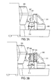
- FIG. 3A and FIG. 3B illustrate embodiments of sensor assembly 314 in a retracted and a raised position, respectively.
- FIG. 3A illustrates an embodiment of sensor assembly 314 in the retracted position where sensing plate (not shown in this view) and sensing frame (not shown in this view) are retracted below mounting base 311.
- mounting member 303 is positioned below mounting base 311.
- sensor assembly 314 can be retracted into mounting member 303 so that it does not interfere with the slicing.
- Sample 308 is shown attached to sample holder 307.
- Sample holder 307 is attached to vertical drive member 305.
- sensor assembly 314 may be raised vertically so that sensing plate 330 is aligned with sample 308 as illustrated in the embodiment of FIG . 3B .
- rail member 344 of sensing assembly 314 slides along sliding member 346 to allow sensing plate 330 to be raised above mounting member 303 so that it is positioned in front of mounting base 311.
- a rail member positioned on an opposite side of sensing assembly 314 may also slide along a corresponding sliding member.
- Sample 308 is aligned with sensing plate 330 and advanced horizontally in a direction toward sensing plate 330.
- An angular orientation of the foremost surface of sample 308 can then be detected by pressing the foremost surface of sample 308 against sensing plate 330.
- the detected angular orientation may be used to facilitate realignment of the angular orientation of foremost surface of sample 308 so that it is parallel, sufficiently parallel, or at least more parallel, to a cutting member and/or cutting plane. If desired, multiple such sensing measurements may be made at different times or repeatedly throughout the realignment process, or alternatively a single measurement and single adjustment based on that single measurement may be made.
- sensor assembly 314 may be lowered below mounting base 311 as illustrated in FIG . 3A to prepare the microtome for a sectioning operation.
- sensor assembly 114 is positioned horizontally between support member 115 and cutting member 112 and/or cutting plane 124.
- Sensor assembly 114 is operable to move vertically up and down as viewed.
- One aspect associated with positioning sensor assembly 114 horizontally between support member 115 and cutting member 112 is that sample 108 may need to traverse a greater horizontal distance in the direction of horizontal arrow 125 to reach cutting member 112 and/or cutting plane 124 due in part to extra horizontal distance to accommodate a width dimension of sensor assembly 114, for example the dimension "w" shown in FIG. 1 , which may be on the order of 3cm.
- the traversal of the greater horizontal distance may take additional time, which depending upon the implementation may be undesired. For example, commonly the movement in the horizontal direction is relatively slower than in the vertical direction. This may be a result of a desire to provide a finer accuracy of movement in the horizontal direction in order to provide accurate horizontal positions to achieve accurate control over sectioning thickness.
- sensor assembly 114 is not horizontally disposed between sample 108 and/or support member 115 and cutting mechanism 112.
- sensor assembly 114 may be in a fixed positioned approximately vertically below cutting member or mechanism 112 and/or cutting plane 124.
- One potential advantage to positioning sensor assembly 114 vertically below cutting member 112 is that sample 108 may not need to traverse additional distance (e.g., on the order of 3cm) in the horizontal direction of arrow 125 to reach cutting member 112 and/or cutting plane 124. This may help to reduce the amount of time for sample to move horizontally to cutting member 112.
- vertical movement of vertical drive member 105 may be relatively faster than horizontal movement of horizontal drive member 106.
- Vertical drive member 105 may move down an additional distance (e.g., on the order of 64cm) in the direction of vertical arrow 126 to reach sensor assembly 114. In some cases, it may take less time for vertical drive member 105 to travel the extra distance in the vertical direction to reach sensor assembly 114 below cutting mechanism 112 than it would take for horizontal drive member 106 to travel the extra distance in the horizontal direction due to the width of sensor assembly 114. This may help to speed up the time to sense surface orientations and adjust the surface orientations.
- additional distance e.g., on the order of 64cm
- an initial position of the foremost surface of the sample may be detected by pressing the sample against the sensing plate. Based on the degree of rotation of the sensing plate and the sensing frame about their respective axis, an angular orientation and position of the surface of the sample can be determined.
- the various axis and rotation of the sensing plate and sensing frame about their axis are illustrated in the embodiments of FIGs . 4A , 4B , 4C and 4D .
- FIG. 4A illustrates a cut out perspective view of an embodiment of sensor assembly 414 having a first axis of a sensing plate.
- FIG. 4B illustrates a cross sectional view of an embodiment of sensor assembly 414 of FIG. 4A along line B--B'.
- sensor assembly 414 includes sensing plate 430 and sensing frame 431 attached to sensing assembly frame 438.
- First axial support member 432 is positioned diagonally through sensing plate 430 to provide a first axis of rotation for sensing plate 430 at an angle of rotation ( ⁇ ).
- a second axial support member 433 (shown in FIG. 4D ) is positioned diagonally though sensing frame 431 to provide a second axis of rotation for sensing frame 431.
- the second axis of rotation is substantially perpendicular to the first axis of rotation (for example 80-100 degrees).
- a foremost or cutting surface of sample block 408 (e.g., a tissue sample embedded in a paraffin block or cassette) is pressed against sensing plate 430.
- the surface of sample block 408 is not parallel to a cutting member and/or cutting plane.
- Pressing the surface of sample block 408 against sensing plate 430 causes rotation of sensing plate 430 along first axial support member 432 as illustrated in FIG. 4B so that sensing plate 430 conforms to an angular orientation of the surface of sample block 408.
- the degree of rotation of sensing plate 430 along first axial support member 432 is detected by sensing plate sensor 430 attached to sensing assembly frame 438. This information is then used in part to determine the angular orientation of the surface of sample block 408.
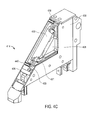
- FIG. 4C illustrates a cut out perspective view of an embodiment of a sensor assembly 414 having sensing frame 431 with a second axis of rotation about second axial support member 433.
- Sensing frame 431 may rotate about the second axis of rotation at an angle ( ⁇ ).
- FIG. 4D illustrates a cross sectional view of an embodiment of sensor assembly 414 of FIG. 4C along line D--D'.
- second axial support member 433 is positioned diagonally through sensing frame 431 and substantially perpendicular to first axial support member 432 (for example 80-100 degrees).
- sensing frame 431 will rotate about second axial support member 433 as illustrated in the embodiment of FIG. 4D .
- the degree of rotation may be detected by sensing frame sensor 436 attached to sensing assembly frame 438. This information may be combined with the information relating to the degree of rotation of sensing plate 430 to determine the angular orientation of the foremost or cutting surface of sample block 408.
- First biasing member 439 and second biasing member 440 to allow movement of sensing frame 431 in a horizontal direction are further illustrated in FIG. 4C .
- First biasing member 439 and second biasing member 440 may be positioned along opposite ends of second axial support member 433 to bias second axial support member 433 in a horizontal direction towards of sample block 408.
- first biasing member 439 and second biasing member 440 may be springs, pneumatic cylinders, or the like.
- the degree of movement in this direction may optionally be detected using an optional sensor, for example an optical sensor, mechanical sensor, magnetic field sensor, or the like, positioned at each end of second axial support member 433.
- the optical sensors may detect a degree of movement of second axial support member 433 in the horizontal direction away from sample block 408.
- This horizontal displacement information may be used in addition to the information relating to the amount of rotation of sensing plate 430 and sensing frame 431 to determine not only an angular orientation of the foremost surface of sample block 408 but also a horizontal position of the foremost surface of sample block 408.
- knowing the horizontal position of the foremost surface of sample block 408 may help to achieve a cut of an intended thickness.
- sensing plate 430 and sensing frame 431 may each detect an angle of the surface of sample block 408 (with respect to the cutting plane) of up to about five degrees (for example), along their respective axis.
- sensing plate 430 may rotate about first axial support member 432 up to about five degrees (5°) from an initial position parallel to the cutting plane.
- sensing frame 431 may rotate about second axial support member 433 up to about five degrees (5°) from an initial position parallel to the cutting plane.
- sensing plate 430 and/or sensing frame 431 may cause sensing plate 430 and/or sensing frame 431 to rotate to a degree equivalent to the degree to which the surface of sample block 408 is offset from the cutting plane.
- Sensing plate 430 and sensing frame 431 may detect a combined angle of up to about seven degrees (7°), in this particular embodiment, to determine an overall angular orientation that the surface of sample block 408 is offset from the cutting plane.
- the microtome may autonomously determine an adjustment, and autonomously adjust the angular orientation of the surface of the sample block 408 by the determined adjustment, so that it is parallel, substantially parallel, or more parallel relative to cutting member and/or cutting plane. For example, if it is determined that the surface of sample block 408 is offset from the cutting plane at a total angle of approximately four degrees (4°), then the surface of sample block 408 may be rotated approximately four degrees (4°) in the opposite direction so that the surface of sample block 408 is approximately parallel to the cutting plane. If desired, multiple sensing measurements may be made while the angle is gradually decreased in small adjustments. It is to be understood that other embodiments may utilize either greater or lesser degrees of rotation than the particular degrees of rotation described for this example embodiment.
- the horizontal position of foremost surface of sample block 408 may be detected using a sensor to sense the horizontal movement of sensing frame 431 when sample block 408 is pressed against sensing plate 430. Knowing the horizontal position of the foremost surface of sample block 408 may allow microtome to make initial cuts of a desired thickness.
- Sensor assemblies 214, 314, and 414 shown in FIG. 2 , FIG. 3A-3B , and FIG. 4A , 4B , 4C , and 4D , respectively, represent example embodiments of suitable surface orientation sensors.
- other surface orientation sensors are also contemplated.
- Some of these alternate surface orientation sensors are contact-based sensors or sensor assemblies analogously to sensor assemblies 214, 314, and 414 described above. However, they may make use of different contact-based sensing mechanisms for sensing the orientation of the surface of the sample.
- a sensing plate may be mounted on a single pivot (for example a ball joint), which allows the sensing plate to rotate in two dimensions to conform to an orientation of the cutting surface of the sample.
- Still other contemplated surface orientation sensors are non-contact-based sensors that need not contact the surface of the sample to determine an orientation of the surface of the sample.
- an optical sensing system may optically sense the orientation of the surface of the sample, for example by directing or scanning one or more laser beams onto the surface.
- Other approaches may be based on acoustics, interferometry, etc.
- the feed drive system may have a multi-axis workpiece chuck or motorized chuck that is capable of adjusting an orientation of the cutting surface of the sample in two dimensions relative to a cutting member and/or cutting plane.
- suitable multi-axis workpiece chucks are described in U.S. Patent 7,168,694 , entitled "MULTI-AXIS WORKPIECE CHUCK,” by Xuan S. Bui et al., filed on January 22, 2004, and assigned to the assignee of the present application.
- the multi-axis chuck may have a mounting assembly that retains a workpiece, such as a sample, in a substantially fixed orientation with respect to the chuck.
- the chuck may be motor-driven and may be rotatable about at least two axes which may be perpendicular.
- the chuck may be rotated manually by an operator using a controller that is in communication with one or more motors, or the microtome may autonomously rotate the chuck.
- One or more sensors may be used to sense a position of the chuck.
- each axis may have three sensors that detect a middle nominal position and end positions of the chuck.
- a user or the microtome may control movement of the chuck by signaling the motor to rotate the chuck to the desired position.
- the chuck may include first and second portions that are rotatable about at least two orthogonal axes.
- the first portion may rotate about a first axis and independently of the second portion. Rotation of the second portion about a second axis may cause the first portion to rotate about the second axis also. This may allow the chuck to be rotatable in multiple dimensions.
- a locking mechanism may also optionally be provided. After rotating the multi-axis chuck, a locking mechanism may be engaged to lock the multi-axis chuck in the desired position.
- This locking mechanism may be, for example, a permanent magnet solenoid, a geared motor or a rotating handle that causes the first, second, and third portions to lock by friction or other known manner.
- a motor may be used to tighten the chuck at times when the chuck is not being adjusted.
- the motor may be signaled to loosen the chuck to allow the chuck to be adjusted.
- the motor may be signaled to maintain the chuck in a tightened or locked configuration so that the position of the chuck and/or the position of a sample held by the chuck do not change unintentionally.
- a sectioning cycle may include: (1) moving sample block 408 in a forward horizontal direction toward the cutting plane a predetermined distance related to the desired slice thickness; (2) moving sample block 408 in a vertical direction (for example downward) toward the cutting member to obtain a slice; (3) moving the sample block 408 in a backward or opposite horizontal direction away from the cutting plane and/or cutting member a predetermined distance; and (4) moving sample block 408 in an opposite vertical direction (for example upward) away from the cutting member. Retracting or moving the sample block 408 in a backward horizontal direction away from the cutting member helps to avoid sample block 408 contacting the cutting member during (4) when moving sample block 408 in the opposite vertical direction (for example upward) away from the cutting member.
- the distance sample block 408 is retracted may correspond to a thickness of the sliced sample.
- the retraction step may be omitted.
- the slicing cycle may be repeated until a desired number of slices are obtained.
- a microtome may be capable of using different speeds of movement of a feed drive system and/or a sample (e.g., sample block 410 in FIG. 4A or sample 108 in FIG. 1 ) for different portions of a sectioning cycle.
- a relatively faster speed of movement of the feed drive system and/or a sample may be used during one or more non-sectioning portions of a sectioning cycle (e.g., where cutting or sectioning of a sample is not performed), whereas a relatively slower speed of movement of the feed drive system and/or a sample may be used during a sectioning portion of the sectioning cycle (e.g., where cutting or sectioning of the sample is performed).
- Using a relatively slower speed of movement of the feed drive system and/or sample during cutting or sectioning of the sample tends to provide higher quality sections and/or more consistent sections, whereas performing one or more other non-sectioning portions of the sectioning cycle more rapidly may help to improve the overall speed of the sectioning cycle and/or may allow more sections to be produced in a given amount of time.
- the speed of movement of a feed drive system and/or a sample may vary throughout a sectioning cycle.
- a user may control or program a sectioning cycle so that movement of sample block 410 or sample 108 in a vertical direction (for example downward) toward the cutting member to obtain a slice (e.g., operation (2) in the paragraph above) is performed more slowly than one or more other portions of the sectioning cycle (e.g., operations (1), (3), (4), or a combination thereof, in the paragraph above).
- a slice e.g., operation (2) in the paragraph above
- one or more other portions of the sectioning cycle e.g., operations (1), (3), (4), or a combination thereof, in the paragraph above.
- a microtome may include logic to allow a configurable or programmable sectioning portion of a sectioning cycle to be specified over which relatively slower speed of movement of the feed drive system and/or a sample are to be used.
- the microtome may include logic to allow a configurable or programmable sectioning length to be configured or programmed.
- the length may be selected from among a plurality of predetermined lengths corresponding to different types of cassettes having different dimensions. Different types of cassettes have different sectioning lengths over which sectioning is performed.
- the microtome may be operable to allow an operator to specify or indicate a sectioning length.
- the specification or indication of the sectioning length may be done in different ways, such as, for example, by specifying a length, selecting a length from among a plurality of predetermined lengths, specifying a type of cassette, selecting a type of cassette from among a plurality of different types of cassettes, etc.
- the user may make a selection of the particular type of cassette using a control device (e.g., control device 116 in FIG. 1 ), and the microtome may already be preprogrammed with a predetermined sectioning length corresponding to that particular type of cassette.
- the microtome may use a relatively slower speed of movement of the feed drive system and/or the sample over the specified sectioning length and may use relatively faster speeds of movement over one or more or substantially all other portions of the sectioning cycle. For example, immediately or just before and immediately or just after the cutting of the sample over the specified sectioning length the relatively faster speeds may be used.
- a microtome may include logic to initially autonomously remove a given or predetermined portion of a sample (e.g., sample 108 in FIG. 1 or sample block 408 in FIG. 4A ).
- the portion may include a given or predetermined thickness of paraffin, embedding material, cassette material, or other non-tissue material overlying or concealing the actual tissue material from which a section is desired to be taken (e.g., disposed between a cutting surface of the tissue material and the foremost external surface of the sample which would contact a sensing plate).
- a sample may include a piece of tissue placed on a bottom of a cassette and the cassette and the tissue sample embedded in a block of embedding material.
- the cassettes may include a Paraform® brand cassette material that has sectioning characteristics similar to that of paraffin and sectioning may be performed through the Paraform® brand cassette material of the cassette bottom.
- a microtome may include logic to initially autonomously remove a given or predetermined portion of a sample, for example, a portion of paraffin, embedding material, cassette material, or other non-tissue material overlying or concealing an actual tissue material desired to be sectioned.
- the microtome may autonomously remove a bottom of a cassette in order to expose or provide access to the actual tissue material of the sample.
- the microtome may autonomously make a plurality (e.g., from around two to about twenty, often from about five to about fifteen) of sections to remove a predetermined thickness of the bottom of the cassette.
- the thickness of the bottom of the cassette may be known by the microtome or predetermined. For example, a user may specify the thickness directly, or select a type of cassette from among several different types that each has a preprogrammed or otherwise known cassette bottom thickness.
- the operator may control the microtome to perform the automated process, for example, with a user input device (e.g., a trim button) on a control device or otherwise selecting a trim operation.
- a user input device e.g., a trim button
- allowing the microtome to autonomously remove the portion of the sample may relive the operator from having to do so and/or may tend to speed up the removal of the portion of the sample (e.g., the bottom of the cassette).
- a sectioning cycle to obtain slices or sections of the tissue may be commenced (e.g., the operator may press a section button or otherwise cause the microtome to take a section from the now exposed cutting surface of the tissue sample.
- FIG. 5 illustrates an embodiment of a control system for controlling an operation of the microtome including a handwheel and control device.
- Control system 560 may include handwheel 504 and control device 516.
- Handwheel 504 may include handle or other pulse generating device 517 to lock handwheel 504.
- handwheel 504 is coupled to motor 510 using a non-mechanical coupling or non-mechanical mechanism (for example an electrical coupling).
- microtomes include a handwheel that is mechanically coupled to the motor. Such mechanical coupling, however, adds resistance to the handwheel when the user tries to turn it.
- the non-mechanical coupling or mechanism disclosed herein may offer the advantage of reduced handwheel resistance resulting in a handwheel that is easier to turn.
- the non-mechanical coupling or mechanism includes first encoder 561.
- First encoder 561 may be a rotary encoder coupled to shaft 562 of handwheel 504. Rotation of handwheel 504 and in turn shaft 562 provides first encoder 561 with an angular position of handwheel 504.
- First encoder 561 then converts the angular position to an electrical representation (for example an analog or digital code or value). This analog or digital code is transmitted to control circuit 518 via control line 519 where it is processed and used to direct movement of motor 510 and in turn feed drive 502.
- motor 510 having feed drive 502 coupled thereto may be connected to control circuit 518 by second encoder 564.
- shaft 563 of motor 506 may be connected to second encoder 564 so that second encoder 564 may detect a position of motor 510 during the cutting operation. Encoder 564 then converts this position information to an electrical representation (for example an analog or digital code or value) and transmits the electrical representation to control circuit 518 via control line 520.
- control circuit 518 may control the motor based at least in part on the electrical representation of the angular position of the handwheel. For example, since positions of both handwheel 504 and motor 510 are known, control circuit 518 can ensure that the position of handwheel 504 corresponds to, and is in alignment with, the position of motor 510 during a cutting operation.
- rotation of handwheel 504 may not cause movement of motor 510 until a comparison of signals from the respective first and second encoders indicate that a position of handwheel 504 is aligned with a position of drive shaft of motor 510. This may tend to increase safety of operation of the microtome, especially when transferring from an automated mode of sectioning to a manual mode of sectioning.
- Control device 516 may further be operable to initiate an automated cutting operation.
- Control device 516 may be any type of input device suitable for initiating a cutting operation.
- control device 516 may include, for example, a keyboard, a keypad, a capacitive sensor touch pad, or other user data input device.
- signals are transmitted between control device 516 and control circuit 518 via control line 523.
- control device 516 may be a wireless control device that is operable to transmit wireless control signals to control circuit 518 and optionally receive wireless signals from control circuit 518.
- the control line 523 may be omitted.
- Wireless control device 516 may have a wireless transmitter, wireless receiver, and/or wireless transceiver, a wireless protocol stack, and other conventional components found in wireless devices.
- wireless control device 516 may be a Bluetooth capable device, although this is not required.
- Control device 516 may include keys or simulated keys that can be used to control the actions of the microtome.
- the keys may present graphic symbols or text corresponding to the various operations of the microtome, such as arrows corresponding to a vertical or horizontal movement of the microtome and/or other words, symbols, pictures, or the like, corresponding to, for example, slicing, stop, start, trim a bottom of a cassette, section, locking, or other microtome operations.
- the user selects the operation to be performed using the control device 516 and pushes the appropriate key(s) to initiate the desired operation.
- the control signal is transmitted from control device 516 to control circuit 518.
- Control circuit 518 then provides a signal to, for example, motor 510 to initiate a cutting operation.
- the cutting operation may then continue automatically or autonomously substantially without additional user intervention until the user either presses a stop key or a preprogrammed cutting operation is completed.
- FIG. 6 illustrates a perspective view of an embodiment of a feed drive system of a microtome.
- feed drive system 602 may be used for feed drive system 102 described in reference to FIG. 1 .
- feed drive system 102 may use an entirely different feed drive system than feed drive system 602.
- Feed drive system 602 includes vertical drive member 605, horizontal drive member 606 and sample holder 607.
- Mounting member 603 for holding a cutting member may further be positioned in front of sample holder 607.
- mounting member 603 may be substantially similar to mounting member 103 described in reference to FIG. 1 .
- feed drive system 602 During operation, vertical movement of feed drive system 602 is achieved by moving a slider (not shown) of vertical drive member 605 vertically along a track. Movement of the slider is caused by rotating pin (not shown) attached to a rotating plate (not shown) which is turned by driving belt 671 and motor (not shown).
- the weight of feed drive system 602 may be counter-balanced.
- the weight may be counterbalanced using spring assembly 672 instead of a counterweight. Counterweights tend to be heavy and tend to increase the weight and cost of the microtome. Alternatively, a counterweight may be used if desired.
- Spring assembly 672 may include pulleys 673-1, 673-2, 673-3.
- Pulley 673-1 may be attached to pin 670.
- Cable 674 may be attached at one end to pulley 673-1, extend around pulleys 673-2 and 673-3 and be attached at the opposite end to springs 675.
- springs 675 exert a counter-balancing force on cable 674, which in turn pulls on pin 670 and counters the weight of feed drive system 602.
- Spring assembly 672 may help to reduce the weight of the system by eliminating a counterweight and may help to reduce the inertia load on the motor.
- spring assembly 672 is described in one embodiment, it is further contemplated that in other embodiments, a half-circle heavy mass attached to pin 670 may be used to counter-balance feed drive system 602. Although a half-circle heavy mass is also effective at counter-balancing feed drive system 602, it tends to increase the inertia load to the motor.
- a microtome may optionally include a lock that is operable to lock a feed drive system (e.g., feed drive system 104 in FIG. 1 or feed drive system 602 in FIG. 6 ) in a vertical position.
- the lock may include a spring biased disc brake.
- the spring biased disc brake may include a disc brake, a pin or other locking member, and one or more springs or other mechanical biasing elements to bias the pin or other locking member into a locking engagement with the disc brake when a deliberate unlock signal is not applied.
- Other types of locks known in the arts are also suitable, such as, for example, a pin or other locking member biased into a hole.
- the lock may hold the feed drive system in a fixed, locked vertical position when the lock is not deliberately disabled.
- an unlock signal (e.g., an electrical signal) may be deliberately applied to the lock, to open the lock (e.g., compress the spring, which may unlock the disc brake).
- an unlock signal e.g., an electrical signal
- such a lock may help to prevent or at least reduce the likelihood that an operator is harmed due to a moving or falling feed drive system, for example in the event of a power failure or otherwise. Without such a lock, the operator may be damaged by the blade or other cutting member if the feed drive system were to fall or move unexpectedly.
- One or more embodiments include an article of manufacture (e.g., a computer program product) that includes a machine-accessible and/or machine-readable medium.
- the medium may include, a mechanism that provides (e.g., stores) information in a form that is accessible and/or readable by the machine.
- the machine-accessible and/or machine-readable medium may provide, or have stored thereon, a sequence of instructions and/or data structures that if executed by a machine causes or results in the machine performing, and/or causes the machine to perform, one or more or a portion of the operations or methods disclosed herein.
- the machine-readable medium may include a tangible non-transitory machine-readable storage media.
- the tangible non-transitory machine-readable storage media may include a floppy diskette, an optical storage medium, an optical disk, a CD-ROM, a magnetic disk, a magneto-optical disk, a read only memory (ROM), a programmable ROM (PROM), an erasable-and-programmable ROM (EPROM), an electrically-erasable-and-programmable ROM (EEPROM), a random access memory (RAM), a static-RAM (SRAM), a dynamic-RAM (DRAM), a Flash memory, a phase-change memory, or a combinations thereof
- the tangible medium may include one or more solid or tangible physical materials, such as, for example, a semiconductor material, a phase change material, a magnetic material, etc.
Landscapes
- Physics & Mathematics (AREA)
- Health & Medical Sciences (AREA)
- Life Sciences & Earth Sciences (AREA)
- Chemical & Material Sciences (AREA)
- Analytical Chemistry (AREA)
- Biochemistry (AREA)
- General Health & Medical Sciences (AREA)
- General Physics & Mathematics (AREA)
- Immunology (AREA)
- Pathology (AREA)
- Sampling And Sample Adjustment (AREA)
Priority Applications (2)
| Application Number | Priority Date | Filing Date | Title |
|---|---|---|---|
| EP17173912.1A EP3239687B1 (de) | 2011-03-24 | 2012-03-15 | Oberflächenorientierungssensor zur erfassung der orientierung der oberfläche einer probe |
| DK17173912.1T DK3239687T3 (da) | 2011-03-24 | 2012-03-15 | Overfladeorienteringssensor til at detektere orientering af en overflade af en prøve |
Applications Claiming Priority (1)
| Application Number | Priority Date | Filing Date | Title |
|---|---|---|---|
| US13/071,185 US8869666B2 (en) | 2011-03-24 | 2011-03-24 | Microtome with surface orientation sensor to sense orientation of surface of sample |
Related Child Applications (2)
| Application Number | Title | Priority Date | Filing Date |
|---|---|---|---|
| EP17173912.1A Division EP3239687B1 (de) | 2011-03-24 | 2012-03-15 | Oberflächenorientierungssensor zur erfassung der orientierung der oberfläche einer probe |
| EP17173912.1A Division-Into EP3239687B1 (de) | 2011-03-24 | 2012-03-15 | Oberflächenorientierungssensor zur erfassung der orientierung der oberfläche einer probe |
Publications (3)
| Publication Number | Publication Date |
|---|---|
| EP2503315A2 true EP2503315A2 (de) | 2012-09-26 |
| EP2503315A3 EP2503315A3 (de) | 2013-01-02 |
| EP2503315B1 EP2503315B1 (de) | 2017-07-19 |
Family
ID=46027545
Family Applications (2)
| Application Number | Title | Priority Date | Filing Date |
|---|---|---|---|
| EP17173912.1A Active EP3239687B1 (de) | 2011-03-24 | 2012-03-15 | Oberflächenorientierungssensor zur erfassung der orientierung der oberfläche einer probe |
| EP12159609.2A Active EP2503315B1 (de) | 2011-03-24 | 2012-03-15 | Mikrotom mit Oberflächenorientierungssensor zur Erfassung der Orientierung der Oberfläche von Proben |
Family Applications Before (1)
| Application Number | Title | Priority Date | Filing Date |
|---|---|---|---|
| EP17173912.1A Active EP3239687B1 (de) | 2011-03-24 | 2012-03-15 | Oberflächenorientierungssensor zur erfassung der orientierung der oberfläche einer probe |
Country Status (9)
| Country | Link |
|---|---|
| US (2) | US8869666B2 (de) |
| EP (2) | EP3239687B1 (de) |
| JP (2) | JP5960457B2 (de) |
| CN (1) | CN102692338B (de) |
| AU (1) | AU2012200721C9 (de) |
| BR (1) | BR102012006505B1 (de) |
| CA (1) | CA2766756C (de) |
| DK (2) | DK2503315T3 (de) |
| ES (2) | ES2802542T3 (de) |
Cited By (7)
| Publication number | Priority date | Publication date | Assignee | Title |
|---|---|---|---|---|
| WO2013095972A3 (en) * | 2011-12-21 | 2013-08-15 | Sakura Finetek U.S.A., Inc. | Reciprocating microtome drive system |
| US8869666B2 (en) | 2011-03-24 | 2014-10-28 | Sakura Finetek U.S.A., Inc. | Microtome with surface orientation sensor to sense orientation of surface of sample |
| WO2015154738A1 (de) | 2014-04-11 | 2015-10-15 | Hans Heid | Mikrotom und verfahren zum betrieb eines mikrotoms |
| EP3066447A4 (de) * | 2013-11-05 | 2017-06-07 | Howard Hughes Medical Institute | Sezierung von volumenproben |
| AT518719A1 (de) * | 2016-05-19 | 2017-12-15 | Luttenberger Herbert | Mikrotom |
| RU188389U1 (ru) * | 2018-11-15 | 2019-04-09 | федеральное государственное бюджетное образовательное учреждение высшего образования "Омский государственный медицинский университет" Министерства здравоохранения Российской Федерации (ФГБОУ ВО ОмГМУ Минздрава России) | Адгезивная подложка для ориентировки биопсийного материала слизистой оболочки желудка |
| GB2618378A (en) * | 2022-05-06 | 2023-11-08 | The Francis Crick Institute Ltd | Optical measurement apparatuses for use with a cutting apparatus |
Families Citing this family (21)
| Publication number | Priority date | Publication date | Assignee | Title |
|---|---|---|---|---|
| DE102010046498B3 (de) * | 2010-09-24 | 2011-12-15 | Hans Heid | Schneidehubverstellung eines Rotationsmikrotoms |
| DE102013203564B3 (de) * | 2013-03-01 | 2013-12-05 | Leica Biosystems Nussloch Gmbh | Probenhalter eines Mikrotoms |
| US9097629B2 (en) * | 2013-03-15 | 2015-08-04 | Leica Biosystems Nussloch Gmbh | Tissue cassette with retractable member |
| GB2514774B (en) * | 2013-06-03 | 2016-02-24 | Primetals Technologies Ltd | A shear |
| DE102013110776B4 (de) | 2013-09-30 | 2015-05-13 | Leica Biosystems Nussloch Gmbh | Verfahren und Mikrotom zum Herstellen von Dünnschnitten mit einem Schnittprofilaufzeichnungsmodus |
| CA2929890C (en) * | 2013-12-30 | 2023-01-24 | Kurt HEMMINGS | Tool and method for aligning a tissue plane for microtomy |
| US10571368B2 (en) | 2015-06-30 | 2020-02-25 | Clarapath, Inc. | Automated system and method for advancing tape to transport cut tissue sections |
| US10473557B2 (en) | 2015-06-30 | 2019-11-12 | Clarapath, Inc. | Method, system, and device for automating transfer of tape to microtome sections |
| US10724929B2 (en) | 2016-05-13 | 2020-07-28 | Clarapath, Inc. | Automated tissue sectioning and storage system |
| CN106078848B (zh) * | 2016-06-30 | 2018-03-30 | 中国人民解放军国防科学技术大学 | 一种制备骨骼样本的切割机床 |
| US11112337B2 (en) * | 2016-11-14 | 2021-09-07 | Sakura Finetek U.S.A., Inc. | Microtome with generator |
| CN109656155B (zh) * | 2017-10-11 | 2023-05-12 | 徕卡显微系统(上海)有限公司 | 石蜡切片机及其控制方法 |
| DE102017128491B4 (de) * | 2017-11-30 | 2022-12-22 | Leica Biosystems Nussloch Gmbh | Mikrotom und Verfahren zum Positionieren eines Mikrotomobjektkopfes |
| KR102119782B1 (ko) * | 2018-05-10 | 2020-06-05 | (의)삼성의료재단 | 조직 절편기 |
| CN108318310A (zh) * | 2018-05-14 | 2018-07-24 | 上海交通大学医学院附属第九人民医院 | 一种激光扫描引导下用于平行切割不规则生物组织的装置 |
| US11001380B2 (en) * | 2019-02-11 | 2021-05-11 | Cnh Industrial Canada, Ltd. | Methods for acquiring field condition data |
| US11059582B2 (en) | 2019-02-11 | 2021-07-13 | Cnh Industrial Canada, Ltd. | Systems for acquiring field condition data |
| US20210263055A1 (en) | 2020-02-22 | 2021-08-26 | Clarapath, Inc. | Facing and Quality Control in Microtomy |
| EP4232792A1 (de) | 2020-10-23 | 2023-08-30 | Clarapath, Inc. | Vordiagnosen geschnittener gewebeschnitte |
| WO2022241261A1 (en) * | 2021-05-13 | 2022-11-17 | Clarapath, Inc. | Systems and methods for section transfer |
| CN115070847A (zh) * | 2022-06-09 | 2022-09-20 | 金华市益迪医疗设备有限公司 | 组织自动切片速度分段控制装置和控制方法 |
Citations (1)
| Publication number | Priority date | Publication date | Assignee | Title |
|---|---|---|---|---|
| US7168694B2 (en) | 2004-01-22 | 2007-01-30 | Sakura Finetek U.S.A., Inc. | Multi-axis workpiece chuck |
Family Cites Families (108)
| Publication number | Priority date | Publication date | Assignee | Title |
|---|---|---|---|---|
| US2155523A (en) | 1935-04-26 | 1939-04-25 | Bausch & Lomb | Microtome |
| US3273879A (en) | 1963-09-13 | 1966-09-20 | Olaf J Floren | Compound sine plate |
| US3962937A (en) | 1974-07-18 | 1976-06-15 | Miller Leo C | Error adjustment method and structure for lathes and the like |
| US3926085A (en) | 1974-12-02 | 1975-12-16 | American Optical Corp | Specimen feed for a microtome |
| US4150593A (en) | 1978-04-21 | 1979-04-24 | Butler James K | Retractable specimen holder for a rotary microtome |
| DE3218492C2 (de) * | 1982-05-15 | 1985-06-20 | Breitfeld & Schliekert, 6368 Bad Vilbel | Maschine zum Herstellen von Kopierschablonen zum Randschleifen von Brillengläsern |
| DE3404098C1 (de) | 1984-02-07 | 1990-02-15 | Parke, Davis & Co., Morris Plains, N.J. | Mikrotom mit einer Objektrueckzugeinrichtung |
| DE3830725A1 (de) * | 1988-09-09 | 1990-03-22 | Leitz Wild Gmbh | Automatische arretierung der antriebseinrichtung eines mikrotoms |
| SE500941C2 (sv) * | 1989-08-16 | 1994-10-03 | Algy Persson | Förfarande och apparat för snittning av ett preparat |
| USD326860S (en) | 1989-08-29 | 1992-06-09 | Leica Instruments Gmbh | Microtome tool holder |
| USD328129S (en) | 1989-08-29 | 1992-07-21 | Leica Instruments Gmbh | Knife holder for a microtome |
| USD326921S (en) | 1989-10-18 | 1992-06-09 | Leica Instruments Gmbh | Rotation microtome |
| DE8914782U1 (de) | 1989-12-15 | 1990-02-08 | Cambridge Instruments Gmbh, 6907 Nussloch, De | |
| AT399226B (de) * | 1990-04-11 | 1995-04-25 | Sitte Hellmuth | Automatische anschneidevorrichtung für mikrotome, insbesondere ultramikrotome |
| WO1991015746A1 (de) | 1990-03-19 | 1991-10-17 | Hellmuth Sitte | Mikrotom |
| DE4028806C2 (de) | 1990-09-11 | 1998-08-27 | Leica Ag | Mikrotom, insbesondere Ultramikrotom mit einer Kühlkammer |
| DE4033335A1 (de) | 1990-10-19 | 1992-04-23 | Leica Instr Gmbh | Mikrotom |
| US5156019A (en) | 1990-11-19 | 1992-10-20 | Mccormick James B | Frozen tissue sectioning apparatus and method |
| USD358895S (en) | 1990-11-23 | 1995-05-30 | Leica Instruments Gmbh | Microtome |
| US5255585A (en) | 1991-09-19 | 1993-10-26 | Instrumedics, Inc. | Vacuum system for cryostats |
| US5535654A (en) * | 1991-11-28 | 1996-07-16 | Microm Laborgerate Gmbh | Microtome |
| JPH05256745A (ja) | 1992-03-16 | 1993-10-05 | Feather Safety Razor Co Ltd | ミクロトーム |
| US5965454A (en) | 1993-02-03 | 1999-10-12 | Histaggen Incorporated | Automated histo-cytochemistry apparatus and encapsulation system for processing biological materials |
| US5695942A (en) | 1993-02-03 | 1997-12-09 | Histaggen Incorporated | Automated histo-cytochemistry apparatus and encapsulation system for processing biological materials |
| FR2705917B1 (fr) | 1993-06-02 | 1995-09-08 | Tabone Herve | Microtome à aspiration, notamment pour travaux histologiques et similaires. |
| US5461953A (en) | 1994-03-25 | 1995-10-31 | Mccormick; James B. | Multi-dimension microtome sectioning device |
| RU2085892C1 (ru) | 1994-08-15 | 1997-07-27 | Илья Борисович Извозчиков | Микротом |
| USD383548S (en) | 1994-09-23 | 1997-09-09 | Leica Instruments Gmbh | Rotational microtome |
| DE9415681U1 (de) | 1994-09-28 | 1994-11-17 | Leica Instr Gmbh | Spannvorrichtung zum Klemmen von Probehaltern für ein Mikrotom |
| DE4435072C1 (de) | 1994-09-30 | 1995-10-19 | Leica Instr Gmbh | Klemmvorrichtung für ein klingenförmiges Schneidmesser eines Mikrotoms |
| DE4434937C1 (de) | 1994-09-30 | 1995-11-02 | Leica Instr Gmbh | Kryostat-Mikrotom mit einer Abdeckeinrichtung |
| DE19506837C1 (de) | 1995-02-28 | 1996-07-04 | Leica Instr Gmbh | Messerhalter zur Aufnahme von keilförmigen Mikrotom-Messern |
| DE19531524C1 (de) | 1995-08-26 | 1996-07-04 | Leica Instr Gmbh | Rotationsmikrotom mit einem Kurbelgetriebe |
| US5671648A (en) | 1996-01-16 | 1997-09-30 | Dern; Klaus | Rotary microtome with horizontal sweep |
| DE19604001C2 (de) | 1996-02-05 | 1998-07-16 | Leica Instr Gmbh | Einrichtung zur Orientierung eines gekühlten Objektkopfes in einem Kryostat-Mikrotom |
| US5817032A (en) | 1996-05-14 | 1998-10-06 | Biopath Automation Llc. | Means and method for harvesting and handling tissue samples for biopsy analysis |
| US5678465A (en) | 1996-06-10 | 1997-10-21 | Krumdieck; Carlos | Tissue slice thickness measuring apparatus and method |
| WO1998004898A1 (de) | 1996-07-29 | 1998-02-05 | Leica Instruments Gmbh | Scheiben-mikrotom |
| DE19635538C1 (de) | 1996-09-02 | 1998-01-22 | Leica Instr Gmbh | Messerhalter zur Aufnahme von keilförmigen Mikrotom-Messern oder von keilförmigen Klingenhaltern |
| US5839091A (en) | 1996-10-07 | 1998-11-17 | Lab Vision Corporation | Method and apparatus for automatic tissue staining |
| DE19645107C2 (de) | 1996-11-01 | 1999-06-24 | Leica Ag | Mikrotom mit einem oszillierenden Messer |
| DE19647663C1 (de) | 1996-11-19 | 1998-03-12 | Leica Instr Gmbh | Einbettautomat zur Behandlung von Proben für histologische Untersuchungen, insbesondere zur Schnittpräparation |
| DE19647662C1 (de) | 1996-11-19 | 1998-03-12 | Leica Instr Gmbh | Antriebseinrichtung für einen Einbettautomaten zur Behandlung von Proben für histologische Untersuchungen |
| JPH10197418A (ja) | 1997-01-10 | 1998-07-31 | Chuo Seiki Kk | ミクロトーム |
| DE19803966B4 (de) | 1997-03-07 | 2006-05-11 | Microm International Gmbh | Absaugeinrichtung für Schnittabfälle bei einem Kryostat-Mikrotom und Kryostat-Mikrotom |
| US6644162B1 (en) | 1998-02-18 | 2003-11-11 | Shandon Scientific Limited | Microtome |
| DE19816375C1 (de) | 1998-04-11 | 1999-07-08 | Leica Microsystems | Kassetten-Einspanneinrichtung für ein Mikrotom |
| AT406309B (de) | 1998-09-01 | 2000-04-25 | Leica Mikrosysteme Ag | Vorrichtung zur regelung der temperaturen in einer kühlkammer für ein mikrotom |
| DE19911163C1 (de) * | 1999-03-12 | 2000-07-20 | Leica Microsystems | Mikrotom |
| DE19911005A1 (de) | 1999-03-12 | 2000-09-28 | Leica Microsystems | Verfahren zur Steuerung eines Scheibenmikrotoms |
| DE19911173C2 (de) * | 1999-03-12 | 2002-01-31 | Leica Microsystems | Mikrotom mit einem motorischen Zustellantrieb |
| US6387653B1 (en) | 1999-04-09 | 2002-05-14 | Culterra, Llc | Apparatus and method for automatically producing tissue slides |
| DE19918442B4 (de) | 1999-04-23 | 2005-04-14 | Leica Microsystems Nussloch Gmbh | Färbeautomat zum Einfärben von Objekten zur mikroskopischen Untersuchung |
| DE10006084B4 (de) | 2000-02-11 | 2009-01-02 | Leica Biosystems Nussloch Gmbh | Färbeautomat mit einer Heizstation |
| US7374907B1 (en) | 2000-04-07 | 2008-05-20 | John Voneiff | System and method for automatically processing tissue samples |
| DE10048724B4 (de) | 2000-09-29 | 2008-12-04 | Leica Biosystems Nussloch Gmbh | Einrichtung zum strecken von Kryostatschnitten |
| DE10106033A1 (de) | 2001-02-09 | 2002-08-29 | Hess Consult Gmbh | Mikrotom |
| DE10115066B4 (de) | 2001-03-27 | 2012-10-04 | Leica Biosystems Nussloch Gmbh | Vorrichtung zum Trocknen lösungsmittelbasierender Tinte |
| DE10115065A1 (de) | 2001-03-27 | 2002-10-02 | Leica Microsystems | Verfahren und Vorrichtung zum Bedrucken von Kassetten oder Objektträgern für histologische Präparate |
| DE20111599U1 (de) | 2001-07-11 | 2001-09-13 | Leica Microsystems | Spender für dünne Messer, insbesondere für dünne Austausch-Mikrotommesser |
| US7371346B2 (en) | 2001-10-01 | 2008-05-13 | Leica Biosystems Melbourne Pty Ltd | Histological tissue specimen treatment |
| JP3576136B2 (ja) * | 2001-11-30 | 2004-10-13 | 堂阪イーエム株式会社 | 試験片切断装置 |
| DE10210408B4 (de) | 2002-03-09 | 2010-07-08 | Leica Biosystems Nussloch Gmbh | Mikrotom mit Vorschubeinrichtung |
| US6637737B1 (en) | 2002-07-31 | 2003-10-28 | Unova Ip Corp. | Workpiece micro-positioning apparatus |
| DE10242712B4 (de) | 2002-09-13 | 2004-10-21 | Leica Mikrosysteme Gmbh | Mikrotom mit einer Steuereinrichtung |
| DE10258555B4 (de) | 2002-12-14 | 2005-04-28 | Leica Mikrosysteme Gmbh Wien | Verfahren und System zum Anstellen und Schneiden eines Präparaten in einer Schneideeinrichtung |
| DE10300091A1 (de) | 2003-01-04 | 2004-07-29 | Lubatschowski, Holger, Dr. | Mikrotom |
| DE102004004355B3 (de) | 2003-04-15 | 2005-01-20 | Leica Microsystems Nussloch Gmbh | Rotationsmikrotom |
| DE10324696B4 (de) | 2003-05-28 | 2013-09-12 | Leica Biosystems Nussloch Gmbh | Orientierbare Probenhalterung mit einer Nullpunktanzeige für ein Mikrotom |
| DE10346996B3 (de) | 2003-10-07 | 2005-05-25 | Leica Mikrosysteme Gmbh | Mikrotom mit Kühlkammer |
| DE10346995B4 (de) | 2003-10-07 | 2012-04-19 | Leica Mikrosysteme Gmbh | Mikrotom mit Messerhalter |
| DE20318094U1 (de) | 2003-11-22 | 2004-02-12 | Leica Microsystems Nussloch Gmbh | Kryostat mit einer Wärmeplatte |
| DE20318093U1 (de) | 2003-11-22 | 2004-02-12 | Leica Microsystems Nussloch Gmbh | Kryostat mit einer integrierten Färbestation |
| CN1268423C (zh) | 2003-12-09 | 2006-08-09 | 中国石化集团南京化学工业有限公司 | 一种苯加氢催化剂的制备方法 |
| DE102004001475B4 (de) | 2004-01-08 | 2006-02-02 | Leica Mikrosysteme Gmbh | Verfahren zum Trimmen von Proben |
| DE202004006265U1 (de) | 2004-04-21 | 2004-06-17 | Leica Microsystems Nussloch Gmbh | Mikrotem zur Erzeugung von Dünnschnitten |
| EP1598140A1 (de) | 2004-05-19 | 2005-11-23 | Synova S.A. | Laserbearbeitung eines Werkstücks |
| US7854707B2 (en) | 2005-08-05 | 2010-12-21 | Devicor Medical Products, Inc. | Tissue sample revolver drum biopsy device |
| US7831075B2 (en) | 2005-10-20 | 2010-11-09 | Case Western Reserve University | Imaging system |
| DE202005019765U1 (de) | 2005-12-17 | 2006-02-16 | Leica Microsystems Nussloch Gmbh | Mikrotom mit einer Kühleinrichtung |
| JP4636552B2 (ja) | 2006-01-25 | 2011-02-23 | セイコーインスツル株式会社 | 自動薄切装置 |
| JP4840765B2 (ja) * | 2006-02-09 | 2011-12-21 | セイコーインスツル株式会社 | 薄切片作製装置及び薄切片の作製方法 |
| JP4548357B2 (ja) * | 2006-02-13 | 2010-09-22 | セイコーインスツル株式会社 | 自動薄切片標本作製装置及び自動薄切片標本作製方法 |
| DE102006031136B3 (de) | 2006-07-03 | 2007-07-26 | Leica Microsystems Nussloch Gmbh | Kurbelantrieb einer Welle eines Mikrotoms |
| DE102006034879B3 (de) | 2006-07-25 | 2007-07-12 | Leica Microsystems Nussloch Gmbh | Mikrotom mit einer Hebelanordnung |
| DE102006041208B4 (de) | 2006-09-02 | 2014-08-07 | Leica Biosystems Nussloch Gmbh | Messgerät für ein Vibrationsmikrotom und Vibrationsmikrotom mit einem Messgerät |
| EP1903325A3 (de) | 2006-09-21 | 2010-06-16 | Kurashiki Boseki Kabushiki Kaisha | Vorrichtung und Verfahren zur Aufbereitung geschnittener Proben |
| US20080113440A1 (en) | 2006-10-06 | 2008-05-15 | Leica Biosystems Melbourne Pty Ltd | Method and Apparatus for Tissue Sample Processing |
| DE102006054617B4 (de) | 2006-11-17 | 2017-06-01 | Leica Mikrosysteme Gmbh | Vorrichtung zum Bearbeiten einer Probe |
| JP4849405B2 (ja) | 2006-11-28 | 2012-01-11 | セイコーインスツル株式会社 | 自動薄切装置及び自動薄切方法 |
| DE102007023457B4 (de) * | 2007-05-19 | 2009-05-20 | Leica Biosystems Nussloch Gmbh | Verfahren zur automatischen Annäherung eines dünn zu schneidenden Präparates an das Messer eines Mikrotoms |
| DE202007007160U1 (de) * | 2007-05-19 | 2007-08-02 | Leica Microsystems Nussloch Gmbh | Vorrichtung zur Erzeugung von Dünnschnitten |
| DE102007026844B4 (de) * | 2007-06-06 | 2011-02-17 | Leica Biosystems Nussloch Gmbh | Vorrichtung zum Bremsen der Welle eines Mikrotoms |
| US7938379B2 (en) | 2007-07-11 | 2011-05-10 | General Electric Company | Three axis adjustable mounting system |
| JP2009083022A (ja) * | 2007-09-28 | 2009-04-23 | Sugino Mach Ltd | 噴流加工装置、および噴流加工装置における原点補正方法 |
| DE102008016165B4 (de) | 2008-03-28 | 2010-10-14 | Leica Biosystems Nussloch Gmbh | Mikrotom mit variablem Schneidehub unter Verwendung eines Linearmotors als Antrieb |
| US8001876B1 (en) | 2008-05-14 | 2011-08-23 | SAIC-Frederick, Inc. | Block alignment for microtomes |
| DE102008031137A1 (de) | 2008-07-01 | 2010-01-14 | Microm International Gmbh | Hubeinstellung für Rotationsmikrotom |
| JP5299996B2 (ja) * | 2008-09-08 | 2013-09-25 | セイコーインスツル株式会社 | 自動薄切装置 |
| DE102008047415B4 (de) | 2008-09-16 | 2010-12-02 | Leica Biosystems Nussloch Gmbh | Mikrotom zum Herstellen von Schnitten eines Objekts |
| WO2010036931A1 (en) | 2008-09-25 | 2010-04-01 | University Of Kansas Medical Center | Tissue slicer |
| DE102009006386B4 (de) | 2009-01-16 | 2011-04-14 | HLT Handel, Logistik und Technologie GmbH | Miktrotom |
| JP2010185818A (ja) * | 2009-02-13 | 2010-08-26 | Seiko Instruments Inc | 薄切片作製システム |
| AT507572B1 (de) | 2009-07-31 | 2010-06-15 | Leica Mikrosysteme Gmbh | Verfahren zur segmentansteuerung einer messerschneide |
| DE102010046498B3 (de) | 2010-09-24 | 2011-12-15 | Hans Heid | Schneidehubverstellung eines Rotationsmikrotoms |
| US8869666B2 (en) | 2011-03-24 | 2014-10-28 | Sakura Finetek U.S.A., Inc. | Microtome with surface orientation sensor to sense orientation of surface of sample |
| DE102012106845B4 (de) | 2012-07-27 | 2014-08-07 | Leica Biosystems Nussloch Gmbh | Mikrotom mit Auto-Rocking-Modus |
| US9873158B2 (en) * | 2013-03-13 | 2018-01-23 | Robert Bosch Tool Corporation | Adjustment and control features for a power tool |
-
2011
- 2011-03-24 US US13/071,185 patent/US8869666B2/en active Active
-
2012
- 2012-02-07 CA CA2766756A patent/CA2766756C/en active Active
- 2012-02-07 AU AU2012200721A patent/AU2012200721C9/en active Active
- 2012-03-15 EP EP17173912.1A patent/EP3239687B1/de active Active
- 2012-03-15 EP EP12159609.2A patent/EP2503315B1/de active Active
- 2012-03-15 DK DK12159609.2T patent/DK2503315T3/en active
- 2012-03-15 ES ES17173912T patent/ES2802542T3/es active Active
- 2012-03-15 ES ES12159609.2T patent/ES2642668T3/es active Active
- 2012-03-15 CN CN201210071976.9A patent/CN102692338B/zh active Active
- 2012-03-15 DK DK17173912.1T patent/DK3239687T3/da active
- 2012-03-19 JP JP2012061804A patent/JP5960457B2/ja active Active
- 2012-03-22 BR BR102012006505-3A patent/BR102012006505B1/pt active IP Right Grant
-
2014
- 2014-09-30 US US14/502,915 patent/US9347857B2/en active Active
-
2016
- 2016-06-22 JP JP2016123622A patent/JP6362641B2/ja active Active
Patent Citations (1)
| Publication number | Priority date | Publication date | Assignee | Title |
|---|---|---|---|---|
| US7168694B2 (en) | 2004-01-22 | 2007-01-30 | Sakura Finetek U.S.A., Inc. | Multi-axis workpiece chuck |
Cited By (13)
| Publication number | Priority date | Publication date | Assignee | Title |
|---|---|---|---|---|
| US8869666B2 (en) | 2011-03-24 | 2014-10-28 | Sakura Finetek U.S.A., Inc. | Microtome with surface orientation sensor to sense orientation of surface of sample |
| US9347857B2 (en) | 2011-03-24 | 2016-05-24 | Sakura Finetek U.S.A., Inc. | Microtome with surface orientation sensor to sense orientation of surface of sample |
| EP3370055A1 (de) | 2011-12-21 | 2018-09-05 | Sakura Finetek U.S.A., Inc. | Hubkolben-mikrotomantriebssystem |
| US9032854B2 (en) | 2011-12-21 | 2015-05-19 | Sakura Finetek U.S.A., Inc. | Reciprocating microtome drive system |
| WO2013095972A3 (en) * | 2011-12-21 | 2013-08-15 | Sakura Finetek U.S.A., Inc. | Reciprocating microtome drive system |
| US11187625B2 (en) | 2011-12-21 | 2021-11-30 | Sakura Fineiek U.S.A., Inc. | Reciprocating microtome drive system |
| US9921137B2 (en) | 2011-12-21 | 2018-03-20 | Sakura Finetek U.S.A., Inc. | Reciprocating microtome drive system |
| EP3066447A4 (de) * | 2013-11-05 | 2017-06-07 | Howard Hughes Medical Institute | Sezierung von volumenproben |
| US10054518B2 (en) | 2013-11-05 | 2018-08-21 | Howard Hughes Medical Institute | Sectioning volume samples |
| WO2015154738A1 (de) | 2014-04-11 | 2015-10-15 | Hans Heid | Mikrotom und verfahren zum betrieb eines mikrotoms |
| AT518719A1 (de) * | 2016-05-19 | 2017-12-15 | Luttenberger Herbert | Mikrotom |
| RU188389U1 (ru) * | 2018-11-15 | 2019-04-09 | федеральное государственное бюджетное образовательное учреждение высшего образования "Омский государственный медицинский университет" Министерства здравоохранения Российской Федерации (ФГБОУ ВО ОмГМУ Минздрава России) | Адгезивная подложка для ориентировки биопсийного материала слизистой оболочки желудка |
| GB2618378A (en) * | 2022-05-06 | 2023-11-08 | The Francis Crick Institute Ltd | Optical measurement apparatuses for use with a cutting apparatus |
Also Published As
| Publication number | Publication date |
|---|---|
| BR102012006505B1 (pt) | 2020-12-08 |
| US20120240737A1 (en) | 2012-09-27 |
| DK3239687T3 (da) | 2020-07-20 |
| AU2012200721A1 (en) | 2012-10-11 |
| CN102692338A (zh) | 2012-09-26 |
| BR102012006505A2 (pt) | 2014-06-03 |
| AU2012200721B2 (en) | 2014-11-13 |
| JP5960457B2 (ja) | 2016-08-02 |
| CN102692338B (zh) | 2016-12-28 |
| ES2802542T3 (es) | 2021-01-20 |
| US8869666B2 (en) | 2014-10-28 |
| EP2503315A3 (de) | 2013-01-02 |
| JP2012202993A (ja) | 2012-10-22 |
| ES2642668T3 (es) | 2017-11-17 |
| US20150013512A1 (en) | 2015-01-15 |
| AU2012200721C1 (en) | 2015-04-30 |
| CA2766756C (en) | 2015-09-29 |
| EP3239687B1 (de) | 2020-05-06 |
| DK2503315T3 (en) | 2017-10-30 |
| EP2503315B1 (de) | 2017-07-19 |
| US9347857B2 (en) | 2016-05-24 |
| JP6362641B2 (ja) | 2018-07-25 |
| JP2016186497A (ja) | 2016-10-27 |
| CA2766756A1 (en) | 2012-09-24 |
| EP3239687A1 (de) | 2017-11-01 |
| AU2012200721C9 (en) | 2015-05-14 |
Similar Documents
| Publication | Publication Date | Title |
|---|---|---|
| EP2503315B1 (de) | Mikrotom mit Oberflächenorientierungssensor zur Erfassung der Orientierung der Oberfläche von Proben | |
| US11187625B2 (en) | Reciprocating microtome drive system | |
| CN111993477A (zh) | 圆片试样制作装置 | |
| CN212795078U (zh) | 圆片试样制作装置 |
Legal Events
| Date | Code | Title | Description |
|---|---|---|---|
| PUAI | Public reference made under article 153(3) epc to a published international application that has entered the european phase |
Free format text: ORIGINAL CODE: 0009012 |
|
| AK | Designated contracting states |
Kind code of ref document: A2 Designated state(s): AL AT BE BG CH CY CZ DE DK EE ES FI FR GB GR HR HU IE IS IT LI LT LU LV MC MK MT NL NO PL PT RO RS SE SI SK SM TR |
|
| AX | Request for extension of the european patent |
Extension state: BA ME |
|
| PUAL | Search report despatched |
Free format text: ORIGINAL CODE: 0009013 |
|
| AK | Designated contracting states |
Kind code of ref document: A3 Designated state(s): AL AT BE BG CH CY CZ DE DK EE ES FI FR GB GR HR HU IE IS IT LI LT LU LV MC MK MT NL NO PL PT RO RS SE SI SK SM TR |
|
| AX | Request for extension of the european patent |
Extension state: BA ME |
|
| RIC1 | Information provided on ipc code assigned before grant |
Ipc: G01N 1/06 20060101AFI20121127BHEP |
|
| 17P | Request for examination filed |
Effective date: 20130702 |
|
| RBV | Designated contracting states (corrected) |
Designated state(s): AL AT BE BG CH CY CZ DE DK EE ES FI FR GB GR HR HU IE IS IT LI LT LU LV MC MK MT NL NO PL PT RO RS SE SI SK SM TR |
|
| 17Q | First examination report despatched |
Effective date: 20141029 |
|
| GRAP | Despatch of communication of intention to grant a patent |
Free format text: ORIGINAL CODE: EPIDOSNIGR1 |
|
| INTG | Intention to grant announced |
Effective date: 20170202 |
|
| RIN1 | Information on inventor provided before grant (corrected) |
Inventor name: BUI, XUAN S. Inventor name: YANG, HWAI-JYH MICHAEL |
|
| GRAS | Grant fee paid |
Free format text: ORIGINAL CODE: EPIDOSNIGR3 |
|
| GRAA | (expected) grant |
Free format text: ORIGINAL CODE: 0009210 |
|
| AK | Designated contracting states |
Kind code of ref document: B1 Designated state(s): AL AT BE BG CH CY CZ DE DK EE ES FI FR GB GR HR HU IE IS IT LI LT LU LV MC MK MT NL NO PL PT RO RS SE SI SK SM TR |
|
| REG | Reference to a national code |
Ref country code: GB Ref legal event code: FG4D |
|
| REG | Reference to a national code |
Ref country code: CH Ref legal event code: EP |
|
| REG | Reference to a national code |
Ref country code: IE Ref legal event code: FG4D |
|
| REG | Reference to a national code |
Ref country code: AT Ref legal event code: REF Ref document number: 910845 Country of ref document: AT Kind code of ref document: T Effective date: 20170815 |
|
| REG | Reference to a national code |
Ref country code: DE Ref legal event code: R096 Ref document number: 602012034621 Country of ref document: DE |
|
| REG | Reference to a national code |
Ref country code: DK Ref legal event code: T3 Effective date: 20171023 |
|
| REG | Reference to a national code |
Ref country code: ES Ref legal event code: FG2A Ref document number: 2642668 Country of ref document: ES Kind code of ref document: T3 Effective date: 20171117 |
|
| REG | Reference to a national code |
Ref country code: NL Ref legal event code: MP Effective date: 20170719 |
|
| REG | Reference to a national code |
Ref country code: LT Ref legal event code: MG4D |
|
| REG | Reference to a national code |
Ref country code: AT Ref legal event code: MK05 Ref document number: 910845 Country of ref document: AT Kind code of ref document: T Effective date: 20170719 |
|
| PG25 | Lapsed in a contracting state [announced via postgrant information from national office to epo] |
Ref country code: LT Free format text: LAPSE BECAUSE OF FAILURE TO SUBMIT A TRANSLATION OF THE DESCRIPTION OR TO PAY THE FEE WITHIN THE PRESCRIBED TIME-LIMIT Effective date: 20170719 Ref country code: SE Free format text: LAPSE BECAUSE OF FAILURE TO SUBMIT A TRANSLATION OF THE DESCRIPTION OR TO PAY THE FEE WITHIN THE PRESCRIBED TIME-LIMIT Effective date: 20170719 Ref country code: NO Free format text: LAPSE BECAUSE OF FAILURE TO SUBMIT A TRANSLATION OF THE DESCRIPTION OR TO PAY THE FEE WITHIN THE PRESCRIBED TIME-LIMIT Effective date: 20171019 Ref country code: FI Free format text: LAPSE BECAUSE OF FAILURE TO SUBMIT A TRANSLATION OF THE DESCRIPTION OR TO PAY THE FEE WITHIN THE PRESCRIBED TIME-LIMIT Effective date: 20170719 Ref country code: NL Free format text: LAPSE BECAUSE OF FAILURE TO SUBMIT A TRANSLATION OF THE DESCRIPTION OR TO PAY THE FEE WITHIN THE PRESCRIBED TIME-LIMIT Effective date: 20170719 Ref country code: HR Free format text: LAPSE BECAUSE OF FAILURE TO SUBMIT A TRANSLATION OF THE DESCRIPTION OR TO PAY THE FEE WITHIN THE PRESCRIBED TIME-LIMIT Effective date: 20170719 Ref country code: AT Free format text: LAPSE BECAUSE OF FAILURE TO SUBMIT A TRANSLATION OF THE DESCRIPTION OR TO PAY THE FEE WITHIN THE PRESCRIBED TIME-LIMIT Effective date: 20170719 |
|
| PG25 | Lapsed in a contracting state [announced via postgrant information from national office to epo] |
Ref country code: LV Free format text: LAPSE BECAUSE OF FAILURE TO SUBMIT A TRANSLATION OF THE DESCRIPTION OR TO PAY THE FEE WITHIN THE PRESCRIBED TIME-LIMIT Effective date: 20170719 Ref country code: RS Free format text: LAPSE BECAUSE OF FAILURE TO SUBMIT A TRANSLATION OF THE DESCRIPTION OR TO PAY THE FEE WITHIN THE PRESCRIBED TIME-LIMIT Effective date: 20170719 Ref country code: PL Free format text: LAPSE BECAUSE OF FAILURE TO SUBMIT A TRANSLATION OF THE DESCRIPTION OR TO PAY THE FEE WITHIN THE PRESCRIBED TIME-LIMIT Effective date: 20170719 Ref country code: BG Free format text: LAPSE BECAUSE OF FAILURE TO SUBMIT A TRANSLATION OF THE DESCRIPTION OR TO PAY THE FEE WITHIN THE PRESCRIBED TIME-LIMIT Effective date: 20171019 Ref country code: IS Free format text: LAPSE BECAUSE OF FAILURE TO SUBMIT A TRANSLATION OF THE DESCRIPTION OR TO PAY THE FEE WITHIN THE PRESCRIBED TIME-LIMIT Effective date: 20171119 Ref country code: GR Free format text: LAPSE BECAUSE OF FAILURE TO SUBMIT A TRANSLATION OF THE DESCRIPTION OR TO PAY THE FEE WITHIN THE PRESCRIBED TIME-LIMIT Effective date: 20171020 |
|
| REG | Reference to a national code |
Ref country code: FR Ref legal event code: PLFP Year of fee payment: 7 |
|
| REG | Reference to a national code |
Ref country code: DE Ref legal event code: R097 Ref document number: 602012034621 Country of ref document: DE |
|
| PG25 | Lapsed in a contracting state [announced via postgrant information from national office to epo] |
Ref country code: RO Free format text: LAPSE BECAUSE OF FAILURE TO SUBMIT A TRANSLATION OF THE DESCRIPTION OR TO PAY THE FEE WITHIN THE PRESCRIBED TIME-LIMIT Effective date: 20170719 Ref country code: CZ Free format text: LAPSE BECAUSE OF FAILURE TO SUBMIT A TRANSLATION OF THE DESCRIPTION OR TO PAY THE FEE WITHIN THE PRESCRIBED TIME-LIMIT Effective date: 20170719 |
|
| PLBE | No opposition filed within time limit |
Free format text: ORIGINAL CODE: 0009261 |
|
| STAA | Information on the status of an ep patent application or granted ep patent |
Free format text: STATUS: NO OPPOSITION FILED WITHIN TIME LIMIT |
|
| PG25 | Lapsed in a contracting state [announced via postgrant information from national office to epo] |
Ref country code: SK Free format text: LAPSE BECAUSE OF FAILURE TO SUBMIT A TRANSLATION OF THE DESCRIPTION OR TO PAY THE FEE WITHIN THE PRESCRIBED TIME-LIMIT Effective date: 20170719 Ref country code: SM Free format text: LAPSE BECAUSE OF FAILURE TO SUBMIT A TRANSLATION OF THE DESCRIPTION OR TO PAY THE FEE WITHIN THE PRESCRIBED TIME-LIMIT Effective date: 20170719 Ref country code: EE Free format text: LAPSE BECAUSE OF FAILURE TO SUBMIT A TRANSLATION OF THE DESCRIPTION OR TO PAY THE FEE WITHIN THE PRESCRIBED TIME-LIMIT Effective date: 20170719 |
|
| 26N | No opposition filed |
Effective date: 20180420 |
|
| PG25 | Lapsed in a contracting state [announced via postgrant information from national office to epo] |
Ref country code: SI Free format text: LAPSE BECAUSE OF FAILURE TO SUBMIT A TRANSLATION OF THE DESCRIPTION OR TO PAY THE FEE WITHIN THE PRESCRIBED TIME-LIMIT Effective date: 20170719 |
|
| REG | Reference to a national code |
Ref country code: CH Ref legal event code: PL |
|
| PG25 | Lapsed in a contracting state [announced via postgrant information from national office to epo] |
Ref country code: MC Free format text: LAPSE BECAUSE OF FAILURE TO SUBMIT A TRANSLATION OF THE DESCRIPTION OR TO PAY THE FEE WITHIN THE PRESCRIBED TIME-LIMIT Effective date: 20170719 |
|
| REG | Reference to a national code |
Ref country code: BE Ref legal event code: MM Effective date: 20180331 |
|
| PG25 | Lapsed in a contracting state [announced via postgrant information from national office to epo] |
Ref country code: LU Free format text: LAPSE BECAUSE OF NON-PAYMENT OF DUE FEES Effective date: 20180315 |
|
| PG25 | Lapsed in a contracting state [announced via postgrant information from national office to epo] |
Ref country code: LI Free format text: LAPSE BECAUSE OF NON-PAYMENT OF DUE FEES Effective date: 20180331 Ref country code: BE Free format text: LAPSE BECAUSE OF NON-PAYMENT OF DUE FEES Effective date: 20180331 Ref country code: CH Free format text: LAPSE BECAUSE OF NON-PAYMENT OF DUE FEES Effective date: 20180331 |
|
| PG25 | Lapsed in a contracting state [announced via postgrant information from national office to epo] |
Ref country code: MT Free format text: LAPSE BECAUSE OF NON-PAYMENT OF DUE FEES Effective date: 20180315 |
|
| PG25 | Lapsed in a contracting state [announced via postgrant information from national office to epo] |
Ref country code: TR Free format text: LAPSE BECAUSE OF FAILURE TO SUBMIT A TRANSLATION OF THE DESCRIPTION OR TO PAY THE FEE WITHIN THE PRESCRIBED TIME-LIMIT Effective date: 20170719 |
|
| PG25 | Lapsed in a contracting state [announced via postgrant information from national office to epo] |
Ref country code: PT Free format text: LAPSE BECAUSE OF FAILURE TO SUBMIT A TRANSLATION OF THE DESCRIPTION OR TO PAY THE FEE WITHIN THE PRESCRIBED TIME-LIMIT Effective date: 20170719 Ref country code: HU Free format text: LAPSE BECAUSE OF FAILURE TO SUBMIT A TRANSLATION OF THE DESCRIPTION OR TO PAY THE FEE WITHIN THE PRESCRIBED TIME-LIMIT; INVALID AB INITIO Effective date: 20120315 |
|
| PG25 | Lapsed in a contracting state [announced via postgrant information from national office to epo] |
Ref country code: MK Free format text: LAPSE BECAUSE OF NON-PAYMENT OF DUE FEES Effective date: 20170719 Ref country code: CY Free format text: LAPSE BECAUSE OF FAILURE TO SUBMIT A TRANSLATION OF THE DESCRIPTION OR TO PAY THE FEE WITHIN THE PRESCRIBED TIME-LIMIT Effective date: 20170719 |
|
| PG25 | Lapsed in a contracting state [announced via postgrant information from national office to epo] |
Ref country code: AL Free format text: LAPSE BECAUSE OF FAILURE TO SUBMIT A TRANSLATION OF THE DESCRIPTION OR TO PAY THE FEE WITHIN THE PRESCRIBED TIME-LIMIT Effective date: 20170719 |
|
| PGFP | Annual fee paid to national office [announced via postgrant information from national office to epo] |
Ref country code: FR Payment date: 20230327 Year of fee payment: 12 Ref country code: DK Payment date: 20230329 Year of fee payment: 12 |
|
| PGFP | Annual fee paid to national office [announced via postgrant information from national office to epo] |
Ref country code: IT Payment date: 20230321 Year of fee payment: 12 |
|
| PGFP | Annual fee paid to national office [announced via postgrant information from national office to epo] |
Ref country code: ES Payment date: 20230403 Year of fee payment: 12 |
|
| PGFP | Annual fee paid to national office [announced via postgrant information from national office to epo] |
Ref country code: IE Payment date: 20240327 Year of fee payment: 13 |
|
| PGFP | Annual fee paid to national office [announced via postgrant information from national office to epo] |
Ref country code: DE Payment date: 20240327 Year of fee payment: 13 Ref country code: GB Payment date: 20240327 Year of fee payment: 13 |