EP2485276A2 - Photovoltaikzellenmodul Und Herstellungsverfahren - Google Patents
Photovoltaikzellenmodul Und Herstellungsverfahren Download PDFInfo
- Publication number
- EP2485276A2 EP2485276A2 EP12166549A EP12166549A EP2485276A2 EP 2485276 A2 EP2485276 A2 EP 2485276A2 EP 12166549 A EP12166549 A EP 12166549A EP 12166549 A EP12166549 A EP 12166549A EP 2485276 A2 EP2485276 A2 EP 2485276A2
- Authority
- EP
- European Patent Office
- Prior art keywords
- photovoltaic cell
- layer
- outermost layer
- module
- silicone composition
- Prior art date
- Legal status (The legal status is an assumption and is not a legal conclusion. Google has not performed a legal analysis and makes no representation as to the accuracy of the status listed.)
- Withdrawn
Links
- 238000000034 method Methods 0.000 title abstract description 59
- 239000000203 mixture Substances 0.000 claims abstract description 231
- 229920001296 polysiloxane Polymers 0.000 claims abstract description 218
- -1 trimethylsiloxy Chemical group 0.000 claims description 138
- 239000000835 fiber Substances 0.000 claims description 133
- 150000003961 organosilicon compounds Chemical class 0.000 claims description 130
- 239000003054 catalyst Substances 0.000 claims description 92
- 150000001875 compounds Chemical class 0.000 claims description 78
- 239000000945 filler Substances 0.000 claims description 75
- 238000006459 hydrosilylation reaction Methods 0.000 claims description 60
- 125000000391 vinyl group Chemical group [H]C([*])=C([H])[H] 0.000 claims description 48
- 239000004753 textile Substances 0.000 claims description 36
- 229920000642 polymer Polymers 0.000 claims description 33
- 125000004435 hydrogen atom Chemical group [H]* 0.000 claims description 28
- 229920002554 vinyl polymer Polymers 0.000 claims description 26
- 238000002834 transmittance Methods 0.000 claims description 21
- 239000011152 fibreglass Substances 0.000 claims description 20
- 229920006294 polydialkylsiloxane Polymers 0.000 claims description 20
- 229920000728 polyester Polymers 0.000 claims description 17
- 238000002798 spectrophotometry method Methods 0.000 claims description 16
- 229920001843 polymethylhydrosiloxane Polymers 0.000 claims description 9
- 239000004698 Polyethylene Substances 0.000 claims description 7
- 229920000573 polyethylene Polymers 0.000 claims description 7
- 239000004743 Polypropylene Substances 0.000 claims description 6
- 239000011231 conductive filler Substances 0.000 claims description 6
- 229920001155 polypropylene Polymers 0.000 claims description 6
- 239000004677 Nylon Substances 0.000 claims description 5
- 125000000118 dimethyl group Chemical group [H]C([H])([H])* 0.000 claims description 5
- 229920001778 nylon Polymers 0.000 claims description 5
- 229920005573 silicon-containing polymer Polymers 0.000 claims description 3
- 239000010410 layer Substances 0.000 description 459
- 229920005989 resin Polymers 0.000 description 50
- 239000011347 resin Substances 0.000 description 50
- BASFCYQUMIYNBI-UHFFFAOYSA-N platinum Chemical group [Pt] BASFCYQUMIYNBI-UHFFFAOYSA-N 0.000 description 47
- 239000007788 liquid Substances 0.000 description 44
- 230000000052 comparative effect Effects 0.000 description 28
- 239000002245 particle Substances 0.000 description 28
- 229920002620 polyvinyl fluoride Polymers 0.000 description 28
- 229910052751 metal Inorganic materials 0.000 description 24
- 239000002184 metal Substances 0.000 description 24
- VYPSYNLAJGMNEJ-UHFFFAOYSA-N Silicium dioxide Chemical compound O=[Si]=O VYPSYNLAJGMNEJ-UHFFFAOYSA-N 0.000 description 23
- 238000012360 testing method Methods 0.000 description 21
- 125000003342 alkenyl group Chemical group 0.000 description 20
- 229920001577 copolymer Polymers 0.000 description 20
- 235000013870 dimethyl polysiloxane Nutrition 0.000 description 20
- 239000005038 ethylene vinyl acetate Substances 0.000 description 20
- 125000002496 methyl group Chemical group [H]C([H])([H])* 0.000 description 20
- 229920000435 poly(dimethylsiloxane) Polymers 0.000 description 20
- 239000004205 dimethyl polysiloxane Substances 0.000 description 19
- 229920001200 poly(ethylene-vinyl acetate) Polymers 0.000 description 19
- XUIMIQQOPSSXEZ-UHFFFAOYSA-N Silicon Chemical compound [Si] XUIMIQQOPSSXEZ-UHFFFAOYSA-N 0.000 description 18
- 239000011521 glass Substances 0.000 description 18
- DQXBYHZEEUGOBF-UHFFFAOYSA-N but-3-enoic acid;ethene Chemical compound C=C.OC(=O)CC=C DQXBYHZEEUGOBF-UHFFFAOYSA-N 0.000 description 16
- XAGFODPZIPBFFR-UHFFFAOYSA-N aluminium Chemical compound [Al] XAGFODPZIPBFFR-UHFFFAOYSA-N 0.000 description 15
- XLOMVQKBTHCTTD-UHFFFAOYSA-N Zinc monoxide Chemical compound [Zn]=O XLOMVQKBTHCTTD-UHFFFAOYSA-N 0.000 description 14
- 229910052782 aluminium Inorganic materials 0.000 description 14
- 230000005494 condensation Effects 0.000 description 14
- 238000001723 curing Methods 0.000 description 14
- 239000003112 inhibitor Substances 0.000 description 14
- 239000005020 polyethylene terephthalate Substances 0.000 description 14
- 229920000139 polyethylene terephthalate Polymers 0.000 description 14
- 229920002379 silicone rubber Polymers 0.000 description 14
- 238000009833 condensation Methods 0.000 description 13
- KPUWHANPEXNPJT-UHFFFAOYSA-N disiloxane Chemical class [SiH3]O[SiH3] KPUWHANPEXNPJT-UHFFFAOYSA-N 0.000 description 13
- 239000000654 additive Substances 0.000 description 12
- 239000011248 coating agent Substances 0.000 description 12
- 238000000576 coating method Methods 0.000 description 12
- 239000003431 cross linking reagent Substances 0.000 description 12
- 239000000499 gel Substances 0.000 description 12
- TWNQGVIAIRXVLR-UHFFFAOYSA-N oxo(oxoalumanyloxy)alumane Chemical compound O=[Al]O[Al]=O TWNQGVIAIRXVLR-UHFFFAOYSA-N 0.000 description 12
- 238000006116 polymerization reaction Methods 0.000 description 12
- 229910052710 silicon Inorganic materials 0.000 description 12
- 230000015572 biosynthetic process Effects 0.000 description 11
- 125000001183 hydrocarbyl group Chemical group 0.000 description 11
- 238000004519 manufacturing process Methods 0.000 description 11
- 229910052697 platinum Inorganic materials 0.000 description 11
- 239000010703 silicon Substances 0.000 description 11
- KDLHZDBZIXYQEI-UHFFFAOYSA-N Palladium Chemical compound [Pd] KDLHZDBZIXYQEI-UHFFFAOYSA-N 0.000 description 9
- 229910020485 SiO4/2 Inorganic materials 0.000 description 9
- 239000002318 adhesion promoter Substances 0.000 description 9
- 229920001400 block copolymer Polymers 0.000 description 9
- 125000004432 carbon atom Chemical group C* 0.000 description 9
- 239000000463 material Substances 0.000 description 9
- 239000003960 organic solvent Substances 0.000 description 9
- 125000001997 phenyl group Chemical group [H]C1=C([H])C([H])=C(*)C([H])=C1[H] 0.000 description 9
- HRGDZIGMBDGFTC-UHFFFAOYSA-N platinum(2+) Chemical compound [Pt+2] HRGDZIGMBDGFTC-UHFFFAOYSA-N 0.000 description 9
- VTYYLEPIZMXCLO-UHFFFAOYSA-L Calcium carbonate Chemical compound [Ca+2].[O-]C([O-])=O VTYYLEPIZMXCLO-UHFFFAOYSA-L 0.000 description 8
- 229910004738 SiO1 Inorganic materials 0.000 description 8
- 229910020487 SiO3/2 Inorganic materials 0.000 description 8
- GWEVSGVZZGPLCZ-UHFFFAOYSA-N Titan oxide Chemical compound O=[Ti]=O GWEVSGVZZGPLCZ-UHFFFAOYSA-N 0.000 description 8
- 239000010453 quartz Substances 0.000 description 8
- 239000000523 sample Substances 0.000 description 8
- 239000004945 silicone rubber Substances 0.000 description 8
- 239000000758 substrate Substances 0.000 description 8
- OKTJSMMVPCPJKN-UHFFFAOYSA-N Carbon Chemical compound [C] OKTJSMMVPCPJKN-UHFFFAOYSA-N 0.000 description 7
- 229910020388 SiO1/2 Inorganic materials 0.000 description 7
- 229910020447 SiO2/2 Inorganic materials 0.000 description 7
- 125000000217 alkyl group Chemical group 0.000 description 7
- 229910045601 alloy Inorganic materials 0.000 description 7
- 239000000956 alloy Substances 0.000 description 7
- 239000007795 chemical reaction product Substances 0.000 description 7
- 230000000670 limiting effect Effects 0.000 description 7
- 229920003207 poly(ethylene-2,6-naphthalate) Polymers 0.000 description 7
- 239000011112 polyethylene naphthalate Substances 0.000 description 7
- 239000000377 silicon dioxide Substances 0.000 description 7
- 125000005373 siloxane group Chemical group [SiH2](O*)* 0.000 description 7
- 235000012431 wafers Nutrition 0.000 description 7
- 239000011787 zinc oxide Substances 0.000 description 7
- RTAQQCXQSZGOHL-UHFFFAOYSA-N Titanium Chemical compound [Ti] RTAQQCXQSZGOHL-UHFFFAOYSA-N 0.000 description 6
- 239000011324 bead Substances 0.000 description 6
- 125000000484 butyl group Chemical group [H]C([*])([H])C([H])([H])C([H])([H])C([H])([H])[H] 0.000 description 6
- 230000007246 mechanism Effects 0.000 description 6
- 230000000704 physical effect Effects 0.000 description 6
- 239000000049 pigment Substances 0.000 description 6
- 239000007787 solid Substances 0.000 description 6
- XLYOFNOQVPJJNP-UHFFFAOYSA-N water Substances O XLYOFNOQVPJJNP-UHFFFAOYSA-N 0.000 description 6
- BLRPTPMANUNPDV-UHFFFAOYSA-N Silane Chemical compound [SiH4] BLRPTPMANUNPDV-UHFFFAOYSA-N 0.000 description 5
- RREGISFBPQOLTM-UHFFFAOYSA-N alumane;trihydrate Chemical compound O.O.O.[AlH3] RREGISFBPQOLTM-UHFFFAOYSA-N 0.000 description 5
- OSGAYBCDTDRGGQ-UHFFFAOYSA-L calcium sulfate Chemical compound [Ca+2].[O-]S([O-])(=O)=O OSGAYBCDTDRGGQ-UHFFFAOYSA-L 0.000 description 5
- 125000004122 cyclic group Chemical group 0.000 description 5
- 229920005645 diorganopolysiloxane polymer Polymers 0.000 description 5
- BITPLIXHRASDQB-UHFFFAOYSA-N ethenyl-[ethenyl(dimethyl)silyl]oxy-dimethylsilane Chemical compound C=C[Si](C)(C)O[Si](C)(C)C=C BITPLIXHRASDQB-UHFFFAOYSA-N 0.000 description 5
- 229920000840 ethylene tetrafluoroethylene copolymer Polymers 0.000 description 5
- 238000011156 evaluation Methods 0.000 description 5
- 239000003063 flame retardant Substances 0.000 description 5
- 239000003999 initiator Substances 0.000 description 5
- 239000011133 lead Substances 0.000 description 5
- 238000002844 melting Methods 0.000 description 5
- 230000008018 melting Effects 0.000 description 5
- 150000002739 metals Chemical class 0.000 description 5
- 239000000178 monomer Substances 0.000 description 5
- 239000004745 nonwoven fabric Substances 0.000 description 5
- 229920006136 organohydrogenpolysiloxane Polymers 0.000 description 5
- 125000001181 organosilyl group Chemical group [SiH3]* 0.000 description 5
- 230000035515 penetration Effects 0.000 description 5
- 125000001436 propyl group Chemical group [H]C([*])([H])C([H])([H])C([H])([H])[H] 0.000 description 5
- 229920005992 thermoplastic resin Polymers 0.000 description 5
- RIOQSEWOXXDEQQ-UHFFFAOYSA-N triphenylphosphine Chemical compound C1=CC=CC=C1P(C=1C=CC=CC=1)C1=CC=CC=C1 RIOQSEWOXXDEQQ-UHFFFAOYSA-N 0.000 description 5
- XDLMVUHYZWKMMD-UHFFFAOYSA-N 3-trimethoxysilylpropyl 2-methylprop-2-enoate Chemical compound CO[Si](OC)(OC)CCCOC(=O)C(C)=C XDLMVUHYZWKMMD-UHFFFAOYSA-N 0.000 description 4
- 239000004970 Chain extender Substances 0.000 description 4
- 239000004971 Cross linker Substances 0.000 description 4
- XEEYBQQBJWHFJM-UHFFFAOYSA-N Iron Chemical compound [Fe] XEEYBQQBJWHFJM-UHFFFAOYSA-N 0.000 description 4
- PXHVJJICTQNCMI-UHFFFAOYSA-N Nickel Chemical compound [Ni] PXHVJJICTQNCMI-UHFFFAOYSA-N 0.000 description 4
- KJTLSVCANCCWHF-UHFFFAOYSA-N Ruthenium Chemical compound [Ru] KJTLSVCANCCWHF-UHFFFAOYSA-N 0.000 description 4
- WYURNTSHIVDZCO-UHFFFAOYSA-N Tetrahydrofuran Chemical compound C1CCOC1 WYURNTSHIVDZCO-UHFFFAOYSA-N 0.000 description 4
- 230000000996 additive effect Effects 0.000 description 4
- 125000003545 alkoxy group Chemical group 0.000 description 4
- AYJRCSIUFZENHW-UHFFFAOYSA-L barium carbonate Chemical compound [Ba+2].[O-]C([O-])=O AYJRCSIUFZENHW-UHFFFAOYSA-L 0.000 description 4
- 238000006243 chemical reaction Methods 0.000 description 4
- 238000005229 chemical vapour deposition Methods 0.000 description 4
- 229940125782 compound 2 Drugs 0.000 description 4
- 229910052802 copper Inorganic materials 0.000 description 4
- 239000010949 copper Substances 0.000 description 4
- 239000000975 dye Substances 0.000 description 4
- 230000000694 effects Effects 0.000 description 4
- 229920001971 elastomer Polymers 0.000 description 4
- 125000001495 ethyl group Chemical group [H]C([H])([H])C([H])([H])* 0.000 description 4
- 239000012530 fluid Substances 0.000 description 4
- 239000011256 inorganic filler Substances 0.000 description 4
- 229910003475 inorganic filler Inorganic materials 0.000 description 4
- 125000000962 organic group Chemical group 0.000 description 4
- 239000006072 paste Substances 0.000 description 4
- 230000008569 process Effects 0.000 description 4
- 238000012545 processing Methods 0.000 description 4
- 150000003254 radicals Chemical class 0.000 description 4
- 239000004065 semiconductor Substances 0.000 description 4
- 229910000077 silane Inorganic materials 0.000 description 4
- 150000004756 silanes Chemical class 0.000 description 4
- 229920002050 silicone resin Polymers 0.000 description 4
- 229910052709 silver Inorganic materials 0.000 description 4
- 238000004544 sputter deposition Methods 0.000 description 4
- 239000004408 titanium dioxide Substances 0.000 description 4
- 125000000026 trimethylsilyl group Chemical group [H]C([H])([H])[Si]([*])(C([H])([H])[H])C([H])([H])[H] 0.000 description 4
- 239000010456 wollastonite Substances 0.000 description 4
- 229910052882 wollastonite Inorganic materials 0.000 description 4
- HNUKTDKISXPDPA-UHFFFAOYSA-N 2-oxopropyl Chemical group [CH2]C(C)=O HNUKTDKISXPDPA-UHFFFAOYSA-N 0.000 description 3
- UHOVQNZJYSORNB-UHFFFAOYSA-N Benzene Chemical compound C1=CC=CC=C1 UHOVQNZJYSORNB-UHFFFAOYSA-N 0.000 description 3
- RYGMFSIKBFXOCR-UHFFFAOYSA-N Copper Chemical compound [Cu] RYGMFSIKBFXOCR-UHFFFAOYSA-N 0.000 description 3
- 239000004593 Epoxy Substances 0.000 description 3
- PXGOKWXKJXAPGV-UHFFFAOYSA-N Fluorine Chemical compound FF PXGOKWXKJXAPGV-UHFFFAOYSA-N 0.000 description 3
- IMNFDUFMRHMDMM-UHFFFAOYSA-N N-Heptane Chemical compound CCCCCCC IMNFDUFMRHMDMM-UHFFFAOYSA-N 0.000 description 3
- BQCADISMDOOEFD-UHFFFAOYSA-N Silver Chemical compound [Ag] BQCADISMDOOEFD-UHFFFAOYSA-N 0.000 description 3
- YXFVVABEGXRONW-UHFFFAOYSA-N Toluene Chemical compound CC1=CC=CC=C1 YXFVVABEGXRONW-UHFFFAOYSA-N 0.000 description 3
- 125000004423 acyloxy group Chemical group 0.000 description 3
- 125000001931 aliphatic group Chemical group 0.000 description 3
- 125000003302 alkenyloxy group Chemical group 0.000 description 3
- 125000001231 benzoyloxy group Chemical group C(C1=CC=CC=C1)(=O)O* 0.000 description 3
- 230000001680 brushing effect Effects 0.000 description 3
- 229910000019 calcium carbonate Inorganic materials 0.000 description 3
- 239000004202 carbamide Substances 0.000 description 3
- 229910052799 carbon Inorganic materials 0.000 description 3
- 125000002091 cationic group Chemical group 0.000 description 3
- 239000003795 chemical substances by application Substances 0.000 description 3
- 239000000460 chlorine Substances 0.000 description 3
- 229910052801 chlorine Inorganic materials 0.000 description 3
- 229940125904 compound 1 Drugs 0.000 description 3
- PMHQVHHXPFUNSP-UHFFFAOYSA-M copper(1+);methylsulfanylmethane;bromide Chemical group Br[Cu].CSC PMHQVHHXPFUNSP-UHFFFAOYSA-M 0.000 description 3
- 125000000113 cyclohexyl group Chemical group [H]C1([H])C([H])([H])C([H])([H])C([H])(*)C([H])([H])C1([H])[H] 0.000 description 3
- 235000014113 dietary fatty acids Nutrition 0.000 description 3
- 238000009792 diffusion process Methods 0.000 description 3
- 230000005611 electricity Effects 0.000 description 3
- QHSJIZLJUFMIFP-UHFFFAOYSA-N ethene;1,1,2,2-tetrafluoroethene Chemical group C=C.FC(F)=C(F)F QHSJIZLJUFMIFP-UHFFFAOYSA-N 0.000 description 3
- RCNRJBWHLARWRP-UHFFFAOYSA-N ethenyl-[ethenyl(dimethyl)silyl]oxy-dimethylsilane;platinum Chemical class [Pt].C=C[Si](C)(C)O[Si](C)(C)C=C RCNRJBWHLARWRP-UHFFFAOYSA-N 0.000 description 3
- 239000000194 fatty acid Substances 0.000 description 3
- 229930195729 fatty acid Natural products 0.000 description 3
- 239000010408 film Substances 0.000 description 3
- 229910052731 fluorine Inorganic materials 0.000 description 3
- 239000011737 fluorine Substances 0.000 description 3
- 150000002484 inorganic compounds Chemical class 0.000 description 3
- 229910010272 inorganic material Inorganic materials 0.000 description 3
- 125000001449 isopropyl group Chemical group [H]C([H])([H])C([H])(*)C([H])([H])[H] 0.000 description 3
- NLYAJNPCOHFWQQ-UHFFFAOYSA-N kaolin Chemical compound O.O.O=[Al]O[Si](=O)O[Si](=O)O[Al]=O NLYAJNPCOHFWQQ-UHFFFAOYSA-N 0.000 description 3
- 229910052850 kyanite Inorganic materials 0.000 description 3
- 238000010030 laminating Methods 0.000 description 3
- 229910044991 metal oxide Inorganic materials 0.000 description 3
- 150000004706 metal oxides Chemical class 0.000 description 3
- 239000010445 mica Substances 0.000 description 3
- 229910052618 mica group Inorganic materials 0.000 description 3
- VLKZOEOYAKHREP-UHFFFAOYSA-N n-Hexane Chemical compound CCCCCC VLKZOEOYAKHREP-UHFFFAOYSA-N 0.000 description 3
- 150000002894 organic compounds Chemical class 0.000 description 3
- 125000005375 organosiloxane group Chemical group 0.000 description 3
- 150000002978 peroxides Chemical class 0.000 description 3
- 229920003023 plastic Polymers 0.000 description 3
- 239000004033 plastic Substances 0.000 description 3
- 125000002572 propoxy group Chemical group [*]OC([H])([H])C(C([H])([H])[H])([H])[H] 0.000 description 3
- 239000010948 rhodium Substances 0.000 description 3
- MHOVAHRLVXNVSD-UHFFFAOYSA-N rhodium atom Chemical compound [Rh] MHOVAHRLVXNVSD-UHFFFAOYSA-N 0.000 description 3
- 239000005060 rubber Substances 0.000 description 3
- 229910052707 ruthenium Inorganic materials 0.000 description 3
- 229920006395 saturated elastomer Polymers 0.000 description 3
- 229910052851 sillimanite Inorganic materials 0.000 description 3
- 239000004332 silver Substances 0.000 description 3
- 238000005507 spraying Methods 0.000 description 3
- 239000000454 talc Substances 0.000 description 3
- 229910052623 talc Inorganic materials 0.000 description 3
- 239000010409 thin film Substances 0.000 description 3
- 125000003944 tolyl group Chemical group 0.000 description 3
- 125000004665 trialkylsilyl group Chemical group 0.000 description 3
- 230000000007 visual effect Effects 0.000 description 3
- 239000011800 void material Substances 0.000 description 3
- 239000002699 waste material Substances 0.000 description 3
- 229910052725 zinc Inorganic materials 0.000 description 3
- 239000011701 zinc Substances 0.000 description 3
- YEOKHIZZKRRJKP-UHFFFAOYSA-N 1,2-bis(triethoxysilyl)ethane-1,2-diol Chemical compound C(C)O[Si](OCC)(OCC)C(C([Si](OCC)(OCC)OCC)O)O YEOKHIZZKRRJKP-UHFFFAOYSA-N 0.000 description 2
- 125000001140 1,4-phenylene group Chemical group [H]C1=C([H])C([*:2])=C([H])C([H])=C1[*:1] 0.000 description 2
- VYXHVRARDIDEHS-UHFFFAOYSA-N 1,5-cyclooctadiene Chemical compound C1CC=CCCC=C1 VYXHVRARDIDEHS-UHFFFAOYSA-N 0.000 description 2
- 239000004912 1,5-cyclooctadiene Substances 0.000 description 2
- QYLFHLNFIHBCPR-UHFFFAOYSA-N 1-ethynylcyclohexan-1-ol Chemical compound C#CC1(O)CCCCC1 QYLFHLNFIHBCPR-UHFFFAOYSA-N 0.000 description 2
- ZFFMLCVRJBZUDZ-UHFFFAOYSA-N 2,3-dimethylbutane Chemical group CC(C)C(C)C ZFFMLCVRJBZUDZ-UHFFFAOYSA-N 0.000 description 2
- FRWYFWZENXDZMU-UHFFFAOYSA-N 2-iodoquinoline Chemical compound C1=CC=CC2=NC(I)=CC=C21 FRWYFWZENXDZMU-UHFFFAOYSA-N 0.000 description 2
- KSLSOBUAIFEGLT-UHFFFAOYSA-N 2-phenylbut-3-yn-2-ol Chemical compound C#CC(O)(C)C1=CC=CC=C1 KSLSOBUAIFEGLT-UHFFFAOYSA-N 0.000 description 2
- 125000000094 2-phenylethyl group Chemical group [H]C1=C([H])C([H])=C(C([H])=C1[H])C([H])([H])C([H])([H])* 0.000 description 2
- 125000003903 2-propenyl group Chemical group [H]C([*])([H])C([H])=C([H])[H] 0.000 description 2
- NECRQCBKTGZNMH-UHFFFAOYSA-N 3,5-dimethylhex-1-yn-3-ol Chemical compound CC(C)CC(C)(O)C#C NECRQCBKTGZNMH-UHFFFAOYSA-N 0.000 description 2
- 239000005995 Aluminium silicate Substances 0.000 description 2
- XKRFYHLGVUSROY-UHFFFAOYSA-N Argon Chemical compound [Ar] XKRFYHLGVUSROY-UHFFFAOYSA-N 0.000 description 2
- IJGRMHOSHXDMSA-UHFFFAOYSA-N Atomic nitrogen Chemical compound N#N IJGRMHOSHXDMSA-UHFFFAOYSA-N 0.000 description 2
- 229910052582 BN Inorganic materials 0.000 description 2
- PZNSFCLAULLKQX-UHFFFAOYSA-N Boron nitride Chemical compound N#B PZNSFCLAULLKQX-UHFFFAOYSA-N 0.000 description 2
- 229920000049 Carbon (fiber) Polymers 0.000 description 2
- ZAMOUSCENKQFHK-UHFFFAOYSA-N Chlorine atom Chemical compound [Cl] ZAMOUSCENKQFHK-UHFFFAOYSA-N 0.000 description 2
- RGSFGYAAUTVSQA-UHFFFAOYSA-N Cyclopentane Chemical compound C1CCCC1 RGSFGYAAUTVSQA-UHFFFAOYSA-N 0.000 description 2
- RTZKZFJDLAIYFH-UHFFFAOYSA-N Diethyl ether Chemical compound CCOCC RTZKZFJDLAIYFH-UHFFFAOYSA-N 0.000 description 2
- UFHFLCQGNIYNRP-UHFFFAOYSA-N Hydrogen Chemical compound [H][H] UFHFLCQGNIYNRP-UHFFFAOYSA-N 0.000 description 2
- UQSXHKLRYXJYBZ-UHFFFAOYSA-N Iron oxide Chemical compound [Fe]=O UQSXHKLRYXJYBZ-UHFFFAOYSA-N 0.000 description 2
- 241001465754 Metazoa Species 0.000 description 2
- NTIZESTWPVYFNL-UHFFFAOYSA-N Methyl isobutyl ketone Chemical compound CC(C)CC(C)=O NTIZESTWPVYFNL-UHFFFAOYSA-N 0.000 description 2
- UIHCLUNTQKBZGK-UHFFFAOYSA-N Methyl isobutyl ketone Natural products CCC(C)C(C)=O UIHCLUNTQKBZGK-UHFFFAOYSA-N 0.000 description 2
- OFBQJSOFQDEBGM-UHFFFAOYSA-N Pentane Chemical compound CCCCC OFBQJSOFQDEBGM-UHFFFAOYSA-N 0.000 description 2
- 239000004642 Polyimide Substances 0.000 description 2
- 239000004372 Polyvinyl alcohol Substances 0.000 description 2
- 229910000831 Steel Inorganic materials 0.000 description 2
- PPBRXRYQALVLMV-UHFFFAOYSA-N Styrene Chemical compound C=CC1=CC=CC=C1 PPBRXRYQALVLMV-UHFFFAOYSA-N 0.000 description 2
- 241000710779 Trina Species 0.000 description 2
- HCHKCACWOHOZIP-UHFFFAOYSA-N Zinc Chemical compound [Zn] HCHKCACWOHOZIP-UHFFFAOYSA-N 0.000 description 2
- QCWXUUIWCKQGHC-UHFFFAOYSA-N Zirconium Chemical compound [Zr] QCWXUUIWCKQGHC-UHFFFAOYSA-N 0.000 description 2
- ISKQADXMHQSTHK-UHFFFAOYSA-N [4-(aminomethyl)phenyl]methanamine Chemical compound NCC1=CC=C(CN)C=C1 ISKQADXMHQSTHK-UHFFFAOYSA-N 0.000 description 2
- UKLDJPRMSDWDSL-UHFFFAOYSA-L [dibutyl(dodecanoyloxy)stannyl] dodecanoate Chemical compound CCCCCCCCCCCC(=O)O[Sn](CCCC)(CCCC)OC(=O)CCCCCCCCCCC UKLDJPRMSDWDSL-UHFFFAOYSA-L 0.000 description 2
- 239000002253 acid Substances 0.000 description 2
- 229910000323 aluminium silicate Inorganic materials 0.000 description 2
- 235000012211 aluminium silicate Nutrition 0.000 description 2
- 229910052849 andalusite Inorganic materials 0.000 description 2
- 229910052787 antimony Inorganic materials 0.000 description 2
- 150000004945 aromatic hydrocarbons Chemical class 0.000 description 2
- 125000003710 aryl alkyl group Chemical group 0.000 description 2
- 125000003118 aryl group Chemical group 0.000 description 2
- 239000012298 atmosphere Substances 0.000 description 2
- 125000004429 atom Chemical group 0.000 description 2
- QVGXLLKOCUKJST-UHFFFAOYSA-N atomic oxygen Chemical compound [O] QVGXLLKOCUKJST-UHFFFAOYSA-N 0.000 description 2
- TZCXTZWJZNENPQ-UHFFFAOYSA-L barium sulfate Chemical compound [Ba+2].[O-]S([O-])(=O)=O TZCXTZWJZNENPQ-UHFFFAOYSA-L 0.000 description 2
- LTPBRCUWZOMYOC-UHFFFAOYSA-N beryllium oxide Inorganic materials O=[Be] LTPBRCUWZOMYOC-UHFFFAOYSA-N 0.000 description 2
- QARVLSVVCXYDNA-UHFFFAOYSA-N bromobenzene Chemical compound BrC1=CC=CC=C1 QARVLSVVCXYDNA-UHFFFAOYSA-N 0.000 description 2
- 229910052793 cadmium Inorganic materials 0.000 description 2
- 239000011575 calcium Substances 0.000 description 2
- 239000006229 carbon black Substances 0.000 description 2
- 239000004917 carbon fiber Substances 0.000 description 2
- 230000015556 catabolic process Effects 0.000 description 2
- 239000002800 charge carrier Substances 0.000 description 2
- 229910001598 chiastolite Inorganic materials 0.000 description 2
- MVPPADPHJFYWMZ-UHFFFAOYSA-N chlorobenzene Chemical compound ClC1=CC=CC=C1 MVPPADPHJFYWMZ-UHFFFAOYSA-N 0.000 description 2
- 125000000068 chlorophenyl group Chemical group 0.000 description 2
- 229910017052 cobalt Inorganic materials 0.000 description 2
- 239000010941 cobalt Substances 0.000 description 2
- GUTLYIVDDKVIGB-UHFFFAOYSA-N cobalt atom Chemical compound [Co] GUTLYIVDDKVIGB-UHFFFAOYSA-N 0.000 description 2
- 229940126214 compound 3 Drugs 0.000 description 2
- 238000005260 corrosion Methods 0.000 description 2
- 230000007797 corrosion Effects 0.000 description 2
- 239000013078 crystal Substances 0.000 description 2
- 238000007766 curtain coating Methods 0.000 description 2
- 125000000753 cycloalkyl group Chemical group 0.000 description 2
- 125000001511 cyclopentyl group Chemical group [H]C1([H])C([H])([H])C([H])([H])C([H])(*)C1([H])[H] 0.000 description 2
- 229910052607 cyclosilicate Inorganic materials 0.000 description 2
- 230000003247 decreasing effect Effects 0.000 description 2
- 239000012975 dibutyltin dilaurate Substances 0.000 description 2
- 239000003085 diluting agent Substances 0.000 description 2
- 238000003618 dip coating Methods 0.000 description 2
- 239000006185 dispersion Substances 0.000 description 2
- SNRUBQQJIBEYMU-UHFFFAOYSA-N dodecane Chemical compound CCCCCCCCCCCC SNRUBQQJIBEYMU-UHFFFAOYSA-N 0.000 description 2
- 239000008393 encapsulating agent Substances 0.000 description 2
- 239000006023 eutectic alloy Substances 0.000 description 2
- 238000007765 extrusion coating Methods 0.000 description 2
- 150000004665 fatty acids Chemical class 0.000 description 2
- 229920002313 fluoropolymer Polymers 0.000 description 2
- 239000004811 fluoropolymer Substances 0.000 description 2
- SLGWESQGEUXWJQ-UHFFFAOYSA-N formaldehyde;phenol Chemical compound O=C.OC1=CC=CC=C1 SLGWESQGEUXWJQ-UHFFFAOYSA-N 0.000 description 2
- 229910052839 forsterite Inorganic materials 0.000 description 2
- 125000000524 functional group Chemical group 0.000 description 2
- 229910052733 gallium Inorganic materials 0.000 description 2
- 239000002223 garnet Substances 0.000 description 2
- 230000009477 glass transition Effects 0.000 description 2
- 229910052737 gold Inorganic materials 0.000 description 2
- 239000010931 gold Substances 0.000 description 2
- 229910002804 graphite Inorganic materials 0.000 description 2
- 239000010439 graphite Substances 0.000 description 2
- 238000010438 heat treatment Methods 0.000 description 2
- 229910052739 hydrogen Inorganic materials 0.000 description 2
- 239000001257 hydrogen Substances 0.000 description 2
- 125000002887 hydroxy group Chemical group [H]O* 0.000 description 2
- NYMPGSQKHIOWIO-UHFFFAOYSA-N hydroxy(diphenyl)silicon Chemical class C=1C=CC=CC=1[Si](O)C1=CC=CC=C1 NYMPGSQKHIOWIO-UHFFFAOYSA-N 0.000 description 2
- 229910052738 indium Inorganic materials 0.000 description 2
- 229910052610 inosilicate Inorganic materials 0.000 description 2
- 229910052741 iridium Inorganic materials 0.000 description 2
- GKOZUEZYRPOHIO-UHFFFAOYSA-N iridium atom Chemical compound [Ir] GKOZUEZYRPOHIO-UHFFFAOYSA-N 0.000 description 2
- 229910052742 iron Inorganic materials 0.000 description 2
- 239000012948 isocyanate Substances 0.000 description 2
- 150000002513 isocyanates Chemical class 0.000 description 2
- 239000011777 magnesium Substances 0.000 description 2
- VTHJTEIRLNZDEV-UHFFFAOYSA-L magnesium dihydroxide Chemical compound [OH-].[OH-].[Mg+2] VTHJTEIRLNZDEV-UHFFFAOYSA-L 0.000 description 2
- 239000000347 magnesium hydroxide Substances 0.000 description 2
- 229910001862 magnesium hydroxide Inorganic materials 0.000 description 2
- 239000000395 magnesium oxide Substances 0.000 description 2
- CPLXHLVBOLITMK-UHFFFAOYSA-N magnesium oxide Inorganic materials [Mg]=O CPLXHLVBOLITMK-UHFFFAOYSA-N 0.000 description 2
- AXZKOIWUVFPNLO-UHFFFAOYSA-N magnesium;oxygen(2-) Chemical compound [O-2].[Mg+2] AXZKOIWUVFPNLO-UHFFFAOYSA-N 0.000 description 2
- 239000011572 manganese Substances 0.000 description 2
- WPBNNNQJVZRUHP-UHFFFAOYSA-L manganese(2+);methyl n-[[2-(methoxycarbonylcarbamothioylamino)phenyl]carbamothioyl]carbamate;n-[2-(sulfidocarbothioylamino)ethyl]carbamodithioate Chemical compound [Mn+2].[S-]C(=S)NCCNC([S-])=S.COC(=O)NC(=S)NC1=CC=CC=C1NC(=S)NC(=O)OC WPBNNNQJVZRUHP-UHFFFAOYSA-L 0.000 description 2
- 238000005259 measurement Methods 0.000 description 2
- MDLRQEHNDJOFQN-UHFFFAOYSA-N methoxy(dimethyl)silicon Chemical compound CO[Si](C)C MDLRQEHNDJOFQN-UHFFFAOYSA-N 0.000 description 2
- 239000002557 mineral fiber Substances 0.000 description 2
- 239000003607 modifier Substances 0.000 description 2
- 229910021421 monocrystalline silicon Inorganic materials 0.000 description 2
- 229910052759 nickel Inorganic materials 0.000 description 2
- 150000004767 nitrides Chemical class 0.000 description 2
- 229910052609 olivine Inorganic materials 0.000 description 2
- 239000010450 olivine Substances 0.000 description 2
- 230000003287 optical effect Effects 0.000 description 2
- 229920000620 organic polymer Polymers 0.000 description 2
- 150000001282 organosilanes Chemical class 0.000 description 2
- 229910052762 osmium Inorganic materials 0.000 description 2
- SYQBFIAQOQZEGI-UHFFFAOYSA-N osmium atom Chemical compound [Os] SYQBFIAQOQZEGI-UHFFFAOYSA-N 0.000 description 2
- 229910052760 oxygen Inorganic materials 0.000 description 2
- 239000001301 oxygen Substances 0.000 description 2
- 229910052763 palladium Inorganic materials 0.000 description 2
- 229920001568 phenolic resin Polymers 0.000 description 2
- 229910052615 phyllosilicate Inorganic materials 0.000 description 2
- 229920000548 poly(silane) polymer Polymers 0.000 description 2
- 229910021420 polycrystalline silicon Inorganic materials 0.000 description 2
- 229920001721 polyimide Polymers 0.000 description 2
- 229920002451 polyvinyl alcohol Polymers 0.000 description 2
- 239000004800 polyvinyl chloride Substances 0.000 description 2
- 229920000915 polyvinyl chloride Polymers 0.000 description 2
- 239000000843 powder Substances 0.000 description 2
- 229940088417 precipitated calcium carbonate Drugs 0.000 description 2
- 230000004224 protection Effects 0.000 description 2
- 239000012763 reinforcing filler Substances 0.000 description 2
- 229910052703 rhodium Inorganic materials 0.000 description 2
- SCPYDCQAZCOKTP-UHFFFAOYSA-N silanol Chemical compound [SiH3]O SCPYDCQAZCOKTP-UHFFFAOYSA-N 0.000 description 2
- HBMJWWWQQXIZIP-UHFFFAOYSA-N silicon carbide Chemical compound [Si+]#[C-] HBMJWWWQQXIZIP-UHFFFAOYSA-N 0.000 description 2
- 229910010271 silicon carbide Inorganic materials 0.000 description 2
- NDVLTYZPCACLMA-UHFFFAOYSA-N silver oxide Chemical compound [O-2].[Ag+].[Ag+] NDVLTYZPCACLMA-UHFFFAOYSA-N 0.000 description 2
- 229910000679 solder Inorganic materials 0.000 description 2
- 239000002904 solvent Substances 0.000 description 2
- 238000001228 spectrum Methods 0.000 description 2
- 238000009987 spinning Methods 0.000 description 2
- 239000004747 spunlaid nonwoven Substances 0.000 description 2
- 239000004749 staple nonwoven Substances 0.000 description 2
- 239000010959 steel Substances 0.000 description 2
- 238000004381 surface treatment Methods 0.000 description 2
- 238000010345 tape casting Methods 0.000 description 2
- YLQBMQCUIZJEEH-UHFFFAOYSA-N tetrahydrofuran Natural products C=1C=COC=1 YLQBMQCUIZJEEH-UHFFFAOYSA-N 0.000 description 2
- 229910052718 tin Inorganic materials 0.000 description 2
- 239000010936 titanium Substances 0.000 description 2
- VXUYXOFXAQZZMF-UHFFFAOYSA-N titanium(IV) isopropoxide Chemical compound CC(C)O[Ti](OC(C)C)(OC(C)C)OC(C)C VXUYXOFXAQZZMF-UHFFFAOYSA-N 0.000 description 2
- 229910052723 transition metal Inorganic materials 0.000 description 2
- AYNNSCRYTDRFCP-UHFFFAOYSA-N triazene Chemical compound NN=N AYNNSCRYTDRFCP-UHFFFAOYSA-N 0.000 description 2
- UONOETXJSWQNOL-UHFFFAOYSA-N tungsten carbide Chemical compound [W+]#[C-] UONOETXJSWQNOL-UHFFFAOYSA-N 0.000 description 2
- 229910052726 zirconium Inorganic materials 0.000 description 2
- WRXCBRHBHGNNQA-UHFFFAOYSA-N (2,4-dichlorobenzoyl) 2,4-dichlorobenzenecarboperoxoate Chemical compound ClC1=CC(Cl)=CC=C1C(=O)OOC(=O)C1=CC=C(Cl)C=C1Cl WRXCBRHBHGNNQA-UHFFFAOYSA-N 0.000 description 1
- KWEKXPWNFQBJAY-UHFFFAOYSA-N (dimethyl-$l^{3}-silanyl)oxy-dimethylsilicon Chemical compound C[Si](C)O[Si](C)C KWEKXPWNFQBJAY-UHFFFAOYSA-N 0.000 description 1
- HMVBQEAJQVQOTI-SOFGYWHQSA-N (e)-3,5-dimethylhex-3-en-1-yne Chemical compound CC(C)\C=C(/C)C#C HMVBQEAJQVQOTI-SOFGYWHQSA-N 0.000 description 1
- GRGVQLWQXHFRHO-AATRIKPKSA-N (e)-3-methylpent-3-en-1-yne Chemical compound C\C=C(/C)C#C GRGVQLWQXHFRHO-AATRIKPKSA-N 0.000 description 1
- NOGBEXBVDOCGDB-NRFIWDAESA-L (z)-4-ethoxy-4-oxobut-2-en-2-olate;propan-2-olate;titanium(4+) Chemical compound [Ti+4].CC(C)[O-].CC(C)[O-].CCOC(=O)\C=C(\C)[O-].CCOC(=O)\C=C(\C)[O-] NOGBEXBVDOCGDB-NRFIWDAESA-L 0.000 description 1
- UOCLXMDMGBRAIB-UHFFFAOYSA-N 1,1,1-trichloroethane Chemical compound CC(Cl)(Cl)Cl UOCLXMDMGBRAIB-UHFFFAOYSA-N 0.000 description 1
- IMYCVFRTNVMHAD-UHFFFAOYSA-N 1,1-bis(2-methylbutan-2-ylperoxy)cyclohexane Chemical compound CCC(C)(C)OOC1(OOC(C)(C)CC)CCCCC1 IMYCVFRTNVMHAD-UHFFFAOYSA-N 0.000 description 1
- NALFRYPTRXKZPN-UHFFFAOYSA-N 1,1-bis(tert-butylperoxy)-3,3,5-trimethylcyclohexane Chemical compound CC1CC(C)(C)CC(OOC(C)(C)C)(OOC(C)(C)C)C1 NALFRYPTRXKZPN-UHFFFAOYSA-N 0.000 description 1
- HSLFISVKRDQEBY-UHFFFAOYSA-N 1,1-bis(tert-butylperoxy)cyclohexane Chemical compound CC(C)(C)OOC1(OOC(C)(C)C)CCCCC1 HSLFISVKRDQEBY-UHFFFAOYSA-N 0.000 description 1
- RYHBNJHYFVUHQT-UHFFFAOYSA-N 1,4-Dioxane Chemical compound C1COCCO1 RYHBNJHYFVUHQT-UHFFFAOYSA-N 0.000 description 1
- PRBHEGAFLDMLAL-UHFFFAOYSA-N 1,5-Hexadiene Natural products CC=CCC=C PRBHEGAFLDMLAL-UHFFFAOYSA-N 0.000 description 1
- 125000004206 2,2,2-trifluoroethyl group Chemical group [H]C([H])(*)C(F)(F)F 0.000 description 1
- VMAWODUEPLAHOE-UHFFFAOYSA-N 2,4,6,8-tetrakis(ethenyl)-2,4,6,8-tetramethyl-1,3,5,7,2,4,6,8-tetraoxatetrasilocane Chemical compound C=C[Si]1(C)O[Si](C)(C=C)O[Si](C)(C=C)O[Si](C)(C=C)O1 VMAWODUEPLAHOE-UHFFFAOYSA-N 0.000 description 1
- VLQZJOLYNOGECD-UHFFFAOYSA-N 2,4,6-trimethyl-1,3,5,2,4,6-trioxatrisilinane Chemical compound C[SiH]1O[SiH](C)O[SiH](C)O1 VLQZJOLYNOGECD-UHFFFAOYSA-N 0.000 description 1
- DMWVYCCGCQPJEA-UHFFFAOYSA-N 2,5-bis(tert-butylperoxy)-2,5-dimethylhexane Chemical compound CC(C)(C)OOC(C)(C)CCC(C)(C)OOC(C)(C)C DMWVYCCGCQPJEA-UHFFFAOYSA-N 0.000 description 1
- STMDPCBYJCIZOD-UHFFFAOYSA-N 2-(2,4-dinitroanilino)-4-methylpentanoic acid Chemical compound CC(C)CC(C(O)=O)NC1=CC=C([N+]([O-])=O)C=C1[N+]([O-])=O STMDPCBYJCIZOD-UHFFFAOYSA-N 0.000 description 1
- XMNIXWIUMCBBBL-UHFFFAOYSA-N 2-(2-phenylpropan-2-ylperoxy)propan-2-ylbenzene Chemical compound C=1C=CC=CC=1C(C)(C)OOC(C)(C)C1=CC=CC=C1 XMNIXWIUMCBBBL-UHFFFAOYSA-N 0.000 description 1
- MAYUMUDTQDNZBD-UHFFFAOYSA-N 2-chloroethylsilane Chemical compound [SiH3]CCCl MAYUMUDTQDNZBD-UHFFFAOYSA-N 0.000 description 1
- 125000004493 2-methylbut-1-yl group Chemical group CC(C*)CC 0.000 description 1
- CEBKHWWANWSNTI-UHFFFAOYSA-N 2-methylbut-3-yn-2-ol Chemical compound CC(C)(O)C#C CEBKHWWANWSNTI-UHFFFAOYSA-N 0.000 description 1
- 238000005133 29Si NMR spectroscopy Methods 0.000 description 1
- 125000003542 3-methylbutan-2-yl group Chemical group [H]C([H])([H])C([H])(*)C([H])(C([H])([H])[H])C([H])([H])[H] 0.000 description 1
- LAKYCCVWZNCNIO-UHFFFAOYSA-N 3-methylidenepent-1-yne Chemical compound CCC(=C)C#C LAKYCCVWZNCNIO-UHFFFAOYSA-N 0.000 description 1
- 125000006043 5-hexenyl group Chemical group 0.000 description 1
- MARUHZGHZWCEQU-UHFFFAOYSA-N 5-phenyl-2h-tetrazole Chemical compound C1=CC=CC=C1C1=NNN=N1 MARUHZGHZWCEQU-UHFFFAOYSA-N 0.000 description 1
- 229920002972 Acrylic fiber Polymers 0.000 description 1
- NLHHRLWOUZZQLW-UHFFFAOYSA-N Acrylonitrile Chemical compound C=CC#N NLHHRLWOUZZQLW-UHFFFAOYSA-N 0.000 description 1
- 229910001316 Ag alloy Inorganic materials 0.000 description 1
- 229910017944 Ag—Cu Inorganic materials 0.000 description 1
- JBRZTFJDHDCESZ-UHFFFAOYSA-N AsGa Chemical compound [As]#[Ga] JBRZTFJDHDCESZ-UHFFFAOYSA-N 0.000 description 1
- 239000004342 Benzoyl peroxide Substances 0.000 description 1
- OMPJBNCRMGITSC-UHFFFAOYSA-N Benzoylperoxide Chemical compound C=1C=CC=CC=1C(=O)OOC(=O)C1=CC=CC=C1 OMPJBNCRMGITSC-UHFFFAOYSA-N 0.000 description 1
- 229910001152 Bi alloy Inorganic materials 0.000 description 1
- 229910016338 Bi—Sn Inorganic materials 0.000 description 1
- LHRBHFVFUACXIJ-UHFFFAOYSA-N C[SiH](C)C1=CC([SiH](C)C)=CC([SiH](C)C)=C1 Chemical compound C[SiH](C)C1=CC([SiH](C)C)=CC([SiH](C)C)=C1 LHRBHFVFUACXIJ-UHFFFAOYSA-N 0.000 description 1
- 229910052684 Cerium Inorganic materials 0.000 description 1
- VYZAMTAEIAYCRO-UHFFFAOYSA-N Chromium Chemical compound [Cr] VYZAMTAEIAYCRO-UHFFFAOYSA-N 0.000 description 1
- QPLDLSVMHZLSFG-UHFFFAOYSA-N Copper oxide Chemical compound [Cu]=O QPLDLSVMHZLSFG-UHFFFAOYSA-N 0.000 description 1
- 239000005751 Copper oxide Substances 0.000 description 1
- 229910017518 Cu Zn Inorganic materials 0.000 description 1
- 229910017752 Cu-Zn Inorganic materials 0.000 description 1
- 229910017770 Cu—Ag Inorganic materials 0.000 description 1
- 229910017932 Cu—Sb Inorganic materials 0.000 description 1
- 229910017943 Cu—Zn Inorganic materials 0.000 description 1
- XDTMQSROBMDMFD-UHFFFAOYSA-N Cyclohexane Chemical compound C1CCCCC1 XDTMQSROBMDMFD-UHFFFAOYSA-N 0.000 description 1
- RWSOTUBLDIXVET-UHFFFAOYSA-N Dihydrogen sulfide Chemical class S RWSOTUBLDIXVET-UHFFFAOYSA-N 0.000 description 1
- 241000196324 Embryophyta Species 0.000 description 1
- 206010073306 Exposure to radiation Diseases 0.000 description 1
- 239000004606 Fillers/Extenders Substances 0.000 description 1
- GYHNNYVSQQEPJS-UHFFFAOYSA-N Gallium Chemical compound [Ga] GYHNNYVSQQEPJS-UHFFFAOYSA-N 0.000 description 1
- 229910001218 Gallium arsenide Inorganic materials 0.000 description 1
- NHTMVDHEPJAVLT-UHFFFAOYSA-N Isooctane Chemical compound CC(C)CC(C)(C)C NHTMVDHEPJAVLT-UHFFFAOYSA-N 0.000 description 1
- 229920000914 Metallic fiber Polymers 0.000 description 1
- VVQNEPGJFQJSBK-UHFFFAOYSA-N Methyl methacrylate Chemical compound COC(=O)C(C)=C VVQNEPGJFQJSBK-UHFFFAOYSA-N 0.000 description 1
- 229920001410 Microfiber Polymers 0.000 description 1
- KWYHDKDOAIKMQN-UHFFFAOYSA-N N,N,N',N'-tetramethylethylenediamine Chemical compound CN(C)CCN(C)C KWYHDKDOAIKMQN-UHFFFAOYSA-N 0.000 description 1
- CTQNGGLPUBDAKN-UHFFFAOYSA-N O-Xylene Chemical compound CC1=CC=CC=C1C CTQNGGLPUBDAKN-UHFFFAOYSA-N 0.000 description 1
- MXRIRQGCELJRSN-UHFFFAOYSA-N O.O.O.[Al] Chemical compound O.O.O.[Al] MXRIRQGCELJRSN-UHFFFAOYSA-N 0.000 description 1
- 239000007977 PBT buffer Substances 0.000 description 1
- 239000004952 Polyamide Substances 0.000 description 1
- 229910007157 Si(OH)3 Inorganic materials 0.000 description 1
- 229910020489 SiO3 Inorganic materials 0.000 description 1
- 229910020175 SiOH Inorganic materials 0.000 description 1
- 241000219289 Silene Species 0.000 description 1
- 241000907663 Siproeta stelenes Species 0.000 description 1
- 229910020836 Sn-Ag Inorganic materials 0.000 description 1
- 229910020988 Sn—Ag Inorganic materials 0.000 description 1
- 235000021355 Stearic acid Nutrition 0.000 description 1
- NINIDFKCEFEMDL-UHFFFAOYSA-N Sulfur Chemical class [S] NINIDFKCEFEMDL-UHFFFAOYSA-N 0.000 description 1
- UCKMPCXJQFINFW-UHFFFAOYSA-N Sulphide Chemical compound [S-2] UCKMPCXJQFINFW-UHFFFAOYSA-N 0.000 description 1
- ATJFFYVFTNAWJD-UHFFFAOYSA-N Tin Chemical compound [Sn] ATJFFYVFTNAWJD-UHFFFAOYSA-N 0.000 description 1
- 238000003848 UV Light-Curing Methods 0.000 description 1
- 230000006750 UV protection Effects 0.000 description 1
- 239000012963 UV stabilizer Substances 0.000 description 1
- 229910001297 Zn alloy Inorganic materials 0.000 description 1
- FGPCETMNRYMFJR-UHFFFAOYSA-L [7,7-dimethyloctanoyloxy(dimethyl)stannyl] 7,7-dimethyloctanoate Chemical compound CC(C)(C)CCCCCC(=O)O[Sn](C)(C)OC(=O)CCCCCC(C)(C)C FGPCETMNRYMFJR-UHFFFAOYSA-L 0.000 description 1
- QCEUXSAXTBNJGO-UHFFFAOYSA-N [Ag].[Sn] Chemical compound [Ag].[Sn] QCEUXSAXTBNJGO-UHFFFAOYSA-N 0.000 description 1
- YKSADNUOSVJOAS-UHFFFAOYSA-N [bis[(dimethyl-$l^{3}-silanyl)oxy]-phenylsilyl]oxy-dimethylsilicon Chemical compound C[Si](C)O[Si](O[Si](C)C)(O[Si](C)C)C1=CC=CC=C1 YKSADNUOSVJOAS-UHFFFAOYSA-N 0.000 description 1
- NBJODVYWAQLZOC-UHFFFAOYSA-L [dibutyl(octanoyloxy)stannyl] octanoate Chemical compound CCCCCCCC(=O)O[Sn](CCCC)(CCCC)OC(=O)CCCCCCC NBJODVYWAQLZOC-UHFFFAOYSA-L 0.000 description 1
- 239000011358 absorbing material Substances 0.000 description 1
- PXAJQJMDEXJWFB-UHFFFAOYSA-N acetone oxime Chemical compound CC(C)=NO PXAJQJMDEXJWFB-UHFFFAOYSA-N 0.000 description 1
- 239000006230 acetylene black Substances 0.000 description 1
- 238000007171 acid catalysis Methods 0.000 description 1
- 125000002015 acyclic group Chemical group 0.000 description 1
- 238000007259 addition reaction Methods 0.000 description 1
- 239000000853 adhesive Substances 0.000 description 1
- 230000001070 adhesive effect Effects 0.000 description 1
- 238000013019 agitation Methods 0.000 description 1
- 150000001335 aliphatic alkanes Chemical class 0.000 description 1
- 150000001338 aliphatic hydrocarbons Chemical class 0.000 description 1
- 125000002877 alkyl aryl group Chemical group 0.000 description 1
- 125000000304 alkynyl group Chemical group 0.000 description 1
- WYTGDNHDOZPMIW-RCBQFDQVSA-N alstonine Natural products C1=CC2=C3C=CC=CC3=NC2=C2N1C[C@H]1[C@H](C)OC=C(C(=O)OC)[C@H]1C2 WYTGDNHDOZPMIW-RCBQFDQVSA-N 0.000 description 1
- 229910001586 aluminite Inorganic materials 0.000 description 1
- PNEYBMLMFCGWSK-UHFFFAOYSA-N aluminium oxide Inorganic materials [O-2].[O-2].[O-2].[Al+3].[Al+3] PNEYBMLMFCGWSK-UHFFFAOYSA-N 0.000 description 1
- INJRKJPEYSAMPD-UHFFFAOYSA-N aluminum;silicic acid;hydrate Chemical compound O.[Al].[Al].O[Si](O)(O)O INJRKJPEYSAMPD-UHFFFAOYSA-N 0.000 description 1
- 229910021417 amorphous silicon Inorganic materials 0.000 description 1
- 229910052925 anhydrite Inorganic materials 0.000 description 1
- WATWJIUSRGPENY-UHFFFAOYSA-N antimony atom Chemical compound [Sb] WATWJIUSRGPENY-UHFFFAOYSA-N 0.000 description 1
- 239000004760 aramid Substances 0.000 description 1
- 229920006231 aramid fiber Polymers 0.000 description 1
- 229910052786 argon Inorganic materials 0.000 description 1
- 229920003235 aromatic polyamide Polymers 0.000 description 1
- 238000003491 array Methods 0.000 description 1
- 239000010425 asbestos Substances 0.000 description 1
- 230000002238 attenuated effect Effects 0.000 description 1
- JPNZKPRONVOMLL-UHFFFAOYSA-N azane;octadecanoic acid Chemical class [NH4+].CCCCCCCCCCCCCCCCCC([O-])=O JPNZKPRONVOMLL-UHFFFAOYSA-N 0.000 description 1
- 229910052788 barium Inorganic materials 0.000 description 1
- DSAJWYNOEDNPEQ-UHFFFAOYSA-N barium atom Chemical compound [Ba] DSAJWYNOEDNPEQ-UHFFFAOYSA-N 0.000 description 1
- 229910002113 barium titanate Inorganic materials 0.000 description 1
- JRPBQTZRNDNNOP-UHFFFAOYSA-N barium titanate Chemical compound [Ba+2].[Ba+2].[O-][Ti]([O-])([O-])[O-] JRPBQTZRNDNNOP-UHFFFAOYSA-N 0.000 description 1
- 238000005815 base catalysis Methods 0.000 description 1
- QRUDEWIWKLJBPS-UHFFFAOYSA-N benzotriazole Chemical compound C1=CC=C2N[N][N]C2=C1 QRUDEWIWKLJBPS-UHFFFAOYSA-N 0.000 description 1
- 239000012964 benzotriazole Substances 0.000 description 1
- 235000019400 benzoyl peroxide Nutrition 0.000 description 1
- 125000001797 benzyl group Chemical group [H]C1=C([H])C([H])=C(C([H])=C1[H])C([H])([H])* 0.000 description 1
- 239000011230 binding agent Substances 0.000 description 1
- 239000003139 biocide Substances 0.000 description 1
- 230000005540 biological transmission Effects 0.000 description 1
- 229910052599 brucite Inorganic materials 0.000 description 1
- RSLWZZXJRRZAOD-UHFFFAOYSA-N but-1-en-3-yn-2-ylbenzene Chemical compound C#CC(=C)C1=CC=CC=C1 RSLWZZXJRRZAOD-UHFFFAOYSA-N 0.000 description 1
- YHWCPXVTRSHPNY-UHFFFAOYSA-N butan-1-olate;titanium(4+) Chemical compound [Ti+4].CCCC[O-].CCCC[O-].CCCC[O-].CCCC[O-] YHWCPXVTRSHPNY-UHFFFAOYSA-N 0.000 description 1
- 125000004369 butenyl group Chemical group C(=CCC)* 0.000 description 1
- CQEYYJKEWSMYFG-UHFFFAOYSA-N butyl acrylate Chemical compound CCCCOC(=O)C=C CQEYYJKEWSMYFG-UHFFFAOYSA-N 0.000 description 1
- LUZSPGQEISANPO-UHFFFAOYSA-N butyltin Chemical compound CCCC[Sn] LUZSPGQEISANPO-UHFFFAOYSA-N 0.000 description 1
- BDOSMKKIYDKNTQ-UHFFFAOYSA-N cadmium atom Chemical compound [Cd] BDOSMKKIYDKNTQ-UHFFFAOYSA-N 0.000 description 1
- QXJJQWWVWRCVQT-UHFFFAOYSA-K calcium;sodium;phosphate Chemical compound [Na+].[Ca+2].[O-]P([O-])([O-])=O QXJJQWWVWRCVQT-UHFFFAOYSA-K 0.000 description 1
- 239000002041 carbon nanotube Substances 0.000 description 1
- 229910021393 carbon nanotube Inorganic materials 0.000 description 1
- 238000005266 casting Methods 0.000 description 1
- 239000003060 catalysis inhibitor Substances 0.000 description 1
- GWXLDORMOJMVQZ-UHFFFAOYSA-N cerium Chemical compound [Ce] GWXLDORMOJMVQZ-UHFFFAOYSA-N 0.000 description 1
- 239000002738 chelating agent Substances 0.000 description 1
- 230000009920 chelation Effects 0.000 description 1
- 125000001309 chloro group Chemical group Cl* 0.000 description 1
- 229910052804 chromium Inorganic materials 0.000 description 1
- 239000011651 chromium Substances 0.000 description 1
- 230000000536 complexating effect Effects 0.000 description 1
- 238000007906 compression Methods 0.000 description 1
- 230000006835 compression Effects 0.000 description 1
- 238000006482 condensation reaction Methods 0.000 description 1
- 239000002322 conducting polymer Substances 0.000 description 1
- 229920001940 conductive polymer Polymers 0.000 description 1
- 239000000356 contaminant Substances 0.000 description 1
- 238000010924 continuous production Methods 0.000 description 1
- 229940116318 copper carbonate Drugs 0.000 description 1
- HVMJUDPAXRRVQO-UHFFFAOYSA-N copper indium Chemical compound [Cu].[In] HVMJUDPAXRRVQO-UHFFFAOYSA-N 0.000 description 1
- 229910000431 copper oxide Inorganic materials 0.000 description 1
- GEZOTWYUIKXWOA-UHFFFAOYSA-L copper;carbonate Chemical compound [Cu+2].[O-]C([O-])=O GEZOTWYUIKXWOA-UHFFFAOYSA-L 0.000 description 1
- 229910052878 cordierite Inorganic materials 0.000 description 1
- 150000004292 cyclic ethers Chemical class 0.000 description 1
- 125000000058 cyclopentadienyl group Chemical group C1(=CC=CC1)* 0.000 description 1
- 125000003493 decenyl group Chemical group [H]C([*])=C([H])C([H])([H])C([H])([H])C([H])([H])C([H])([H])C([H])([H])C([H])([H])C([H])([H])C([H])([H])[H] 0.000 description 1
- 230000007423 decrease Effects 0.000 description 1
- 125000002704 decyl group Chemical group [H]C([H])([H])C([H])([H])C([H])([H])C([H])([H])C([H])([H])C([H])([H])C([H])([H])C([H])([H])C([H])([H])C([H])([H])* 0.000 description 1
- FDKCTEWMJWRPDS-UHFFFAOYSA-N dialuminum;trimagnesium;trisilicate Chemical compound [Mg+2].[Mg+2].[Mg+2].[Al+3].[Al+3].[O-][Si]([O-])([O-])[O-].[O-][Si]([O-])([O-])[O-].[O-][Si]([O-])([O-])[O-] FDKCTEWMJWRPDS-UHFFFAOYSA-N 0.000 description 1
- 229910003460 diamond Inorganic materials 0.000 description 1
- 239000010432 diamond Substances 0.000 description 1
- WCRDXYSYPCEIAK-UHFFFAOYSA-N dibutylstannane Chemical compound CCCC[SnH2]CCCC WCRDXYSYPCEIAK-UHFFFAOYSA-N 0.000 description 1
- 125000004188 dichlorophenyl group Chemical group 0.000 description 1
- ZZEMEJKDTZOXOI-UHFFFAOYSA-N digallium;selenium(2-) Chemical compound [Ga+3].[Ga+3].[Se-2].[Se-2].[Se-2] ZZEMEJKDTZOXOI-UHFFFAOYSA-N 0.000 description 1
- POSWICCRDBKBMH-UHFFFAOYSA-N dihydroisophorone Natural products CC1CC(=O)CC(C)(C)C1 POSWICCRDBKBMH-UHFFFAOYSA-N 0.000 description 1
- JSKIRARMQDRGJZ-UHFFFAOYSA-N dimagnesium dioxido-bis[(1-oxido-3-oxo-2,4,6,8,9-pentaoxa-1,3-disila-5,7-dialuminabicyclo[3.3.1]nonan-7-yl)oxy]silane Chemical compound [Mg++].[Mg++].[O-][Si]([O-])(O[Al]1O[Al]2O[Si](=O)O[Si]([O-])(O1)O2)O[Al]1O[Al]2O[Si](=O)O[Si]([O-])(O1)O2 JSKIRARMQDRGJZ-UHFFFAOYSA-N 0.000 description 1
- JVSWJIKNEAIKJW-UHFFFAOYSA-N dimethyl-hexane Natural products CCCCCC(C)C JVSWJIKNEAIKJW-UHFFFAOYSA-N 0.000 description 1
- 125000005388 dimethylhydrogensiloxy group Chemical group 0.000 description 1
- KZHJGOXRZJKJNY-UHFFFAOYSA-N dioxosilane;oxo(oxoalumanyloxy)alumane Chemical compound O=[Si]=O.O=[Si]=O.O=[Al]O[Al]=O.O=[Al]O[Al]=O.O=[Al]O[Al]=O KZHJGOXRZJKJNY-UHFFFAOYSA-N 0.000 description 1
- VDCSGNNYCFPWFK-UHFFFAOYSA-N diphenylsilane Chemical compound C=1C=CC=CC=1[SiH2]C1=CC=CC=C1 VDCSGNNYCFPWFK-UHFFFAOYSA-N 0.000 description 1
- SCTQCPWFWDWNTC-UHFFFAOYSA-N diphenylsilyloxy(diphenyl)silane Chemical compound C=1C=CC=CC=1[SiH](C=1C=CC=CC=1)O[SiH](C=1C=CC=CC=1)C1=CC=CC=C1 SCTQCPWFWDWNTC-UHFFFAOYSA-N 0.000 description 1
- 238000007598 dipping method Methods 0.000 description 1
- PZPGRFITIJYNEJ-UHFFFAOYSA-N disilane Chemical compound [SiH3][SiH3] PZPGRFITIJYNEJ-UHFFFAOYSA-N 0.000 description 1
- 238000009826 distribution Methods 0.000 description 1
- 239000000806 elastomer Substances 0.000 description 1
- ZSWFCLXCOIISFI-UHFFFAOYSA-N endo-cyclopentadiene Natural products C1C=CC=C1 ZSWFCLXCOIISFI-UHFFFAOYSA-N 0.000 description 1
- 238000005516 engineering process Methods 0.000 description 1
- 230000007613 environmental effect Effects 0.000 description 1
- FWDBOZPQNFPOLF-UHFFFAOYSA-N ethenyl(triethoxy)silane Chemical compound CCO[Si](OCC)(OCC)C=C FWDBOZPQNFPOLF-UHFFFAOYSA-N 0.000 description 1
- KPWVUBSQUODFPP-UHFFFAOYSA-N ethenyl-(ethenyl-methyl-phenylsilyl)oxy-methyl-phenylsilane Chemical compound C=1C=CC=CC=1[Si](C)(C=C)O[Si](C)(C=C)C1=CC=CC=C1 KPWVUBSQUODFPP-UHFFFAOYSA-N 0.000 description 1
- NICWAKGKDIAMOD-UHFFFAOYSA-N ethyl 3,3-bis(2-methylbutan-2-ylperoxy)butanoate Chemical compound CCOC(=O)CC(C)(OOC(C)(C)CC)OOC(C)(C)CC NICWAKGKDIAMOD-UHFFFAOYSA-N 0.000 description 1
- XYIBRDXRRQCHLP-UHFFFAOYSA-N ethyl acetoacetate Chemical compound CCOC(=O)CC(C)=O XYIBRDXRRQCHLP-UHFFFAOYSA-N 0.000 description 1
- 125000002534 ethynyl group Chemical group [H]C#C* 0.000 description 1
- 238000001914 filtration Methods 0.000 description 1
- 238000009472 formulation Methods 0.000 description 1
- 229910003472 fullerene Inorganic materials 0.000 description 1
- 229910021485 fumed silica Inorganic materials 0.000 description 1
- 229920001002 functional polymer Polymers 0.000 description 1
- 239000000417 fungicide Substances 0.000 description 1
- 238000005227 gel permeation chromatography Methods 0.000 description 1
- 229910052732 germanium Inorganic materials 0.000 description 1
- GNPVGFCGXDBREM-UHFFFAOYSA-N germanium atom Chemical compound [Ge] GNPVGFCGXDBREM-UHFFFAOYSA-N 0.000 description 1
- 239000003365 glass fiber Substances 0.000 description 1
- PCHJSUWPFVWCPO-UHFFFAOYSA-N gold Chemical compound [Au] PCHJSUWPFVWCPO-UHFFFAOYSA-N 0.000 description 1
- 229910052835 grossular Inorganic materials 0.000 description 1
- 239000010440 gypsum Substances 0.000 description 1
- 229910052602 gypsum Inorganic materials 0.000 description 1
- 229910052736 halogen Inorganic materials 0.000 description 1
- 125000005843 halogen group Chemical group 0.000 description 1
- 150000002367 halogens Chemical group 0.000 description 1
- 238000013007 heat curing Methods 0.000 description 1
- 239000012760 heat stabilizer Substances 0.000 description 1
- RBTKNAXYKSUFRK-UHFFFAOYSA-N heliogen blue Chemical compound [Cu].[N-]1C2=C(C=CC=C3)C3=C1N=C([N-]1)C3=CC=CC=C3C1=NC([N-]1)=C(C=CC=C3)C3=C1N=C([N-]1)C3=CC=CC=C3C1=N2 RBTKNAXYKSUFRK-UHFFFAOYSA-N 0.000 description 1
- GEAWFZNTIFJMHR-UHFFFAOYSA-N hepta-1,6-diene Chemical compound C=CCCCC=C GEAWFZNTIFJMHR-UHFFFAOYSA-N 0.000 description 1
- DMEGYFMYUHOHGS-UHFFFAOYSA-N heptamethylene Natural products C1CCCCCC1 DMEGYFMYUHOHGS-UHFFFAOYSA-N 0.000 description 1
- 125000003187 heptyl group Chemical group [H]C([*])([H])C([H])([H])C([H])([H])C([H])([H])C([H])([H])C([H])([H])C([H])([H])[H] 0.000 description 1
- PYGSKMBEVAICCR-UHFFFAOYSA-N hexa-1,5-diene Chemical compound C=CCCC=C PYGSKMBEVAICCR-UHFFFAOYSA-N 0.000 description 1
- 125000006038 hexenyl group Chemical group 0.000 description 1
- 125000004051 hexyl group Chemical group [H]C([H])([H])C([H])([H])C([H])([H])C([H])([H])C([H])([H])C([H])([H])* 0.000 description 1
- 239000008240 homogeneous mixture Substances 0.000 description 1
- 239000012943 hotmelt Substances 0.000 description 1
- 229930195733 hydrocarbon Natural products 0.000 description 1
- 150000002430 hydrocarbons Chemical class 0.000 description 1
- 125000000743 hydrocarbylene group Chemical group 0.000 description 1
- 125000001867 hydroperoxy group Chemical group [*]OO[H] 0.000 description 1
- 230000002209 hydrophobic effect Effects 0.000 description 1
- BDAGIHXWWSANSR-NJFSPNSNSA-N hydroxyformaldehyde Chemical compound O[14CH]=O BDAGIHXWWSANSR-NJFSPNSNSA-N 0.000 description 1
- APFVFJFRJDLVQX-UHFFFAOYSA-N indium atom Chemical compound [In] APFVFJFRJDLVQX-UHFFFAOYSA-N 0.000 description 1
- MGFYSGNNHQQTJW-UHFFFAOYSA-N iodonium Chemical compound [IH2+] MGFYSGNNHQQTJW-UHFFFAOYSA-N 0.000 description 1
- 150000002500 ions Chemical class 0.000 description 1
- 125000000959 isobutyl group Chemical group [H]C([H])([H])C([H])(C([H])([H])[H])C([H])([H])* 0.000 description 1
- 125000001972 isopentyl group Chemical group [H]C([H])([H])C([H])(C([H])([H])[H])C([H])([H])C([H])([H])* 0.000 description 1
- 229910052622 kaolinite Inorganic materials 0.000 description 1
- 150000002576 ketones Chemical class 0.000 description 1
- 239000010443 kyanite Substances 0.000 description 1
- 229910052745 lead Inorganic materials 0.000 description 1
- LQBJWKCYZGMFEV-UHFFFAOYSA-N lead tin Chemical compound [Sn].[Pb] LQBJWKCYZGMFEV-UHFFFAOYSA-N 0.000 description 1
- 239000003446 ligand Substances 0.000 description 1
- 230000007774 longterm Effects 0.000 description 1
- ZLNQQNXFFQJAID-UHFFFAOYSA-L magnesium carbonate Chemical compound [Mg+2].[O-]C([O-])=O ZLNQQNXFFQJAID-UHFFFAOYSA-L 0.000 description 1
- 239000001095 magnesium carbonate Substances 0.000 description 1
- 229910000021 magnesium carbonate Inorganic materials 0.000 description 1
- HCWCAKKEBCNQJP-UHFFFAOYSA-N magnesium orthosilicate Chemical compound [Mg+2].[Mg+2].[O-][Si]([O-])([O-])[O-] HCWCAKKEBCNQJP-UHFFFAOYSA-N 0.000 description 1
- 150000002688 maleic acid derivatives Chemical class 0.000 description 1
- 239000011159 matrix material Substances 0.000 description 1
- AUHZEENZYGFFBQ-UHFFFAOYSA-N mesitylene Substances CC1=CC(C)=CC(C)=C1 AUHZEENZYGFFBQ-UHFFFAOYSA-N 0.000 description 1
- 125000001827 mesitylenyl group Chemical group [H]C1=C(C(*)=C(C([H])=C1C([H])([H])[H])C([H])([H])[H])C([H])([H])[H] 0.000 description 1
- 150000001247 metal acetylides Chemical class 0.000 description 1
- 125000005394 methallyl group Chemical group 0.000 description 1
- CRJSCSRODDRNDN-UHFFFAOYSA-N methyl-tris(2-methylbut-3-yn-2-yloxy)silane Chemical compound C#CC(C)(C)O[Si](C)(OC(C)(C)C#C)OC(C)(C)C#C CRJSCSRODDRNDN-UHFFFAOYSA-N 0.000 description 1
- 229910021424 microcrystalline silicon Inorganic materials 0.000 description 1
- 239000003658 microfiber Substances 0.000 description 1
- 239000004005 microsphere Substances 0.000 description 1
- 238000002156 mixing Methods 0.000 description 1
- 238000012986 modification Methods 0.000 description 1
- 230000004048 modification Effects 0.000 description 1
- 229910052863 mullite Inorganic materials 0.000 description 1
- 239000002159 nanocrystal Substances 0.000 description 1
- 239000002105 nanoparticle Substances 0.000 description 1
- 125000001624 naphthyl group Chemical group 0.000 description 1
- 125000001971 neopentyl group Chemical group [H]C([*])([H])C(C([H])([H])[H])(C([H])([H])[H])C([H])([H])[H] 0.000 description 1
- 229910000480 nickel oxide Inorganic materials 0.000 description 1
- 229910000008 nickel(II) carbonate Inorganic materials 0.000 description 1
- ZULUUIKRFGGGTL-UHFFFAOYSA-L nickel(ii) carbonate Chemical compound [Ni+2].[O-]C([O-])=O ZULUUIKRFGGGTL-UHFFFAOYSA-L 0.000 description 1
- 229910052757 nitrogen Inorganic materials 0.000 description 1
- 229910017464 nitrogen compound Inorganic materials 0.000 description 1
- 150000002830 nitrogen compounds Chemical class 0.000 description 1
- 125000001400 nonyl group Chemical group [H]C([*])([H])C([H])([H])C([H])([H])C([H])([H])C([H])([H])C([H])([H])C([H])([H])C([H])([H])C([H])([H])[H] 0.000 description 1
- QIQXTHQIDYTFRH-UHFFFAOYSA-N octadecanoic acid Chemical compound CCCCCCCCCCCCCCCCCC(O)=O QIQXTHQIDYTFRH-UHFFFAOYSA-N 0.000 description 1
- OQCDKBAXFALNLD-UHFFFAOYSA-N octadecanoic acid Natural products CCCCCCCC(C)CCCCCCCCC(O)=O OQCDKBAXFALNLD-UHFFFAOYSA-N 0.000 description 1
- 125000004365 octenyl group Chemical group C(=CCCCCCC)* 0.000 description 1
- 125000002347 octyl group Chemical group [H]C([*])([H])C([H])([H])C([H])([H])C([H])([H])C([H])([H])C([H])([H])C([H])([H])C([H])([H])[H] 0.000 description 1
- GNRSAWUEBMWBQH-UHFFFAOYSA-N oxonickel Chemical compound [Ni]=O GNRSAWUEBMWBQH-UHFFFAOYSA-N 0.000 description 1
- 238000012856 packing Methods 0.000 description 1
- 230000036961 partial effect Effects 0.000 description 1
- 125000003538 pentan-3-yl group Chemical group [H]C([H])([H])C([H])([H])C([H])(*)C([H])([H])C([H])([H])[H] 0.000 description 1
- 125000001147 pentyl group Chemical group C(CCCC)* 0.000 description 1
- 229910052698 phosphorus Inorganic materials 0.000 description 1
- 239000011574 phosphorus Substances 0.000 description 1
- 239000004014 plasticizer Substances 0.000 description 1
- 150000003057 platinum Chemical class 0.000 description 1
- 229920000553 poly(phenylenevinylene) Polymers 0.000 description 1
- 229920002239 polyacrylonitrile Polymers 0.000 description 1
- 229920002647 polyamide Polymers 0.000 description 1
- 229920002959 polymer blend Polymers 0.000 description 1
- 229920005594 polymer fiber Polymers 0.000 description 1
- 229920000098 polyolefin Polymers 0.000 description 1
- 229920002635 polyurethane Polymers 0.000 description 1
- 239000004814 polyurethane Substances 0.000 description 1
- 229920006306 polyurethane fiber Polymers 0.000 description 1
- 239000011148 porous material Substances 0.000 description 1
- 239000000047 product Substances 0.000 description 1
- 230000001681 protective effect Effects 0.000 description 1
- 229910052832 pyrope Inorganic materials 0.000 description 1
- 229910052903 pyrophyllite Inorganic materials 0.000 description 1
- 239000002096 quantum dot Substances 0.000 description 1
- 238000007348 radical reaction Methods 0.000 description 1
- 239000006254 rheological additive Substances 0.000 description 1
- 229910052895 riebeckite Inorganic materials 0.000 description 1
- 238000005096 rolling process Methods 0.000 description 1
- 125000002914 sec-butyl group Chemical group [H]C([H])([H])C([H])([H])C([H])(*)C([H])([H])[H] 0.000 description 1
- 125000003548 sec-pentyl group Chemical group [H]C([H])([H])C([H])([H])C([H])([H])C([H])(*)C([H])([H])[H] 0.000 description 1
- 150000004819 silanols Chemical class 0.000 description 1
- 229910052604 silicate mineral Inorganic materials 0.000 description 1
- 150000004760 silicates Chemical class 0.000 description 1
- 229910001923 silver oxide Inorganic materials 0.000 description 1
- UQMGAWUIVYDWBP-UHFFFAOYSA-N silyl acetate Chemical class CC(=O)O[SiH3] UQMGAWUIVYDWBP-UHFFFAOYSA-N 0.000 description 1
- 239000002356 single layer Substances 0.000 description 1
- 238000001374 small-angle light scattering Methods 0.000 description 1
- 241000894007 species Species 0.000 description 1
- 239000008117 stearic acid Substances 0.000 description 1
- 238000003756 stirring Methods 0.000 description 1
- 238000003860 storage Methods 0.000 description 1
- 229910000018 strontium carbonate Inorganic materials 0.000 description 1
- 125000005504 styryl group Chemical group 0.000 description 1
- 229920002994 synthetic fiber Polymers 0.000 description 1
- 239000012209 synthetic fiber Substances 0.000 description 1
- GJBRNHKUVLOCEB-UHFFFAOYSA-N tert-butyl benzenecarboperoxoate Chemical compound CC(C)(C)OOC(=O)C1=CC=CC=C1 GJBRNHKUVLOCEB-UHFFFAOYSA-N 0.000 description 1
- 125000000999 tert-butyl group Chemical group [H]C([H])([H])C(*)(C([H])([H])[H])C([H])([H])[H] 0.000 description 1
- 229920002725 thermoplastic elastomer Polymers 0.000 description 1
- 229920001187 thermosetting polymer Polymers 0.000 description 1
- 230000009974 thixotropic effect Effects 0.000 description 1
- 239000012974 tin catalyst Substances 0.000 description 1
- 229910052719 titanium Inorganic materials 0.000 description 1
- 238000012546 transfer Methods 0.000 description 1
- IMFACGCPASFAPR-UHFFFAOYSA-N tributylamine Chemical compound CCCCN(CCCC)CCCC IMFACGCPASFAPR-UHFFFAOYSA-N 0.000 description 1
- AVYKQOAMZCAHRG-UHFFFAOYSA-N triethoxy(3,3,4,4,5,5,6,6,7,7,8,8,8-tridecafluorooctyl)silane Chemical compound CCO[Si](OCC)(OCC)CCC(F)(F)C(F)(F)C(F)(F)C(F)(F)C(F)(F)C(F)(F)F AVYKQOAMZCAHRG-UHFFFAOYSA-N 0.000 description 1
- UMFJXASDGBJDEB-UHFFFAOYSA-N triethoxy(prop-2-enyl)silane Chemical compound CCO[Si](CC=C)(OCC)OCC UMFJXASDGBJDEB-UHFFFAOYSA-N 0.000 description 1
- 125000000725 trifluoropropyl group Chemical group [H]C([H])(*)C([H])([H])C(F)(F)F 0.000 description 1
- 230000001960 triggered effect Effects 0.000 description 1
- VEDJZFSRVVQBIL-UHFFFAOYSA-N trisilane Chemical compound [SiH3][SiH2][SiH3] VEDJZFSRVVQBIL-UHFFFAOYSA-N 0.000 description 1
- ZQTYRTSKQFQYPQ-UHFFFAOYSA-N trisiloxane Chemical compound [SiH3]O[SiH2]O[SiH3] ZQTYRTSKQFQYPQ-UHFFFAOYSA-N 0.000 description 1
- 238000007666 vacuum forming Methods 0.000 description 1
- 235000013311 vegetables Nutrition 0.000 description 1
- 239000010455 vermiculite Substances 0.000 description 1
- 229910052902 vermiculite Inorganic materials 0.000 description 1
- 235000019354 vermiculite Nutrition 0.000 description 1
- 238000009941 weaving Methods 0.000 description 1
- 239000002023 wood Substances 0.000 description 1
- 239000008096 xylene Substances 0.000 description 1
- 125000005023 xylyl group Chemical group 0.000 description 1
Images


Classifications
-
- H—ELECTRICITY
- H01—ELECTRIC ELEMENTS
- H01L—SEMICONDUCTOR DEVICES NOT COVERED BY CLASS H10
- H01L31/00—Semiconductor devices sensitive to infrared radiation, light, electromagnetic radiation of shorter wavelength or corpuscular radiation and specially adapted either for the conversion of the energy of such radiation into electrical energy or for the control of electrical energy by such radiation; Processes or apparatus specially adapted for the manufacture or treatment thereof or of parts thereof; Details thereof
- H01L31/04—Semiconductor devices sensitive to infrared radiation, light, electromagnetic radiation of shorter wavelength or corpuscular radiation and specially adapted either for the conversion of the energy of such radiation into electrical energy or for the control of electrical energy by such radiation; Processes or apparatus specially adapted for the manufacture or treatment thereof or of parts thereof; Details thereof adapted as photovoltaic [PV] conversion devices
- H01L31/042—PV modules or arrays of single PV cells
- H01L31/048—Encapsulation of modules
- H01L31/0481—Encapsulation of modules characterised by the composition of the encapsulation material
-
- H—ELECTRICITY
- H01—ELECTRIC ELEMENTS
- H01L—SEMICONDUCTOR DEVICES NOT COVERED BY CLASS H10
- H01L31/00—Semiconductor devices sensitive to infrared radiation, light, electromagnetic radiation of shorter wavelength or corpuscular radiation and specially adapted either for the conversion of the energy of such radiation into electrical energy or for the control of electrical energy by such radiation; Processes or apparatus specially adapted for the manufacture or treatment thereof or of parts thereof; Details thereof
- H01L31/04—Semiconductor devices sensitive to infrared radiation, light, electromagnetic radiation of shorter wavelength or corpuscular radiation and specially adapted either for the conversion of the energy of such radiation into electrical energy or for the control of electrical energy by such radiation; Processes or apparatus specially adapted for the manufacture or treatment thereof or of parts thereof; Details thereof adapted as photovoltaic [PV] conversion devices
- H01L31/042—PV modules or arrays of single PV cells
- H01L31/048—Encapsulation of modules
-
- B—PERFORMING OPERATIONS; TRANSPORTING
- B32—LAYERED PRODUCTS
- B32B—LAYERED PRODUCTS, i.e. PRODUCTS BUILT-UP OF STRATA OF FLAT OR NON-FLAT, e.g. CELLULAR OR HONEYCOMB, FORM
- B32B17/00—Layered products essentially comprising sheet glass, or glass, slag, or like fibres
- B32B17/06—Layered products essentially comprising sheet glass, or glass, slag, or like fibres comprising glass as the main or only constituent of a layer, next to another layer of a specific material
- B32B17/10—Layered products essentially comprising sheet glass, or glass, slag, or like fibres comprising glass as the main or only constituent of a layer, next to another layer of a specific material of synthetic resin
- B32B17/10005—Layered products essentially comprising sheet glass, or glass, slag, or like fibres comprising glass as the main or only constituent of a layer, next to another layer of a specific material of synthetic resin laminated safety glass or glazing
- B32B17/10009—Layered products essentially comprising sheet glass, or glass, slag, or like fibres comprising glass as the main or only constituent of a layer, next to another layer of a specific material of synthetic resin laminated safety glass or glazing characterized by the number, the constitution or treatment of glass sheets
- B32B17/10018—Layered products essentially comprising sheet glass, or glass, slag, or like fibres comprising glass as the main or only constituent of a layer, next to another layer of a specific material of synthetic resin laminated safety glass or glazing characterized by the number, the constitution or treatment of glass sheets comprising only one glass sheet
-
- B—PERFORMING OPERATIONS; TRANSPORTING
- B32—LAYERED PRODUCTS
- B32B—LAYERED PRODUCTS, i.e. PRODUCTS BUILT-UP OF STRATA OF FLAT OR NON-FLAT, e.g. CELLULAR OR HONEYCOMB, FORM
- B32B17/00—Layered products essentially comprising sheet glass, or glass, slag, or like fibres
- B32B17/06—Layered products essentially comprising sheet glass, or glass, slag, or like fibres comprising glass as the main or only constituent of a layer, next to another layer of a specific material
- B32B17/10—Layered products essentially comprising sheet glass, or glass, slag, or like fibres comprising glass as the main or only constituent of a layer, next to another layer of a specific material of synthetic resin
- B32B17/10005—Layered products essentially comprising sheet glass, or glass, slag, or like fibres comprising glass as the main or only constituent of a layer, next to another layer of a specific material of synthetic resin laminated safety glass or glazing
- B32B17/1055—Layered products essentially comprising sheet glass, or glass, slag, or like fibres comprising glass as the main or only constituent of a layer, next to another layer of a specific material of synthetic resin laminated safety glass or glazing characterized by the resin layer, i.e. interlayer
- B32B17/10798—Layered products essentially comprising sheet glass, or glass, slag, or like fibres comprising glass as the main or only constituent of a layer, next to another layer of a specific material of synthetic resin laminated safety glass or glazing characterized by the resin layer, i.e. interlayer containing silicone
-
- H—ELECTRICITY
- H01—ELECTRIC ELEMENTS
- H01L—SEMICONDUCTOR DEVICES NOT COVERED BY CLASS H10
- H01L31/00—Semiconductor devices sensitive to infrared radiation, light, electromagnetic radiation of shorter wavelength or corpuscular radiation and specially adapted either for the conversion of the energy of such radiation into electrical energy or for the control of electrical energy by such radiation; Processes or apparatus specially adapted for the manufacture or treatment thereof or of parts thereof; Details thereof
- H01L31/04—Semiconductor devices sensitive to infrared radiation, light, electromagnetic radiation of shorter wavelength or corpuscular radiation and specially adapted either for the conversion of the energy of such radiation into electrical energy or for the control of electrical energy by such radiation; Processes or apparatus specially adapted for the manufacture or treatment thereof or of parts thereof; Details thereof adapted as photovoltaic [PV] conversion devices
- H01L31/042—PV modules or arrays of single PV cells
- H01L31/048—Encapsulation of modules
- H01L31/049—Protective back sheets
-
- H—ELECTRICITY
- H01—ELECTRIC ELEMENTS
- H01L—SEMICONDUCTOR DEVICES NOT COVERED BY CLASS H10
- H01L31/00—Semiconductor devices sensitive to infrared radiation, light, electromagnetic radiation of shorter wavelength or corpuscular radiation and specially adapted either for the conversion of the energy of such radiation into electrical energy or for the control of electrical energy by such radiation; Processes or apparatus specially adapted for the manufacture or treatment thereof or of parts thereof; Details thereof
- H01L31/18—Processes or apparatus specially adapted for the manufacture or treatment of these devices or of parts thereof
-
- B—PERFORMING OPERATIONS; TRANSPORTING
- B32—LAYERED PRODUCTS
- B32B—LAYERED PRODUCTS, i.e. PRODUCTS BUILT-UP OF STRATA OF FLAT OR NON-FLAT, e.g. CELLULAR OR HONEYCOMB, FORM
- B32B2327/00—Polyvinylhalogenides
- B32B2327/12—Polyvinylhalogenides containing fluorine
-
- H—ELECTRICITY
- H01—ELECTRIC ELEMENTS
- H01L—SEMICONDUCTOR DEVICES NOT COVERED BY CLASS H10
- H01L31/00—Semiconductor devices sensitive to infrared radiation, light, electromagnetic radiation of shorter wavelength or corpuscular radiation and specially adapted either for the conversion of the energy of such radiation into electrical energy or for the control of electrical energy by such radiation; Processes or apparatus specially adapted for the manufacture or treatment thereof or of parts thereof; Details thereof
- H01L31/02—Details
- H01L31/0216—Coatings
- H01L31/02161—Coatings for devices characterised by at least one potential jump barrier or surface barrier
- H01L31/02167—Coatings for devices characterised by at least one potential jump barrier or surface barrier for solar cells
-
- Y—GENERAL TAGGING OF NEW TECHNOLOGICAL DEVELOPMENTS; GENERAL TAGGING OF CROSS-SECTIONAL TECHNOLOGIES SPANNING OVER SEVERAL SECTIONS OF THE IPC; TECHNICAL SUBJECTS COVERED BY FORMER USPC CROSS-REFERENCE ART COLLECTIONS [XRACs] AND DIGESTS
- Y02—TECHNOLOGIES OR APPLICATIONS FOR MITIGATION OR ADAPTATION AGAINST CLIMATE CHANGE
- Y02E—REDUCTION OF GREENHOUSE GAS [GHG] EMISSIONS, RELATED TO ENERGY GENERATION, TRANSMISSION OR DISTRIBUTION
- Y02E10/00—Energy generation through renewable energy sources
- Y02E10/50—Photovoltaic [PV] energy
- Y02E10/542—Dye sensitized solar cells
-
- Y—GENERAL TAGGING OF NEW TECHNOLOGICAL DEVELOPMENTS; GENERAL TAGGING OF CROSS-SECTIONAL TECHNOLOGIES SPANNING OVER SEVERAL SECTIONS OF THE IPC; TECHNICAL SUBJECTS COVERED BY FORMER USPC CROSS-REFERENCE ART COLLECTIONS [XRACs] AND DIGESTS
- Y02—TECHNOLOGIES OR APPLICATIONS FOR MITIGATION OR ADAPTATION AGAINST CLIMATE CHANGE
- Y02E—REDUCTION OF GREENHOUSE GAS [GHG] EMISSIONS, RELATED TO ENERGY GENERATION, TRANSMISSION OR DISTRIBUTION
- Y02E10/00—Energy generation through renewable energy sources
- Y02E10/50—Photovoltaic [PV] energy
- Y02E10/549—Organic PV cells
-
- Y—GENERAL TAGGING OF NEW TECHNOLOGICAL DEVELOPMENTS; GENERAL TAGGING OF CROSS-SECTIONAL TECHNOLOGIES SPANNING OVER SEVERAL SECTIONS OF THE IPC; TECHNICAL SUBJECTS COVERED BY FORMER USPC CROSS-REFERENCE ART COLLECTIONS [XRACs] AND DIGESTS
- Y02—TECHNOLOGIES OR APPLICATIONS FOR MITIGATION OR ADAPTATION AGAINST CLIMATE CHANGE
- Y02P—CLIMATE CHANGE MITIGATION TECHNOLOGIES IN THE PRODUCTION OR PROCESSING OF GOODS
- Y02P70/00—Climate change mitigation technologies in the production process for final industrial or consumer products
- Y02P70/50—Manufacturing or production processes characterised by the final manufactured product
Definitions
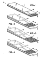
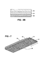
- the present invention generally relates to a photovoltaic cell module and a photovoltaic array. More specifically, the present invention relates to a photovoltaic cell module including a first outermost layer, a photovoltaic cell, and a second outermost layer that has particular properties and that is disposed on the photovoltaic cell sandwiching the photovoltaic cell between the second outermost layer and the first outermost layer. The present invention also relates to a method of forming a photovoltaic cell module.
- Solar or photovoltaic cells are semiconductor devices used to convert light into electricity.
- photovoltaic cells There are two general types of photovoltaic cells, wafers and thin films.
- Wafers are thin sheets of semiconductor material that are typically formed from mechanically sawing the wafer from a single crystal or multicrystal ingot. Alternatively, wafers can be formed from casting.
- Thin film photovoltaic cells usually include continuous layers of semi-conducting materials deposited on a substrate using sputtering or chemical vapor deposition processing techniques.
- the photovoltaic cells are included in photovoltaic cell modules (modules) that also include tie layers, substrates, superstrates, and/or additional materials that provide strength and stability.
- Some modules include glass substrates bonded to glass superstrates using thick tie layers. These types of modules are usually made using processes that are slow and inefficient due to a need to control the dispersion of the tie layers and to minimize leakage of the tie layers from the substrates and superstrates to reduce waste.
- Other types of modules are formed using copious amounts of tie layers that are pushed out from between the substrate and the superstrate and are discarded. In both types of modules, it is difficult to control a thickness of the tie layers because the tie layers can flow across the substrates and superstrates in inconsistent patterns.
- the instant invention provides a photovoltaic cell module and a method of forming the module.
- the photovoltaic cell module includes a first outermost layer having a light transmittance of at least 70 percent as determined by UV/Vis spectrophotometry using ASTM E424-71.
- a photovoltaic cell is disposed on the first outermost layer.
- the module also includes a second outermost layer opposite the first outermost layer.
- the second outermost layer includes a silicone composition.
- the second outermost layer is disposed on the photovoltaic cell and sandwiches the photovoltaic cell between the second outermost layer and the first outermost layer.
- a photovoltaic cell module is formed by a method of this invention.
- the method includes the steps of disposing the photovoltaic cell on the first outermost layer, disposing a silicone composition on the photovoltaic cell, at least partially coating a plurality of fibers with the silicone composition to form a second layer, and compressing the first outermost layer, the photovoltaic cell, and the second layer to form the module.
- the plurality of fibers extends laterally across the second layer to a periphery of the module on both ends of the module. As such, the plurality of fibers is able to resist leakage of the silicone composition from the module during the step of compressing.
- the second (outermost) layer allows the photovoltaic cell to be secured within the module while simultaneously minimizing an amount of the silicone composition that must be used.
- the plurality of fibers of the second (outermost) layer controls dispersion of the silicone composition and a resulting thickness of the module and also minimizes loss or leakage of the silicone composition outside of the module such as during the step of compressing.
- the plurality of fibers, in conjunction with the silicone composition also provides structural strength to the module, decreases flammability of the module, and increases adhesion strength between the photovoltaic cell and the first outermost layer.
- the plurality of fibers and the silicone composition also allow the module to be rigid, semi-rigid, or flexible while maintaining electrical efficiency and structural integrity.
- the plurality of fibers allows for cost effective and repeatable production of the module because of controlled diffusion of the silicone composition, minimization of the amount of silicone composition used, minimized waste, and increased consistency of thickness and size of the module.
- the plurality of fibers and the silicone composition also allow for formation of a module without a supporting layer thereby reducing costs, production complexities, and time needed to form the module.
- Figure 1 is a side cross-sectional view of a first photovoltaic cell module including a first outermost layer, a photovoltaic cell disposed on the first outermost layer, and a second outermost layer disposed on the photovoltaic cell;
- Figure 2 is a side cross-sectional view of a second photovoltaic cell module formed from the method of this invention and including a first outermost layer, a photovoltaic cell disposed on the first outermost layer, a second layer disposed on the photovoltaic cell, and a supporting layer disposed on the second layer as a second outermost layer;
- Figure 3 is a side cross-sectional view of a third photovoltaic cell module including a first outermost layer, a tie layer disposed on, and in direct contact with, the first outermost layer, a photovoltaic cell disposed on, and spaced apart from, the first outermost layer, and a second outermost layer disposed on the photovoltaic cell;
- Figure 4 is a side cross-sectional view of a fourth photovoltaic cell module formed from the method of this invention including a first outermost layer, a tie layer disposed on, and in direct contact with, the first outermost layer, a photovoltaic cell disposed on, and spaced apart from, the first outermost layer, a second layer disposed on the photovoltaic cell, and a supporting layer disposed on, and in direct contact with, the second layer as a second outermost layer;
- Figure 5 is a side cross-sectional view of a second (outermost) layer including a plurality of fibers that are at least partially coated with the silicone composition of this invention
- Figure 6A is a side cross-sectional view of a series of photovoltaic cell modules of Figure 1 that are electrically connected and arranged as a photovoltaic array;
- Figure 6B is a magnified side cross-sectional view of the series of photovoltaic cell modules of Figure 1 that are electrically connected and arranged as a photovoltaic array;
- Figure 7 is a bottom cross-sectional view of the photovoltaic cell module of Figure 1 wherein the plurality of fibers extends laterally (L) across the second layer to a periphery of the photovoltaic cell module on both ends of the module to resist leakage of the silicone composition from the photovoltaic cell module;
- Figure 8 is a side cross-sectional view of a photovoltaic cell module including a first outermost layer, a photovoltaic cell disposed on the first outermost layer, and a second outermost layer disposed on the photovoltaic cell wherein the second outermost layer is free of a plurality of fibers and is formed from a hydrosilylation-curable silicone composition;
- Figure 9 is a side cross-sectional view of a photovoltaic cell module formed from the method of this invention and including a first outermost layer, a photovoltaic cell disposed on the first outermost layer, a second layer disposed on the photovoltaic cell, and a supporting layer disposed on the second layer as a second outermost layer wherein the second layer is free of a plurality of fibers and is formed from a hydrosilylation-curable silicone composition;
- Figure 10 is a side cross-sectional view of a photovoltaic cell module including a first outermost layer, a tie layer disposed on, and in direct contact with, the first outermost layer, a photovoltaic cell disposed on, and spaced apart from, the first outermost layer, and a second outermost layer disposed on the photovoltaic cell wherein the second outermost layer is free of a plurality of fibers and is formed from a hydrosilylation-curable silicone composition; and
- Figure 11 is a side cross-sectional view of a photovoltaic cell module formed from the method of this invention including a first outermost layer, a tie layer disposed on, and in direct contact with, the first outermost layer, a photovoltaic cell disposed on, and spaced apart from, the first outermost layer, a second layer disposed on the photovoltaic cell, and a supporting layer disposed on, and in direct contact with, the second layer as a second outermost layer wherein the second layer is free of a plurality of fibers and is formed from a hydrosilylation-curable silicone composition.
- the present invention provides a photovoltaic cell module 20 (hereinafter referred to as "module") generally shown in Figures 1-4 , 6A/B , and 7-11 and a method of forming the module 20.
- modules 20 convert light energy into electrical energy due to a photovoltaic effect. More specifically, modules 20 perform two primary functions. A first function is photogeneration of charge carriers such as electrons and holes in light absorbing materials. The second function is direction of the charge carriers to a conductive contact to transmit electricity.
- the module 20 of the instant invention can be used in any industry including, but not limited to, automobiles, small electronics, remote area power systems, satellites, space probes, radiotelephones, water pumps, grid-tied electrical systems, batteries, battery chargers, photoelectrochemical applications, polymer solar cell applications, nanocrystal solar cell applications, and dye-sensitized solar cell applications.
- a series of modules 20 are electrically connected and form a photovoltaic array 32, as set forth in Figure 6A .
- Photovoltaic arrays 32 are typically used on rooftops, in rural areas connected to battery backups, and in DC pumps, signal buoys, and the like.
- the photovoltaic array 32 of the instant invention may be planar or non-planar and typically functions as a single electricity producing unit wherein the modules 20 are interconnected in such a way as to generate voltage.
- the module 20 includes a first outermost layer 22 that has a light transmittance of at least 70 percent as determined using UV/Vis spectrophotometry using ASTM E424-71. In one embodiment, the first outermost layer 22 has a light transmittance of at least 80 percent. In an alternative embodiment, the first outermost layer 22 has a light transmittance of at least 90 percent. In still another embodiment, the first outermost layer 22 has a light transmittance of approximately 100 percent.
- the first outermost layer 22 provides protection to a front surface 34 of the module 20, as shown in Figures 1-4 , 6A , and 8-11 .
- the first outermost layer 22 may provide protection to a back surface of the module 20.
- the first outermost layer 22 may be soft and flexible or may be rigid and stiff.
- the first outermost layer 22 may include rigid and stiff segments while simultaneously including soft and flexible segments.
- the first outermost layer 22 includes glass.
- the first outermost layer 22 includes an organic polymer.
- the organic polymer may be selected from the group of, but is not limited to, polyimides, ethylene-vinyl acetate copolymers, and/or organic fluoropolymers including, but not limited to, ethylene tetrafluoroethylene (ETFE), polyethylene terephthalate (PET) alone or at least partially coated with silicon and oxygen based materials (SiO X ), and combinations thereof.
- the first outermost layer 22 may alternatively include silicone, may consist essentially of silicone and not include organic monomers or polymers, or may consist of silicone.
- first outermost layer 22 is not limited to the aforementioned compounds and may include any compound or composition known in the art so long as the first outermost layer 22 has a light transmittance of at least 70 percent using ASTM E424-71.
- the first outermost layer 22 may be load bearing or non load bearing and may be included in any portion of the module 20.
- the first outermost layer 22 may be a "top layer,” also known as a superstrate, or a "bottom layer", also known as a substrate, of the module 20. Bottom layers are typically positioned behind photovoltaic cells 24 and serve as mechanical support.
- the module 20 may include a first outermost layer 22 as a top layer and an additional layer that also has a light transmittance of at least 70 percent using ASTM E424-71 as a bottom layer of the module 20 as a superstrate.
- the additional layer may be the same as or different from the first outermost layer 22.
- the first outermost layer 22 is positioned on a top of the module 20 and in front of a light source. Both the first outermost layer 22 and the additional layer may be used to protect the module 20 from environmental conditions such as rain, show, and heat.
- the first outermost layer 22 has a length and width of 125 mm each. In another embodiment, the first outermost layer 22 has a length and width of 156 mm each.
- the first outermost layer 22, and the instant invention are not limited to these dimensions.
- the module 20 also includes a photovoltaic cell 24.
- the photovoltaic cell 24 is disposed on the first outermost layer 22.
- the photovoltaic cell 24 is disposed directly on the first outermost layer 22, i.e., in direct contact with the first outermost layer 22, as shown in Figures 1, 2 , 6A /B, 8 and 9.
- the photovoltaic cell 24 is spaced apart from the first outermost layer 22 as shown in Figures 3 and 4 and 10 and 11 .
- the photovoltaic cell 24 may be disposed on, and in direct contact with (i.e., directly applied to), the first outermost layer 22 via chemical vapor deposition and/or physical sputtering.
- the photovoltaic cell 24 may be formed apart from the first outermost layer 22 and/or the module 20 and later disposed on the first outermost layer 22.
- the photovoltaic cell 24 is be sandwiched between the second (outermost) layer 26 and a tie layer 30, as described in greater detail below and as shown in Figure 3 and Figure 10 . It is to be appreciated that the terminology “second (outermost)" may apply to both the second outermost layer and the second layer.
- the photovoltaic cell 24 typically has a thickness of from 50 to 250, more typically of from 100 to 225, and most typically of from 175 to 225, micrometers. In one embodiment, the photovoltaic cell 24 has a length and width of 125 mm each. In another embodiment, the photovoltaic cell 24 has a length and width of 156 mm each. Of course it is to be understood that the photovoltaic cell 24, and the instant invention, are not limited to these dimensions.
- the photovoltaic cell 24 may include large-area, single-crystal, single layer p-n junction diodes. These photovoltaic cells 24 are typically made using a diffusion process with silicon wafers. Alternatively, the photovoltaic cell 24 may include thin epitaxial deposits of (silicon) semiconductors on lattice-matched wafers. In this embodiment, the photovoltaic cell 24 may be classified as either space or terrestrial and typically has AMO efficiencies of from 7 to 40%. Further, the photovoltaic cell 24 may include quantum well devices such as quantum dots, quantum ropes, and the like, and also include carbon nanotubes. Without intending to be limited by any particular theory, it is believed that these types of photovoltaic cells 24 can have up to a 45% AMO production efficiency. Still further, the photovoltaic cell 24 may include mixtures of polymers and nano particles that form a single multi-spectrum layer which can be stacked to make multi-spectrum solar cells more efficient and less expensive.
- the photovoltaic cell 24 may include amorphous silicon, monocrystalline silicon, polycrystalline silicon, microcrystalline silicon, nanocrystalline silica, cadmium telluride, copper indium/gallium selenide/sulfide, gallium arsenide, polyphenylene vinylene, copper phthalocyanine, carbon fullerenes, and combinations thereof in ingots, ribbons, thin films, and/or wafers.
- the photovoltaic cell 24 may also include light absorbing dyes such as ruthenium organometallic dyes. Most typically, the photovoltaic cell 24 includes monocrystalline and polycrystalline silicon.
- the photovoltaic cell 24 has a first side and a second side. Typically the first side is opposite the second side. However, the first and second sides may be adjacent each other. A first electrical lead is typically disposed on the first side while a second electrical lead is typically disposed on the second side. One of the first and second electrical leads typically acts as an anode while the other typically acts as a cathode. The first and second electrical leads may be the same or may be different and may include metals, conducting polymers, and combinations thereof. In one embodiment, the first and second electrical leads include tin-silver solder coated copper. In another embodiment, the first and second electrical leads include tin-lead solder coated copper.
- the first and second electrical leads may be disposed on any part of the first and second sides of the photovoltaic cell 24.
- the first and second electrical leads may be of any size and shape and typically are rectangular-shaped and have dimensions of approximately 0.005 to 0.080 inches in length and/or width.
- the first and second electrical leads typically connect the module 20 to additional modules 20 in a photovoltaic array 32, as shown in Figure 6A .
- the modules 20 may be connected in series or in parallel.
- the module 20 also includes the second (outermost) layer 26 disposed on the photovoltaic cell 24. More specifically, the module 22, as set forth in Figures 1, 3 , 6A /B, and 8-11 includes the second (outermost) layer 26.
- the module 22, including the second (outermost) layer 26, has sufficient strength and rigidity without use of any supporting layer 28, described in greater detail below.
- the module 22 may include the second (outermost) layer 26 as the bottom-most layer and not include any additional layers apart from the photovoltaic cell 24 and the first outermost layer 22.
- the module 22 that is formed may include the second layer 26 as an outermost layer or as an interior layer.
- the second (outermost) layer 26 may bind the first outermost layer 22 to the photovoltaic cell 24 and/or at least partially encapsulate the photovoltaic cell 24.
- the second (outermost) layer 26 may be disposed directly on the photovoltaic cell 24, i.e., in direct contact with the photovoltaic cell 24, as shown in Figures 1-4 , 6A/B , and 8-11 , or may be spaced apart from the photovoltaic cell 24.
- the second (outermost) layer 26 is further defined as a controlled bead disposed on the photovoltaic cell 24.
- the second (outermost) layer 26 is a controlled bead of the liquid silicone composition.
- the controlled bead is typically applied in a rectangular shape. However, the controlled bead may be formed in any shape.
- the controlled bead is in contact with an interior portion of the first outermost layer 22, the photovoltaic cell 24, or both the first outermost layer 22 and the photovoltaic cell 24 thereby leaving a space along a perimeter of the first outermost layer 22, the photovoltaic cell 24, or both the first outermost layer 22 and the photovoltaic cell 24 that does not include the second (outermost) layer 26.
- the second (outermost) layer 26 typically has a thickness of from 1 to 50, more typically of from 4 to 40, even more typically of from 3 to 30, and still more typically of from 4 to 15, and most typically of from 4 to 10, mils.
- the second (outermost) layer 26 may be tacky or non-tacky and may be a gel, gum, liquid, paste, resin, or solid.
- the second (outermost) layer 26 is substantially free of entrapped air (bubbles). The terminology "substantially free” means that the second (outermost) layer 26 has no visible air bubbles.
- the second (outermost) layer 26 is formed from a liquid silicone composition, described in detail below, but may be cured or partially cured to be tacky or non-tacky and/or a gel, gum, liquid, paste, resin, or solid.
- partial curing occurs when less than 90 percent of appropriate (i.e., expected) reactive moieties react.
- curing occurs when at least 90 percent of appropriate (i.e., expected) reactive moieties react.
- the second (outermost) layer 26 may include or be free of one or more of polyethylene terephthalate, polyethylene naphthalate, polyvinyl fluoride, and ethylene vinyl acetate.
- the second (outermost) layer 26 includes a plurality of fibers 27, as shown in the Figures. In another embodiment, the second (outermost) layer 26 is free of the plurality of fibers 27, as is described in greater detail below. In Figures 6A /B, the detail for the fibers 27 has been merely omitted for the sake of clarity.
- the second (outermost) layer 26 typically includes at least two, and may include an unlimited number of, individual fibers 27.
- the terminology "fiber” includes continuous filaments and/or discrete lengths of materials that may be natural or synthetic. Natural fibers include, but are not limited to, those produced by plants, animals, and geological processes such as vegetable, wood, animal, and natural mineral fibers.
- Synthetic fibers include, but are not limited to, non-natural mineral fibers such as fiberglass, metallic fibers, carbon fibers, polymer fibers such as polyamide fibers, PET or PBT polyester fibers, phenol-formaldehyde (PF) fibers, polyvinyl alcohol fiber (PVOH) fibers, polyvinyl chloride fiber (PVC) fibers, polyolefins fibers, acrylic fibers, polyacrylonitrile fibers, aromatic polyamide (aramid) fibers, elastomeric fibers, polyurethane fibers, microfibers, and combinations thereof.
- non-natural mineral fibers such as fiberglass, metallic fibers, carbon fibers, polymer fibers such as polyamide fibers, PET or PBT polyester fibers, phenol-formaldehyde (PF) fibers, polyvinyl alcohol fiber (PVOH) fibers, polyvinyl chloride fiber (PVC) fibers, polyolefins fibers, acrylic fibers, polyacrylonitrile fibers, aromatic polyamide (ara
- the plurality of fibers 27 has a high modulus and high tensile strength. In another embodiment, the plurality of fibers 27 has a Young's modulus at 25°C of at least 3 GPa. For example, the plurality of fibers 27 may have a Young's modulus at 25°C of from 3 to 1,000 GPa, alternatively from 3 to 200 GPa, alternatively from 10 to 100 GPa. Moreover, the plurality of fibers 27 may have a tensile strength at 25°C of at least 50 MPa. For example, the plurality of fibers 27 may have a tensile strength at 25°C of from 50 to 10,000 MPa, alternatively from 50 to 1,000 MPa, alternatively from 50 to 500 MPa.
- the individual fibers 27 are typically cylindrical in shape and may have a diameter of from 1 to 100 ⁇ m, alternatively from 1 to 20 ⁇ m, and alternatively form 1 to 10 ⁇ m.
- the plurality of fibers 27 may be heat-treated prior to use to remove organic contaminants.
- the plurality of fibers 27 may be heated in air at an elevated temperature, for example, 575 °C, for a suitable period of time, for example 2 h.
- the plurality of fibers 27 is further defined as a mat or roving. In another embodiment, the plurality of fibers 27 is further defined as a textile.
- the textile may be woven or non-woven or may include both woven and non-woven segments. In one embodiment, the textile is woven and is selected from the group of fiberglass, polyester, polyethylene, polypropylene, nylon, and combinations thereof. In another embodiment, the textile is non-woven and is selected from the group of fiberglass, polyester, polyethylene, polypropylene, nylon, and combinations thereof. In a further embodiment, the textile is non-woven fiberglass and is commercially available from Crane Nonwovens of Dalton, MA. Alternatively, the textile may be non-woven polyester commercially available from Crane Nonwovens.
- the textile may be non-woven and include polypropylene or polyethylene terephthalate.
- the textile is not limited to aforementioned types of woven and non-woven textiles and may include any woven or non-woven textile known in the art.
- the second (outermost) layer 26 includes more than one textile, e.g. two, three, or more individual textiles.
- woven textiles are typically cloths that are formed by weaving and that stretch in bias directions.
- non-woven textiles are neither woven nor knit and are typically manufactured by putting individual fibers 27 together in the form of a sheet or web, and then binding them either mechanically, with an adhesive, or thermally by melting a binder onto the textile.
- Non-woven textiles may include staple non-woven textiles and spunlaid non-woven textiles.
- Staple non-woven textiles are typically made by spinning fibers that are spread in a uniform web and then bonded by using either resin or heat.
- Spunlaid non-woven textiles are typically made in one continuous process by spinning fibers directly disposed into a web. The spunlaid process can be combined with a meltblowing process to form a SMS (spun-melt-spun) non-woven textile.
- Non-woven textiles may also include films and fibrillates and can be formed using serration or vacuum-forming to form patterned holes.
- Fiberglass non-woven textiles typically are one of two types including wet laid mats having wet-chopped, denier fibers having 6 to 20 micrometer diameters or flame attenuated mats having discontinuous denier fibers having 0.1 to 6 micrometer diameters.
- the plurality of fibers 27 is at least partially coated with a silicone composition.
- at least 50, 75, or 95 percent of a total surface area of the plurality of fibers 27 is coated with the silicone composition.
- approximately 100 percent of a total surface area of the plurality of fibers 27 is coated with the silicone composition.
- Figure 5 illustrates that at least 50 percent of a total surface area of the plurality of fibers 27 may be coated with the silicone composition.
- the terminology “coated” refers to covering at least part of the surface area of the plurality of fibers 27.
- the silicone composition exudes through portions of the plurality of fibers 27 (e.g. the textile) such as pores.
- the plurality of fibers 27 is further defined as a textile and defines voids through which the silicone composition may exude.
- the plurality of fibers 27 is further defined as being impregnated with the silicone composition. The silicone composition may impregnate some or all of the plurality of fibers 27.
- the silicone composition coats an exterior (surface area) of the plurality of fibers 27 and is also disposed throughout some or all of the voids defined by the plurality of fibers 27.
- the silicone composition may exude through some voids and not through others.
- the plurality of fibers 27 is saturated with the silicone composition.
- the plurality of fibers 27 is not saturated with the silicone composition. It is also contemplated that the silicone composition may encapsulate the plurality of fibers 27 in whole or in part. The silicone composition may also encapsulate the photovoltaic cell 24 in whole or in part.
- the surface area of the plurality of fibers 27 may be partially coated using any method known in the art including, but not limited to, spraying, dipping, rolling, brushing, and combinations thereof.
- the plurality of fibers 27 is placed into the silicone composition.
- the silicone composition typically coats at least a part of the total surface area of the plurality of fibers 27 in a thickness 1 to 50, more typically of from 3 to 30, and most typically of from 4 to 15, mils. Of course, the invention is not limited to these thicknesses.
- the silicone composition may be any known in the art and may include, but is not limited to, silanes, siloxanes, silazanes, silylenes, silyl radicals or ions, elemental silicon, silenes, silanols, polymers thereof, and combinations thereof.
- the silicone composition may be cured, partially cured, or completely cured by any mechanism known in the art including, but not limited to, free radical reactions, hydrosilylation reactions, condensation or addition reactions, heat curing, UV curing, and combinations thereof.
- the silicone composition of this invention is further defined as hydrosilylation-curable.
- hydrosilylation cure silicone chemistry is focused on below. However, the invention is not limited to hydrosilylation cure silicone chemistry, as introduced above.
- the silicone composition includes an organosilicon compound, an organohydrogensilicon compound, and a hydrosilylation catalyst.
- the organosilicon compound typically has at least one unsaturated moiety per molecule and may include a single organosilicon compound, two organosilicon compounds, or a plurality of organosilicon compounds. In various embodiments, the organosilicon compound has two, three, or multiple unsaturated moieties per molecule.
- the organosilicon compound includes an alkenyl siloxane wherein an alkenyl group is pending from a siloxane group. The alkenyl group may be located at any interval and/or location in the siloxane group.
- the alkenyl group may be terminal, pendant, or if the organosilicon compound includes more than one alkenyl group, the alkenyl groups may be both terminal and pendant.
- the organosilicon compound is terminated with a siloxane that is itself alkenyl terminated.
- the alkenyl siloxane is an alkenyl-terminated siloxane, i.e., the alkenyl group may be located at one or more terminal ends of the siloxane group.
- the alkenyl siloxane may be an alkenyl-pendent siloxane.
- the alkenyl-pendent siloxane typically includes at least one alkenyl group pending from any location along the siloxane group other than at one of the terminal ends of the siloxane group.
- the alkenyl -terminated or -pendant siloxane may be linear, branched, cyclic, or any combination thereof.
- the alkenyl-terminated siloxane may include more than one alkenyl group. The more than one alkenyl group may be bonded to the same atom within the siloxane or, alternatively, may be bonded to different atoms in the siloxane. It is also contemplated that the at least one unsaturated moiety may include alkynyl groups which may be substituted for alkenyl groups, where chemically appropriate.
- the organosilicon compound has silicon-bonded alkenyl groups and typically is a copolymer including R 2 SiO 3/2 units, i.e., T units, and/or SiO 4/2 units, i.e., Q units, in combination with R 1 R 2 2 SiO 1/2 units, i.e., M units, and/or R 2 2 SiO 2/2 units, i.e., D units, wherein R 1 is a C 1 to C 10 hydrocarbyl group or a C 1 to C 10 halogen-substituted hydrocarbyl group, both free of aliphatic unsaturation, and R 2 is an alkenyl group.
- R 1 is a C 1 to C 10 hydrocarbyl group or a C 1 to C 10 halogen-substituted hydrocarbyl group, both free of aliphatic unsaturation
- R 2 is an alkenyl group.
- the organosilicon compound can be further defined as a DT resin, an MT resin, an MDT resin, a DTQ resin, an MTQ resin, an MDTQ resin, a DQ resin, an MQ resin, a DTQ resin, an MTQ resin, or an MDQ resin, so long as it has at least one unsaturated moiety per molecule.
- the C 1 to C 10 hydrocarbyl group and C 1 to C 10 halogen-substituted hydrocarbyl group represented by R 1 more typically have from 1 to 6 carbon atoms.
- Acyclic hydrocarbyl and halogen-substituted hydrocarbyl groups containing at least 3 carbon atoms can have a branched or unbranched structure.
- hydrocarbyl groups represented by R 1 include, but are not limited to, alkyl groups, such as methyl, ethyl, propyl, 1-methylethyl, butyl, 1-methylpropyl, 2-methylpropyl, 1,1-dimethylethyl, pentyl, 1-methylbutyl, 1-ethylpropyl, 2-methylbutyl, 3-methylbutyl, 1,2-dimethylpropyl, 2,2-dimethylpropyl, hexyl, heptyl, octyl, nonyl, and decyl, cycloalkyl groups, such as cyclopentyl, cyclohexyl, and methylcyclohexyl, aryl groups, such as phenyl and naphthyl, alkaryl groups, such as tolyl and xylyl, and aralkyl groups, such as benzyl and phenethyl.
- alkyl groups such as methyl,
- halogen-substituted hydrocarbyl groups represented by R 1 include, but are not limited to, 3,3,3-trifluoropropyl, 3-chloropropyl, chlorophenyl, dichlorophenyl, 2,2,2-trifluoroethyl, 2,2,3,3-tetrafluoropropyl, and 2,2,3,3,4,4,5,5-octafluoropentyl.
- the alkenyl groups represented by R 2 typically have from 2 to 10 carbon atoms, alternatively from 2 to 6 carbon atoms, and are exemplified by, but are not limited to, vinyl, allyl, methallyl, butenyl, hexenyl, octenyl, decenyl, cycohexenyl, styryl, and the like.
- the organosilicon compound is further defined as having the formula: (R 1 R 2 2 SiO 1/2 ) w (R 2 2 SiO 2/2 ) x (R 2 SiO 3/2 ) y (SiO 4/2 ) z (I) wherein R 1 and R 2 are as described and exemplified above and w, x, y, and z are mole fractions.
- the organosilicon compound represented by formula (I) has an average of at least two silicon-bonded alkenyl groups per molecule. More specifically, the subscript w typically has a value of from 0 to 0.9, alternatively from 0.02 to 0.75, alternatively from 0.05 to 0.3.
- the subscript x typically has a value of from 0 to 0.9, alternatively from 0 to 0.45, alternatively from 0 to 0.25.
- the subscript y typically has a value of from 0 to 0.99, alternatively from 0.25 to 0.8, alternatively from 0.5 to 0.8.
- the subscript z typically has a value of from 0 to 0.85, alternatively from 0 to 0.25, alternatively from 0 to 0.15.
- the ratio y+z/(w+x+y+z) is typically from 0.1 to 0.99, alternatively from 0.5 to 0.95, alternatively from 0.65 to 0.9.
- the ratio w+x/(w+x+y+z) is typically from 0.01 to 0.90, alternatively from 0.05 to 0.5, alternatively from 0.1 to 0.35.
- organosilicon compounds represented by formula (I) set forth above include, but are not limited to, resins having the following formulae: (Vi 2 MeSiO 1 ⁇ 2 ) 0.25 (PhSiO 3/2 ) 0.75 , (ViMe 2 SiO 1 ⁇ 2 ) 0.25 (PhSiO 3/2 ) 0.75 , (ViMe 2 SiO 1 ⁇ 2 ) 0.25 (MeSiO 3/2 ) 0.25 (PhSiO 3/2 ) 0.50 , (ViMe 2 SiO 1 ⁇ 2 ) 0.15 (PhSiO 3/2 ) 0.75 (SiO 4/2 ) 0.1 , and (Vi 2 MeSiO 1/2 ) 0.15 (ViMe 2 SiO 1/2 ) 0.1 (PhSiO 3/2 ) 0.75 , wherein Me is methyl, Vi is vinyl, Ph is phenyl, and the numerical subscripts outside the parenthesis denote mole fractions corresponding to either
- the organosilicon compound represented by formula (I) typically has a number-average molecular weight (M n ) of from 500 to 50,000, alternatively from 500 to 10,000, alternatively 1,000 to 3,000, g/mol, where the molecular weight is determined by gel permeation chromatography employing a low angle laser light scattering detector, or a refractive index detector and silicone resin (MQ) standards.
- M n number-average molecular weight
- the viscosity of the organosilicon compound represented by formula (I) at 25°C may be from 0.01 to 100,000 Pa.s, alternatively from 0.1 to 10,000 Pa.s, alternatively from 1 to 100 Pa ⁇ s.
- the organosilicon compound represented by formula (I) typically includes less than 10% (w/w), alternatively less than 5% (w/w), alternatively less than 2% (w/w), of silicon-bonded hydroxy groups, as determined by 29 Si NMR.
- the organosilicon compound is further defined as a dialkylvinylsiloxy-terminated dialkyl siloxane. In another embodiment, the organosilicon compound is further defined as a dialkylalkenylsiloxy-terminated dialkylsiloxane. Non-limiting examples of the organosilicon compound include dimethylvinylsiloxy-terminated dimethylsiloxane, dimethylvinylsiloxy-terminated dimethyl siloxane, methylvinyl siloxane, and combinations thereof. In yet another embodiment, the organosilicon compound is further defined as dimethylvinylsiloxy-pendent dimethylsiloxane.
- the organosilicon compound may be further defined as an alkenyldialkylsilyl end-blocked polydialkylsiloxane.
- the organosilicon compound is further defined as vinyldimethylsilyl end-blocked polydimethylsiloxane.
- the silicone composition also typically includes the organohydrogensilicon compound having at least one silicon-bonded hydrogen atom per molecule.
- the organohydrogensilicon compound may include a single organohydrogensilicon compound, two organohydrogensilicon compounds, or a plurality of organohydrogensilicon compounds.
- the organohydrogensilicon compound typically has an average of at least two silicon-bonded hydrogen atoms per molecule, and alternatively at least three silicon-bonded hydrogen atoms per molecule.
- the organohydrogensilicon compound may be further defined as an organohydrogensilane, an organohydrogensiloxane, or a combination thereof.
- the structure of the organohydrogensilicon compound can be linear, branched, cyclic, or resinous.
- the silicon-bonded hydrogen atoms can be located at terminal, pendant, or at both terminal and pendant positions.
- Cyclosilanes and cyclosiloxanes typically have from 3 to 12 silicon atoms, alternatively from 3 to 10 silicon atoms, alternatively from 3 to 4 silicon atoms.
- the organohydrogensilane can be a monosilane, disilane, trisilane, or polysilane.
- suitable organohydrogensilanes include diphenylsilane, 2-chloroethylsilane, bis[(p-dimethylsilyl)phenyl]ether, 1,4-dimethyldisilylethane, 1,3,5-tris(dimethylsilyl)benzene, 1,3,5-trimethyl-1,3,5-trisilane, poly(methylsilylene)phenylene, and poly(methylsilylene)methylene.
- the organohydrogensilane can also have the formula: HR 1 2 Si-R 3 -SiR 1 2 H (II) wherein R 1 is as defined and exemplified above and R 3 is a hydrocarbylene group free of aliphatic unsaturation having a formula selected from the following structures: wherein g is from 1 to 6.
- organohydrogensilanes of the above formula (II) wherein R 1 and R 3 are as described and exemplified above include, but are not limited to, organohydrogensilanes having a formula selected from the following structures: , and
- the organohydrogensiloxane can be a disiloxane, trisiloxane, or polysiloxane.
- suitable organohydrogensiloxanes include 1,1,3,3-tetramethyldisiloxane, 1,1,3,3-tetraphenyldisiloxane, phenyltris(dimethylsiloxy)silane, 1,3,5-trimethylcyclotrisiloxane, a trimethylsiloxy-terminated poly(methylhydrogensiloxane), a trimethylsiloxy-terminated poly(dimethylsiloxane/methylhydrogensiloxane), a dimethylhydrogensiloxy-terminated poly(methylhydrogensiloxane), and a resin including HMe 2 SiO 1 ⁇ 2 units, Me 3 SiO 1/2 units, and SiO 4/2 units, wherein Me is methyl.
- the organohydrogensiloxane may be further defined as an organohydrogenpolysiloxane resin, so long as the resin includes at least one silicon-bonded hydrogen atom per molecule.
- the organohydrogenpolysiloxane resin may be a copolymer including R 4 SiO 3/2 units, i.e., T units, and/or SiO 4/2 units, i.e., Q units, in combination with R 1 R 4 2 SiO 1/2 units, i.e., M units, and/or R 4 2 SiO 2/2 units, i.e., D units, wherein R 1 is as described and exemplified above.
- the organohydrogenpolysiloxane resin can be a DT resin, an MT resin, an MDT resin, a DTQ resin, an MTQ resin, an MDTQ resin, a DQ resin, an MQ resin, a DTQ resin, an MTQ resin, or an MDQ resin.
- the group represented by R 4 is typically an organosilylalkyl group having at least one silicon-bonded hydrogen atom.
- organosilylalkyl groups represented by R 4 include, but are not limited to, groups having a formula selected from the following structures: -CH 2 CH 2 SiMe 2 H, -CH 2 CH 2 SiMe 2 C n H 2n SiMe 2 H, -CH 2 CH 2 SiMe 2 C n H 2n SiMePhH, -CH 2 CH 2 SiMePhH, -CH 2 CH 2 SiPh 2 H, -CH 2 CH 2 SiMePhC n H 2n SiPh 2 H, -CH 2 CH 2 SiMePhC n H 2n SiMe 2 H, -CH 2 CH 2 SiMePhOSiMePhH, and -CH 2 CH 2 SiMePhOSiPh(OSiMePhH) 2 , wherein Me is methyl, Ph is phenyl, and the
- the organohydrogenpolysiloxane resin has the formula: (R 1 R 4 2 SiO 1 ⁇ 2 ) w (R 4 2 SiO 2/2 ) x (R 4 SiO 3/2 ) y (SiO 4/2 ) z wherein R 1 , R 4 ,w, x, y, and z are each as defined and exemplified above.
- organohydrogenpolysiloxane resins represented by the above formula include, but are not limited to, resins having the following formulae: ((HMe 2 SiC 6 H 4 SiMe 2 CH 2 CH 2 ) 2 MeSiO 1/2 ) 0.12 (PhSiO 3/2 ) 0.88 , ((HMe 2 SiC 6 H 4 SiMe 2 CH 2 CH 2 ) 2 MeSiO 1/2 ) 0.17 (PhSiO 3/2 ) 0.83 , ((HMe 2 SiC 6 H 4 SiMe 2 CH 2 CH 2 ) 2 MeSiO 1/2 ) 0.17 (MeSiO 3/2 ) 0.17 (PhSiO 3/2 ) 0.66 , ((HMe 2 SiC 6 H 4 SiMe 2 CH 2 CH 2 ) 2 MeSiO 1/2 ) 0.15 (PhSiO 3/2 ) 0.75 (SiO 4/2 ) 0.10 , and ((HMe 2 SiC 6 H 4 SiMe 2 CH 2 CH 2 CH 2
- the organohydrogensilicon compound may have a molecular weight less than 1,000, alternatively less than 750, alternatively less than 500, g/mol.
- the organohydrogensilicon compound can be a single organohydrogensilicon compound or a mixture comprising two or more different organohydrogensilicon compound, each as described above.
- the organohydrogensilicon compound can be a single organohydrogensilane, a mixture of two different organohydrogensilanes, a single organohydrogensiloxane, a mixture of two different organohydrogensiloxanes, or a mixture of an organohydrogensilane and an organohydrogensiloxane, so long as the organohydrogensilicon compound has at least one silicon-bonded hydrogen atom per molecule.
- the organohydrogensilicon compound is further defined as a dimethylhydrogensilyl terminated polydimethylsiloxane.
- the organohydrogensilicon compound may also be further defined as a trialkylsilyl terminated polydialkylsiloxane - alkylhydrogensiloxane co-polymer. In one embodiment, the organohydrogensilicon compound is further defined as a trimethylsilyl terminated polydimethylsiloxane - methylhydrogensiloxane co-polymer. In one embodiment, the organohydrogensilicon compound is further defined as a mixture of a dialkylhydrogensilyl terminated polydialkylsiloxane and a trialkylsilyl terminated polydialkylsiloxane - alkylhydrogensiloxane co-polymer.
- dialkylhydrogensilyl terminated polydialkylsiloxane of this embodiment may be further defined as dimethylhydrogensilyl terminated polydimethylsiloxane and the trialkylsilyl terminated polydialkylsiloxane - alkylhydrogensiloxane co-polymer of this embodiment may be further defined as a trimethylsilyl terminated polydimethylsiloxane - methylhydrogensiloxane co-polymer.
- the silicone composition also typically includes a hydrosilylation catalyst used to accelerate a hydrosilylation reaction between the organosilicon compound and the organohydrogensilicon compound.
- the hydrosilylation catalyst can be any of the well-known hydrosilylation catalysts comprising a platinum group metal (i.e., platinum, rhodium, ruthenium, palladium, osmium and iridium) or a compound containing a platinum group metal.
- the platinum group metal is platinum, based on its high activity in hydrosilylation reactions.
- hydrosilylation catalysts suitable for use include the complexes of chloroplatinic acid and certain vinyl-containing organosiloxanes disclosed by Willing in U.S. Pat. No. 3,419,593 , the portions of which address hydrosilylation catalysts are hereby incorporated by reference.
- a catalyst of this type is the reaction product of chloroplatinic acid and 1,3-diethenyl-1,1,3,3-tetramethyldisiloxane.
- the hydrosilylation catalyst can also be a supported hydrosilylation catalyst comprising a solid support having a platinum group metal on the surface thereof.
- a supported catalyst can be conveniently separated from the silicone composition by filtration.
- supported catalysts include, but are not limited to, platinum on carbon, palladium on carbon, ruthenium on carbon, rhodium on carbon, platinum on silica, palladium on silica, platinum on alumina, palladium on alumina, and ruthenium on alumina.
- the hydrosilylation catalyst may be a microencapsulated platinum group metal-containing catalyst comprising a platinum group metal encapsulated in a thermoplastic resin.
- Silicone compositions including microencapsulated hydrosilylation catalysts are stable for extended periods of time, typically several months or longer, under ambient conditions, yet cure relatively rapidly at temperatures above the melting or softening point of the thermoplastic resin(s).
- Microencapsulated hydrosilylation catalysts and methods of preparing them are well known in the art, as exemplified in U.S. Pat. No. 4,766,176 and the references cited therein, and U.S. Pat. No. 5,017,654 .
- the hydrosilylation catalyst of this invention can be a single catalyst or a mixture comprising two or more different catalysts that differ in at least one property, such as structure, form, platinum group metal, complexing ligand, and thermoplastic resin.
- the hydrosilylation catalyst includes at least one photoactivated hydrosilylation catalyst.
- the photoactivated hydrosilylation catalyst can be any hydrosilylation catalyst capable of catalyzing the hydrosilylation of the organosilicon compound and the organohydrogensilicon compound upon exposure to radiation having a wavelength of from 150 to 800 nm.
- the photoactivated hydrosilylation catalyst can be any of the well-known hydrosilylation catalysts comprising a platinum group metal or a compound containing a platinum group metal.
- the platinum group metals include platinum, rhodium, ruthenium, palladium, osmium, and iridium. Typically, the platinum group metal is platinum, based on its high activity in hydrosilylation reactions.
- photoactivated hydrosilylation catalysts suitable for purposes of the present invention include, but are not limited to, platinum(II) ⁇ -diketonate complexes such as platinum(II) bis(2,4-pentanedionate), platinum(II) bis(2,4-hexanedionate), platinum(II) bis(2,4-heptanedionate), platinum(II) bis(1-phenyl-1,3-butanedionate, platinum(II) bis(1,3-diphenyl-1,3-propanedionate), platinum(II) bis (1,1,1,5,5,5-hexafluoro-2,4-pentanedioate); ( ⁇ -cyclopentadienyl)trialkylplatinum complexes, such as (Cp)trimethylplatinum, (Cp)ethyldimethylplatinum, (Cp)triethylplatinum, (chloro-Cp)trimethylplatin
- the photoactivated hydrosilylation catalyst is a Pt(II) ⁇ -diketonate complex and more typically the catalyst is platinum(II) bis(2,4-pentanedioate).
- the hydrosilylation catalyst can be a single photoactivated hydrosilylation catalyst or a mixture comprising two or more different photoactivated hydrosilylation catalysts.
- Methods of preparing photoactivated hydrosilylation catalysts are well known in the art. For example, methods of preparing platinum(II) ⁇ -diketonates are reported by Guo et al. (Chemistry of Materials, 1998, 10, 531-536 ). Methods of preparing ( ⁇ -cyclopentadienyl)-trialkylplatinum complexes are disclosed in U.S. Patent No. 4,510,094 . Methods of preparing triazene oxide-transition metal complexes are disclosed in U.S. Patent No. 5,496,961 . Methods of preparing ( ⁇ -diolefin)( ⁇ -aryl)platinum complexes are taught in U.S. Patent No. 4,530,879 .
- the concentration of hydrosilylation catalyst is sufficient to catalyze the hydrosilylation of the organosilicon compound and the organohydrogensilicon compound.
- the concentration of the hydrosilylation catalyst is sufficient to provide from 0.1 to 1000 ppm of a platinum group metal, alternatively from 1 to 500 ppm of a platinum group metal, alternatively from 3 to 150 ppm of a platinum group metal, and alternatively from 1 to 25 ppm of a platinum group metal, based on the combined weight of the organosilicon compound and the organohydrogensilicon compound.
- One particularly suitable catalyst includes 1,3-diethenyl-1,1,3,3-tetramethyldisiloxane platinum complexes.
- the catalysts may be included in amounts as determined by one of skill in the art.
- the catalyst is included in the silicone composition in an amount of from 0.05 to 0.30 parts by weight per 100 parts by weight of the silicone composition.
- the silicone composition also typically includes a ratio of silicon-bonded hydrogen atoms per molecule of the organohydrogensilicon compound to unsaturated moieties per molecule of the organosilicon compound of from 0.05 to 100.
- the ratio is from 0.1 to 100, 0.05 to 20, 0.05 to 0.7, 0.1 to 0.8, 0.1 to 0.6, 0.5 to 2, 1.5 to 5, 1.75 to 3, 2 to 2.5, and from 0.95 to 1.05.
- there is a stoichiometric excess of silicon bonded hydrogen atoms to unsaturated moieties which may enhance adhesion between the first outermost layer 22 and the second (outermost) layer 26 or a tie layer 30, described in greater detail below.
- the above referenced ratios do not limit this invention so long as the ratio is between 0.05 to 100.
- the second (outermost) layer 26 may be free of the plurality of fibers 27 or may include the plurality of fibers 27.
- the silicone composition used to form the second (outermost) layer 26 is further defined as a hydrosilylation-curable silicone composition which may coat the plurality of fibers 27, as described above.
- this hydrosilylation-curable silicone composition is liquid, i.e., flows at room temperature.
- the hydrosilylation-curable silicone composition may include a filler or be free of the filler.
- the hydrosilylation-curable silicone composition may include both the plurality of fibers 27 and the filler.
- the hydrosilylation-curable silicone composition includes a linear organosilicon compound having two terminal unsaturated moieties per molecule, a branched organosilicon compound having two terminal unsaturated moieties per molecule and at least one pendant unsaturated moiety per molecule, and an organohydrogensilicon compound having at least one silicon-bonded hydrogen atom per molecule.
- the organohydrogensilicon compound has at least two silicon-bonded hydrogen atoms per molecule.
- the organohydrogensilicon compound has at least three silicon-bonded hydrogen atoms per molecule.
- the hydrosilylation-curable silicone composition also typically includes the filler, introduced above, and a hydrosilylation catalyst used to accelerate a hydrosilylation reaction between the linear organosilicon compound, the branched organosilicon compound, and the organohydrogensilicon compound.
- a hydrosilylation catalyst used to accelerate a hydrosilylation reaction between the linear organosilicon compound, the branched organosilicon compound, and the organohydrogensilicon compound.
- hydrosilylation catalysts that can be utilized in this embodiment are described above.
- the linear organosilicon compound is present in an amount of from 80 to 95 parts by weight and the branched organosilicon compound is present in an amount of from 5 to 20 as parts by weight, per 100 parts by weight of a sum of the linear organosilicon compound and the branched organosilicon compound.
- the linear organosilicon compound is present in an amount of from 85 to 95, from 86 to 94, from 88 to 90, from 90 to 95, or from 92 to 94, or of about 80, 86, 90, or 93, parts by weight, per 100 parts by weight of a sum of the linear organosilicon compound and the branched organosilicon compound.
- the branched organosilicon compound is present in an amount of from 5 to 15, from 7 to 10, from 7 to 14, from 10 to 20, or of about 7, 10, 14, or 20, parts by weight, per 100 parts by weight of a sum of the linear organosilicon compound and the branched organosilicon compound. It is to be understood that the linear and/or branched organosilicon compounds may each be independently utilized in any amount or range of amounts within those ranges described above.
- a ratio of silicon-bonded hydrogen atoms per molecule of the organohydrogensilicon compound to a sum of unsaturated moieties per molecule of the linear organosilicon compound and the branched organosilicon compound is from 1 to 1.7, typically from 1,1 to 1.6 or from 1.1 to 1.2. In various embodiments, the ratio is from 1.5 to 1.55.
- the hydrosilylation-curable silicone composition may include a first portion and a second portion when used.
- the linear organosilicon compound, the branched organosilicon compound, and the organohydrogensilicon compound may be present in the first portion, the second portion, or in both the first and second portions.
- the linear organosilicon compound, the branched organosilicon compound, and the organohydrogensilicon compound are not all present in one portion due to a potential to prematurely react.
- the organosilicon compound, the branched organosilicon compound, and the organohydrogensilicon compound arc all present in one portion but arc not present with a hydrosilylation catalyst.
- the linear and branched organosilicon compounds are present in the first portion and the organohydrogensilicon compound and the hydrosilylation catalyst are present in the second portion.
- the linear organosilicon compound and/or the branched organosilicon compound are present in both the first and second portions while the hydrosilylation catalyst is present in the first portion and the organohydrogensilicon compound is present in the second portion.
- any cross-linker or chain extender is present in the second portion without the catalyst.
- the first and second portions have varying viscosities of from 200 to 15,000 cps at 25°C determined according to ASTM D4287.
- the first and second portions have approximate viscosities as follows: 289, 289, 1449, 2000, 2064, 3440, 4950, 5344, 8,194, 11.212, 12,680, and 14,129, cps at 25°C determined according to ASTM D4287.
- the linear organosilicon compound may be any of the compounds described above or may be different so long as the linear organosilicon compound has two terminal unsaturated moieties per molecule. Typically, the linear organosilicon compound has exactly two terminal unsaturated moieties per molecule. The linear organosilicon compound does not have pendant unsaturated moieties.
- the linear organosilicon compound is further defined as a vinyl end-blocked polydialkylsiloxane, e.g. a vinyl end-blocked polydimethylsiloxane that has two terminal vinyl groups.
- the linear organosilicon compound has an average degree of polymerization (DP) of from 150 to 900.
- the linear organosilicon compound has the following physical properties ⁇ 1%, ⁇ 3%, ⁇ 5%, ⁇ 10%, ⁇ 15%, ⁇ 20%, or ⁇ 25%. It is also contemplated that the linear organosilicon compound may have other physical properties not set forth below.
- the hydrosilylation-curable silicone composition may include more than one linear organosilicon compound that is described above. Additional linear organosilicon compounds that are contemplated for use in this invention are described in U.S. Pat. No. 5,574,073 , which is expressly incorporated herein by reference.
- the branched organosilicon compound may also be any of the compounds described above or may be different so long as the branched organosilicon compound has two terminal unsaturated moieties per molecule and at least one pendant unsaturated moiety per molecule.
- the branched organosilicon compound is further defined as a vinyl end-blocked polydialkylsiloxane having at least one vinyl pendant group, e.g. a vinyl end-blocked polydimethylsiloxane having two terminal vinyl groups and at least one vinyl pendant group.
- the branched organosilicon compound has an average degree of polymerization (DP) of from 100 to 800, a weight average molecular weight of from 8,000 to 60,000, a viscosity of from 200 to 30,000 cps at 25°C determined according to ASTM D4287, and a weight percent of vinyl groups of from 0.1 to 10.
- the branched organosilicon compound has an average degree of polymerization (DP) of about 620, a weight average molecular weight of about 46,000 g/mol, a viscosity of about 15,000 cps at 25°C determined according to ASTM D4287, and a weight percent of vinyl groups of about 7.7.
- hydrosilylation-curable silicone composition may include more than one branched organosilicon compound that is described above. Additional branched organosilicon compound that are contemplated for use in this invention are described in U.S. Pat. No. 5,574,073 , which is expressly incorporated herein by reference.
- sicone composition and "hydrosilylation-curable silicone composition,” when used herein, are interchangeable so long as the hydrosilylation-curable silicone composition remains as described above. Said differently, this terminology is interchangeable so long as the hydrosilylation-curable silicone composition includes a linear organosilicon compound having two terminal unsaturated moieties per molecule, a branched organosilicon compound having two terminal unsaturated moieties per molecule and at least one pendant unsaturated moiety per molecule, and an organohydrogensilicon compound having at least one silicon-bonded hydrogen atom per molecule.
- the silicone composition may also include a silicone rubber having a formula selected from the group of (a) R 1 R 2 2 SiO(R 2 2 SiO) a SiR 2 2 R 1 and (b) R 5 R 1 2 SiO(R 1 R 5 SiO) b SiR 1 2 R 5 ; wherein R 1 and R 2 are as defined and exemplified above, R 5 is R 1 or -H, subscripts a and b each have a value of from 1 to 4, alternatively from 2 to 4, alternatively from 2 to 3, and w, x, y, and z are also as defined and exemplified above.
- silicone rubbers suitable for use as silicone rubber (a) include, but are not limited to, silicone rubbers having the following formulae: ViMe 2 SiO(Me 2 SiO) a SiMe 2 Vi, ViMe 2 SiO(Ph 2 SiO) a SiMe 2 Vi, and ViMe 2 SiO(PhMeSiO) a SiMe 2 Vi wherein Me is methyl, Ph is phenyl, Vi is vinyl, and the subscript has a value of from 1 to 4.
- Silicone rubber (a) can be a single silicone rubber or a mixture comprising two or more different silicone rubbers that each satisfy the formula for (a).
- silicone rubbers suitable for use as silicone rubber (b) include, but are not limited to, silicone rubbers having the following formulae: HMe 2 SiO(Me 2 SiO) b SiMe 2 H, HMe 2 SiO(Ph 2 SiO) b SiMe 2 H, HMe 2 SiO(PhMeSiO) b SiMe 2 H, and HMe 2 SiO(Ph 2 SiO) 2 (Me 2 SiO) 2 SiMe 2 H wherein Me is methyl, Ph is phenyl, and the subscript b has a value of from 1 to 4.
- Component (b) can be a single silicone rubber or a mixture comprising two or more different silicone rubbers that each satisfy the formula for (b).
- the silicone composition includes a rubber-modified silicone resin prepared by reacting the organosilicon compound and at least one silicone rubber (b) selected from rubbers having the following formulae: R 5 R 1 2 SiO(R 1 R 5 SiO) c SiR 1 2 R 5 , and R 1 R 2 2 SiO(R 2 2 SiO) d SiR 2 2 R 1 , wherein R 1 and R 5 are as defined and exemplified above and c and d each have a value of from 4 to 1000, alternatively from 10 to 500, alternatively from 10 to 50, in the presence of the hydrosilylation catalyst and, optionally, an organic solvent, provided that the reaction product of the organosilicon compound and the silicone rubber (b) has at least one unsaturated moiety per molecule.
- silicone rubber selected from rubbers having the following formulae: R 5 R 1 2 SiO(R 1 R 5 SiO) c SiR 1 2 R 5 , and R 1 R 2 2 SiO(R 2 2 SiO) d SiR 2 2 R 1 ,
- the silicone composition includes from 45 to 90 parts by weight of a dimethylvinylsiloxy-terminated dimethylsiloxane, from 0.5 to 2 parts by weight of an alkoxysilane, 0.5 to 2 parts by weight of a methacryloxypropyltrimethoxysilane, from 0.01 to 0.2 parts by weight of tetramethyltetravinycyclotetrasiloxane, from 2 to 10 parts by weight of a hydrogen terminated dimethylsiloxane, from 0.2 to 1 parts by weight of dimethylmethylhydrogensiloxane, and from 0.01 to 0.1 parts by weight of 1,3-diethenyl-1,1,3,3-tetramethyldisiloxane platinum complexes.
- a dimethylvinylsiloxy-terminated dimethylsiloxane from 0.5 to 2 parts by weight of an alkoxysilane, 0.5 to 2 parts by weight of a methacryloxypropyltrimethoxysilane, from 0.01 to
- the silicone composition includes from 45 to 90 parts by weight of a dimethylvinylsiloxy-terminated dimethylsiloxanes, from 0.5 to 2 parts by weight of an alkoxysilane, 0.5 to 2 parts by weight of a methacryloxypropyltrimethoxysilane, from 0.01 to 0.2 parts by weight of tetramethyltetravinycyclotetrasiloxane, from 2 to 10 parts by weight of a hydrogen terminated dimethylsiloxane, from 0.2 to 1 parts by weight of dimethylmethylhydrogensiloxane, from 20 to 60 parts by weight of quartz, and from 0.01 to 0.1 parts by weight of 1,3-diethenyl-1,1,3,3-tetramethyldisiloxane platinum complexes.
- a dimethylvinylsiloxy-terminated dimethylsiloxanes from 0.5 to 2 parts by weight of an alkoxysilane, 0.5 to 2 parts by weight of a methacryloxypropyltrime
- the silicone composition may also include a solvent, e.g. an organic solvent.
- a solvent e.g. an organic solvent.
- the organic solvent can be any aprotic or dipolar aprotic organic solvent that does not react with, and is miscible with, the organosilicon compound and the organohydrogensilicon compound.
- Non-limiting examples of suitable organic solvents include saturated aliphatic hydrocarbons such as n-pentane, hexane, n-heptane, isooctane and dodecane, cycloaliphatic hydrocarbons such as cyclopentane and cyclohexane, aromatic hydrocarbons such as benzene, toluene, xylene and mesitylene, cyclic ethers such as tetrahydrofuran (THF) and dioxane, ketones such as methyl isobutyl ketone (MIBK), halogenated alkanes such as trichloroethane, halogenated aromatic hydrocarbons such as bromobenzene and chlorobenzene, and combinations thereof.
- saturated aliphatic hydrocarbons such as n-pentane, hexane, n-heptane, isooctane and dodecane
- the organic solvent may be a single organic solvent or a mixture comprising two or more different organic solvents, each as described above.
- the concentration of the organic solvent in the silicone composition may be from 0 to 99% (w/w), alternatively from 30 to 80% (w/w), and alternatively from 45 to 60% (w/w), based on the total weight of the silicone composition.
- the silicone composition may also include the filler, as first introduced above.
- the filler may be used to dissipate heat from the module 20.
- the filler may be any known in the art and may include a single filler or a combination of fillers.
- the filler may be thermally and/or electrically conductive or insulating.
- the filler may be further defined as a reinforcing filler, an extending filler, a thixotropic filler, a pigment, or a combination thereof.
- the filler may include one or more finely divided reinforcing fillers such as high surface area fumed and precipitated silicas, zinc oxide, aluminum, aluminum powder, aluminum tri-hydrate, silver, calcium carbonate, and/or additional extending fillers such as quartz, diatomaceous earths, barium sulfate, iron oxide, titanium dioxide and carbon black, talc, wollastonite, aluminite, calcium sulfate (anhydrite), gypsum, calcium sulfate, magnesium carbonate, clays such as kaolin, aluminum trihydroxide, magnesium hydroxide (brucite), graphite, copper carbonate such as malachite, nickel carbonate such as zarachite, barium carbonate such as witherite, strontium carbonate such as strontianitc, aluminum oxide, silicates including, but not limited to, olivine groups, garnet groups, aluminosilicates, ring silicates, chain silicates, and sheet silicates, and combinations thereof.
- the olivine groups may include, but are not limited to, forsterite, Mg 2 SiO 4 , and combinations thereof.
- Non-limiting examples of the garnet groups may include pyrope, Mg 3 Al 2 Si 3 O 12 , grossular, Ca 2 Al 2 Si 3 O 12 , and combinations thereof.
- the aluminosilicates may include, but are not limited to, sillimanite, Al 2 SiO 5 , mullite, 3Al 2 O 3 ⁇ 2SiO 2 , kyanite, Al 2 SiO 5 and combinations thereof.
- the ring silicates may include, but are not limited to, cordierite, Al 3 (MgFe) 2 [Si 4 AlO 18 ], and combinations thereof.
- the chain silicates may include, but are not limited to, wollastonite, Ca[SiO 3 ], and combinations thereof.
- Suitable examples of the sheet silicates that are not limiting may include mica, K 2 Al 14 [Si 6 Al 2 O 20 ](OH) 4 , pyrophyllite, Al 4 [Si 8 O 20 ](OH) 4 , talc, Mg 6 [Si 8 O 20 ](OH) 4 , serpentine, asbestos, Kaolinite, Al 4 [Si 4 O 10 ](OH) 8 , vermiculite, and combinations thereof.
- Low density fillers may also be included to reduce weight and cost per volume.
- the fillers may include particles that are smaller than 1 ⁇ 4 of the wavelength of light to avoid scattering but this is not required.
- fillers such as wollastonite, silica, titanium dioxide, glass fibers, hollow glass spheres and clays e.g. kaolin are particularly preferred.
- the filler is selected from the group consisting of aluminum nitride, aluminum oxide, aluminum trihydrate, barium titanate, beryllium oxide, boron nitride, carbon fibers, diamond, graphite, magnesium hydroxide, magnesium oxide, metal particulate, onyx, silicon carbide, silicon, tungsten carbide, zinc oxide, and a combination thereof.
- the filler may be further defined as a metallic filler, an inorganic filler, a meltable filler, or a combination thereof.
- Metallic fillers include particles of metals and particles of metals having layers on the surfaces of the particles. These layers may be, for example, metal nitride layers or metal oxide layers on the surfaces of the particles.
- Suitable metallic fillers are exemplified by particles of metals selected from aluminum, copper, gold, nickel, silver, and combinations thereof, and alternatively aluminum. Suitable metallic fillers are further exemplified by particles of the metals described above having layers on their surfaces selected from aluminum nitride, aluminum oxide, copper oxide, nickel oxide, silver oxide, and combinations thereof. For example, metallic filler may include aluminum particles having aluminum oxide layers on their surfaces.
- Suitable inorganic fillers include, but are not limited to, onyx, aluminum trihydrate, metal oxides such as aluminum oxide, beryllium oxide, magnesium oxide, and zinc oxide, nitrides such as aluminum nitride and boron nitride, carbides such as silicon carbide and tungsten carbide.
- Suitable meltable fillers include, but are not limited to, Bi, Ga, In, Sn, Ag, Au, Cd, Cu, Pb, Sb, Zn, alloys thereof, and combinations thereof.
- suitable meltable fillers include Ga, In-Bi-Sn alloys, Sn-In-Zn alloys, Sn-In-Ag alloys, Sn-Ag-Bi alloys, Sn-Bi-Cu-Ag alloys, Sn-Ag-Cu-Sb alloys, Sn-Ag-Cu alloys, Sn-Ag alloys, Sn-Ag-Cu-Zn alloys, and combinations thereof.
- the meltable filler may have a melting point ranging from 50 °C to 250 °C or from 150 °C to 225 °C.
- the meltable filler may be a eutectic alloy, a non-eutectic alloy, or a pure metal.
- Suitable meltable fillers are commercially available from Indium Corporation of America, of Utica, N.Y., Arconium, of Buffalo, R.I., and AIM Solder of Cranston, R.I..
- Suitable aluminum fillers are commercially available from Toyal America, Inc. of Naperville, I.L. and Valimet Inc. of Stockton, C.A.
- Silver fillers are commercially available from Metalor Technologies U.S.A. Corp. of Attleboro, M.A.
- suitable fillers include, but are not limited to, precipitated calcium carbonate, ground calcium carbonate, fumed silica, precipitated silica, talc, titanium dioxide, plastic powders, glass or plastic (such as Saran 1M) microspheres, high aspect ratio fillers such as mica or exfoliated mica, and combinations thereof.
- the filler may optionally be treated with a treating agent, such as a fatty acid (e.g., stearic acid).
- a treating agent such as a fatty acid (e.g., stearic acid).
- Precipitated calcium carbonate is available from Solvay under the trade name WINNOFIL ® SPM.
- Ground calcium carbonate is available from QCI Britannic of Miami, Florida, U.S.A. under the trade name Imerys Gammasperse.
- Carbon black, such as 1011 is commercially available from Williams.
- Silica is commercially available from Cabot Corporation.
- the filler may be further defined as a single thermally conductive filler or a combination of two or more thermally conductive fillers that differ in at least one property such as particle shape, average particle size, particle size distribution, and type of filler.
- a combination of inorganic fillers such as a first aluminum oxide having a larger average particle size and a second aluminum oxide having a smaller average particle size.
- metallic fillers such as a first aluminum having a larger average particle size and a second aluminum having a smaller average particle size.
- the first aluminum may have an average particle size ranging from 8 micrometers to 100 micrometers, alternatively 8 micrometers to 10 micrometers.
- the second aluminum may have an average particle size ranging from 0.1 micrometer to 5 micrometers, alternatively 1 micrometer to 3 micrometers.
- metallic and inorganic fillers such as a combination of metal and metal oxide fillers, e.g., a combination of aluminum and aluminum oxide fillers; a combination of aluminum and zinc oxide fillers; or a combination of aluminum, aluminum oxide, and zinc oxide fillers.
- first filler having a larger average particle size and a second filler having a smaller average particle size than the first filler may improve packing efficiency, may reduce viscosity, and may enhance heat transfer. It is contemplated that any of the above fillers may be used in combination if desired.
- thermally conductive fillers depends on various factors including the type of thermally conductive filler and the amount used. However, in various embodiments, the thermally conductive filler has an average particle size ranging from 0.1 micrometer to 100 micrometers, alternatively 0.1 micrometer to 80 micrometers, alternatively 0.1 micrometer to 50 micrometers, and alternatively 0.1 micrometer to 10 micrometers.
- the silicone composition includes from 10 to 70, from 20 to 60, from 40 to 60, or from 30 to 50, parts by weight of the filler per 100 parts by weight of the silicone composition. In one embodiment, the silicone composition includes from 45 to 55 parts by weight of a quartz filler per 100 parts by weight of the silicone composition. In an additional embodiment, the silicone composition includes from 1 to 150 parts by weight of a filler per 100 parts by weight of the silicone composition. In a further embodiment, the silicone composition includes about 50 parts by weight of a quartz filler per 100 parts by weight of the silicone composition. In yet another embodiment, the silicone composition includes a filler selected from the group of quartz, silicon, aluminum oxide, aluminum tri-hydrate, and combinations thereof present in an amount of from 10 to 80 parts by weight per 100 parts by weight of the silicone composition.
- the aforementioned fillers may be surface treated with fatty acids or fatty acid esters such as stearates, organosilanes, organosiloxanes, organosilazancs such as hexaalkyl disilazane, and/or short chain siloxane diols, and combinations thereof to render the filler hydrophobic.
- This surface treatment may make the fillers easier to handle and obtain a homogeneous mixture with the other components of the silicone composition.
- the surface treatment may also make ground silicate minerals easily wetted. Without intending to be limited, it is believed that the surface modified fillers resist clumping and can be homogeneously incorporated into the silicone composition, thus resulting in improved room temperature mechanical properties.
- the surface treated fillers are less electrically conductive than non-treated fillers.
- a heat conducting filler may be used when the first outermost layer 22 is also thermally conductive thus enabling the removal of excess heat from the photovoltaic cells 24 which improves cell efficiency.
- the silicone composition may also include an additive such as a hydrosilylation catalyst inhibitor such as 3-methyl-3-penten-1-yne, 3,5-dimethyl-3-hexen-1-yne, 3,5-dimethyl-1-hexyn-3-ol, 1-ethynyl-1-cyclohexanol, 2-phenyl-3-butyn-2-ol, vinylcyclosiloxanes, and triphenylphosphine.
- additives include pigments, adhesion promoters, corrosion inhibitors, dyes, diluents, anti-soiling additives, and combinations thereof. Inclusion of such additives may be based on shelf-life, cure kinetics and optical properties of the tie layer 26.
- adhesion promoters may include, but are not limited to, vinyltriethoxysilane, acrylopropyltrimethoxysilanes, alkylacrylopropyltrimethoxysilanes such as methacryloxypropyltrimethoxysilane, alkoxysilanes, allyltriethoxysilane, glycidopropyltrimethoxysilane, allylglycidylether, hydroxydialkyl silyl terminated methylvinylsiloxane-dimethylsiloxane copolymer, a reaction product of hydroxydialkyl silyl terminated methylvinylsiloxane-dimethylsiloxane copolymer with glycidopropyltrimethoxysilane, bis-triethoxysilyl ethylene glycol, hydroxydialkyl silyl terminated methylvinylsiloxane-dimethylsiloxane
- the additive may include anti-soiling additives to reduce/prevent soiling when the photovoltaic cells 24 are in use.
- anti-soiling additives include, but are not limited to, fluoroalkenes and fluorosilicones that have viscosities of 10,000 mPa.s at 25°C such as fluorinated silsesquioxanes including dimethylhydrogensiloxy terminated trifluoropropyl silsesquioxane, hydroxy-terminated trifluoropropylmethyl siloxane, hydroxy-terminated trifluoropropylmethylsilyl methylvinylsilyl siloxane, 3,3,4,4,5,5,6,6,7,7,8,8,8-tridecafluorooctyltriethoxysilane, hydroxy-terminated methylvinyl, trifluoropropylsiloxane, dimethylhydrogensiloxy- terminated dimethyl trifluoropropylmethyl silox
- the silicone composition may also include optical brighteners capable of absorbing solar energy at the lower wavelengths (200-500 nm) and re-emitting at higher wavelengths (600-900 nm), rheological modifiers, pigments, heat stabilizers, flame retardants, UV stabilizers, chain extenders, plasticizers, extenders, fungicides and/or biocides and the like (which may be present in an amount of from 0 to 0.3% by weight), water scavengers, pre-cured silicone and/or organic rubber particles to improve ductility and maintain low surface tack, and combinations thereof.
- optical brighteners capable of absorbing solar energy at the lower wavelengths (200-500 nm) and re-emitting at higher wavelengths (600-900 nm)
- rheological modifiers capable of absorbing solar energy at the lower wavelengths (200-500 nm) and re-emitting at higher wavelengths (600-900 nm
- pigments pigments
- heat stabilizers flame retardants
- Suitable examples of the fire retardants include alumina powder or wollastonite as described in WO 00/46817 , which is expressly incorporated herein by reference relative to these fire retardants.
- the fire retardant may be used alone or in combination with other fire retardants or a pigment such as titanium dioxide.
- Any reactions of this invention may be carried out in any standard reactor suitable or may occur on the module 22.
- Suitable reactors include glass and Teflon-lined glass reactors.
- the reactor is equipped with a means of agitation, such as stirring.
- the reaction is typically carried out in an inert atmosphere, such as nitrogen or argon, in the absence of moisture.
- the silicone composition of this invention may be tacky or non-tacky and may be a gel, gum, liquid, paste, resin, or solid.
- the silicone composition is liquid and is disposed on the photovoltaic cell 24.
- the silicone composition is a film.
- the silicone composition is a gel.
- the silicone composition is a liquid that is cured (e.g. pre-cured or partially cured) to form a gel.
- the silicone composition may include multiple segments, with each segment including a different silicone and/or different form (e.g. gel and liquid).
- the silicone composition consists essentially of the organosilicon compound, the organohydrogensilicon compound, and the hydrosilylation catalyst and does not include any additional silicones, fillers, cross-linkers, and/or additives.
- the silicone composition may consist of the organosilicon compound, the organohydrogensilicon compound, and the hydrosilylation catalyst.
- the silicone composition may be uncured, partially cured, or completely cured via a hydrosilylation mechanism or any of the other mechanisms introduced above.
- the silicone composition is cured at a temperature of from 0°C to 150°C.
- the silicone composition may be cured at a temperature of from 50°C to 150°C or at a temperature of from room temperature ( ⁇ 23°C ⁇ 2°C) to 115°C.
- other temperatures may be used, as selected by one of skill in the art.
- heating may occur in any suitable oven or the like in either a batch or continuous mode. A continuous mode is most preferred.
- the silicone composition may be cured for a time of from 1 to 24 hours.
- the silicone composition may be cured for a shorter or longer time, as selected by one of skill in the art depending on application.
- the silicone composition has a viscosity of less than about 100,000, from 50 to 10,000, from 100 to 7,500, from 250 to 5,000, from 250 to 10,000, from 25 to 800, from 2,500 to 5,000, from 250 to 600, from 3,000 to 4,000, or from 2,000 to 8,000 centipoise (cps) at 25°C.
- the silicone composition has a viscosity of about 400 or about 3,500 cps at 25°C.
- the viscosity of the silicone composition may be calculated using ASTM D1084 or ASTM D4287.
- the plurality of fibers 27 at least partially coated with the silicone composition extends laterally (L), i.e., in a lateral direction, across the second (outermost) layer 26 to a periphery (36) of the module 20 on both ends of the module.
- the plurality of fibers 27 at least partially coated with the silicone composition extends laterally (L) across the second (outermost) layer 26 to the periphery (36) of the module 20 at all ends of the module.
- ends includes the front, rear, and/or side periphery of the module 20.
- the plurality of fibers 27 may completely extend from one end of the module 20 to the other.
- the plurality of fibers 27 may be coated in some sections and not coated in others or may be completely coated. In one embodiment, uncoated fibers 27 extend across a portion of the second (outermost) layer 26 to the periphery 36 while coated fibers extend across another portion of the second (outermost) layer 26.
- the plurality of fibers 27 and/or the second (outermost) layer 26 may totally cover the photovoltaic cell 24 when disposed on the photovoltaic cell 24. Alternatively, the plurality of fibers 27 and/or the second (outermost) layer 26 may not totally cover the photovoltaic cell 26 when disposed thereon and may leave gaps.
- the second (outermost) layer 26 including the plurality of fibers 27 is typically the same size as the first outermost layer 22 and the photovoltaic cell 24. However, in one embodiment, the second (outermost) layer 26 is smaller than the photovoltaic cell 24 and only extends over a portion of the photovoltaic cell 24. In a further embodiment, the second (outermost) layer 26 has a length and width of 125 mm each. In yet another embodiment the second (outermost) layer 26 has a length and width of 156 mm each. Of course it is to be understood that plurality of fibers 27 and the second (outermost) layer 26, and the instant invention, are not limited to these dimensions.
- the module 20 may also include a supporting layer 28.
- the supporting layer 28 may be the same or different than the first outermost layer 22.
- the supporting layer 28 is a second outermost layer disposed on the second layer 26 when the second layer 26 is an interior layer.
- the supporting layer 28 is disposed opposite the first outermost layer 22 and is used for supporting the module 20.
- the supporting layer 28 includes glass.
- the supporting layer 28 includes at least one of a polyimide, polyethylene, an ethylene-vinyl acetate copolymer, an organic fluoropolymer including, but not limited to, ethylene tetrafluoroethylene (ETFE), polyvinylfluoride (Tedlar ® ), polyester/Tedlar ® , Tedlar ® /polyester/Tedlar ® , polyethylene terephthalate (PET) alone or at least partially coated with silicon and oxygen based materials (SiO x ), and combinations thereof.
- the supporting layer 28 includes Tedlar ® .
- Tedlar ® is polyvinylfluoride.
- the supporting layer 28 is selected from the group of polyvinylfluoride and polyethylene.
- the supporting layer 28 has a thickness of from 50 to 500, more typically of from 100 to 225, and most typically of from 175 to 225, micrometers. In one embodiment, the supporting layer 28 has a length and width of 125 mm each. In another embodiment, the supporting layer 28 has a length and width of 156 mm each. Of course it is to be understood that the supporting layer 28, and the instant invention, are not limited to these dimensions.
- the module 20 may also include a tie layer 30.
- the tie layer 30 may be disposed on the photovoltaic cell 24 and sandwiched between the photovoltaic cell 24 and the first outermost layer 22. Alternatively, the tie layer 30 may be disposed in any other portion of the module 20.
- the module 20 may include more than one tie layer 30 and may include second, third, and/or additional tie layers. The second, third, and/or additional tie layers may be the same or different than the tie layer 30.
- the tie layer 30 may include a second silicone composition with may be the same or different from the silicone composition described above. In one embodiment, the second silicone composition is different from the silicone composition described above.
- the module 20 includes the tie layer 30 disposed on the first outermost layer 22 and sandwiched between the first outermost layer 22 and the photovoltaic cell 24.
- the tie layer 30 may be transparent to UV and/or visible light, impermeable to light, or opaque.
- the tie layer 30 may have a penetration of from 1.1 to 100 mm. In various embodiments, the tie layer 30 has a penetration of from 1.3 to 100 mm and more typically of from 2 to 55 mm. The penetration is determined by first calculating hardness and then calculating penetration. Thus, the tie layer 30 typically has a hardness in grams (g) of Force of from 5 to 500, more typically of from 5 to 400, and most typically of from 10 to 300. More specifically, hardness is determined using a TA-XT2 Texture Analyzer commercially available from Stable Micro Systems using a 0.5 inch (1.27 cm) diameter steel probe.
- Test samples of the tie layer 30 having a mass of 12 g are heated at 100°C for 10 minutes and are analyzed for hardness using the following testing parameters, as known in the art: 2 mm/sec pre-test and post-test speed; 1 mm/s test speed; 4 mm target distance; 60 second hold; and a 5 g force trigger value.
- the maximum grams force is measured at 4 mm distance into the tie layer 30.
- the tie layer 30 may also have a tack value of less than -0.6 g.sec. In various embodiments, the tie layer 30 has a tack value of from -0.7 to -300 g.sec and more typically of from -1 to -100 g.sec. In one embodiment, the tie layer 30 has a tack value of about -27 g.sec.
- the tack value is determined using a TA-XT2 Texture Analyzer commercially available from Stable Micro Systems using a 0.5 inch (1.27 cm) diameter steel probe. The probe is inserted into the tie layer 30 to a depth of 4 mm and then withdrawn at a rate of 2 mm/sec. The tack value is calculated as a total area (Force-Time) during withdrawal of the probe from the tie layer 30. The tack value is expressed in gram.sec.
- the tie layer 30 is typically tacky and may be a gel, gum, liquid, paste, resin, or solid. In one embodiment, the tie layer 30 is a film. In another embodiment, the tie layer 30 is a gel. In yet another embodiment, the tie layer 30 is a liquid that is cured (e.g. pre-cured) to form a gel. Alternatively, the tie layer 30 may include multiple segments, with each segment including a different composition and/or different form (e.g. gel and liquid), so long as the segments and the overall tie layer 30 have the appropriate penetration and tack values, set forth above. Examples of suitable gels for use as the tie layer 30 are described in U.S. Pat. Nos.
- the tie layer 30 can have any form.
- the tie layer 30 has a viscosity of from 10 to 100,000 mPa.s measured at 25°C according to ASTM D4287 using a Brookfield DVIII Cone and Plate Viscometer.
- the tie layer 30 also typically has an elastic modulus (G' at cure) of from 7 x 10 2 to 6 x 10 5 , dynes/cm 2 .
- the tie layer 30 is substantially free of entrapped air (bubbles).
- the terminology "substantially free” means that the tie layer 30 has no visible air bubbles.
- the tie layer 30 is totally free of entrapped air including both visible and microscopic air bubbles.
- the tie layer 30 may be formed from any suitable compound known in the art.
- the tie layer 30 may be formed from and/or include an inorganic compound, and organic compound, or a mixture of organic and inorganic compounds. These compounds may or may not require curing.
- the tie layer 30 is formed from a curable composition including silicon atoms.
- the tie layer 30 may be formed completely from a curable silicone composition such as those disclosed in U.S. Pat. Nos. 6,020,409 and 6,169,155 , herein expressly incorporated by reference relative to these curable silicone compositions.
- the curable composition of the tie layer 30 includes at least one of an ethylene-vinyl acetate copolymer, a polyurethane, an ethylene tetrafluoroethylene, a polyvinylfluoride, a polyethylene terephthalate, and combinations thereof.
- the tie layer 30 may be formed from a curable composition including one or more of components (A)-(E).
- Component (A) may include any organic and/or inorganic compounds known in the art and may include both carbon and silicon atoms.
- component (A) includes a diorganopolysiloxane.
- the diorganopolysiloxane may have high number (M n ) and/or weight average (M w ) molecular weights and may be a silicone gum having at least two reactive groups per molecule that are designed to cure with component (B), described in greater detail below.
- the diorganopolysiloxane may be a resin or may include a gum and a resin.
- the diorganopolysiloxane typically has a molecular structure which is substantially linear. However, this structure may be partially branched.
- the diorganopolysiloxane is the same as the organosilicon compound defined above.
- component (A) may be selected independently of the organosilicon compound.
- component (A) include, but are not limited to, dimethylalkenylsiloxy-terminated dimethylpolysiloxanes, dimethylalkenylsiloxy-terminated copolymers of methylalkenylsiloxane and dimethylsiloxane, dimethylalkenylsiloxy-terminated copolymers of methylphenylsiloxane and dimethylsiloxane, dimcthylalkcnylsiloxy-tcrminatcd copolymers of methylphenylsiloxane, methylalkenylsiloxane, and dimethylsiloxane, dimethylalkenylsiloxy-terminated copolymers of diphenylsiloxane and dimethylsiloxane, dimethylalkenylsiloxy-terminated copolymers of diphenylsiloxane, methylalkenylsiloxane, and dimethylsiloxane, and combinations
- component (A) may include a compound having hydroxyl or hydrolysable groups X and X 1 which may be the same or different. These groups may or may not be terminal groups and are typically not sterically hindered.
- this compound may have the general formula: X-A-X 1 wherein X and/or X 1 may include and/or terminate with any of the following groups: -Si(OH) 3 , -(R a )Si(OH) 2 , -(R a ) 2 SiOH, -R a Si(OR b ) 2 , -Si(OR b ) 3 , -R a 2 SiOR b or -R a 2 SiR c -SiR d p (OR b ) 3-p where each R a may independently include a monovalent hydrocarbyl group such as an alkyl group having from 1 to 8 carbon atoms.
- R a is a methyl group.
- R b and R d may independently be an alkyl group having up to 6 carbon atoms or alkoxy group.
- R c is typically a divalent hydrocarbon group which may include one or more siloxane spacers having up to six silicon atoms.
- p has a value 0, 1 or 2.
- X and/or X 1 include functional groups which are hydrolysable in the presence of moisture.
- (A) typically includes a siloxane molecular chain.
- (A) includes a polydiorgano-siloxane chain having siloxane units of the following formula -(R 6 s SiO (4-s)/2 )- wherein each R 6 is independently an organic group such as a hydrocarbyl group having from 1 to 10 carbon atoms that is optionally substituted with one or more halogen group such as chlorine or fluorine, and s is 0, 1 or 2.
- R 6 may include methyl, ethyl, propyl, butyl, vinyl, cyclohexyl, phenyl, and/or tolyl groups, propyl groups substituted with chlorine or fluorine such as 3,3,3-trifluoropropyl, chlorophenyl, beta-(perfluorobutyl)ethyl or chlorocyclohexyl groups, and combinations thereof.
- R 6 may include methyl, ethyl, propyl, butyl, vinyl, cyclohexyl, phenyl, and/or tolyl groups, propyl groups substituted with chlorine or fluorine such as 3,3,3-trifluoropropyl, chlorophenyl, beta-(perfluorobutyl)ethyl or chlorocyclohexyl groups, and combinations thereof.
- at least some of the groups R 6 are methyl groups.
- all of the R 6 groups are methyl groups. In one embodiment, there are at least approximately 700 units of
- component (A) has a viscosity of greater than 50 mPa.s. In one embodiment, component (A) has a viscosity of greater than 1,000,000 mPa.s. In another embodiment, component (A) has a viscosity of 50 to 1,000,000, more typically of from 100 to 250,000, and most typically of from 100 to 100,000, mPa.s. Each of the aforementioned viscosities are measured at 25°C according to ASTM D4287 using a Brookfield DVIII Cone and Plate Viscometer. Component (A) is typically present in the curable composition of the tie layer 30 in an amount of from 25 to 99.5 parts by weight, per 100 parts by weight of the curable composition of the tie layer 30.
- component (A) has a degree of polymerization (dp) of above 1500 and a Williams plasticity number, as determined using ASTM D926, of from 95 to 125.
- the plasticity number as used herein, is defined as a thickness in millimeters x 100 of a cylindrical test specimen 2 cm 3 in volume and approximately 10 mm in height after the specimen has been subjected to a compressive load of 49 Newtons for three minutes at 25°C.
- component (B) this component typically includes a silicone resin (M, D, T, and/or Q) or mixture of resins.
- the resin(s) may or may not include functional groups that could react with component (A).
- Component (B) may be combined with component (A) with or without solvent.
- component (B) may include an organosiloxane resin such as an MQ resin including R 6 3 SiO 1 ⁇ 2 units and SiO 4/2 units, a TD resin including R 6 SiO 3/2 units and R 6 2 SiO 2/2 units, an MT resin including R 6 3 SiO 1 ⁇ 2 units and R 6 SiO 3/2 units, an MTD resins including R 6 3 SiO 1 ⁇ 2 units, R 6 SiO 3/2 units, and R 6 2 SiO 2/2 units, and combinations thereof.
- organosiloxane resin such as an MQ resin including R 6 3 SiO 1 ⁇ 2 units and SiO 4/2 units
- a TD resin including R 6 SiO 3/2 units and R 6 2 SiO 2/2 units
- an MT resin including R 6 3 SiO 1 ⁇ 2 units and R 6 SiO 3/2 units
- MTD resins including R 6 3 SiO 1 ⁇ 2 units, R 6 SiO 3/2 units, and R 6 2 SiO 2/2 units, and combinations thereof.
- R 6 is as described above.
- M, D, T, and Q used above represent the functionality of structural units of polyorganosiloxanes including organosilicon fluids, rubbers (elastomers) and resins.
- M represents the monofunctional unit R 6 3 SiO 1/2 .
- D represents the difunctional unit R 6 2 SiO 2/2 .
- T represents the trifunctional unit R 6 SiO 3/2 .
- Q represents the tetrafunctional unit SiO 4/2 .
- Generic structural formulas of these units are shown below:
- the weight average molecular weight of component (B) is at least 5,000 and typically greater than 10,000 g/mol.
- Component (B) is typically present in the curable composition of the tie layer 30 in an amount of from 0.5 to 75 parts by weight per 100 parts by weight per 100 parts by weight of the curable composition of the tie layer 30.
- the aforementioned components (A) and (B) impart outstanding UV resistance to the tie layer 30.
- Use of these silicones may reduce or eliminate a need to include a UV additive or cerium doped glass in the module 20.
- These silicones may also exhibit long term UV and visual light transmission thereby maximizing an efficiency of the module 20.
- this component typically includes a curing catalyst.
- the catalyst may be of any type known in the art and typically is selected from the group of condensation catalysts, hydrosilylation catalysts, radical catalysts, UV catalysts, thermal catalysts, and combinations thereof. Choice of this catalyst may reduce production and processing times by >20% and may eliminate certain production steps altogether, thereby leading to decreased production costs and purchasing costs for the end user.
- component (C) is the same as the hydrosilylation catalyst introduced above.
- Suitable peroxide catalysts may include, but are not limited to, 2, 4-dichlorobenzoyl peroxide, benzoyl peroxide, dicumyl peroxide, tert-butyl perbenzoate.
- TMCH 1,1-bis(t-butylperoxy)-3,3,5-trimethylcyclohexane
- TMCH 2,5-bis(t-butylperoxy)-2,5-dimethylhexane
- catalyst 1,1-bis(tert-amylperoxy)cyclohexane, ethyl 3,3-bis(tert-amylperoxy)butyrate, 1,1-bis(tert-butylperoxy)cyclohexane, and combinations thereof.
- These catalysts may be utilized as a neat compound or in an inert matrix (liquid or solid).
- a temperature at which curing is initiated is generally determined/controlled on a basis of a half-life of the catalyst.
- a rate of cure and ultimate physical properties of the curable compound and the tie layer 30 are controlled by a level of unsaturation of compounds used to form the tie layer 30.
- reaction kinetics and physical properties can be tuned by blending linear non-reactively endblocked polymers with differing degrees of polymerization (dp) with dimethylmethylvinyl- copolymers with or without vinyl endblocking.
- component (C) includes a condensation catalyst and may also include a combination of the condensation catalyst with one or more silanes or siloxane based cross-linking agents which include silicon bonded hydrolysable groups such as acyloxy groups (for example, acetoxy, octanoyloxy, and benzoyloxy groups), ketoximino groups (for example dimethyl ketoxime and isobutylketoximino groups), alkoxy groups (for example methoxy, ethoxy, and propoxy groups), alkenyloxy groups (for example isopropenyloxy and 1-ethyl-2-methylvinyloxy groups), and combinations thereof.
- silanes or siloxane based cross-linking agents which include silicon bonded hydrolysable groups such as acyloxy groups (for example, acetoxy, octanoyloxy, and benzoyloxy groups), ketoximino groups (for example dimethyl ketoxime and isobutylketoximino groups), alk
- condensation catalysts may be used in component (C) when the curable composition of the tie layer 30 includes resin polymer blends that are prepared such that they form a sheeting material that, on exposure to a moist atmosphere, reacts to form a permanent network.
- condensation catalysts may be used in component (C) when the curable composition of the tie layer 30 includes alkoxy- functional silicone polymers that are capable of co-reacting with the moisture triggered polymers.
- Component (C) may include any suitable condensation catalyst known in the art. More specifically, the condensation catalyst may include, but is not limited to, tin, lead, antimony, iron, cadmium, barium, manganese, zinc, chromium, cobalt, nickel, aluminum, gallium, germanium, zirconium, and combinations thereof.
- Non-limiting particularly suitable condensation catalysts include alkyltin ester compounds such as dibutyltin dioctoate, dibutyltin diacetate, dibutyltin dimaleate, dibutyltin dilaurate, butyltin 2-ethylhexoate, 2-ethylhexoates of iron, cobalt, manganese, lead and zinc, and combinations thereof.
- the condensation catalyst may include titanates and/or zirconates having the general formula Ti[OR] 4 or Zr[OR] 4 respectively, wherein each R may be the same or different and represents a monovalent, primary, secondary or tertiary aliphatic hydrocarbon group which may be linear or branched and have from 1 to 10 carbon atoms.
- the condensation catalyst includes a titanate including partially unsaturated groups.
- the condensation catalyst includes titanates and/or zirconates wherein R includes methyl, ethyl, propyl, isopropyl, butyl, tertiary butyl, and/or branched secondary alkyl groups such as 2,4-dimethyl-3-pentyl, and combinations thereof.
- R is an isopropyl group, branched secondary alkyl group or a tertiary alkyl group, and, in particular, a tertiary butyl group.
- the titanate may be chelated. Chelation may be accomplished with any suitable chelating agent such as an alkyl acetylacetonate such as methyl or ethylacetylacetonate. Examples of suitable titanium and/or zirconium based catalysts are described in EP 1254192 which is expressly incorporated herein by reference relative to these catalysts.
- the condensation catalyst if utilized, is present in an amount of from 0.01 to 3% by weight of the total curable composition of the tie layer 30.
- Component (C) may alternatively include a cationic initiator which can be used when the curable composition of the tic layer 30 includes cycloaliphatic epoxy functionality.
- the cationic initiators are suitable for thermal and/or UV cure and may be used when the curable composition of the tie layer 30 includes iodonium or sulfonium salts that will produce a cured network upon heating.
- the cationic initiator is used in combination with a radical initiator. This combination can be cured by UV-visible irradiation when sensitized with suitable UV-visible radical initiators such those described above.
- this component includes a cross-linking agent which may have a linear, partially branched linear, cyclic, or a net-like structure.
- the cross-linking agent may be included independently of, or in combination with, the catalysts described above.
- the cross-linking agent may be any known in the art and typically includes the organohydrogensilicon compound described above. Of course, it is to be understood that component (D) may be selected independently of the organohydrogensilicon compound.
- the cross-linking agent may have two but typically has three or more silicon-bonded hydrolysable groups per molecule. If the cross-linking agent is a silane and has three silicon-bonded hydrolysable groups per molecule, the cross-linking agent may also include a non-hydrolysable silicon-bonded organic group. These silicon-bonded organic groups are typically hydrocarbyl groups which are optionally substituted by halogen such as fluorine and chlorine.
- suitable groups include, but are not limited to, alkyl groups such as methyl, ethyl, propyl, and butyl groups, cycloalkyl groups such as cyclopentyl and cyclohexyl groups, alkenyl groups such as vinyl and allyl groups, aryl groups such as phenyl and tolyl groups, aralkyl groups such as 2-phenylethyl groups, and halogenated derivatives thereof.
- the non-hydrolysable silicon-bonded organic group is a methyl group.
- the cross-linking agent includes one or more silanes including hydrolysable groups such as acyloxy groups (e.g. acetoxy, octanoyloxy, and benzoyloxy groups), ketoximino groups (e.g. dimethyl ketoximo and isobutylketoximino groups), alkoxy groups (e.g. methoxy, ethoxy, and propoxy groups), alkenyloxy groups (e.g. isopropenyloxy and 1-ethyl-2-methylvinyloxy groups), and combinations thereof.
- silanes including hydrolysable groups such as acyloxy groups (e.g. acetoxy, octanoyloxy, and benzoyloxy groups), ketoximino groups (e.g. dimethyl ketoximo and isobutylketoximino groups), alkoxy groups (e.g. methoxy, ethoxy, and propoxy groups), alkenyloxy groups (e.g. iso
- the cross-linking agent may be combined with the aforementioned catalyst of component (C).
- the cross-linking agent includes oximosilanes and/or acetoxysilanes and is combined with a tin catalyst such as diorganotin dicarboxylate, dibutyltin dilaurate, dibutyltin diacetate, dimethyltin bisneodecanoate, and combinations thereof.
- the cross-linking agent includes alkoxysilanes combined with titanate and/or zirconate catalysts such as tetrabutyl titanate, tetraisopropyl titanate, chelated titanates or zirconates such as diisopropyl bis(acetylacetonyl)titanate, diisopropyl bis(ethylacetoacetonyl)titanate, diisopropoxytitanium bis(ethylacetoacetate), and combinations thereof.
- titanate and/or zirconate catalysts such as tetrabutyl titanate, tetraisopropyl titanate, chelated titanates or zirconates such as diisopropyl bis(acetylacetonyl)titanate, diisopropyl bis(ethylacetoacetonyl)titanate, diisopropoxytitanium bis(ethylacetoacetate), and combinations thereof.
- the cross-linking agent may include one or more silanes or siloxanes which may include silicon bonded hydrolysable groups such as acyloxy groups (for example, acetoxy, octanoyloxy, and benzoyloxy groups), ketoximino groups (for example dimethyl ketoximo and isobutylketoximino groups), alkoxy groups (for example methoxy, ethoxy, and propoxy groups) and alkenyloxy groups (for example isopropenyloxy and 1-ethyl-2-methylvinyloxy groups).
- siloxanes the molecular structure can be straight chained, branched, or cyclic.
- the curable composition of the tie layer 30 may also include component (E).
- This component typically includes a highly functional modifier. Suitable modifiers include, but are not limited to, methyl vinyl cyclic organopolysiloxane structures (E Vi x ) and branched structures such as (M Vi E x ) 4 Q structures, which are described in EP 1070734 which is expressly incorporated herein by reference relative to these structures. If included, component (E) may be used in amounts determined by those of skill in the art.
- the curable composition of the tie layer 30 may further include a block copolymer and/or a mixture of a block copolymer and a silicone resin.
- the block copolymer may be used alone but is typically cured using one of the catalysts described above.
- the block copolymer may include a thermoplastic elastomer having a "hard” segment (i.e., having a glass transition point Tg ⁇ the operating temperature of the module 20) and a "soft" segment (i.e., having a glass transition point T g ⁇ the operating temperature of the module 20).
- the soft segment is an organopolysiloxane segment.
- the block copolymer may be an AB, an ABA, or (AB) n block copolymer.
- these block co-polymers may be prepared from a hard segment polymer prepared from an organic monomer or oligomer or combination of organic monomers and/or oligomers including, but not limited to, styrene, methylmethacrylate, butylacrylate, acrylonitrile, alkenyl monomers, isocyanate monomers and combinations thereof.
- the hard segment polymer is combined or reacted with a soft segment polymer prepared from a compound having at least one silicon atom such as an organopolysiloxane polymer.
- a hard and soft segments can be linear or branched polymer networks or combination thereof.
- Preferred block-copolymers include silicone-urethane and silicone-urea copolymers.
- Silicone-urethane and silicone-urea copolymers described in U.S. Pat. Nos. 4,840,796 and 4,686,137 , expressly incorporated herein by reference relative to these copolymers, have been known to form materials with good mechanical properties such as being elastomeric at room temperature. Desired properties of these silicone-urea/urethane copolymers can be optimized by varying a level of polydimethylsiloxane (PDMS), a type of chain extender used, and a type of isocyanate used. If included, the block copolymers are typically present in the curable composition of the tie layer 30 in an amount of from 1 to 100 parts by weight per 100 parts by weight of the curable composition of the tie layer 30.
- PDMS polydimethylsiloxane
- the block copolymers are typically present in the curable composition of the tie layer 30 in an amount of from 1 to 100
- the curable composition of the tie layer 30 may also include a curing inhibitor to improve handling conditions and storage properties.
- the curing inhibitor may be any known in the art and may include, but is not limited to, methyl-vinyl cyclics, acetylene-type compounds, such as 2-methyl-3-butyn-2-ol, 2-phenyl-3-butyn-2-ol, 3,5-dimethyl-1-hexyn-3-ol, 1-ethynyl-1-cyclohexanol, 1,5-hexadiene, 1,6-heptadiene, 3,5-dimethyl-1-hexen-1-yne, 3-ethyl-3-buten-1-yne and/or 3-phenyl-3-buten-1-yne, an alkenylsiloxane oligomer such as 1,3-divinyltetramethyldisiloxane, 1,3,5,7-tetravinyltetramethyl cyclotetrasiloxane, or
- the curing inhibitor may be selected from the curing inhibitors disclosed in U.S. Pat. Nos. 6,020,409 and 6,169,155 , expressly incorporated herein by reference relative to the curing inhibitors. If included, the curing inhibitors are typically included in an amount of less than 3 parts by weight, more typically of from 0.001 to 3 parts by weight, and most typically of from 0.01 to 1 part by weight, per 100 parts by weight of component (A).
- Each of the components (A-E) may be pre-reacted (or tethered) together, also known in the art as bodying.
- silanol functional polymers are tethered to silanol functional resins. This tethering typically involves condensation and re-organization and can be carried out using base or acid catalysis. Tethering can be further refined by the inclusion of reactive or non-reactive organo-silane species.
- the curable composition of the tie layer 30 may include additives such as fillers, extending fillers, pigments, adhesion promoters, corrosion inhibitors, dyes, diluents, anti-soiling additives, and combinations thereof, which may be the same or different than those described in detail above.
- the curable composition of the tie layer 30 may be cured by any mechanism known in the art including, but not limited to, those described in detail above.
- the tie layer 30 is substantially free of silicone based resins. In another embodiment, the tie layer 30 is substantially free of thermoplastic resins.
- the terminology "substantially free” represents an amount of the silicone based resins and/or thermoplastic resins in the tie layer 30 of less than 1,000, more typically of less than 500, and most typically of less than 100, parts by weight per one million parts by weight of the curable composition of the tie layer 30.
- the tie layer 30 does not have suitable physical properties such that it could be classified as a hot melt composition, i.e., as an optionally curable thermoset product that is inherently high in strength and resistant to flow (i.e. high viscosity) at room temperature.
- the second (outermost) layer 26 typically has a dielectric strength of from 400 to 800 volts per mil. In one embodiment, the second (outermost) layer 26 has a dielectric strength of from 400 to 500 volts per mil. In another embodiment, the second (outermost) layer 26 has a dielectric strength of from 500 to 600 volts per mil. In a further embodiment, the second (outermost) layer 26 has a dielectric strength of from 600 to 700 volts per mil. In yet another embodiment, the second (outermost) layer 26 has a dielectric strength of from 700 to 800 volts per mil.
- the photovoltaic cell 24 and the second (outermost) layer 26 also typically have an adhesion strength of from 1 to 10 pounds per inch according to ASTM D903.
- the module 20 by itself, includes the first outermost layer 22, the second (outermost) layer 26, and the photovoltaic cell 24, one example of which is set forth in Figure 1 .
- the module 20 consists essentially of the first outermost layer 22, the photovoltaic cell 24, and the second (outermost) layer 26.
- the module 20 consists essentially of the first outermost layer 22, the photovoltaic cell 24, the second (outermost) layer 26, and the tie layer 30.
- the module 20 does not include any additional tie layers, substrates, or photovoltaic cells.
- the module 20 includes the first outermost layer 22, the tie layer 30 disposed on, and in direct contact with, the first outermost layer 22, the photovoltaic cell 24 disposed on, and spaced apart from, the first outermost layer 22, and the second (outermost) layer 26 disposed on, and in direct contact with, the photovoltaic cell 24.
- the module 20 may consist of the first outermost layer 22, the photovoltaic cell 24, the second (outermost) layer 26, and the electrical leads or consist of the first outermost layer 22, the photovoltaic cell 24, the second (outermost) layer 26, the tie layer 30, and the electrical leads. It is also contemplated that the module 20 may be free of or include polyethylene terephthalate, polyethylene naphthalate, polyvinyl fluoride, and/or ethylene vinyl acetate. The module 20 may be totally free of all polymers except for silicone polymers. Alternatively, the module 20 may be free of any layers that include polyethylene terephthalate, polyethylene naphthalate, polyvinyl fluoride, and/or ethylene vinyl acetate. In one embodiment, the module 20 is free of Tedlar ® .
- each of the first outermost layer 22, the photovoltaic cell 24, the second (outermost) layer 26, the tie layer 30, and/or the supporting layer 28 may be present in the module 20 in any order so long as the photovoltaic cell 24 is disposed on the first outermost layer 22 and the second (outermost) layer 26 is disposed on the photovoltaic cell 24.
- the module 20 includes the first outermost layer 22, the photovoltaic cell 24 disposed on the first outermost layer 22, the second (outermost) layer 26 disposed on the photovoltaic cell 24, and the supporting layer 28 disposed on the tie layer 26.
- the module 20 includes the first outermost layer 22, the tie layer 30 disposed on, and in direct contact with, the first outermost layer 22, the photovoltaic cell 24 disposed on, and spaced apart from, the first outermost layer 22, the second (outermost) layer 26 disposed on, and in direct contact with, the photovoltaic cell 24, and the supporting layer 28 disposed on, and in direct contact with, the second layer 26.
- the module 20 may include a protective seal (not shown in the Figures) disposed along each edge of the module 20 to cover the edges.
- the module 20 may also be partially or totally enclosed within a perimeter frame that typically includes aluminum and/or plastic (also not shown in the Figures).
- the instant invention also provides a photovoltaic array 32, as shown in Figure 6A .
- the photovoltaic array 32 includes at least two modules 20. Typically the modules 20 are electrically connected, as described above, to provide suitable voltage.
- the photovoltaic array 32 may be of any size and shape and may be utilized in any industry. More specifically, in Figure 6A , the photovoltaic array 32 includes a series of modules 20 of the type shown in Figure 1 that are electrically connected together.
- the present invention also provides a method of forming the module 20.
- the module 20 is not limited to the second layer 26 being a second "outermost" layer.
- the module 20 of the method may include the first outermost layer 22, the photovoltaic cell 24, and the second (outermost) layer 26.
- the module 20 of the method may include the supporting layer 28 as the second outermost layer while the second layer 26 is an interior layer and not an outermost layer.
- the silicone composition used in the method is a liquid silicone composition.
- the method includes the steps of disposing the photovoltaic cell 24 on the first outermost layer 22, disposing the liquid silicone composition on the photovoltaic cell 24, and at least partially coating the plurality of fibers 27 with the liquid silicone composition to form the second (outermost) layer 26.
- the method also includes the step of compressing the first outermost layer 22, the photovoltaic cell 24, and the second (outermost) layer 26 to form the module 20.
- the plurality of fibers 27 is at least partially coated prior to the step of disposing the liquid silicone composition on the photovoltaic cell 24.
- the plurality of fibers 27 may be at least partially coated with the liquid silicone composition separately from the module 22, i.e., the second (outermost) layer 26 may be a preformed sheet.
- the plurality of fibers 27 is at least partially coated after the step of disposing the liquid silicone composition on the photovoltaic cell 24. That is, the liquid silicone composition may be disposed on the photovoltaic cell 24 and then the plurality of fibers 27 may be disposed (e.g. placed) in the liquid silicone composition to at least partially coat the fibers 27.
- the plurality of fibers 27 may be disposed on the photovoltaic cell 24 and then the liquid silicone composition may be applied to the plurality of fibers 27 on the photovoltaic cell 24. Further, the plurality of fibers 27 may be at least partially coated simultaneously with the step of disposing the liquid silicone composition on the photovoltaic cell 24. In other words, the plurality of fibers 27 may be disposed on the photovoltaic cell 24 at the same time and in the same space as the plurality of fibers 27 is disposed on the photovoltaic cell 24.
- the photovoltaic cell 24 can be disposed (e.g. applied) by any suitable mechanism known in the art but is typically disposed using an applicator in a continuous mode.
- the photovoltaic cell 24 is disposed on the first outermost layer 22 via chemical vapor deposition or physical sputtering.
- Other suitable mechanisms of disposing the photovoltaic cell 24 on the first outermost layer 22 include applying a force to the photovoltaic cell 24 to more completely contact the photovoltaic cell 24 and the first outermost layer 22.
- this step may also include any suitable application method known in the art including, but not limited to, spray coating, flow coating, curtain coating, dip coating, extrusion coating, knife coating, screen coating, laminating, melting, pouring, brushing, and combinations thereof.
- the method also includes the step of at least partially coating the plurality of fibers 27 with the liquid silicone composition.
- the step of at least partially coating may be accomplished by any means known in the art including, but not limited to, spray coating, flow coating, curtain coating, dip coating, extrusion coating, knife coating, screen coating, laminating, melting, pouring, brushing, and combinations thereof.
- the plurality of fibers 27 is at least partially coated by placing the plurality of fibers 27 in an amount of the liquid silicone composition.
- the plurality of fibers 27 can be at least partially coated as part of the module 20.
- the silicone composition is supplied to a user as a multi-part system including a first and a second part.
- the first and second parts may be mixed immediately prior to at least partially coating the plurality of fibers 27 and/or immediately prior to disposing the liquid silicone composition on the photovoltaic cell 24.
- the method further includes the step of partially curing, e.g. "pre-curing," the liquid silicone composition and/or curable composition to form the second (outermost) layer 26 and/or the tie layer 30, respectively. Additionally, the method may include the step of curing the liquid silicone composition and/or the curable composition to form the second (outermost) layer 26 and/or the tie layer 30, respectively.
- the step of at least partially coating the plurality of fibers 27 may be further defined as encapsulating all or a part of the plurality of fibers 27. In one embodiment, the step of at least partially coating the plurality of fibers 27 may be further defined as encapsulating at least part of the photovoltaic cell 24.
- the method may include the step of treating the first outermost layer 22, the photovoltaic cell 24, the tie layer 26, the supporting layer 28, and/or the tie layer 30, with a plasma, as described in U.S. Pat. No. 6,793,759 , incorporated herein by reference.
- the step of compressing may be further defined as applying a vacuum to the photovoltaic cell 24 and the first outermost layer 22.
- a mechanical weight, press, or roller e.g. a pinch roller
- the plurality of fibers 27 extending laterally across the second (outermost) layer 26 to the periphery 36 of the module 20 resists leakage of the liquid silicone composition from the module 20 during the step of compressing.
- the step of compressing may be further defined as laminating.
- the method may include the step of applying heat to the module 20. Heat may be applied in combination with any other step or may be applied in a discrete step. The entire method may be continuous or batch-wise or may include a combination of continuous and batch-wise steps.
- Modules A and B Two modules are formed according to the method of instant invention.
- four comparative modules (Comparative Modules A-D) are also formed but not according to the method of the instant invention.
- a plurality of fibers extends laterally across a second layer to a periphery of the Modules on both ends of the Modules.
- Module A includes:
- Module B includes:
- Comparative Module A includes:
- Comparative Module B includes:
- Comparative Module C includes:
- Comparative Module D includes:
- the glass is commercially available from AFG Industries, Inc. under the trade name Solatex ® 2000.
- the non-woven fiberglass is commercially available from Crane Nonwovens of Dalton, MA.
- the non-woven polyester is also commercially available from Crane Nonwovens of Dalton, MA.
- the photovoltaic cells are commercially available from Trina Solar and BP Solar.
- the Tedlar ® is commercially available from DuPont.
- the ethylene vinyl acetate polymer is also commercially available from DuPont.
- the first and second liquid silicone compositions are set forth in Table 1 below wherein all parts are in parts by weight, unless otherwise indicated. After formation, the Modules 1 and 2 and the Comparative Modules 1-4 are visually evaluated to determine a presence of Void Spaces in the second layer.
- Polymer 1 is a vinyldimethylsilyl end-blocked polydimethylsiloxane having a viscosity of 450 mPa.s at 25°C and including 0.46 weight percent Si-Vinyl bonds.
- Polymer 2 is a dimethylhydrogensilyl terminated polydimethylsiloxane that has a viscosity of 10 mPa.s and 0.16 weight percent of Si-H bonds.
- Polymer 3 is a trimethylsilyl terminated polydimethylsiloxane - methylhydrogensiloxane co-polymer having a viscosity of 5 mPa.s and including 0.76 weight percent of Si-H bonds.
- Adhesion Promoter 1 is a reaction product of trimethylsilyl- and dimethylvinylsilyl- treated silica and an organofunctional silane and has a viscosity of 25 mPa.s.
- Adhesion Promoter 2 is a reaction product of trimethylsilyl- and dimethylvinylsilyl- treated silica and an epoxy functional silane and has a viscosity of 25 mPa.s.
- Catalyst is a platinum catalyst including platinum complexes of 1,3-diethenyl-1,1,3,3-tetramethyldisiloxane.
- Cure Inhibitor is methylvinylcyclosiloxane having a viscosity of 3 mPa.s. with an average DP of 4, an average weight average molecular weight of 344 g/mol, and 31.4 weight percent of Si-Vinyl bonds.
- Filler is a quartz filler having an average particle size of 5 ⁇ m.
- Modules A and B of the instant invention can be formed with less material, i.e., less silicone, as demonstrated through the decreased thickness of the silicone in the tie layer of Module A. This reduces production times, costs, and complexities.
- the Modules A and B also do not include Void Spaces. This increases structural strength and stability of the Modules.
- the Modules A and B are formed by the method of this invention wherein the plurality of fibers extends laterally across the second layer to a periphery of the Modules on both ends of the Modules to resist leakage of the liquid silicone composition from the Modules during the step of compressing.
- Layers A-E are also formed and are evaluated to determine Dielectric Strength (volts/mil) and Corrected Dielectric Strength (volts/mil).
- the Layers A-E are formed and evaluated apart from any first outermost layer and any photovoltaic cells.
- Layer A includes only ethylene vinyl acetate, does not include a plurality of fibers, and does not represent a tie layer of the instant invention.
- Layer B includes only a silicone composition, does not include a plurality of fibers, and does not represent the second (outermost) layer of the instant invention.
- Layer C represents one possible second (outermost) layer of the instant invention, includes the silicone composition of Layer B, and includes a plurality of polyester fibers at least partially coated with the silicone composition.
- Layer C includes a layer of non-woven polyester fibers that is 4 mils thick.
- Layer D represents another possible second (outermost) layer of the instant invention, includes the silicone composition of Layer B, and includes a plurality of fiberglass fibers at least partially coated with the silicone composition. More specifically, Layer D includes a layer of non-woven fiberglass fibers that is 4 mils thick.
- Layer E represents yet another possible second (outermost) layer of the instant invention, includes the silicone composition of Layer B, and includes a plurality of fiberglass fibers at least partially coated with the silicone composition. More specifically, Layer E includes two layers of non-woven fiberglass fibers that are 4 and 5 mils thick, respectively.
- the Polymers 1-3, the Catalyst, and the Cure Inhibitor are the same as those set forth in Table 1.
- the data set forth above suggests that the Layers of this invention perform as well or better than comparative layers that are not of this invention.
- the data also suggests that the plurality of fibers and the silicone composition of this invention allow for cost effective and repeatable production of photovoltaic cell modules because of controlled diffusion of the silicone composition, minimization of the amount of silicone composition used through resistance to leakage of the silicone composition from the Modules during the step of compressing, minimized waste, and increased consistency of thickness and size of the module.
- the plurality of fibers and the silicone composition also allow for formation of a module without a supporting layer thereby reducing costs, production complexities, and time needed to form the module.
- compositions 1-10) A series of hydrosilylation-curable silicone compositions (Compositions 1-10) are also formed according to this invention, as set forth in Table 3 below. After formation, the Compositions 1-10 are heated at about 125°C for a time of from 15 to 20 minutes to cure and to form three groups of corresponding layers (Layers 1-10) that represent various embodiments of the second (outermost) layer of this invention. The Layers 1-10 arc evaluated for various physical properties, as further described below.
- Branched Organosilicon Compound is a polydimethylsiloxane that includes two terminal unsaturated (i.e., vinyl) moieties per molecule and at least one pendant unsaturated (i.e., vinyl) moiety per molecule, has a average degree of polymerization of about 620, a weight average molecular weight of about 46,000 g/mol, a viscosity of about 15,000 cps at 25°C determined according to ASTM D4287, and a weight percent of vinyl groups of about 7.7%.
- Linear Organosilicon Compound 1 is a polydimethylsiloxane that includes two terminal unsaturated (i.e., vinyl) moieties per molecule, has a average degree of polymerization of about 297, a weight average molecular weight of about 22,000 g/mol, a viscosity of about 2,100 cps at 25°C determined according to ASTM D4287, and a weight percent of vinyl groups of about 0.21%.
- Linear Organosilicon Compound 2 is a polydimethylsiloxane that includes two terminal unsaturated (i.e., vinyl) moieties per molecule, has a average degree of polymerization of about 155, a weight average molecular weight of about 11,500 g/mol, a viscosity of about 450 cps at 25°C determined according to ASTM D4287, and a weight percent of vinyl groups of about 0.46%.
- Linear Organosilicon Compound 3 is a polydimethylsiloxane that includes two terminal unsaturated (i.e., vinyl) moieties per molecule, has a average degree of polymerization of about 837, a weight average molecular weight of about 62,000 g/mol, a viscosity of about 55,000 cps at 25°C determined according to ASTM D4287, and a weight percent of vinyl groups of about 0.088%.
- Organohydrogensilicon Compound 1 is a dimethylhydrogen terminated dimethyl siloxane chain extender, has a average degree of polymerization of about 12, a weight average molecular weight of about 894 g/mol, a viscosity of about 10 centistokes at 25°C determined according to ASTM D4287, and a weight percent of Si-II groups of about 0.16%.
- Organohydrogensilicon Compound 2 is a cross-linker that is a dimethyl, methylhydrogen siloxane that is trimethylsiloxy terminated.
- This cross-linker has a average degree of polymerization of about 10, a weight average molecular weight of about 684 g/mol, a viscosity of about 5 centistokes at 25°C determined according to ASTM D4287, and a weight percent of Si-H groups of about 0.76%.
- Inhibitor is methylvinylcyclosiloxane having a average degree of polymerization of about 4, a weight average molecular weight of about 344 g/mol, a viscosity of about 3 cps at 25°C determined according to ASTM D4287, and a weight percent of vinyl groups of about 31.4%.
- Catalyst 1 is a 1,3-diethenyl-1,1,3,3-tetramethyldisiloxane complex with platinum in a silicone fluid that has a weight percent of vinyl groups of about 1.97%.
- Catalyst 2 is a 1,3-diethenyl-1,1,3,3-tetramethyldisiloxane complex with platinum in a silicone fluid that has a weight percent of vinyl groups of about 0.86%.
- Filler is a quartz filler having an average particle size of 5 ⁇ m, a median particle size is 1.8 ⁇ m, and greater than 97% of the filler has an average particle size of 5 ⁇ m.
- Pigment includes acetylene black, ZnO, and a silicone fluid
- Adhesion Promoter 1 is methacryloxypropyltrimethoxysilane.
- Adhesion Promoter 2 is a reaction product of trimethylsilyl and dimethylvinylsilyl treated silica and an epoxy functional silane and has a viscosity of 25 mPa.s. determined according to ASTM D4287.
- the Layers 1-10 are formed in three groups.
- a first group Layers 1-10 are formed without any plurality of fibers.
- Layers 1-10 are formed and at least partially coat a 15 mil thick sheet of non-woven fiberglass fibers.
- a third group Layers 1-10 are formed and at least partially coat a 15 mil thick sheet of non-woven polyester fibers.
- various samples of the Layers 1-10 from each of the three groups are evaluated to determine Viscosity, Hardness, Tensile Strength, Elongation, Cut Strength, Dielectric Strength, Breakdown Voltage, and Volume Resistivity. The results of the evaluations are set forth below in Table 4.
- Shore 00 Hardness is determined using ASTM D 2240.
- Shore A Hardness is determined using ASTM D 2240.
- % Elongation is determined using ASTM D-412.
- Cut Strength is determined using a Cut-Test.
- the Cut-Test is performed using UL-1703 and IEC 61730-2.
- a determination of "pass” is made based on visual evaluation of no holes or perforations in the Layers in addition to passage of a Wet-Leakage test described in greater detail below.
- a determination of "fail” is made based on visual evaluation of one or more holes or perforations in the Layers and/or failure of the Wet-Leakage test.
- Dielectric Strength (volts/mil) is determined using ASTM D 149
- Breakdown Voltage (kV) (also known in the art as “Breakthrough Voltage”) is calculated as Dielectric Strength (volts/mil) x sample thickness (mils).
- volume Resistivity (ohm-cm) is determined using ASTM D 257
- hydrosilylation-curable silicone compositions of the instant invention can generally be used to effectively form modules without Tedlar back sheets thus reducing costs, production complexities, and time needed to form photovoltaic modules.
- the data also suggests that use of a balance of linear organosilicon compounds and branched organosilicon compounds can also strengthen modules and can reduce a need to utilize expensive fillers and fibers.
- the data suggests that use of the linear and branched organosilicon compounds along with fillers and/or fibers can provide additional strength for modules for use in specialized applications.
- the Compositions 1, 3, 6, 8, and 10 are also utilized to form a series of modules (Modules 1, 3, 6, 8, and 10).
- the Modules 1, 3, 6, 8, and 10 are each formed, top to bottom, as follows in Table 5: TABLE 5 Structure of Modules 1,3,6,8,10 Identity Dimensions First Outermost Layer (22) Glass having a light transmittance of at least 70 percent as determined by UV/Vis spectrophotometry using ASTM E424-71 204 mm x 204 mm x 125 mils Tie Layer (30) *Silicone 204 mm x 204 mm x 15 mils Photovoltaic Cell (24) Multicrystalline Cell commercially available from Aleo Solar AG 156 mm x 156 mm x 200 ⁇ m Second Outermost Layer (26) Compositions 1, 3, 6, 8, or 10 + 15 mil non-woven fiberglass sheet 204 mm x 204 mm x 20 mils Backsheet - Module 1 only Tedlar ® 204 mm x 204 mm x 7 mils
- a Comparative Module is also formed, top to bottom, as follows in Table 6: TABLE 6 Structure of Comparative Module Identity Dimensions First Outermost Layer (22) Glass having a light transmittance of at least 70 percent as determined by UV/Vis spectrophotometry using ASTM E424-71 204 mm x 204 mm x 125 mils Ethylene Vinyl Acetate Polymer --- 204 mm x 204 mm x 17 mils Photovoltaic Cell (24) Multicrystalline Cell commercially available from Aleo Solar AG 156 mm x 156 mm x 200 ⁇ m Ethylene Vinyl Acetate Polymer --- 204 mm x 204 mm x 17 mils Tedlar ® --- 204 mm x 204 mm x 7 mils
- the glass of the Modules 1, 3, 6, 8, and 10 and the Comparative Module is commercially available from AFG Industries, Inc. under the trade name Solatex ® 2000.
- the fiberglass of the Modules 1, 3, 6, 8, and 10 is commercially available from Crane Nonwovens of Dalton, MA.
- the photovoltaic cells of the Modules 1. 3, 6, 8, and 10 and the Comparative Module are commercially available from Trina Solar and BP Solar.
- the Tedlar ® of the Module 1 and the Comparative Module is commercially available from DuPont.
- the ethylene vinyl acetate polymer of the Comparative Module is also commercially available from DuPont.
- samples of each of the Modules 1, 3, 6, 8, and 10 and the Comparative Module are evaluated per IEC 61215 Section 10.13, 1000 Hr Damp Heat Test, to determine an effect of damp heat on resistivity (MOhm) after exposure to an environment at approximately 85°C and 85% relative humidity (85/85) for varying periods of time.
- a Wet-Leakage test is performed according to IEC 61215 Section 10.15. More specifically, samples of each of the Modules 1, 3, 6, 8, and 10 and the Comparative Module are exposed to the 85/85 environment both before and after being subjected to the Cut-Test, as described above. Subsequently, the samples are then evaluated to determine resistivity.
- a first set of each of the Modules 1, 3, 6, 8, and 10 and the Comparative Module are placed in the 85/85 environment for approximately 1152 hours, then subsequently subjected to the Cut-Test. After the Cut-Test, the first set of Modules is submerged in 22.8°C water for 2 minutes and evaluated to determine resistivity per the Wet-Leakage test, as set forth below in Table 7.
- the same first set of Modules remains submerged for an additional 2 minutes (total of 4 minutes submersion). After 4 total minutes of submersion, the first set of Modules is again evaluated to determine resistivity, also set forth below in Table 7.
- the Modules 1, 3, 6, 8, and 10 and the Comparative Module are deemed to "pass" if the average resistivity is greater than 400 MOhms after being submerged for varying times and undergoing the Cut-Test.
- the first set of Modules is placed back in the 85/85 environment for an additional time of about 1635 hours such that the total time of exposure for the first set of Modules is approximately 2787 hours.
- the first set of Modules is submerged in 22.8°C water for 2 minutes and evaluated to determine resistivity, as set forth below in Table 8.
- the same first set of Modules After the 2 minutes of submersion, the same first set of Modules (after exposure to the 85/85 environment for a total of approximately 2787 hours) remains submerged for an additional 2 minutes (total of 4 minutes submersion). After 4 total minutes of submersion, the first set of Modules is again evaluated to determine resistivity, also set forth below in Table 8.
- a second set of each of the Modules 1, 3, 6, 8, and 10 and the Comparative Module are also prepared and then subsequently subjected to the Cut-Test. After the Cut-Test, the second set of Modules is placed in the 85/85 environment for approximately 1152 hours. Subsequently, the second set of Modules is submerged in 22.8°C water for 2 minutes and evaluated to determine resistivity, as set forth below in Table 9.
- the second set of Modules is placed back in the 85/85 environment for an additional time of about 1536 hours such that the total time of exposure for the first set of Modules is approximately 2688 hours.
- the second set of Modules is submerged in 22.8°C water for 2 minutes and evaluated to determine resistivity, as set forth below in Table 10.
- the same second set of Modules After the 2 minutes of submersion, the same second set of Modules (after exposure to the 85/85 environment for a total of approximately 2688 hours) remains submerged for an additional 2 minutes (total of 4 minutes submersion). After 4 total minutes of submersion, the second set of Modules is again evaluated to determine resistivity, also set forth below in Table 10.
Landscapes
- Engineering & Computer Science (AREA)
- Physics & Mathematics (AREA)
- Condensed Matter Physics & Semiconductors (AREA)
- Electromagnetism (AREA)
- General Physics & Mathematics (AREA)
- Computer Hardware Design (AREA)
- Microelectronics & Electronic Packaging (AREA)
- Power Engineering (AREA)
- Manufacturing & Machinery (AREA)
- Photovoltaic Devices (AREA)
- Laminated Bodies (AREA)
Applications Claiming Priority (2)
| Application Number | Priority Date | Filing Date | Title |
|---|---|---|---|
| US11042908P | 2008-10-31 | 2008-10-31 | |
| EP09744574.6A EP2351102B1 (de) | 2008-10-31 | 2009-10-29 | Photovoltaikzellenmodul und herstellungsverfahren |
Related Parent Applications (2)
| Application Number | Title | Priority Date | Filing Date |
|---|---|---|---|
| EP09744574.6 Division | 2009-10-29 | ||
| EP09744574.6A Division-Into EP2351102B1 (de) | 2008-10-31 | 2009-10-29 | Photovoltaikzellenmodul und herstellungsverfahren |
Publications (2)
| Publication Number | Publication Date |
|---|---|
| EP2485276A2 true EP2485276A2 (de) | 2012-08-08 |
| EP2485276A3 EP2485276A3 (de) | 2012-09-26 |
Family
ID=42129547
Family Applications (3)
| Application Number | Title | Priority Date | Filing Date |
|---|---|---|---|
| EP12166554A Withdrawn EP2485277A3 (de) | 2008-10-31 | 2009-10-29 | Photovoltaikzellenmodul und Herstellungsverfahren |
| EP09744574.6A Active EP2351102B1 (de) | 2008-10-31 | 2009-10-29 | Photovoltaikzellenmodul und herstellungsverfahren |
| EP12166549A Withdrawn EP2485276A3 (de) | 2008-10-31 | 2009-10-29 | Photovoltaikzellenmodul Und Herstellungsverfahren |
Family Applications Before (2)
| Application Number | Title | Priority Date | Filing Date |
|---|---|---|---|
| EP12166554A Withdrawn EP2485277A3 (de) | 2008-10-31 | 2009-10-29 | Photovoltaikzellenmodul und Herstellungsverfahren |
| EP09744574.6A Active EP2351102B1 (de) | 2008-10-31 | 2009-10-29 | Photovoltaikzellenmodul und herstellungsverfahren |
Country Status (7)
| Country | Link |
|---|---|
| US (2) | US20110203664A1 (de) |
| EP (3) | EP2485277A3 (de) |
| JP (3) | JP2012507869A (de) |
| KR (3) | KR20120130299A (de) |
| CN (3) | CN102931259A (de) |
| TW (3) | TWI513025B (de) |
| WO (1) | WO2010051355A2 (de) |
Families Citing this family (61)
| Publication number | Priority date | Publication date | Assignee | Title |
|---|---|---|---|---|
| ATE529896T1 (de) | 2003-07-07 | 2011-11-15 | Dow Corning | Einkapselung für solarzellen |
| US8420412B2 (en) * | 2008-03-14 | 2013-04-16 | Dow Corning Corporation | Method of forming a photovoltaic cell module |
| RU2431786C1 (ru) * | 2010-03-11 | 2011-10-20 | Государственное научное учреждение Всероссийский научно-исследовательский институт электрификации сельского хозяйства Российская академия сельскохозяйственных наук (ГНУ ВИЭСХ Россельхозакадемии) | Солнечный фотоэлектрический модуль и способ его изготовления |
| JP2011254009A (ja) * | 2010-06-03 | 2011-12-15 | Shin Etsu Chem Co Ltd | 太陽電池モジュール用シリコーン樹脂組成物及び太陽電池モジュール |
| JP5231499B2 (ja) * | 2010-09-06 | 2013-07-10 | シャープ株式会社 | 太陽電池モジュール |
| EP2619248B1 (de) | 2010-09-22 | 2014-08-13 | Dow Corning Corporation | Wärmestabile zusammensetzungen mit linearen harz-organosiloxanblockcopolymeren |
| US8957147B2 (en) | 2010-09-22 | 2015-02-17 | Dow Corning Corporation | Resin-linear organosiloxane block copolymers |
| JP5674948B2 (ja) | 2010-09-22 | 2015-02-25 | ダウ コーニング コーポレーションDow Corning Corporation | 樹脂−直鎖状オルガノシロキサンブロックコポリマーを含有する高屈折率組成物 |
| CN103189421B (zh) * | 2010-09-22 | 2015-03-25 | 道康宁公司 | 有机硅氧烷嵌段共聚物 |
| EP2669960B1 (de) * | 2011-01-24 | 2016-04-27 | LG Chem, Ltd. | Photovoltaikzellenmodul |
| WO2012106391A1 (en) | 2011-02-04 | 2012-08-09 | Dow Corning Corporation | Curable organosiloxane block copolymer emulsions |
| US20120211079A1 (en) | 2011-02-23 | 2012-08-23 | International Business Machines Corporation | Silicon photovoltaic element and fabrication method |
| KR20140027135A (ko) | 2011-03-31 | 2014-03-06 | 다우 코닝 코포레이션 | 전지 프레스를 이용하여 광기전 전지 모듈을 형성하는 방법 |
| KR20120124571A (ko) | 2011-05-04 | 2012-11-14 | 엘지전자 주식회사 | 태양전지 모듈 및 이의 제조 방법 |
| KR20120132980A (ko) * | 2011-05-30 | 2012-12-10 | 엘지전자 주식회사 | 태양 전지 모듈 |
| CN103688115A (zh) | 2011-06-02 | 2014-03-26 | 道康宁公司 | 光伏模块组件及其组装方法 |
| KR101997921B1 (ko) * | 2011-09-05 | 2019-07-08 | 엘지전자 주식회사 | 태양전지 모듈 |
| CN102431255B (zh) * | 2011-09-20 | 2014-12-24 | 奇瑞汽车股份有限公司 | 一种带有太阳能电池的复合材料及其制作方法 |
| CN103009688A (zh) * | 2011-09-21 | 2013-04-03 | 杜邦公司 | 层合阻燃片 |
| CN103022190A (zh) * | 2011-09-21 | 2013-04-03 | 杜邦公司 | 用于太阳能电池模块的阻燃背板 |
| US20130083407A1 (en) * | 2011-09-28 | 2013-04-04 | Reflexite Corporation | Optical structures formed with thermal ramps |
| CN103107222A (zh) * | 2011-11-15 | 2013-05-15 | 杜邦太阳能有限公司 | 适用于太阳能模块的背板及其制备方法 |
| ITMI20112174A1 (it) * | 2011-11-29 | 2013-05-30 | Scamar Compositi S R L | Pannello fotovoltaico. |
| TW201347215A (zh) | 2012-01-26 | 2013-11-16 | Dow Corning | 光伏打電池模組之形成方法 |
| WO2013112874A1 (en) * | 2012-01-26 | 2013-08-01 | Dow Corning Corporation | A photovoltaic cell module and method of forming the same |
| TW201334959A (zh) * | 2012-01-26 | 2013-09-01 | Dow Corning | 光伏打電池模組及其形成方法 |
| CN103358628A (zh) * | 2012-04-01 | 2013-10-23 | 杨亚升 | 太阳能电池组件封装用无氟背膜及其生产方法 |
| US20150187977A1 (en) * | 2012-06-22 | 2015-07-02 | Panasonic Intellectual Property Management Co., Lt | Solar cell module |
| US20140000955A1 (en) * | 2012-06-28 | 2014-01-02 | International Business Machines Corporation | Conformal Coating Capable of Scavenging a Corrosive Agent |
| JP6479657B2 (ja) * | 2012-08-03 | 2019-03-06 | モメンティブ パフォーマンス マテリアルズ ゲーエムベーハー | 多層シリコーン構造体の製造方法 |
| WO2014047006A1 (en) * | 2012-09-18 | 2014-03-27 | Dow Corning Corporation | Methods of reducing and/or eliminating potential induced degradation of photovoltaic cell modules |
| WO2014047633A1 (en) | 2012-09-24 | 2014-03-27 | Dow Corning Corporation | Photovoltaic module assembly and method of assembling the same |
| US20150255653A1 (en) * | 2012-10-12 | 2015-09-10 | E.I. Du Pont De Nemours And Company | Solar cell module with a nanofilled encapsulant layer |
| KR102159104B1 (ko) * | 2012-11-12 | 2020-09-23 | 다우 실리콘즈 코포레이션 | 광기전 전지 모듈 |
| KR102168256B1 (ko) | 2012-11-12 | 2020-10-22 | 다우 실리콘즈 코포레이션 | 실리콘 탄성중합체 및 탑코트를 갖는, 팽창성 안전 장치용 가요성 열 차폐재 |
| US9312416B2 (en) | 2012-11-12 | 2016-04-12 | Dow Corning Corporation | Method of forming an electronic article |
| US20140191841A1 (en) * | 2013-01-04 | 2014-07-10 | International Business Machines Corporation | Conformal coating to scavenge elemental sulfur |
| CN104124300A (zh) * | 2013-04-26 | 2014-10-29 | 比亚迪股份有限公司 | 一种太阳能电池背板及太阳能电池组件 |
| CN103296102B (zh) * | 2013-05-14 | 2016-08-10 | 保定嘉盛光电科技股份有限公司 | 一种太阳能电池组件及其制造方法 |
| JP2015012114A (ja) * | 2013-06-28 | 2015-01-19 | 信越化学工業株式会社 | 太陽電池モジュール及びその製造方法 |
| WO2015024794A1 (en) | 2013-08-21 | 2015-02-26 | Koninklijke Philips N.V. | Textile optics – solution for robust flexible light treatment pads |
| EP2863443B1 (de) * | 2013-10-17 | 2016-04-27 | DAS Energy GmbH | Photovoltaik-Paneel und Verfahren zu dessen Herstellung |
| US9478679B2 (en) * | 2013-12-11 | 2016-10-25 | Varian Semiconductor Equipment Associates, Inc. | Dielectric coating of the edge of a solar cell |
| CN105368064B (zh) * | 2014-08-27 | 2018-01-23 | 广州慧谷化学有限公司 | 有机聚硅氧烷组合物及其制备方法及半导体器件 |
| CN104241419B (zh) * | 2014-08-28 | 2017-02-15 | 上海空间电源研究所 | 一种薄膜式半刚性太阳电池阵及其制作方法 |
| CN104576826B (zh) * | 2014-12-17 | 2017-04-26 | 山东力诺太阳能电力股份有限公司 | 一种太阳能电池片的后处理方法 |
| CN104576794B (zh) * | 2014-12-17 | 2017-02-01 | 山东力诺光伏高科技有限公司 | 一种抗隐裂太阳能组件的生产方法 |
| US20190063067A1 (en) * | 2017-08-28 | 2019-02-28 | TopFiberRoof, LLC | Flexible Elastomer And Fiberglass Layered Building Element |
| FR3071357B1 (fr) * | 2017-09-20 | 2019-11-22 | Total Sa | Laminat flexible de cellules photovoltaiques et procede associe |
| WO2019106234A1 (en) * | 2017-11-28 | 2019-06-06 | Aalto-Korkeakoulusäätiö Sr | Integration of solar cells to textiles |
| IT201800003535A1 (it) * | 2018-03-14 | 2019-09-14 | Getters Spa | Composizione chimica distribuibile con elevata quantità di materiale di carica e bassi livelli di indice tixotropico |
| KR20200143443A (ko) * | 2018-04-16 | 2020-12-23 | 신에쓰 가가꾸 고교 가부시끼가이샤 | 유기 el용 투명 건조제 및 그 사용 방법 |
| USD894115S1 (en) * | 2018-05-17 | 2020-08-25 | Csi Cells Co., Ltd. | Solar panel |
| WO2019232570A1 (en) * | 2018-06-05 | 2019-12-12 | Gale Pacific Limited | A fabric |
| FR3090202B1 (fr) * | 2018-12-13 | 2021-03-19 | Commissariat Energie Atomique | Procede d’assemblage de cellules photovoltaïques a un substrat impregne de materiau polymere reticulable |
| CN110756006B (zh) * | 2019-07-10 | 2021-09-28 | 内蒙古中泰汇金环保科技有限公司 | 一种用于处理危废无机盐资源化产生的废气的急冷吸收塔 |
| FR3104817B1 (fr) | 2019-12-16 | 2023-03-31 | Commissariat Energie Atomique | Procédé de fabrication d’un module photovoltaïque avec réticulation partielle et lamination |
| USD1007410S1 (en) * | 2020-06-01 | 2023-12-12 | Silfab Solar Inc. | Solar module |
| CN113113509A (zh) * | 2021-04-07 | 2021-07-13 | 安徽晶天新能源科技有限责任公司 | 一种太阳能硅片加工用涂胶质量分点式检测工艺 |
| JP2023103887A (ja) * | 2022-01-14 | 2023-07-27 | 信越化学工業株式会社 | 太陽電池モジュール及びその製造方法、並びに太陽電池封止材 |
| FR3135086A1 (fr) * | 2022-04-28 | 2023-11-03 | Elkem Silicones France Sas | Composition silicone réticulable par irradiation comprenant du Pt(octane-2,4-dione)2 comme catalyseur |
Citations (17)
| Publication number | Priority date | Publication date | Assignee | Title |
|---|---|---|---|---|
| US3419593A (en) | 1965-05-17 | 1968-12-31 | Dow Corning | Catalysts for the reaction of = sih with organic compounds containing aliphatic unsaturation |
| US4340709A (en) | 1980-07-16 | 1982-07-20 | General Electric Company | Addition curing silicone compositions |
| US4510094A (en) | 1983-12-06 | 1985-04-09 | Minnesota Mining And Manufacturing Company | Platinum complex |
| US4530879A (en) | 1983-03-04 | 1985-07-23 | Minnesota Mining And Manufacturing Company | Radiation activated addition reaction |
| US4686137A (en) | 1980-02-29 | 1987-08-11 | Thoratec Laboratories Corp. | Moisture vapor permeable materials |
| US4766176A (en) | 1987-07-20 | 1988-08-23 | Dow Corning Corporation | Storage stable heat curable organosiloxane compositions containing microencapsulated platinum-containing catalysts |
| US4840796A (en) | 1988-04-22 | 1989-06-20 | Dow Corning Corporation | Block copolymer matrix for transdermal drug release |
| US5017654A (en) | 1988-06-30 | 1991-05-21 | Toray Silicone Company, Limited | Thermosetting organosiloxane composition |
| US5145933A (en) | 1987-12-18 | 1992-09-08 | Dow Corning France S.A. | Organosiloxane gel-forming compositions and use thereof |
| US5496961A (en) | 1994-07-01 | 1996-03-05 | Wacker-Chemie Gmbh | Triazene oxide-transition metal complexes as hydrosilylation catalysts |
| US5574073A (en) | 1996-01-17 | 1996-11-12 | Dow Corning Corporation | Curable silicone compositions which are foams or elastomers |
| US6020409A (en) | 1997-09-19 | 2000-02-01 | Dow Corning Corporation | Routes to dielectric gel for protection of electronic modules |
| WO2000046817A1 (en) | 1999-02-02 | 2000-08-10 | Dow Corning Corporation | Flame resistant silicone rubber wire and cable coating composition |
| US6169155B1 (en) | 1999-01-14 | 2001-01-02 | Dow Corning Corporation | Silicone gel composition and silicone gel produced therefrom |
| EP1070734A2 (de) | 1999-07-23 | 2001-01-24 | Dow Corning Corporation | Silicon-Trennbeschichtungszusammensetzungen |
| EP1254192A2 (de) | 2000-01-06 | 2002-11-06 | Dow Corning S.A. | Organosiloxan-zusammensetzungen |
| US6793759B2 (en) | 2001-10-09 | 2004-09-21 | Dow Corning Corporation | Method for creating adhesion during fabrication of electronic devices |
Family Cites Families (37)
| Publication number | Priority date | Publication date | Assignee | Title |
|---|---|---|---|---|
| US3971884A (en) * | 1975-09-12 | 1976-07-27 | National Distillers And Chemical Corporation | Ethylene-vinyl acetate silicone rubber adherent laminates and method of production |
| US4057439A (en) | 1976-08-25 | 1977-11-08 | Solarex Corporation | Solar panel |
| FR2426337A1 (fr) * | 1978-05-19 | 1979-12-14 | Comp Generale Electricite | Panneau de cellules solaires et son procede de fabrication |
| US5876792A (en) * | 1988-03-14 | 1999-03-02 | Nextec Applications, Inc. | Methods and apparatus for controlled placement of a polymer composition into a web |
| US5474620A (en) | 1994-05-16 | 1995-12-12 | United Solar Systems Corporation | Cut resistant laminate for the light incident surface of a photovoltaic module |
| JP3687701B2 (ja) * | 1995-05-08 | 2005-08-24 | 株式会社ブリヂストン | 太陽電池モジュール |
| JPH091680A (ja) | 1995-06-19 | 1997-01-07 | Matsushita Electric Works Ltd | 複合材料の製造方法 |
| JP2915327B2 (ja) * | 1995-07-19 | 1999-07-05 | キヤノン株式会社 | 太陽電池モジュール及びその製造方法 |
| JPH0964391A (ja) | 1995-08-24 | 1997-03-07 | Canon Inc | 太陽電池モジュール |
| EP1458035A3 (de) | 1995-10-17 | 2005-07-27 | Canon Kabushiki Kaisha | Solarzellenmodul mit einem Beschichtungsmaterial für eine Oberfläche, mit einem Teil aus spezifischem Glasfaservliesstoff |
| US5741370A (en) | 1996-06-27 | 1998-04-21 | Evergreen Solar, Inc. | Solar cell modules with improved backskin and methods for forming same |
| JP3913306B2 (ja) * | 1997-01-21 | 2007-05-09 | キヤノン株式会社 | 太陽電池モジュール |
| JPH11135820A (ja) * | 1997-08-27 | 1999-05-21 | Canon Inc | 太陽電池モジュール及び太陽電池モジュール用補強部材 |
| US6302019B1 (en) | 1998-07-23 | 2001-10-16 | Heidelberger Druckmaschinen Ag | Apparatus and method for adjusting skew in a printing press dampener |
| AU766308B2 (en) | 1999-09-01 | 2003-10-16 | Kaneka Corporation | Thin film solar cell module and method of manufacturing the same |
| US6183593B1 (en) * | 1999-12-23 | 2001-02-06 | Closure Medical Corporation | 1,1-disubstituted ethylene adhesive compositions containing polydimethylsiloxane |
| US6773758B2 (en) * | 2000-05-17 | 2004-08-10 | Kaneka Corporation | Primer composition and bonding method |
| JP2003069055A (ja) * | 2001-06-13 | 2003-03-07 | Sharp Corp | 太陽電池セルとその製造方法 |
| JP4207456B2 (ja) * | 2002-02-27 | 2009-01-14 | 株式会社ブリヂストン | 太陽電池モジュール及びそのための仮止め用テープ |
| WO2004023565A1 (ja) * | 2002-09-06 | 2004-03-18 | Dai Nippon Printing Co., Ltd. | 太陽電池モジュール用裏面保護シートおよびそれを用いた太陽電池モジュール |
| JP4174355B2 (ja) | 2003-03-10 | 2008-10-29 | 住友ベークライト株式会社 | 透明複合体組成物 |
| JP2004292194A (ja) * | 2003-03-26 | 2004-10-21 | Mitsuboshi Belting Ltd | 低反射膜付きガラス板の製造方法および低反射膜付きガラス板 |
| GB0315846D0 (en) * | 2003-07-07 | 2003-08-13 | Dow Corning | Solar cells and encapsulation thereof |
| ATE529896T1 (de) * | 2003-07-07 | 2011-11-15 | Dow Corning | Einkapselung für solarzellen |
| US20050224108A1 (en) * | 2004-04-13 | 2005-10-13 | Cheung Osbert H | Enhanced photovoltaic module |
| JP4927728B2 (ja) * | 2004-07-15 | 2012-05-09 | アクゾ ノーベル ナムローゼ フェンノートシャップ | ホスフェート化アルカノール、そのハイドロトロープとしての使用および該組成物を含有する洗浄用組成物 |
| GB2427170A (en) * | 2005-06-17 | 2006-12-20 | 3M Innovative Properties Co | Fluoropolymer film having glass microspheres |
| JP2007091964A (ja) | 2005-09-30 | 2007-04-12 | Asahi Kasei Chemicals Corp | ガラスクロス複合化シリコーン系硬化性樹脂シート |
| JP2007091963A (ja) | 2005-09-30 | 2007-04-12 | Asahi Kasei Chemicals Corp | ガラスクロス複合化シリコーン系硬化性樹脂シートとその製造方法 |
| JP2007091962A (ja) | 2005-09-30 | 2007-04-12 | Asahi Kasei Chemicals Corp | ガラスクロス複合化シリコーン系樹脂シート |
| KR20080072834A (ko) | 2005-11-04 | 2008-08-07 | 다우 코닝 코포레이션 | 광전지의 캡슐화 |
| JP2007168150A (ja) | 2005-12-20 | 2007-07-05 | Sumitomo Bakelite Co Ltd | 透明複合シート |
| US8207442B2 (en) | 2006-04-18 | 2012-06-26 | Itn Energy Systems, Inc. | Reinforcing structures for thin-film photovoltaic device substrates, and associated methods |
| US20070295385A1 (en) * | 2006-05-05 | 2007-12-27 | Nanosolar, Inc. | Individually encapsulated solar cells and solar cell strings having a substantially inorganic protective layer |
| US7851694B2 (en) * | 2006-07-21 | 2010-12-14 | E. I. Du Pont De Nemours And Company | Embossed high modulus encapsulant sheets for solar cells |
| JP2008047614A (ja) * | 2006-08-11 | 2008-02-28 | Showa Shell Sekiyu Kk | 吸着材を利用した改良型太陽電池モジュール |
| US20090255571A1 (en) | 2008-04-14 | 2009-10-15 | Bp Corporation North America Inc. | Thermal Conducting Materials for Solar Panel Components |
-
2009
- 2009-10-29 KR KR1020127026757A patent/KR20120130299A/ko not_active Application Discontinuation
- 2009-10-29 KR KR1020127026755A patent/KR101625545B1/ko active IP Right Grant
- 2009-10-29 CN CN2012103909267A patent/CN102931259A/zh active Pending
- 2009-10-29 US US13/126,603 patent/US20110203664A1/en not_active Abandoned
- 2009-10-29 CN CN2009801534605A patent/CN102272947A/zh active Pending
- 2009-10-29 CN CN2012103917329A patent/CN102931260A/zh active Pending
- 2009-10-29 EP EP12166554A patent/EP2485277A3/de not_active Withdrawn
- 2009-10-29 WO PCT/US2009/062513 patent/WO2010051355A2/en active Application Filing
- 2009-10-29 KR KR1020117012484A patent/KR20110090996A/ko not_active Application Discontinuation
- 2009-10-29 EP EP09744574.6A patent/EP2351102B1/de active Active
- 2009-10-29 EP EP12166549A patent/EP2485276A3/de not_active Withdrawn
- 2009-10-29 JP JP2011534750A patent/JP2012507869A/ja active Pending
- 2009-10-30 TW TW101138811A patent/TWI513025B/zh active
- 2009-10-30 TW TW098137024A patent/TWI508313B/zh active
- 2009-10-30 TW TW101138810A patent/TWI508317B/zh active
-
2012
- 2012-10-26 JP JP2012236744A patent/JP2013065859A/ja active Pending
- 2012-10-26 JP JP2012236740A patent/JP5509293B2/ja active Active
-
2015
- 2015-02-25 US US14/630,998 patent/US9842952B2/en active Active
Patent Citations (17)
| Publication number | Priority date | Publication date | Assignee | Title |
|---|---|---|---|---|
| US3419593A (en) | 1965-05-17 | 1968-12-31 | Dow Corning | Catalysts for the reaction of = sih with organic compounds containing aliphatic unsaturation |
| US4686137A (en) | 1980-02-29 | 1987-08-11 | Thoratec Laboratories Corp. | Moisture vapor permeable materials |
| US4340709A (en) | 1980-07-16 | 1982-07-20 | General Electric Company | Addition curing silicone compositions |
| US4530879A (en) | 1983-03-04 | 1985-07-23 | Minnesota Mining And Manufacturing Company | Radiation activated addition reaction |
| US4510094A (en) | 1983-12-06 | 1985-04-09 | Minnesota Mining And Manufacturing Company | Platinum complex |
| US4766176A (en) | 1987-07-20 | 1988-08-23 | Dow Corning Corporation | Storage stable heat curable organosiloxane compositions containing microencapsulated platinum-containing catalysts |
| US5145933A (en) | 1987-12-18 | 1992-09-08 | Dow Corning France S.A. | Organosiloxane gel-forming compositions and use thereof |
| US4840796A (en) | 1988-04-22 | 1989-06-20 | Dow Corning Corporation | Block copolymer matrix for transdermal drug release |
| US5017654A (en) | 1988-06-30 | 1991-05-21 | Toray Silicone Company, Limited | Thermosetting organosiloxane composition |
| US5496961A (en) | 1994-07-01 | 1996-03-05 | Wacker-Chemie Gmbh | Triazene oxide-transition metal complexes as hydrosilylation catalysts |
| US5574073A (en) | 1996-01-17 | 1996-11-12 | Dow Corning Corporation | Curable silicone compositions which are foams or elastomers |
| US6020409A (en) | 1997-09-19 | 2000-02-01 | Dow Corning Corporation | Routes to dielectric gel for protection of electronic modules |
| US6169155B1 (en) | 1999-01-14 | 2001-01-02 | Dow Corning Corporation | Silicone gel composition and silicone gel produced therefrom |
| WO2000046817A1 (en) | 1999-02-02 | 2000-08-10 | Dow Corning Corporation | Flame resistant silicone rubber wire and cable coating composition |
| EP1070734A2 (de) | 1999-07-23 | 2001-01-24 | Dow Corning Corporation | Silicon-Trennbeschichtungszusammensetzungen |
| EP1254192A2 (de) | 2000-01-06 | 2002-11-06 | Dow Corning S.A. | Organosiloxan-zusammensetzungen |
| US6793759B2 (en) | 2001-10-09 | 2004-09-21 | Dow Corning Corporation | Method for creating adhesion during fabrication of electronic devices |
Non-Patent Citations (1)
| Title |
|---|
| GUO ET AL., CHEMISTRY OF MATERIALS, vol. 10, 1998, pages 531 - 536 |
Also Published As
| Publication number | Publication date |
|---|---|
| EP2485277A2 (de) | 2012-08-08 |
| TWI508317B (zh) | 2015-11-11 |
| CN102931260A (zh) | 2013-02-13 |
| CN102931259A (zh) | 2013-02-13 |
| WO2010051355A2 (en) | 2010-05-06 |
| TW201034214A (en) | 2010-09-16 |
| TW201308642A (zh) | 2013-02-16 |
| US9842952B2 (en) | 2017-12-12 |
| KR101625545B1 (ko) | 2016-05-30 |
| EP2485277A3 (de) | 2012-09-26 |
| EP2351102B1 (de) | 2014-08-20 |
| JP2013065859A (ja) | 2013-04-11 |
| JP2013048275A (ja) | 2013-03-07 |
| US20150171249A1 (en) | 2015-06-18 |
| TW201308643A (zh) | 2013-02-16 |
| KR20110090996A (ko) | 2011-08-10 |
| TWI513025B (zh) | 2015-12-11 |
| TWI508313B (zh) | 2015-11-11 |
| KR20120130299A (ko) | 2012-11-30 |
| CN102272947A (zh) | 2011-12-07 |
| EP2351102A2 (de) | 2011-08-03 |
| EP2485276A3 (de) | 2012-09-26 |
| JP2012507869A (ja) | 2012-03-29 |
| JP5509293B2 (ja) | 2014-06-04 |
| KR20120130018A (ko) | 2012-11-28 |
| WO2010051355A3 (en) | 2011-01-06 |
| US20110203664A1 (en) | 2011-08-25 |
Similar Documents
| Publication | Publication Date | Title |
|---|---|---|
| US9842952B2 (en) | Photovoltaic cell module and method of forming | |
| KR20100124812A (ko) | 광전지 모듈과 이를 형성하는 방법 | |
| US9991406B2 (en) | Curable polyorganosiloxane composition for use as an encapsulant for a solar cell module | |
| EP2016625B1 (de) | Fotovoltaische anordnung auf kupfer-indium-diselenidbasis und herstellungsverfahren dafür | |
| US20080276983A1 (en) | Encapsulation of Photovoltaic Cells | |
| EP2333841A2 (de) | Photovoltaische Vorrichtung auf Basis von Cadmiumtellurid und Herstellungsverfahren | |
| TW201605980A (zh) | 太陽能電池用聚矽氧封裝材料組成物及太陽能電池模組 |
Legal Events
| Date | Code | Title | Description |
|---|---|---|---|
| PUAI | Public reference made under article 153(3) epc to a published international application that has entered the european phase |
Free format text: ORIGINAL CODE: 0009012 |
|
| AC | Divisional application: reference to earlier application |
Ref document number: 2351102 Country of ref document: EP Kind code of ref document: P |
|
| AK | Designated contracting states |
Kind code of ref document: A2 Designated state(s): AT BE BG CH CY CZ DE DK EE ES FI FR GB GR HR HU IE IS IT LI LT LU LV MC MK MT NL NO PL PT RO SE SI SK SM TR |
|
| AX | Request for extension of the european patent |
Extension state: AL BA RS |
|
| PUAL | Search report despatched |
Free format text: ORIGINAL CODE: 0009013 |
|
| AK | Designated contracting states |
Kind code of ref document: A3 Designated state(s): AT BE BG CH CY CZ DE DK EE ES FI FR GB GR HR HU IE IS IT LI LT LU LV MC MK MT NL NO PL PT RO SE SI SK SM TR |
|
| AX | Request for extension of the european patent |
Extension state: AL BA RS |
|
| RIC1 | Information provided on ipc code assigned before grant |
Ipc: H01L 31/048 20060101AFI20120823BHEP |
|
| 17P | Request for examination filed |
Effective date: 20130326 |
|
| 17Q | First examination report despatched |
Effective date: 20140303 |
|
| STAA | Information on the status of an ep patent application or granted ep patent |
Free format text: STATUS: THE APPLICATION IS DEEMED TO BE WITHDRAWN |
|
| 18D | Application deemed to be withdrawn |
Effective date: 20140715 |