EP2469516A2 - Optischer Kopf und Informationsaufzeichnungs-/Informationswiedergabevorrichtung - Google Patents
Optischer Kopf und Informationsaufzeichnungs-/Informationswiedergabevorrichtung Download PDFInfo
- Publication number
- EP2469516A2 EP2469516A2 EP12155019A EP12155019A EP2469516A2 EP 2469516 A2 EP2469516 A2 EP 2469516A2 EP 12155019 A EP12155019 A EP 12155019A EP 12155019 A EP12155019 A EP 12155019A EP 2469516 A2 EP2469516 A2 EP 2469516A2
- Authority
- EP
- European Patent Office
- Prior art keywords
- recording
- area
- data
- storage medium
- information storage
- Prior art date
- Legal status (The legal status is an assumption and is not a legal conclusion. Google has not performed a legal analysis and makes no representation as to the accuracy of the status listed.)
- Withdrawn
Links
Images


Classifications
-
- G—PHYSICS
- G11—INFORMATION STORAGE
- G11B—INFORMATION STORAGE BASED ON RELATIVE MOVEMENT BETWEEN RECORD CARRIER AND TRANSDUCER
- G11B7/00—Recording or reproducing by optical means, e.g. recording using a thermal beam of optical radiation by modifying optical properties or the physical structure, reproducing using an optical beam at lower power by sensing optical properties; Record carriers therefor
- G11B7/007—Arrangement of the information on the record carrier, e.g. form of tracks, actual track shape, e.g. wobbled, or cross-section, e.g. v-shaped; Sequential information structures, e.g. sectoring or header formats within a track
- G11B7/00736—Auxiliary data, e.g. lead-in, lead-out, Power Calibration Area [PCA], Burst Cutting Area [BCA], control information
-
- G—PHYSICS
- G11—INFORMATION STORAGE
- G11B—INFORMATION STORAGE BASED ON RELATIVE MOVEMENT BETWEEN RECORD CARRIER AND TRANSDUCER
- G11B7/00—Recording or reproducing by optical means, e.g. recording using a thermal beam of optical radiation by modifying optical properties or the physical structure, reproducing using an optical beam at lower power by sensing optical properties; Record carriers therefor
- G11B7/24—Record carriers characterised by shape, structure or physical properties, or by the selection of the material
- G11B7/2403—Layers; Shape, structure or physical properties thereof
- G11B7/24035—Recording layers
-
- G—PHYSICS
- G11—INFORMATION STORAGE
- G11B—INFORMATION STORAGE BASED ON RELATIVE MOVEMENT BETWEEN RECORD CARRIER AND TRANSDUCER
- G11B7/00—Recording or reproducing by optical means, e.g. recording using a thermal beam of optical radiation by modifying optical properties or the physical structure, reproducing using an optical beam at lower power by sensing optical properties; Record carriers therefor
- G11B7/24—Record carriers characterised by shape, structure or physical properties, or by the selection of the material
- G11B7/24094—Indication parts or information parts for identification
-
- G—PHYSICS
- G11—INFORMATION STORAGE
- G11B—INFORMATION STORAGE BASED ON RELATIVE MOVEMENT BETWEEN RECORD CARRIER AND TRANSDUCER
- G11B7/00—Recording or reproducing by optical means, e.g. recording using a thermal beam of optical radiation by modifying optical properties or the physical structure, reproducing using an optical beam at lower power by sensing optical properties; Record carriers therefor
- G11B7/24—Record carriers characterised by shape, structure or physical properties, or by the selection of the material
- G11B7/24097—Structures for detection, control, recording operation or replay operation; Special shapes or structures for centering or eccentricity prevention; Arrangements for testing, inspecting or evaluating; Containers, cartridges or cassettes
-
- G—PHYSICS
- G11—INFORMATION STORAGE
- G11B—INFORMATION STORAGE BASED ON RELATIVE MOVEMENT BETWEEN RECORD CARRIER AND TRANSDUCER
- G11B7/00—Recording or reproducing by optical means, e.g. recording using a thermal beam of optical radiation by modifying optical properties or the physical structure, reproducing using an optical beam at lower power by sensing optical properties; Record carriers therefor
- G11B7/24—Record carriers characterised by shape, structure or physical properties, or by the selection of the material
- G11B7/241—Record carriers characterised by shape, structure or physical properties, or by the selection of the material characterised by the selection of the material
- G11B7/242—Record carriers characterised by shape, structure or physical properties, or by the selection of the material characterised by the selection of the material of recording layers
- G11B7/244—Record carriers characterised by shape, structure or physical properties, or by the selection of the material characterised by the selection of the material of recording layers comprising organic materials only
- G11B7/246—Record carriers characterised by shape, structure or physical properties, or by the selection of the material characterised by the selection of the material of recording layers comprising organic materials only containing dyes
- G11B7/247—Record carriers characterised by shape, structure or physical properties, or by the selection of the material characterised by the selection of the material of recording layers comprising organic materials only containing dyes methine or polymethine dyes
- G11B2007/24705—Cyanine
-
- G—PHYSICS
- G11—INFORMATION STORAGE
- G11B—INFORMATION STORAGE BASED ON RELATIVE MOVEMENT BETWEEN RECORD CARRIER AND TRANSDUCER
- G11B7/00—Recording or reproducing by optical means, e.g. recording using a thermal beam of optical radiation by modifying optical properties or the physical structure, reproducing using an optical beam at lower power by sensing optical properties; Record carriers therefor
- G11B7/24—Record carriers characterised by shape, structure or physical properties, or by the selection of the material
- G11B7/241—Record carriers characterised by shape, structure or physical properties, or by the selection of the material characterised by the selection of the material
- G11B7/242—Record carriers characterised by shape, structure or physical properties, or by the selection of the material characterised by the selection of the material of recording layers
- G11B7/244—Record carriers characterised by shape, structure or physical properties, or by the selection of the material characterised by the selection of the material of recording layers comprising organic materials only
- G11B7/249—Record carriers characterised by shape, structure or physical properties, or by the selection of the material characterised by the selection of the material of recording layers comprising organic materials only containing organometallic compounds
- G11B2007/24905—Record carriers characterised by shape, structure or physical properties, or by the selection of the material characterised by the selection of the material of recording layers comprising organic materials only containing organometallic compounds neutral
-
- G—PHYSICS
- G11—INFORMATION STORAGE
- G11B—INFORMATION STORAGE BASED ON RELATIVE MOVEMENT BETWEEN RECORD CARRIER AND TRANSDUCER
- G11B7/00—Recording or reproducing by optical means, e.g. recording using a thermal beam of optical radiation by modifying optical properties or the physical structure, reproducing using an optical beam at lower power by sensing optical properties; Record carriers therefor
- G11B7/004—Recording, reproducing or erasing methods; Read, write or erase circuits therefor
- G11B7/005—Reproducing
- G11B7/0053—Reproducing non-user data, e.g. wobbled address, prepits, BCA
-
- G—PHYSICS
- G11—INFORMATION STORAGE
- G11B—INFORMATION STORAGE BASED ON RELATIVE MOVEMENT BETWEEN RECORD CARRIER AND TRANSDUCER
- G11B7/00—Recording or reproducing by optical means, e.g. recording using a thermal beam of optical radiation by modifying optical properties or the physical structure, reproducing using an optical beam at lower power by sensing optical properties; Record carriers therefor
- G11B7/24—Record carriers characterised by shape, structure or physical properties, or by the selection of the material
- G11B7/2403—Layers; Shape, structure or physical properties thereof
- G11B7/24035—Recording layers
- G11B7/24038—Multiple laminated recording layers
-
- G—PHYSICS
- G11—INFORMATION STORAGE
- G11B—INFORMATION STORAGE BASED ON RELATIVE MOVEMENT BETWEEN RECORD CARRIER AND TRANSDUCER
- G11B7/00—Recording or reproducing by optical means, e.g. recording using a thermal beam of optical radiation by modifying optical properties or the physical structure, reproducing using an optical beam at lower power by sensing optical properties; Record carriers therefor
- G11B7/24—Record carriers characterised by shape, structure or physical properties, or by the selection of the material
- G11B7/2407—Tracks or pits; Shape, structure or physical properties thereof
- G11B7/24073—Tracks
- G11B7/24076—Cross sectional shape in the radial direction of a disc, e.g. asymmetrical cross sectional shape
-
- G—PHYSICS
- G11—INFORMATION STORAGE
- G11B—INFORMATION STORAGE BASED ON RELATIVE MOVEMENT BETWEEN RECORD CARRIER AND TRANSDUCER
- G11B7/00—Recording or reproducing by optical means, e.g. recording using a thermal beam of optical radiation by modifying optical properties or the physical structure, reproducing using an optical beam at lower power by sensing optical properties; Record carriers therefor
- G11B7/24—Record carriers characterised by shape, structure or physical properties, or by the selection of the material
- G11B7/2407—Tracks or pits; Shape, structure or physical properties thereof
- G11B7/24073—Tracks
- G11B7/24079—Width or depth
-
- G—PHYSICS
- G11—INFORMATION STORAGE
- G11B—INFORMATION STORAGE BASED ON RELATIVE MOVEMENT BETWEEN RECORD CARRIER AND TRANSDUCER
- G11B7/00—Recording or reproducing by optical means, e.g. recording using a thermal beam of optical radiation by modifying optical properties or the physical structure, reproducing using an optical beam at lower power by sensing optical properties; Record carriers therefor
- G11B7/24—Record carriers characterised by shape, structure or physical properties, or by the selection of the material
- G11B7/2407—Tracks or pits; Shape, structure or physical properties thereof
- G11B7/24073—Tracks
- G11B7/24082—Meandering
-
- G—PHYSICS
- G11—INFORMATION STORAGE
- G11B—INFORMATION STORAGE BASED ON RELATIVE MOVEMENT BETWEEN RECORD CARRIER AND TRANSDUCER
- G11B7/00—Recording or reproducing by optical means, e.g. recording using a thermal beam of optical radiation by modifying optical properties or the physical structure, reproducing using an optical beam at lower power by sensing optical properties; Record carriers therefor
- G11B7/24—Record carriers characterised by shape, structure or physical properties, or by the selection of the material
- G11B7/241—Record carriers characterised by shape, structure or physical properties, or by the selection of the material characterised by the selection of the material
- G11B7/242—Record carriers characterised by shape, structure or physical properties, or by the selection of the material characterised by the selection of the material of recording layers
- G11B7/244—Record carriers characterised by shape, structure or physical properties, or by the selection of the material characterised by the selection of the material of recording layers comprising organic materials only
- G11B7/246—Record carriers characterised by shape, structure or physical properties, or by the selection of the material characterised by the selection of the material of recording layers comprising organic materials only containing dyes
-
- G—PHYSICS
- G11—INFORMATION STORAGE
- G11B—INFORMATION STORAGE BASED ON RELATIVE MOVEMENT BETWEEN RECORD CARRIER AND TRANSDUCER
- G11B7/00—Recording or reproducing by optical means, e.g. recording using a thermal beam of optical radiation by modifying optical properties or the physical structure, reproducing using an optical beam at lower power by sensing optical properties; Record carriers therefor
- G11B7/24—Record carriers characterised by shape, structure or physical properties, or by the selection of the material
- G11B7/26—Apparatus or processes specially adapted for the manufacture of record carriers
- G11B7/266—Sputtering or spin-coating layers
Definitions
- One embodiment of the invention relates to an information storage medium, such as an optical disk, for storing information, and information reproducing method or an information recording method as well as a storage medium manufacturing apparatus.
- an optical disk such as a digital versatile disk (DVD), a burst cutting area (BCA), a system lead-in area, a connection area, a data lead-in area, and a data area are allocated from its inner periphery side.
- DVD digital versatile disk
- BCA burst cutting area
- a system lead-in area, a connection area, a data lead-in area, and a data area are allocated from its inner periphery side.
- Japanese Patent No. 3308954 there is a description of a data structure in the burst cutting area.
- the above patent No. 3308954 discloses a BCA data area surrounded by one BCA (burst cutting area) oriented preamble and one DCA postamble.
- An object of the invention is to provide an optical disc apparatus which records or reproduces information in/from an optical disc or an optical information recording medium, when reproducing information from a recording medium of optional standard, it is possible to provide an optical head unit and optical disc apparatus which provides a stable reproducing signal regardless of the standards of recording media.
- a write-once type information storage medium comprising: a substrate formed in a disk shape; a recording layer which is formed on the substrate in a concentric manner, and in which information (data) is recorded; and a BCA area which is formed on the substrate in a concentric manner, and in which control data is recorded, wherein an innermost peripheral diameter value of the recording layer is greater than an innermost peripheral diameter value of the BCA area.
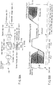
- FIG. 115 shows an example of a write-once type information storage medium to which the embodiment of the invention is applied.
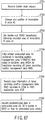
- FIG. 116 shows the steps of manufacturing the write-once type information storage medium shown in FIG. 115 .
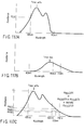
- FIGS. 117A to 117C show light absorbance characteristics of an organic dye material according to the invention.
- optical disk information storage medium
- the information specific to the information storage medium is used when there is a need for identifying individual optical disks (information storage media) by, for example, copy protection.
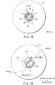
- information specific to such information storage media is engraved in advance at the inner periphery portion of the information storage medium as shown in FIG. 115 or FIG. 119 , as a bar-code shaped pattern called a burst cutting area (BCA) 2011 in the optical disk 2001.
- BCA burst cutting area
- a method for burning an aluminum (A1) reflection film with a laser light beam or the like is employed in the case where the BCA pattern 2012 is recorded in a reproduction-only or write-once type information storage medium.
- a recording film is phase-changed with a laser light beam, thereby fabricating a pattern.
- the embodiment uses a dye adjusted so as to have recording sensitivity at a wavelength of a laser light beam used as a laser light source of a current BCA recording apparatus.
- the dye is obtained by mixing an organic dye based recording material having absorption at a wavelength of 600 nm to 700 nm with an organic dye based recording material compatible with a wavelength of 405 nm.
- the information storage medium has a thickness of 1.2 mm at a diameter of 120 mm (by pasting two polycarbonate molded substrates of 0.6 mm), and is a write-once type information storage medium using an organic dye based recording material for a recording layer.
- an optical system which uses an objective lens whose numerical aperture (NA) is 0.65 at a wavelength of 405 nm.
- Track pitches among grooves in a data recording area are 400 nm (0.4 ⁇ m), and the burst cutting area BCA is 22. 2 mm to 23.1 mm in radius or 22.3 mm to 23.15 mm in radius.
- a BCA pattern 2012 is provided as a bar-code shaped pattern whose width (tangent direction) is some tens of ⁇ m and whose length (radial direction) is in order of some hundreds ⁇ m.
- the embodiment of the BCA pattern is not limited thereto.
- materials for the information storage medium include: polycarbonate for a molded substrate: nickel (Ni) for a stamper used for molding; an organic dye material including azo-based, diazo-based, cyanine-based, phthalocyanine-based, styryl-based, or a mixture thereof for a recording layer (organic dye film); sliver (Ag), aluminum (Al), gold (Au) or a metal component consisting primarily of these metals for a reflection film; and acryl-based or epoxy-based UV-curable resin for an adhesive. These materials are not limited to those according to the embodiment.
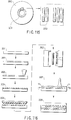
- a method for fabricating a write-once type information storage medium will be described here with reference to FIG. 116 .
- FIG. 116 a glass having the surface thereof polished and washed is used as a masterpiece (2021).
- a photo resist is coated on the surface of the masterpiece (2022), and information is recorded by exposing its surface with a laser light beam or the like (2023).
- the masterpiece is subjected to a plating process to thereby produce a stamper (whose material is generally nickel) (2025).
- a resin molded plate (whose material is generally polycarbonate) is produced by ejection molding (2026).
- an organic dye is coated by, for example, spin coating as a recording layer (2027).
- the reflection layer is pasted with another one molded substrate formed in advance, via an adhesive layer (2028).
- the bar-code shaped BCA pattern 2012 (refer to FIG. 115 ) specific to an information storage medium is recorded in the burst cutting area BCA of the pasted information storage medium, whereby a write-once type information storage medium (using the organic dye for the recording layer) can be obtained.
- a material having absorption at a wavelength of 600 nm to 700 nm is mixed with a dye material for a next-generation information storage medium compatible with a wavelength of 405 nm, so that BCA information can be recorded by a laser light source of the BCA recording apparatus using a laser light beam of 650 nm to 690 nm in currently widely used wavelength.
- Absorption characteristics of the organic dye is preferable as shown at the subsequent stage with reference to FIG. 117C .
- a BCA recording apparatus for a current standard DVD can be used as it is. In this case, in a production system in which a current standard DVD and next-generation standard DVD manufacturing lines are provided in parallel, there occurs an advantage that there is no need for newly introducing an expensive BCA recording apparatus having a short wavelength.
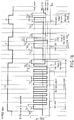
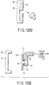
- FIGS. 120A to 120E and 121 illustrate the steps of manufacturing a transparent substrate in accordance with the injection molding method of the embodiment.
- a transparent resin pellet as a material for a transparent substrate is retained in a pellet storage section 35.
- pellets are melted and dissolved by being heated up to a predetermined temperature (the pellets are liquefied with fluidity).
- a gap section 34 is produced between a die 32 and a die 33, and a stamper 31 having a pre-pit in an emboss area or a pre-groove shape in a data area is mounted on the side of the die 33 in an ejection molding machine, as shown in FIG. 120A .
- the stamper 31 is fixed to a movable section 41.
- the die 33 can be reciprocally moved with a movement in a transverse direction (on the drawings) of the movable section 41 together with the pellet storage section 35.
- the die 32 is arranged at the side of a fixing section 40.
- a pellet 36 dissolved in the pellet storage section 35 is ejected at a predetermined pressure to the gap section 34 between the die 32 and the die 33 as shown in FIG. 120B , and the ejected pellet is cooled for a predetermined cooling time. Then, the cooled pallet is solidified as a transparent substrate 2-2 as shown in FIG. 120C .
- the die 33 in the movable section 41 is moved to the right side (in the figure), whereby the transparent substrate 2-2 is exposed.
- a center section of the transparent substrate 2-2 is cut, and a center hole 42 is formed at the center.
- the transparent substrate 2-2 is released from the fixing section 40 by a mold release member 50 of the transparent substrate.
- the mold release member 50 of the transparent substrate includes, for example, an arm 51, suction cups 52 to 55 (a total of four boards are provided although two boards 52 and 53 along the center axis are shown in the figure), an air guide 56, and a suction machine 57.
- the air guide 56 exists inside of the suction cup, and air is evacuated therefrom to suction the suction cup onto the transparent substrate 2-2.
- the suction cups 52 to 55 are brought into intimate contact with the transparent substrate 2-2.
- air 58 is evacuated by the suction machine 57 to establish the air guide 56 in the arm 51 in a vacuum state (or in a predetermined depressurized state), so that the suction cups 52 to 55 are brought into intimate contact with the transparent substrate 2-2.
- the arm 51 is retracted to a rear side (to a predetermined retracted position), so that the transparent substrate 2-2 is released from the fixing section 40.
- an organic dye that is a raw material for the recording layer 3-2 is coated in accordance with a spin coating method using a spinner, for example.
- FIG. 120E it is known that a suction force acting on the transparent substrate 2-2 from the suction cups 52 to 55 suctioned on the transparent substrate 2-2 is comparatively large, and traces (of the suction cups) remain as suction cup traces 61 to 64 as shown in FIG. 121 .
- the suction cup traces 61 to 64 remain even after the transparent substrate 2-2 has been washed.
- the recording layer (organic dye) 3-2 is fully coated on the recording surface (dye coated surface) of the transparent substrate 2-2 including the suction cup traces 61 to 64, coating non-uniformity may occur on the recording layer (organic dye) 3-2.
- a reflectance of the recording layer 3-2 obtained by coating and hardening an organic dye film changes due to an effect of the suction cup trace.
- a variation of the reflectance that affects a reproduction signal has been measured as a magnitude of the variation of the reflectance per one cycle of the disk.
- the magnitude of the variation is less than 10% (0.1, does not exceed 10%) at maximum in a disk having no suction cup trace.
- the embodiment is characterized in that the shape of a suction cup is optimized to reduce an outermost peripheral diameter value of a suction cup trace and that the recording layer 3-2 is formed outside of the outermost peripheral diameter value of the suction cup trace.
- the suction cups 52 to 55 shown in FIG. 120E are formed in a concentric shape relevant to suction cup traces 61 to 64 shown in FIG. 121 as seen in a planer direction. An outer diameter connecting them is significantly large as compared with a diameter of the center hole 42 of the transparent substrate 2-2, as indicated by a virtual line (circle) 66 (outermost peripheral diameter value ⁇ a in FIG. 121 .
- an outermost peripheral diameter value ⁇ b of a suction cup trace can be reduced to be smaller than the value of ⁇ a such that two adjacent suction cups are shaped to be integrated with each other, for example, two suction cups 71 and 72 formed in a banana shape (arc shape) are provided.
- a suction force relevant to the transparent substrate 2-2 is lowered by reducing the outermost peripheral diameter value ⁇ b of the suction cup trace. As shown in FIG. 118 , a suction area is broadened more than a circular suction cup (of a conventional type), thereby preventing the lowering of the suction force.
- FIG. 119 explains a range of forming the recording layer of the storage medium in the embodiment.
- An innermost peripheral diameter value ⁇ m of a recording layer forming area is greatly set with respect to the outermost peripheral diameter value ⁇ b connecting an outer diameter portion of the suction cup traces 71 and 72. As a result, coating non-uniformity of the recording layer is prevented from occurring due to the suction cup trace at the time of forming the recording layer.
- the innermost peripheral diameter value ⁇ b of the recording layer forming area is smaller than an innermost peripheral diameter ⁇ BCAin of the burst cutting area BCA ( ⁇ BCAin > ⁇ m).
- a width ⁇ of an area in which thickness variation of the recording layer (dye film) 3-2 occurs is 200 ⁇ m (0.2 mm)
- the value of ⁇ is 0.4 mm.
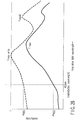
- FIG. 122 shows a relationship between a radial direction position of the write-once type information storage medium and a thickness distribution of the recording layer.
- an area in which thickness variation of the recording layer (dye film) 3-2 occurs is generated in the vicinity of the innermost peripheral diameter value ⁇ m of the recording layer forming area.
- a burst cutting signal in the burst cutting area BCA is produced by a recording processing relevant to the recording layer 3-2. Therefore, if thickness variation of the recording layer (dye film) 3-2 as shown in FIG. 122 occurs, the recording characteristics in the burst cutting area BCA change, and variation occurs with the reproduction signal therefrom.
- the burst cutting area is required to have a uniform thickness free of the thickness non-uniformity of the recording layer 3-2.
- a width of an area in which thickness variation shown in FIG. 122 occurs is ⁇
- a relationship of [ ⁇ /2 ⁇ ⁇ ] is requested as the value of ⁇ described above.
- a width of an area in which thickness variation occurs is generally equal to or smaller than 100 ⁇ m.
- FIG. (a) of 123 shows a relationship between the position of the burst cutting area that can be used for another embodiment and the innermost periphery of the recording layer forming area.
- FIG. (a) of 123 shows an example in which the innermost peripheral diameter value ⁇ m of the recording layer forming area is reduced by ⁇ to be smaller than the innermost peripheral diameter ⁇ BCAin of the burst cutting area BCA.
- the recording layer 3-2 may exist by a width of ⁇ /2 in the burst cutting area BCA.
- the innermost peripheral diameter value of the burst cutting area BCA is ⁇ 44.6+ 0.0 -0.8 mm, whereas the outermost peripheral diameter value of the burst cutting area BCA is ⁇ 46.3 ⁇ 0.1. Consequently, a differential value between these values is obtained as 1.7 mm, and the width of the burst cutting area is obtained as 0.85 mm (that is 1/2 of the differential value).
- the innermost peripheral diameter of the system lead-in area is 46.6 mm, and ⁇ is 100 ⁇ m or larger, desirably 200 ⁇ m or greater.
- a BCA area formed of an organic dye and an optical disk i.e., an information storage medium, having such a BCA area
- the data area and data structure as well as recording characteristics strongly depend on a recording/reproducing apparatus for recording information in the information storage medium or reproducing information that has already been recorded, or alternatively, for eliminating information and a standard (specification) applied to the recording/reproducing apparatus or an arbitrary combination thereof. From the background, a detailed description will be additionally given below with respect to a data area and a data structure as well as recording characteristics of an optical disk (information storage medium), and a recording/reproducing apparatus.
- a write-once type optical disk obtained by using an organic dye material for a recording medium there has been commercially available a CD-R disk using a recording/reproducing laser light source wavelength of 780 nm and a DVD-R disk using a recording/reproducing laser light beam wavelength of 650 nm. Further, in a next-generation write-once type information storage medium having achieved high density, it is proposed that a laser light source wavelength for recording or reproducing, which is close to 405 nm (namely, in the range of 355 nm to 455 nm), is used in either of H format (D1) and B format (D2) of FIG. 1 described later. In a write-once type information storage medium using an organic dye material, recording/reproducing characteristics sensitively changes due to a slight change of a light source wavelength.
- density is increased in inverse proportion to a square of a laser light source wavelength for recording/reproducing, and thus, it is desirable that a shorter laser light source wavelength be used for recording/reproducing.
- an organic dye material utilized for a CD-R disk or a DVD-R disk cannot be used as a write-once type information storage medium for 405 nm.
- 405 nm is close to an ultraviolet ray wavelength, there can easily occur a disadvantage that a recording material "which can be easily recorded with a light beam of 405 nm", is easily changed in characteristics due to ultraviolet ray irradiation, lacking a long period stability.
- Characteristics are significantly different from each other depending on organic dye materials to be used, and thus, it is difficult to determine the characteristics of these dye materials in general. As an example, the foregoing characteristics will be described by way of a specific wavelength. With respect to an organic dye recording material optimized with a light beam of 650 nm in wavelength, the light to be used becomes shorter than 620 nm, recording/reproducing characteristics significantly change. Therefore, in the case where a recording/reproducing operation is carried out with a light beam which is shorter than 620 nm in wavelength, there is a need for new development of an organic dye material which is optimal to a light source wavelength of recording light or reproducing light.
- a description will be given with respect to an embodiment relevant to an organic recording material suitable to use in close to 405 nm.
- the scope of the embodiment corresponds to a light beam which is adapted to a light source of 620 nm in wavelength, and desirably, which is shorter than 530 nm in wavelength (ranging from 355 nm to 455 nm in a definition in the narrowest range).
- the optical recording sensitivity due to light absorption spectra of an organic dye material is also influenced by a recording wavelength.
- An organic dye material suitable for long period stability is easily reduced in light absorbance relevant to a light beam which is shorter than 620 nm in wavelength.
- the light absorbance is significantly lowered with respect to a light beam which is shorter than 620 nm in wavelength, and in particular, is drastically reduced with respect to a light beam which is shorter than 530 nm in wavelength.
- the size of a focusing spot used for recording or reproducing application is reduced in proportion to a wavelength of a light beam to be used. Therefore, from only a standpoint of the focusing spot size, in the case where a wavelength is reduced to the above described value, an attempt is made to reduce a track pitch or channel bit length by a wavelength component with respect to a current DVD-R disk (use wavelength: 650 nm) which is a conventional technique.
- a track pitch or a channel bit length can be reduced in proportion to the above described wavelength by utilizing a technique devised in the embodiment described below.
- an organic recording medium material (organic dye material) adapted to a light source of 620 nm or less in wavelength
- organic recording medium organic dye material
- Such an organic recording medium has a unique characteristic (Low to High characteristic) that a light reflection factor increases in a recording mark, which does not exist in a conventional CD-R disk or a DVD-R disk. Therefore, a technical feature of the embodiment and a novel effect attained thereby occurs in a structure, dimensions, or format (information recording format) combination of the information storage medium which produces more effectively the characteristics of the organic recording material (organic dye materials) shown in the embodiment.
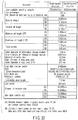
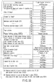
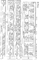
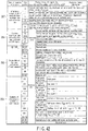
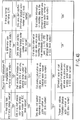
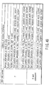
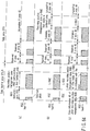
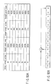
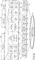
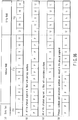
- FIG. 1 shows a combination, which produces a new technical feature and advantageous effect in the embodiment. That is the information storage medium in the embodiment has the following constituent elements:
- constituent elements correspond to the contents described in each column of FIG. 1 .
- a technical feature and a unique advantageous effect of the embodiment occur in combination of the specific embodiments of the constituent elements shown in FIG. 1 .
- a description will be given with respect to a combination state of individual embodiments at a stage of explaining the embodiments.
- constituent elements which do not specify a combination, it denotes that the following characteristics are employed:
- FIG. 2A shows a standard phase change recording film structure (mainly used for a rewritable-type information storage medium), and FIG. 2B shows a standard organic dye recording film structure (mainly used for a write-once type information storage medium).
- a whole recording film structure excluding transparent substrates 2-1 and 2-2 shown in FIGS. 2A and 2B is defined as a "recording film", and is discriminated from recording layers 3-1 and 3-2 in which a recording material is disposed.
- a recording material using a phase change in general, an optical characteristic change amount in a recorded area (in a recording mark) and an unrecorded area (out of a recording mark) is small, and thus, there is employed an enhancement structure for enhancing a relative change rate of a reproduction signal.
- an undercoat intermediate layer 5 is disposed between the transparent substrate 2-1 and a phase change type recording layer 3-1, and an upper intermediate layer 6 is disposed between the light reflection layer 4-2 and the phase change type recording layer 3-1.
- a material for the transparent substrates 2-1 and 2-2 there is employed a polycarbonate PC or an acrylic PMMA (poly methyl methacrylate) which is a transparent plastic material.
- a center wavelength of a laser light beam 7 used in the embodiment is 405 nm, and refractive index n 21 , n 22 of the polycarbonate PC at this wavelength is close to 1.62.
- Standard refractive index n 31 and absorption coefficient k 31 in 405 nm at GeSbTe (germanium antimony tellurium) which is most generally used as a phase change type recording material are n 31 ⁇ 1.5 and k 31 ⁇ 2.5 in a crystalline area, whereas they are n 31 ⁇ 2.5 and k 31 ⁇ 1.8 in ⁇ an amorphous area.
- a refractive index (in the amorphous area) of a phase change type recording medium is different from a refractive index of the transparent substrate 2-1, and reflection of a laser light beam 7 on an interface between the layers is easily occurred in a phase change recording film structure.
- a phase change recording film structure takes an enhancement structure; and (2) a refractive index difference between the layers is great or the like, a light reflection amount change at the time of reproduction from a recording mark recorded in a phase change recording film (a differential value of a light reflection amount from a recording mark and a light reflection amount from an unrecorded area) can be obtained as an interference result of multiple reflection light beams generated on an interface between the undercoat intermediate layer 5, the recording layer 3-1, the upper intermediate layer 6, and the light reflection layer 4-2.
- FIG. 2A although the laser light beam 7 is apparently reflected on an interface between the undercoat intermediate layer 5 and the recording layer 3-1, an interface between the recording layer 3-1 and the upper intermediate layer 6, and an interface between the upper intermediate layer 6 and the light reflection layer 4-2, in actuality, a reflection light amount change is obtained as an interference result between a plurality of multiple reflection light beams.
- an organic dye recording film structure takes a very simple laminate structure made of an organic dye recording layer 3-2 and a light reflection layer 4-2.
- An information storage medium (optical disk) using this organic dye recording film is called a write-once type information storage medium, which enables only one time of recording.
- an optical reproduction principle of an organic color recording film (reason why a reflection light amount change occurs) is not “multiple interference” in a phase change recording film, and a main factor is a "light amount loss (including interference) midway of an optical path with respect to the laser light beam 7 which comes back after being reflected in the light reflection layer 4-2".
- the light reflection factor of the organic dye recording film in an unrecorded area on a mirror surface on which a pre-groove or a pre-pit does not exist is featured to be simply obtained by a value obtained by subtracting an optical absorption amount when the recording layer 3-2 is passed from the light reflection factor of the laser light beam 7 in the light reflection layer 4-2.
- this film is different from a phase change recording film whose light reflection factor is obtained by calculation of "multiple interference".
- the transparent substrate 2-2 is locally plastically deformed, there changes an optical distance of the laser light beam 7 reflected in the light reflection layer 4-2 through the transparent substrate 2-2, the laser light beam 7 coming back through the transparent substrate 2-2 again.
- a phase difference occurs between the laser light beam 7 from a recording mark, the laser light beam coming back through a portion of the locally plastically deformed transparent substrate 2-2, and a laser light beam 7 from the periphery of the recording mark, the laser light beam coming back through a portion of a transparent substrate 2-2 which is not deformed, and thus, a light amount change of reflection light beam occurs due to interference between these light beams.
- a change of a substantial refractive index n 32 produced by cavitation of the inside of the recording mark in the recording layer 3-2 due to gasification (evaporation), or alternatively, a change of a refractive index n 32 produced due to thermal decomposition of an organic dye recording material in the recording mark also contributes to the above described occurrence of a phase difference.
- the recording layer 3-2 can absorb energy of the laser light beam 7 at a first stage.
- the light absorption spectra in the recording layer 3-2 influence the recording sensitivity of an organic dye recording film.
- a principle of light absorption in an organic dye recording material which forms the recording layer 3-2 will be described with reference to (A3) of the embodiment.
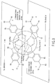
- FIG. 3 shows a specific structural formula of the specific contents "(A3) azo metal complex + Cu" of the constituent elements of the information storage medium shown in FIG. 1 .
- a circular periphery area around a center metal M of the azo metal complex shown in FIG. 3 is obtained as a light emitting area 8.
- the localization range of local electrons around the center metal M (how large the center metal M can attract the local electrons to the vicinity of the center) is changed by changing atoms of the center metal M, and the value of the maximum absorption wavelength ⁇ max changes.
- the light absorption spectra of the organic dye recording material in the case where there exists only one light emitting area 8 which is absolute 0 degree at a temperature and high in purity draws narrow linear spectra in close to a maximum absorption wavelength ⁇ max
- the light absorption spectra of a general organic recording material including impurities at a normal temperature, and further, including a plurality of light absorption areas exhibit a wide light absorption characteristic with respect to a wavelength of a light beam around the maximum absorption wavelength ⁇ max .
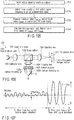
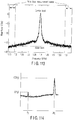
- FIG. 4 shows an example of light absorption spectra of an organic dye recording material used for a current DVD-R disk.
- a wavelength of a light beam to be irradiated with respect to an organic dye recording film formed by coating an organic dye recording material is taken on a horizontal axis, and absorbance obtained when an organic dye recording film is irradiated with a light beam having a respective wavelength is taken on a vertical axis.
- the absorbance used here is a value obtained by entering a laser light beam having incident intensity Io from the side of the transparent substrate 2-2 with respect to a state in which a write-once type information storage medium has been completed (or alternatively, a state in which the recording layer 3-2 has been merely formed on the transparent substrate 2-2 (a state that precedes forming of the optical reflection layer 4-2 with respect to a structure of FIG. 2B )), and then, measuring reflected laser light intensity Ir (light intensity It of the laser light beam transmitted from the side of the recording layer 3-2).
- the absorbance Ar (At) is represented by: Ar ⁇ - log 10 Ir / Io and Ar ⁇ - log 10 It / Io
- absorbance Ar of a reflection shape expressed by formula (A-1) it is possible to define absorbance At of a transmission shape expressed by formula (A-2) without being limited thereto in the embodiment.
- absorbance At of a transmission shape expressed by formula (A-2) there exist a plurality of light absorption areas, each of which includes the light emitting area 8, and thus, there exist a plurality of positions at which the absorbance becomes maximal.
- a wavelength of the recording laser light in the current DVD-R disk is set to 650 nm.
- a value of the maximum absorption wavelength ⁇ max which is the closest to the wavelength of the recording laser light beam becomes important. Therefore, only in the description of the embodiment, the value of the maximum absorption wavelength ⁇ max set at a position which is the closest to the wavelength of the recording laser light beam is defined as ⁇ max write"; and is discriminated from another ⁇ max ( ⁇ max 0) .
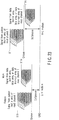
- FIGS. 5A and 5B each show a comparison in shape when a recording film is formed in a pre-pit area or a pre-groove area 10.
- FIG. 5A shows a shape relevant to a phase change recording film.
- any of methods of sputtering vapor deposition, vacuum vapor deposition, or ion plating is used in vacuum.
- FIG. 5B shows a general recording film sectional shape of a current DVD-R disk which is a conventional technique as a recording film in the case where an organic dye recording film has been used.
- a method for forming the recording film 3-2 there is used a method called spin coating (or spinner coating) which is completely different from that shown in FIG. 5A .
- the spin coating used here denotes a method for dissolving in an organic solvent an organic dye recording material which forms the recording layer 3-2; applying a coating onto the transparent substrate 2-2; followed by rotating the transparent substrate 2-2 at a high speed to spread a coating agent to the outer periphery side of the transparent substrate 2-2 by a centrifugal force; and gasifying the organic solvent, thereby forming the recording layer 3-2.
- a process for coating the organic solvent is used, and thus, a surface of the recording layer 3-2 (an interface with the light reflection layer 2-2) is easily flattened.
- the sectional shape on the interface between the light reflection layer 2-2 and the recording layer 3-2 is obtained as a shape which is different from the shape of the surface of the transparent substrate 2-2 (an interface between the transparent substrate 2-2 and the recording layer 3-2).
- the sectional shape on the interface between the light reflection layer 2-2 and the recording layer 3-2 is formed in a substantially V-shaped groove shape.
- the above sectional shape is formed in a substantially conical side surface shape. Further, at the time of spin coating, an organic solvent is easily collected at a recessed portion, and thus, the thickness Dg of the recording layer 3-2 in the pre-pit area or pre-groove area 10 (i.e., a distance from a bottom surface of the pre-pit area or pre-groove area to a position at which an interface relevant to the light reflection layer 2-2 becomes the lowest) is larger than the thickness D1 in a land area 12 (Dg > D1).
- an amount of irregularities on an interface between the transparent substrate 2-2 and the recording area 3-2 in the pre-pit area or pre-groove area 10 becomes substantially smaller than an amount of irregularities on the transparent substrate 2-2 and the recording layer 3-2.
- the shape of irregularities on the interface between the light reflection layer 2-2 and the recording layer 3-2 becomes blunt and an amount of irregularities becomes significantly small.
- the shape and dimensions of irregularities on a surface of the transparent substrate 2 pre-pit area or pre-groove area 10 are equal to each other depending on a difference in method for forming a recording film, the diffraction intensity of the reflection light beam from the organic dye recording film at the time of laser light irradiation is degraded more significantly than the diffraction intensity of the reflection light beam from the phase change recording film.
- a width W1 of the land area 12 is larger than a width Wg of the pre-pit area or pre-groove area 10 (Wg > W1).
- a general principle of recording of a current DVD-R and CD-R which is a write-once type information storage medium using a conventional organic dye material includes "local plastic deformation of transparent substrate 2-2" or “local thermal decomposition or "gasification” in recording layer 3-2".
- FIGS. 6A and 6B each show a plastic deformation state of a specific transparent substrate 2-2 at a position of a recording mark 9 in a write-once type information storage medium using a conventional organic dye material.
- FIG. 6B a bottom surface 14 in a pre-groove area at the position of the recording mark 9 is distorted and is slightly curved (the flatness of the bottom surface 14 is distorted: In the example shown in FIG. 6B , the bottom surface 14 in the pre-groove area at the position of the recording mark 9 is slightly curved toward the lower side).
- the plastic deformation range of the transparent substrate 2-2 at the position of the recording mark 9 covers a wide range, and thus, the adjacent tracks are adversely affected, and the recording mark 9 of the existing adjacent track is substantially erased (cannot be reproduced) due to a "cross-write" or overwrite in which the recording mark 9 widens to the adjacent tracks.
- the channel bit length is narrower than 0.133 ⁇ m, there occurs a problem that inter-code interference appears; an error rate at the time of reproduction significantly increases; and the reliability of reproduction is lowered.
- a difference in its optical difference is mainly caused by "a change of the thickness Dg of a physical recording layer 3-2 due to plastic deformation of the transparent substrate 2-2 (a physical distance from an interface between the transparent substrate 2-2 and the recording layer 3-2 to an interface between the recording layer 3-2 and a light reflection layer 4-2) and "a change of refractive index n 32 of the recording layer 3-2 in the recording mark 9".
- condition for formula (3) becomes a condition, which should be met, in the embodiment in which plastic deformation of the transparent substrate 2-2 does not occur.
- the range of the thickness Dg can be specified.
- a step amount between a pre-pit area and a land area is ⁇ /(8n 21 ) when the largest track shift detection signal is obtained by using a push-pull technique.
- an organic dye recording film shown in FIG. 5B as described previously, the shape on an interface between the recording layer 3-2 and the light reflection layer 4-2 becomes blunt, and a step amount becomes small.
- the refractive index at 405 nm in the case where polycarbonate has been used as a material for the transparent substrate 2-2 is n 22 ⁇ 1.62, and thus, it is necessary to increase a step amount between the pre-pit area and the land area more significantly than 31 nm.
- condition for formula (4) is also a condition, which should be met in the embodiment in which plastic deformation of the transparent substrate 2-2 does not occur.
- k 32 0.1 to 0.2 has been assumed as a value of an absorption coefficient of the organic dye recording film 3-2 at 405 nm.
- the channel bit length is slightly lower than 105 nm, it is considered that a lengthwise change in a direction along a track in an area which reaches the thermal deformation temperature at the side of the transparent substrate 2-2 occurs according to the slight change of recording power, and a sufficient window margin cannot be obtained.
- the NA value is any one of 0.60, 0.65, and 0.85.
- a thermal spreading range is wide (a gradient of a temperature distribution at the side of the transparent substrate 2-2 which comes into contact with the recording layer 3-2) is comparatively gentle).
- the temperature distribution at the side of the transparent substrate 2-2 which comes into contact with the recording layer 3-2 is discussed, and thus, an effect of the thickness Dg of the recording layer 3-2 does not appear.
- a glass transition temperature 150°C of a polycarbonate resin has been presumed as an arrival temperature at the time of substrate deformation in the above discussion, a temperature difference between 150°C and 220°C is small, and, when the transparent substrate 2-2 reaches 150°C, the inside of the recording layer 3-2 exceeds 220°C.
- a temperature at which a structural change of the organic dye recording material occurs in the recording layer 3-2 and a value of a refractive index n 32 or an absorption coefficient k 32 starts its change is much lower than an arrival temperature for the transparent substrate 2-2 to start thermal deformation. Therefore, the value of the refractive index n 32 or absorption coefficient k 32 changes in a comparatively wide range in the recording layer 3-2 at the periphery of a recording mark 9, which is thermal deformed at the side of the transparent substrate 2-2, and this change seems to cause "cross-write” or "cross-erase” for the adjacent tracks.
- the embodiment is primarily featured in "inventive organic dye material” in which "a local optical characteristic change in the recording layer 3-2, which occurs at a comparatively low temperature, is a principle of recording” and “setting environment (recording film structure or shape) in which the above principle of recording easily occurs without causing a substrate deformation and gasification (evaporation) in the recording layer 3-2.
- Specific characteristics of the embodiment can be listed below.
- the light emitting area 8 is partially destroyed or the size of the light emitting area 8 changes, whereby a substantial light absorption sectional area changes. In this manner, an amplitude (absorbance) at a position of ⁇ max write changes in the recording mark 9 while a profile (characteristics) of light absorption spectra ( FIG. 4 ) itself is maintained.
- the exposure amount (recording power) at the time of recording is reduced to prevent the deformation temperature from being exceeded on the surface of the transparent substrate 2-2 or the gasification (evaporation) temperature from being exceeded in the recording layer 3-2.
- the contents will be described later in detail in the section "3-3) Recording characteristics common to organic dye recording layer in the embodiment".
- PRML Partial Response Maximum Likelihood
- a passage speed (line speed) of a focusing spot of light passing through the recording layer 3-2 is set to 6.61 m/s
- the line speed in the B format is set in the range of 5.0 m/s to 10.2 m/s.
- the line speed at the time of reproduction in the embodiment is equal to or greater than 5 m/s.
- a start position of a data lead-in area DTLDI in the H format is 47.6 mm in diameter.
- user data is recorded in location equal to or greater than 45 mm in diameter.
- Video image information such as TV program is provided as one of the methods utilizing a write-once type information storing medium according to the embodiment. For example, when a user presses "pause (temporary stop) button" at the reproduction of the user's recorded video image, a reproduction focusing spot stays on a track of its paused position. When the spot stops on the track of the paused position, the user can start reproduction at the paused position immediately after a "reproduction start button" has been pressed.
- a "pause (temporary stop) button” in the case where a customer visits the user's home immediately after the user has gone to toilet, there is a case in which the pause button is left to have been pressed for one hour while the user meets the customer.
- the write-once type information storage medium makes 35.4 ⁇ 60 ⁇ 60 ⁇ 130,000 rotations for one hour, and the focusing spot traces on the same track during this period (130,000 repetitive playbacks). If the recording layer 3-2 is degraded due to repetitive playback and video image information cannot be reproduced after this period, the user coming back one hour later cannot see any portion of video image, and thus, gets angry, and in the worst case, there is a danger that the problem may be taken to court.
- the write-once type information storage medium according to the embodiment desirably makes 1,000,000 repetitive playbacks, no problem occurs with use by the general user, and it is considered sufficient to set to about 1,000,000 times the upper limit value of the repetitive playback count as long as the recording layer 3-2 is not degraded.
- recording power is defined in a range set in formulas (8) to (13).
- a semiconductor laser beam is featured in that continuous light irradiation is not stable in a value equal to or smaller than 1/80 of the maximum use power. Because the power, which is 1/80 of the maximum use power, is in location in which light irradiation is just started (mode initiation is started), mode hopping is likely to occur. Therefore, at this light irradiation power, the light reflected in the light reflection layer 4-2 of the information storage medium comes back to a semiconductor laser light source, there occurs a "return light noise" featured in that the light emission amount always changes.
- the values of the reproduction power is set below around the value which is 1/80 of the value described at the right side of formula (12) or formula (13): Optical reproduction power > 0.19 ⁇ 0.65 / NA 2 ⁇ V / 6.6 Optical reproduction power > 0.19 ⁇ 0.65 / NA 2 ⁇ V / 6.6 1.2
- the value of the optimal reproduction power is restricted by a dynamic range of a power monitoring optical detector.
- a recording/reproducing optical head incorporates an optical detector which monitors a light emission amount of a semiconductor laser light source.
- this optical detector detects a light emission amount and applies a feedback to an amount of a current to be supplied to the semiconductor laser light source at the time of light irradiation.
- a commercially available, inexpensive optical detector is often molded with a resin (an optical detecting unit is surrounded).
- 530 nm or less (in particular, 455 nm or less) is used as a light source wavelength in the embodiment.
- a resin with which the optical detecting unit is molded mainly, epoxy resin
- a mold resin degradation is likely to occur because the storage medium has a pre-groove area 11 as shown in FIGS. 8A, 8B and 8C .
- a focus blurring detection system of an optical head in order to remove adverse effect due to the diffraction light from this pre-groove area 11, there is most often employed a "knife-edge technique" of allocating an optical detector at an image forming position relevant to the information storage medium (image forming magnification M is in order of 3 times to 10 times).
- a temperature difference ⁇ T write ranges from 65°C to 135°C. Pulse light emissions occur at the time of recording, and continuous light emissions occur at the time of reproduction. At the time of reproduction, the temperature rises in the recording layer 3-2 and a temperature difference ⁇ T read occurs.
- an image forming magnification of a detecting system in the optical head is M
- the optical density of the detected light focused on the optical detector is obtained as 1/M 2 of the optical density of convergence light irradiated on the recording layer 3-2, and thus, a temperature rise amount on the optical detector at the time of reproduction is obtained as ⁇ T read /M 2 which is a rough estimate.
- an upper limit value of optical density which can be irradiated on the optical detector, is converted by the temperature rise amount, it is considered that the upper limit value is in order of ⁇ T read /M 2 ⁇ 1°C.
- the image foaming magnification of the detecting system in the optical head M is in order of 3 times to 10 times in general, if the magnification M 2 ⁇ 10 is tentatively estimated, it is necessary to set reproduction power so as to obtain: ⁇ T read / ⁇ T write ⁇ 20
- optimal reproduction power is assigned as follows: Optical reproduction power ⁇ 3 ⁇ 0.65 / NA 2 ⁇ V / 6.6 Optimal reproduction power ⁇ 3 ⁇ 0.65 / NA 2 ⁇ V / 6.6 1 / 2 Optimal reproduction power ⁇ 2 ⁇ 0.65 / NA 2 ⁇ V / 6.6 Optimal reproduction power ⁇ 2 ⁇ 0.65 / NA 2 ⁇ V / 6.6 1 / 2 Optimal reproduction power ⁇ 1.5 ⁇ 0.65 / NA 2 ⁇ V / 6.6 Optimal reproduction power ⁇ 1.5 ⁇ 0.65 / NA 2 ⁇ V / 6.6 1 / 2
- Optimal reproduction power ⁇ 3 mW Optimal reproduction power ⁇ 2 mW
- Optimal reproduction power ⁇ 1.5 mW Optimal reproduction power
- the optical detector is fixed as compared with the fact the information storage medium rotates and relatively moves, and thus, in consideration of this fact, it is necessary to further set the optimal reproduction power to be in order of 1/3 or less of the value obtained in the above formula.
- a value of the reproduction power is set to 0.4 mW.
- the embodiment is featured in that a technical contrivance is carried out in recording film structure or shape such as:
- FIGS. 7A, 7B and 7C the open (blank) arrow indicates an optical path of an irradiation laser light beam 7, and the arrow of the dashed line indicates a thermal flow.
- a recording film structure shown in FIG. 7A indicates an environment in which an optical characteristic change inside of a recording layer 3-2 corresponding to the embodiment is most likely to occur. That is, in FIG. 7A , the recording layer 3-2 consisting of an organic dye recording material has uniform thickness anywhere in the range shown in formula (3) or formula (4) (where the thickness is sufficiently large), and receives irradiation of the laser light beam 7 in a direction vertical to the recording layer 3-2. As described in detail in "6-1) light reflection layer (material and thickness)", a silver alloy is used as a material for a light reflection layer 4-2 in the embodiment.
- a material including a metal with high light reflection factor in general, has high thermal conductivity and heat radiation characteristics without being limited to the silver alloy. Therefore, although a temperature of the recording layer 3-2 is risen by absorbing the energy of the irradiated laser light beam 7, a heat is radiated toward the light reflection layer 4-2 having heat radiation characteristics.
- a recording film shown in FIG. 7A is formed anywhere in a uniform shape, a comparatively uniform temperature rise occurs inside of the recording layer 3-2, and a temperature difference at points ⁇ , ⁇ , and ⁇ at the center part is comparatively small. Therefore, when the recording mark 9 is formed, when a critical temperature at which an optical characteristic change at the points ⁇ and ⁇ occurs is exceeded, a gasification (evaporation) temperature is not exceeded at the point ⁇ of the center part; and a surface of a transparent substrate (not shown) which exists at a position which is the closest to the point ⁇ of the center part does not exceed a thermal deformation temperature.
- a step is provided partly of the recording film 3-2.
- the radiation of the laser light beam 7 is subjected in a direction oblique to a direction in which the recording layer 3-2 is arrayed, and thus, an irradiation amount of the laser light beam 7 per a unit area is relatively lowered as compared with the point ⁇ of the center part.
- a temperature rise amount in the recording layer 3-2 at the points ⁇ and ⁇ is lowered.
- thermal radiation toward the light reflection layer 4-2 occurs, and thus, the arrival temperature at the points ⁇ and ⁇ is sufficiently lowered as compared with the point ⁇ of the center part. Therefore, a heat flows from the point ⁇ to the point ⁇ and a heat flows from the point ⁇ to the point ⁇ , and thus, a temperature difference at the points ⁇ and ⁇ relevant to the point ⁇ of the center part becomes very small.
- a temperature difference at the point ⁇ of the center part relevant to the points ⁇ and ⁇ is very large.
- a gasification (evaporation) temperature is exceeded at the point ⁇ of the center part or the surface of a transparent substrate (not shown) in the vicinity of the point ⁇ of the center part hardly exceeds a thermal deformation temperature.
- the thickness Dg of the recording layer 3-2 is sufficiently large, thus making it possible to achieve heat accumulation and to achieve a high temperature.
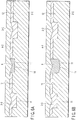
- FIGS. 8A, 8B and 8C Based on the contents described above, referring to FIGS. 8A, 8B and 8C , a description will be given with respect to: the contents of a technical contrivance in the embodiment relating to the pre-groove shape/dimensions for providing "setting of environment (structure or shape of a recording film)" in which a principle of recording according to the embodiment is likely to occur; and the contents of a technical contrivance in the embodiment relating to a thickness distribution of the recording layer.
- FIG. 8A shows a recording film structure in a conventional write-once type information storage medium such as CD-R or DVD-R; and FIGS. 8B and 8C each show a recording film structure in the embodiment.
- a recording mark 9 is formed in a pre-groove area 11.
- FIG. 8A there have been many cases in which a pre-groove area 11 is formed in a "V-groove" shape in a conventional write-once type information storage medium such as CD-R or DVD-R.
- a conventional write-once type information storage medium such as CD-R or DVD-R.
- FIG. 7B the energy absorption efficiency of the laser light beam 7 is low, and the temperature distribution non-uniformity in the recording layer 3-2 becomes very large.
- the embodiment is featured in that, in order to make close to an ideal state of FIG. 7A , a planar shape orthogonal to a traveling direction of the incident laser light beam 7 is provided in the pre-groove area 11 at the side of at least the "transparent substrate 2-2". As described with reference to FIG. 7A , it is desirable that this planar area be as wide as possible. Therefore, the embodiment is secondarily featured in that the planar area is provided in the pre-groove area 11 and the width Wg of the pre-groove area 11 is wider than the width Wl of a land area (Wg > W1).
- the width Wg of the pre-groove area and the width W1 of the land area are defined as their respective widths at a position at which there crosses a plane having an intermediate height between a height at a planar position of the pre-groove area and a height at a position at which the land area becomes the highest and an oblique surface in the pre-groove.
- a pre-pit (land pre-pit: not shown) is formed in the land area 12, and a format for recording address information or the like in advance is realized here.
- a wobble signal has been recorded in the pre-groove area 11 by means of frequency modulation.
- slot gaps are not constant, and phase adjustment at the time of wobble signal detection (PLL: synchronization of PLL (Phase Lock Loop)) has been comparatively difficult.
- PLL Phase Lock Loop
- a wall face of the pre-groove area 11 is concentrated (made close to the V-groove) in the vicinity of a center at which the intensity of a reproducing focusing spot is the highest and a wobble amplitude amount is increased, whereby the wobble signal detection precision has been guaranteed.
- the embodiment is featured in that the width Wg of the pre-groove area described above is widened and the H format utilizing PSK (Phase Shift Keying) in which slot gaps at wobble detection is always fixedly maintained or the B format utilizing FSK (Frequency Shift Keying) or STW (Saw Tooth Wobble) are combined, whereby stable recording characteristics are guaranteed (suitable to high speed recording or layering) at low recording power and stable wobble signal detection characteristics are guaranteed.
- PSK Phase Shift Keying
- FSK Frequency Shift Keying
- STW Scw Tooth Wobble
- the thickness in a portion at which the recording layer 3-2 in the land area 12 is the thickest is defined as recording layer thickness D1 in the land area 12; and a portion at which the recording layer 3-2 in the pre-groove area 11 is the thickest is defined as recording layer thickness Dg in the pre-groove area.
- the recording layer thickness D1 in the land area is relatively increased, whereby a local optical characteristic change in the recording layer is stably likely to occur at the time of recording.
- the embodiment is featured by recording power control, as described in item [ ⁇ ].
- the formation of the recording mark 9 due to a local optical characteristic change in the recording layer 3-2 occurs at a temperature, which is much lower than a plastic deformation temperature of the conventional transparent substrate 2-2, at a thermal decomposition temperature in the recording layer 3-2, or a gasification (evaporation) temperature.
- an upper limit value of recording power is restricted so as not ensure that the transparent substrate 2-2 locally exceeds a plastic deformation temperature at the time of recording or a thermal decomposition temperature or a gasification (evaporation) temperature is locally exceeded in the recording layer 3-2.
- NA numerical aperture
- a temperature of the transparent substrate 2-2 at a position in the vicinity of the recording layer 3-2 reaches a plastic deformation temperature (glass transition temperature) at 20 mW; 15 mW or less is desirable in consideration of a margin such as surface pre-warping or recording power change of an information storage medium.
- the "recording power" described above denotes a sum of exposure amount irradiated to the recording layer 3-2.
- the optical energy density at a center part of a focusing spot and at a portion at which the optical intensity density is the highest is obtained as parameters targeted for discussion in the embodiment.
- the focusing spot size is inversely proportional to the NA value, and thus, the optical energy density at the center part of the focusing spot increases in proportion to a square of the NA value. Therefore, the current value can be converted to a value of optimal recording power in the B format described later or another format (another NA value) shown in FIG. 1 (D3) by using a relational formula below.
- optimal recording power changes depending on a line speed V in phase change type recording material.
- optimal recording power changes in proportion to a 1/2 square of a line speed V in phase change type recording material, and changes in proportion to a line speed V in organic dye recording material. Therefore, a conversion formula of optimal recording power considering a line speed V, obtained by extending formula (5), is obtained as follows:
- a condition for formula (8) or formula (9) is obtained as a mandatory condition; a target condition for formula (10) or formula (11) is obtained; and a condition for formula (12) or formula (13) is obtained as a desirable condition.
- a recording film having characteristics that a light reflection amount in a recording mark 9 is lower than that in an unrecorded area is referred to as an "H-L” recording film.
- a recording film in which the above light reflection amount is high is referred to as an "L-H” recording film.
- the embodiment is featured in that:
- a wavelength of ⁇ max write is shorter than a use wavelength utilized for recording/reproduction (in the vicinity of 405 nm).
- a change of absorbance is small between an unrecorded portion and a recorded portion.
- a design of the recording film 3-2 is made so that a wavelength of ⁇ max write arrives at the outside ranging from 355 nm to 455 nm, i.e., arrives at the shorter wavelength side than 355 nm.
- the light reflection factor of the light reflection layer 4-2 is defined as 100% for the sake of simplification.
- a reproduction circuit is used in common to a case of using a read-only type information storage medium (HD DVD-ROM disk) in the case of a one-sided single layer film.
- an optical reflection factor is defined as 45% to 85% in accordance with a light reflection factor of the reflection only information storage medium (HD DVD-ROM disk) of a one-sided single layer film. Therefore, it is necessary to set the light reflection factor at an unrecorded position to 40% or more.
- the light reflection factor can be set to 40% or more.
- an organic dye recording material which meets formula (14) in an unrecorded location, is selected.
- the formula (14) assumes that, in FIG. 9 , the light reflection factor is obtained as 0% when the light reflection layer 4-2 is reflected over the recording layer 3-2 with a light beam having a wavelength of ⁇ max write . However, in reality, at this time, the light reflection factor is not obtained as 0%, and has a certain degree of light reflection factor. Thus, strictly, there is a need for correction relevant to formula (14).
- a light absorption spectrum profile is changed.
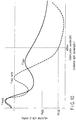
- the light absorption spectrum profile in a recording mark in the embodiment is indicated by the solid line shown in FIG. 10 , and the light absorption spectrum profile in an unrecorded location is superimposed by the dashed line, thereby making it possible to compare these profiles with each other.
- the light absorption spectrum profile in the recording mark changes comparatively broadly, and there is a possibility that a molecular structure change in molecules occurs and partial precipitation (coal tar) of carbon atoms occurs.
- the one of the embodiment is featured in that a value of a wavelength ⁇ 1 max at which the absorbance in the recording mark becomes maximal is made closer to a reproduction wavelength of 405 nm than a value of a wavelength ⁇ max write at an unrecorded position, thereby generating a reproduction signal in the "H-L" recording film.
- the absorbance at the wavelength ⁇ 1 max at which the absorbance is the highest becomes smaller than "1"
- a value of the absorbance Al 405 at a reproduction wavelength of 405 nm becomes greater than a value of Ah 405 .
- a total light reflection factor in a recording mark is lowered.
- ETM Eight to Twelve: 8-bit data code is converted to 12-channel bit
- RLL (1, 10)
- a minimum inversion length relevant to a 12-channel bit length T is 2T, and a maximum inversion length is 11T.
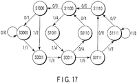
- a PRML method is utilized at the time of signal reproduction recorded at high density, and a signal processor circuit and a state transition chart shown in FIGS. 15 to 17 is used (A detailed description is given later).
- the embodiment is technically featured in that a value of Al 405 has been set so as to meet formulas (20) and (21).
- Formula (25) is a formula derived from a very coarse result of discussion, and is merely shown as a basic concept. Because the Ah 405 setting range is specified in accordance with formula (16), in the embodiment, at least a condition for Al 405 is mandatory as: Al 405 > 0.3
- a wavelength of ⁇ max write is shorter than a wavelength of reproduction light or recording/reproducing light (for example, 405 nm)
- the wavelength of ⁇ max write may be longer than a wavelength of reproduction light or recording/reproducing light (for example, 405 nm), without being limited thereto.
- the thickness Dg of the recording layer 3-2 is influenced. For example, if the thickness Dg of the recording layer 3-2 significantly exceeds an allowable value, optical characteristics of only a part coming into contact with the transparent substrate 2-2 in the recording layer 3-2 are changed as a state that follows forming of the recording mark 9, whereby the optical characteristics of a portion coming into contact with the light reflection layer 4-2 adjacent to its location are obtained as a value equal to that in the unrecorded area.
- the thickness Dg of the recording layer 3-2 significantly exceeds an allowable value, a temperature gradient occurs in the thickness direction in the recording layer 3-2 when the recording mark is formed. Then, before reaching the optical characteristic change temperature at a portion coming into contact with the light reflection layer 4-2 in the recording layer 3-2, a gasification (evaporation) temperature of a portion coming into contact with the transparent substrate 2-2 is exceeded or a thermal deformation temperature is exceeded in the transparent substrate 2-2.
- the thickness Dg of the recording layer 3-2 is set to "3T” or less based on the discussion of thermal analysis; and a condition meeting formula (23) is such that the thickness Dg of the recording layer 3-2 is set to "3 ⁇ 3T" or less.
- the thickness Dg of the recording layer 3-2 is equal to or smaller than "3T", although formula (22) can be met, the thickness may be set to "T” or less in consideration of effect of a tilt due to a facial motion or warping of the write-once type information storage medium or a margin relevant to a focal blurring.
- the thickness Dg of the recording layer 3-2 in the embodiment is set in the range assigned in a required minimum condition that: 9 ⁇ T ⁇ Dg ⁇ ⁇ / 8 ⁇ n 32 and in a desired condition that: 3 ⁇ T ⁇ Dg ⁇ ⁇ / 4 ⁇ n 32
- the severest condition can be defined as: T ⁇ Dg ⁇ ⁇ / 4 ⁇ n 32
- a value of the channel bit length T is 102 nm in the H format, and is 69 nm to 80 nm in the B format.
- a value of 3T is 306 nm in the H format and is 207 nm to 240 nm in the B format.
- a value of 9T is 918 nm in the H format and is 621 nm to 720 nm in the B format.
- H-L the conditions for formulas (27) to (29) can be applied to an "L-H” recording film without being limited thereto.
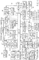
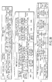
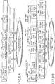
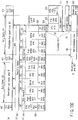
- FIG. 11 shows an illustration of a structure in an embodiment of an information recording/reproducing apparatus.
- an upper side of a control unit 143 mainly indicates an information recording control system for an information storage medium.
- a structure excluding the information recording control system in FIG. 11 corresponds to the above structure.
- the arrow drawn by the thick solid line indicates a flow of main information which designates a reproduction signal or a recording signal;
- the arrow of the thin solid line denotes a flow of information;
- the arrow of the one-dotted chain line denotes a reference clock line;
- the arrow of the thin dashed line denotes a command indicating direction.
- An optical head (not shown) is arranged in an information recording/reproducing unit 141 shown in FIG. 11 .
- a wavelength of a light source (semiconductor laser) used in the optical head is 405 nm
- the embodiment is not limited thereto, and there can be used a light source having a use wavelength equal to or shorter than 620 nm or 530 nm or a light source ranging from 355 nm to 455 nm, as described previously.
- two objective lenses used to focus the light beam having the above wavelength onto the information storage medium may be incorporated in the optical head.
- an objective lens having a NA value of 0.65 is used.
- an intensity distribution of incident light immediately before the light is incident to an objective lens the relative intensity at the periphery of the objective lens (at the boundary position of an aperture) when the center intensity is set to "1" is referred to as "RIM Intensity”.
- a value of the RIM intensity in the H format is set in the range of 55% to 70%.
- a wave surface aberration amount in the optical head is optically designed so as to be 0.33 ⁇ (0.33 ⁇ or less) with respect to a use wavelength ⁇ .
- a partial response maximum likelihood PRML is used for information reproduction to achieve high density of an information storage medium ( FIG. 1 , point [A]).
- PR(1, 2, 2, 2, 1) is used as a PR class to be used
- line density can be increased and the reliability of a reproduction signal can be improved (i.e., demodulation reliability can be improved) when a servo correction error such as a focal blurring or a track shift has occurred.
- PR(1, 2, 2, 2, 1) is employed ( FIG. 1 , point [A1]).
- a channel bit pattern after modulated is recorded in an information storage medium in accordance with a (d, k; m, n) modulation rule (In the above described method, this denotes RLL(d, k) of m/n modulation).
- ETM Average to Twelve Modulation
- a channel bit gap is reduced to the minimum.
- a partial response maximum likelihood (PRML) technique is used as a method for thus reproducing a recording mark or a pit, which has been dense up to the vicinity of a limit of the MTF characteristics (shutdown frequency).
- PRML partial response maximum likelihood
- a signal reproduced from the information recording/reproducing unit 141 receives reproducing waveform correction by a PR equalizer circuit 130.
- a signal having passed through the PR equalizer circuit 130 is sampled by converting a signal after passing through the PR equalizer circuit 130 to a digital amount in accordance with a timing of a reference clock 198 sent from a reference clock generating circuit 160; the sampled signal is converted to a digital data by an AD converter 169; and a Viterbi decoding process is carried out in a Viterbi decoder 156.
- the data after Viterbi-decoded is processed as data, which is completely similar to binary data at a conventional slice level.
- the information reproducing apparatus or information recording/reproducing apparatus has another sampling timing sampling circuit in particular (combination of Schmidt trigger binarizing circuit 155 and PLL circuit 174).
- This Schmidt trigger circuit 155 has a specific value (forward direction voltage value of diode in actuality) at a slice reference level for binarizing, and is featured in that binarizing is provide only when the specific width has been exceeded. Therefore, for example, as described above, in the case where a pattern of "1010101010101010101010” has been input, a signal amplitude is very small, and thus, switching of binarizing does not occur.
- an NRZI (Non Return to Zero Invert) technique is employed, and a position of "1" of the above pattern coincides with an edge section (boundary section) of a recording mark or a pit.
- a PLL circuit 174 detects a shift in frequency and phase between a binary signal which is an output of this Schmidt trigger binarizing circuit 155 and a signal of a reference clock 198 sent from a reference clock generating circuit 160 to change the frequency and phase of the output clock of the PLL circuit 174.
- a reference clock generating circuit 160 applies a feedback to (a frequency and a phase) of a reference clock 198 so as to lower an error rate after Viterbi decoded, by using an output signal of this PLL circuit 174 and decoding characteristic information on a Viterbi decoder 156 and a convergence length (information on (distance to convergence)) in a path metric memory in the Viterbi decoder 156, although is not specifically shown).
- the reference clock 198 generated by this reference clock generating circuit 160 is utilized as a reference timing at the time of reproduction signal processing.
- a sync code position sampling unit 145 serves to detect the presence and position of a sync code, which coexists in an output data train of the Viterbi decoder 156 and to sample a start position of the above output data.
- a demodulator circuit 152 carries out a demodulating process with respect to data temporarily stored in a shift resistor circuit 170.
- the above temporarily stored data is returned to its original bit pattern with reference to a conversion table recorded in a demodulating conversion table recording unit 154 on 12-channel bit by bit basis.
- an error correcting process is performed by an ECC decoding circuit 162, and descrambling is carried out by a descrambling circuit 159.
- Address information is recorded in advance by wobble modulation in a recording type (rewritable type or write-once type) information storage medium according to the embodiment.
- a wobble signal detecting unit 135 reproduces this address information (i.e., judges the contents of a wobble signal), and supplies information required to provide an access to a desired location to the control unit 143.
- an ECC block is formed by an ECC encoding circuit 161, and the ECC block is converted to a channel bit pattern by a modulating circuit 151.
- a sync code is added by a sync code generating/adding unit 146, and data is recorded in an information storage medium in the information recording/reproducing unit 141.
- DSV values after modulated are sequentially calculated by a DSV (Digital Sum Value) calculating unit 148, and the serially calculated values are fed back to code conversion after modulated.
- DSV Digital Sum Value
- FIG. 12 shows a detailed structure of peripheral portions including the sync code position detector unit 145 shown in FIG. 11 .
- a sync code is composed of a sync position detecting code section and a variable code section having a fixed pattern. From the channel bit pattern output from a Viterbi decoder, a sync position detecting code detector unit 182 detects a position of a sync position detecting code section having the above fixed pattern.
- Variable code transfer units 183 and 184 sample data on a variable code which exists before and after the detected position, and judge in which sync frame in a sector the sync code is positioned, the sync code being detected by an identifying unit 185 for detecting a sync position having the above fixed pattern.
- User information recorded on an information storage medium is sequentially transferred in order of a shift register circuit 170, a demodulation processing unit 188 in a demodulator circuit 152, and an ECC decoding circuit 162.
- the high density of the information storage medium is achieved (in particular, line density is improved) by using the PRML system for reproduction in a data area, a data lead-in area, and a data lead-out area.
- FIG. 13 shows an embodiment of a signal reproducing circuit using a slice level detecting system used at the time of reproduction in a system lead-in area and a system lead-out area.
- a quadrature optical detector 302 of the optical head device 101 in FIG. 13 is fixed into the optical head, which exists in the information recording/reproducing unit 141 in FIG. 11 .
- a signal having taken a sum of detection signals obtained from optical detecting cells 1a, 1b, 1c, and 1d of the quadrature optical detector 302 is referred to as a "lead channel 1 signal".
- a reproduction signal obtained from an information storage medium is subjected to a waveform equalizing process by a pre-equalizer 308 after the signal has passed through a high path filter 306 which shuts out a frequency component lower than a reproduction signal frequency bandwidth.
- this pre-equalizer 308 minimizes a circuit scale by using a 7-tap equalizer and can detect a reproduction signal precisely.
- the 7-tap equalizer is used.
- a VFO circuit/PLL 312 in FIG. 13 corresponds to the PLL circuit 174 in FIG. 11 ; and a demodulating/ECC decoding circuit 314 in FIG. 13 corresponding to the decoding circuit 152 and the ECC decoding circuit 162 in FIG. 11 .
- FIG. 14 shows a detailed structure in a circuit of the slicer 310 in FIG. 13 .
- a binary signal after sliced is generated by using a comparator 316.
- an inverting signal of binary data after binarized is set at a slice level at the time of binarizing.
- a cutoff frequency of this low path filter is set to 5 KHz.
- this cutoff frequency is high, a slice level change is fast, and the low path filter is affected by noise.
- a cutoff frequency is low, a slice level response is slow, and thus, the filter is affected by dust or scratch on the information storage medium.
- the cutoff frequency is set to 5 KHz in consideration of a relationship between RLL (1, 10) and a reference frequency of a channel bit described previously.
- FIG. 15 shows a signal processor circuit using a PRML detecting technique used for signal reproduction in a data area, a data lead-in area, and a data lead-out area.
- a quadrature optical detector 302 of the optical head device 111 in FIG. 15 is fixed into the optical head, which exists in the information recording/reproducing unit 141 in FIG. 11 .
- a signal having taken a sum of detection signals obtained from the optical detecting cells 1a, 1b, 1c, and 1d of the quadrature optical detector 302 is referred to as a "lead channel 1 signal".
- a derailed structure in the PR equalizer circuit 130 in FIG. 11 is composed of circuits from a preamplifier 304 to a tap controller 332, an equalizer 330, and an offset canceller 336 in FIG. 15 .
- a PLL circuit 334 in FIG. 15 is a part in the PR equalizer circuit 130, and denotes an element other than the Schmidt trigger binarizing circuit 155.
- a primary cutoff frequency of a high path filter circuit 306 in FIG. 15 is set at 1 KHz.
- a pare-equalizer circuit 308 uses a 7-tap equalizer in the same manner as that in FIG. 13 (because the use of the 7-tap equalizer minimizes a circuit scale and can detect a reproduction signal precisely).
- a sample clock frequency of an A/D converter circuit 324 is set to 72 MHz, and a digital output is produced as an eight-bit output.
- PRML detecting technique if a reproduction signal is affected by a level change (DC offset) of its entire signal, an error is likely to occur at the time of Viterbi demodulation.
- an adaptive equalizing process is carried out in the PR equalizer circuit 130.
- a tap controller for automatically correcting tap coefficients in the equalizer 330 is utilized by utilizing an output signal of the Viterbi decoder 156.
- FIG. 16 shows a structure in the Viterbi decoder 156 shown in FIG. 11 or 15 .
- a branch metric relevant to all branches, which can be predicted in response to an input signal, is calculated by a branch metric calculating unit 340, and the calculated value is sent to an ACS 342.
- the ACS 342 is an acronym of Add Compare Select, which calculates a path metric obtained by adding branch metrics in response to each of the passes which can be predicted in the ACS 342 and transfers the calculation result to a path metric memory 350.
- a calculating process is carried out with reference to the information contained in the path metric memory 350.
- a path memory 346 temporarily stores a value of the path metric corresponding to each path (transition) state and such each path, which can be predicted in the memory 346, the value being calculated by the ACS 342.
- An output switch unit 348 compares a path metric corresponding to each path, and selects a path when a path metric value becomes minimal.
- FIG. 17 shows a state change in PR(1, 2, 2, 2, 1) class in the embodiment.
- a change of a state which can be obtained in the PR(1, 2, 2, 2, 1) class can be made as only a change shown in FIG. 17 , and a path which can exist (which can be predicted) at the time of decoding is identified in the Viterbi decoder 156 based on a transition chart in FIG. 17 .
- the exposure levels at the time of recording have four levels of recording power (peak power), bias power 1, bias power 2, and bias power 3.
- peak power the level of recording power
- bias power 1 the level of recording power
- bias power 2 the level of bias power 3
- bias power 3 the level of bias power 3.
- a minimum mark length relevant to a channel bit length T is obtained as 2T.
- this minimum mark of 2T is recorded, one write pulse of recording power (peak power) after bias power 1 is used as shown in FIG. 18 , and bias power 2 is temporarily obtained immediately after the write pulse.
- bias power 2 is temporarily used after exposing two write pulses, a first pulse and a last pulse of recording power (peak power) level that follows bias power 1.
- bias power 2 is used after multi-pulse and write pulse exposure.
- the vertical dashed line in FIG. 18 shows a channel clock cycle.
- the laser power is risen at a position delayed by T SFP from a clock edge, and fallen at a position, which is backward by T ELP from an edge of a succeeding clock.
- a cycle during which the laser power is set at bias power 2 is defined as T LC .
- T SFP , T ELP , and T LC are recorded in physical format information PFI contained in a control data zone CDZ as described later in the case of the H format.
- the laser power is risen at a position delayed by T SFP from a clock edge, and lastly, ended with a last pulse.
- T SLP Shift times from a clock edge to a rise/fall timing of the last pulse
- T ELP Shift times from a clock edge to a rise/fall timing of the last pulse
- T EFP a shift time from a clock edge to a fall timing of the last pulse
- T MP an interval of a single pulse of a multi-pulse
- Each of intervals T ELP - T SFP , T MP , T ELP - T SLP , and T LC is defined as a half-value wide relevant to a maximum value, as shown in FIG. 19 .
- the above parameter setting range is defined as follows: 0.25 ⁇ T ⁇ T SFP ⁇ 1.50 ⁇ T 0.00 ⁇ T ⁇ T ELP ⁇ 1.00 ⁇ T 1.00 ⁇ T ⁇ T EFP ⁇ 1.75 ⁇ T - 0.10 ⁇ T ⁇ T SLP ⁇ 1.00 ⁇ T 0.00 ⁇ T ⁇ T LC ⁇ 1.00 ⁇ T 0.15 ⁇ T ⁇ T MP ⁇ 0.75 ⁇ T
- the values of the above described parameters can be changed as shown in FIGS. 20A, 20B and 20C according to a recording mark length (Mark Length) and the immediately preceding/immediately succeeding space length (Leading/Trailing space length).
- FIGS. 21A, 21B and 21C each shows parameter values when optimal recording power of the write-once type information storage medium recorded in a principle of recording shown in the embodiment has been checked, as described in the section "3-3) Recording characteristics common to organic dye recording film in the embodiment".
- the values of bias power 1, bias power 2, and bias power 3 are 2.6 mW, 1.7 mW, and 1.7 mW, and reproduction power is 0.4 mW.
- the "L-H" recording film is featured in that the reflection amount range in an unrecorded location and a recorded location has been specified in view of characteristics of a read-only type information storage medium having a one-sided two-layered structure.
- FIG. 22 shows a light reflection factor range in an unrecorded area (non-recording portion) of the "H-L” recording film and the "L-H” recording film according to the embodiment.
- the lower limit value ⁇ of the reflection factor at the non-recording portion of the "H-L” recording film is specified so as to be higher than an upper limit value ⁇ at the non-recording portion of the "L-H” recording film.
- the lower limit value ⁇ of the light reflection factor of the non-recording portion ("L" portion) of the "L-H” recording film is set to 18%, and the upper limit value ⁇ is set to 32%; and the lower limit value ⁇ of the light reflection factor of the non-recording portion ("H" portion) of the "H-L” recording film is set to 40%, and the upper limit value ⁇ is set to 85%.
- FIGS. 23 and 24 show reflection factors at a non-recording position and a recorded position in a variety of recording films in the embodiment.
- an optical reflection factor range at the non-recording portion is specified as shown in FIG. 22 , whereby a signal appears in a same direction in an emboss area (such as system leas-in area SYLDI) and a recording mark area (data lead-in area DTLDI, data lead-out area DTLDO, or data area DTA) in the "L-H" recording film while a groove level is defined as a reference.
- an emboss area such as system leas-in area SYLDI
- a recording mark area data lead-in area DTLDI, data lead-out area DTLDO, or data area DTA
- a signal appears in an opposite direction in an emboss area (such as system lead-in area SYSDI) and a recording mark area (data lead-in area DTLDI, data lead-out area DTLDO, or data area DTA).
- SYSDI system lead-in area
- DTLDI data lead-in area
- DTLDO data lead-out area
- DTA data area
- reproduction signal characteristics obtained from a recording mark recorded on the "L-H” recording film shown in the embodiment is adjusted to conform to signal characteristics obtained from the "H-L” recording film to meet formulas (20) to (23).
- the same signal processor circuit can be used, and the signal processor circuit can be simplified and reduced in price.
- the relative absorbance in an unrecorded area is basically low in the "H-L” recording film, and thus, when reproduction light has been irradiated at the time of reproduction, there occurs an optical characteristic change generated by absorbing energy of the reproduction light.
- the "L-H” recording film has optical characteristics that "a light reflection factor of an unrecorded portion is lower than that in a recording mark". This means that, as is evident from the contents described with respect to FIG. 2B , the absorbance of the unrecorded portion is higher than that in the recording mark.
- the embodiment is featured in that, in the "L-H" recording film, a value of ⁇ max write (maximum absorption wavelength which is the closest to wavelength of recording light) is longer than a wavelength of recording light or reproduction light (close to 405 nm). In this manner, the absorbance relevant to the ultraviolet ray can be reduced, and the durability relevant to ultraviolet ray irradiation can be significantly improved.
- a difference in absorbance between a recorded portion and an unrecorded portion in the vicinity of ⁇ max write is small, and a degree of reproduction signal modulation (signal amplitude) in the case where the wavelength light in the vicinity of ⁇ max write is reduced.
- a design of a recording film 3-2 is made so that a wavelength of ⁇ max write exists out of the range of 355 nm to 455 nm (i.e., at a longer wavelength than 455 nm).
- FIG. 25 shows an example of light absorption spectra in the "L-H" recording film in the embodiment.
- a lower limit value ⁇ of a light reflection factor at a non-recording portion ("L" section) of the "L-H” recording film is set to 18%, and an upper limit value ⁇ is set to 32% in the embodiment.
- the light reflection factor at 405 nm of the light reflection layer 4-2 in FIGS. 2A and 2B is slightly lowered than 100%, it is assumed that the factor is almost close to 100% for the sake of simplification.
- the light reflection factor of the whole recording film at a wavelength of ⁇ max write is designated by R ⁇ max write .
- formula (36) is derived.
- the factor is not set to "0", and thus, it is necessary to drive a severer formula.
- a severe conditional formula for setting the upper light value ⁇ of the light reflection factor of the non-recording portion '"L" portion) of the "L-H" recording film to 32% is given by: 1 - Al 405 ⁇ 1 - R ⁇ max write ⁇ 0.32
- Al 355 ⁇ 40 % Al 455 ⁇ 40 % it is possible to ensure stable recording characteristics or reproduction characteristics even if a wavelength of a light source is changed in the range of 355 nm to 405 nm or in the range of 405 nm to 455 nm (in the range of 355 nm to 455 nm in the case where both of the formulas are met at the same time).
- FIG. 26 shows a light absorption spectrum change after recorded in the "L-H" recording film according to the embodiment. It is considered that a value of a maximum absorption wavelength ⁇ I max in a recording mark deviates from a wavelength of ⁇ max write , and an inter-molecular array change (for example, an array change between azo metal complexes) occurs.
- a discoloring action (cutting of local electron orbit (local molecular link dissociation)) occurs in parallel to a location in which both of the absorbance in location of ⁇ l max and the absorbance Al 405 at 405 nm are lowered and the light absorption spectra spreads itself.
- a lower limit value ⁇ of a light reflection factor of an unrecorded portion ("L" portion) of an "L-H” recording film is set to 18%, and this value corresponds to I 11L .
- the thickness of the recording layer 3-2 meets the conditions shown in formulas (3), (4), (27), and (28), and is formed by spinner coating (spin coating).
- spinner coating spin coating
- a crystal of a "salt” is assembled by “ion coupling” between positively charged “sodium ions” and negatively charged “chloride ions”.
- a plurality of polymers are combined with each other in the form close to “ion coupling", forming configuring an organic dye material.
- the organic dye recording film 3-2 in the embodiment is composed of a positively charged "cation portion" and a negatively charged "anion portion”.
- the above recording film is technically featured in that: coupling stability is improved by utilizing a “dye” having chromogenic characteristics for the positively charged “cation portion” and utilizing an organic metal complex for the negatively charged “anion portion”; and there is met a condition that "an electron structure in a chromogenic area is stabilized, and structural decomposition relevant to ultraviolet ray or reproduction light irradiation hardly occurs” shown in "Basic feature common to organic dye recording material in the embodiment".
- an "azo metal complex" whose general structural formula is shown in FIG. 3 is utilized as an organic metal complex.
- cobalt or nickel is used as a center metal M of this azo metal complex, thereby enhancing optical stability.
- a dye used for the cation portion there is used any of a cyanine dye whose general structural formula is shown in FIG. 27 ; a styril dye whose general structural formula is shown in FIG. 28 ; and a monomethine cyanine dye whose general structural formula is shown in FIG. 29 .
- a formazane metal complex whose general structural formula is shown in FIG. 30 may be used without being limited thereto, for example.
- the organic dye recording material comprising the anion portion and cation portion is first powdered.
- the powdered organic dye recoding material is dissolved in organic solvent, and spin coating is carried out on the transparent substrate 2-2.
- the organic solvent to be used includes: a fluorine alcohol based TFP (tetrafluoro propanol) or pentane; hexane; cyclohexane; petroleum ether; ether or analogous, nitrile or analogous, and any of a nitro compound or sulfur-containing compound or a combination thereof.
- a fluorine alcohol based TFP tetrafluoro propanol
- pentane hexane
- cyclohexane cyclohexane
- petroleum ether ether or analogous, nitrile or analogous, and any of a nitro compound or sulfur-containing compound or a combination thereof.
- the embodiment assumes a range of 355 nm to 455 nm in particular around 405 nm.
- the metal materials each having a high light reflection factor at this wavelength bandwidth are arranged in order from the highest light reflection factor, Ag is in the order of around 96%; Al is in the order of around 80%, and Rh is in the order of around 80%.
- the reflection light from the light reflection layer 4-2 is a standard, and thus, the light reflection layer 4-2 requires a high light reflection factor in characteristics.
- the light reflection factor in an unrecorded area is low.
- a reproduction signal C/N ratio from a pre-pit (emboss) area is low, lacking the stability at the time of reproduction.
- the light reflection factor in the light reflection layer 4-2 simplex is high. Therefore, in the embodiments, in the above wavelength bandwidth, a material mainly made of Ag (silver) having the highest reflection factor is used.
- the light reflection layer 4-2 As a material for the light reflection layer 4-2, there occurs a problem that "atoms easily move” or “corrosion easily occurs” if silver is used alone.
- the light reflection layer 4-2 is made of AgNdCu according to the first embodiment. AgNdCu is in a solid soluble state, and thus, the reflection factor is slightly lowered than a state in which silver is used alone.
- the light reflection layer 4-2 is made of AgPd, and an electric potential is changed, whereby corrosion hardly occurs in an electrochemical manner. If the light reflection layer 4-2 corrodes due to silver oxidization or the like, the light reflection factor is lowered.
- an organic dye recording film having a recording film structure shown in FIG. 2B in particular, in the case of an organic dye recording film shown in "Characteristics of Organic Dye Recording Film in the Present Embodiment", in particular, a light reflection factor on an interface between the recording layer 3-2 and the light reflection later 4-2 is very important. If correction occurs on this interface, the light reflection factor is lowered, and an optical interface shape blurs.
- the detection signal characteristics from a track shift detection signal (push-pull signal) or a wobble signal and a pre-pit (emboss) area are degraded.
- a track shift detection signal (push-pull signal) or a wobble signal is hardly generated, thus increasing effect of degradation of the light reflection factor on the interface between the recording layer 3-2 and the light reflection layer 4-2 due to corrosion.
- AgBi is used for the light reflection layer 4-2 as the third embodiment.
- AgBi forms a very stable phase and prevents degradation of the light reflection factor on the above interface because a passive coat film is formed on a surface (interface between the recording layer 3-2 and the light reflection layer 4-2).
- Bi bismuth
- Bi bismuth
- oxidized bismuth a very fine film (passive coat film) called oxidized bismuth is formed to function to preclude internal oxidization.
- This passive coat film is formed on the interface, and forms a very stable phase.
- the degradation of a light reflection factor does not occur, and the stability of detection signal characteristics from a track shift detection signal (push-pull signal) or a wobble signal and a pre-pit (emboss) area is guaranteed over a long period of time.
- the silver simplex has the highest light reflection factor, and the light reflection factor is lowered as an additive amount of other atoms is increased.
- an additive amount of Bi atoms in AgBi in the embodiment be equal to or smaller than 5 at%.
- the unit of at% used here denotes atomic percent, and indicates that five Bi atoms exist in a total atom number 100 of AgBi, for example.
- an additive amount of Bi atoms in the light reflection layer 4-2 in the embodiment is defined as 1 at%.
- a detection signal can be stably obtained from a track shift detection signal (push-pull signal) or a wobble signal and a pre-pit (emboss) area with high precision.
- the third embodiment is not limited to AgBi, and a ternary system including AgMg, AgNi, AgGa, AgNx, AgCo, AgAl or the atoms described previously may be used as a silver allow which produces a passive coat film.
- the thickness of this light reflection layer 4-2 is set in the range of 5 nm to 200 nm. If the thickness is smaller than 5 nm, the light reflection layer 4-2 is not uniform, and is formed in a land shape.
- the thickness of the light reflection layer 4-2 is set to 5 nm.
- the thickness is set in the range of 80 nm to 200 nm, and preferably, in the range of 100 nm to 150 nm.
- the thickness is set in the range of 5 nm to 15 nm.
- the system lead-in area SYLDI is provided in an H format according to the embodiment.
- an emboss pit area 211 is provided in this area, and, as shown in FIGS. 71A ((? 5A ?)) and 71B ((? 5B ?)), information is recorded in advance in the form of a pre-bit.
- a reproduction signal in this area is adjusted to conform to reproduction signal characteristics from a read-only type information storage medium, and a signal processor circuit in an information reproducing apparatus or an information recording/reproducing apparatus shown in FIG. 11 is compatible with a read-only type information storage medium and a write-once type information storage medium.
- the reproduction signal in this area is set to be: I 11 ⁇ H / I 11 ⁇ H ⁇ 0.3 and desirably, is set to be: I 11 / I 11 ⁇ H > 0.5
- the amplitude is set to be: I 2 / I 11 ⁇ 0.5 and desirably, is set to be: I 2 / I 11 > 0.7
- the reproduction signal amplitude value I 11 is determined depending on a step amount Hpr between the space area 14 and the pre-pit (emboss) area 13 in the light reflection layer 4-2.
- this step amount Hpr with respect to a reproduction light wavelength ⁇ and a refractive index n 32 in the recording layer 3-2, has the following relationship: I 11 ⁇ sin 2 2 ⁇ ⁇ ⁇ Hpr ⁇ n 32 ⁇ ⁇
- the thickness of the recording layer 3-2 is small in the space area 14, and thus, a step on an interface between the light reflection layer 4-2 and the recording layer 3-2 is small, and formula (62) has not successfully met.
- a contrivance has been made to ensure that a relationship between the thickness Dg of the recording layer 3-2 in the pre-pit (emboss) area 13 and the thickness Dl of the recording layer 3-2 in the space area 14 conform with a condition described in "characteristics relating to thickness distribution of recording layer in the embodiment for definition of parameters".
- a sufficiently large step Hpr which meets formula (62) or formula (63) has been successfully provided.
- FIG. 31 shows a structure and dimensions of an information storage medium in the embodiment.
- the above three types of information storage mediums are common to each other in a majority of structure and dimensions.
- a burst cutting area BCA a burst cutting area BCA, a system lead-in area SYLDI, a connection area CNA, a data lead-in area DTLSI, and a data area DTA have been arranged.
- All the mediums other than an OPT type read-only medium is featured in that a data lead-out area DTLDO is arranged at the outer periphery. As described later, in the OPT type read-only medium, a middle area MDA is arranged at the outer periphery. In either of the write-once type and rewritable type mediums, the inside of this area is for read-only (additional writing disabled).
- high density of the information storage medium is achieved (in particular, line density is improved) by using a PRML (Partial Response Maximum Likelihood) method for reproduction of signals recorded therein.
- PRML Partial Response Maximum Likelihood
- the burst cutting area BCA and system lead-in area SYLDI are separated from each other in location without being superimposed on each other. These areas are physically separated from each other, thereby making it possible to prevent interference between the information recorded in the system lead-in area SYLDI at the time of information reproduction and the information recorded in the burst cutting area BCA and to allocate information reproduction with high precision.
- the following signal characteristics of the burst cutting area BCA are defined between a radius 22.4 mm and a radius 23.0.
- a waveform shown in FIG. 70A can be obtained.
- the maximum and minimum levels when a BCA code and a channel bit are set to "0" are defined as "IBHmax” and "IBHmin”, and the maximum bottom level when the BCA code and channel bit are set to "1" is defined as "IBLmax”.
- an intermediate level is defined as "(IBHmin + IBLmax)/2".
- detection signal characteristics are defined as a condition that (IBLmax/IBHmin) is equal to or smaller than 0.8 and as a condition that (1BHmax/IBHmin) is equal to or smaller than 1.4.
- Cyclic signals of the BCA code and channel bit are shown in FIG. 70B . While an average level between IBL and IBH is defined as a reference, an edge position is regarded at a position at which the BCA signal crosses the reference position.
- a cycle of the BCA signal is defined when a rotation speed is 2760 rpm (46.0 Hz). As shown in FIG. 70B , a cycle between starting edges (fall positions) is defined as 4.63 ⁇ n ⁇ 1.00 ⁇ s, and a width of a pulse position in a place where a light amount is lowered (a gap from a fall position to a next rise position) is defined as 1.56 ⁇ 0.75 ⁇ s.
- the BCA code is often recorded after manufacture of an information storage medium has terminated.
- the BCA code may be recorded in advance as a pre-pit.
- the BCA code is recorded in a direction along a circumference of the information storage medium, and a direction in which the pulse width is narrow is recorded so as to be coincident with a direction in which a light reflectance is low.
- the BCA code is recorded after demodulated in accordance with an RZ modulating method.
- a BCA data structure is shown in FIG. 71 .
- BCA data has two BCA pre-ambles 73 and 74, two postambles 76 and 77, and two BCA data areas BCAA.
- a BCA error detection code EDC BCA and a BCA error correction code FCC BCA are added to each of the BCA data areas BCAA, and a BCA connection area 75 is allocated therebetween.
- a sync byte SB BCA or re-sync RS BCA of one by one bytes is inserted on a 4 by 4 bytes basis.
- the BCA preambles 73 and 74 each are composed of 4 bytes, and all "00h" are recorded.
- the sync byte SB BCA is allocated immediately preceding each of the BCA preambles 73 and 74.
- the BCA postambles 76 and 77 each are composed of 4 bytes, and all repetition patterns of "55h” are recorded.
- the BCA connection area 75 is composed of 4 bytes, and all "AAh” are repeatedly recorded.
- Bit patterns of the BCA sync byte SB BCA and BCA re-sync RS BCA are shown in FIG. 72 .
- a fixed pattern 67 is obtained in the case of mode A while a sync code 68 is obtained in the case of mode B.
- FIG. 73 shows exemplary BCA information contents recorded in the BCA data area.
- 76-byte information can be recorded in the BCA data area BCAA, and data is recorded in units of BCA record unit BCAU.
- BCA record Information to be recorded in the BCA record unit (BCAU) is called a BCA record.
- the size of each BCA record is an integer multiple of 4 bytes.
- each BCA record a BCA record ID 61 composed of 2 bytes, version number information 62 composed of 1 byte, data length information 63 of recorded data, the information being composed of 1 byte, and a data record of 4m bytes (recording data 64) are sequentially recorded as shown in (c) of FIG. 73 .
- ID set to the BCA record ID 61 As ID set to the BCA record ID 61, from 0000h to 7FFFFh are assigned to a formula utilization method, and from 80000h to FFFFh are assigned to an individual utilization method.
- the version number information 62 composed of 1 byte is divided into major number 71 of the significant 4 bits and minor number 72 of the least significant 4 bits.
- a first integer digit of version number is recorded.
- the minor number 72 a value of a first digit after a decimal point of version number is recorded. In the case of, for example, version "2.4", number “2" is recorded in a field of the major number 71, and number "4" is recorded in a field of the minor number 72.
- identification information 80 of an HD_DVD specification type is recorded in the BCA record, as shown in (e) of FIG. 73 .
- a BCA record ID 81, version number information 82, and data length information 83 of recorded data are recorded, and moreover, specification type information 84 composed of 4 bites, disk type information 85 composed of 4 bits, extended part version information 86 (1 byte), and a reserved area 87 (2 bytes) are recorded, as shown in (f) of FIG. 73 .
- Information 88 of polarity of a recording mark (identification of H ⁇ L or L ⁇ H) is allocated in the significant 1 bit contained in the disk type information 85.
- the BCA error correction code FCC BCA exists in addition to the conventionally existing BCA error detection code EDC BCA . Consequently, even if an error occurs with the data contained in the BCA data area BCAA, such an error can be corrected by the BCA error correction code ECC BCA , and reliability is further improved.
- Data (barcode data) to be recorded in the burst cutting area BCA is formed by locally exposing a recording film with laser.
- Data recorded in the burst cutting area BCA is formed by locally carrying out laser exposure to a recording film.
- the system lead-in area SYLD1 is formed of the emboss bit area 211, and thus, the reproduction signal from the system lead-in area SYLDI appears in a direction in which a light reflection amount decreases as compared with a light reflection level from the mirror surface 210. If while the burst cutting area BCA is formed as the mirror surface 210, in the case where the "L-H" recording film has been used, a reproduction signal from the data recorded in the burst cutting area BCA appears in a direction in which a light reflection amount increases more significantly than a light reflection level from the mirror surface 210 (in an unrecorded state).
- an information reproducing apparatus or an information recording/reproducing apparatus carry out processing in accordance with the steps of:
- the present embodiment is featured in that fine irregularities are formed in advance in thus burst cutting area BCA.
- the light reflection level becomes lower than that from the mirror surface 210 due to a light interference effect at the stage prior to recording data (barcode data) by local laser exposure. Then, there is attained an advantageous effect that a step is remarkably decreased between a reproduction signal amplitude level (detection level) from the data formed in the burst cutting area BCA and a reproduction signal amplitude level (detection level) from the system lead-in area SYLDI; the reliability of information reproduction is improved; and processing going from the above item 1) to item 2) is facilitated.
- the specific contents of fine irregularities formed in advance in the burst cutting area BCA include the emboss pit area 211 like the system lead-in area SYLDI.
- Another embodiment includes a method for forming the groove area 214 or the land area and the groove area 213 like the data lead-in area DTLDI or data area DTA.
- the track pitches of the groove area 214 or the land area and groove area 213 formed in the burst cutting area BCA are adjusted to conform with those of the emboss pits in the system lead-in area SYLDI, thereby making it possible to continuously maintain a constant motor speed in the burst cutting area BCA and the system lead-in area SYLDI.
- FIG. 32 shows parameter values according to the present embodiment in a read-only type information storage medium
- FIG. 33 shows parameter values according to the present embodiment in a write-once type information storage medium
- FIG. 34 shows parameter values according to the present embodiment in a rewritable type information storage medium.
- the rewritable type information storage medium has higher recording capacity than the read-only type or write-once type information storage medium by narrowing track pitches and line density (data bit length).
- the track pitches are narrowed by reducing effect of a cross-talk of the adjacent tracks by employing land-groove recording.
- any of the read-only type information storage medium, write-once information storage medium, and rewritable-type information storage medium is featured in that the data bit length and track pitches (corresponding to recording density) of the system lead-in/system lead-out areas SYLDT/SYLDO are greater than those of the data lead-in/data lead-out area DTLDI/DTLDO (in that the recording density is low).
- the data bit length and track pitches of the system lead-in/system lead-out areas SYLDI/SYLDO are close to the values of the current DVD lead-in area, thereby realizing compatibility with the current DVD.
- an emboss step in the system Lead-in/system lead-out areas SYLDI/SYLDO of the write-once type information storage medium is shallowly defined.
- the data bit length (and track pitches) of system lead-in/system lead-out areas SYLDI/SYLDO are roughened and a repetition frequency of pits and spaces at the narrowest position is isolated (significantly reduced) from an optical shutdown frequency of an MTF (Modulation Transfer Function) of a reproduction objective lens, thereby making it possible to increase the reproduction signal amplitude from the system lead-in/system lead-out areas SYLDI/SYLDO and to stabilize reproduction.
- MTF Modulation Transfer Function
- FIGS. 35A, 35B and 35C show a comparison of detailed data structure in a system lead-in area SYLDI and a data lead-in area DTLDI in a variety of information storage mediums.
- FIG. 35A shows a data structure of a read-only type information storage medium
- FIG. 35B shows a data structure of a rewritable-type information storage medium
- FIG. 35C shows a data structure of a write-once type information storage medium.
- the read-only type information storage medium is featured in that the emboss pit area 211 having emboss pits formed therein is provided in all of the system lead-in area SYLDI and data lead-in area DTLDI and data area DTA.
- the emboss pit area 211 is provided in the system lead-in area SYLDI, and the connection zone CNZ is provided in the mirror surface 210.
- the rewritable-type information storage medium is featured in that the land area and the groove area 213 are formed in the data lead-in area DTLSI and the data area DTA.
- the write-once type information storage medium is featured in that the groove area 214 is formed in the data lead-in area DTLDI and the data area DTA. Information is recorded by forming a recording mark in the land area and the groove area 213 or groove area 214.
- the initial zone INZ indicates a start position of the system lead-in area SYLDI.
- data ID Identification Data
- one physical sector records information on a data frame structure composed of data ID, IED (ID Error Detection code), main data for recording user information, and EDC (Error detection code); and the initial zone records information on the above described data frame structure.
- IED ID Error Detection code
- EDC Error detection code
- a current location can be recognized from the information on physical sector numbers or logical sector numbers recorded therein. That is, when an information recording/reproducing unit 141 shown in FIG. 11 starts information reproduction from an information storage medium, in the case where reproduction has been started from the information contained in the initial zone INZ, first, the information on physical sector numbers or logical sector numbers recorded in the data ID information is sampled, and the sampled information is moved to the control data zone CDZ while the current location in the information storage medium is checked.
- a buffer zone 1 BFZ1 and a buffer zone 2 BFZ2 each are composed of 32 ECC blocks. As shown in FIGS. 32 , 33 and 34 , one ECC block corresponds to 1024 physical sectors. In the buffer zone 1 BFZ1 and the buffer zone 2 BFZ2 as well, like the initial zone INZ, main data information is set to all "00h".
- connection zone CNZ which exists in a CNA (Connection Area) is an area for physically separating the system lead-in area SYLDI and the data lead-in area DTLDI from each other. This area is provided as a mirror surface on which no emboss pit or pre-groove exists.
- An RCZ (Reference code zone) of the read-only type information storage medium and the write-once type information storage medium each is an area used for reproduction circuit tuning of a reproducing apparatus (for automatic adjustment of tap coefficient values at the time of adaptive equalization carried out in the tap controller 332 shown in FIG. 15 ), wherein information on the data frame structure described previously is recorded.
- the present embodiment is featured in that the RCZ (Reference code zone) of the read-only type information storage medium and the write-once information storage medium each is arranged adjacent to a DTA (data area).
- a control data zone is arranged between the reference code zone and data area, and the reference code zone and the data area are separated from each other.
- GTZ1 and GTZ2 are areas for specifying the start boundary position of the data lead-in area DTLDI, and a boundary position of a drive test zone DRTZ and a disc test zone DKTZ.
- guard track zone 1 GTZ1 and guard track zone 2 GTZ2 exist in the data lead-in area DTLDI, and thus, in this area, the write-once type information storage medium is featured in that the pre-groove area is formed in advance.
- the rewritable-type information storage medium is featured in that the groove area and the land area are formed in advance.
- the pre-groove area or groove area and the land area as shown in FIGS. 32 , 33 and 34 , wobble addresses are recorded in advance, and thus, the current location in the information storage medium is determined by using these wobble addresses.
- the disk test zone DKTZ is an area provided for manufactures of information storage mediums to carry out quality test (evaluation).
- the drive test zone DRTZ is provided as an area for carrying out test writing before the information recording/reproducing apparatus records information in the information storage medium.
- the information recording/reproducing apparatus carries out test writing in advance in this area, and identifies an optimal recording condition (write strategy). Then, the information contained in the data area DTA can be recorded under the optimal recording condition.
- the information recorded in the disk identification zone DIZ which exists in the rewritable-type information storage medium is an optional information recording area, the area being adopted to additionally write a set of drive descriptions composed of: information on manufacturer name of recording/reproducing apparatuses; additional information relating thereto; and an area in which recording can be uniquely carried out by the manufacturers.
- a defect management area 1 DMA1 and a defect management area 2 DMA2 which exist in a rewritable-type information storage medium record defect management information contained in the data area DTA, and, for example, substitute site information when a defect occurs or the like is recorded.
- the recording management zone RMZ records RMD (recording management data) which is an item of management information relating to a recording position of data updated by additional writing of data.
- a recording management zone RMZ is set for each bordered area BRDA, enabling area expansion of the recording management zone RMZ.
- the recording management zone RMZ is arranged in a border-in BRDI which corresponds to each bordered area BRDA (arranged immediately before each bordered area BRDA).
- the border-in BRDI corresponding to the first bordered area DRDA#1 and a data lead-in area DTLDI. are made compatible with each other, and efficient use of the data area DTA is promoted while the forming of the first border-in BRDI in the data area DTA is eliminated.
- the recording management zone RMZ in the data lead-in area DTA shown in FIG. 35C is utilized as a recording location of the recording management data RDM which corresponds to the first bordered area BRDA#1.
- the RMD duplication zone RDZ is a location for recording information on the recording management data RMD which meets the following condition in the recording management zone RMZ, and the reliability of the recording management data RMD is improved by providing the recording management data RMD in a duplicate manner, as in the present embodiment.
- the recording management data RMD contained in the recording management zone RMZ is valid due to dust or scratch adhering to a write-once information storage medium surface
- the recording management data RMD is reproduced, the data being recorded in this RMD duplication zone RDZ.
- the remaining required information is acquired by tracing, whereby information on the latest recording management data RMD can be restored.
- This RMD duplication zone records recording management data RDM at a time point at which (a plurality of) borders are closed. As described later, a new recording management zone RMZ is defined every time one border is closed and a next new bordered area is set. Thus, every time a new recording management zone RMZ is created, the last recording management data RMD relating to the preceding bordered area may be recorded in this RMD duplication zone RDZ.
- the RMD duplication zone RDZ becomes full with a comparatively small additional recording count, and thus, an upper limit value of the additional writing count becomes small.
- a location of the bordered area BRDA, which has been already closed, can be identified by reading the recording management data RMD lastly recorded in this RMD duplication zone RDZ.
- the location of the bordered area BRDA on the way of additional writing (before closed) and the contents of information recorded therein can be acquired by tracing another location in the data area DTA of the information storage medium, and the information on the latest recording management data RMD can be restored.
- An R physical information zone R-PFIZ records the information analogous to the physical format PFI contained in the control data zone CDZ which exists common to FIGS. 35A to 35C (described later in detail).
- FIG. 36 shows a data structure in the RMD duplication zone RDZ and the recording management zone RMZ which exists in the write-once type information storage medium ( FIG. 35C ).
- FIG. 36 (a) shows the same structure as that shown in FIG. 35C
- FIG. 36 (b) shows an enlarged view of the RMD duplication zone RDZ and the recording management zone RDZ shown in FIG. 35C .
- the RMD Recording Management Data
- RMD Recording Management Data
- FIG. 36 (b) a change has occurred with management data in location recording management data RMD#1 and RMD#2 has been recorded.
- this figure shows an example in which the data after changed (after updated) has been recorded as recording management data RMD#3 immediately after the recording management data RMD#2. Therefore, in the recording management zone RMD, a reserved area 273 exists so that additional writing can be further carried out.
- FIG. 36 (b) shows a structure in the recording management zone RMZ which exists in the data lead-in area DTLDI
- a structure in the recording management zone RMZ (or expanded recording management zone: referred to as expanded RMZ) which exists in the border-in BRDI or bordered area BRDA described later is also identical to the structure shown in FIG. 36 (b) without being limited thereto.
- the above processing method is not limited to the recording management zone RMZ contained in the data lead-in area DTLDI.
- a processing operation for padding all the reserved area 273 shown in FIG. 36 (b) with the latest recording management data RMD is carried out.
- the RMD duplication zone RDZ is divided into the RDZ lead-in area RDZLI and a recording area 271 of the last recording management data RMD duplication zone RDZ of the corresponding RMZ.
- the RDZ lead-in area RDZLI is composed of a system reserved field SRSF whose data size is 48 KB and a unique ID field UIDF whose data size is 16 KB, as shown in FIG. 36 (b) . All "00h" are set in the system reserved field SRSF.
- the present embodiment is featured in that DRZ lead-in area RDZLI is recorded in the data lead-in area DTLDI which can be additionally written.
- the medium is shipped with the RDZ lead-in area RDZLI being in an unrecorded state immediately after manufacturing.
- RDZ lead-in area RDZLI information is recorded.
- the present embodiment is secondarily featured in that the RMD duplication zone RDZ is provided at the inner periphery side than the recording management zone RMZ which corresponds to a first bordered area BRDA, and the RDZ lead-in RDZLI is arranged in the RMD duplication zone RDZ.
- the use efficiency of information acquisition is improved by arranging information (RDZ lead-in area RDZLI) representing whether or not the write-once type information storage medium is in a state immediately after manufacturing/shipment or has been used at least once in the RMD duplication zone RDZ used for the purpose of a common use (improvement of reliability of RMD).
- information RDZ lead-in area RDZLI
- the RDZ lead-in area RDZLI is arranged at the inner periphery side than the recording management zone RMZ, thereby making it possible to reduce a time required for acquisition of required information.
- the information recording/reproducing apparatus starts reproduction from the burst cutting area BCA arranged at the innermost periphery side, as described in FIG. 31 , and sequentially changes a reproducing location from the system lead-in SYLSI to the data lead-in area DTLDI while the reproduction position is sequentially moved to the innermost periphery side.
- a unique ID area UIDF records information relating to an information recording/reproducing apparatus for which the write-once type information storage medium immediately after shipment has been first used (i.e., for which recording has been first started).
- this area records a drive manufacturer ID 281 of the information recording/reproducing apparatus or serial number 283 and model number 284 of the information recording/reproducing apparatus.
- the unique ID area UIDF repeatedly records the same information for 2 KB (strictly, 2048 bytes) shown in FIG. 36 (c) .
- Information contained in the unique disk ID 287 records year information 293, month information 294, date information 295, time information 296, minutes information 297, and seconds information 298 when the storage medium has been first used (recording has been first started).
- a data type of respective items of information is described in HEX, BIN, ASCII as described in FIG. 36 (d) , and two types or four bytes are used.
- the present embodiment is featured in that the size of an area of this RDZ lead-in area RDZLI and the size of the one recording management data RMD are 64 KB, i.e., the user data size in one ECC block becomes an integer multiple.
- the size of the area of the RDZ lead-in area RDZLI and the size of such one item of recording management data RMD are different from a user data size in an ECC block, there is a need for a padding area or a stuffing area for making adjustment to the recording cluster unit, and a substantial recording efficiency is lowered.
- the size of the area of the RDZ lead-in area RDZLI and the size of such one item of recording management data RMD are set to an integer multiple of 64 KB, thereby making it possible to lower the recording efficiency.
- an RMD duplication zone RDZ is set as an area capable of recording the recording management data RMD updated only when a specific condition is met and the recording management data RMD sampled under such a specific condition is recorded.
- the RMD duplication zone RDZ can be prevented from being full and the numbers of additional writings enable with respect to the write-once type information storage medium can be remarkably improved by lowering the frequency of the recording management data RMD additionally written in the RMD duplication zone RDZ.
- the recording management data updated every time an additional writing process is carried out is serially additionally written in the recording management zone RMZ in the border-in area BRDI shown in FIG. 36 (a) (in the data lead-in area DTLDI as shown in FIG. 36 (a) with respect to the first bordered area BRDA#1) or the recording management zone RMZ utilizing an R zone described later.
- the last recording management data RMD (the newest RMD in a state immediately before creating a new recording management zone RMZ) is recorded in (the corresponding last recording management data RMD recording area 271) contained in the RMD duplication zone RDZ.
- FIG. 38 shows a data structure in the recording management data RMD shown in FIG. 36 .
- FIG. 38 shows the same contents of FIG. 36 .
- the border-in area BRDI for the first bordered area BRDA#1 is partially compatible with the data lead-in area DTLDI, and thus, the recording management data RMD#1 to #3 corresponding to the first bordered area are recorded in the recording management zone RMZ in the data lead-in area DTLDI.
- the inside recording management zone RMZ is provided as a reserved area 273 in which all data is in an unrecorded state.
- the recording management data RMD updated every time data is additionally written in the data area DTA is recorded in first location contained in this reserved area 273, and the corresponding recording management data RMD is sequentially additionally written in the first bordered area contained in the recording management zone RMZ.
- the size of the recording management data RMD additionally written each time in the recording management zone RMZ is defined as 64 KB.
- one ECC block is composed of 64 KB data, and thus, an additional writing process is simplified by adjusting the data size of this recording management data RMD to conform with one ECC block size.
- one data segment 490 is configured by adding part of a guard area before and after one ECC block data 412, and recording clusters 540 and 542 in units of additional writing or rewriting are configured by adding expanded guard fields 258 and 259 to one or more (n) data segments.
- the recording clusters 540 and 542 including only one data segment (one ECC block) are sequentially additionally written in this recording management zone RMZ.
- a length of a location for recording one data segment 531 corresponds to that of one physical segment block composed of seven physical segments 550 to 556.
- FIG. (c) of 38 shows a data structure in one recording management data RM#1.
- FIG. 38 (c) shows a data structure in recording management data RMD#1 contained in the data lead-in area DTLDI.
- the illustrated data structure is identical to a data structure in the recording management data RMD#A and #B (FIG. (b) of 36) recorded in the RMD duplication zone RDZ; (expanded) recording management data RMD recorded in a border-in area BRDI described later; (expanded) recording management data RMD recorded in an R zone; and copy CRMD of RMD recorded in the border-out area BRDO ( FIG. 39 (d) ) as well.
- one item of recording management data RMD is composed of a reserved area and RMD fields ranging from "0" to "21".
- 32 physical sectors are included in one ECC block composed of 64 KB user data, and user data of 2 KB (strictly, 2048 bytes) is recorded in one physical sector.
- Each RMD field are assigned by 2048 bytes in conformance to a user data size recorded in this physical sector, and relative physical sector numbers are set.
- RMD fields are recorded on a write-once type information storage medium in order of these relative physical sector numbers.
- the present embodiment is featured in that a system lead-in area is arranged at an opposite side of a data area while a data lead-in area is sandwiched between the two areas, and further, as shown in FIG. 31 , the burst cutting area BCA and the data lead-in area DTLDI are arranged at an opposite side to each other while the system lead-in area SYSDI is sandwiched between the two areas.
- the information reproducing apparatus or information recording/reproducing apparatus carries out processing in accordance with the steps of:
- information is sequentially arranged from the inner periphery side along the above processing steps, and thus, a process for providing an access to an unnecessary inner periphery is eliminated, the number of accesses is reduced, and the data area DTA can be accessed.
- RPML is used for signal reproduction in the data lead-in area D1DLI and data area DTA by utilizing a slice level detecting system for signal reproduction in the system lead-in area SYLDI.
- FIGS. 37A to 37F show a comparison of the data structures in the data areas DTA and the data lead-out areas DTLDO in a variety of information storage mediums.
- FIG. 37A shows a data structure of a read-only type information storage medium
- FIGS. 37B and 37C each show a data structure of a writing-type information storage medium
- FIG. 37D to 37F each show a data structure of a write-once type information storage medium.
- FIGS. 37B and 37D each show a data structure at the time of an initial state (before recording); and FIGS. 37C , 37E and 37F each show a data structure in a state in which recording (additional writing or rewriting) has advanced to a certain extent.
- the data recorded in the data lead-out area DTLDO and the system lead-out area SYLDI each have a data frame structure (described later in detail) in the same manner as in the buffer zone 1 BFZ1 and buffer zone 2 BFZ2 shown in FIGS. 35A to 35C , and all values of the main data contained therein are set to "00h".
- a user data prerecording area 201 can be fully used in the data area DTA.
- user rewriting/additional writing enable ranges 202 to 205 are narrower than the data area DTA.
- an SPA Small Area
- a substituting process is carried out by using the spare area SPA.
- the substitution history information (defect management information) is recorded in a defect management area 1 (DMA1) and a defect management area 2 (DMA2) shown in FIG. 35B ; and a detect management area 3 (DMA3) and a defect management area 4 (DMA4) shown in FIGS. 37B and 37C .
- the defect management information recorded in the defect management area 3 (DMA3) and defect management area 4 (DMA4) shown in FIGS. 37B and 37C are recorded as the same contents of the defect management information recorded in the defect management information 1 (DMA1) and defect management information 2 (DMA2) shown in FIG. 35B .
- substitution history information in the case where the substituting process has been carried out is recorded in the data lead-in area DTLDI shown in FIG. 35C and copy information C_RMZ on the contents of recoding in a recording management zone which exists in a border zone.
- DVD-R disks partially having a defect location are commercially available as the manufacture number of DVD-R disks increases, and there is a growing need for improving the reliability of information recorded in a write-once type information storage medium.
- a spare area SPA is set with respect to the write-once information storage medium, enabling defect management by a substituting process.
- the expanded spare areas ESPA, ESPA1, and ESPA2 can be set, thereby making it possible to sell mediums with which a plenty of defects occur for a manufacturing reason.
- the manufacture yield of mediums is improved, making it possible to reduce a medial price.
- FIGS. 37A , 37E and 37F when the expanded spare areas ESPA, ESPA1, and ESPA2 are expanded in the data area DTA, user data rewriting or additional writing enable ranges 203 and 205 decrease(s), thus making it necessary to management its associated positional information.
- the information is recorded in the defect management area 1 (DMA1) to the defect management area 4 (DMA4) and in the control data zone CDZ, as described later.
- the information is recorded in recording management zones RMZ which exist in the data lead-in area DTLDI and in the border-out BRDO.
- the information is recorded in the RMD (Recording Management Data) contained in the recording management zone RMZ.
- the recording management data RMD is updated or additionally written in the recoding management zone RMZ every time the contents of management data are updated.
- FIG. 37E indicates a state in which an expanded spare area 2 (ESPA2) has been set because further area substituting setting is required due to a number of defects even after the expanded spare area 1 (ESPA1) has been fully used).
- a guard track zone 3 (GTZ3) shown in FIGS. 37B and 37C each is arranged to separate a defect management area 4 (DMA4) and a drive test zone (DRTS) from each other, and a guard track zone 4 (GTZ4) is arranged to separate a disk test zone DKTZ and a servo calibration zone SCZ from each other.
- DMA4 defect management area 4
- DRTS drive test zone
- GTZ4 guard track zone 4
- the guard track zone 3 (GTZ3) and guard track zone 4 (GTZ4) are specified as area which inhibits recording by forming a recording mark, as in the guard track zone 1 (GTZ1) and guard track zone 2 (GTZ2) shown in FIGS. 35A to 35C .
- the guard track zone 3 (GTZ3) and the guard track zone 4 (GTZ4) exist in the data lead-out area DTLDO.
- a pre-groove area is formed in advance, or alternatively, in the rewritable-type information storage medium, a groove area and a land area are formed in advance.
- wobble addresses are recorded in advance in the pre-groove area or the groove area and land area, thus judging a current position in the information storage medium by using this wobble addresses.
- a drive test zone DRTZ is arranged as an area for test writing before an information recording/reproducing apparatus records information in an information storage medium.
- the information recording/reproducing apparatus carries out test writing in advance in this area, and identifies an optimal recording condition (write strategy). Then, this apparatus can record information in the data area DTA under the optimal recording condition.
- the disk test zone DKTZ is an area provided for manufacturers of information storage mediums to carry out quality test (evaluation).
- a pre-groove area is formed in advance in the write-once type information storage medium, or alternatively, a groove area and a land area are formed in advance in the rewritable-type information storage medium, enabling recording (additional writing or rewriting) of a recording mark.
- the SCZ (Servo Calibration Zone) serves as an emboss pit area 211 in the same manner as in the system lead-in area SYLDI instead of the pre-groove area 214 or the land area and groove area 213.
- This area forms continuous tracks with emboss pits, which follows another area of the data lead-out area DTLDO.
- This area is provided to detect a tilt amount of the information storage medium by using a DPD (Deferential Phase Detect) technique. If the information storage medium tilts, an offset occurs with a track shift detection signal amplitude using the DPD technique, making it possible to precisely the tilt amount from the offset amount and a tilting direction in an offset direction.
- DPD Deformation Phase Detect
- emboss pits capable of DPD detection are formed in advance at the outermost periphery (at the outer periphery in the data lead-out area DTLDO), thereby making it possible to carry out detection with inexpensiveness and high precision without adding special parts (for tilt detection) to an optical head which exists in the information recording/reproducing unit 141 shown in FIG. 11 . Further, by detecting the tilt amount of the outer periphery, servo stabilization (due to tilt amount correction) can be achieved even in the data area.
- the track pitches in this servo calibration zone SCZ are adjusted to conform with another area contained in the data lead-out area DTLD, and the manufacturing performance of the information storage medium is improved, making it possible to reduce a media price due to the improvement of yields.
- a pre-groove is formed in another area contained in the data lead-out area DTLDO in the write-once type information storage medium, a pre-groove is created while a feed motor speed of an exposure section of an original master recording device is made constant at the time of original master manufacturing of the write-once type information storage medium.
- the track pitches in the servo calibration zone SCZ are adjusted to conform with another area contained in the data lead-out area DTLDO, thereby making it possible to continuously maintain a motor speed constantly in the servo calibration zone SCZ as well.
- the pitch non-uniformity hardly occurs, and the manufacturing performance of the information storage medium is improved.
- Another embodiment includes a method for adjusting at least either of the track pitches and data bit length in the servo calibration zone SCZ to conform with the track pitches or data bit length of the system lead-in area SYLDI.
- the tilt amount in the servo calibration zone SCZ and its tilt direction are measured by using the DPD technique, and the measurement result is utilized in the data area DTA as well, thereby promoting servo stabilization in the data area DTA.
- a method for predicting a tilt amount in the data area DTA is featured in that the tilt amount in the system lead-in area SYLDI and its direction are measured in advance by using the DPD technique similarly, and a relationship with the measurement result in the servo calibration zone SCZ is utilized, thereby making it possible to predict the tilt amount.
- the present embodiment is featured in that the offset amount of the detection signal amplitude relevant to a tilt of the information storage medium and a direction in which an offset occurs, change depending on the track pitches and data bit length of emboss pits.
- two drive test zones DRTZ are provided at the inner periphery side and the outer periphery side of the medium.
- the rewritable-type information storage medium enables reuse in the drive test zone DRTZ due to overwriting.
- an EDRTZ Expanded Drive Test Zone
- an EDRTZ Expanded Drive Test Zone
- a processing operation from "checking immediately test-written location” to "carrying out current test writing” can be serially carried out by using a method for sequentially carrying out additional writing a location that follows a test writing location in which test writing in the expanded drive test zone has been carried out immediately before, thus facilitating a test writing process and simplifying management of the test-written location in the expanded drive test zone EDRTZ.
- the data lead-out area DTLDO can be reset in the form including the expanded drive test zone.
- the present embodiment is featured in that the data lead-out area DTLO can be reset with respect to an area including up to the expanded drive test zone 2 (EDRTZ2). Concurrently, the range of data area DTA is reset in a range-narrowed manner, making it easy to manage an additional writing enable range 205 of the user data which exists in the data area DTA.
- EDRTZ2 expanded drive test zone 2
- a setting location of the expanded spare area 1 (ESPA1) shown in FIG. 37F is regarded as an "expanded spare area which has already been used up", and an unrecorded area (area enabling additional test writing) is managed only in the expanded spare area 2 (ESPA2) contained in the expanded drive test zone EDRT2 if any.
- non-defect information which is recorded in the expanded spare area 1 (ESPA1) and which has been used up for substitution is transferred to a location of an area which is not substituted in the expanded spare area 2 (ESPTA2), and defect management information is rewritten.
- the start position information on the reset data lead-out area DTLDO is recorded in allocation position information on the latest (updated) data area DTA of RMD field 0 contained in the recording management data RMD, as shown in FIG. 44 .
- FIG. 68 shows another embodiment with respect to the extended drive test zone EDRTZ setting method shown in FIGS. 37A to 37F . Unlike FIGS. 37A to 37F , in the embodiment shown in FIG. 68 ,
- FIG. 68 An allocation relationship before and after setting the extended drive test zone is shown in FIG. 68 .
- the inside of a drive test zone DRTZ is utilized for sequential test writing from the outer periphery side.
- an extended drive test zone EDRTZ is set as shown in (b) of FIG. 68 , and sequential test writing is carried out from the outer periphery side in the extended drive test zone.
- an end position of the data area DATA in which user data can be recorded is changed from 73543Fh to 73183Fh.
- information for identifying the presence or absence of the extended drive test zone EDRTZ exists in the latest (updated) data area DTA allocation place information.
- a flag of the information is set to "01h”. Otherwise, the flag is set to "00h”.
- a structure of a border area in a write-once type information storage medium will be described here with reference to FIG. 40 .
- an bordered area (Bordered Area) BRDA#1 is set at the inner periphery size (which is the closest to the data lead-in area DTLDI), as shown in FIG. 40 (a) , and then, a border out (Border out) BRDO that follows the above area is formed.
- a next (#1) border in area BRDI that follows the preceding #1 border out area BRDO is formed, and then, a next bordered area BRDA#2 is set.
- a (#2) border out area BRDO that immediately follows the area BRDA#2 is formed.
- a state in which the next ((#1) border in area BRDI) that follows the preceding (#1) border out area BRDO is formed and combined is referred to as a border zone BRDZ.
- the border zone BRDZ is set to prevent an optical head from overrun between the bordered areas BRDAs when reproduction has been carried out by using the information reproducing apparatus (on the presumption that the DPD detecting technique is used).
- the first bordered area BRDA#1 is composed of 4080 or more physical segment blocks, and there is a need for the first bordered area DRDA#1 to have a width of 1.0 mm or more in a radial direction on the write-once type information storage medium.
- FIG. 40 (b) shows an example of setting an expanded drive test zone EDRTZ in the data area DTA.
- FIG. 40 (c) shows a state obtained after finalizing a write-once information storage medium.
- FIG. 40 (c) shows an example in which an expanded drive test zone EDRTZ is incorporated in the data lead-out area DTLDO, and further, an expanded spare area ESPA has been set. In this case, a user data adding enable range 205 is fully padded with the last border out area BRDO.
- FIG. 40 (d) shows a detailed data structure in the border zone area BRDZ described above.
- Each item of information is recorded in size units of one physical segment blocks (physical segment block).
- Copy information C_RMZ on the contents recorded in a recording management zone is recorded at the beginning of the border out area BRDO, and a border end mark (Stop Block) STB indicating the border out area BRDOP is recorded.
- Stop Block border end mark
- a first mark (Next Border Marker) NBM indicating that a next border area reaches an "N1-th" physical segment block counted from a physical segment block in which the border end mark (Stop Block) STC has been recorded;
- a second mark NBM indicating that a next border region reaches an "N2-th” physical segment block;
- a third mark NBM indicating that a next border region reaches an "N3-th” mark NBM are discretely recorded in a total of three locations on a size by size basis of one physical segment block, respectively.
- Updated physical format information U PFI is recorded in the next border-in area BRDI.
- a location in which "a mark NBM indicating a next border” should be recorded (a location of one physical segment block size) shown in FIG. 40 (d) is maintained as a "location in which no data is recorded”.
- this write-once type information storage medium (current DVD-R or DVD-RW disk) enters a state in which reproduction can be carried out by using a conventional DVD-ROM drive or a conventional DVD player.
- the conventional DVD-ROM drive or the conventional DVD player utilizes a recording mark recorded on this write-once type information storage medium (current DVD-R or DVD-RW disk) to carry out track shift detection using the DPD (Differential Phase Detect) technique.
- DPD Different Phase Detect
- the present embodiment further newly employs methods for:
- data fields 411 to 418 for recording user data and guard areas 441 to 448 are alternately recorded on an information storage medium.
- a group obtained by combining the data fields 411 to 418 and the guard areas 441 to 448 is called a data segment 490, and one data segment length coincides with one physical segment block length.
- the PLL circuit 174 shown in FIG. 11 facilitates PLL lead-in in VFO areas 471 and 472 in particular.
- one physical sector is composed of a combination of a location in which sync codes (SY0 to SY3) are arranged and the sync data 434 arranged between these sync codes 433.
- the information recording/reproducing apparatus or the information recording apparatus samples sync codes 43 (SY0 to SY3) from a channel bit pattern recorded on the information storage medium, and detects a boundary of the channel bit pattern.
- position information (physical sector numbers or logical sector numbers) on the data recorded on the information storage medium is sampled from data ID information.
- a data ID error is sensed by using an IED arranged immediately after the sampled information.
- the present embodiment enables (5) disabling overwriting on data ID and IED and (4) partially carrying out overwriting in the sync data 432 excluding the sync code 431, thereby enabling detection of a data ID position and reproduction (content-reading) of the information recorded in data ID by using the sync code 431 in the "mark NMB indicating a next border".
- FIG. 39 shows another embodiment which is different from that shown in FIG. 40 relating to a structure of a border area in a write-once type information storage medium.
- FIGS. 39 (a) and 39 (b) show the same contents of FIGS. 40 (a) and 40 (b) .
- FIG. 39 (a) to 39 (d) are different from FIG. 40 (c) in terms of a state that follows finalization of a write-once type information storage medium.
- FIG. 39 (c) after information contained in the bordered area BRDA#3 has been recorded, in the case where an attempt is made to achieve finalization, a border out area BRDO is formed immediately after the bordered area BDA#3 as a border closing process. Then, a terminator area TRM is formed after the border out area DRDO which immediately follows the bordered area BRDA#3, thereby reducing a time required for finalization.
- the terminator area TRM is formed at the end of recording data (immediately after the border out area BRDO). All the information on the main data contained in this area is set to "00h”. Type information on this area is set in an attribute of the data lead-out area NDTLDO, whereby this terminator area TRM is redefined as a new data lead-out area NDTLDO, as shown in FIG. 39 (c) . Type information on this area is recorded in area type information 935 contained in data ID, as described later.
- the area type information 935 contained in the data ID in this terminator area TRM is set to "10b", as shown in FIGS. 50 (a) to 50 (d) , thereby indicating that data exists in the data lead-out area DTLDO.
- the present embodiment is featured in that identification information on a data lead-out position is set by the data ID internal area type information 935.
- the information recording/reproducing unit 141 Immediately after random access, the information recording/reproducing unit 141 must reproduce a data ID and decode a data frame number 922 in order to know where on the write-once type information storage medium has been reached.
- area type information 935 exists near the data frame number 922.
- identification information on the data lead-out area DTLDO is provided by data ID internal setting of the terminator area TRM, thereby making it easy to detect the terminator area TRM.
- the border out area BRDO is set as an attribute of the data lead-out area NDTLDO (that is, in the case where the area type information 935 contained in the data ID of a data frame in the border out BRDO is set to "10b")
- the setting of this terminator area TRM is not provided. Therefore, when the terminator area TRM is recorded, the area having an attribute of the data lead-out area NDTLDO, this terminator area TRM is regarded as part of the data lead-out area NDTLDO, thus disabling recording into the data area DTA.
- a user disable area 911 may remain.
- the size of the terminator area TRM is changed depending on a location on a write-once type information storage medium, thereby reducing a finalization time and achieving efficient processing.
- This terminator area TRM indicates an end position of recording data.
- the terminator area is utilized to prevent overrun due to a track shift.
- a width in a radial direction on the write-once type information storage medium having this terminator area TRM must be a minimum of 0.05 nm or more because of the detection characteristics of the read-only apparatus.
- a length of one cycle on the write-once type information storage medium is different depending on a radial position, and thus, the number of physical segment blocks included in one cycle is also different depending on the radial position.
- the size of the terminator area TRM is different depending on the physical sector number of a physical sector which is positioned at the beginning of the terminator area TRM, and the size of the terminator area TRM increases as the physical sector go to the outer periphery side.
- a minimum value of a physical sector number of an allowable terminator area TRM must be greater than "04FE00h". This derived from a restrictive condition in which the first bordered area DRDA#1 is composed of 4080 or more physical segment blocks, making it necessary for the first bordered area BRDA#1 to have a width equal to or greater than 1.0 mm in a radial direction on the write-once type information storage medium.
- the terminator area TRM must start from a boundary position of physical segment blocks.
- a relative physical segment block number is set with respect to a respective one item of information, as shown in FIG. 39 (d) , and the items of information are sequentially recorded in the write-once type information storage medium in ascending order from the lowest relative physical segment number.
- copies CRMD#0 to CRMD#4 of RMD which are the same contents, are overwritten five times in a copy information recording zone C_TRZ of the contents recorded in the recording management zone shown in FIG. 40 (d) .
- the reliability at the time of reproduction is improved by carrying out such overwriting, and, even if dust or scratch adheres onto a write-once information storage medium, the copy information CRMD on the contents recorded in the recording management zone can be stably reproduced.
- the border end mark STB shown in FIG. 39 (d) coincides with a border end mark STB shown in FIG. 40 (d)
- the embodiment shown in FIG. 39 (d) does not have the mark NBM indicating a next border, unlike the embodiment shown in FIG. 40 (d) .
- the present embodiment is featured in that the recording management zone RMZ in the border zone is provided in the border-in area BRDI. As shown in FIG. 36 (a) , the size of the recording Management zone RMZ contained in the data lead-in area DTLDI is comparatively small.
- the spare area 273 in an unrecorded state can be eliminated, a track shift (due to DPD) at the time of reproduction in a read-only apparatus can be prevented, and the reproduction reliability of the recording management data RMD can be improved by multiple recording of the recording management data. All the data contained in a reserve area 903 are set to "00h".
- border out area BRDO serves to prevent overrun due to a track shift in the read-only apparatus while the use of DPD is presumed, there is no need for the border-in area BRDI to have a particularly large size other than having the updated physical format information U_PFI and the information contained in recording management zone RMZ in the border zone.
- the setting size "M" of the recording management zone RMZ in the border-in area BRDI that immediately precedes the bordered area BRDA#2 can be taken to be relatively small. That is, as a location in which the border-in area BRDI is arranged goes to the inner periphery side, the number of predicted additional writings of the recording management data increases.
- the present embodiment is featured in that the size of the border-in area BRDI. is reduced. As a result, the reduction of a time for setting a new bordered area BRDA and processing efficiency can be achieved.
- a logical recording unit of the information recorded in the bordered area BRDA shown in FIG. 40 (c) is referred to as an R zone. Therefore, one bordered area BRDA is composed of at least one or more R zones.
- a file system there are employed a file system called a "UDF bridge" in which both of file management information which conforms with a UDF (Universal Disc Format) and file management information which conforms with ISO 9660 are recorded in one information storage medium at the same time.
- UDF Universal Disc Format
- FIG. 41 shows a data structure in the control data zone CDZ and the R-physical information zone RIZ.
- PFI physical format information
- DMI disc manufacturing information
- R_PFI R-Physical Format Information
- Information 251 relating to a medium manufacture country and medium manufacturer's nationality information 252 are recorded in medium manufacture related information DMI.
- DMI medium manufacture related information
- a manufacturing location (country name) is identified by being obliged to record the information contained in an information storage medium, and a patent infringement warning is easily supplied, whereby an intellectual property is guaranteed, and technical advancement is accelerated.
- medium manufacture related information 253 is also recorded in the medium manufacture related information DMI.
- the present embodiment is featured in that type of information to be recorded is specified depending on a recording location (relative byte position from the beginning) in physical format information PFI or R-physical format information R_PFI.
- common information 261 in a DVD family is recorded in an 32-byte area from byte 0 to byte 31; common information 262 in an HD_DVD family which is the subject of the present embodiment is recorded in 96 bytes from byte 32 to byte 127; unique information (specific information) 263 relating to various specification types or part versions are recording in 384 bytes from byte 128 to byte 511; and information corresponding to each revision is recorded in 1536 bytes from byte 512 to byte 2047.
- the information allocation positions in the physical format information are used in common depending on the contents of information, whereby the locations of the recorded information are used in common depending on medium type, thus making it possible to carry out in common and simplify a reproducing process of an information reproducing apparatus or an information recording/reproducing apparatus.
- FIG. 55 shows another embodiment relating to a data structure in the control data zone shown in FIG. 41 .
- the control data zone CDZ is configured as part of an emboss bit area 211.
- This control data zone CDZ is composed of 192 data segments start from physical sector number 151296 (024F00h).
- a control data section CTDS composed of 16 data segments and a copyright data section CPDS composed of 16 data segments are arranged on two by two basis in the control data zone CDZ, and a reserve area RSV is set between these two sections.
- Physical format information PFI described in FIG. 42 or 54 is recorded in a first physical sector in a data segment whose relative physical sector number is "0".
- Disk manufacture related information DMI is recorded in a second physical sector in a data segment whose relative physical sector number is "1".
- copyright protection information CPI is recorded in the third physical sector in the data segment in which relative number of the physical sector is "2".
- a reserved area RSV whose relative physical sector number is "3" to "31” is reserved so as to be available in a system.
- a disk manufacturer's name (Disc Manufacturer's name) is recorded in 128 bytes from byte 0 to byte 127; and information on a location in which a manufacturer exists (information indicating where this disk has been manufactured" is recorded in 128 bytes from byte 128 to byte 255.
- This area is limited to a starting byte to "0Dh” and "20h” to “7Eh” which are available ASCII codes as in the disk manufacturer's name.
- the information on a location in which a disk manufacturer exists is described from the first byte 1 in this area, and the remaining portions in this area are padded (terminated) with data "0Dh”.
- another describing method includes setting an allowable size in the range of the first byte to "0Dh" as the information on a location in which a disk manufacturer exists.
- the information on a location in which a disk manufacturer exists is long, the information is terminated at "0Dh", and a region subsequent to "0Dh” may be padded with data "20h”.
- the reserved area RSV shown in FIG. 55 (c) is fully padded with data "00h”.
- FIG. 42 shows a comparison depending on a medium type (read-only type, rewritable-type, or write-once type) of information contained in the physical format information PFI with the contents of specific information contained in the physical format information PFI or R-physical format information R_PFI shown in FIG. 41 or FIG. 55 .
- a medium type read-only type, rewritable-type, or write-once type
- information 267 recorded in common to all of the read-only type, rewritable-type, and write-once type medium in the common information 261 in the DVD family there are sequentially recorded from byte positions 0 to 16: specification type (read-only, rewriting, or write-once) information and version number information; medium size (diameter) and maximum allowable data transfer rate information; a medium structure (single layer or double layer or whether or not emboss pit, additional writing area, or rewriting area exists); a recording density (line density and track density) information; allocation location information on data region DTA; and information on whether or not burst cutting area BCA exists (both of them exist in the present embodiment).
- revision number information for sequentially defining a maximum recording speed from byte 28 to byte 31; revision number information for defining a maximum recording speed; a revision number table (application revision number); class state information and expanded (part) version information.
- the embodiment is featured in that the information contained from byte 28 to byte 31 include revision information according to a recording speed in a recording area of physical format information PFI or R-physical format information R_PFI.
- PFI physical format information
- R_PFI R-physical format information
- a specification in which a version is changed when the contents have been significantly changed
- a revision book in which the corresponding revision is changed and issued, and only a revision book is issued, the book having updated only revision every time a recording speed is improved.
- revision numbers can be separately set by a maximum value and a minimum value by separately providing a field of revision number information defining a maximum recording speed of byte 17 and a field of revision number information defining a minimum recording speed of byte 18.
- revision numbers are separately set depending on a maximum value and a minimum value of a recording speed, thereby increasing options of recording mediums which can be developed.
- An information recording/reproducing apparatus has in advance information on an allowable maximum recording speed and an allowable minimum recording speed for each revision.
- the information recording/reproducing unit 141 shown in FIG. 11 reads the information contained in this physical format information PFI and R-physical format information R_PFI.
- control unit 143 Based on the obtained revision number information, there are detected by the control unit 143: an allowable maximum speed and an allowable minimum recording speed of an information storage medium mounted with reference to information on an allowable maximum recording speed and an allowable minimum recording speed for each revision recorded in advance in the memory unit 175; and recording is carried out at an optimal recording speed based on the result of the identification.
- the significance of the contents of recording information at each byte position coincides with a rewritable-type information storage medium of a different type regardless of a write-once type information storage medium.
- the information content 264 which can be set specific to each of the revisions from byte 512 to byte 2047 permits the fact that if a revision is different from another in the same type of medium as well as a difference between a rewritable-type information storage medium and a write-once type information storage medium whose types are different from each other, the significances of the contents of recording information at byte positions are different from each other.
- the present embodiment is featured in that recording mark polarity information (Mark Polarity Descriptor (identification of "H-L” or "L-H”) is provided in byte 192.
- the present embodiment allows use of an "L-H” recording film whose light reflection amount increases in a recording mark as well as only an "H-L” recording film.
- the "L-H” recording film as well as the conventional "H-L” film is incorporated in the specification, and selecting options of the recording films are increased, thereby making it possible to achieve high speed recording or to supply an inexpensive medium.
- the slice level detector circuit 132 for reading the information contained in the system lea-in area SYLDI is started up.
- This slice level detector circuit 132 reads information on polarity of a recording mark recorded in this 192 byte (identification of "H-L” or “L-H”); and then make judgment of "H-L” or "L-H”.
- the PR equalizing circuit 130 and a circuitry contained in the Viterbi decoder 156 has been switched, the information recorded in the data lead-in area DTLDI or data area DTA is reproduced.
- the above described method can read the information contained in the data lead-in area DTLDI or data area DTA comparatively quickly, and moreover, precisely.
- revision number information defining a maximum recording speed is described in byte 17 and revision number information defining a minimum recording speed is described in byte 18, these items of information are merely provided as range information defining a maximum and a minimum.
- the present embodiment is featured in that information on a rim intensity value of an optical system along a circumferential direction of byte 194 and information on a rim intensity value of an optical system along in a radial direction of byte 195 is recorded as optical system condition information at a position which precedes information on a variety of recording conditions (write strategies) included in the information content 264 set specific to each revision.
- These items of information denote conditional information on an optical system of an optical head used when identifying a recording condition arranged at the back side.
- the rim intensity used here denotes a distribution state of incident light incident to an objective lens before focusing on a recording surface of an information storage medium. This intensity is defined by a strength value at a peripheral position of an objective lens (iris face outer periphery position) when a center intensity of an incident light intensity distribution is defined as "1".
- the incident light intensity distribution relevant to an objective lens is not symmetrical on a point to point basis; an elliptical distribution is formed; and the rim intensity values are different from each other depending on the radial direction and the circumferential direction of the information storage medium.
- the information recording/reproducing apparatus recognizes in advance the rim intensity value information contained in its own optical head.
- this apparatus reads the rim intensity values of the optical system along the circumferential direction and the radial direction, the value being recorded in the information storage medium, and compares values of its own optical head. If there is no large difference as a result of the comparison, a recording condition recorded at the back side can be applied.
- a specification in which a version is changed when the contents have been significantly changed
- a revision book in which the corresponding revision is changed and issued, and only a revision book is issued, the book having updated only revision every time a recording speed is improved. Therefore, if a revision number is different from another, a recording condition in a revision book changes.
- information relating to a recording condition is mainly recorded in the information content 264 which can be set specific to each of the revisions from byte 512 to byte 2047.
- the information content 264 which can be set specific to each of the revisions from byte 512 to byte 2047 permits the fact that if a revision is different from another in the same type of medium as well as a difference between a rewritable-type information storage medium and a write-once type information storage medium whose types are different from each other, the significances of the contents of recording information at byte positions are different from each other.
- An end time of a first pulse shown in FIG. 42 denotes T EFP defined in FIG. 18 ; a multi-pulse interval denotes T MP defined in FIG. 18 ; a start time of a last pulse denotes T SLP defined in FIG. 38 , and a period of bias power 2 of 2T mark denotes T LC defined in FIG. 18 .
- FIG. 54 shows another embodiment relating to a data structure in each of physical format information and R-physical format information. Further, FIG. 54 comparatively describes "updated physical format information".
- byte 0 to byte 31 are utilized as a recording area of common information 269 contained in a DVD family, and byte 32 and subsequent are set for each specification.
- border zone start position information (first border outermost periphery address) is added to the physical format information PFI (copy of HD_DVD family common information), and the added information is described.
- start position information (self-border outermost periphery address) is added to the physical format information (copy of HD_DVD family common information), and the added information is recorded.
- this border zone start position information is recorded from byte 197 to byte 204.
- the embodiment shown in FIG. 54 is featured in that information is recorded at byte 133 to byte 140 which are positions preceding information relating to a recording condition such as peak power or bias power 1 (information content 264 which can be set specific to each revision), the position following the common information 269 contained in the DVD family.
- a recording condition such as peak power or bias power 1 (information content 264 which can be set specific to each revision)
- the updated start position information is also arranged in byte 133 to byte 140 which are positions preceding information relating to a recording condition such as peak power or bias power 1 (information content 264 which can be set specific to each revision), the position following the common information 269 contained in the DVD family.
- a recording condition such as peak power or bias power 1 (information content 264 which can be set specific to each revision)
- the recording condition information contained in the rewritable-type information storage medium uses byte 197 to byte 207.
- the border zone start position information for R-physical format information recorded in the write-once type information storage medium is arranged in byte 197 to byte 204, there is a danger that a correlation (compatibility) between the rewritable-type information storage medium and the write-once type information storage medium relating to the arranged position of the recording condition is distorted.
- the border zone start position information and the updated start position information are arranged in byte 133 to byte 140, thereby making it possible to record a correlation (compatibility) in recording position of a variety of information between the rewritable-type information storage medium and the write-once type information storage medium even if an amount of information relating to a recording condition will be increased in the future.
- the start position information on the border out area BRDO situated at the outside of the (current) bordered area BRDA currently used in byte 133 to byte 136 is described in PSN (Physical Sector Number); and border-in area BRDI start position information relating to the bordered area BRDA to be used next is described in the physical sector number (PSN) in byte 137 to byte 140.
- PSN Physical Sector Number
- the specific contents of information relating to the updated start position information indicate the latest border zone position information in the case where a bordered area BRDA has been newly set.
- the start position information on the border out area BRDO situated at the outside of the (current) bordered area BRDA currently used in byte 133 to byte 136 is described in PSN (Physical Sector Number); and the start position information on the border-in area BRDI relating to the bordered area BRDA to be used next is described in the sector number (PSN) in byte 137 to byte 140.
- PSN Physical Sector Number
- this area (ranging from byte 137 to byte 140) is padded with all "00h".
- FIG. 43 shows a comparison of the contents of detailed information recorded in the allocation location information on the data area DTA recorded in byte 4 to byte 15 shown in FIG. 42 or 54 .
- the start position information on the data area DTA is recorded in common regardless of identification of medium type, physical format information PFI, and R-physical format information R_PFI.
- end position information on the data area DTA is recorded in a read-only type information storage medium.
- End position information on an additional writing enable range of the user data is recorded in the physical format information PFI contained in the write-once type storage medium.
- This positional information denotes a position that immediately precedes point ⁇ in an example shown in FIG. 37E , for example.
- the R-physical format information R_PFI contained in the write-once type information storage medium records the end position information on the recorded data contained in the corresponding bordered area BRDA.
- the read-only type information storage medium records the end address information contained in "layer 0" which is a front layer when seen from the reproduction optical system; and the rewritable-type information storage medium records information on a differential value of each item of start position information between a land area and a groove area.
- a recording management zone RMZ exists in the data lead-in area DTLDI.
- the associated copy information exists in the border-out zone BRDO as copy information C_RMZ indicating the contents recorded in the recording management zone.
- This recording management zone RMZ records RMD (Recording Management Data) having the same data size as one physical segment block size, as shown in FIG. 36 (b) , so that new recording management data RMD updated every time the contents of the recording management data RMD is updated can be sequentially added backwardly.
- RMD Recording Management Data
- the recording management data RMD is further divided into fine RMD field information RMDF of 2048 byte size.
- the first 2048 bytes in the recording management data are provided as a reserved area.
- the next RMD field 0 of 2048 byte size sequentially allocates: format code information of recording management data RMD; medium state information indicating a state of the target medium, i.e., (a) in an unrecorded state, (b) on the way of recording before finalizing, or (c) after finalizing; unique disk ID (disk identification information); allocation position information on the data region DTA; allocation position information on the latest (updated) data area DTA; and allocation position information on recording management data RMD.
- the allocation position information on the data area records information indicating a user data additional writing enable range 204 ( FIG. 37D ), i.e., start position information on the data area DTA and the end position information on the user data recording enable range 204 at the time of an initial state. In the embodiment shown in FIG. 37D , this information indicates a position that immediately precedes point ⁇ .
- FIG. 56 shows still another embodiment of another embodiment relating to the physical format information and R-physical format information described in FIG. 54 .
- a value of "10" is entered into a field of the information (information indicating how fast the maximum reproduction is). For example, when the maximum reproduction speed is double of the standard speed (x2), it is obtained as "20/10" of the standard speed.
- Information indicating how fast an n-th recording speed existing from a 133rd byte to a 148th byte is shown in FIG. 56 is also recorded by a value indicating "n/10 relevant to the standard speed" (indicating a denominator of 10) in the same manner as that described above.
- a first recording speed is a standard speed, that is, x1
- a value of "10” is recorded as information indicating how fast the first recording speed is. Since data is actually recorded in a binary notation, a decimal value of "10" is recorded as "0000 1010b".
- information indicating how fast a second recording speed recorded in a 134th byte is x2 of the standard speed, it is obtained as "standard speed x 20/10".
- the track shape information and the push signal amplitude are sequentially recorded in the significant first bit and the least significant 7 bits as information of 1 byte in total.
- "0b” is set as a value of the track shape in the case a track exists on the groove area, i.e., in the case where a recording mark is formed on the groove area.
- a value of "1b" is set as the track shape.
- a push-pull signal is defined as ((I1-I2) pp /(I1+I2) DC ) that is a value of a result of fractional calculation in a state before the recording mark is recorded (in an unrecorded state).
- a (I1+I2) DC component being an output of the adder 1126 of the optical head 1101 shown in FIG. 58A is defined as a denominator
- (I1-I2) pp being an amplitude of a signal of (I1-I2) shown in FIG. 107 is defined as a numerator.
- FIGS. 58A, 58B , 59A, 59B and 60 Another embodiment relevant to the embodiment showing a relationship in light reflectance between an "H-L” recording film and an "L-H” recording film shown in FIGS. 22 , 23 and 24 will be described with reference to FIGS. 58A, 58B , 59A, 59B and 60 .
- the width Wg of the pre-groove area 11 is set so as to be wider than the width W1 of the land area 12.
- the embodiment is featured in that a signal level (lot)groove from the pre-groove area 11 is increased when tracking is carried out on the pre-groove area 11 (inside of data lead-in area DTLDI or data DTA and data lead-out area DTLDO).
- track shift detection using a push-pull signal is also used at the wobble signal detector section 135.
- a track shift can be stably detected in the range of 0.1 ⁇ I ⁇ 1 - I ⁇ 2 pp / I ⁇ 1 + I ⁇ 2 DC ⁇ 0.8 , as a value of the above push-pull signal I ⁇ 1 - I ⁇ 2 pp / I ⁇ 1 + I ⁇ 2 DC .
- a track shift can be detected more stably in the range of 0.26 ⁇ I ⁇ 1 - I ⁇ 2 pp / I ⁇ 1 + I ⁇ 2 DC ⁇ 0.52
- a track shift can be detected more stably in the range of 0.30 ⁇ I ⁇ 1 - I ⁇ 2 pp / I ⁇ 1 + I ⁇ 2 DC ⁇ 0.60.
- characteristics of the information storage medium are defined so as to be within the range of 0.1 ⁇ I ⁇ 1 - I ⁇ 2 pp / I ⁇ 1 + I ⁇ 2 DC ⁇ 0.8 with respect to the push-pull signal, preferably within the range of 0.26 ⁇ I ⁇ 1 - I ⁇ 2 pp / I ⁇ 1 + I ⁇ 2 DC ⁇ 0.52 with respect to the "H-L" recording film, and within the range of 0.30 ⁇ I ⁇ 1 - I ⁇ 2 pp / I ⁇ 1 + I ⁇ 2 DC ⁇ 0.60.
- the above range is defined so as to be established in both of a recorded place (place in which a recording mark exists) and an unrecorded place (place in which no recording mark exists) in the data lead-in area DTLDI or data DTA and the data lead-out area DTLDO.
- the embodiment is not limited thereto. This range can be defined so as to be established in only the recorded place (place in which a recording mark exist), for example, or in an unrecorded area (place in which no recording mark exists).
- the information storage medium characteristics are defined so as to meet 0.7 ⁇ I ⁇ 1 - I ⁇ 2 pp ⁇ after / I ⁇ 1 + I ⁇ 2 pp ⁇ before , I ⁇ 1 - I ⁇ 2 pp ⁇ after / I ⁇ 1 + I ⁇ 2 pp ⁇ before ⁇ 1.50 , regardless of the "H-L” recording film and the "L-H” recording film.
- on-track signal information is recorded in a 151st bit shown in FIG. 56 .
- a target for tracking is on the pre-groove area (on which a recording mark is formed) in the write-once type information storage medium.
- an on-track signal denotes a detection signal level when tracking has been carried out on the pre-groove area. That is, on-track information denotes a signal level "(lot)groove" in the unrecorded area when the track loop shown in FIG. 58B or FIG. 59B , for example, is ON.
- on-track signal information on a land (track) is recorded in the case of a rewritable type information storage medium.
- on-track signal information on a groove (track) is recorded as shown in a 152nd byte shown in FIG. 56 .
- the respective on-track signal information on a land (track) and on-track signal information on a groove (track) are recorded by percentage (a value of n/100) as in the on-track signal information described previously.
- R-physical format information and information indicated a start position of a border zone contained in updated physical format information are recorded in a 256th byte to a 263rd byte.
- a physical sector number representing a start position of a current border-out BRDO (refer to (c) of FIG. 39 ) is recorded in a 256th byte to a 259th byte, and information of a physical sector number PSN indicating a start position of a border-in BRDI that corresponds to a next bordered area is recorded in a 260th byte to a 263rd byte.
- a physical sector number PSN representing a start position of a current border-out BRDO (refer to (c) of FIG. 39 ) and a physical sector number PSN representing a start position of a next border-in BRDI are recorded in a 256th byte to a 259th byre and in a 260th byte to a 263rd byte, respectively.
- FIG. 57 shows detailed information on secondary position information of a data area DTA recorded in a fourth byte to a 15th byte shown in FIG. 54 or secondary position information of a data area DTA allocated in a fourth byte to a 15th byte shown in FIG. 56 .
- the secondary position information of the data area DTA shown in FIG. 57 is recorded as physical format information PFI and R-physical format information R-PFI and slightly different information in the updated physical format information U-PFI. That is, in a read-only type information storage medium, start position information of a data area is first recorded in a physical sector.
- End position information of a data area is then recorded, and subsequently (finally), end address information of an O layer (LO layer) is recorded. These items of information are recorded as physical sector information.
- start position information of a data area DTA in a land area start position information of a data area DTA in a land area
- end position information of the data area DTA in the land area and a differential value in start position information between the land area and the groove area are recorded by physical sector numbers, respectively.
- a physical sector number representing start position information of a data area and a physical sector number representing last position information in a user data write-once enable range are recorded, respectively.
- an expanded drive test zone EDRTZ and an expanded spare area ESPA can be additionally set in the user data additional writing enable range 204.
- the recording enable range information relating to the user data additional writing enable range 205 managed in the recording management data RMD includes an end position of the latest user data recording enable range 205 recorded in the allocation position information on the data area DTA.
- the user data recording enable range 205 shown in FIG. 37F can be identified immediately, enabling high speed detection of a size of an unrecorded area in which recording can be carried out in the future (the residual amount of unrecorded area).
- the end position of the latest user data recording enable range 205" denotes a position that precedes point ⁇ .
- one ECC block is composed of 32 sectors. Therefore, the least significant five bits of the physical sector number of a sector arranged at the beginning in a specific ECC block coincides with that of a sector arranged at the start position in the adjacent ECC block.
- ECC block address information (or ECC block address number).
- the data segment address information (or physical segment block number information recorded in advance by wobble modulation coincides with the above ECC block address.
- the positional information contained in the recording management data RMD is described in the ECC block address numbers, there is attained advantageous effects described below:
- a single physical segment block length coincides with a one data segment length, and the user data for one ECC block is recorded in one data segment.
- an address is expressed as an "ECC block address number”; an “ECC block address”; a “data segment address”, a “data segment number”, or a “physical segment block number” and the like.
- size information in that the recording management zone RMZ capable of sequentially additionally writing the recording management data RMD is recorded in ECC block units or in physical segment block units.
- one recording management zone RMD is recorded on one by one physical segment block basis, and thus, based on this information, it is possible to identify how many times the updated recording management data RMD can be additionally written in the recording management zone RMZ.
- a current recording management data number is recorded in the recording management zone RMZ. This denotes number information on the recording management data RMD which has been already recorded in the recoding management zone RMZ.
- this information corresponds to the information contained in the recording management data RMD#2 as an example shown in FIG. 36 (b)
- this information corresponds to the second recorded recording management data RMD in the recoding management zone RMZ, and thus, a value "2" is recorded in this field.
- the residual amount information contained in the recording management zone RMZ is recorded.
- the present embodiment is featured in that the use amount or the residual amount information on the recording management data RMD contained in the recording management zone RMZ is recorded in a recording area of the recording management data RMD.
- the recording management data RMD may be recorded only once.
- additional writing of the user data in the user data additional writing enable range 205 in FIG. 37F additional writing of the user data in the user data additional writing enable range 205 in FIG. 37F
- the use amount or residual amount information on the recording management data RMD contained in the recording management zone RMZ is recorded in a recording area of the recording management data RMD, thereby making it possible to identify in advance a state in which additional writing in the recording management zone RMZ cannot be carried out and to take action by the information recording/reproducing apparatus earlier.
- the present embodiment is featured in that the data lead-out area DTLDO can be set in the form such that the expanded drive test zone EDRTZ is included ( FIG. 1 (E4)).
- the start position of the data lead-out area DTLDO changes from point ⁇ to point ⁇ .
- a drive test (test writing) is basically recorded in cluster units which can be expanded in data segment (ECC block) units. Therefore, although the start position information on the data lead-out area DTLDO is described in the ECC block address numbers, this information can be described in the physical sector number or physical segment block number, data segment address, or ECC block address of a physical sector first arranged in this first ECC block according to another embodiment.
- update history information on an information recording/reproducing apparatus in which recording of the corresponding medium has been carried out This information is described in accordance with a format of all recording condition information contained in information 264 ( FIG. 42 ) in which manufacturer identification information for each information recording/reproducing apparatus; serial numbers and model numbers described in ASCII codes; date and time information when recording power adjustment using a drive test zone has been made; and recording condition information provided at the time of additional writing can be set specific to each revision.
- An RMD field 2 is a user available area so that a user can record information recorded contents (or contents to be recorded), for example.
- the start position information of each border zone BRDZ is recorded in an RMD field 3. That is, as shown in FIG. 45 , the start position information from the start to the fiftieth border out areas BTDOs is described in the physical sector numbers.
- the start position of the first border out area BRDO indicates a position of point ⁇
- the start position of the second BRDO indicates a position of point 0.
- the positional information on an expanded drive test zone is recorded in an RMD field 4. First, there are recorded: the end position information on a location which has already been used for test writing in the drive test zone DRTZ which exists in the data lead-in area DTLDI described in FIG. 36 (c) ; and the end position information on a location which has already been used for test writing in the drive test zone DRTZ which exists in the data lead-out area DTLDO described in FIGS. 37D to 37F .
- the above position information is sequentially used for test writing from the inner periphery side (from the lowest physical sector number) to the outer periphery direction (in a direction in which the physical sector number is higher).
- Test writing is carried out in cluster units which are units of additional writing, as described later, and thus, ECC block units are used as location units. Therefore, in the case where the end position information on the location which has been already used for test writing is described in the ECC address numbers or is described in the physical sector numbers, there are described a physical sector number of a physical sector arranged at the end of the ECC block which has been used for test writing. Because a location used for test writing once has already been described, in the case where next test writing is carried out, such test writing is carried out from a next of the end position which has already been used for test writing.
- the drive test zone DRTZ which exists in the data lead-in area DTLDI records: flag information indicating whether or not area size information indicating that additional writing can be carried out; flag information indicating that this drive test zone DRTZ has been used up or area size information indicating that additional test writing can be further carried out in the drive test zone DRTZ which exists in the data lead-out area DLTDI; and area size information indicating that additional test writing can further be carried out in the drive test zone DRTZ which exists in the data lead-out area DTLDO or flag information indicating whether or not this drive test zone DRTZ has been used up.
- the size of the drive test zone DRTZ which exists in the data lead-in area DTLDI and the size of the drive test zone DRTZ which exists in the data lead-out area DTLDO are identified in advance, thus making it possible to identify the size (residual amount) of an area in which additional test writing can be carried out in the drive test zone DRTZ only based on the end position information on a location which has already been used for test writing in the drive test zone DRTZ which exists in the data lead-in area DTLDI or in the drive test zone DRTZ which exists in the data lead-out area DTLDO.
- this information is provided in the recording management data RMD, thereby making it possible to identify the residual amount in the drive test zone DRTZ immediately and to reduce a time required for judging whether or not to newly set the expanded drive test zone EDRTZ.
- this field it is possible to record: flag information indicating whether or not this drive test zone DRTZ has been used up instead of area size (residual amount) information indicating that additional writing can further be carried out in the drive test zone DRTZ.
- Additional setting count information on the next expanded drive test zone EDRTZ is recorded in the RMD field 4.
- range information for each expanded drive test zone EDRTZ and range information which has already been used for test writing are recorded in the RMD field 4.
- the positional information on the expanded drive test zone can be managed in the recording management data RMD, thereby enabling expansion setting of the expanded drive test zone EDRTZ a plurality of times.
- the positional information on the expanded drive test zone EDRTZ which has been sequentially expanded can be precisely managed in the form of updating and additional writing of the recording management data RMD, and it is possible to preclude a danger that the user data is overwritten on the expanded drive test zone EDRTZ while user data additional writing enable range 204 ( FIG. 37D ) is mistakenly determined.
- test writing units are also recorded in cluster units (ECC block units), and thus, the range of each expanded drive test zone EDRTZ is specified in ECC block address units.
- the start position information on the first set expanded drive test zone EDRTZ indicates point ⁇ because the expanded drive test zone 1 EDRTZ1 has been first set; and the end position information on the first set expanded drive test zone EDRTZ corresponds to a position that immediately precedes point ⁇ .
- Positional information units are described in the address numbers or physical sector numbers similarly. While the embodiment of FIGS. 44 and 45 shows the end position information on the expanded drive test zone EDRTZ, size information on the expanded drive test zone EDRTZ may be described without being limited thereto. In this case, the size of the first set expanded drive test zone 1 EDRTZ1 is set to " ⁇ - ⁇ ".
- the end position information on a location which has already been used for test writing in the first set expanded drive test zone EDRTZ is also described with the ECC block address number or physical sector number. Then, the area size information (residual amount) in which additional test writing can be carried out in the first set expanded drive test zone EDRTZ.
- the size of the expanded drive test zone 1 EDRTZ1 and the size of the area, which has already been used therein, is already been identified based on the above described information.
- the area size (residual amount) in which additional test writing can be carried out is already obtained.
- positional information on the expanded spare area ESPA is recorded in an RMD field 5.
- a spare area can be expanded, and the positional information on that spare area is managed in the position management data RMD.
- the expanded spare area ESPA is set in two areas, i.e., an expanded spare area 1 ESPA1 and an expanded spare area 2 ESPA2, and thus, "the number of additional settings of the expanded space area ESPA" is set to "2".
- the start position information on the first set expanded spare area ESPA corresponds to at a position of point ⁇ ;
- the end position information on the second set expanded spare area ESPA corresponds to at a position that precedes point ⁇ ;
- the end position information on the first set expanded spare area ESPA corresponds to at a position that precedes point ⁇ ;
- the end position information on the second set expanded spare area ESPA corresponds to at a position of point ⁇ .
- the information relating to defect management is recorded in the RMD field 5 shown in FIG. 47 .
- a first field in the RMD field 5 shown in FIG. 47 records ECC block number information or physical segment block number information which has already been used for substitution in the adjacent area to the data lead-in area DTLDI.
- a substituting process is carried out in ECC block units with respect to a defect area found in the user data additional writing range 204.
- one data segment configuring one ECC block is recorded in one physical segment block area, and thus, the substitution count which has already been done is equal to the number of ECC blocks which has already been used (or number of physical segment blocks and number of data segments). Therefore, the units of information described in this field are obtained as ECC block units or physical segment block units and data segment units.
- the spare area SPA or expanded pare area ESPA a location used as a replacing process may be often used sequentially from the inner periphery side having the lowest ECC block address number.
- an ECC block address number as the end position information on a location which has already been used for substitution.
- FIG. 47 with respect to the first set expanded spare area 1 ESPA1 and the second set expanded spare area 2 ESPA2 as well, there exist fields for recording similar information ("ECC block number information or physical segment block number information which have already been used for substitution in the first set expanded spare area ESPA or end position information (ECC block address number) on a location which has been used for substitution"; and "ECC block number information or physical segment block number information which have already been used for substitution in the second set expanded spare area ESPA or end position information (ECC block address number) on a location which has been used for substitution".
- the size of the spare area SPA adjacent to the data lead-in area DTLDI is identified in advance, and thus, the residual amount in the spare area SPA can be calculated if there exists information relating to the number of ECC blocks which have already been used in the spare area SPA.
- the residual amount can be identified immediately by providing a recording frame of the ECC block number information or physical segment block number information in an unused location available for future substitution, which is residual amount information contained in the spare area SPA.
- a frame capable of recording "residual amount information contained in the first set expanded spare area ESPA and "residual amount information contained in the second set expanded spare area ESPA.
- a spare area SPA is extensible in the write-once type information storage medium, and the associated position information is managed in the recording management data RMD.
- the end position information on the first set expanded spare area ESPA or "the end position information on the second set expanded spare area ESPA" are recorded as information for specifying the range of the expanded spare area ESPA.
- size information on the expanded spare area ESPA can be recorded by the ECC block number or physical segment block number, data segment number, and ECC block number or physical sector number.
- Defect management information is recorded in an RMD field 6.
- the present embodiment uses a method for improving reliability of information to be recorded in an information storage medium, the information relating to defect processing, in the following two modes:
- Methods for describing the positional information on the above ECC block include: a method for describing a physical sector number of a physical sector which exists at a start position which configures the above ECC block and a method for describing an ECC block address, a physical segment block address, or a data segment address.
- a data area including data of one ECC block size is referred to as a data segment.
- a physical segment block is defined as a physical unit on an information storage medium serving as a location for recording data, and one physical segment size coincides with a size of an area for recording one data segment.
- the present embodiment provides a mechanism capable of recording the defect position information detected in advance before the replacing process.
- the manufacturers of information storage mediums check a defect state in the user data additional writing range 204 immediately before shipment.
- the defect state in the user data additional writing enable range 294 is checked so that the detected defect location can be recorded in advance (before the replacing process).
- the information indicating a defect position detected in advance before the replacing process corresponds to "information on the presence or absence of the process for replacing a defect block with a spare block" (SLR: State of Linear Replacement) contained in the secondary defect list entry information.
- SLR State of Linear Replacement
- a field of "positional information on replacement destination ECC block" is blanked (no information is recorded).
- the replacing process is carried out in predetermined location placed in the spare area SPA or expanded spare area ESPA. Every time the replacing process is carried out, one item of Secondary Defect List Entry information is added; and set information on the positional information on an ECC block utilized as a substitute of the positional information on a defect ECC block is recorded in this RMD field 6.
- a management information area (RMD field 6) for defect management can be expanded by additionally writing the recording management data RMD with an increased number of items of this Secondary Defect List Entry information into the reserved area 273 contained in the recording management zone RMZ, as shown in FIG. 36 (b) .
- the recording management data RMD is rewritten adjacent to the defect location, thereby making it possible to record the recording management data RMD in the form such that high reliability is guaranteed.
- Size information on the RMD field 6 is recorded at the beginning of the RMD field 6, and this field size is made variable, thereby making it possible to expand the management information area (RMD field 6) for defect management.
- Each RMD field is set to 2048 size (for one physical sector size), as described previously. However, if a plenty of defects occur with the information storage medium, and then, the replacing process count increases, the size of the Secondary Detect List information increases, and the 2048 byte size (for one physical sector size) becomes insufficient. In consideration of this situation, the RMD field 6 can be set to a plurality of multiples of 2048 size (recording across a plurality of sectors can be carried out). Namely, if "the size of the RMD field 6" has exceeded 2048 bytes, an area for a plurality of physical sectors is arranged to the RMD field 6.
- the secondary defect list information SDL records: the secondary defect list entry information described above; "secondary defect list identification information” indicating a start position of the secondary defect list information SDL; and "secondary defect list update counter (update count information)” indicating count information as to how many times the secondary defect list information SDL has been rewritten.
- the data size of the whole secondary defect list information SDL can be identified based on "number information on the secondary defect list entry".
- R zone part of the user data additional writing enable range 205 reserved for recoding the user data.
- This R zone is divided into two types according to a recording condition. Among them, a type of zone in which additional user data can be further recorded is referred to as an Open R Zone, and a type of zone in which no further user data can be added is referred to as a Complete R Zone.
- the user data additionally writing enable range 205 cannot have three or more Open R zones. That is, up to two Open R zones can be set in the user data additional writing enable range 205.
- a location in which either of the above two types of R zones are not set in the user data additional writing enable range 205 i.e., a location in which the user data is reserved to record the user data (as either of the above two types of R zones), is referred to as an unspecified R zone (Invisible R Zone).
- this Invisible R zone does not exist.
- Up to 254-th R zone position information is recorded in an RMD field 7.
- the "whole R zone number information" first recorded in the RMD field 7 denotes a total number totalizing the number of Invisible R Zone logically established in the user data additional writing enable range 205, Open R Zones and the number of Complete R Zones.
- the number information on the first Open R zone and the number information on the second Open R zones are recorded.
- the user data additional writing enable range 205 cannot have three or more Open R zones, and thus, "1" or "0" is recorded (in the case where the first or second Open R zone does not exist).
- the start position information and the end position information on the first Complete R zone are described in physical sector numbers.
- RMD field 8 the 255-th and subsequent start position information and end position information are sequentially described in the physical sector numbers, and a maximum of RMD fields 15 (a maximum of 2047 Complete R zones) can be described according to the number of Complete R Zones.
- FIGS. 51 and 52 each show another embodiment with respect to a data structure in the recording management data RMD shown in FIGS. 44 to 49 .
- up to 128 bordered areas BRDAs can be set on one write-once type information storage medium. Therefore, the start position information on the first to 128 border out areas BRDOs is recorded in the RMD field 3. In the case where (128 or less) bordered areas BRDAs are set midway, "00h" is set as the start position information on the subsequent border out areas BRDOs.
- expanded recording management zones RMZs can be set on one write-once information storage medium.
- expanded recording management zones RMZs there are two types of expanded recording management zones RMZs such as:
- the expanded recording management data zone RMZ numbers can be assigned in order from the lowest physical sector number as a start position without being limited thereto. Then, the latest recording management data RMD is recorded, a currently used recording management zone (which is open to enable additional writing of RMD) is specified by the number of this expanded recording management zone RMZ. Therefore, the information recording/reproducing apparatus or the information reproducing apparatus identifies the start position information on the currently used (opened so that the RMZ can be additionally recorded) recording management zone based on these items of information, and carries out identification of which one is the latest recording management data RMD from the identified information.
- the information recording/reproducing apparatus or information reproducing apparatus can easily carry out identification of which one is the latest recording management data RMD by taking a data structure shown in FIGS. 51 and 52 each.
- the start position information on the currently used (opened) recording management zone is identified; and the location is accessed to identify to where the recording management data RMD has already been recorded. In this manner, the information recording/reproducing apparatus or the information reproducing apparatus can easily identify to where the updated latest recording management data may be recorded.
- the physical sector number indicating the corresponding start position of the expanded recording management zone RMZ described in the RMD field 3 coincides with the corresponding physical sector number indicating the start position of the R zone described in the RMD fields 4 to 21.
- R zones can be set in one write-once type information storage medium.
- This set R zone position information is recorded in the RMD field 4 to 21.
- the start position information on each R zone is displayed by the information on the physical sector number, and the physical sector numbers LRAs (Last Recorded Addresses) indicating the end recording position in each R zone are recorded in pair.
- LRAs Layer Recorded Addresses
- R zones described in the recording management data RMD are set in order of setting R zones in the embodiment shown in FIGS. 51 and 52 , these zones can be set in order from the lowest physical sector number indicating the start position information without being limited thereto. In the case where R zone setting of the corresponding number is not provided, "00h" is recorded in this field. Number information on invisible R zone is described in the RMD field 4.
- This number information on invisible R zone is indicated by a total number of the number of invisible R zones (zones in which area reserved for data recording is not made in data area DTA); the number of open type R zones (zones each having an unrecorded area in which additional writing can be carried out); and the number of complete type R zones (R zones which are already complete and which does not have an unrecorded area in which additional writing can be carried out).
- R zone is an Open R zone
- R zone allocation numbers arranged in the RMD fields 4 to 21. That is, the R zones are specified by the corresponding R zone number to the first and second Open R zones.
- "00h" is recorded in that field.
- the end position of an R zone coincides with the end recording position in the Complete R zone, the end position of the R zone and the last recording position LRA in the R zone are different from each other in the Open T zone.
- the end recording position and a recording position at which additional writing can be further carried out are shifted.
- control unit 143 in the information recording/reproducing apparatus shown in FIG. 11 carries out processing in accordance with procedures for:
- FIG. 53 shows a data structure in an RMD field in the embodiment shown in FIGS. 51 and 52 .
- address information on a location in which recording condition adjustment has been made in the inner drive test zone DRTZ (which belongs to the data lead-in area DTLDI); and address information on a location in which recording condition adjustment has been made in the outer drive test zone DRTZ (which belongs to the data lead-out area DTLDO).
- FIG. 63 shows a flow chart showing its processing.
- a jump processing for providing an access is indicated by dashed line
- an actual information reading position is indicated by solid line.
- the information recording/reproducing unit 141 and control unit 143 shown in FIG. 11 carry out an actual processing in the information recording/reproducing apparatus or the information reproducing apparatus.
- the PR equalizer circuit 130 the PLL circuit 174, the AD converter 169, the sync code position sampling unit 145, the data ID section and IED section sampling unit 171, and the error check unit 172 of the data ID section work.
- An optical head 1101 or 1201 as shown in, for example, FIG. 58A or FIG. 59A exists in the information recording/reproducing unit 141.
- a focusing spot of a laser light beam 1117(1217) focused by an objective lens 1128(1228) moves on an information storage medium 1110(1210), and a jump processing and an information read processing for providing an access are carried out.
- a series of operations shown below is controlled and managed by means of the control unit 143.
- FIG. 61 In (a) of FIG. 61 and (b) of FIG. 61 , the method for making a search for a physical sector number PSN indicating a lastly recorded place is shown.
- the information recording/reproducing apparatus shown in FIG. 61 (a) first reproduces information contained in the system lead-in area SYLDI (ST31 of FIG. 62 ). Since the physical forma information PFI has been recorded in the system lead-in area SYLDI, the physical format information PFI is first reproduced.
- the information recording/reproducing apparatus provides an access to a position of the lastly set extended recording position management zone RMZ, and then, makes a search for the lastly recorded recording position management data RMD from within the accessed zone.
- the physical sector number PSN information indicating the lastly recorded place in the write-once type information storage medium shown in the embodiment can be obtained from the information contained in the lastly recorded recording position management data RMD contained in the lastly set extended recording position management zone RMZ. That is, from the inside of the recording position management data RMD, it is possible to identify end position information (physical sector number) of an n-th "Complete R Zone" described in RMD field 7 or subsequent shown in FIG. 49 or information of "physical sector number LRA indicating an n-th R-zone internal last recording position". Consequently, as shown in ST35 of FIG.
- the physical sector number PSN of the lastly recorded place is read from within the lastly recorded recording position management data RMD contained in the lastly set extended RMZ (refer to RMD#3 in (b) of FIG. 36 , for example). As a result, it is possible to known the lastly recorded place.
- a DPD method is used for track shift detection instead of a PP (Push-Pull) method, thus enabling tracking control in only an area in which an emboss bit or a recording mark exists. For this reason, the information reproducing apparatus can provide an access to an unrecorded area of a write-once type information storage medium, disabling reproduction in the RMD duplication RDZ containing an unrecorded area, as shown in (b) of FIG. 61 .
- the information reproducing apparatus can reproduce the physical format information PFI and R-physical information zone R-PFIZ or updated physical format information UPFI, thus making it possible to search for the lastly recorded place in accordance with the method shown in (b) of FIG. 61 .
- the information reproducing apparatus reproduces information contained in the system lead-in area SYLDI (ST41 shown in FIG. 63 ), and then, reads the last position information of the existing information data recorded in the R-physical information zone R-PFIZ (information of "physical sector number indicating the lastly recorded place in the last R-zone in the corresponding bordered area" described in FIG. 57 ) (ST42 shown in FIG. 63 ).
- the last position information of the existing information data recorded in the R-physical information zone R-PFIZ information of "physical sector number indicating the lastly recorded place in the last R-zone in the corresponding bordered area" described in FIG. 57
- ST42 shown in FIG. 63 As a result, as shown in (b) of FIG. 61 , it is possible to known the last position of the bordered area BRDA#1. After checking a position of border-out BRDO allocated immediately following the last position, it is possible to read information of the updated physical format UPFI recorded in border-in BRDI recorded immediately following the
- an access may be provided to a start position of border-out BRDO by using information of the "physical sector number PSN indicating a border zone start position (as is evident from (c) of FIG. 39 , this start position denotes a start position of border-out BRDO).
- an access is provided to the last position of the recorded data, reading the last position information ( FIG. 57 ) of the recorded data contained in the updated physical format information U_FPI.
- a processing of reading the lastly recorded physical sector number PSN recorded in the updated physical format information, and then, providing an access to the lastly recorded physical sector number PSN based on that information is repeated until the lastly recorded physical sector number PSN in the last R zone has been reached. That is, it is determined whether or not a place in which information having arrived after accessed is read is a really lastly recorded position in the last R zone (ST44 of FIG. 63 ).
- a search may be made for a recording position of the updated physical format information UPFI recorded in a border zone (border-in BRDI) by utilizing information of the updated physical sector number PSN indicating a border zone start position" in the updated physical format information UPFI.
- the information reproducing apparatus carries out reproduction from a position of the immediately preceding border-out BRDO (ST45 of FIG. 63 ). Then, as shown in ST46, while the inside of the last bordered area VRDA is sequentially reproduced from the beginning, the lastly recorded place is reached. Thereafter, check of the last border-out BRDO is made.
- an unrecorded area in which no recording mark is recorded up to the data lead-out DTLDO position follows the outside of the last border-out BRDO described above.
- FIG. 79 a description will be given with respect to a timing (update condition) for updating the contents of information in the recording position management data RMD shown in FIGS. 44 to 48 and 51 to 53 .
- RMD updating may not be made during a period in which a series of information recording operations is made for the write-once type information storage medium. For example, in the case of recording video information as an image, there is a need for contiguous recording to be guaranteed.
- RMD updating is made after video recording has terminated.
- the lastly recorded place on the write-once type information storage medium at a current time point is significantly shifted from the last position information in the recording position management data RMD that has been already recorded in the write-once type information storage medium.
- the embodiment defines the following three types of secondary positions of the recording position management zone RMZ.
- part of the inside of the data lead-in area DTLDI uses border-in BRDI that corresponds to a first bordered area.
- a recording position management zone RMZ to be recorded in border-in BRDO that corresponds to the first bordered area is preset in the data lead-in area DTLDI.
- a structure in this recording position management zone RMZ can write serial recording position management data RMD once every 64 Kbytes (1 physical segment block size), as shown in (b) of FIG. 36 .
- Border-in BRDI is set at a position preceding the now bordered area BRDA.
- An unrecorded area (reserved area 273 shown in (b) of FIG. 36 ) in the latest recording position management zone is closed at a stage of the border close processing. For this reason, it is necessary to set a new area (recording position management zone RMZ) for recording the recording position management data RMD that indicates a position of the information recorded in a new bordered area BRDA.
- a recording position management zone RMZ is set in a newly set border-in BRDI.
- a structure in the recording position management zone RMZ in the border zone is provided as a structure that is exactly identical to that of the "recording position management zone RMZ (L-RMZ) that corresponds to the first bordered area" shown in (b) of FIG. 38 .
- the information contained in the recording position management data RMD recorded in the area is recorded together with recording position management information relating to data recorded in the preceding bordered area BRDA as well as recording position management data relating to data recorded in the preceding bordered area BRDA.
- the RMZ (B-RMZ) contained in the border-in BRDI shown in (2) cannot be set as long as a new bordered area BRDA is produced. Further, the size of the first bordered area management zone RMZ (L-RMZ) shown in (1) ((b) of FIG. 38 ) is infinite. For this reason, a reserved area 273 becomes insufficient while once-writing is repeated, and new recording position management data RMD can be written once.
- an R zone for recording a management position management zone RMZ is newly provided in the bordered area BRDA, enabling contiguous recording.
- the embodiment is not limited to a case in which the remaining size of an unrecorded area (reserved area 273) in a first bordered area management zone RMZ (L-RMZ). Even in the case where the recording position management zone RMZ (B-RMZ) in the border-in BRDI (B-RMZ)" or the remaining size of an unrecorded area (reserved area 273) in the preset "recording position management zone RMZ (U-RMZ) in the bordered area BRDA" becomes insufficient, the above-described "recording position management zone RMZ (U-RMZ) in the bordered area BRDA" can be newly set.
- the contents of information recorded in the recording position management zone RMZ (U-RMZ) in the bordered area BRDA have exactly the same structure as that in the recording position management zone RMZ (L-RMZ) in the data lead-in area DTLDI shown in (b) of FIG. 36 .
- the information contained in the recording position management data recorded in the area is recorded together with the recording position management information relating to the data recorded in the preceding bordered area BRDA as well as the recording position management data relating to the data recorded in the preceding bordered area BRDA,
- This zone is referred to as an "extended (type) recording position management zone RMZ”.
- FIG. 64 shows a method for setting a recording position management zone RMZ in the bordered area BRDA
- FIG. 65 shows its flow chart. Numbers (a (ST51)), (b-1 (ST52)), (b-2 (ST53)), (b-3 (ST54)), (c-1 (ST55)) and (C-2 (ST56)) shown in FIG. 65 correspond to those from items (a) to (c) represents the states described with reference to FIG. 64 .
- the recording position management zone RMZ (U-RMZ) in the bordered area BRDA can be set.
- the size of the recording position management zone RMZ (U-RMZ) in the bordered area BRDA at the time of setting is defined as the size of 128 physical segment blocks (128 ⁇ 64 kB), and this zone is defined as an R zone exclusively used for the recording position management zone RMZ.
- control unit 143 shown in FIG. 11 senses that the inside of the existing recording position management zone L-RMZ is almost full (ST51 of FIG. 65 ).
- an incomplete R zone 42 shown in FIG. 64 (a) is closed, and then, the closed zone is changed to a complete R zone 43 (ST52 of FIG. 65 ).
- a new exclusive R zone is set as shown in (b) of FIG. 64 , and the content is set to "a recording position management zone U-RMZ that exists in a bordered area BRDA" (ST53 of FIG. 65 ).
- the currently used recording position management zone RMZ moves from the recording position management zone RMZ (L-RMZ) that corresponds to the first bordered area to the recording position management zone RMZ (U-RMZ) that exists in the bordered area BDRA.
- a close processing in the recording position management zone RMZ (L-RMZ) that corresponds to the first bordered area repeatedly records an unrecorded area in the recording position management zone L-RMZ that corresponds to the first bordered area as shown in (c) of FIG. 64 by using the latest recording position management data RMD 47, thereby eliminating the unrecorded area (ST55 of FIG. 65 ).
- copy information 48 of the latest recording management data RMD 47 is recorded in the RMD duplication zone RMZ as shown in ST56 of FIG. 65 ((c) of FIG. 64 ).
- the write-once type information storage medium in the embodiment it becomes possible to set the above three types of recording position management zones RMZ, thus allowing the presence of a very large number of recording position management zones RMZ on one write-once type information recording storage medium. Therefore, in the embodiment, the following processings are carried out for the purpose of easiness of search for a position for recording the latest recording position management data RMD.
- the lastly recorded place in the incomplete R zone 42 is changed as a final position in a complete R zone (ST62).
- border-out BRDO is set immediately following a position that has been a recorded area of the incomplete R zone 42.
- the unrecorded area 54 in the recording position management zone U-RMZ#3 that exists in the bordered area BRDA is fully embedded while the latest recording position management data RMD is repeatedly recorded.
- copy information of the latest recording position management data RMD recorded in ST64 is recorded in the RMD duplication zone RMZ.
- predetermined data is recorded in the unrecorded areas 55 and 56 in border-in BRDI so that no unrecorded area exists (ST66).
- FIG. 81 shows an outline of converting procedures for, after an ECC block is configured of a data frame structure in which user data in units of 2048 bytes has been recorded, and then, sync codes have been added, forming a physical sector structure to be recorded in an information storage medium.
- converting procedures are employed in common for a read-only type information storage medium, a write-once type information storage medium, and a rewritable-type information storage medium.
- a data frame a scrambled frame, a recording flame, or recorded data field are defined.
- the data frame is a location in which user data is recorded. This frame is composed of: main data consisting of 2048 types; a four-type data ID; a two-byte ID error detecting code (IED); a six-byte reserved bytes (RSV); and a four-byte error detecting code (EDC).
- an IED ID error detecting code
- main data consisting of 2048 bytes and in which the user data is recorded
- ECC error detecting code
- scrambling relevant to the main data is executed.
- a Cross Reed-Solomon Error Correction Code is applied to these scrambled 32 data frames (scrambled frames), and an ECC encode processing operation is executed.
- This recording frame includes a parity of outer-code (PO) and a parity of inner-code (PI).
- PO and PI each are error correcting codes produced with respect ECC blocks, each of which is formed of 32 scrambled frames.
- the recording frame as described previously, is subjected to ETM (Eight to Twelve Modulation) for converting eight data bits to 12-channel bits. Then, a sync code SYNC is added to the beginning on a 91 by 91 bytes basis, and 32 physical sectors are formed.
- ECC block As described in the lower right frame shown in FIG. 81 , the present embodiment is featured in that one error correcting unit (ECC block) is composed of 32 sectors. As described later, the numbers "0" to 31" in each frame shown in FIG. 85 or FIG. 86 indicate the numbers of physical sectors, respectively, and a structure is provided to ensure that one large ECC block is composed of a total of 32 physical sectors.
- next-generation DVD even in the case where a scratch whose extent is identical to that of a current-generation DVD adheres to an information storage medium surface, it is required to enable reproduction of precise information by an error correction processing operation.
- recording density has been improved for the achievement of high capacity.
- a conventional one ECC block 16 sectors
- a length of a physical scratch which can be corrected by error correction is reduced as compared with a conventional DVD.
- one ECC block is composed of 32 sectors, thereby making it possible to increase an allowable length of a scratch on the information storage medium surface for which error correction can be carried out and to ensure compatibility/format continuity of a current DVD ECC block structure.
- FIG. 82 shows a structure in a data frame.
- One data frame is 2064 bytes consisting of 172 bytes ⁇ 2 ⁇ 6 rows, and includes main data of 2048 bytes.
- IED is an acronym for IE Error Detection Code, and denotes a reserved area for enabling setting of information in the future.
- EDC is an acronym for Error Detection Code, and denotes an additional code for error detection of a whole data frame.
- FIG. 50 shows a data structure in a data ID shown in FIG. 82 .
- the data ID is composed of items of information on data frames 921 and 922.
- the data frame number indicates a physical sector number 922 of the corresponding data frame.
- the data frame information 921 is composed of the following items of information.
- FIG. 83A shows an example of default values assigned to a feedback shift register when a frame after scrambled is produced.
- FIG. 83B shows a circuit configuration of the feedback shift register for producing scrambled bytes.
- the values of r7 (MSB) to r0 (LSB) are used as scramble bytes while they are shifted by 8 by 8 bit basis.
- 16 types of preset values are provided in the present embodiment.
- the default preset numbers shown in FIG. 83A are equal to 4 bits of data ID (b7 (MSB) to b4 (LSB)).
- the default values of r14 to r0 must be set to the default preset values in a table shown in FIG. 83B .
- the same default preset value is used for 16 continuous data frames.
- the default preset values are changed, and the changed same preset value is used for the 16 continuous data frames.
- the least significant eight bits of the default values of r7 to r0 are sampled as a scramble byte S0. Then, eight-bit shifting is carried out, and the scrambled byte is then sampled. Such an operation is repeated 2047 times.
- FIG. 84 shows an ECC block structure in the present embodiment.
- the ECC block is formed of 32 scrambled frames. 192 rows + 16 rows are arranged in a vertical direction, and (172 + 10) ⁇ 2 columns are arranged in a horizontal direction. B 0 , 0 , B 1 , 0 , ... are one byte, respectively.
- PO and PI are error correction codes, and an outer parity and an inner parity.
- an ECC block structure using a multiple code is configured. That is, as error correction additional bits, a structure is provided such that, PI (Parity in) is added in a "row” direction, and PO (Parity out) is added in a "column” direction.
- a high error correction capability using an erasure correction and a vertical and horizontal repetitive correction process can be guaranteed by configuring such an ECC block structure using a multiple code.
- the ECC block structure shown in FIG. 84 is featured in that two PIs are set in the same "row".
- PI of 10-byte size described at the center in FIG. 84 is added to 172 bytes arranged at the left side. That is, for example, 10-byte PI from B 0,0 to B 0,172 is added to 172-byte data from B 0,0 to B 0,171 ; and 10-byte PI from B 1,172 to B 1,181 is added to 172-byte data from B 1 , 0 to B 1,171 .
- the PI of 10-byte size described at the right end of FIG. 84 is added to 172 bytes arranged at the center on the left side of the FIG. 84 .
- FIG. 85 shows an illustration of a frame arrangement after scrambled.
- Units of (6 rows ⁇ 172 bytes) are handled as one frame after scrambled. That is, one ECC block is formed of 32 frames after scrambled. Further, this system handles a pair of (block 182 bytes ⁇ 207 bytes).
- L is assigned to the number of each frame after scrambled, in the left side ECC block
- R is assigned to the number of each frame after scrambled in the right side ECC block
- the frames after scrambled are arranged as shown in FIG. 85 .
- the left and right frames after scrambled exist alternately at the left side block, and the frames after scrambled exist alternately at the right side block.
- the ECC block is formed of 32 frames after continuously scrambled. Lines of the left half of odd numbered sectors each are exchanged with those of the right half. 172 ⁇ 2 bytes ⁇ 192 rows are equal to 172 bytes ⁇ 12 rows ⁇ 32 scrambled frames, and are obtained as a data area. 16-byte PO is added to form an outer code of RS (208, 192, 17) in each 172 ⁇ 2 columns. 10-byte PI (RS (182, 172, 11)) is added to each 208 ⁇ 2 rows in the left and right blocks. PI is added to a row of PO as well.
- the numerals in frames indicate scrambled frame numbers, and suffixes R and L denote the right half and the left half of the scrambled frame.
- the embodiment is featured in that the same data frame is arranged to be distributed in a plurality of small ECC blocks.
- a large one ECC block is composed of two small ECC blocks, and the same data frame are arranged to be alternately distributed into two small ECC blocks.
- the left side small ECC block is composed of continuous PI of 10 bytes from the left end of FIG. 84
- the right side small ECC block is composed of 10 bytes at the right end from the central 172 bytes.
- each frame is set in response to these blocks in FIG. 85 .
- "2-R" denotes which of a data frame number and the left and right small ECC blocks one belongs to (for example, one belongs to right side small ECC block in second data frame).
- the data contained in the same physical sector is also alternately arranged to be distributed into the left and right small ECC blocks (the columns of the left half in FIG. 86 are included in the left side small ECC block (small ECC block "A" on the left side shown in FIG. 88 ), and the column of the right half are included in small ECC blocks (small ECC block B on the right side shown in FIG. 88 ).
- the reliability of recording data is improved by improving an error correction capability of the data contained in a physical sector ( FIG. 86 ).
- the damaged data contained in one sector is subjected to error correction by using two small ECC blocks; a burden on error correction in one ECC block is reduced; and error correction with better performance is guaranteed.
- a structure is provided such that a data ID is arranged at the start position of each sector, thus making it possible to check a data position at the time of access at a high speed.
- FIG. 86 shows an illustration of a PO interleaving method. As shown in FIG. 86 , 16 parities are distributed on one by one row basis. That is, 16 parity rows are arranged on a one by one row basis with respect to two recording frames placed. Therefore, a recording fame consisting of 12 rows is obtained as 12 rows + 1 row.
- an ECC block after row interleaved is formed of 32 recording frames.
- 6 rows exist in each of the right side and left side blocks.
- POs are arranged so as to be positioned in different rows between a left block (182 ⁇ 208 bytes) and a right block (182 ⁇ 208 bytes).
- FIG. 86 shows one complete type ECC block.
- ECC blocks continuously arrive at an error correction processing section.
- FIG. 86 a detailed description will be given with respect to a relationship from a structure in one data frame shown in FIG. 82 to a PO interleaving method shown in FIG. 86 .
- FIG. 88 is an enlarged view showing, an upper side portion of an EC block structure after PO-interleaved shown in FIG. 86 , wherein allocation locations of data ID, IED, RSV, and EDC shown in FIG. 82 are explicitly indicated, thereby visually identifying a series of conversion from FIGS. 82 to 86 .
- "0-L” "0-R", “1-R”, and “1-L” shown in FIG. 88 correspond to "0-L”, “0-R”, “1-R” , and “1-L” shown in FIG. 85 , respectively.
- the "0-L” and “1-L” denote data obtained after only the main data has been scrambled with respect to the left half shown in FIG. 82 , that is, a set composed of 172 bytes and six rows from the center line to the left side.
- the "0-R" and “1-R” denote data obtained after only the main data has been scrambled with respect to the right half shown in FIG. 82 , that is, a set composed of 172 bytes and six rows from the center line to the right side. Therefore, as is evident from FIG. 82 , data ID, IED, and RSV are arranged in order from the beginning of the first row (row 0) to byte 12 of "0-L" and "1-L".
- a combination of "0-L” and “0-R” in FIG. 88 is referred to as a "'0-th recording frame” and a combination of "1-L” and “1-R” is referred to as a "first recording frame”.
- the boundary between the recording frames are indicated by the bold characters shown in FIG. 88 .
- data ID is arranged at the beginning of each recording frame and PO and PI-L are arranged at the end of each recording frame.
- the present embodiment is featured in that small ECC blocks in which data ID is included are different from each other depending on the odd-numbered and even-numbered recording frames, and data ID, IED, and RSV are alternately arranged in the left side and right side small ECC blocks "A" and "B" in accordance with continuous recording frames.
- the error correction capability in one small ECC lock is limited, and error correction is disabled with respect to a random error exceeding a specific number or a burst error exceeding a specific length.
- data ID, IED, and RSV are alternately arranged in the left side and right side small ECC blocks "A" and "B", thereby making it possible to improve the reliability of reproduction of data ID,
- data ID, IED, and RSV are alternately arranged in the left side and right side small ECC blocks "A" and "B", thus enabling error correction in the other small ECC block and enabling decoding the remaining data ID.
- the information on data ID is used, enabling interpolation with respect to the information on data ID which has not been successfully decoded.
- the numbers parenthesized at the left side of FIG. 88 denote row numbers in an ECC block after PO-interleaved.
- FIGS. 87A and 87B A physical sector structure is shown in FIGS. 87A and 87B.
- FIG. 87A shows an even numbered physical sector structure
- FIG. 87B show an odd numbered data structure.
- outer parity PO information shown in FIG. 86 is inserted into a sync data area contained in the last 2 sync frames (i.e., in a portion at which the last sync code is SY3 and a portion at which the immediately succeeding sync data and sync code is SY1; and a portion at which sync code is SY1 and a portion at which the immediately succeeding sync data is arranged in the sync data area shown in FIG. 86 wherein information of outer parity PO is inserted).
- Part of the left side PO shown in FIG. 85 is inserted at the last two sync frames in the even recorded data field, and part of the right side PO shown in FIG. 85 is inserted at the last two sync frames in the odd recorded data field.
- one ECC block is composed of the left and right small ECC blocks, respectively, and the data on PO groups alternately different depending on sectors (the data on PO belonging to left small ECC block or the data on PO belonging to right small ECC block) is inserted.
- the even numbered physical sector structure shown in FIG. 87A and the odd numbered data structure shown in FIG. 87B are divided into two sections at a center line.
- the left side "24 + 1092 + 24 + 1092 channel bits are included in the left side small ECC block shown in FIG. 84 or FIG. 85
- the right side "24 + 1092 + 24 + 1092 channel bits are included in the right side small ECC block shown in FIG. 84 or FIG. 85 .
- the data on 2232 channel bits first recorded is included in the right side small ECC block, and the data on the 2232 channel bits recorded next is included in the left side small EC block. Further, the data on 2232 channel bits recorded next is included in the right side small ECC block.
- the embodiment is featured in that the same physical sector is alternately included in two small ECC blocks on a 2232 by 2322 channel bit basis.
- a physical sector is formed in the shape such that the data included in the right side small ECC block and included in the left side small ECC block are alternately arranged to be distributed on a 2232 by 2332 channel bit basis, and the formed physical sector is recorded in an information storage medium.
- the present embodiment is featured by, as shown in FIGS. 87A and 87B , a data structure in a physical sector is different from another depending on whether or not the physical sector number of a physical sector configuring one ECC block is an even number or an odd number. Namely,
- PO interleaving and inserting positions have different structures depending on the left and right.
- Portions indicated by the narrow double lines shown in FIG. 86 or portions indicated by the narrow double line and shading indicate the PO interleaving and inserting positions. PO is inserted at the left end in an even numbered physical sector number or at the right end in an odd numbered physical sector number.
- FIG. 80 shows an embodiment of specific pattern contents from sync codes "SY0" to '"SY3"" shown in FIGS. 87A and 87B .
- Three states from State 0 to State 2 are provided in accordance with a modulation rule according to the present embodiment (a detailed description will be given later).
- types of sync codes are decreased.
- types of sync code is identified in accordance with a pattern matching technique.
- target patterns required for matching are decreased in number; a processing operation required for pattern matching is simplified; and the processing efficiency is improved, making it possible to improve a recognition speed.
- a bit (channel bit) indicated by "#" denotes a DSV (Digital Sum Value) control bit.
- DSV Digital Sum Value
- the above DSV control bit is determined so as to suppress a DC component by means of a DSV controller (so as to make a value of DSM close to 0).
- the embodiment is also featured in that a polarity inversion channel bit "#" is included in a sync code.
- a value of "#” can be selected as “1” or "0” so that the DSV value is close to "0" in a macroscopic point of view, including both frame data fields (1092 channel bit fields shown in FIGS. 87A and 87B ) sandwiching the above sync code, enabling DSV control from the macroscopic point of view.
- the sync codes in the present embodiment is composed of the sections below.
- This section has a common pattern in all sync codes, and forms a fixed code area. A sync code allocation position can be detected by detecting this code. Specifically, this section denotes the last 18 channel bits "010000 000000 001001" in each sync code in FIG. 80 .
- This section forms part of a variable code area, and changes in response to state number at the time of modulation.
- the first channel bit shown in FIG. 80 corresponds to this section. That is, in the case where one of State 1 and State 2 is selected, the first channel bit is set to "1" in any of the codes from SY0 to SY3.
- Part of a variable code area is composed of codes identifying types from SY0 to SY3 in sync codes.
- the first to sixth channel bit section in each sync code shown in FIG. 80 corresponds to this section.
- a relative position in the same sector can be detected from a connection pattern of three by three sync codes continuously detected.
- a channel bit at a position "#" shown in FIG. 80 corresponds to this section. As described above, this bit is inverted or non-inverted, thereby making close to "0" the DSV value of a channel bit pattern including the preceding and succeeding frame data.
- ETM Eight to Twelve Modulation
- RLL 1, 10
- d value minimum value
- k value maximum value
- an information recording/reproducing apparatus has the PR equalizing circuit 130 and the Viterbi decoder 156, and enables very stable signal reproduction by using a PRML (Partial Response Maximum Likelihood) technique.
- PRML Partial Response Maximum Likelihood
- k 10 is set, and thus, there is no case in which eleven or more "0" settings are continuous in the modulated general channel bit data.
- the above sync position detecting code section has a pattern which hardly appears in the modulated general channel bit data.
- d 1, and thus, it is possible to set "101" as the corresponding pattern.
- a sufficiently large reproduction signal amplitude is hardly obtained at a site of "101" (at a site indicating the highest density), and thus, "1001" is arranged instead, obtaining a pattern of the sync position detecting code section as shown in FIG. 80 .
- the present embodiment is featured in that, as shown in FIG. 80 , 18 channel bits at the back side in a sync code are independently used as (1) sync position detecting code section, and the front side 6 channel bits are used as (2) modulation conversion table selector code section; (3) sync frame position identification code section; or (4) EDC suppression polarity inversion code section.
- the sync position detecting code section in item (1) is provided independently, thereby facilitating single detection and enhancing sync position detecting precision; the code sections in items (2) to (4) are used in common in the 6-channel. bits, thereby reducing the data size of the whole sync codes (channel bit size); and a sync data occupying rate is increased, thereby improving substantial data efficiency.
- the present embodiment is featured in that, from among four types of sync codes shown in FIG. 80 , only SY0 is arranged at the first sync frame position in a sector, as shown in FIGS. 87A and 87B .
- Advantageous effect thereof includes that the start position in a sector can be identified immediately merely by detecting SY0, and the start position sampling process in the sector is extremely simplified.
- the present embodiment is also featured in that all of the combination patterns of three continuous sync codes are different from each other in the same sector.
- a pattern of a reference code serving as a channel bit pattern recorded in an information storage medium after modulated there is employed a repetition pattern "00100000100000010010000010000001".
- ETM modulation for modulating 8-bit data into 12-channel bits is used as shown in FIGS. 32 to 34 , providing an RLL (1, 10) run length restriction.
- the PRML technique is employed for signal reproduction from the data lead-in area DTLDI, data area DATA, data lead-out area DTLDO, and middle area MDA.
- a reproduction signal from the repetition pattern ("10101010") of "2T" recorded on the information storage medium is close to a shutdown frequency of MTF (Modulation Transfer Function) characteristics of an objective lens in an optical head (exists in the information recording/reproducing unit 141 shown in FIG. 11 ); and thus, a degree of modulation (signal amplitude) is hardly obtained.
- MTF Modulation Transfer Function
- an absolute value of a DC (direct current) value increases in proportion to the number of continuous "0"s between “1” and next “1" that immediately follows it, and the increased value is added to the immediately preceding DSV value.
- the number of "1" appearing in the reference code cells consisting of 12 channel bit patterns after ETM-modulated is set to an odd number.
- a mark edge recording technique in which a location of "1" coincides with a boundary position of a recording mark or an emboss pit.
- a reference code for tuning a circuit constant has a space with a length of "3T", like a recording mark or an emboss pit with a length of "3T”, thereby improving the precision of tuning a circuit constant.
- a pattern of "1001001" is included as a reference code pattern according to the present embodiment, the recording mark or emboss pit having the length "3T"; and a space are always arranged.
- circuit tuning also requires a pattern in a non-dense state as well as a pattern ("1001001") having a high density. Therefore, in consideration of that fact that a non-dense state (pattern in which "0" is continuously and frequently generated) is generated at a portion at which a pattern of "1001001" has been excluded from among 12 channel bit patterns after ETM-modulated and the number of generated "1"s is set in an odd number, with respect to a reference code pattern, a repetition of "100100100000" is obtained as an optical condition, as shown in FIG. 89 .
Applications Claiming Priority (2)
| Application Number | Priority Date | Filing Date | Title |
|---|---|---|---|
| JP2005222036A JP2007042152A (ja) | 2005-07-29 | 2005-07-29 | 追記形情報記憶媒体(透明基板上に形成された記録層を内側にして接着された構造を持つ記録形情報記憶媒体のディスク構造)、および情報再生方法または情報記録方法ならびに記憶媒体製造装置 |
| EP06118067A EP1748431B1 (de) | 2005-07-29 | 2006-07-28 | Optisches Informationsaufzeichnungsmedium |
Related Parent Applications (1)
| Application Number | Title | Priority Date | Filing Date |
|---|---|---|---|
| EP06118067.5 Division | 2006-07-28 |
Publications (2)
| Publication Number | Publication Date |
|---|---|
| EP2469516A2 true EP2469516A2 (de) | 2012-06-27 |
| EP2469516A3 EP2469516A3 (de) | 2012-12-05 |
Family
ID=37396061
Family Applications (26)
| Application Number | Title | Priority Date | Filing Date |
|---|---|---|---|
| EP12155030A Withdrawn EP2469527A3 (de) | 2005-07-29 | 2006-07-28 | Optischer Kopf und Informationsaufzeichnungs-/Informationswiedergabevorrichtung |
| EP12155025A Withdrawn EP2469522A3 (de) | 2005-07-29 | 2006-07-28 | Optischer Kopf und Informationsaufzeichnungs-/Informationswiedergabevorrichtung |
| EP12155015A Withdrawn EP2469512A3 (de) | 2005-07-29 | 2006-07-28 | Optischer Kopf und Informationsaufzeichnungs-/Informationswiedergabevorrichtung |
| EP12155027A Withdrawn EP2469524A3 (de) | 2005-07-29 | 2006-07-28 | Optischer Kopf und Informationsaufzeichnungs-/Informationswiedergabevorrichtung |
| EP12155020A Withdrawn EP2469517A3 (de) | 2005-07-29 | 2006-07-28 | Optischer Kopf und Informationsaufzeichnungs-/Informationswiedergabevorrichtung |
| EP12155038A Withdrawn EP2469535A3 (de) | 2005-07-29 | 2006-07-28 | Optischer Kopf und Informationsaufzeichnungs-/Informationswiedergabevorrichtung |
| EP12155023A Withdrawn EP2469520A3 (de) | 2005-07-29 | 2006-07-28 | Optischer Kopf und Informationsaufzeichnungs-/Informationswiedergabevorrichtung |
| EP12155021A Withdrawn EP2469518A3 (de) | 2005-07-29 | 2006-07-28 | Optischer Kopf und Informationsaufzeichnungs-/Informationswiedergabevorrichtung |
| EP12155022A Withdrawn EP2469519A3 (de) | 2005-07-29 | 2006-07-28 | Optischer Kopf und Informationsaufzeichnungs-/Informationswiedergabevorrichtung |
| EP12155028A Withdrawn EP2469525A3 (de) | 2005-07-29 | 2006-07-28 | Optischer Kopf und Informationsaufzeichnungs-/Informationswiedergabevorrichtung |
| EP12155029A Withdrawn EP2469526A3 (de) | 2005-07-29 | 2006-07-28 | Optischer Kopf und Informationsaufzeichnungs-/Informationswiedergabevorrichtung |
| EP12155031A Withdrawn EP2469528A3 (de) | 2005-07-29 | 2006-07-28 | Optischer Kopf und Informationsaufzeichnungs-/Informationswiedergabevorrichtung |
| EP12155016A Withdrawn EP2469513A3 (de) | 2005-07-29 | 2006-07-28 | Optischer Kopf und Informationsaufzeichnungs-/Informationswiedergabevorrichtung |
| EP12155018A Withdrawn EP2469515A3 (de) | 2005-07-29 | 2006-07-28 | Optischer Kopf und Informationsaufzeichnungs-/Informationswiedergabevorrichtung |
| EP12155024A Withdrawn EP2469521A3 (de) | 2005-07-29 | 2006-07-28 | Optischer Kopf und Informationsaufzeichnungs-/Informationswiedergabevorrichtung |
| EP12155032A Withdrawn EP2469529A3 (de) | 2005-07-29 | 2006-07-28 | Optischer Kopf und Informationsaufzeichnungs-/Informationswiedergabevorrichtung |
| EP12155036A Withdrawn EP2469533A3 (de) | 2005-07-29 | 2006-07-28 | Optischer Kopf und Informationsaufzeichnungs-/Informationswiedergabevorrichtung |
| EP12155037A Withdrawn EP2469534A3 (de) | 2005-07-29 | 2006-07-28 | Optischer Kopf und Informationsaufzeichnungs-/Informationswiedergabevorrichtung |
| EP12155035A Withdrawn EP2469532A3 (de) | 2005-07-29 | 2006-07-28 | Optischer Kopf und Informationsaufzeichnungs-/Informationswiedergabevorrichtung |
| EP12155026A Withdrawn EP2469523A3 (de) | 2005-07-29 | 2006-07-28 | Optischer Kopf und Informationsaufzeichnungs-/Informationswiedergabevorrichtung |
| EP12155017A Withdrawn EP2469514A3 (de) | 2005-07-29 | 2006-07-28 | Optischer Kopf und Informationsaufzeichnungs-/Informationswiedergabevorrichtung |
| EP12155039A Withdrawn EP2469536A3 (de) | 2005-07-29 | 2006-07-28 | Optischer Kopf und Informationsaufzeichnungs-/Informationswiedergabevorrichtung |
| EP06118067A Expired - Fee Related EP1748431B1 (de) | 2005-07-29 | 2006-07-28 | Optisches Informationsaufzeichnungsmedium |
| EP12155019A Withdrawn EP2469516A3 (de) | 2005-07-29 | 2006-07-28 | Optischer Kopf und Informationsaufzeichnungs-/Informationswiedergabevorrichtung |
| EP12155033A Withdrawn EP2469530A3 (de) | 2005-07-29 | 2006-07-28 | Optischer Kopf und Informationsaufzeichnungs-/Informationswiedergabevorrichtung |
| EP12155034A Withdrawn EP2469531A3 (de) | 2005-07-29 | 2006-07-28 | Optischer Kopf und Informationsaufzeichnungs-/Informationswiedergabevorrichtung |
Family Applications Before (23)
| Application Number | Title | Priority Date | Filing Date |
|---|---|---|---|
| EP12155030A Withdrawn EP2469527A3 (de) | 2005-07-29 | 2006-07-28 | Optischer Kopf und Informationsaufzeichnungs-/Informationswiedergabevorrichtung |
| EP12155025A Withdrawn EP2469522A3 (de) | 2005-07-29 | 2006-07-28 | Optischer Kopf und Informationsaufzeichnungs-/Informationswiedergabevorrichtung |
| EP12155015A Withdrawn EP2469512A3 (de) | 2005-07-29 | 2006-07-28 | Optischer Kopf und Informationsaufzeichnungs-/Informationswiedergabevorrichtung |
| EP12155027A Withdrawn EP2469524A3 (de) | 2005-07-29 | 2006-07-28 | Optischer Kopf und Informationsaufzeichnungs-/Informationswiedergabevorrichtung |
| EP12155020A Withdrawn EP2469517A3 (de) | 2005-07-29 | 2006-07-28 | Optischer Kopf und Informationsaufzeichnungs-/Informationswiedergabevorrichtung |
| EP12155038A Withdrawn EP2469535A3 (de) | 2005-07-29 | 2006-07-28 | Optischer Kopf und Informationsaufzeichnungs-/Informationswiedergabevorrichtung |
| EP12155023A Withdrawn EP2469520A3 (de) | 2005-07-29 | 2006-07-28 | Optischer Kopf und Informationsaufzeichnungs-/Informationswiedergabevorrichtung |
| EP12155021A Withdrawn EP2469518A3 (de) | 2005-07-29 | 2006-07-28 | Optischer Kopf und Informationsaufzeichnungs-/Informationswiedergabevorrichtung |
| EP12155022A Withdrawn EP2469519A3 (de) | 2005-07-29 | 2006-07-28 | Optischer Kopf und Informationsaufzeichnungs-/Informationswiedergabevorrichtung |
| EP12155028A Withdrawn EP2469525A3 (de) | 2005-07-29 | 2006-07-28 | Optischer Kopf und Informationsaufzeichnungs-/Informationswiedergabevorrichtung |
| EP12155029A Withdrawn EP2469526A3 (de) | 2005-07-29 | 2006-07-28 | Optischer Kopf und Informationsaufzeichnungs-/Informationswiedergabevorrichtung |
| EP12155031A Withdrawn EP2469528A3 (de) | 2005-07-29 | 2006-07-28 | Optischer Kopf und Informationsaufzeichnungs-/Informationswiedergabevorrichtung |
| EP12155016A Withdrawn EP2469513A3 (de) | 2005-07-29 | 2006-07-28 | Optischer Kopf und Informationsaufzeichnungs-/Informationswiedergabevorrichtung |
| EP12155018A Withdrawn EP2469515A3 (de) | 2005-07-29 | 2006-07-28 | Optischer Kopf und Informationsaufzeichnungs-/Informationswiedergabevorrichtung |
| EP12155024A Withdrawn EP2469521A3 (de) | 2005-07-29 | 2006-07-28 | Optischer Kopf und Informationsaufzeichnungs-/Informationswiedergabevorrichtung |
| EP12155032A Withdrawn EP2469529A3 (de) | 2005-07-29 | 2006-07-28 | Optischer Kopf und Informationsaufzeichnungs-/Informationswiedergabevorrichtung |
| EP12155036A Withdrawn EP2469533A3 (de) | 2005-07-29 | 2006-07-28 | Optischer Kopf und Informationsaufzeichnungs-/Informationswiedergabevorrichtung |
| EP12155037A Withdrawn EP2469534A3 (de) | 2005-07-29 | 2006-07-28 | Optischer Kopf und Informationsaufzeichnungs-/Informationswiedergabevorrichtung |
| EP12155035A Withdrawn EP2469532A3 (de) | 2005-07-29 | 2006-07-28 | Optischer Kopf und Informationsaufzeichnungs-/Informationswiedergabevorrichtung |
| EP12155026A Withdrawn EP2469523A3 (de) | 2005-07-29 | 2006-07-28 | Optischer Kopf und Informationsaufzeichnungs-/Informationswiedergabevorrichtung |
| EP12155017A Withdrawn EP2469514A3 (de) | 2005-07-29 | 2006-07-28 | Optischer Kopf und Informationsaufzeichnungs-/Informationswiedergabevorrichtung |
| EP12155039A Withdrawn EP2469536A3 (de) | 2005-07-29 | 2006-07-28 | Optischer Kopf und Informationsaufzeichnungs-/Informationswiedergabevorrichtung |
| EP06118067A Expired - Fee Related EP1748431B1 (de) | 2005-07-29 | 2006-07-28 | Optisches Informationsaufzeichnungsmedium |
Family Applications After (2)
| Application Number | Title | Priority Date | Filing Date |
|---|---|---|---|
| EP12155033A Withdrawn EP2469530A3 (de) | 2005-07-29 | 2006-07-28 | Optischer Kopf und Informationsaufzeichnungs-/Informationswiedergabevorrichtung |
| EP12155034A Withdrawn EP2469531A3 (de) | 2005-07-29 | 2006-07-28 | Optischer Kopf und Informationsaufzeichnungs-/Informationswiedergabevorrichtung |
Country Status (3)
| Country | Link |
|---|---|
| US (3) | US20070025234A1 (de) |
| EP (26) | EP2469527A3 (de) |
| JP (1) | JP2007042152A (de) |
Families Citing this family (12)
| Publication number | Priority date | Publication date | Assignee | Title |
|---|---|---|---|---|
| US7233557B2 (en) * | 2004-05-28 | 2007-06-19 | Hewlett-Packard Development Company, L.P. | Method for identifying location on an optical disk |
| JP4417869B2 (ja) * | 2005-03-15 | 2010-02-17 | 株式会社東芝 | 情報記憶媒体、再生方法及び記録方法 |
| JP4473768B2 (ja) * | 2005-04-14 | 2010-06-02 | 株式会社東芝 | 情報記憶媒体、再生方法及び記録方法 |
| JP4193829B2 (ja) * | 2005-08-22 | 2008-12-10 | 船井電機株式会社 | ディスク装置 |
| DE602006013487D1 (de) * | 2005-09-30 | 2010-05-20 | Nec Corp | Optisches informationsaufzeichnungsmedium, bca-informationsrekorder und bca-informationsaufzeichnungsverfahren |
| KR20080045002A (ko) * | 2006-11-17 | 2008-05-22 | 삼성전자주식회사 | 기록 매체, 재생 장치 및 재생 방법, 기록 장치 및 기록방법 |
| JP2010049736A (ja) * | 2008-08-21 | 2010-03-04 | Taiyo Yuden Co Ltd | 光情報記録媒体 |
| JP2014191839A (ja) * | 2013-03-27 | 2014-10-06 | Hitachi-Lg Data Storage Inc | 光ディスクライブラリ装置における光ディスク検査方法および光ディスクライブラリ装置 |
| JP6754942B2 (ja) * | 2016-08-10 | 2020-09-16 | パナソニックIpマネジメント株式会社 | 光ディスク及び光ディスク記録装置、光ディスク再生装置 |
| WO2018155186A1 (ja) * | 2017-02-24 | 2018-08-30 | パナソニックIpマネジメント株式会社 | 光ディスクドライブ装置、及び、再生装置 |
| JP2021028855A (ja) * | 2017-12-05 | 2021-02-25 | パナソニックIpマネジメント株式会社 | 光ディスク及び光ディスクの製造装置 |
| EE05854B1 (et) * | 2019-12-19 | 2023-05-15 | Tallinna Tehnikaülikool | Meetod reoveest lämmastiku ja fosfori ärastamiseks segregeeritud aktiivmuda koosluste abil mitmeastmelises biopuhastis |
Citations (2)
| Publication number | Priority date | Publication date | Assignee | Title |
|---|---|---|---|---|
| JP2621459B2 (ja) | 1989-02-07 | 1997-06-18 | ヤマハ株式会社 | 光ディスク記録システム |
| JP3308954B2 (ja) | 1998-12-24 | 2002-07-29 | 三星電子株式会社 | バーストカッティング領域に記録されている情報をデコーディングするための同期情報検出方法 |
Family Cites Families (45)
| Publication number | Priority date | Publication date | Assignee | Title |
|---|---|---|---|---|
| JP3261863B2 (ja) | 1994-05-30 | 2002-03-04 | 富士ゼロックス株式会社 | 反射率増加型光記録媒体 |
| US6535477B1 (en) * | 1999-06-28 | 2003-03-18 | Pioneer Corporation | Optical recording medium having groove and land tracks, and method of manufacturing the same |
| JP3224380B2 (ja) | 1999-07-15 | 2001-10-29 | 松下電器産業株式会社 | 光記録媒体の記録方法 |
| DE60042503D1 (de) * | 1999-07-15 | 2009-08-13 | Panasonic Corp | Aufzeichnungsverfahren für optisches Aufzeichnungsmedium |
| JP2001195778A (ja) | 2000-01-12 | 2001-07-19 | Hitachi Maxell Ltd | 光記録媒体 |
| JP2002008237A (ja) | 2000-06-23 | 2002-01-11 | Fujitsu Ltd | 情報記録方法及びその実施に使用する情報記録装置 |
| KR100359825B1 (ko) * | 2000-08-16 | 2002-11-07 | 엘지전자 주식회사 | 광 기록매체의 서보 방법 |
| CN100437773C (zh) | 2000-11-06 | 2008-11-26 | 松下电器产业株式会社 | 光记录媒体制造方法和光记录媒体制造装置 |
| US7187642B2 (en) * | 2000-11-15 | 2007-03-06 | Ricoh Company, Ltd. | Optical information recording medium with ROM area having pre-pits |
| JP2002208885A (ja) | 2001-01-05 | 2002-07-26 | Nippon Telegr & Teleph Corp <Ntt> | 劣化検出機能付き無線中継局装置 |
| JP2002237096A (ja) * | 2001-02-09 | 2002-08-23 | Ricoh Co Ltd | 光記録媒体 |
| US7088666B2 (en) * | 2001-07-05 | 2006-08-08 | Samsung Electronics Co., Ltd. | High density optical disk having capacity of 25GB |
| KR100788646B1 (ko) * | 2001-08-09 | 2007-12-26 | 삼성전자주식회사 | 광디스크의 bca 코드 기록방법 |
| JP4244551B2 (ja) * | 2001-11-30 | 2009-03-25 | ソニー株式会社 | 記録再生システム |
| WO2003074282A1 (fr) * | 2002-02-15 | 2003-09-12 | Sony Corporation | Support d'enregistrement d'informations optiques reinscriptible, procede d'enregistrement/reproduction et dispositif d'enregistrement/reproduction |
| CN1295690C (zh) * | 2002-02-18 | 2007-01-17 | 皇家飞利浦电子股份有限公司 | 光记录介质和用于光记录介质的重放方法 |
| TW200306561A (en) * | 2002-03-15 | 2003-11-16 | Matsushita Electric Ind Co Ltd | Manufacturing method of optical recording medium mother disc and manufacturing apparatus |
| JP3866598B2 (ja) | 2002-03-22 | 2007-01-10 | 株式会社リコー | 光情報記録方法および媒体 |
| JP2004001375A (ja) * | 2002-03-25 | 2004-01-08 | Ricoh Co Ltd | 追記型光記録媒体及び該光記録媒体用記録剤 |
| CN100401388C (zh) * | 2002-08-22 | 2008-07-09 | Lg电子株式会社 | 高密度光盘的记录/再现方法 |
| KR100716966B1 (ko) * | 2002-11-04 | 2007-05-10 | 삼성전자주식회사 | 트랙킹 극성 정보가 기록된 광 디스크, 그 기록 장치 및기록 방법, 및 그 재생 장치 및 재생 방법 |
| JP3897695B2 (ja) * | 2002-12-27 | 2007-03-28 | 株式会社リコー | 短波長対応のロー・ツー・ハイ記録極性を有する追記型光記録媒体 |
| JP2004296050A (ja) * | 2003-02-12 | 2004-10-21 | Toshiba Corp | 光ディスクならびに光ディスク装置 |
| JP4117881B2 (ja) * | 2003-02-21 | 2008-07-16 | 株式会社リコー | 追記型光記録媒体 |
| KR100932506B1 (ko) * | 2003-02-27 | 2009-12-17 | 엘지전자 주식회사 | 고밀도 광디스크의 재생 제어정보 관리 및 데이터 재생제어방법 |
| JP2004288307A (ja) * | 2003-03-24 | 2004-10-14 | Sony Corp | 記録再生装置、記録再生方法 |
| JP2004310887A (ja) * | 2003-04-04 | 2004-11-04 | Toshiba Corp | 光ディスクならびに光ディスク装置 |
| JP2004327013A (ja) * | 2003-04-11 | 2004-11-18 | Nec Corp | 光ディスク媒体および光ディスク装置 |
| JP2005063533A (ja) * | 2003-08-08 | 2005-03-10 | Toshiba Corp | 情報記録媒体および情報記録媒体への記録方法ならびに情報記録再生装置 |
| JP2005092942A (ja) | 2003-09-16 | 2005-04-07 | Hitachi Ltd | 光ディスク記録方法、光ディスク装置、及び光ディスク |
| JP2005141809A (ja) * | 2003-11-05 | 2005-06-02 | Fuji Photo Film Co Ltd | 光記録媒体および情報記録方法 |
| JP2005174528A (ja) * | 2003-11-18 | 2005-06-30 | Hitachi Maxell Ltd | 光ディスク及びその製造方法並びに記録再生装置 |
| JP2005166096A (ja) | 2003-11-28 | 2005-06-23 | Toshiba Corp | 光ディスク、光ディスク装置、光ディスク記録再生方法、bcaコード記録装置及びbcaコード記録方法 |
| JP4212460B2 (ja) * | 2003-11-28 | 2009-01-21 | 株式会社東芝 | 光ディスク装置及び情報再生方法 |
| JP4251974B2 (ja) | 2003-12-10 | 2009-04-08 | 三菱電機株式会社 | 高周波フィルタ |
| US20050185548A1 (en) * | 2004-02-19 | 2005-08-25 | Weirauch Charles R. | Information access control for optical media |
| US20050207293A1 (en) | 2004-03-16 | 2005-09-22 | Kim Jin Y | Recording medium and method for recording and reproducing data on and from the same |
| JP2005285153A (ja) * | 2004-03-26 | 2005-10-13 | Toshiba Corp | 情報記録媒体、情報再生装置、情報再生方法、および情報記録方法 |
| JP2005288972A (ja) * | 2004-04-02 | 2005-10-20 | Toshiba Corp | 追記型情報記録媒体 |
| US7876666B2 (en) * | 2004-04-02 | 2011-01-25 | Kabushiki Kaisha Toshiba | Write-once information recording medium and coloring matter material therefor |
| JP4660217B2 (ja) * | 2005-01-31 | 2011-03-30 | 株式会社東芝 | 記憶媒体、再生方法、記録方法、再生装置及び記録装置 |
| JP2006236421A (ja) * | 2005-02-22 | 2006-09-07 | Toshiba Corp | 記憶媒体、再生方法及び記録方法 |
| JP4473768B2 (ja) * | 2005-04-14 | 2010-06-02 | 株式会社東芝 | 情報記憶媒体、再生方法及び記録方法 |
| JP2007035177A (ja) * | 2005-07-28 | 2007-02-08 | Toshiba Corp | 情報記憶媒体及び光ディスク装置 |
| JP5137953B2 (ja) * | 2008-06-24 | 2013-02-06 | パナソニック株式会社 | アナログ/デジタル変換回路、光ディスク再生装置、受信装置 |
-
2005
- 2005-07-29 JP JP2005222036A patent/JP2007042152A/ja active Pending
-
2006
- 2006-07-28 EP EP12155030A patent/EP2469527A3/de not_active Withdrawn
- 2006-07-28 EP EP12155025A patent/EP2469522A3/de not_active Withdrawn
- 2006-07-28 EP EP12155015A patent/EP2469512A3/de not_active Withdrawn
- 2006-07-28 EP EP12155027A patent/EP2469524A3/de not_active Withdrawn
- 2006-07-28 EP EP12155020A patent/EP2469517A3/de not_active Withdrawn
- 2006-07-28 EP EP12155038A patent/EP2469535A3/de not_active Withdrawn
- 2006-07-28 EP EP12155023A patent/EP2469520A3/de not_active Withdrawn
- 2006-07-28 EP EP12155021A patent/EP2469518A3/de not_active Withdrawn
- 2006-07-28 EP EP12155022A patent/EP2469519A3/de not_active Withdrawn
- 2006-07-28 EP EP12155028A patent/EP2469525A3/de not_active Withdrawn
- 2006-07-28 EP EP12155029A patent/EP2469526A3/de not_active Withdrawn
- 2006-07-28 EP EP12155031A patent/EP2469528A3/de not_active Withdrawn
- 2006-07-28 EP EP12155016A patent/EP2469513A3/de not_active Withdrawn
- 2006-07-28 EP EP12155018A patent/EP2469515A3/de not_active Withdrawn
- 2006-07-28 EP EP12155024A patent/EP2469521A3/de not_active Withdrawn
- 2006-07-28 EP EP12155032A patent/EP2469529A3/de not_active Withdrawn
- 2006-07-28 EP EP12155036A patent/EP2469533A3/de not_active Withdrawn
- 2006-07-28 EP EP12155037A patent/EP2469534A3/de not_active Withdrawn
- 2006-07-28 EP EP12155035A patent/EP2469532A3/de not_active Withdrawn
- 2006-07-28 EP EP12155026A patent/EP2469523A3/de not_active Withdrawn
- 2006-07-28 EP EP12155017A patent/EP2469514A3/de not_active Withdrawn
- 2006-07-28 EP EP12155039A patent/EP2469536A3/de not_active Withdrawn
- 2006-07-28 EP EP06118067A patent/EP1748431B1/de not_active Expired - Fee Related
- 2006-07-28 EP EP12155019A patent/EP2469516A3/de not_active Withdrawn
- 2006-07-28 EP EP12155033A patent/EP2469530A3/de not_active Withdrawn
- 2006-07-28 US US11/495,695 patent/US20070025234A1/en not_active Abandoned
- 2006-07-28 EP EP12155034A patent/EP2469531A3/de not_active Withdrawn
-
2011
- 2011-09-02 US US13/225,335 patent/US8717858B2/en active Active
-
2014
- 2014-03-20 US US14/221,215 patent/US20140293767A1/en not_active Abandoned
Patent Citations (2)
| Publication number | Priority date | Publication date | Assignee | Title |
|---|---|---|---|---|
| JP2621459B2 (ja) | 1989-02-07 | 1997-06-18 | ヤマハ株式会社 | 光ディスク記録システム |
| JP3308954B2 (ja) | 1998-12-24 | 2002-07-29 | 三星電子株式会社 | バーストカッティング領域に記録されている情報をデコーディングするための同期情報検出方法 |
Also Published As
Similar Documents
| Publication | Publication Date | Title |
|---|---|---|
| EP1748431B1 (de) | Optisches Informationsaufzeichnungsmedium | |
| US7352683B2 (en) | Information storage medium, recording method, reproducing method, and reproducing apparatus | |
| US7366070B2 (en) | Storage medium including a burst cutting area (BCA) | |
| US20070247998A1 (en) | Information storage medium, recording method, reproducing method, and reproducing apparatus |
Legal Events
| Date | Code | Title | Description |
|---|---|---|---|
| 17P | Request for examination filed |
Effective date: 20120227 |
|
| AC | Divisional application: reference to earlier application |
Ref document number: 1748431 Country of ref document: EP Kind code of ref document: P |
|
| AK | Designated contracting states |
Kind code of ref document: A2 Designated state(s): AT BE BG CH CY CZ DE DK EE ES FI FR GB GR HU IE IS IT LI LT LU LV MC NL PL PT RO SE SI SK TR |
|
| AX | Request for extension of the european patent |
Extension state: AL BA HR MK RS |
|
| PUAI | Public reference made under article 153(3) epc to a published international application that has entered the european phase |
Free format text: ORIGINAL CODE: 0009012 |
|
| PUAL | Search report despatched |
Free format text: ORIGINAL CODE: 0009013 |
|
| AK | Designated contracting states |
Kind code of ref document: A3 Designated state(s): AT BE BG CH CY CZ DE DK EE ES FI FR GB GR HU IE IS IT LI LT LU LV MC NL PL PT RO SE SI SK TR |
|
| AX | Request for extension of the european patent |
Extension state: AL BA HR MK RS |
|
| RIC1 | Information provided on ipc code assigned before grant |
Ipc: G11B 7/24 20060101ALI20121101BHEP Ipc: G11B 7/007 20060101AFI20121101BHEP Ipc: G11B 7/26 20060101ALN20121101BHEP |
|
| STAA | Information on the status of an ep patent application or granted ep patent |
Free format text: STATUS: THE APPLICATION IS DEEMED TO BE WITHDRAWN |
|
| 18D | Application deemed to be withdrawn |
Effective date: 20160202 |