EP2468992A2 - Agencement de réglage pour une porte - Google Patents
Agencement de réglage pour une porte Download PDFInfo
- Publication number
- EP2468992A2 EP2468992A2 EP11009171A EP11009171A EP2468992A2 EP 2468992 A2 EP2468992 A2 EP 2468992A2 EP 11009171 A EP11009171 A EP 11009171A EP 11009171 A EP11009171 A EP 11009171A EP 2468992 A2 EP2468992 A2 EP 2468992A2
- Authority
- EP
- European Patent Office
- Prior art keywords
- signal
- door
- arrangement according
- locking
- locking arrangement
- Prior art date
- Legal status (The legal status is an assumption and is not a legal conclusion. Google has not performed a legal analysis and makes no representation as to the accuracy of the status listed.)
- Withdrawn
Links
- 239000000779 smoke Substances 0.000 claims abstract description 12
- 230000005611 electricity Effects 0.000 claims description 5
- 230000005540 biological transmission Effects 0.000 description 3
- 238000004891 communication Methods 0.000 description 3
- 230000001960 triggered effect Effects 0.000 description 3
- 238000011161 development Methods 0.000 description 2
- 230000018109 developmental process Effects 0.000 description 2
- 238000009420 retrofitting Methods 0.000 description 2
- 230000001419 dependent effect Effects 0.000 description 1
- 238000005516 engineering process Methods 0.000 description 1
- 238000012423 maintenance Methods 0.000 description 1
- 238000012544 monitoring process Methods 0.000 description 1
- 239000011505 plaster Substances 0.000 description 1
- 239000000126 substance Substances 0.000 description 1
Images
Classifications
-
- E—FIXED CONSTRUCTIONS
- E05—LOCKS; KEYS; WINDOW OR DOOR FITTINGS; SAFES
- E05C—BOLTS OR FASTENING DEVICES FOR WINGS, SPECIALLY FOR DOORS OR WINDOWS
- E05C19/00—Other devices specially designed for securing wings, e.g. with suction cups
- E05C19/16—Devices holding the wing by magnetic or electromagnetic attraction
- E05C19/166—Devices holding the wing by magnetic or electromagnetic attraction electromagnetic
-
- E—FIXED CONSTRUCTIONS
- E05—LOCKS; KEYS; WINDOW OR DOOR FITTINGS; SAFES
- E05C—BOLTS OR FASTENING DEVICES FOR WINGS, SPECIALLY FOR DOORS OR WINDOWS
- E05C17/00—Devices for holding wings open; Devices for limiting opening of wings or for holding wings open by a movable member extending between frame and wing; Braking devices, stops or buffers, combined therewith
- E05C17/56—Devices for holding wings open; Devices for limiting opening of wings or for holding wings open by a movable member extending between frame and wing; Braking devices, stops or buffers, combined therewith by magnetic or electromagnetic attraction or operated by electric or electromagnetic means
-
- E—FIXED CONSTRUCTIONS
- E05—LOCKS; KEYS; WINDOW OR DOOR FITTINGS; SAFES
- E05B—LOCKS; ACCESSORIES THEREFOR; HANDCUFFS
- E05B47/00—Operating or controlling locks or other fastening devices by electric or magnetic means
- E05B2047/0048—Circuits, feeding, monitoring
- E05B2047/0057—Feeding
- E05B2047/0058—Feeding by batteries
-
- E—FIXED CONSTRUCTIONS
- E05—LOCKS; KEYS; WINDOW OR DOOR FITTINGS; SAFES
- E05B—LOCKS; ACCESSORIES THEREFOR; HANDCUFFS
- E05B47/00—Operating or controlling locks or other fastening devices by electric or magnetic means
- E05B2047/0094—Mechanical aspects of remotely controlled locks
-
- E—FIXED CONSTRUCTIONS
- E05—LOCKS; KEYS; WINDOW OR DOOR FITTINGS; SAFES
- E05F—DEVICES FOR MOVING WINGS INTO OPEN OR CLOSED POSITION; CHECKS FOR WINGS; WING FITTINGS NOT OTHERWISE PROVIDED FOR, CONCERNED WITH THE FUNCTIONING OF THE WING
- E05F1/00—Closers or openers for wings, not otherwise provided for in this subclass
- E05F1/002—Closers or openers for wings, not otherwise provided for in this subclass controlled by automatically acting means
- E05F1/006—Closers or openers for wings, not otherwise provided for in this subclass controlled by automatically acting means by emergency conditions, e.g. fire
-
- E—FIXED CONSTRUCTIONS
- E05—LOCKS; KEYS; WINDOW OR DOOR FITTINGS; SAFES
- E05F—DEVICES FOR MOVING WINGS INTO OPEN OR CLOSED POSITION; CHECKS FOR WINGS; WING FITTINGS NOT OTHERWISE PROVIDED FOR, CONCERNED WITH THE FUNCTIONING OF THE WING
- E05F15/00—Power-operated mechanisms for wings
- E05F15/70—Power-operated mechanisms for wings with automatic actuation
- E05F15/72—Power-operated mechanisms for wings with automatic actuation responsive to emergency conditions, e.g. fire
-
- E—FIXED CONSTRUCTIONS
- E05—LOCKS; KEYS; WINDOW OR DOOR FITTINGS; SAFES
- E05Y—INDEXING SCHEME ASSOCIATED WITH SUBCLASSES E05D AND E05F, RELATING TO CONSTRUCTION ELEMENTS, ELECTRIC CONTROL, POWER SUPPLY, POWER SIGNAL OR TRANSMISSION, USER INTERFACES, MOUNTING OR COUPLING, DETAILS, ACCESSORIES, AUXILIARY OPERATIONS NOT OTHERWISE PROVIDED FOR, APPLICATION THEREOF
- E05Y2900/00—Application of doors, windows, wings or fittings thereof
- E05Y2900/10—Application of doors, windows, wings or fittings thereof for buildings or parts thereof
- E05Y2900/13—Type of wing
- E05Y2900/132—Doors
Definitions
- the invention relates to a locking arrangement for a door.
- Locking arrangements are widely used in building technology for door and gate systems, which are equipped with fire protection according to the current regulations.
- a locking arrangement consists of at least the following components: fire / smoke detector, tripping device, power supply device and locking device.
- the detent arrangement allows a door equipped with a separately mounted door closer to be kept open either at a fixed or selected angle until it is electrically triggered.
- the individual components of the locking arrangement are connected to the building power network for power supply. The communication between the individual components takes place by means of a cabling for data transmission.
- the invention has for its object to provide a locking arrangement, which works largely without wiring with simple production and low-maintenance operation.
- a locking arrangement for a door comprising a door operator for opening or closing the door.
- the term door also includes doors, gates and gates.
- the locking arrangement then serves in case of fire to release and close the door.
- the locking arrangement can also cause an opening of the door by the closed door is released and the door operator then automatically opens the door to release, for example, an escape route.
- the locking arrangement further comprises a mains voltage-independent, preferably battery-operated, trained for transmitting a first signal signal generator.
- This signal generator is in particular a fire or smoke detector.
- the arrangement according to the invention comprises a triggering device. This is designed to receive the first signal and to transmit a second signal.
- the second signal is sent as soon as the first signal is received or as soon as a fire or smoke condition is signaled by means of the first signal.
- a mains voltage-independent, preferably battery-operated, locking device designed to hold the door in the closed or open position is provided. This locking device receives the second signal and then releases the door.
- the door operator can act on the door or the door leaf or the gate.
- a closing or Publ ubensfeder is provided in the door operator. The force of the preloaded spring is transmitted to the door when triggered locking device so that it opens or closes.
- the triggering device includes the system control and control of the locking device. Furthermore, the triggering device preferably regulates the communication of the various components with one another and preferably includes the monitoring of operating state, battery state, states of accumulators, solar cells, any radio links and / or internal cable connections. Thus, the trigger device is the node of the entire Feststellanssen.
- the locking device is a mains voltage independent preferably battery-powered holding system for a door. The door is held here in particular by a magnet system, for example a permanent electromagnet.
- the tripping device is also battery-operated, preferably independent of the mains voltage. Thus, it requires no wiring for the power supply for the triggering device.
- the signal generator and / or the triggering device and / or the locking device are preferably battery-operated exclusively independent of mains voltage. Thus, it requires no cable connection to the building electricity network for these three components.
- the signal transmitter and the triggering device each comprise a radio module.
- the first signal can thus be transmitted as a radio signal.
- the signal generator is designed to transmit this signal.
- the triggering device is designed to receive this radio signal. Thanks to the wireless connection, there is no need for data cabling between these two components.
- the triggering device and the Detector each comprise a radio module.
- the second signal can be transmitted via radio. Thus, there is also no data cabling between triggering device and locking device.
- the signal generator and the triggering device use a common mains voltage-independent power supply with a common power source such as a battery or accumulators or solar cells.
- a common power source such as a battery or accumulators or solar cells.
- the signal generator and the triggering device are arranged in a common housing.
- the triggering device and the locking device use a common mains voltage-independent power supply, preferably with a common battery. It is particularly preferred that the triggering device and the locking device are arranged in a common housing for this purpose.
- the triggering device and / or the locking device is / are integrated in the door operator.
- the triggering device and / or the locking device are integrated in a slide rail of the door operator.
- the signal generator is designed as a so-called fall detector.
- the signal transmitter is arranged on the lintel, and is integrated in particular in the door operator.
- the signal transmitter is integrated in the slide rail.
- the locking arrangement according to the invention is at least partially integrated into the sliding rail system, a door operator, wherein the sliding rail system of the slide, in which the slider and the locking device are arranged, a smoke detector, the triggering device and an energy source.
- the locking device acts on the slider and is preferably connected by means integrated in the door actuator cable with the triggering device. These cables are used for data transmission.
- a crash detector (signal transmitter) located in the slide rail system is likewise preferably connected to the triggering device by means of factory internal wiring for data transmission.
- the triggering device preferably includes a radio module, which establishes the communication with trained as ceiling detectors signal generators.
- the power supply to the sliding rail system components is carried out by preferably a battery pack. Alternatively, for example, rechargeable batteries or solar cells can be used as energy supply to the components located on the railing system.
- the triggering device can also be communicated here by radio. The power supply can also be carried out separately for individual components.
- the triggering device is placed in a hidden place so as not to interfere with the optics.
- a radio handset is preferably provided.
- the first signal can be triggered manually on this remote control hand-held button.
- the first signal is transmitted via radio to the triggering device.
- the locking arrangement has been presented with exactly one triggering device, a signal generator and a locking device.
- the locking arrangement according to the invention comprises a plurality of triggering devices and / or a plurality of signal transmitters and / or a plurality of locking devices.
- a mains voltage-independent supply for example a battery supply
- a mains voltage-independent supply may be provided only for part of the intended signal generator, with another part of the signal generator being connected to the building's electricity network.
- only a part of the locking devices can communicate with the triggering device via radio.
- only a portion of the locking devices mains voltage independent preferably be battery operated, whereas another part of the locking devices is connected to the building electricity network.
- the plurality of tripping devices may be radio-connected with each other or communicate via cable connections.
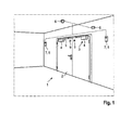
- Fig. 1 shows a locking assembly 1 according to the first embodiment. Shown is a door 2. At this door 2, a door operator 3, designed as a door closer, mounted. The door operator 3 comprises a housing 4 and a slide rail 5. In the housing 4, a closing spring is integrated. The force is transmitted from this closing spring via a linkage on the side mounted slide 5.
- the locking arrangement 1 comprises two signal transmitters 6. These are designed as smoke or fire detectors and mounted on the ceiling.
- Another component of the locking arrangement 1 is a locking device 7 and a triggering device 8.
- two locking devices 7 are provided for both wings of the door 2.
- On the wings of the door 2 are counterparts 9. These counterparts 9 cooperate with the electromagnets in the Feststefhrorraumen 7.
- the triggering device 8 is integrated here in the locking device 7. In this case, there is one integrated trigger device 8 per locking device 7.
- the dashed lines indicate radio links between the various components.
- the signal generator 6 via a radio link with the tripping devices 8.
- the signal generator 6 generate a first signal. This is transmitted by radio to the tripping devices 8.
- the triggering device 8 in turn are arranged together with the locking devices 7 in a housing and connected within this housing via cables.
- the tripping devices 8 generate a second signal. This second signal is forwarded to the locking devices 7. This releases the locking devices 7 and the door is released.
- the energy pre-stored in the closing springs can close the door leaves of the door 2.
- the illustrated housing for the locking devices 7 and tripping devices 8 each include a battery. These batteries are designed for the simultaneous power supply of the locking device 7 and the triggering device 8. Instead of a battery can further mains voltage independent power sources such as accumulators or solar cells are used.
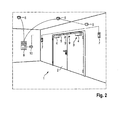
- Fig. 2 shows a second embodiment of the locking arrangement according to the invention 1.
- a single triggering device 8 is provided. This is not, as in the first embodiment, integrated into the locking devices 7, but is, designed as a fire alarm panel, spaced from the other components.
- the signal generator 6 transmit the first signal by means of a wired data line to the triggering device 8.
- the signal generator 6 can also transmit the first signal by means of radio to the triggering device 8.
- the triggering device 8 comprises a radio module 10.
- This radio module 10 generates the second signal.
- the second signal is transmitted via radio to the Feststetivorraumen 7.
- each of the illustrated signal generator 6 includes its own mains voltage independent power source, preferably a battery for power supply.
- each of the locking devices 7 includes its own mains voltage-independent power supply.
- the triggering device 8 may also have its own mains voltage-independent power supply, preferably a battery supply.
- the triggering device 8 is connected to the building electricity network.
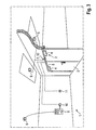
- Fig. 3 shows a third embodiment of the locking arrangement according to the invention 1.
- two tripping devices are provided.
- the triggering device 8 designed as a fire alarm panel, is shown here.
- a further triggering device 12 is shown integrated in the door actuator 3.
- the one signal transmitter 6 reports the first signal wired to the triggering device 8.
- Two other signalers 6 report via a direct radio link, the first signal to the other Tripping device 12, which is integrated in the door actuator 3.
- the integrated in the door operator 3 further trigger device 12 may have either a radio link or a wired data line to the locking device 7.
- the locking device 7 is integrated into the slide rail 5 of the door operator 3 and blocked here the slider.
- a radio hand switch 11 This radio hand switch 11 can be operated manually and generates the first signal.
- the radio handset 11 is connected via radio with the further triggering device 12.
- the locking device 7, the triggering device 8, the signal generator 6 and the mains voltage independent power source can be arranged individually or in different combinations in the slide or within a housing of the door operator.
- the locking device 7, the triggering device 8, the signal generator 6 and the mains voltage independent power source can be arranged in different combinations locally on the wall in the region of the door and / or on the door. It is also conceivable that the locking device 7, the triggering device 8, the signal generator 6 and the mains voltage-independent power source are arranged in different combinations in the region of the door at a mounting position.
- a slide rail system may be used, in which the slide rail system consists of a slide rail, in which a slider and the locking device are arranged, a smoke detector, a triggering device and a power source.
- the smoke detector and the triggering device are preferably each arranged on a circuit board.
- the boards are preferably at least partially in a housing, wherein a connector is inserted, which connects the housing with the slide rail. Further, another connector connects the slide rail to a connector on which an end cap is disposed. Another end cap cooperates with the system board with the connectors receiving plugs to receive the power source.
- a cover covers the slide rail system in operative connection with the end caps, with apertures and / or recesses for the smoke detector and the smoke detector board and the system board provided on the cover.
Landscapes
- Physics & Mathematics (AREA)
- Electromagnetism (AREA)
- Engineering & Computer Science (AREA)
- Mechanical Engineering (AREA)
- Lock And Its Accessories (AREA)
- Special Wing (AREA)
Applications Claiming Priority (1)
| Application Number | Priority Date | Filing Date | Title |
|---|---|---|---|
| DE102010061385A DE102010061385A1 (de) | 2010-12-21 | 2010-12-21 | Feststellanordnung für eine Tür |
Publications (2)
| Publication Number | Publication Date |
|---|---|
| EP2468992A2 true EP2468992A2 (fr) | 2012-06-27 |
| EP2468992A3 EP2468992A3 (fr) | 2016-01-20 |
Family
ID=45062787
Family Applications (1)
| Application Number | Title | Priority Date | Filing Date |
|---|---|---|---|
| EP11009171.7A Withdrawn EP2468992A3 (fr) | 2010-12-21 | 2011-11-18 | Agencement de réglage pour une porte |
Country Status (2)
| Country | Link |
|---|---|
| EP (1) | EP2468992A3 (fr) |
| DE (1) | DE102010061385A1 (fr) |
Cited By (5)
| Publication number | Priority date | Publication date | Assignee | Title |
|---|---|---|---|---|
| DE102013216106A1 (de) * | 2013-08-14 | 2015-02-19 | Gretsch-Unitas GmbH Baubeschläge | Feststellanlage |
| EP3029249A1 (fr) | 2014-12-01 | 2016-06-08 | Gretsch-Unitas GmbH Baubeschläge | Système de porte doté d'un cadre de porte, d'une porte et d'une installation de blocage |
| DE102014225297A1 (de) * | 2014-12-09 | 2016-06-09 | Geze Gmbh | Feststellanlage |
| EP3064690A1 (fr) * | 2015-03-02 | 2016-09-07 | DORMA Deutschland GmbH | Agencement pour une porte |
| WO2017020453A1 (fr) * | 2015-08-06 | 2017-02-09 | 苏州市富尔达科技股份有限公司 | Dispositif et système de fermeture automatique de porte coupe-feu |
Families Citing this family (3)
| Publication number | Priority date | Publication date | Assignee | Title |
|---|---|---|---|---|
| DE102015000611A1 (de) * | 2015-01-16 | 2016-07-21 | Assa Abloy Sicherheitstechnik Gmbh | Verriegelungsvorrichtung für eine Tür und/oder ein Fenster |
| DE102016210776A1 (de) * | 2016-06-16 | 2017-12-21 | Geze Gmbh | Feststellanlage |
| DE102021208025A1 (de) | 2021-07-26 | 2023-01-26 | Geze Gmbh | Brandschutz-Feststellanlage für eine Brandschutztür, Brandschutz-Türsystem und Verfahren zum Betreiben einer Brandschutz-Feststellanlage |
Family Cites Families (7)
| Publication number | Priority date | Publication date | Assignee | Title |
|---|---|---|---|---|
| US4440428A (en) * | 1981-09-01 | 1984-04-03 | Jessup Frank L | Apparatus for delaying the closing of a door |
| US6225768B1 (en) * | 1998-08-12 | 2001-05-01 | The Cookson Company | Automatic door safety system with multiple safety modes |
| DE102004039894A1 (de) * | 2003-11-25 | 2005-06-30 | Martin Reuter | Feststellvorrichtung zum Offenhalten einer selbstschliessenden Tür |
| DE102005013215B4 (de) * | 2005-03-20 | 2010-09-23 | Martin Reuter | Feststellvorrichtung |
| DE202006004069U1 (de) * | 2005-03-20 | 2006-06-22 | Reuter, Martin | Feststellvorrichtung |
| DE202007003739U1 (de) * | 2007-03-12 | 2007-08-23 | Waldhelm, Matthias | Zugelassener Türoffenhalter ohne Anschluss an den öffentlichen Energieversorger |
| US8231151B2 (en) * | 2009-05-07 | 2012-07-31 | Simplexgrinnell Lp | Magnetic releasing and securing device |
-
2010
- 2010-12-21 DE DE102010061385A patent/DE102010061385A1/de not_active Withdrawn
-
2011
- 2011-11-18 EP EP11009171.7A patent/EP2468992A3/fr not_active Withdrawn
Non-Patent Citations (1)
| Title |
|---|
| None |
Cited By (8)
| Publication number | Priority date | Publication date | Assignee | Title |
|---|---|---|---|---|
| DE102013216106A1 (de) * | 2013-08-14 | 2015-02-19 | Gretsch-Unitas GmbH Baubeschläge | Feststellanlage |
| EP2851500A1 (fr) * | 2013-08-14 | 2015-03-25 | Gretsch-Unitas GmbH Baubeschläge | Installation de blocage |
| EP3029249A1 (fr) | 2014-12-01 | 2016-06-08 | Gretsch-Unitas GmbH Baubeschläge | Système de porte doté d'un cadre de porte, d'une porte et d'une installation de blocage |
| DE102014225297A1 (de) * | 2014-12-09 | 2016-06-09 | Geze Gmbh | Feststellanlage |
| DE102014225297B4 (de) * | 2014-12-09 | 2017-11-09 | Geze Gmbh | Feststellanlage |
| EP3064690A1 (fr) * | 2015-03-02 | 2016-09-07 | DORMA Deutschland GmbH | Agencement pour une porte |
| WO2017020453A1 (fr) * | 2015-08-06 | 2017-02-09 | 苏州市富尔达科技股份有限公司 | Dispositif et système de fermeture automatique de porte coupe-feu |
| US11078712B2 (en) | 2015-08-06 | 2021-08-03 | Suzhou Fuerda Technology Co., Ltd. | Automatic fire door closing device and system |
Also Published As
| Publication number | Publication date |
|---|---|
| EP2468992A3 (fr) | 2016-01-20 |
| DE102010061385A1 (de) | 2012-06-21 |
Similar Documents
| Publication | Publication Date | Title |
|---|---|---|
| EP2468992A2 (fr) | Agencement de réglage pour une porte | |
| EP1850445B1 (fr) | Point de chargement de batterie et procédé de fonctionnement et de fabrication correspondant | |
| EP2236732B1 (fr) | Porte | |
| EP3460155A1 (fr) | Dispositif d'actionnement au moins partiellement automatique d'un vantail de porte | |
| DE102017115702A1 (de) | Gehäuse für eine Stromtankstelle und Verfahren zu dessen Herstellung | |
| WO2010097347A1 (fr) | Système de sécurité comportant un dispositif de contrôle | |
| WO2017005388A1 (fr) | Système de maintenance et de surveillance pour la surveillance d'un élément formant porte | |
| DE102007041383B4 (de) | Rauch- und Wärmeabzugs- und Lüftungseinrichtung umfassend Rauch- und Wärmeabzugs- und Lüftungsgeräte mit jeweils einem motorischen Antrieb | |
| EP2946649B1 (fr) | Sécurité d'une position de fermeture d'un organe de fermeture d'une enceinte | |
| DE19929193A1 (de) | Flucht- und Rettungswegeinrichtung für mindestens eine Tür oder ein Fenster in Flucht- und Rettungswegen | |
| DE102021201827B3 (de) | Türantrieb sowie Verfahren zur Bestimmung eines Flügelwinkels eines Türflügels | |
| DE102006042469A1 (de) | Schließanlage und Tür mit Schließanlage | |
| DE102017130301A1 (de) | Betätigungseinrichtung | |
| WO2021074293A1 (fr) | Système de sécurité de porte, procédé de fonctionnement d'un système de sécurité de porte et moyen de transport | |
| EP0908594A2 (fr) | Dispositif de surveillance d'une zone d'ouverture d'une porte | |
| DE10223516A1 (de) | Sicherheits-Schaltungsanordnung für ein Ablufsystem | |
| EP1932994A1 (fr) | Entraînement pour un panneau de porte ou de fenêtre | |
| DE102018120252A1 (de) | Kommunikationsvorrichtung | |
| DE202018102478U1 (de) | Gebäude- oder Einfriedungsabschlussantriebsperipheriegerät und -system | |
| DE102013109927A1 (de) | Torflügel mit Schlupftür sowie damit versehenes Tor | |
| EP3670794A1 (fr) | Agencement de porte et procédé de fonctionnement d'un agencement de porte | |
| WO2018130533A1 (fr) | Système d'entraînement de porte et procédé de fonctionnement associé | |
| DE202011000356U1 (de) | Solarantrieb für ein bewegliches Gebäudeteil | |
| DE102017204744B4 (de) | Vorrichtung zur Überwachung eines Gebäudes | |
| EP3349187B1 (fr) | Procédé permettant d'obtenir au moins un paramètre de commande d'au moins un système de porte |
Legal Events
| Date | Code | Title | Description |
|---|---|---|---|
| AK | Designated contracting states |
Kind code of ref document: A2 Designated state(s): AL AT BE BG CH CY CZ DE DK EE ES FI FR GB GR HR HU IE IS IT LI LT LU LV MC MK MT NL NO PL PT RO RS SE SI SK SM TR |
|
| AX | Request for extension of the european patent |
Extension state: BA ME |
|
| PUAI | Public reference made under article 153(3) epc to a published international application that has entered the european phase |
Free format text: ORIGINAL CODE: 0009012 |
|
| RAP1 | Party data changed (applicant data changed or rights of an application transferred) |
Owner name: DORMA DEUTSCHLAND GMBH |
|
| PUAL | Search report despatched |
Free format text: ORIGINAL CODE: 0009013 |
|
| AK | Designated contracting states |
Kind code of ref document: A3 Designated state(s): AL AT BE BG CH CY CZ DE DK EE ES FI FR GB GR HR HU IE IS IT LI LT LU LV MC MK MT NL NO PL PT RO RS SE SI SK SM TR |
|
| AX | Request for extension of the european patent |
Extension state: BA ME |
|
| RIC1 | Information provided on ipc code assigned before grant |
Ipc: E05C 19/16 20060101ALI20151216BHEP Ipc: E05C 17/56 20060101AFI20151216BHEP |
|
| 17P | Request for examination filed |
Effective date: 20160203 |
|
| RBV | Designated contracting states (corrected) |
Designated state(s): AL AT BE BG CH CY CZ DE DK EE ES FI FR GB GR HR HU IE IS IT LI LT LU LV MC MK MT NL NO PL PT RO RS SE SI SK SM TR |
|
| RAP1 | Party data changed (applicant data changed or rights of an application transferred) |
Owner name: DORMAKABA DEUTSCHLAND GMBH |
|
| STAA | Information on the status of an ep patent application or granted ep patent |
Free format text: STATUS: EXAMINATION IS IN PROGRESS |
|
| 17Q | First examination report despatched |
Effective date: 20180611 |
|
| STAA | Information on the status of an ep patent application or granted ep patent |
Free format text: STATUS: THE APPLICATION IS DEEMED TO BE WITHDRAWN |
|
| 18D | Application deemed to be withdrawn |
Effective date: 20181023 |