EP2412488B1 - Power Tool - Google Patents
Power Tool Download PDFInfo
- Publication number
- EP2412488B1 EP2412488B1 EP11186988.9A EP11186988A EP2412488B1 EP 2412488 B1 EP2412488 B1 EP 2412488B1 EP 11186988 A EP11186988 A EP 11186988A EP 2412488 B1 EP2412488 B1 EP 2412488B1
- Authority
- EP
- European Patent Office
- Prior art keywords
- light
- power tool
- pivot shaft
- emitting element
- lever
- Prior art date
- Legal status (The legal status is an assumption and is not a legal conclusion. Google has not performed a legal analysis and makes no representation as to the accuracy of the status listed.)
- Expired - Lifetime
Links
Images


Classifications
-
- B—PERFORMING OPERATIONS; TRANSPORTING
- B25—HAND TOOLS; PORTABLE POWER-DRIVEN TOOLS; MANIPULATORS
- B25B—TOOLS OR BENCH DEVICES NOT OTHERWISE PROVIDED FOR, FOR FASTENING, CONNECTING, DISENGAGING OR HOLDING
- B25B23/00—Details of, or accessories for, spanners, wrenches, screwdrivers
- B25B23/18—Devices for illuminating the head of the screw or the nut
-
- B—PERFORMING OPERATIONS; TRANSPORTING
- B25—HAND TOOLS; PORTABLE POWER-DRIVEN TOOLS; MANIPULATORS
- B25F—COMBINATION OR MULTI-PURPOSE TOOLS NOT OTHERWISE PROVIDED FOR; DETAILS OR COMPONENTS OF PORTABLE POWER-DRIVEN TOOLS NOT PARTICULARLY RELATED TO THE OPERATIONS PERFORMED AND NOT OTHERWISE PROVIDED FOR
- B25F5/00—Details or components of portable power-driven tools not particularly related to the operations performed and not otherwise provided for
- B25F5/02—Construction of casings, bodies or handles
- B25F5/021—Construction of casings, bodies or handles with guiding devices
-
- Y—GENERAL TAGGING OF NEW TECHNOLOGICAL DEVELOPMENTS; GENERAL TAGGING OF CROSS-SECTIONAL TECHNOLOGIES SPANNING OVER SEVERAL SECTIONS OF THE IPC; TECHNICAL SUBJECTS COVERED BY FORMER USPC CROSS-REFERENCE ART COLLECTIONS [XRACs] AND DIGESTS
- Y10—TECHNICAL SUBJECTS COVERED BY FORMER USPC
- Y10T—TECHNICAL SUBJECTS COVERED BY FORMER US CLASSIFICATION
- Y10T408/00—Cutting by use of rotating axially moving tool
- Y10T408/21—Cutting by use of rotating axially moving tool with signal, indicator, illuminator or optical means
-
- Y—GENERAL TAGGING OF NEW TECHNOLOGICAL DEVELOPMENTS; GENERAL TAGGING OF CROSS-SECTIONAL TECHNOLOGIES SPANNING OVER SEVERAL SECTIONS OF THE IPC; TECHNICAL SUBJECTS COVERED BY FORMER USPC CROSS-REFERENCE ART COLLECTIONS [XRACs] AND DIGESTS
- Y10—TECHNICAL SUBJECTS COVERED BY FORMER USPC
- Y10T—TECHNICAL SUBJECTS COVERED BY FORMER US CLASSIFICATION
- Y10T408/00—Cutting by use of rotating axially moving tool
- Y10T408/96—Miscellaneous
Definitions
- the present invention relates to a power tool that has a light emitting element.
- DE 297 19 020 U discloses a power tool comprising: a motor as a drive power source, a body housing the motor and having an end output unit for chucking an end tool driving a fastener; a handle grip provided integrally with the body; a light unit having a light-emitting element for illuminating a fastener located at a distal end of the end tool, the end tool being driven by the motor to tighten the fastener to a work-piece; wherein a pull trigger is disposed at a top part of the handle grip for starting/stopping driving the end tool and to turn on the light emitting element.
- Power tool's used to drive a screw or other threaded fastener by way of a bit or other end tool, and having a light, are now common.
- the light illuminates both the fastener being affixed to the workpiece, and the bit used to drive the fastener, thereby making it easier to use the power tool in dark places.
- this power tool 401 has a body 410, and inside the body 410 has a motor not shown as the drive source, and mechanical parts not shown for transferring torque from the motor not shown.
- An end output unit not shown is housed near the distal end inside the body 410, and a tool chuck 411 is disposed to this distal end.
- the tool chuck 411 is drivably linked to the end output unit not shown, and an end tool is chucked in the tool chuck 411.
- the end output unit not shown is drivably linked inside the body 410 to the motor not shown through the mechanical parts not shown, torque from the motor is thereby transferred to the end output unit, and the end output unit is thus driven.
- a handle grip 410C that is gripped by the user when using the power tool is rendered integrally to the body 410.
- a pull trigger 413 for starting and stopping driving the motor not shown is disposed at the top part of the handle grip 410C.
- a light unit 420 is externally affixed to a position on top of the body 410.
- the light unit 420 has a light-emitting element not shown, and can thereby illuminate a fastener not shown that is driven by the end tool not shown.
- a battery pack 412 is also disposed at the bottom part of the handle grip 410C. This battery pack 412 houses a battery not shown that is the power source for supplying power, and the battery not shown is electrically connected to the motor not shown.
- the lighting angle of the light unit is fixed.
- the tools chucked into the end of such power tools vary in length from 60 mm to 150 mm.
- a problem here is that because the lighting angle is fixed with such conventional power tools, light cannot always thrown onto the fitting between the bit and the head of the screw used as the fastener, or on the tip of the screw, when the bit is changed, and it becomes difficult to see.
- the light unit is fixed directly to the body, vibration produced when using the power tool can result in continuity failures in the light-emitting element or wiring failures.
- Japanese laid open Patent Application Publication No. 2001-300867 discloses a power tool in which the light unit has a flexible shaft extending from the bottom of the handle grip. A light-emitting element is disposed at the distal end of this flexible shaft. Because the flexible shaft can be bent to any desired direction, the lighting angle of the light-emitting element can be freely adjusted.
- a problem with the conventional power tool described in the Japanese Patent Application Publication No. 2001-300867 is that vibration produced from using the power tool causes the light from the light-emitting element to waver because the lighting angle of the light-emitting element is held by the flexible shaft, and it is difficult to see the target.
- power tools described in Japanese Utility Model application Kokai Nos. H3-79279 , H1-117882 and S55-151409 have a switch for turning illumination from the light-emitting element on and off. If, for example, the user forgets to turn the switch off, the battery is consumed even though the light is not being used, and the light then may not turn on when it is actually needed.
- the light-emitting element projects light from only one direction.
- the light casts a shadow of the end tool onto the workpiece when the bit is fit into the screw head, making it difficult to see.
- white incandescent lights are generally used for the light-emitting element in the prior art, but contrast is low and a relatively high wattage incandescent light must be used to achieve sufficient brightness. The power supply must therefore become bulky, and this degrades operability.
- an object of the present invention is to provide a power tool having a light unit that does not get in the way.
- a further object of the invention is to provide a power tool that prevents depletion of the power supply due to the light switch of the light unit not being turned off.
- a yet further object of the invention is to provide a power tool that is resistant to continuity failures in the light-emitting element and interruptions in wiring members.
- a yet further object of the invention is to provide a small, economical power tool.
- a yet further object of the invention is to provide a power tool providing high contrast illumination and capable of minimizing generation of a shadow of the end tool.
- a power tool according to the present invention is defined in claim 1.
- a power tool 1 not according to the present invention will be described below with reference to Fig. 1 to Fig. 7 .
- this power tool 1 is specifically described as an impact driver having a generally T-shaped body 10.
- This body 10 includes a hammer case 10A forming the front end part of the body 10, and a housing 10B connected to the hammer case 10A and forming the back part of the body 10.
- a motor not shown functioning as the drive source, and mechanical parts not shown composed of, for example, a speed reduction mechanism for transferring motor torque, are housed inside the housing 10B.
- the speed reduction mechanism includes a planetary gear unit not shown and other parts.
- An end output unit not shown is housed inside the hammer case 10A, and a chuck 11 for holding a tool or bit is disposed to the hammer case 10A.
- the chuck 11 has a hollow, substantially cylindrical insertion end for inserting therein a shaft-like end tool such as a bit 2, 3 (see Fig. 6 and Fig. 7 ).
- One of the tool bit 2, 3 is detachably inserted into the chuck 11.
- the end output unit not shown has an impact mechanism not shown for converting the rotary force of the motor not shown to an impact force and driving the bit 2, 3, and is drivingly linked to the motor not shown.
- the screw or other fastener 4, 5 ( Fig. 6 , Fig. 7 ) is tightened to the workpiece 6 or loosened therefrom.
- a handle grip 10C extends from a lower portion of the body 10.
- the handle grip 10C is integrally with the body 10, and a battery pack 12 internally housing a battery not shown is disposed to the bottom of the handle grip 10C.
- a pull trigger 13 for starting and stopping the motor is disposed to the top part of the handle grip 10C.
- Contacts not shown and connection terminals not shown for electrically connecting the motor not shown inside the housing 10B to the battery not shown inside the battery pack 12 are also disposed inside the handle grip 10C.
- the battery pack 12 is detachably attached to the handle grip 10C, and the internal battery not shown supplies power to the motor not shown.
- a light unit 20 is disposed to a position at the bottom of the handle grip 10C and immediately above the battery pack 12.
- the light unit 20 includes a lever 21 and a pivot shaft 30 and a pivot shaft support part 40.
- the lever 21 is provided integrally with one end 30A of the pivot shaft 30 having substantially cylindrical shape.
- the pivot shaft support part 40 is provided at a lower portion of the handle grip 10C for supporting the pivot shaft 30. More specifically, the pivot shaft 30 is supported by the support part 40 rotably about its axis and axially movable along its axis.
- the lever 21 has a base end connected to the pivot shaft 30 and has a free end.
- the base end of the lever 21 is connected to the pivot shaft 30 so as to cover an opening in the one end 30A of the substantially cylindrical pivot shaft 30.
- the lever 21 can therefore pivotally moved in conjunction with the pivot shaft 30 about the axis of the pivot shaft 30, and can move along the axis of the pivot shaft 30.
- the pivot shaft 30 has another end 30B which is an open end.
- the pivot shaft support part 40 is composed of a first pivot shaft support part 41 and a second pivot shaft support part 42 shaped symmetrically sideways the body 10.
- a through-hole 40a passes through these parts 41 and 42.
- the axis of this through-hole 40a is also oriented sideways to the body 10, that is, in the right-to-left direction as seen in Fig. 4 .
- the pivot shaft support part 40 is provided integrally with the handle grip 10C, and the pivot shaft 30 is disposed rotatably about its axis to the handle grip 10C and movable in the axial direction while the pivot shaft 30 is extending through the through-hole 40a.
- the pivot shaft 30 passes from the left to the right side of the body 10 when viewed from the back side of the power tool 1, that is, from the left to the right side in Fig. 4 , such that the one end 30A of the pivot shaft 30 connected to the lever 21 is positioned on the left side and the other end 30B is positioned on the right side of the body 10 when seen from the back of the power tool 1.
- a hand strap 43 (see Fig. 2 ) is disposed at a connecting position of the pivot shaft support part 40 to the handle grip 10C.
- First engaging teeth 41A and second engaging teeth 42A are formed in the part of and at the through-hole 40a of the first pivot shaft support part 41 and second pivot shaft support part 42.
- First engaging teeth 41A and second engaging teeth 42A are disposed at symmetrical positions sideways to the body 10 substantially in the middle in the axial direction of the through-hole 40a.
- First engaging teeth 41A and second engaging teeth 42A protrude radially inwardly of the through-hole 40a.
- a reduced inner diameter part is provided in the through-hole 40a at positions corresponding to the locations of the first engaging teeth 41A and second engaging teeth 42A.
- first engaging teeth 41A and second engaging teeth 42A in the axial direction of the through-hole 40a respectively form first resilient member contact part 41B and second resilient member contact part 42B, respectively.
- the distance between first resilient member contact part 41B and second resilient member contact part 42B is approximately 10 mm.
- fitting teeth 31 are provided to the pivot shaft 30 at a position opposite to the first engaging teeth 41A.
- the fitting teeth 31 are provided in a circumferential direction of the pivot shaft 30 at a position offset towards the one end 30A from the approximate middle in the axial direction of the pivot shaft 30 so that the fitting teeth 31 is meshedly engagable with the first engaging teeth 41A when positioned as shown in Fig. 1 to Fig. 7 , that is, when the power tool 1 is used with the one end 30A of pivot shaft 30 positioned to the left side of the handle grip 10C as shown in Fig. 4 .
- a nut 32 ( Fig. 4 ) is located on the inside surface of the substantially tubular pivot shaft 30 at a position near the one end 30A.
- An inner diameter of the nut 32 is equal to an inner diameter of a major part of the pivot shaft 30 where the nut 32 is not disposed.
- a single bolt 33 is inserted along the inner peripheral surface of the nut 32 and the inner peripheral surface of the major part of the pivot shaft 30. The bolt 33 is fixed to the pivot shaft 30 by threadingly engaging the bolt 33 with the nut 32. The bolt 33 is detachable from the pivot shaft 30.
- a coin slot 33a into which a coin can be fit is formed in a head 33A of the bolt 33.
- the bolt 33 can be screwed into the nut 32 of the pivot shaft 30, or the bolt 33 can be unscrewed from and removed from the pivot shaft 30 by inserting a coin to the coin slot 33a and turning the bolt 33.
- the bolt 33 is inserted from the open end at the other end of the pivot shaft 30, and is screwed into the nut 32, and fastened to the pivot shaft 30 before the power tool 1 is used.
- a resilient member 34 such as a spring is disposed inside the through-hole 40a between the head 33A of bolt 33 and second engaging teeth 42A.
- One end of the resilient member 34 is in abutment with the second resilient member contact part 42B of the second engaging teeth 42A, and the other end of the resilient member 34 is in abutment with the head 33A of bolt 33.
- the resilient member 34 is a compression spring compressed between the head 33A of bolt 33 and the second resilient member contact part 42B. The resilient member 34 therefore urges the head 33A of bolt 33 integrally with the pivot shaft 30 to the right as seen in Fig. 4 , that is, in the direction for allowing the fitting teeth 31 to.be engaged with the first engaging teeth 41A.
- the pivot shaft 30 When the lever 21 is moved resisting the urging force of the resilient member 34 in the direction away from the handle grip 10C, that is, is moved to the left in Fig. 4 , in order to disengage the fitting teeth 31 from the first engaging teeth 41A, the pivot shaft 30 also moves in the same direction. As the lever 21 is moved further in this direction, the resilient member 34 becomes completely compressed and cannot be further compressed. Because the head 33A of the bolt 33 contacts the other end of the resilient member 34, the bolt 33 and pivot shaft 30 which moves in unison with the bolt 33, reach a point where they cannot move further to the left in Fig. 4 . Therefore, the pivot shaft 30 is prevented from dropping out of the through-hole 40a.
- the bolt 33 thus functions as a retainer preventing separation of the pivot shaft 30 from the through-hole 40a.
- the pivot shaft support part 40 is composed of first pivot shaft support part 41 and second pivot shaft support part 42 symmetrical therewith in the lateral direction of the body 10, and first engaging teeth 41A and second engaging teeth 42A are disposed at symmetrical positions sideways to the body 10, the lever 21 can be fit into the handle grip 10C from the left side as shown in Fig. 4 , or from the right side of the handle grip 10C rather than the left side as may be needed.
- the bolt 33 can be removed from pivot shaft 30, and the pivot shaft 30 is then removed from through-hole 40a.
- the pivot shaft 30 is then inserted from the right side in Fig. 4 to the through-hole 40a, the resilient member 34 is fit to the end of the pivot shaft 30, and the one end of the resilient member 34 is set against the first resilient member contact part 41B of first engaging teeth 41A.
- the bolt 33 is then screwed into the nut 32 of pivot shaft 30 and fixed to the pivot shaft 30 so that the other end of resilient member 34 contacts the head 33A.
- the lever 21 is thereby installed at the right side of the handle grip 10C as seen in Fig. 4 .
- the lever 21 can be installed at a position for avoiding interference with operation of the power tool 1 regardless of whether the user is right-handed or left-handed.
- first engaging teeth 41A of first pivot shaft support part 41 when the first engaging teeth 41A of first pivot shaft support part 41 is in meshing engagement with the fitting teeth 31, the other end of second engaging teeth 42A functions as the resilient member contact part. Furthermore, when the second engaging teeth 42A of second pivot shaft support part 42 is in meshing engagement with the fitting teeth 31, the end of first engaging teeth 41A functions as the resilient member contact part.
- first pivot shaft support part 41 second pivot shaft support part 42, first engaging teeth 41A, second engaging teeth 42A, resilient member 34, first resilient member contact part 41B, second resilient member contact part 42B, and bolt 33 functions as lighting angle adjusting and holding means.
- a recessed channel 21a is formed encircling the pivot shaft 30 at the base end of the lever 21, which is connected to the pivot shaft 30 and is opposed to the first pivot shaft support part 41.
- An annular washer 22 made of rubber approximately 2 mm thick is fit into this channel 21a. The washer 22 therefore encircles the pivot shaft 30 at a position on the end of the lever 21 connected to the pivot shaft 30. This washer 22 functions as a vibration damper.
- the open end of the through-hole 40a in the first pivot shaft support part 41 is configured to contact the washer 22 when no force is applied to the lever 21 and the lever 21 has moved to the right-most side in Fig. 4 due to the urging force of the resilient member 34. Harsh vibration transmitted to the handle grip 10C when the power tool 1 is used is therefore absorbed by this washer 22. Thus, the washer 22 efficiently prevents the vibration from being transmitted to the lever 21. As a result, interruptions in wiring members and conductivity failure in the light-emitting element 23 of a lighting circuit 27 disposed inside the lever 21 as described below can be prevented.
- the lever 21 has a thick base end connected to the pivot shaft 30.
- the lever 21 becomes gradually smaller towards the free end thereof, and has a constant thickness from a predetermined position. Therefore, the elongated portion of the lever 21 is spaced away from the handle grip 10C with a gap L of approximately 20 mm as shown in Fig. 4 .
- Fig. 4 shows the rear view of the power tool 1, and the elongated portion of the lever 21 therefore extends in the direction perpendicular to the drawing sheet.
- the lever 21 houses therein a light-emitting element 23, which is composed of an LED emitting yellow light, a lens 24 made of transparent plastic plate, and a power source 25 composed of an N size battery.
- the light-emitting element 23 is disposed in the free end of the lever 21 for emitting light in the direction from the base end to the free end of the lever 21.
- the lens 24 covers the light-emitting element 23 and protects the light-emitting element 23.
- the power source 25 is housed inside the base end of the lever 21 connected to the pivot shaft 30, and is electrically connected to the light-emitting element 23.
- a push-button ON switch 26A for turning light emission from the light-emitting element 23 on, and a push-button OFF switch 26B for turning the light-emitting element 23 off, are disposed on the outside surface 21A of the lever 21.
- ON switch 26A, OFF switch 26B, and light-emitting element 23 are mounted on a circuit board 26, rendering a switching means.
- a semiconductor timer circuit 26C is also mounted on the circuit board 26.
- the semiconductor timer circuit 26C is adapted for automatically turning the light-emitting element 23 off 30 seconds after the light-emitting element 23 is turned on by means of the ON switch 26A.
- the power source 25, light-emitting element 23, ON switch 26A, OFF switch 26B, and timer circuit 26C are connected to each other and form a lighting circuit 27 as shown in Fig. 5 .
- the lighting circuit 27 also has transistors Tr1, Tr2, and a plurality of resistors. Because the circuit board 26 and timer circuit 26C are relatively thin, they are disposed inside the lever 21 at a position near the free end, and the relatively thick power source 25 is disposed inside the base part of the lever 21.
- the timer circuit 26C functions as an off circuit.
- the ON switch 26A and OFF switch 26B are both push-button switches composed of momentary switches, and when the user presses and then releases the switch, the contacts open.
- timer circuit 26C sets output Vt to L level soon after current supply starts, the timer circuit 26C continues to hold Tr1 and Tr2 on even after the user releases ON switch 26A, and thus self-holds current supply to the light-emitting element 23 and timer circuit 26C.
- contrast can be improved and the illuminated bit 2, 3 and fasteners 4, 5 can be seen clearly. Furthermore, because contrast is high, it is not necessary to increase electrical consumption, and the size of the power source 25 and lighting circuit 27 can be reduced. Furthermore, because current consumption is 1/10 or less as large as a normal incandescent flashlight bulb, a small battery, such as a standard N size battery, can be used, and the power tool 1 can be made small and economical.
- the light-emitting element 23 is provided at the free end of the lever 21 that can be held stationary at a desired angle, so that the emission angle of the light-emitting element 23 can be freely adjusted, lighting can be optimized for the bit 2, 3 and fasteners 4, 5, and the fasteners 4, 5 can be comfortably fastened.
- the light-emitting element 23 is disposed in the free end of the lever 21, and the pivot position of the lever 21 is held by engagement of the fitting teeth 31 of pivot shaft 30 connected integrally to lever 21 with the first engaging teeth 41A or second engaging teeth 42A disposed in the handle grip 10C, vibration in the body 10 when using the power tool 1 will not cause the emitted light to vibrate thereby facilitating observation to the target.
- the lever 21 is returned to the original resting position shown in Fig. 1 .
- the lever 21 cannot interfere with gripping the handle, and the power tool 1 can be used easily.
- the lever 21 in the initial pivot position shown in Fig. 1 is pulled away from the bottom of the handle grip 10C (that is, in the direction lifting off of the page in Fig. 6 ) approximately 5 mm and turned to a pivot angle ⁇ of approximately 40°, and the lever 21 is then released.
- the lever 21 is thus fixed in the position shown in Fig. 6 and cannot be pivotally moved any more.
- the ON switch 26A is then pressed so that the light-emitting element 23 starts emitting in the direction of the fastener 4, and the trigger 13 is pulled to drive the bit 2 and tighten the fastener 4.
- the lever 21 in the initial rotary position shown in Fig. 1 is pulled away from the bottom of the handle grip 10C (that is, in the direction lifting off of the page in Fig. 7 ) approximately 5 mm and turned to the pivot angle ⁇ of approximately 20°, and the lever 21 is then released.
- the lever 21 is thus fixed in the position shown in Fig. 7 and cannot be pivoted any more.
- the ON switch 26A is then pressed so that the light-emitting element 23 starts emitting in the direction of the fastener 5, and the trigger 13 is pulled to drive the bit 3 and tighten the fastener 5.
- a coin not shown is first fit into the coin slot 33a to rotate the bolt 33 about its axis relative to the pivot shaft 30 and remove the bolt 33 from the pivot shaft 30.
- the pivot shaft 30 is removed from the through-hole 40a and then reinserted to the through-hole 40a from the right side.
- the resilient member 34 is fit to the end of the pivot shaft 30, and one end of the resilient member 34 is seated against the first resilient member contact part 41B of first engaging teeth 41A.
- the coin not shown is fit into the coin slot 33a to rotate the bolt 33 about its axis into the pivot shaft 30 while threadingly engaging the bolt 33 with the nut 32, thereby fixing the bolt 33 in the pivot shaft 30.
- the lever 21 is reinstalled to the handle grip 10C from the right side in Fig. 4 .
- the lever 21 is removably installed to the handle grip 10C, the lever 21 can be removed from the handle grip 10C and used as a handheld flashlight. Furthermore, because the lever 21 is thick at the base end connected to the pivot shaft 30 and becomes gradually thinner towards the free end, so that the elongated portion of the lever 21 is spaced away from the handle grip 10C with an appropriate gap L therebetween ( Fig. 4 ). Thus, the lever 21 can also function as a hook for hanging on the worker's belt or ladder, and an installation space to rest the power tool 1 when working in high places can be eliminated. Furthermore, because this hook and light unit 20 are rendered as one piece, they are convenient and do not get in the way.
- circuit board 26 and timer circuit 26C are disposed near the free end of the lever 21 and the power source 25 is disposed inside the base end of the lever 21, the part near the free end of the lever 21 imparted with the functionality of a hook can be rendered thin and small.
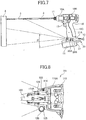
- the power tool 101 is different from the power tool 1 in that a light unit 120 is not provided at the bottom part of a handle grip 110C, but is positioned on an outside of a hammer case 110A at a distal end section 114A of an end output part 114.
- the end output part 114 forms a part of the body 110,and houses therein an impact mechanism not shown for converting torque from a motor not shown to an impact force and driving a bit 103.
- the end output part 114 has the distal end section 114A provided with the light unit 120.
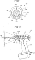
- the light unit 120 is almost ring-shaped following the circumference of the distal end section 114A of the substantially cylindrical end output part 114, and encircles the distal end section 114A.
- the light unit 120 has a flat ring like substrate 126 ( Fig. 9 ) substantially identical in shape to a body of the light unit 120 and disposed coaxially with the body of the light unit 120.
- the light unit 120 also has three light-emitting elements 123 ( Fig. 9 ), an ON switch 126A and OFF switch 126B, a timer circuit not shown, and a power source 125, each of which is rendered on the flat ring like substrate 126.
- the light-emitting elements 123 are disposed at equal intervals around the distal end section 114A so that they are mutually offset 120° around the axis of the bit 103, and oriented to emit light to the front of the power tool 101.
- the power source 125, ON switch 126A, and OFF switch 126B are also disposed on the same circle as the light-emitting elements 123. These are all covered by a transparent plastic lens 124. Further, as described previously, when using the power tool 101, the user presses ON switch 126A to turn the light-emitting elements 123 on and illuminate the fastener, and the light-emitting elements 123 turns off automatically approximately three minutes after the light turns on.
- a power tool 201 according to the present invention is described next with reference to Figs. 11 and 12 .
- the power tool 201 differs from the power tool 1 of Figs. 1 to 7 in that a light unit 220 is disposed at a position directly above a trigger 213 rather than at the bottom of a handle grip 210C.
- the power tool 201 also differs from the power tool 1 of Figs. 1 to 7 in that the light unit 220 is provided with a light-emitting element 223, ON switch 226A, and OFF switch 226B, but is not provided with a power source for exclusively driving the light-emitting element 223, a timer circuit, nor a lighting circuit.
- the light unit 220 is disposed immediately above the trigger 213, and has one light-emitting element 223 oriented to the front of a body 210.
- An ON switch 226A and OFF switch not shown are located close behind the light-emitting element 223.
- the front of the light-emitting element 223 is covered by a transparent lens 224.
- the light-emitting element 223, ON switch 226A, and OFF switch are connected to a circuit board 226 by a cord 228.
- the circuit board 226 is located inside the handle grip 210C and in confrontation with the back of the handle grip 210C, and a lighting circuit not shown including a timer circuit not shown is mounted on the circuit board 226.
- a power supply for exclusively driving the light-emitting element 223 is not disposed to the circuit board.
- the circuit board 226 is electrically connected to the battery 12A ( Fig. 11 ), and the light-emitting element 223 is powered by current from the battery 12A.
- the bit 103 When using the power tool 201, the bit 103 is driven and the light-emitting element 223 turns on when the user pulls the trigger 213, so that the fastener 104 is illuminated.
- the finger When the user extends the index finger toward the front of the bit 103 from the position gripping the handle grip 210C, the finger will not touch the light unit 220 because the light unit 220 is located directly above the trigger 213. The light unit 220 thus does not interfere with operation of the trigger 213, and operability to the power tool 201 can be improved.
- the light unit 220 does not project outside from the body 210 br battery pack 12, and the light unit 220 does not contact the neighboring or opposing member or get in the way even when using the power tool 201 in a confined location.
- the power tool 201 can be has a simple construction and produced at low cost. Yet further, wiring inside the body 210 can be simplified and a layout can be made compact.
- the power tool 301 differs from the power tool 1 shown in Figs. 1 to 7 in that an extensible member 321B and rotary joint 321C are disposed as parts of a lever 321. Note that for descriptive purposes, a stretched state of the extensible member 321B is shown by a solid line in Fig. 13 , and a shrinking state thereof is shown by a dotted line in Fig. 13 .
- the extensible member 321B is disposed in approximately the middle of the lever 321 between the base part and free end part thereof.
- An extension/retraction switch 329 is also disposed toward the base of the lever 321 from the extensible member 321B.
- the extensible member 321B is configured to extend and retract according to the operation of the extension/retraction switch 329.
- the rotary joint 321C is disposed on the free end side of the lever 321 at one end of the extensible member 321B.
- a configuration such as the lighting angle adjusting and holding means of the first embodiment is used as the rotary joint 321C, enabling the free end to be pivotally movable and be held at a specific angle relative to the extensible member 321B.
- An ON switch 326A and OFF switch not shown are located on the free end part of the lever 321.
- the light-emitting element not shown of the light unit 320 can be positioned more closely to the illuminated object and can emit light from the best angle, thereby making it easier to see the illuminated object.
- a spray nozzle for applying a coating can be disposed in place of the light-emitting element.
- a spray button is disposed instead of ON switch 326A.
- the object to be coated such as a bolt 304, can therefore be accurately and easily sprayed by turning the spray button on after positioning the spray nozzle close to the object to be coated.
- a power tool according to the present invention shall not be limited to the embodiment described above, and can be modified and improved in various ways.
- the motor of the power tools above-described is driven by electrical power, but a pneumatic motor can be used instead of the electric motor.
- the present invention can be widely used for tightening and loosening fasteners such as screws and bolts in the building site.
Landscapes
- Engineering & Computer Science (AREA)
- Mechanical Engineering (AREA)
- Details Of Spanners, Wrenches, And Screw Drivers And Accessories (AREA)
- Portable Power Tools In General (AREA)
Applications Claiming Priority (2)
| Application Number | Priority Date | Filing Date | Title |
|---|---|---|---|
| JP2002012182A JP2003211374A (ja) | 2002-01-21 | 2002-01-21 | 電動工具 |
| EP03701110A EP1477282B1 (en) | 2002-01-21 | 2003-01-17 | Power tool |
Related Parent Applications (3)
| Application Number | Title | Priority Date | Filing Date |
|---|---|---|---|
| EP03701110.3 Division | 2003-01-17 | ||
| EP03701110A Division EP1477282B1 (en) | 2002-01-21 | 2003-01-17 | Power tool |
| EP03701110A Division-Into EP1477282B1 (en) | 2002-01-21 | 2003-01-17 | Power tool |
Publications (2)
| Publication Number | Publication Date |
|---|---|
| EP2412488A1 EP2412488A1 (en) | 2012-02-01 |
| EP2412488B1 true EP2412488B1 (en) | 2017-03-15 |
Family
ID=27606035
Family Applications (3)
| Application Number | Title | Priority Date | Filing Date |
|---|---|---|---|
| EP12175676A Ceased EP2511049A1 (en) | 2002-01-21 | 2003-01-17 | Power tool |
| EP11186988.9A Expired - Lifetime EP2412488B1 (en) | 2002-01-21 | 2003-01-17 | Power Tool |
| EP03701110A Expired - Lifetime EP1477282B1 (en) | 2002-01-21 | 2003-01-17 | Power tool |
Family Applications Before (1)
| Application Number | Title | Priority Date | Filing Date |
|---|---|---|---|
| EP12175676A Ceased EP2511049A1 (en) | 2002-01-21 | 2003-01-17 | Power tool |
Family Applications After (1)
| Application Number | Title | Priority Date | Filing Date |
|---|---|---|---|
| EP03701110A Expired - Lifetime EP1477282B1 (en) | 2002-01-21 | 2003-01-17 | Power tool |
Country Status (6)
| Country | Link |
|---|---|
| US (4) | US7185998B2 (enExample) |
| EP (3) | EP2511049A1 (enExample) |
| JP (1) | JP2003211374A (enExample) |
| CN (3) | CN101293343B (enExample) |
| TW (1) | TWI230645B (enExample) |
| WO (1) | WO2003061915A1 (enExample) |
Families Citing this family (131)
| Publication number | Priority date | Publication date | Assignee | Title |
|---|---|---|---|---|
| US20020117531A1 (en) * | 2001-02-07 | 2002-08-29 | Schell Craig A. | Fastener tool |
| JP2003211374A (ja) * | 2002-01-21 | 2003-07-29 | Hitachi Koki Co Ltd | 電動工具 |
| WO2004071726A1 (de) * | 2003-02-17 | 2004-08-26 | Siegfried Isele | Motorsäge mit anzeigegerät |
| JP4254408B2 (ja) * | 2003-07-25 | 2009-04-15 | パナソニック電工株式会社 | ライト付き電動工具 |
| JP2005138246A (ja) * | 2003-11-07 | 2005-06-02 | Nidec Shibaura Corp | 電動工具のフック |
| US7296905B2 (en) * | 2004-05-05 | 2007-11-20 | Black & Decker Inc. | Power tool work light |
| DE102004026402A1 (de) * | 2004-05-29 | 2005-12-15 | Robert Bosch Gmbh | Handwerkzeug mit Einfallswinkellichtsystem |
| US20060091168A1 (en) * | 2004-10-29 | 2006-05-04 | Ng Koon Y | Belt clip for hand-held power tool |
| DE102006015664A1 (de) * | 2005-04-04 | 2007-01-25 | Hitachi Koki Co., Ltd. | Batteriepack und kabelloses elektrisches Werkzeug, das dieses aufweist |
| DE102005021383A1 (de) * | 2005-05-04 | 2006-11-09 | Robert Bosch Gmbh | Handwerkzeugmaschine mit Arbeitsfeldbeleuchtung |
| US9635713B2 (en) * | 2005-05-18 | 2017-04-25 | Judco Manufacturing, Inc. | Cordless handheld heater |
| US20060289595A1 (en) * | 2005-06-28 | 2006-12-28 | Basso Industry Corp. | Nailer with an illumination device |
| US7942299B2 (en) * | 2006-05-31 | 2011-05-17 | Black & Decker Inc. | Hand tool with belt or rafter hook |
| JP4923883B2 (ja) * | 2006-09-07 | 2012-04-25 | 日立工機株式会社 | 電動工具 |
| EP1882553B1 (en) | 2006-07-26 | 2011-09-21 | Hitachi Koki Co., Ltd. | Power tool equipped with light |
| US20090080987A1 (en) * | 2006-08-16 | 2009-03-26 | Icc Innovative Concepts Corporation | Portable electric drill with directional indicators |
| US7600885B2 (en) * | 2006-08-16 | 2009-10-13 | Icc Innovative Concepts Corporation | Drill incorporating detachable rechargeable flashlight module |
| USD584123S1 (en) * | 2007-03-19 | 2009-01-06 | Black & Decker Inc. | Impact driver |
| USD574688S1 (en) * | 2007-04-03 | 2008-08-12 | Makita Corporation | Rechargeable power impact wrench |
| CN101678548A (zh) * | 2007-05-15 | 2010-03-24 | 株式会社牧田 | 便携式动力工具 |
| USD577558S1 (en) * | 2007-06-15 | 2008-09-30 | Hitachi Koki Co., Ltd. | Portable electric driver |
| USD585716S1 (en) * | 2007-09-25 | 2009-02-03 | Hitachi Koki Co., Ltd. | Portable electric driver |
| AU2008314502B2 (en) * | 2007-10-19 | 2014-02-13 | Whitehot Solutions Pty Ltd | Multiple chuck hand tool |
| US8360597B1 (en) * | 2007-11-01 | 2013-01-29 | Neville Blake Hanchett | Light mounting apparatus |
| DE102007061741A1 (de) * | 2007-12-20 | 2009-06-25 | Robert Bosch Gmbh | Werkzeugmaschine mit einer Arbeitsfeldbeleuchtung |
| JP5047853B2 (ja) * | 2008-03-26 | 2012-10-10 | 株式会社マキタ | 電動工具 |
| JP5255920B2 (ja) | 2008-06-16 | 2013-08-07 | 株式会社マキタ | 動力工具 |
| US20090321101A1 (en) * | 2008-06-26 | 2009-12-31 | Makita Corporation | Power tool |
| US20100071921A1 (en) * | 2008-09-24 | 2010-03-25 | Icc Innovative Concepts Corporation | Environmentally advantageous electric drill with efficiency promoting charge state indicator |
| DE102008042426A1 (de) * | 2008-09-29 | 2010-04-01 | Robert Bosch Gmbh | Handwerkzeugmaschine |
| DE102008042652A1 (de) | 2008-10-07 | 2010-04-08 | Robert Bosch Gmbh | Elektrowerkzeug und Verfahren zum Betreiben eines Elektrowerkzeugs |
| EP2199024B1 (en) | 2008-12-16 | 2018-09-05 | Robert Bosch Gmbh | Hand-held power tool |
| US8267192B2 (en) | 2009-02-24 | 2012-09-18 | Black & Decker Inc. | Ergonomic handle for power tool |
| USD609544S1 (en) | 2009-02-24 | 2010-02-09 | Black & Decker, Inc. | Drill driver |
| US20110058356A1 (en) | 2009-02-25 | 2011-03-10 | Black & Decker Inc. | Power tool with light emitting assembly |
| US8317350B2 (en) | 2009-02-25 | 2012-11-27 | Black & Decker Inc. | Power tool with a light for illuminating a workpiece |
| US8328381B2 (en) | 2009-02-25 | 2012-12-11 | Black & Decker Inc. | Light for a power tool and method of illuminating a workpiece |
| JP5415159B2 (ja) * | 2009-06-16 | 2014-02-12 | 株式会社マキタ | 電動工具 |
| USD617622S1 (en) | 2009-09-30 | 2010-06-15 | Black & Decker Inc. | Impact driver |
| JP4944180B2 (ja) * | 2009-11-25 | 2012-05-30 | 株式会社マキタ | 電動工具 |
| US8555999B2 (en) | 2010-04-30 | 2013-10-15 | Black & Decker Inc. | Twist-handled power tool with locking system |
| US9266230B2 (en) | 2010-01-07 | 2016-02-23 | Black & Decker Inc. | Twist-handled power tool with locking system |
| USD626394S1 (en) | 2010-02-04 | 2010-11-02 | Black & Decker Inc. | Drill |
| DE102010008102A1 (de) * | 2010-02-15 | 2011-08-18 | Andreas Stihl AG & Co. KG, 71336 | Arbeitsgerät mit einer Anzeigeeinrichtung |
| US9225275B2 (en) | 2010-04-07 | 2015-12-29 | Black & Decker Inc. | Power tool with light unit |
| US9722334B2 (en) | 2010-04-07 | 2017-08-01 | Black & Decker Inc. | Power tool with light unit |
| USD646947S1 (en) | 2010-08-13 | 2011-10-18 | Black & Decker Inc. | Drill |
| US12059780B2 (en) | 2010-09-30 | 2024-08-13 | Black & Decker Inc. | Lighted power tool |
| US9028088B2 (en) | 2010-09-30 | 2015-05-12 | Black & Decker Inc. | Lighted power tool |
| US9328915B2 (en) | 2010-09-30 | 2016-05-03 | Black & Decker Inc. | Lighted power tool |
| DE102010064111B4 (de) * | 2010-12-23 | 2015-03-19 | Hilti Aktiengesellschaft | Hilfseinrichtung einer Bohrmaschine und Steuerungsverfahren |
| EP2524775B1 (en) * | 2011-05-19 | 2019-10-16 | Black & Decker Inc. | Power tool with light unit |
| US20140151079A1 (en) | 2011-07-24 | 2014-06-05 | Makita Corporation | Power tool system and adapter therefor |
| DE102011081025B4 (de) * | 2011-08-16 | 2019-08-08 | Metabowerke Gmbh | Elektrowerkzeug mit vibrationsaktivierter Lichtquelle |
| US9776315B2 (en) | 2011-11-11 | 2017-10-03 | Black & Decker Inc. | Power tool having interchangeable tool heads with an independent accessory switch |
| JP2013119149A (ja) | 2011-12-08 | 2013-06-17 | Makita Corp | 電動工具 |
| TWI564121B (zh) * | 2012-03-14 | 2017-01-01 | Power nail gun state display device | |
| US9242355B2 (en) | 2012-04-17 | 2016-01-26 | Black & Decker Inc. | Illuminated power tool |
| US20130287508A1 (en) | 2012-04-25 | 2013-10-31 | Milwaukee Electric Tool Corporation | Magnetic drill press |
| US8966773B2 (en) | 2012-07-06 | 2015-03-03 | Techtronic Power Tools Technology Limited | Power tool including an anti-vibration handle |
| US20140196922A1 (en) * | 2013-01-17 | 2014-07-17 | Black & Decker Inc. | Electric power tool with improved visibility in darkness |
| US9427861B2 (en) * | 2013-02-28 | 2016-08-30 | Sicom Industries Ltd. | Bit tool having a bit storage member, light assembly for a bit tool and bit tool having a ratcheting handle assembly |
| JP5420784B2 (ja) * | 2013-04-22 | 2014-02-19 | 株式会社マキタ | 動力工具 |
| US9370372B2 (en) * | 2013-09-04 | 2016-06-21 | Mcginley Engineered Solutions, Llc | Drill bit penetration measurement systems and methods |
| WO2015061370A1 (en) | 2013-10-21 | 2015-04-30 | Milwaukee Electric Tool Corporation | Adapter for power tool devices |
| AU2014346458B2 (en) | 2013-11-08 | 2018-11-29 | Mcginley Engineered Solutions, Llc | Surgical saw with sensing technology for determining cut through of bone and depth of the saw blade during surgery |
| JP2015096282A (ja) * | 2013-11-15 | 2015-05-21 | 日立工機株式会社 | 作業機器 |
| JP6297940B2 (ja) * | 2014-01-16 | 2018-03-20 | 株式会社マキタ | 電動機械器具 |
| CN106232302B (zh) * | 2014-04-22 | 2019-11-08 | 阿特拉斯·科普柯工业技术公司 | 用于动力工具的指示装置 |
| AU2015312037A1 (en) | 2014-09-05 | 2017-03-02 | Mcginley Engineered Solutions, Llc | Instrument leading edge measurement system and method |
| DE102014219571A1 (de) * | 2014-09-26 | 2016-03-31 | Robert Bosch Gmbh | Batteriebetriebene Handwerkzeugmaschine mit mindestens einem ersten Gehäuseteil |
| KR101594884B1 (ko) * | 2014-11-07 | 2016-02-17 | 주식회사 아임삭 | 보링 각도 안내 기능을 갖는 전동공구 |
| US10882123B2 (en) | 2015-02-25 | 2021-01-05 | Milwaukee Electric Tool Corporation | Miter saw |
| US10401021B2 (en) * | 2015-05-27 | 2019-09-03 | Derek Dwayne Gary | Apparatus for attaching illuminators to hand held devices |
| KR101795519B1 (ko) * | 2015-07-29 | 2017-11-09 | 주식회사 아임삭 | 가이드 레이저 장치를 구비한 휴대용 컷소 |
| US10321921B2 (en) * | 2015-10-27 | 2019-06-18 | Mcginley Engineered Solutions, Llc | Unicortical path detection for a surgical depth measurement system |
| US10390869B2 (en) | 2015-10-27 | 2019-08-27 | Mcginley Engineered Solutions, Llc | Techniques and instruments for placement of orthopedic implants relative to bone features |
| US10321920B2 (en) * | 2015-11-06 | 2019-06-18 | Mcginley Engineered Solutions, Llc | Measurement system for use with surgical burr instrument |
| CN106678701A (zh) * | 2015-11-09 | 2017-05-17 | 南京德朔实业有限公司 | 照明装置 |
| WO2017083989A1 (en) * | 2015-11-16 | 2017-05-26 | Ao Technology Ag | Surgical power drill including a measuring unit suitable for bone screw length determination |
| USD794407S1 (en) | 2015-12-10 | 2017-08-15 | Robert Bosch Tool Corporation | Power tool |
| US10174934B2 (en) | 2015-12-10 | 2019-01-08 | Robert Bosch Tool Corporation | Rotary power tool lighting system |
| US20170209998A1 (en) * | 2016-01-21 | 2017-07-27 | Ronald Mongiello | Multiple function tool |
| US10626593B2 (en) * | 2016-04-05 | 2020-04-21 | Black & Decker Inc. | Powered drain auger |
| US9648565B1 (en) * | 2016-05-03 | 2017-05-09 | Cutting Edge Innovations, Llc | Safety cutoff for a power tool or other device |
| US10807219B2 (en) | 2016-09-07 | 2020-10-20 | Milwaukee Electric Tool Corporation | Depth and angle sensor attachment for a power tool |
| JP6863704B2 (ja) | 2016-10-07 | 2021-04-21 | 株式会社マキタ | 打撃工具 |
| US10875168B2 (en) | 2016-10-07 | 2020-12-29 | Makita Corporation | Power tool |
| JP6382906B2 (ja) * | 2016-10-17 | 2018-08-29 | ファナック株式会社 | ロボット及びロボットにおける表示灯の設置方法 |
| US10207380B2 (en) * | 2016-12-09 | 2019-02-19 | Black & Decker Inc. | Power tool and light unit |
| US10377021B2 (en) * | 2016-12-12 | 2019-08-13 | Wipro Limited | Smart power tool |
| CN106671032B (zh) * | 2016-12-28 | 2023-12-26 | 浙江亚特电器股份有限公司 | 一种手持式电动工具 |
| JP6869739B2 (ja) | 2017-02-09 | 2021-05-12 | 株式会社マキタ | インパクト工具 |
| EP3672501B1 (en) | 2017-08-25 | 2023-06-14 | McGinley Engineered Solutions, LLC | Sensing of surgical instrument placement relative to anatomic structures |
| US10806525B2 (en) | 2017-10-02 | 2020-10-20 | Mcginley Engineered Solutions, Llc | Surgical instrument with real time navigation assistance |
| JP6995591B2 (ja) * | 2017-11-30 | 2022-01-14 | 株式会社マキタ | インパクト工具 |
| ES3010126T3 (en) * | 2018-04-08 | 2025-04-01 | Star Co Ltd | Drawing-out tool for sheet metal |
| JP7238246B2 (ja) * | 2018-04-08 | 2023-03-14 | 株式会社スター | 板金用引出し具 |
| CN108736354A (zh) * | 2018-05-25 | 2018-11-02 | 周元忠 | 一种智能双行程式电力检修用扩张拆卸装置 |
| EP3857654A4 (en) | 2018-09-28 | 2022-06-01 | Hubbell Incorporated | POWER TOOL WITH CRIMP LOCATION |
| CN109514503A (zh) * | 2018-10-30 | 2019-03-26 | 泉州市泉港区科尚赢德工业科技有限公司 | 一种建筑用具有收纳钉子的便捷起钉器 |
| JP7246202B2 (ja) | 2019-02-19 | 2023-03-27 | 株式会社マキタ | 震動機構付き電動工具 |
| JP7229807B2 (ja) | 2019-02-21 | 2023-02-28 | 株式会社マキタ | 電動工具 |
| US11255525B2 (en) | 2019-03-18 | 2022-02-22 | Black & Decker Inc. | Battery powered light |
| DE102019111970A1 (de) | 2019-05-08 | 2020-11-12 | Festool Gmbh | Werkzeugmaschine, insbesondere Akku-Bohrer oder Akku-Schrauber |
| DE102019111973B4 (de) | 2019-05-08 | 2022-01-13 | Festool Gmbh | Handwerkzeugmaschine, insbesondere Akku-Schrauber oder Akku-Bohrer |
| CN112238411B (zh) | 2019-07-19 | 2024-02-20 | 株式会社牧田 | 电动工具及旋转工具 |
| US11858106B2 (en) | 2019-08-08 | 2024-01-02 | Black & Decker Inc. | Power tools and power tools platform |
| US11529180B2 (en) | 2019-08-16 | 2022-12-20 | Mcginley Engineered Solutions, Llc | Reversible pin driver |
| US11865679B2 (en) | 2019-10-11 | 2024-01-09 | Ingersoll-Rand Industrial U.S., Inc. | Battery powered impact wrench |
| CN211565466U (zh) | 2019-11-11 | 2020-09-25 | 株式会社牧田 | 带式打磨机 |
| DE102019131516B3 (de) * | 2019-11-21 | 2020-12-31 | Vision Devices GmbH | Handwerkzeug sowie leuchtmittelträger zur verbindung mit einem handwerkzeug |
| CN113733020A (zh) * | 2020-05-27 | 2021-12-03 | 南京德朔实业有限公司 | 电动工具 |
| WO2021173431A1 (en) | 2020-02-24 | 2021-09-02 | Milwaukee Electric Tool Corporation | Impact tool |
| USD972388S1 (en) | 2020-04-20 | 2022-12-13 | Milwaukee Electric Tool Corporation | Hydraulic tool |
| US11999043B2 (en) | 2020-04-20 | 2024-06-04 | Milwaukee Electric Tool Corporation | Hydraulic tool with indicator light |
| CN212653400U (zh) | 2020-06-12 | 2021-03-05 | 米沃奇电动工具公司 | 具有照明组件的摆动电动工具 |
| CN212553690U (zh) | 2020-06-12 | 2021-02-19 | 米沃奇电动工具公司 | 摆动电动工具 |
| EP4168866A4 (en) | 2020-06-21 | 2024-07-17 | Hubbell Incorporated | POWER TOOL WITH CRIMPING IMAGE |
| US11213937B1 (en) | 2020-09-22 | 2022-01-04 | Snap-On Incorporated | Tool illumination source |
| US12121087B2 (en) * | 2020-11-16 | 2024-10-22 | Shane Intihar | Head worn and swing arm mounted mask |
| CN114789384A (zh) * | 2021-01-26 | 2022-07-26 | 南京泉峰科技有限公司 | 电动工具 |
| US11835217B2 (en) | 2021-05-06 | 2023-12-05 | Black & Decker Inc. | Light emitting assembly for a power tool |
| USD1017361S1 (en) | 2021-05-06 | 2024-03-12 | Black & Decker Inc. | Drill |
| DE112022004347T5 (de) | 2021-11-12 | 2024-06-20 | Milwaukee Electric Tool Corporation | Schattenfreies beleuchtungssystem für ein elektrohandwerkzeug |
| US12377525B2 (en) * | 2021-12-13 | 2025-08-05 | Makita Corporation | Impact tool |
| TWM638425U (zh) * | 2022-02-22 | 2023-03-11 | 鑽全實業股份有限公司 | 電動工具 |
| CN117021008A (zh) * | 2022-05-10 | 2023-11-10 | 英格索兰工业美国公司 | 动力驱动棘轮或直角动力工具上的以应用为目标的灯 |
| DE102023134937A1 (de) | 2022-12-23 | 2024-07-04 | Festool Gmbh | Positioniereinheit für eine Handkreissäge |
| EP4638076A1 (de) | 2022-12-23 | 2025-10-29 | Festool GmbH | Positioniereinheit für eine handkreissäge |
| WO2025131718A1 (en) * | 2023-12-19 | 2025-06-26 | Robert Bosch Gmbh | Power tool comprising a transparent nose cap |
Family Cites Families (74)
| Publication number | Priority date | Publication date | Assignee | Title |
|---|---|---|---|---|
| US1456789A (en) * | 1922-09-05 | 1923-05-29 | Ernest R Falkenberg | Drapery-supporting device |
| US2310166A (en) * | 1941-01-24 | 1943-02-02 | Singer Mfg Co | Lighting device for portable electric tools |
| US2525588A (en) * | 1946-12-12 | 1950-10-10 | Leroy F Cameron | Illuminated electric drill and the like |
| US2855679A (en) * | 1955-11-08 | 1958-10-14 | Howard G Gibble | Gage attachment for drills |
| GB897629A (en) * | 1959-05-25 | 1962-05-30 | Salo David Rand | Improvements in or relating to hand tool holders |
| FR1602185A (enExample) * | 1968-04-13 | 1970-10-19 | ||
| AT291716B (de) | 1969-03-26 | 1971-07-26 | Klaus Schlitt Loettechhnik Mec | Einhand-Lötpistole |
| US3846777A (en) * | 1973-03-13 | 1974-11-05 | Cutler Hammer Inc | Warning light for electrical switches |
| US3977278A (en) * | 1975-06-18 | 1976-08-31 | Lawrence Peska Associates, Inc. | Automotive electric impact wrench |
| JPS5349184U (enExample) * | 1976-09-29 | 1978-04-25 | ||
| JPS5845518B2 (ja) | 1976-10-12 | 1983-10-11 | 東レ株式会社 | 布帛のボカシ染色方法 |
| US4215480A (en) * | 1977-12-16 | 1980-08-05 | James Neill Holdings Limited | Distance measuring gauge |
| JPS55151409U (enExample) | 1979-04-14 | 1980-10-31 | ||
| US4431062A (en) * | 1980-01-09 | 1984-02-14 | Robert Bosch Gmbh | Rotating drive for impact hammer |
| FR2523891A1 (fr) * | 1982-03-25 | 1983-09-30 | Aerospatiale | Outil pneumatique rotatif a eclairage incorpore |
| US4480295A (en) * | 1983-03-21 | 1984-10-30 | Shuster Frank J | Work surface light |
| US4877042A (en) * | 1983-09-19 | 1989-10-31 | Downey John H | Dynamic hair grooming appliance |
| DE3525352A1 (de) | 1985-07-16 | 1987-01-22 | Wolfgang Ebenhan | Vorrichtung fuer elektrische handbohrmaschinen, bestehend aus einer im gehaeuse der elektrischen bohrmaschine vorgesehenen, vorzugsweise aus deren stromversorgung gespeisten lichtquelle zur beleuchtung der bohrstelle |
| JPH01117882A (ja) | 1987-10-30 | 1989-05-10 | Dainippon Pharmaceut Co Ltd | 複素環式カルボン酸アミド誘導体 |
| JPH01117882U (en) | 1988-02-03 | 1989-08-09 | Nippon Electric Industry Co.Ltd | Power Tool |
| US4883942A (en) * | 1988-03-21 | 1989-11-28 | Robatherm Products | Low voltage heating element for portable tools |
| CN2035299U (zh) * | 1988-06-28 | 1989-04-05 | 章根德 | 聚光螺丝刀 |
| DE3831344C2 (de) * | 1988-09-15 | 1993-10-07 | Fein C & E | Elektrohandwerkzeugmaschine mit ausschaltbarer Arbeitsstellenbeleuchtung |
| JPH02114476A (ja) | 1988-10-21 | 1990-04-26 | Nippon Ee M P Kk | ノイズフイルタ付き電気コネクタ |
| US4944464A (en) * | 1988-10-24 | 1990-07-31 | Zelenka Jerry L | Solder dispensing apparatus and method of operation |
| US5168780A (en) * | 1988-11-22 | 1992-12-08 | Gennep Jan Van | Tool driver with a detachable handle having a light |
| US5014793A (en) * | 1989-04-10 | 1991-05-14 | Measurement Specialties, Inc. | Variable speed DC motor controller apparatus particularly adapted for control of portable-power tools |
| JPH0379279A (ja) | 1989-08-15 | 1991-04-04 | Hayashi Tokei Kogyo Kk | 電動ドライバ |
| JP2512328Y2 (ja) * | 1989-12-06 | 1996-10-02 | 九州日立マクセル株式会社 | 電動工具 |
| US4973205A (en) * | 1989-12-18 | 1990-11-27 | Silas Spaulding | Hand drill apparatus |
| US5169225A (en) * | 1991-11-25 | 1992-12-08 | Milwaukee Electric Tool Corporation | Power tool with light |
| JPH0549283U (ja) * | 1991-12-03 | 1993-06-29 | 株式会社フジタ | 照明手段付き電動工具 |
| US5320177A (en) * | 1992-03-30 | 1994-06-14 | Makita Corporation | Power driven hammer drill |
| US5267129A (en) * | 1992-07-24 | 1993-11-30 | Pnu-Light Tool Works, Inc. | Pneumatic lighting apparatus |
| CN2147937Y (zh) * | 1992-12-29 | 1993-12-01 | 邹红 | 无影照明螺丝刀 |
| JPH06246645A (ja) | 1993-02-18 | 1994-09-06 | Kazuo Yamazaki | マルチ電動工具プラス〆 |
| JPH07164343A (ja) * | 1993-10-15 | 1995-06-27 | Takenaka Komuten Co Ltd | トルクレンチ |
| US5412546A (en) * | 1994-07-20 | 1995-05-02 | Huang; Chen S. | Power wrench |
| CN2210755Y (zh) * | 1994-07-20 | 1995-10-25 | 黄陈淑霞 | 电动扳手 |
| US5525842A (en) * | 1994-12-02 | 1996-06-11 | Volt-Aire Corporation | Air tool with integrated generator and light ring assembly |
| EP0724953B1 (de) * | 1995-01-21 | 1997-09-17 | Bruderer Ag | Stanzpresse mit langem Werkzeugeinbauraum |
| US5473519A (en) * | 1995-03-09 | 1995-12-05 | Ingersoll-Rand Company | Light ring for power tools |
| JPH08252778A (ja) | 1995-03-17 | 1996-10-01 | Shinkichi Tashiro | 照明つき回転工具 |
| US5897454A (en) * | 1996-01-31 | 1999-04-27 | Black & Decker Inc. | Automatic variable transmission for power tool |
| JPH1034565A (ja) * | 1996-07-24 | 1998-02-10 | Kyushu Hitachi Maxell Ltd | 照明付き電動工具 |
| JPH1034564A (ja) * | 1996-07-24 | 1998-02-10 | Kyushu Hitachi Maxell Ltd | 小型電気機器および該小型電気機器用電池パック |
| JPH1034566A (ja) * | 1996-07-24 | 1998-02-10 | Kyushu Hitachi Maxell Ltd | 照明付き電動工具 |
| JPH1044064A (ja) | 1996-07-27 | 1998-02-17 | Kyushu Hitachi Maxell Ltd | 照明付き電動工具 |
| US5713656A (en) * | 1996-09-25 | 1998-02-03 | Lin; Ching Chou | Screw driver having a light device |
| US5793130A (en) * | 1997-02-07 | 1998-08-11 | Anderson; Marty J. | Miniature electric generator and lighting apparatus |
| DE69822637T2 (de) * | 1997-07-10 | 2005-02-03 | Avos Developments Ltd., Kelston | Beleuchtungsvorrichtung für kraftbetriebene werkzeuge |
| DE29719020U1 (de) * | 1997-10-25 | 1997-12-11 | Böhrs, Horst, 32312 Lübbecke | Handwerkliches Arbeitsgerät |
| CN2365021Y (zh) * | 1999-02-25 | 2000-02-23 | 刘国珍 | 具有照明装置的蓄电式电动起子 |
| US6168287B1 (en) * | 1999-03-09 | 2001-01-02 | Kuo-Chen Liu | Combination of an electric-powered tool and an illuminating device received in the tool |
| JP3655124B2 (ja) * | 1999-05-14 | 2005-06-02 | 株式会社マキタ | 丸鋸盤の照明装置 |
| JP2001025982A (ja) * | 1999-07-13 | 2001-01-30 | Makita Corp | 操作性が向上した照明装置付き電動工具とその使用方法 |
| EP1213773B1 (en) * | 1999-07-26 | 2009-12-16 | Labosphere Institute | Bulk lens, light emitting body, lighting device and optical information system |
| IT1313279B1 (it) * | 1999-07-30 | 2002-07-17 | Makita S P A | Dispositivo di illuminazione per macchine utensili elettriche emacchina utensile comprendente tale dispositivo. |
| US6206538B1 (en) * | 1999-08-30 | 2001-03-27 | David B. Lemoine | Miser light for cordless battery operated hand tools |
| JP2001197661A (ja) * | 1999-11-01 | 2001-07-19 | Kazuo Miwa | 節電制御装置及び省エネルギーシステム |
| JP2001198853A (ja) | 2000-01-19 | 2001-07-24 | Makita Corp | 回転打撃工具 |
| JP3670189B2 (ja) | 2000-03-16 | 2005-07-13 | 株式会社マキタ | 打撃締付工具 |
| EP1136188B1 (en) | 2000-03-16 | 2007-05-16 | Makita Corporation | Power impact tools with impact sound detecting means |
| JP2001275891A (ja) * | 2000-03-30 | 2001-10-09 | Toto Ltd | トイレ照明装置 |
| JP2001301525A (ja) * | 2000-04-19 | 2001-10-31 | Ihara Denshi Kogyo Kk | 自動車用タイマー付き照明装置 |
| JP2001300867A (ja) * | 2000-04-21 | 2001-10-30 | Makita Corp | 電動工具用アダプタ |
| JP3074919U (ja) * | 2000-05-29 | 2001-01-30 | 有限会社 ケン商 | 電動工具用照明装置 |
| JP2001345013A (ja) * | 2000-05-31 | 2001-12-14 | Toshiba Lighting & Technology Corp | 照明器具及びその梱包ユニット |
| US6431289B1 (en) * | 2001-01-23 | 2002-08-13 | Black & Decker Inc. | Multi-speed power tool transmission |
| US6364033B1 (en) * | 2001-08-27 | 2002-04-02 | Techtronic Industries Co. Ltd. | Portable electric tool |
| US6785950B1 (en) * | 2001-08-31 | 2004-09-07 | Jonard Industries Corp. | Battery-powered wire insertion impact tool |
| US6565227B1 (en) * | 2001-11-13 | 2003-05-20 | Greg Davis | Method and device for tool alignment |
| JP2003211374A (ja) * | 2002-01-21 | 2003-07-29 | Hitachi Koki Co Ltd | 電動工具 |
| US6814461B2 (en) * | 2003-03-03 | 2004-11-09 | One World Technologies Limited | Battery-operated power tool with light source |
-
2002
- 2002-01-21 JP JP2002012182A patent/JP2003211374A/ja active Pending
-
2003
- 2003-01-17 WO PCT/JP2003/000360 patent/WO2003061915A1/ja not_active Ceased
- 2003-01-17 CN CN2008100949800A patent/CN101293343B/zh not_active Expired - Lifetime
- 2003-01-17 EP EP12175676A patent/EP2511049A1/en not_active Ceased
- 2003-01-17 EP EP11186988.9A patent/EP2412488B1/en not_active Expired - Lifetime
- 2003-01-17 CN CN201210022183.8A patent/CN102581806B/zh not_active Expired - Lifetime
- 2003-01-17 US US10/502,010 patent/US7185998B2/en not_active Expired - Lifetime
- 2003-01-17 CN CNB038022389A patent/CN100395083C/zh not_active Expired - Lifetime
- 2003-01-17 EP EP03701110A patent/EP1477282B1/en not_active Expired - Lifetime
- 2003-01-21 TW TW092101244A patent/TWI230645B/zh not_active IP Right Cessation
-
2007
- 2007-02-23 US US11/709,741 patent/US7934847B2/en not_active Expired - Lifetime
-
2011
- 2011-04-26 US US13/094,212 patent/US20110199756A1/en not_active Abandoned
- 2011-10-19 US US13/276,663 patent/US8517558B2/en not_active Expired - Fee Related
Non-Patent Citations (1)
| Title |
|---|
| None * |
Also Published As
| Publication number | Publication date |
|---|---|
| US7185998B2 (en) | 2007-03-06 |
| US7934847B2 (en) | 2011-05-03 |
| EP2511049A1 (en) | 2012-10-17 |
| WO2003061915A1 (en) | 2003-07-31 |
| CN100395083C (zh) | 2008-06-18 |
| TW200302152A (en) | 2003-08-01 |
| EP1477282A1 (en) | 2004-11-17 |
| CN102581806A (zh) | 2012-07-18 |
| EP2412488A1 (en) | 2012-02-01 |
| EP1477282A4 (en) | 2010-03-10 |
| CN1615209A (zh) | 2005-05-11 |
| US20070159812A1 (en) | 2007-07-12 |
| US8517558B2 (en) | 2013-08-27 |
| EP1477282B1 (en) | 2012-08-15 |
| CN102581806B (zh) | 2015-10-28 |
| TWI230645B (en) | 2005-04-11 |
| US20120033405A1 (en) | 2012-02-09 |
| JP2003211374A (ja) | 2003-07-29 |
| US20050157489A1 (en) | 2005-07-21 |
| CN101293343A (zh) | 2008-10-29 |
| CN101293343B (zh) | 2012-09-19 |
| US20110199756A1 (en) | 2011-08-18 |
Similar Documents
| Publication | Publication Date | Title |
|---|---|---|
| EP2412488B1 (en) | Power Tool | |
| US7029142B2 (en) | Power tool | |
| US5954458A (en) | Cordless drill with adjustable light | |
| US10052733B2 (en) | Lighting systems for power tools | |
| US6318875B1 (en) | Illuminated nut driver | |
| GB2420400A (en) | An illuminated power tool | |
| GB2435230A (en) | Mechanism for controlling circuit-closing/opening of power ratchet wrench | |
| US20020105796A1 (en) | Tool light and method of use | |
| JP3998920B2 (ja) | 電動工具の照明装置 | |
| JP5671332B2 (ja) | 電動工具 | |
| JP2004174667A (ja) | 電動工具用チャック及び電動工具 | |
| JP4844752B2 (ja) | 電動工具 | |
| JP4402155B1 (ja) | リング状照明器具 | |
| JP2007007853A (ja) | 電動工具 | |
| JP5464441B2 (ja) | 電動工具 | |
| JP2004209567A (ja) | 打込機 | |
| KR200243218Y1 (ko) | 휴대용 통합 스크류 드라이버 | |
| JP2006305730A (ja) | 電動工具 | |
| US20240253200A1 (en) | Angled tool accessory holder | |
| JPH04112780U (ja) | ライト付ドライバー | |
| JPH106246A (ja) | 電動工具 | |
| KR19980014291A (ko) | 램프가 고정된 드라이버 |
Legal Events
| Date | Code | Title | Description |
|---|---|---|---|
| AC | Divisional application: reference to earlier application |
Ref document number: 1477282 Country of ref document: EP Kind code of ref document: P |
|
| AK | Designated contracting states |
Kind code of ref document: A1 Designated state(s): DE FR GB |
|
| PUAI | Public reference made under article 153(3) epc to a published international application that has entered the european phase |
Free format text: ORIGINAL CODE: 0009012 |
|
| 17P | Request for examination filed |
Effective date: 20120316 |
|
| 17Q | First examination report despatched |
Effective date: 20150211 |
|
| REG | Reference to a national code |
Ref country code: DE Ref legal event code: R079 Ref document number: 60350023 Country of ref document: DE Free format text: PREVIOUS MAIN CLASS: B25F0005000000 Ipc: B25F0005020000 |
|
| GRAP | Despatch of communication of intention to grant a patent |
Free format text: ORIGINAL CODE: EPIDOSNIGR1 |
|
| RIC1 | Information provided on ipc code assigned before grant |
Ipc: B25F 5/02 20060101AFI20160913BHEP Ipc: B25B 23/18 20060101ALI20160913BHEP |
|
| INTG | Intention to grant announced |
Effective date: 20161014 |
|
| RIN1 | Information on inventor provided before grant (corrected) |
Inventor name: HARADA, HIDEKAZU Inventor name: OOMORI, KATSUHIRO Inventor name: YOSHIMIZU, CHIKAI Inventor name: TAKANO, NOBUHIRO |
|
| GRAS | Grant fee paid |
Free format text: ORIGINAL CODE: EPIDOSNIGR3 |
|
| GRAA | (expected) grant |
Free format text: ORIGINAL CODE: 0009210 |
|
| AC | Divisional application: reference to earlier application |
Ref document number: 1477282 Country of ref document: EP Kind code of ref document: P |
|
| AK | Designated contracting states |
Kind code of ref document: B1 Designated state(s): DE FR GB |
|
| REG | Reference to a national code |
Ref country code: GB Ref legal event code: FG4D |
|
| REG | Reference to a national code |
Ref country code: DE Ref legal event code: R096 Ref document number: 60350023 Country of ref document: DE |
|
| REG | Reference to a national code |
Ref country code: FR Ref legal event code: PLFP Year of fee payment: 16 |
|
| REG | Reference to a national code |
Ref country code: DE Ref legal event code: R097 Ref document number: 60350023 Country of ref document: DE |
|
| PLBE | No opposition filed within time limit |
Free format text: ORIGINAL CODE: 0009261 |
|
| STAA | Information on the status of an ep patent application or granted ep patent |
Free format text: STATUS: NO OPPOSITION FILED WITHIN TIME LIMIT |
|
| 26N | No opposition filed |
Effective date: 20171218 |
|
| REG | Reference to a national code |
Ref country code: DE Ref legal event code: R081 Ref document number: 60350023 Country of ref document: DE Owner name: KOKI HOLDINGS CO., LTD., JP Free format text: FORMER OWNER: HITACHI KOKI CO., LTD., TOKIO/TOKYO, JP |
|
| PGFP | Annual fee paid to national office [announced via postgrant information from national office to epo] |
Ref country code: GB Payment date: 20220119 Year of fee payment: 20 Ref country code: DE Payment date: 20220119 Year of fee payment: 20 |
|
| PGFP | Annual fee paid to national office [announced via postgrant information from national office to epo] |
Ref country code: FR Payment date: 20220119 Year of fee payment: 20 |
|
| REG | Reference to a national code |
Ref country code: DE Ref legal event code: R071 Ref document number: 60350023 Country of ref document: DE |
|
| REG | Reference to a national code |
Ref country code: GB Ref legal event code: PE20 Expiry date: 20230116 |
|
| PG25 | Lapsed in a contracting state [announced via postgrant information from national office to epo] |
Ref country code: GB Free format text: LAPSE BECAUSE OF EXPIRATION OF PROTECTION Effective date: 20230116 |