EP2408334B1 - Procédé et dispositif de fabrication des ensembles de poils pour des brosses - Google Patents
Procédé et dispositif de fabrication des ensembles de poils pour des brosses Download PDFInfo
- Publication number
- EP2408334B1 EP2408334B1 EP10707836.2A EP10707836A EP2408334B1 EP 2408334 B1 EP2408334 B1 EP 2408334B1 EP 10707836 A EP10707836 A EP 10707836A EP 2408334 B1 EP2408334 B1 EP 2408334B1
- Authority
- EP
- European Patent Office
- Prior art keywords
- plate
- bristles
- clusters
- bristle
- central plate
- Prior art date
- Legal status (The legal status is an assumption and is not a legal conclusion. Google has not performed a legal analysis and makes no representation as to the accuracy of the status listed.)
- Active
Links
- 238000000034 method Methods 0.000 title claims description 19
- 238000004519 manufacturing process Methods 0.000 title description 6
- 239000000463 material Substances 0.000 claims description 19
- 239000004033 plastic Substances 0.000 claims description 7
- 229920003023 plastic Polymers 0.000 claims description 7
- 238000012546 transfer Methods 0.000 claims description 6
- 230000000717 retained effect Effects 0.000 claims description 4
- 239000002184 metal Substances 0.000 claims description 3
- 229910000831 Steel Inorganic materials 0.000 claims description 2
- 238000005520 cutting process Methods 0.000 claims description 2
- 238000001746 injection moulding Methods 0.000 claims description 2
- 229910001220 stainless steel Inorganic materials 0.000 claims description 2
- 239000010935 stainless steel Substances 0.000 claims description 2
- 239000010959 steel Substances 0.000 claims description 2
- 238000009966 trimming Methods 0.000 claims 1
- 238000003780 insertion Methods 0.000 description 17
- 230000037431 insertion Effects 0.000 description 17
- 238000011049 filling Methods 0.000 description 11
- 239000007789 gas Substances 0.000 description 11
- 238000007789 sealing Methods 0.000 description 8
- 238000005538 encapsulation Methods 0.000 description 7
- 238000002347 injection Methods 0.000 description 6
- 239000007924 injection Substances 0.000 description 6
- 238000009423 ventilation Methods 0.000 description 5
- 238000006243 chemical reaction Methods 0.000 description 4
- 239000007921 spray Substances 0.000 description 4
- 238000005507 spraying Methods 0.000 description 4
- 238000012545 processing Methods 0.000 description 3
- 125000006850 spacer group Chemical group 0.000 description 3
- ZOXJGFHDIHLPTG-UHFFFAOYSA-N Boron Chemical compound [B] ZOXJGFHDIHLPTG-UHFFFAOYSA-N 0.000 description 2
- 229910052796 boron Inorganic materials 0.000 description 2
- 238000010276 construction Methods 0.000 description 2
- 239000000314 lubricant Substances 0.000 description 2
- 238000000465 moulding Methods 0.000 description 2
- 230000010349 pulsation Effects 0.000 description 2
- 230000007704 transition Effects 0.000 description 2
- 101100043224 Mus musculus Spag16 gene Proteins 0.000 description 1
- 238000005273 aeration Methods 0.000 description 1
- 239000003570 air Substances 0.000 description 1
- 239000003795 chemical substances by application Substances 0.000 description 1
- 238000004140 cleaning Methods 0.000 description 1
- 239000011248 coating agent Substances 0.000 description 1
- 239000003086 colorant Substances 0.000 description 1
- 230000006835 compression Effects 0.000 description 1
- 238000007906 compression Methods 0.000 description 1
- 238000000280 densification Methods 0.000 description 1
- 239000003599 detergent Substances 0.000 description 1
- 238000009826 distribution Methods 0.000 description 1
- 238000000227 grinding Methods 0.000 description 1
- 239000007788 liquid Substances 0.000 description 1
- 238000002844 melting Methods 0.000 description 1
- 230000008018 melting Effects 0.000 description 1
- 238000002156 mixing Methods 0.000 description 1
- 238000012856 packing Methods 0.000 description 1
- 239000002245 particle Substances 0.000 description 1
- 239000000843 powder Substances 0.000 description 1
- 238000010008 shearing Methods 0.000 description 1
- 239000000243 solution Substances 0.000 description 1
- 239000007858 starting material Substances 0.000 description 1
- 230000003068 static effect Effects 0.000 description 1
- 239000000126 substance Substances 0.000 description 1
- 229920001169 thermoplastic Polymers 0.000 description 1
- 239000004416 thermosoftening plastic Substances 0.000 description 1
- 238000011282 treatment Methods 0.000 description 1
Images


Classifications
-
- A—HUMAN NECESSITIES
- A46—BRUSHWARE
- A46D—MANUFACTURE OF BRUSHES
- A46D3/00—Preparing, i.e. Manufacturing brush bodies
-
- A—HUMAN NECESSITIES
- A46—BRUSHWARE
- A46D—MANUFACTURE OF BRUSHES
- A46D3/00—Preparing, i.e. Manufacturing brush bodies
- A46D3/005—Preparing, i.e. Manufacturing brush bodies by moulding or casting a body around bristles or tufts of bristles
-
- A—HUMAN NECESSITIES
- A46—BRUSHWARE
- A46D—MANUFACTURE OF BRUSHES
- A46D1/00—Bristles; Selection of materials for bristles
- A46D1/02—Bristles details
-
- A—HUMAN NECESSITIES
- A46—BRUSHWARE
- A46D—MANUFACTURE OF BRUSHES
- A46D3/00—Preparing, i.e. Manufacturing brush bodies
- A46D3/04—Machines for inserting or fixing bristles in bodies
Definitions
- the invention relates to a method for producing bristle fields for brushes, in particular toothbrushes, wherein bundles of bristles are separated from a bristle supply and transported by means of a gas or air flow and introduced into perforations of a central plate and to a device for producing bristle fields for brushes a bristle supply and a device for removing individual bristle bundles from the bristle supply and a transport device for transporting the bristle bundles in perforations of a central plate by means of a gas or air flow.
- Such a method and device is for example from the EP 0 405 204 B1 known.
- several filament bundles are transported via hoses into a carrier plate.
- the filament bundles are then fused to a thermoplastic carrier plate and / or encapsulated with plastic material to form a brush head.
- the degree of filling of the perforations of the filament bundle receiving form is due to the supply of bristle bundles by means of a gas or air flow, relatively low, since the leads for the bundle transport by gas or air flow allow only a limited degree of filling, without clogging the supply lines or individual filaments remain during transport in the supply line.
- the degree of filling is the ratio of the hole cross section of a plate to the sum of all held in this hole filament cross sections.
- the low degree of filling has the consequence that during encapsulation of the bristle filaments with high injection pressure spray material passes through the filaments and is visible on the brush surface, which looks ugly or make the brush useless.
- the DE 43 30 171 A1 describes a method and an apparatus for producing brushes, the bristle bundles of which are connected to a brush body in a spraying process.
- bristle bundles held in through-holes of a bristle bundle holder are transferred from the holder into a densification perforated plate by means of transport punches, which has a perforated field corresponding to the perforated field of the bristle bundle holder, however Cross-sections of the through holes are each slightly smaller, causing the bundles of bristles each compact.
- the bundles of bristles thus compacted are fed to an injection molding machine and injection-molded there.
- Boron bundles are positioned in holes of a perforated plate in front of a mold plate and passed by means of pressure pins in bristle bundle receiving holes of the mold plate.
- the bristle bundle receiving holes each have an at least partially reduced cross section with respect to the cross section of the holes of the perforated plate in order to compact the bundles of bristles prior to encapsulation.
- Bristle bundles are acted upon by punches and thereby transferred from a stuffing plate in a perforated field plate. Since the bristle bundles receiving Ausschubkanäle the stuffing plate discharge side are funnel-shaped tapered, the bristle bundles are on the transfer of the stuffing plate compressed in the hole field plate.
- the bristle bundles are not introduced by means of a gas or air flow in the bristle bundle holder. In this case, it may happen that individual bristle filaments are conveyed faster than others or, when passing into the central plate, individual bristle filaments can be retained, so that bristle filaments arranged offset from one another in the longitudinal direction within the central plate can be located.
- the EP-A-2 196 108 which issued on 16.06.2010 has been published, describes a method for producing bristle pads for brushes, in particular toothbrushes, wherein bristle bundles separated from a bristle supply and by means of a gas or
- the bristle bundles are removed by means of retractable into the perforations of the central plate pin holes from the Zenhalplatte and transferred to a compactor plate.
- the compressor plate has perforations for receiving bundles of bristles whose cross sections are each smaller than the cross section of the bundle of bristles fed to the respective perforation. The bristle density of the bristle bundles is increased.
- bristle filaments are arranged offset from one another in the longitudinal direction.
- the solution according to the invention with respect to the method is that bristle filaments offset axially relative to one another are pushed together within a perforation of the central plate by means of retractable hole pins in the perforations of the central plate, and in that the bristle bundles are inserted into the perforations of the central plate removed and in a compressor plate having perforations for receiving bundles of bristles whose cross sections are each smaller than the cross section of the supplied to the respective hole bundle bristle, transferred while the bristle density of the bristle bundles is increased.
- the bundles of bristles are compacted, that is to say the entire bristle bundle is slightly reduced in terms of its outer circumference and the distance of the individual bristle filaments of a bundle of bristles from one another is thus reduced.
- This can be used in the subsequent encapsulation of the bristle bundles with plastic material to form a brush head or the entire brush body with high injection pressure without the risk that spray material pressed through the bristle bundles through the outside and the brush is thus unusable.
- the bundles of bristles held in the central plate can first be transferred to a contour plate, whereby individual bristle bundles of the central plate are brought together to form a common larger bundle of bristles in the contour plate and / or the cross section of individual bristle bundles is modified, and the bundles of bristles are then removed from the contour plate into the contoured plate Transferred compressor plate.
- a contour plate By transferring them into a contour plate, at first several small bristle bundles can be combined to form a larger bundle and / or particular bundle contours, for example elliptical or star-shaped, can be achieved, corresponding to the desired bristle field of the finished brush.
- complex bristle fields for example, with larger contiguous bristle areas feasible.
- the bundles of bristles can be profiled at their ends of use and cut off flush at their ends remote from the ends of use.
- a simple profiling of the bristle field for example by means of the bristle bundles acting on profiling pins or a counter profiling profiled plate is possible.
- An elaborate profiling after spraying the bristle carrier or brush body by shearing the free bundle ends is not required.
- the bristle bundles After compacting in the compressor plate, the bristle bundles can be overmolded with plastic material, wherein a higher injection pressure is possible without the spray material is forced through the bristle filaments. Possibly The bristle bundles can also be initially melted at their attachment ends before they are sprayed with spray material, which further reduces the risk of over-molding in the bundle region.
- the melting or encapsulation can be done directly in the compressor plate. However, it is also possible to previously transfer the bundles of bristles from the compactor plate into a mold cassette.
- the invention is characterized in that in the perforations of the central plate retractable hole pins for pushing axially offset from each other bristle filaments are provided within a perforation of the central plate, that the central plate is arranged downstream of a compressor plate having perforations for receiving bristle bundles whose cross-sections are each smaller than the cross section of the bristle bundle supplied to the respective perforation, and that a device is provided with perforated pins which can be inserted into the perforations of the central plate for passing the bristle bundles from the central plate to the compactor plate.
- the compressor plate is arranged downstream of a contour plate, wherein the contour plate has perforations, of which at least one is dimensioned for receiving at least two bristle bundles of the central plate and / or has a cross-section of the corresponding perforation of the central plate deviating cross-section.
- the bristle bundles are doing from the central plate first passed into the contour plate where individual bristle bundles can be combined to form a common larger bundle of bristles or bristle bundles with a special outer contour, for example, oval or star-shaped, can be provided according to the desired bristle field of the finished brush.
- the bristle bundles thus shaped by means of the contour plate are then passed on into the compacting plate, where the bristle bundles are compacted as described above.
- a conversion device for transferring the bristle bundles from the contour plate is provided in the compressor plate. After the contouring of the bristle bundles in the contour plate, it is moved into the area of the transfer device and the contoured bundles of bristles are transferred into the compactor plate, for example by means of perforated pins which can be inserted into the perforations of the contour plate.
- the contour plate and the compressor plate in the longitudinal direction of the perforations of the contour plate can be arranged one behind the other and the device for passing the bristle bundles from the central plate in the contour plate can also be designed to pass the bristle bundles to the compressor plate.
- the implementation of the bristle bundles from the central plate in the contour plate and from there into the compactor plate takes place in a single operation, whereby the reaction can be done very quickly and can realize a space-saving and structurally simple construction of the device.
- the contour plate can be made particularly space-saving, as they must have only a small extent in the bristle longitudinal direction to reshape the bristle bundles, but not to hold them holding, since the bristle bundles are passed through the contour plate through directly into the compactor plate.
- the transport device can have at least one hollow line for a bristle bundle.
- the discharge-side end of the hollow conduit and the central plate can be positioned relative to each other to successively fill all holes of the central plate with bristle bundles.
- the transport device has a number of perforations of the central plate adapted number of hollow conduits.
- all holes can be filled at the same time.
- Individual hollow conduits may also have two or more line sections for receiving a bristle bundle from the bristle supply, which combine on the discharge side to form a wider, common line section so as to fill individual larger perforations already in the central plate with a corresponding quantity of bristle filaments.
- hollow tubes are hoses made of flexible material.
- hoses made of plastic can be used.
- the hollow pipes can also be pipe joints made of steel, stainless steel or other metal.
- Plastic hoses require a certain thickness of material in order to withstand the pressure during bundle transport by means of gas or air flow.
- their material thickness and thus their outer diameter may be smaller, so that they are arranged closer to each other at the end can be and the perforations of the central plate can also be set closer.
- the central plate can have a smaller overall size, which reduces the space requirement of the device and it is possible bristle fields with bristle bundles arranged closer to each other.
- the transport device has a holder for the ends of the hollow lines facing away from the bristle supply and a vacuum chamber spaced therefrom for generating a negative pressure, that the central plate between the holder and the vacuum chamber can be arranged and that within the vacuum chamber Baffle plate is arranged as a stop for the introduced into the perforations of the central plate bristle bundles.
- the bristle bundles are then conveyed into the central plate by suction generated in the vacuum chamber. So that the bristle bundles remain in the central plate and are not sucked further into the vacuum chamber, a baffle plate is provided, to which the bristle bundles abut and are thus held in an end position.
- the baffle plate can be movably mounted to change the distance between the baffle plate and the central plate.
- the suction power of the gas or air flow can be controlled via the distance between the central plate and the baffle plate.
- the perforations of the central plate, the contour plate and / or the compressor plate insertion side each have a chamfer.
- the bristle supply may have a plurality of material feeds for different bristle material. For example, so brushes can be made with bristle bundles of different materials or in different colors.
- the closer environment can be subjected to ionized air.
- the bristle bundles can act a pulsating air pressure, wherein a counter plate holds back the bundles in the central plate.
- the backing plate can serve as a support for the bundles and reciprocate.
- pins There may be one or more pins.
- One or more pens are held together in one or more pen holders.
- a pin guide plate ensures that the pins are held precisely over the holes.
- the pins can push the bundles together into a bundle.
- a counter plate prevent the bundle from leaving the hole during the pushing together.
- a bundle can get a homogeneous alignment of the individual filaments by uniform reciprocation of the pins and the counter-plate.
- a carrier plate may be provided for receiving the bundles, the bundles being pushed into the carrier plate. Before the pins penetrate into the perforation, the carrier plate is positioned below the central plate. The pushing together of individual bundles into a common bundle takes place only in the carrier plate.
- a stop plate can serve to retain the bundles in the carrier plate.
- the closer environment of the support plate can be acted upon with ionized air.
- the pins can be different lengths and / or have a corresponding oblique or curved contour and a counter plate have a corresponding counter contour.
- the counter-plate can be removed after pushing together the bristle bundles and a cutting edge can cut off the protruding filaments below the central plate.
- the counter contour can also be formed with counter pins within the perforations.
- the bristle bundles can be pushed out of a compartment plate.
- One or two slides can remove a bundle from the compartment plate below or above the compartment plate.
- An insertion funnel can serve to receive the bristle bundles. This can lower over the bristle bundles and remove the bristle bundles from the compartment plate.
- a counterpart can keep a bunch of bristles clamped against the compartment plate and / or against the slider.
- the suction hose can be pushed in the hose holding plate next to the passage of the insertion funnel and thus can already before the removal of the bundle, a negative pressure in the suction hose.
- the tube can be pushed in front of the opening of the insertion funnel.
- the hoses can be connected to the mold plate with the geometric shapes of the hoses matching the geometric shapes of the apertures in the mold plate.
- the supply of the bundles in the hoses can take place at the same time or at different times.
- An additional access can be used to introduce one or more additional substances into the tubes.
- additional substances may be, for example, detergents, ionized air, lubricants, agents to indicate the life of the bristles, or coating agents for the bristles.
- the bundles Before being transported through the hoses, the bundles can be stapled on one or both sides. This connection is then released before collapsing.
- the cross section of the perforation in the central plate can be smaller than the cross section of the tube, whereby the bristle bundle is divided into two partial bristle bundles.
- the cross section of the perforation in the central plate can correspond, for example, to 50% to 98% of the cross section of the hose.
- the geometry of the inner cross section of the tube may correspond to the geometry of the perforation, for example, be circular, or deviate therefrom.
- the geometry of the perforation may correspond, for example, to one of the following geometries: slot, waisted slot, ellipse, crescent-shaped, triangular, polygonal, square, rectangular, star-shaped, diamond-shaped, lightning-shaped, the shape of a letter, the shape of a number.
- the width of the central plate can be wider than the addition of the bundle lengths of sub-bristle bundles arranged one behind the other, in particular 1.1 times to 2 times the sum of the bundle lengths.
- the holes in the central plate can be at an angle to each other.
- the openings in the holder for the hoses can have different cross-sections and geometries.
- bristle bundles with different properties can be brought together.
- Bundles can be processed which have a processing in addition to the cut, at both or at one end of the bundle. These treatments can be: rounded filaments; Pointed filaments; Chemically treated filaments; Thermally treated filaments; Slit filaments; Slanted filaments; Bundles of filaments of different lengths; Straight cut filaments; Polished filaments; Filaments that have been provided with particles.
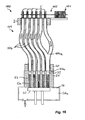
- a device generally designated 100 for producing bristle pads for brushes has according to FIG. 16 a bristle supply 101 and a device 102 for removing individual bristle bundles 5 from the bristle supply 101 and a transport device 103 for transporting the bristle bundles 5 in perforations 22 of a central plate 21 by means of a gas or air flow.
- FIG. 1 An in Fig. 1 shown dividing device for bristle bundles 5, which were removed from a material box by a circular arc or circular disk 6, is below the insertion funnel 3. The falling of the bristle bundle 5 is prevented by a bottom plate 9.
- the distance D1a between circular arc or circular disk 6 and the insertion funnel 3 must be designed so that the bristle bundles 5 can move freely below the insertion funnel 3.
- the sliding plate 8 abuts against the bristle bundle 5.
- the suction hose 1 is held in a hose holding plate 2. While a vacuum is produced through the suction tube 1 by suction (Pf1), the underside of the tube holding plate 2a and the top of the insertion funnel 3a abut against each other.
- Fig.2 the insertion funnel 3 is pushed in the direction of Pf2 down over the nest of clusters 5. A minimum distance D1b between circular arc or circular disk 6 and the insertion funnel 3 must remain.
- Fig. 4 the suction tube 1 is placed over the insertion funnel 3.
- the counterpart 7 releases the clamping in the direction Pf5b and the bottom plate 9 reduces the distance D2a to D2b in the direction of Pf7 and thus pushes the bundles of boron 5 into the suction hose. 1
- Fig. 7 shows the suction process of the bristle bundles 5.
- the bristle bundles 5 are transported in the direction of Pf1 in the holes 22 of the central plate 21 to the baffle plate 23.
- the bristle bundle 5 is divided into two sections: The protruding bundles 5a, which abuts against the bounce plate 23 and the rearward bundle 5b.
- air is permanently withdrawn in the direction Pf12 of the vacuum chamber 26a.
- the air is removed from the central plate 21 in the direction of Pf10 around the baffle plate 23.
- air can additionally be withdrawn from the central plate 21 through the sealing plate 30 in the direction Pf11.
- the guides 27 of the sealing plate 30 ensure that the sealing plate 30 is not twisted.
- the distance D7 between the central plate 21 and the baffle plate 23 is very important. If the distance D7 is set too low, the amount of air is insufficient to pull all the filaments into the central plate. If the distance D7 is set too far, filaments of the bristle bundle 5a can bend over and be sucked in the direction of Pf10 into the vacuum chamber.
- the baffle plate 23 is guided with the guide 28 within the guide 27 of the sealing plate 30.
- the guides could also be done separately.
- the seal 25 between the suction block 26 and the sealing plate 30 and the seal 24 between the baffle plate 23 and sealing plate 30 separates the vacuum chamber 26 a from the bounce plate 23 and the central plate 21.
- a ring ventilation should take place on the underside 20 a of the mold plate 20. This ensures that during the aeration the bristle bundles 5b are not pushed back into the tube 1. Ventilation of the central plate 21 via the hoses 1 and the insertion funnel 3 is also possible, but takes longer.
- the pulsation of the air pressure Pf15 ensures that in the transition region between the bundles 5a and the bundles 5b, the filaments easily slide into each other (FIG. 5c, FIG. Figure 11 ).
- the pulsation of the air pressure Pf15 must be carried out until as many filaments as possible have been pushed into each other.
- Fig. 11 is at the top 21 a of the central plate 21, a pin package with pin guide plate 43 c, individual pins 43 b and pin holder 43 a.
- the counter-plate 42 rests against the central plate 21 again.
- the counter plate 42 of Fig. 10 against another counter plate in Fig. 11 exchanged become.
- Fig. 13 is opposite the Fig. 12 the counter plate 42 replaced by a support plate 45.
- a stop plate 47 At a distance D12 from the support plate 45 is a stop plate 47.
- the pins 43b press the bristle bundles 5d in the support plate 45 until they are present at the stop plate 47.
- the chamfer 46 in the support plate 45 facilitates the insertion of the bristle bundles 5 d into the support plate 45. Repeated joint reciprocation of the pins 43b and the stop plate 47 in the region of the distance D12 results in the bristle bundles 5d being arranged homogeneously within the carrier plate 45.
- bristle bundles 5 shown on the outside have a larger diameter than the other bristle bundles.
- Such a larger bundle of bristles 5 can, for example according to FIG. 16 be composed of the bristle supply 101 by means of a Y-type branched hollow line 104a of two smaller bristle bundles.
- the hollow lines 104, 104 a of the device 100 according to FIG. 16 are hoses made of flexible material, which allows easy and flexible mounting and is inexpensive.
- the central plate 21 is a contour plate 105 and a compressor plate 106 downstream, in which the bristle bundles 5 are reacted by means of the pins 43 b.
- the contour plate 105 has perforations 107, of which a perforation 107a for receiving two bundles of bristles 5 of the central plate 21 is dimensioned. This makes it possible to achieve bristle fields with differently sized bristle subfields, for example areas with elongated bristle sections. From the contour plate 105, the bristle bundles 5 are pushed further directly into a compressor plate 106.
- Their perforations 108 each have a cross-section which is smaller than the corresponding perforation 107 of the contour plate 105, which is particularly evident in FIG FIG.
- the bristle density of the bristle bundles 5 is increased, that is, the individual filaments 109 of the bristle bundles 5 are closer to each other and have a smaller distance from each other.
- the bristle bundle 5 is avoided during the later encapsulation of the attachment ends, that pressed even at higher injection pressures plastic material between the individual filaments and the brush is thus unusable.
- the individual pins 43b with the pin holding plate 43a and the pin guide plate 43c according to FIG. 19 form a common device 110 for passing the bristle bundles 5 from the central plate 21 in the contour plate 105 and the compressor plate 106th
- the bristle bundles 5 are first transferred from the central plate 21 into the contour plate 105, and that the contour plate 105 is moved on to a further processing station, where with a separate transfer device the bristle bundles are transferred into the compacting plate 106.
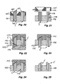
- FIGS. 26 to 29 show a sectional view of a removal plate 111 and the downstream contour plate 105th
- FIG. 26 shows a view from below
- FIG. 28 a view from above.
- the perforations 107 of the contour plate 105 each have different cross sections than the corresponding holes 112 of the removal plate 111.
- round bristle bundles can be transformed into hexagonal, rectangular or elliptical bristle bundles or rectangular round bristle bundles.
- the bristle bundles in the contour plate 105 After the forming of the bristle bundles in the contour plate 105, they can be compacted as described above by further conversion into a compacting plate.
- FIGS. 21 to 25 is shown schematically how the bristle bundles 5 can be profiled after the conversion into the compressor plate 106.
- the contour plate 105 is first removed ( Figure 21 ), so that the bristle bundles 5 only in the compressor plate 106 are held. Subsequently, the utilization-side ends of the bristle bundles 5 become FIG. 22 acted upon by a profile plate 113.
- the bristle bundles 5 are acted on from the opposite side with a counter profiled plate 114. After removal of the counter profile plate 114 (FIG.
- the bristle bundles 5 are cut off on their side remote from the use-side ends with a knife 115 flush with the surface of the compacting plate 106 ( Figure 24 ).
- the profiled bristle bundles 5 can be passed, for example, to a mold plate, which is inserted into an injection mold for encapsulating the fixing side bundle ends and for spraying a brush head or brush body.
- hose systems single hose 1, double hose 52 and triple hose 53, are attached to a mold plate 20. Any number of multiple hoses are conceivable. Due to the multiple hoses, individual bundles can be brought together as shown in direction Pf1.
- the bristle bundle In order to remove the static charge of the bristle bundles, or to clean the bristle bundles or to be able to supply lubricants to the bristle bundles, as indicated by the arrow Pf20, the bristle bundle via an additional line Gases, liquids or powders are supplied.
Claims (21)
- Procédé de fabrication de zones d'implantation de poils destinées à des brosses, en particulier des brosses à dents, des faisceaux de poils (5) étant débités à partir d'une réserve en poils (101), transportés au moyen d'un flux gazeux ou d'un courant d'air (Pf1), puis insérés dans des perforations (22) d'une platine centrale (21), sachant que des filaments de poils (5a, 5b), décalés les uns des autres dans la direction axiale, sont conjointement enfilés à l'intérieur d'une perforation (22) de la platine centrale (21) au moyen de broches enfichables (43b) pouvant être introduites dans les perforations (22) de ladite platine centrale (21) ; et sachant que les faisceaux de poils (5) sont extraits de la platine centrale (21) au moyen de broches enfichables (43b) pouvant être introduites dans les perforations (22) de ladite platine centrale (21), puis sont transférés à une platine de compactage (106) présentant, en vue de recevoir des faisceaux de poils (5), des perforations (108) dont les sections transversales sont respectivement plus petites que la section transversale du faisceau de poils (5) délivré à la perforation considérée, la densité des poils desdits faisceaux de poils (5) s'en trouvant ainsi accrue.
- Procédé selon la revendication 1, dans lequel les faisceaux de poils (5) retenus dans la platine centrale (21) sont tout d'abord transférés à une platine (105) de mise en forme, sachant que des faisceaux de poils individuels (5) de ladite platine centrale (21) sont regroupés, dans ladite platine (105) de mise en forme, en un faisceau de poils commun (5) de plus fort dimensionnement, et/ou la section transversale de faisceaux de poils individuels (5) est modifiée ; et sachant que lesdits faisceaux de poils (5) sont ensuite transférés à la platine de compactage (106) à partir de ladite platine (105) de mise en forme.
- Procédé selon la revendication 1 ou 2, dans lequel plusieurs faisceaux de poils (5), décalés axialement les uns des autres et successivement insérés dans une perforation respective (22) de la platine centrale (21), sont conjointement enfilés, préalablement au transfert à la platine (105) de mise en forme ou à la platine de compactage (106), au moyen de broches enfichables (43b) pouvant être introduites dans les perforations (22) de ladite platine centrale (21).
- Procédé selon l'une des revendications 1 à 3, dans lequel les faisceaux de poils (5) sont profilés à leurs extrémités opérantes, et sont sectionnés à ras à leurs extrémités tournées à l'opposé desdites extrémités opérantes.
- Procédé selon l'une des revendications 1 à 4, dans lequel les faisceaux de poils (5) sont rattachés par fusion à leurs extrémités situées côté rattachement, et/ou sont enrobés de matière plastique par injection, en vue de former une tête de brosse.
- Procédé selon la revendication 5, dans lequel, préalablement au rattachement par fusion ou à l'enrobage par injection, les faisceaux de poils (5) sont transférés à un caisson de moulage à partir de la platine de compactage (106).
- Dispositif de fabrication de zones d'implantation de poils destinées à des brosses, en particulier des brosses à dents, comprenant une réserve en poils (101) et un dispositif (102) conçu pour prélever des faisceaux de poils individuels (5) de ladite réserve en poils (101), ainsi qu'un dispositif de transport (103) affecté au transport desdits faisceaux de poils (5) jusque dans des perforations (22) d'une platine centrale (21), au moyen d'un flux gazeux ou d'un courant d'air (Pf1), en particulier pour la mise en oeuvre du procédé conforme à l'une des revendications 1 à 6, sachant que des broches enfichables (43b) pouvant être introduites dans les perforations (22) de la platine centrale (21) sont prévues pour enfiler conjointement, à l'intérieur d'une perforation (22) de ladite platine centrale (21), des filaments de poils (5a, 5b) décalés les uns des autres dans la direction axiale ; sachant qu'une platine de compactage (106) implantée en aval de ladite platine centrale (21) présente, en vue de recevoir des faisceaux de poils (5), des perforations (108) dont les sections transversales sont respectivement plus petites que la section transversale du faisceau de poils (5) délivré à la perforation considérée ; et sachant qu'un dispositif, doté de broches enfichables (43b) pouvant être introduites dans les perforations (22) de ladite platine centrale (21), est prévu pour la poursuite du transfert desdits faisceaux de poils (5) à ladite platine de compactage (106), à partir de ladite platine centrale (21).
- Dispositif selon la revendication 7, une platine (105) de mise en forme étant implantée en aval de la platine de compactage (106), sachant que ladite platine (105) de mise en forme comporte des perforations (107) dont au moins l'une est dimensionnée pour recevoir au moins deux faisceaux de poils (5) provenant de la platine centrale (21), et/ou présente une section transversale qui diffère de la section transversale de la perforation concordante (22) de ladite platine centrale (21).
- Dispositif selon la revendication 8, un système de transposition étant prévu pour transférer les faisceaux de poils (5) à la platine de compactage (106) à partir de la platine (105) de mise en forme.
- Dispositif selon la revendication 8 ou 9, la platine (105) de mise en forme et la platine de compactage (106) étant agencées en succession dans la direction longitudinale des perforations (107) de ladite platine (105) de mise en forme ; et le dispositif, prévu pour la poursuite du transfert des faisceaux de poils (5) à ladite platine (105) de mise en forme, à partir de la platine centrale (21), est également réalisé en vue de la poursuite du transfert desdits faisceaux de poils (5) à ladite platine de compactage (106).
- Dispositif selon l'une des revendications 7 à 10, le dispositif de transport (103) présentant au moins un conduit creux (104) assigné à un faisceau de poils (5).
- Dispositif selon la revendication 11, le dispositif de transport (103) présentant un nombre de conduits creux (104) adapté au nombre des perforations (22) de la platine centrale (21).
- Dispositif selon la revendication 11 ou 12, les conduits creux (104) se présentant comme des tuyaux souples (1) en matériau flexible.
- Dispositif selon la revendication 11 ou 12, les conduits creux (104) se présentant comme des raccords tubulaires en acier, en acier fin ou en un métal d'un autre type.
- Dispositif selon l'une des revendications 11 à 14, le dispositif de transport (103) comprenant un élément de retenue (20) dédié aux extrémités des conduits creux (104) qui sont tournées à l'opposé de la réserve en poils (101), et une chambre à vide (26a) située à distance dudit élément et affectée à la génération d'une dépression, sachant que la platine centrale (21) peut être interposée entre ledit élément de retenue (20) et ladite chambre à vide (26a) ; et sachant qu'une platine déflectrice (23), remplissant la fonction d'une butée assignée aux faisceaux de poils (5) insérés dans les perforations (22) de ladite platine centrale (21), est logée à l'intérieur de ladite chambre à vide (26a).
- Dispositif selon la revendication 15, la platine déflectrice (23) étant montée mobile, en vue de faire varier la distance entre ladite platine déflectrice (23) et la platine centrale (21).
- Dispositif selon l'une des revendications 7 à 16, les perforations (22, 107, 108) de la platine centrale (21), de la platine (105) de mise en forme, et/ou de la platine de compactage (106), étant respectivement pourvues d'un biseau (22a) côté introduction.
- Dispositif selon l'une des revendications 7 à 17, au moins des perforations individuelles (108) de la platine de compactage (106) étant pratiquées à l'oblique.
- Dispositif selon l'une des revendications 7 à 18, la réserve en poils (101) comportant plusieurs arrivées de matériau, dévolues à un matériau différent constituant les poils.
- Dispositif selon l'une des revendications 7 à 19, un dispositif étant prévu pour le profilage des extrémités opérantes des faisceaux de poils (5).
- Dispositif selon la revendication 20, le dispositif, dévolu au profilage des extrémités opérantes des faisceaux de poils (5), comprenant des broches de profilage ou une platine de profilage (113) conçue(s) pour solliciter lesdites extrémités opérantes des faisceaux de poils (5), et un système de sectionnement (115) conçu pour sectionner les extrémités qui sont tournées à l'opposé desdites extrémités opérantes des faisceaux de poils (5).
Applications Claiming Priority (2)
| Application Number | Priority Date | Filing Date | Title |
|---|---|---|---|
| DE102009013723A DE102009013723A1 (de) | 2009-03-20 | 2009-03-20 | Verfahren und Vorrichtung zum Herstellen und Bereitstellen von Filamentbündel und Borstenfelder |
| PCT/EP2010/001398 WO2010105745A1 (fr) | 2009-03-20 | 2010-03-05 | Procédé et dispositif pour la fabrication de zones de poils pour brosses |
Publications (2)
| Publication Number | Publication Date |
|---|---|
| EP2408334A1 EP2408334A1 (fr) | 2012-01-25 |
| EP2408334B1 true EP2408334B1 (fr) | 2013-04-17 |
Family
ID=42135991
Family Applications (1)
| Application Number | Title | Priority Date | Filing Date |
|---|---|---|---|
| EP10707836.2A Active EP2408334B1 (fr) | 2009-03-20 | 2010-03-05 | Procédé et dispositif de fabrication des ensembles de poils pour des brosses |
Country Status (8)
| Country | Link |
|---|---|
| US (1) | US8814275B2 (fr) |
| EP (1) | EP2408334B1 (fr) |
| JP (1) | JP5619132B2 (fr) |
| KR (1) | KR101670530B1 (fr) |
| CN (1) | CN102361576B (fr) |
| DE (2) | DE102009013723A1 (fr) |
| TW (1) | TWI520699B (fr) |
| WO (1) | WO2010105745A1 (fr) |
Cited By (1)
| Publication number | Priority date | Publication date | Assignee | Title |
|---|---|---|---|---|
| EP2886010A1 (fr) | 2013-12-20 | 2015-06-24 | Ranir GmbH | Dispositif et procédé de fabrication de compartiments de soies |
Families Citing this family (26)
| Publication number | Priority date | Publication date | Assignee | Title |
|---|---|---|---|---|
| DE102010015118A1 (de) * | 2010-04-16 | 2011-10-20 | Zahoransky Ag | Vorrichtung zum Herstellen von Borstenfeldern für Bürsten |
| DE102010055686A1 (de) * | 2010-12-22 | 2012-06-28 | Zahoransky Ag | Vorrichtung zum Herstellen von Borstenfeldern für Bürsten |
| US9357831B2 (en) | 2012-02-24 | 2016-06-07 | Vikan A/S | Hygienic brush head |
| DE102012005311B4 (de) * | 2012-03-19 | 2021-08-12 | Zahoransky Ag | Vorrichtung zum Herstellen von Bürsten oder Borstenwaren, sowie Bürste oder Borstenware |
| DE102013019612B4 (de) * | 2013-01-29 | 2023-12-28 | Zahoransky Ag | Borstenbund-Zuführvorrichtung |
| US10517389B2 (en) | 2013-11-08 | 2019-12-31 | The Procter & Gamble Company | Process and apparatus for creating tufts for tufted article |
| EP2904936B1 (fr) * | 2014-02-06 | 2016-07-20 | The Procter and Gamble Company | Dispositif de fourniture de poils pour la production de brosse et procédé de fourniture |
| EP2921074B1 (fr) * | 2014-03-20 | 2019-10-16 | The Procter and Gamble Company | Dispositif pour le transport de poils pour produire une brosse comprenant une chicane avec des évents de forme conique |
| DE102014010630B3 (de) * | 2014-07-15 | 2015-09-24 | Zahoransky Ag | Verfahren zur Herstellung von Borstenfeldern, Trägerplättchen, Bürste, insbesondere Zahnbürste, sowie Vorrichtung zur Herstellung von Borstenfeldern |
| DE102015109706B4 (de) * | 2014-07-15 | 2019-05-23 | Zahoransky Ag | Trägerplättchen und Bürste, insbesondere Zahnbürste mit Trägerplättchen |
| EP3964101A1 (fr) | 2014-10-23 | 2022-03-09 | Colgate-Palmolive Company | Instrument d´hygiène buccale |
| EP3138438B1 (fr) | 2015-09-03 | 2018-09-05 | The Procter and Gamble Company | Cueilleur de touffe pour un dispositif de prélèvement de touffe d'une machine de fabrication de brosse |
| EP3138436A1 (fr) | 2015-09-03 | 2017-03-08 | The Procter and Gamble Company | Dispositif de ramassage de touffes destiné à une machine de fabrication de brosse |
| BE1023055B1 (de) * | 2015-10-26 | 2016-11-16 | Bart Gerard Boucherie | Vorrichtung und Verfahren zum Erzeugen von Borstenfeldern für Bürsten |
| DE102015015030A1 (de) * | 2015-11-23 | 2017-05-24 | Zahoransky Ag | Vorrichtung zum Herstellen von Borstenfeldern für Bürsten, Baureihe derartiger Vorrichtungen und Verfahren zur Herstellung derartiger Vorrichtungen |
| DE202016101195U1 (de) | 2016-03-04 | 2016-05-12 | V-Air Machines Gmbh | Vorrichtung zum Erzeugen von Borstenfeldern für Bürsten |
| DE102016014653B3 (de) * | 2016-12-08 | 2018-02-08 | Zahoransky Ag | Verfahren zum Stopfen von Bürsten sowie Bürstenstopfmaschine |
| EP3351143B1 (fr) | 2017-01-24 | 2019-11-06 | The Procter and Gamble Company | Cueilleur de touffes destiné à une machine de fabrication de brosse |
| EP3351142B1 (fr) | 2017-01-24 | 2019-10-16 | The Procter and Gamble Company | Dispositif de ramassage de touffes destiné à une machine de fabrication de brosse |
| DE102017114898A1 (de) * | 2017-07-04 | 2019-01-10 | Zahoransky Ag | Bündelentnahmevorrichtung und Bürstenherstellungsmaschine |
| EP3459389B1 (fr) * | 2017-09-21 | 2020-04-22 | Braun GmbH | Procédé et appareil de production de zones de soies pour brosses |
| DE102017125046A1 (de) * | 2017-10-26 | 2019-05-02 | Zahoransky Ag | Verfahren und Vorrichtung zur Herstellung von Borstenfeldern für Bürsten sowie Borstenherstellungsmaschine |
| EP3747310A1 (fr) * | 2019-06-07 | 2020-12-09 | The Procter & Gamble Company | Dispositif de transport de filament |
| KR102275009B1 (ko) * | 2019-07-18 | 2021-07-08 | 주식회사 리앤코 이노베이션 | 칫솔 제조 방법 및 이 방법으로 제조된 칫솔 |
| CN112315182A (zh) * | 2020-09-24 | 2021-02-05 | 安徽瑞洁刷业有限公司 | 一种异形刷生产用加捻机 |
| CN113413005B (zh) * | 2021-06-30 | 2022-08-26 | 慈溪市精诚模具有限公司 | 一种用于刷制品的植毛方法 |
Citations (1)
| Publication number | Priority date | Publication date | Assignee | Title |
|---|---|---|---|---|
| EP2196108A1 (fr) * | 2008-12-10 | 2010-06-16 | Frisetta Kunststoff GmbH | Procédé de fabrication de compartiments de soies à l'aide de formes |
Family Cites Families (29)
| Publication number | Priority date | Publication date | Assignee | Title |
|---|---|---|---|---|
| FR1453829A (fr) * | 1965-03-05 | 1966-07-22 | Procédé de fabrication de brosses et analogues | |
| USRE27455E (en) * | 1970-12-23 | 1972-08-01 | Brush machinery and brush constructions | |
| US4291431A (en) * | 1978-07-14 | 1981-09-29 | Tucel Industries, Inc. | Tufted angular brush consturction |
| EP0149996A3 (fr) * | 1984-01-10 | 1987-10-21 | Schlesinger GmbH & Co. Maschinenbau KG | Procédé et machine pour fabriquer des brosses |
| DE3400510A1 (de) * | 1984-01-10 | 1985-07-18 | Schlesinger GmbH & Co Maschinenbau KG, 3559 Burgwald | Maschine und verfahren zur herstellung von buersten, besen und dergleichen |
| DE3820372C2 (de) * | 1988-06-15 | 1997-07-24 | Coronet Werke Gmbh | Verfahren und Vorrichtung zur Herstellung von Borstenwaren |
| ATE110942T1 (de) * | 1989-06-24 | 1994-09-15 | Frisetta Gmbh | Verfahren und vorrichtung zum herstellen von borstenfeldern oder borstenbündeln. |
| DE4034811C2 (de) * | 1990-11-02 | 2003-08-21 | Zahoransky Anton Gmbh & Co | Bürstenherstellungsmaschine |
| DE4317453A1 (de) * | 1993-05-26 | 1994-12-01 | Schiffer Fa M & C | Verfahren zum Konfigurieren von Borstenbündeln |
| DE4330171C2 (de) | 1993-09-07 | 2003-03-27 | Zahoransky Anton Gmbh & Co | Verfahren zum Herstellen von Bürsten sowie Bürstenherstellungsmaschine zur Durchführung des Verfahrens |
| GB2287901B (en) * | 1994-03-29 | 1998-05-06 | Boucherie Nv G B | A brush making machine |
| DE4420757A1 (de) | 1994-06-15 | 1995-12-21 | Zahoransky Anton Gmbh & Co | Bürstenherstellungsmaschine |
| EP0843524B1 (fr) * | 1994-12-01 | 2001-10-24 | The Procter & Gamble Company | Brosse a dents dotee de poils supplementaires plus longs |
| US5683145A (en) * | 1995-08-04 | 1997-11-04 | G.B. Boucherie N.V. | Brush finishing machine and a method of profiling toothbrush bristle tufts |
| JPH09252845A (ja) * | 1996-03-22 | 1997-09-30 | Lion Corp | ブラシの製造方法 |
| DE29712554U1 (de) * | 1997-07-16 | 1998-11-19 | Zahoransky Anton Gmbh & Co | Bürstenherstellungsmaschine |
| DE69915180T2 (de) * | 1998-07-14 | 2004-12-30 | Firma G.B. Boucherie N.V. | Verfahren zum Herstellen von Bürsten sowie Bürstenherstellungsmaschine zur Durchführung dieses Verfahrens |
| JP2000060643A (ja) * | 1998-08-26 | 2000-02-29 | Lion Corp | 歯ブラシの製造方法 |
| JP4132744B2 (ja) * | 2000-08-23 | 2008-08-13 | 花王株式会社 | ブラシの製造方法及び装置 |
| DE10108339A1 (de) * | 2001-02-21 | 2002-08-29 | Schiffer Fa M & C | Verfahren zur Herstellung von Bürsten im Wege des Spritzgießens |
| US6666524B2 (en) * | 2001-05-23 | 2003-12-23 | The Gillette Company | End-rounding devices and methods for end-rounding |
| DE10126631A1 (de) | 2001-05-31 | 2002-12-05 | Schiffer Fa M & C | Verfahren und Vorrichtung zum Herstellen einer Bürste |
| JP4079668B2 (ja) * | 2002-02-25 | 2008-04-23 | 花王株式会社 | ブラシの製造方法 |
| JP4173677B2 (ja) | 2002-02-25 | 2008-10-29 | 花王株式会社 | ブラシの製造方法 |
| MXPA04007627A (es) * | 2002-12-03 | 2004-11-10 | Young Jun Kwon | Cepillo de dientes que tiene cerdas en forma de aguja ahusadas en un extremo y metodo de fabricacion del mismo. |
| US7921499B2 (en) * | 2004-07-12 | 2011-04-12 | Trisa Holding Ag | Method and device for producing a toothbrush by the two-component or multi-component injection-molding process |
| CN100362955C (zh) * | 2005-11-23 | 2008-01-23 | 饶薇 | 异孔形毛刷植毛机 |
| BE1017222A3 (nl) * | 2006-07-12 | 2008-05-06 | Frima G B Boucherie Nv | Werkwijze voor het vervaardigen van borstels en inrichting daarbij toegepast. |
| EP2420157B1 (fr) * | 2010-08-18 | 2016-03-30 | Trisa Holding AG | Brosse à dents dotée d'une topographie particulière des soies |
-
2009
- 2009-03-20 DE DE102009013723A patent/DE102009013723A1/de not_active Withdrawn
-
2010
- 2010-03-05 DE DE202010015966U patent/DE202010015966U1/de not_active Expired - Lifetime
- 2010-03-05 EP EP10707836.2A patent/EP2408334B1/fr active Active
- 2010-03-05 KR KR1020117017764A patent/KR101670530B1/ko active IP Right Grant
- 2010-03-05 US US13/256,129 patent/US8814275B2/en active Active
- 2010-03-05 WO PCT/EP2010/001398 patent/WO2010105745A1/fr active Application Filing
- 2010-03-05 JP JP2012500106A patent/JP5619132B2/ja active Active
- 2010-03-05 CN CN201080012593.3A patent/CN102361576B/zh active Active
- 2010-03-17 TW TW099107734A patent/TWI520699B/zh active
Patent Citations (1)
| Publication number | Priority date | Publication date | Assignee | Title |
|---|---|---|---|---|
| EP2196108A1 (fr) * | 2008-12-10 | 2010-06-16 | Frisetta Kunststoff GmbH | Procédé de fabrication de compartiments de soies à l'aide de formes |
Cited By (2)
| Publication number | Priority date | Publication date | Assignee | Title |
|---|---|---|---|---|
| EP2886010A1 (fr) | 2013-12-20 | 2015-06-24 | Ranir GmbH | Dispositif et procédé de fabrication de compartiments de soies |
| EP2886010B1 (fr) | 2013-12-20 | 2018-02-14 | Ranir GmbH | Dispositif et procédé de fabrication de compartiments de soies |
Also Published As
| Publication number | Publication date |
|---|---|
| TWI520699B (zh) | 2016-02-11 |
| US8814275B2 (en) | 2014-08-26 |
| DE202010015966U1 (de) | 2011-04-14 |
| US20120013169A1 (en) | 2012-01-19 |
| DE102009013723A1 (de) | 2010-09-23 |
| CN102361576A (zh) | 2012-02-22 |
| KR20120006972A (ko) | 2012-01-19 |
| CN102361576B (zh) | 2014-01-15 |
| KR101670530B1 (ko) | 2016-11-09 |
| EP2408334A1 (fr) | 2012-01-25 |
| TW201039771A (en) | 2010-11-16 |
| JP2012520698A (ja) | 2012-09-10 |
| JP5619132B2 (ja) | 2014-11-05 |
| WO2010105745A1 (fr) | 2010-09-23 |
Similar Documents
| Publication | Publication Date | Title |
|---|---|---|
| EP2408334B1 (fr) | Procédé et dispositif de fabrication des ensembles de poils pour des brosses | |
| EP0405204B1 (fr) | Dispositif et procédé pour façonner une répartition de soies ou une touffe de soies | |
| EP2557961B1 (fr) | Dispositif pour fabriquer des zones de soies pour des brosses | |
| EP3169191B1 (fr) | Procédé de fixation de faisceaux de poils constitués de filaments de poils sur une plaquette de support | |
| EP0346646B2 (fr) | Dispositif et procédé pour fabriquer des brosses | |
| EP1158880B1 (fr) | Procede et dispositif pour produire des articles de brosserie et articles de brosserie ainsi obtenus | |
| EP0149996A2 (fr) | Procédé et machine pour fabriquer des brosses | |
| EP1864588A2 (fr) | Brosse à dents et procédé destiné à sa fabrication | |
| DE102010055686A1 (de) | Vorrichtung zum Herstellen von Borstenfeldern für Bürsten | |
| EP3223650A1 (fr) | Procédé et dispositif de fabrication d'un nettoyeur inter-dentaire | |
| EP3379972B1 (fr) | Dispositif de production de zones de poils de brosses, gamme de fabrication de tels dispositifs et procédé de fabrication de tels dispositifs | |
| EP3367843B1 (fr) | Dispositif et procédé de production de champs de poils pour des brosses | |
| EP2196108B1 (fr) | Procédé de fabrication de compartiments de soies à l'aide de formes | |
| WO1999001055A1 (fr) | Dispositif de moulage par injection | |
| DE3920769C2 (fr) | ||
| DE102012010415B4 (de) | Verfahren zum Herstellen von Bürsten, Borstenträger sowie Bürste | |
| DE102006057241A1 (de) | Maschine zum Herstellen von gedrehten Bürsten | |
| EP3430944B1 (fr) | Procédé et dispositif de fabrication de faisceaux de poils | |
| EP1522234B1 (fr) | Procédé pour fabriquer des brosses, en particulier des brosses à dents | |
| DE102017104451B4 (de) | Vorrichtung zum Erzeugen von Borstenfeldern für Bürsten | |
| DE3405001A1 (de) | Verfahren zur herstellung von buersten, besen und dergleichen | |
| DE10108339A1 (de) | Verfahren zur Herstellung von Bürsten im Wege des Spritzgießens | |
| DE19536759C2 (de) | Verfahren zur Herstellung eines Rohrs | |
| DE10354774A1 (de) | Verfahren und Vorrichtung zur Herstellung von Bürsten sowie danach hergestellte Bürste | |
| DE10328445B4 (de) | Verfahren und Vorrichtung zur Herstellung von gedrehten Bürsten |
Legal Events
| Date | Code | Title | Description |
|---|---|---|---|
| PUAI | Public reference made under article 153(3) epc to a published international application that has entered the european phase |
Free format text: ORIGINAL CODE: 0009012 |
|
| 17P | Request for examination filed |
Effective date: 20111020 |
|
| AK | Designated contracting states |
Kind code of ref document: A1 Designated state(s): AT BE BG CH CY CZ DE DK EE ES FI FR GB GR HR HU IE IS IT LI LT LU LV MC MK MT NL NO PL PT RO SE SI SK SM TR |
|
| DAX | Request for extension of the european patent (deleted) | ||
| GRAP | Despatch of communication of intention to grant a patent |
Free format text: ORIGINAL CODE: EPIDOSNIGR1 |
|
| GRAS | Grant fee paid |
Free format text: ORIGINAL CODE: EPIDOSNIGR3 |
|
| GRAP | Despatch of communication of intention to grant a patent |
Free format text: ORIGINAL CODE: EPIDOSNIGR1 |
|
| GRAA | (expected) grant |
Free format text: ORIGINAL CODE: 0009210 |
|
| AK | Designated contracting states |
Kind code of ref document: B1 Designated state(s): AT BE BG CH CY CZ DE DK EE ES FI FR GB GR HR HU IE IS IT LI LT LU LV MC MK MT NL NO PL PT RO SE SI SK SM TR |
|
| REG | Reference to a national code |
Ref country code: GB Ref legal event code: FG4D Free format text: NOT ENGLISH |
|
| REG | Reference to a national code |
Ref country code: CH Ref legal event code: EP |
|
| REG | Reference to a national code |
Ref country code: IE Ref legal event code: FG4D Free format text: LANGUAGE OF EP DOCUMENT: GERMAN |
|
| REG | Reference to a national code |
Ref country code: AT Ref legal event code: REF Ref document number: 606699 Country of ref document: AT Kind code of ref document: T Effective date: 20130515 |
|
| REG | Reference to a national code |
Ref country code: DE Ref legal event code: R096 Ref document number: 502010002996 Country of ref document: DE Effective date: 20130606 |
|
| REG | Reference to a national code |
Ref country code: LT Ref legal event code: MG4D |
|
| REG | Reference to a national code |
Ref country code: NL Ref legal event code: VDEP Effective date: 20130417 |
|
| PG25 | Lapsed in a contracting state [announced via postgrant information from national office to epo] |
Ref country code: SE Free format text: LAPSE BECAUSE OF FAILURE TO SUBMIT A TRANSLATION OF THE DESCRIPTION OR TO PAY THE FEE WITHIN THE PRESCRIBED TIME-LIMIT Effective date: 20130417 Ref country code: LT Free format text: LAPSE BECAUSE OF FAILURE TO SUBMIT A TRANSLATION OF THE DESCRIPTION OR TO PAY THE FEE WITHIN THE PRESCRIBED TIME-LIMIT Effective date: 20130417 Ref country code: ES Free format text: LAPSE BECAUSE OF FAILURE TO SUBMIT A TRANSLATION OF THE DESCRIPTION OR TO PAY THE FEE WITHIN THE PRESCRIBED TIME-LIMIT Effective date: 20130728 Ref country code: FI Free format text: LAPSE BECAUSE OF FAILURE TO SUBMIT A TRANSLATION OF THE DESCRIPTION OR TO PAY THE FEE WITHIN THE PRESCRIBED TIME-LIMIT Effective date: 20130417 Ref country code: IS Free format text: LAPSE BECAUSE OF FAILURE TO SUBMIT A TRANSLATION OF THE DESCRIPTION OR TO PAY THE FEE WITHIN THE PRESCRIBED TIME-LIMIT Effective date: 20130817 Ref country code: SI Free format text: LAPSE BECAUSE OF FAILURE TO SUBMIT A TRANSLATION OF THE DESCRIPTION OR TO PAY THE FEE WITHIN THE PRESCRIBED TIME-LIMIT Effective date: 20130417 Ref country code: PT Free format text: LAPSE BECAUSE OF FAILURE TO SUBMIT A TRANSLATION OF THE DESCRIPTION OR TO PAY THE FEE WITHIN THE PRESCRIBED TIME-LIMIT Effective date: 20130819 Ref country code: NO Free format text: LAPSE BECAUSE OF FAILURE TO SUBMIT A TRANSLATION OF THE DESCRIPTION OR TO PAY THE FEE WITHIN THE PRESCRIBED TIME-LIMIT Effective date: 20130717 Ref country code: GR Free format text: LAPSE BECAUSE OF FAILURE TO SUBMIT A TRANSLATION OF THE DESCRIPTION OR TO PAY THE FEE WITHIN THE PRESCRIBED TIME-LIMIT Effective date: 20130718 |
|
| PG25 | Lapsed in a contracting state [announced via postgrant information from national office to epo] |
Ref country code: CY Free format text: LAPSE BECAUSE OF FAILURE TO SUBMIT A TRANSLATION OF THE DESCRIPTION OR TO PAY THE FEE WITHIN THE PRESCRIBED TIME-LIMIT Effective date: 20130417 Ref country code: LV Free format text: LAPSE BECAUSE OF FAILURE TO SUBMIT A TRANSLATION OF THE DESCRIPTION OR TO PAY THE FEE WITHIN THE PRESCRIBED TIME-LIMIT Effective date: 20130417 Ref country code: HR Free format text: LAPSE BECAUSE OF FAILURE TO SUBMIT A TRANSLATION OF THE DESCRIPTION OR TO PAY THE FEE WITHIN THE PRESCRIBED TIME-LIMIT Effective date: 20130417 Ref country code: BG Free format text: LAPSE BECAUSE OF FAILURE TO SUBMIT A TRANSLATION OF THE DESCRIPTION OR TO PAY THE FEE WITHIN THE PRESCRIBED TIME-LIMIT Effective date: 20130717 Ref country code: PL Free format text: LAPSE BECAUSE OF FAILURE TO SUBMIT A TRANSLATION OF THE DESCRIPTION OR TO PAY THE FEE WITHIN THE PRESCRIBED TIME-LIMIT Effective date: 20130417 |
|
| PG25 | Lapsed in a contracting state [announced via postgrant information from national office to epo] |
Ref country code: SK Free format text: LAPSE BECAUSE OF FAILURE TO SUBMIT A TRANSLATION OF THE DESCRIPTION OR TO PAY THE FEE WITHIN THE PRESCRIBED TIME-LIMIT Effective date: 20130417 Ref country code: DK Free format text: LAPSE BECAUSE OF FAILURE TO SUBMIT A TRANSLATION OF THE DESCRIPTION OR TO PAY THE FEE WITHIN THE PRESCRIBED TIME-LIMIT Effective date: 20130417 Ref country code: CZ Free format text: LAPSE BECAUSE OF FAILURE TO SUBMIT A TRANSLATION OF THE DESCRIPTION OR TO PAY THE FEE WITHIN THE PRESCRIBED TIME-LIMIT Effective date: 20130417 Ref country code: EE Free format text: LAPSE BECAUSE OF FAILURE TO SUBMIT A TRANSLATION OF THE DESCRIPTION OR TO PAY THE FEE WITHIN THE PRESCRIBED TIME-LIMIT Effective date: 20130417 |
|
| PLBE | No opposition filed within time limit |
Free format text: ORIGINAL CODE: 0009261 |
|
| STAA | Information on the status of an ep patent application or granted ep patent |
Free format text: STATUS: NO OPPOSITION FILED WITHIN TIME LIMIT |
|
| PG25 | Lapsed in a contracting state [announced via postgrant information from national office to epo] |
Ref country code: IT Free format text: LAPSE BECAUSE OF FAILURE TO SUBMIT A TRANSLATION OF THE DESCRIPTION OR TO PAY THE FEE WITHIN THE PRESCRIBED TIME-LIMIT Effective date: 20130417 Ref country code: NL Free format text: LAPSE BECAUSE OF FAILURE TO SUBMIT A TRANSLATION OF THE DESCRIPTION OR TO PAY THE FEE WITHIN THE PRESCRIBED TIME-LIMIT Effective date: 20130417 Ref country code: RO Free format text: LAPSE BECAUSE OF FAILURE TO SUBMIT A TRANSLATION OF THE DESCRIPTION OR TO PAY THE FEE WITHIN THE PRESCRIBED TIME-LIMIT Effective date: 20130417 |
|
| 26N | No opposition filed |
Effective date: 20140120 |
|
| REG | Reference to a national code |
Ref country code: DE Ref legal event code: R097 Ref document number: 502010002996 Country of ref document: DE Effective date: 20140120 |
|
| PG25 | Lapsed in a contracting state [announced via postgrant information from national office to epo] |
Ref country code: LU Free format text: LAPSE BECAUSE OF FAILURE TO SUBMIT A TRANSLATION OF THE DESCRIPTION OR TO PAY THE FEE WITHIN THE PRESCRIBED TIME-LIMIT Effective date: 20140305 |
|
| REG | Reference to a national code |
Ref country code: CH Ref legal event code: PL |
|
| GBPC | Gb: european patent ceased through non-payment of renewal fee |
Effective date: 20140305 |
|
| REG | Reference to a national code |
Ref country code: FR Ref legal event code: ST Effective date: 20141128 |
|
| PG25 | Lapsed in a contracting state [announced via postgrant information from national office to epo] |
Ref country code: CH Free format text: LAPSE BECAUSE OF NON-PAYMENT OF DUE FEES Effective date: 20140331 Ref country code: FR Free format text: LAPSE BECAUSE OF NON-PAYMENT OF DUE FEES Effective date: 20140331 Ref country code: LI Free format text: LAPSE BECAUSE OF NON-PAYMENT OF DUE FEES Effective date: 20140331 Ref country code: GB Free format text: LAPSE BECAUSE OF NON-PAYMENT OF DUE FEES Effective date: 20140305 |
|
| PG25 | Lapsed in a contracting state [announced via postgrant information from national office to epo] |
Ref country code: MT Free format text: LAPSE BECAUSE OF FAILURE TO SUBMIT A TRANSLATION OF THE DESCRIPTION OR TO PAY THE FEE WITHIN THE PRESCRIBED TIME-LIMIT Effective date: 20130417 |
|
| PG25 | Lapsed in a contracting state [announced via postgrant information from national office to epo] |
Ref country code: SM Free format text: LAPSE BECAUSE OF FAILURE TO SUBMIT A TRANSLATION OF THE DESCRIPTION OR TO PAY THE FEE WITHIN THE PRESCRIBED TIME-LIMIT Effective date: 20130417 |
|
| REG | Reference to a national code |
Ref country code: AT Ref legal event code: MM01 Ref document number: 606699 Country of ref document: AT Kind code of ref document: T Effective date: 20150305 |
|
| PG25 | Lapsed in a contracting state [announced via postgrant information from national office to epo] |
Ref country code: MC Free format text: LAPSE BECAUSE OF FAILURE TO SUBMIT A TRANSLATION OF THE DESCRIPTION OR TO PAY THE FEE WITHIN THE PRESCRIBED TIME-LIMIT Effective date: 20130417 |
|
| PG25 | Lapsed in a contracting state [announced via postgrant information from national office to epo] |
Ref country code: HU Free format text: LAPSE BECAUSE OF FAILURE TO SUBMIT A TRANSLATION OF THE DESCRIPTION OR TO PAY THE FEE WITHIN THE PRESCRIBED TIME-LIMIT; INVALID AB INITIO Effective date: 20100305 Ref country code: TR Free format text: LAPSE BECAUSE OF FAILURE TO SUBMIT A TRANSLATION OF THE DESCRIPTION OR TO PAY THE FEE WITHIN THE PRESCRIBED TIME-LIMIT Effective date: 20130417 |
|
| PG25 | Lapsed in a contracting state [announced via postgrant information from national office to epo] |
Ref country code: AT Free format text: LAPSE BECAUSE OF NON-PAYMENT OF DUE FEES Effective date: 20150305 |
|
| PG25 | Lapsed in a contracting state [announced via postgrant information from national office to epo] |
Ref country code: MK Free format text: LAPSE BECAUSE OF FAILURE TO SUBMIT A TRANSLATION OF THE DESCRIPTION OR TO PAY THE FEE WITHIN THE PRESCRIBED TIME-LIMIT Effective date: 20130417 |
|
| PGFP | Annual fee paid to national office [announced via postgrant information from national office to epo] |
Ref country code: IE Payment date: 20230320 Year of fee payment: 14 |
|
| PGFP | Annual fee paid to national office [announced via postgrant information from national office to epo] |
Ref country code: BE Payment date: 20230321 Year of fee payment: 14 |
|
| PGFP | Annual fee paid to national office [announced via postgrant information from national office to epo] |
Ref country code: DE Payment date: 20230420 Year of fee payment: 14 |
|
| PGFP | Annual fee paid to national office [announced via postgrant information from national office to epo] |
Ref country code: IE Payment date: 20240319 Year of fee payment: 15 |