EP2407366B1 - Kabeltransportsystemschalter und Kabeltransportsystem mit dem Schalter - Google Patents
Kabeltransportsystemschalter und Kabeltransportsystem mit dem Schalter Download PDFInfo
- Publication number
- EP2407366B1 EP2407366B1 EP11174071.8A EP11174071A EP2407366B1 EP 2407366 B1 EP2407366 B1 EP 2407366B1 EP 11174071 A EP11174071 A EP 11174071A EP 2407366 B1 EP2407366 B1 EP 2407366B1
- Authority
- EP
- European Patent Office
- Prior art keywords
- straight rail
- switch
- rail
- straight
- track
- Prior art date
- Legal status (The legal status is an assumption and is not a legal conclusion. Google has not performed a legal analysis and makes no representation as to the accuracy of the status listed.)
- Active
Links
Images
Classifications
-
- B—PERFORMING OPERATIONS; TRANSPORTING
- B61—RAILWAYS
- B61B—RAILWAY SYSTEMS; EQUIPMENT THEREFOR NOT OTHERWISE PROVIDED FOR
- B61B9/00—Tramway or funicular systems with rigid track and cable traction
Definitions
- the present invention relates to a cable transportation system switch.
- the present invention relates to a switch for a cable transportation system comprising transportation units moved by at least one hauling cable along a track defined by pairs of parallel rails.
- Cable transportation systems of the above type are described in documents CH 671,929 ; AT 404,010 ; US 5,582,109 ; EP 687,607 ; AT 405,269 ; EP 1,077,167 ; EP 1,088,729 ; IT 1,313,914 ; IT 1,317,169 ; IT 1,316,131 ; IT 1,326,531 ; WO 08/129,019 ; WO 2009/019,259 ; WO 2009/053,485 .
- the tracks of cable transportation systems of the above type sometimes have forks.
- One particular type is that in which the track forks into two at a stop station for two transportation units travelling in opposite directions.
- cable transportation system tracks may comprise two-way single-rail portions, and two-rail portions along which the transportation units pass one another in opposite directions.
- the system comprises two respective hauling cables operated in opposite directions.
- the hauling cables extend parallel to the track, between the rails, and are connected to the transportation units by clamps integral with the units. Therefore, in addition to ensuring continuity of the track, the switches must also be designed to avoid interfering with the hauling cable/s and clamps.
- switch for cable transportation systems of the above type is described in Patent IT 1,326,531 , in which the switch comprises a track portion defined by two parallel curved rails extending along respective arcs, mounted on a pivot, and designed to connect different branches of the track, depending on the angular position of the pivot.
- Another object of the present invention to provide a cable transportation system switch featuring a small moving part.
- Another object of the present invention to provide a cable transportation system switch that is easy to move.
- a cable transportation system switch comprising:
- switching is performed by simply moving the third straight rail, which, combined with the first straight rail, at least partly defines one branch of the track, and, combined with the second straight rail, at least partly defines a further branch of the track.
- This switch configuration has a relatively compact, lightweight moving part, and provides for faster switching between the first and second operating positions.
- the first and second straight rail have a first and second contoured portion respectively; and the third straight rail has a contoured end designed to form a joint with the first and second contoured portion.
- the above design of the first, second and third straight rail ensures the continuity of the track.
- the present invention also relates to a cable transportation system.
- a cable transportation system comprising:
- Number 1 in Figure 1 indicates as a whole a rail-mounted cable transportation system.
- Cable transportation system 1 comprises a track 2; a stop station 3 along track 2; and two transportation units 4.
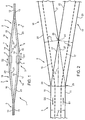
- Track 2 is defined by parallel rails with a gauge S ( Figure 2 ), and comprises two series branches 5 and 6, and two parallel branches 7 and 8 connected to branches 5 and 6 by two switches 9.
- Cable transportation system 1 comprises two hauling cables 16 and 17 extending along track 2, between the rails, and operated in opposite directions D2 and D1 respectively.
- both hauling cables 16 and 17 extend along branches 5 and 6, whereas only hauling cable 16 extends along branch 7, and only hauling cable 17 extends along branch 8.
- each switch 9 comprises two diverging branches (or converging branches, depending on the travelling direction) 18 and 19 for connecting branch 5 (or branch 6) to branches 7 and 8 ( Figure 1 ).
- Branches 18 and 19 form a 12° angle, though the present invention also applies to switches with branches 18 and 19 forming angles of 0° to 45°.
- Branch 18 comprises two straight parallel rails 20 and 21, and branch 19 comprises two straight parallel rails 22 and 23.
- Straight rail 20 is connected to rail 10 at a connecting point 24; straight rail 23 is connected to rail 11 at a connecting point 25; whereas straight rails 21 and 22 converge and contact one another at a vertex 26.
- Switch 9 comprises a movable straight rail 27 mounted for rotation at vertex 26, and movable selectively into a first operating position shown by the continuous line in Figure 2 , and a second operating position shown by the dash line in Figure 2 .
- the dot-and-dash line shows straight rail 27 in an intermediate position between the first and second operating position.
- straight rail 27 In the first operating position, straight rail 27 is parallel to straight rail 23, aligned with straight rail 22, connected to rail 10, and contacting straight rail 20.
- straight rail 27 In the second operating position, straight rail 27 is parallel to straight rail 20, aligned with straight rail 21, connected to rail 11, and contacting straight rail 23.
- Straight rail 27 rotates about an axis A1, which is perpendicular to the plane of straight rails 20, 23, 27, is located close to vertex 26, and is the same distance, substantially equal to gauge S of track 2, from rails 20 and 23.
- straight rail 27 has a hinged end 28 adjacent to straight rails 21, 22 at vertex 26 and in the shape of an arc centred about axis A1; and a free end 29 designed to form a joint with straight rails 20 and 23 at respective connecting points 24 and 25, which are spaced apart by a distance substantially equal to the gauge S of track 2.
- the free end 29 of straight rail 27 thus moves along an arc, which is centred about axis A1, is defined at the ends by connecting points 24 and 25, and has a chord substantially equal in length to gauge S.
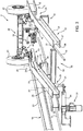
- Each switch 9 comprises a supporting structure 30 for supporting straight rail 27; and an actuating device 31 for operating straight rail 27.
- Supporting structure 30 comprises a guide 32 located beneath and for guiding straight rail 27 between the first and second operating positions; and two supporting members 33 beneath respective connecting points 24 and 25.
- Actuating device 31 comprises a linear actuator 34 connected to supporting structure 30 and to straight rail 27, between ends 28 and 29.
- actuating device comprises a rotating actuator connected to the rail by means of a crank having one end engaged in a slit made in the rail.
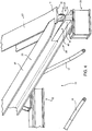
- Each of rails 10, 11, 12, 13, 14, 15, 20, 21, 22, 23, 27 ( Figure 1 ) is defined by a beam - in the example shown, an HEB beam - comprising an upper flange 35 and a lower flange 36 parallel to each other and connected by a web 37.
- upper flange 35 and web 37 define respective rolling tracks for transportation units 4, as shown more clearly in Figure 3 .
- Number 38 in Figure 3 indicates an axle forming part of a transportation unit 4, and which comprises a frame 39; two steering assemblies 40 connected to frame 39; two wheels 41 connected to respective steering assemblies 40; and a clamp 42 for selectively gripping and releasing hauling cable 16.
- Each steering assembly 40 comprises a steering trolley 43 designed to roll along the track defined by web 37, and to steer a respective wheel 41.
- Rail 10 and straight rail 20 have contoured portions at connecting point 24 for forming a joint with the free end 29 of straight rail 27; rail 11 and straight rail 23 have contoured portions at connecting point 25 for also forming a joint with the free end 29 of straight rail 27; and the free end 29 of straight rail 27 is shaped to form the joints with the respective contoured portions at connecting points 24 and 25, and to connect the rolling tracks.
- the bottom parts of rail 10 and straight rail 20 are removed along the contoured portions at connecting point 24, and the bottom parts of rail 11 and straight rail 23 are removed along the contoured portions at connecting point 25. More specifically, lower flange 36 is removed completely, and roughly half the height of web 37 is removed. Conversely, the top part of straight rail 27 is removed at free end 29. That is, upper flange 35 is removed completely, and roughly half the height of web 37 is removed at free end 29.
- the free end 29 of straight rail 27 is also designed to form a curved path at both connecting points 24 and 25.
- straight rail 27 comprises two connecting members 44 located symmetrically on opposite sides of web 37 at free end 29.
- One connecting member 44 comprises a curved face 45 tangent to web 37 of straight rail 27 and to web 37 of rail 10 at connecting point 24; and the other connecting member 44 comprises a curved face 45 tangent to web 37 of straight rail 27 and to web 37 of rail 11 at connecting point 25.
- the switch according to the present invention has numerous advantages.
- the moving part of the switch is relatively compact and lightweight, and only has to move a relatively short distance, so the movable straight rail can be moved quickly between the first and second operating position.
- the design of the free end of the movable straight rail forms smooth rolling tracks for the steering trolleys, with no sharp change in direction at the switch, thus improving passenger comfort and the stability of the transportation unit.
Landscapes
- Engineering & Computer Science (AREA)
- Transportation (AREA)
- Mechanical Engineering (AREA)
- Electric Cable Arrangement Between Relatively Moving Parts (AREA)
- Platform Screen Doors And Railroad Systems (AREA)
- Ropes Or Cables (AREA)
- Gas-Insulated Switchgears (AREA)
- Chain Conveyers (AREA)
Claims (11)
- Kabeltransportsystemschalter (9), der umfasst:- eine erste gerade Schiene (20);- eine zweite gerade Schiene (23), die einen Winkel von mehr als 0° und weniger als 45° mit der ersten geraden Schiene (20) bildet;- eine dritte gerade Schiene (27), die zwischen der ersten und zweiten geraden Schiene (20, 23) angeordnet ist und selektiv zwischen einer ersten Betriebsposition, in der sie die erste gerade Schiene (20) kontaktiert und parallel zu der zweiten geraden Schiene (23) ist, und einer zweiten Betriebsposition, in der sie die zweite gerade Schiene (23) kontaktiert und parallel zu der ersten geraden Schiene (20) ist, beweglich ist;- eine Haltestruktur (30) zum Halten der dritten geraden Schiene (27); und- eine Betätigungsvorrichtung (31) zum Betreiben der dritten geraden Schiene (27).
- Schalter nach Anspruch 1, wobei die dritte gerade Schiene (27) sich um eine Achse (A1) senkrecht zu der Ebene der ersten, zweiten und dritten geraden Schiene (20, 23, 27) dreht.
- Schalter nach Anspruch 2, wobei die Achse (A1) von der ersten und zweiten geraden Schiene (20, 23) den gleichen Abstand hat.
- Schalter nach Anspruch 2 oder 3, der umfasst:- eine vierte gerade Schiene (21) parallel zu der ersten geraden Schiene (20); und- eine fünfte gerade Schiene (22) parallel zu der zweiten geraden Schiene (23);wobei die vierte und fünfte gerade Schiene (21, 22) nahe der Achse (A1) einen Scheitel (26) bilden.
- Schalter nach einem der vorangehenden Ansprüche, der eine Betätigungsvorrichtung (31) umfasst, die mit der dritten geraden Schiene (27) verbunden ist, um die dritte gerade Schiene (27) zwischen der ersten und zweiten Betriebsposition zu bewegen.
- Schalter nach Anspruch 4, wobei die Betätigungsvorrichtung (31) einen linearen Aktuator (34) umfasst, der zwischen den zwei Enden (28, 29) der dritten geraden Schiene (27) angeordnet ist.
- Schalter nach einem der vorangehenden Ansprüche, wobei die erste und zweite gerade Schiene (20, 23) jeweils einen ersten und zweiten profilierten Abschnitt haben; und die dritte gerade Schiene (27) ein freies Ende (29) hat, das konstruiert ist, um eine Verbindung mit dem zweiten profilierten Abschnitt zu bilden.
- Schalter nach Anspruch 7, wobei die erste, zweite und dritte Schiene (20, 23, 27) jeweils einen oberen Abschnitt und einen unteren Abschnitt haben; die unteren Abschnitte der ersten und zweiten geraden Schiene (20, 23) jeweils entlang des ersten und zweiten profilierten Abschnitts entfernt sind; und der oberste Abschnitt des freien Endes (29) der dritten geraden Schiene (27) entfernt ist, so dass die erste und dritte gerade Schiene (20, 27) einander in der ersten Betriebsposition überlappen und die zweite und dritte gerade Schiene (23, 27) in der zweiten Betriebsposition überlappen.
- Schalter nach Anspruch 7 oder 8, wobei die erste, zweite und dritte gerade Schiene (20, 23, 27) jeweils einen oberen Flansch (35) aufweisen, der eine Rollspur für eine Transporteinheit (4) definiert; die oberen Flansche (35) der ersten und zweiten geraden Schiene (20, 23) jeweils einen Ausschnitt entlang des jeweiligen ersten und zweiten profilierten Abschnitts haben; und der obere Flansch (35) an dem freien Ende (29) der dritten geraden Schiene (27) eine komplementäre Form in der Form der Ausschnitte in der ersten und zweiten geraden Schiene (20, 23) hat.
- Schalter nach einem der Ansprüche 7 bis 9, wobei die erste, zweite und dritte gerade Schiene (20, 23, 27) jeweils eine Bahn (37) umfassen, die eine Rollspur für einen Lenkwagen (43) einer Transporteinheit (4) umfasst; die dritte gerade Schiene (27) ein erstes und zweites Führungselement (44) umfasst, das auf entgegengesetzten Seiten der Bahn (37) der dritten geraden Schiene (27) symmetrisch angeordnet ist, um jeweilige gekrümmte Wege zu definieren, die die Bahn (37) der dritten geraden Schiene (27) berühren.
- Kabeltransportsystem, das umfasst:- wenigstens eine Transporteinheit (4) mit Rädern (41) und Lenkwagen (43) zum Lenken der Räder (41);- eine Spur (2), entlang welcher die Transporteinheit (4) läuft;- zwei Zugseile (16, 17), die mit der Transporteinheit in Eingriff bringbar sind; und- einen Schalter (9), der entlang der Spur (2) angeordnet ist, nach einem der vorangehenden Ansprüche.
Applications Claiming Priority (1)
| Application Number | Priority Date | Filing Date | Title |
|---|---|---|---|
| ITMI2010A001297A IT1401120B1 (it) | 2010-07-14 | 2010-07-14 | Scambio per impianto di trasporto a fune e impianto di trasporto a fune comprendente tale scambio. |
Publications (4)
| Publication Number | Publication Date |
|---|---|
| EP2407366A2 EP2407366A2 (de) | 2012-01-18 |
| EP2407366A3 EP2407366A3 (de) | 2013-10-23 |
| EP2407366B1 true EP2407366B1 (de) | 2016-05-11 |
| EP2407366B2 EP2407366B2 (de) | 2020-03-18 |
Family
ID=43608118
Family Applications (1)
| Application Number | Title | Priority Date | Filing Date |
|---|---|---|---|
| EP11174071.8A Active EP2407366B2 (de) | 2010-07-14 | 2011-07-14 | Kabeltransportsystemschalter und Kabeltransportsystem mit dem Schalter |
Country Status (5)
| Country | Link |
|---|---|
| US (1) | US8573132B2 (de) |
| EP (1) | EP2407366B2 (de) |
| ES (1) | ES2585380T5 (de) |
| IT (1) | IT1401120B1 (de) |
| PT (1) | PT2407366T (de) |
Families Citing this family (5)
| Publication number | Priority date | Publication date | Assignee | Title |
|---|---|---|---|---|
| ITMI20130308A1 (it) | 2013-02-28 | 2014-08-29 | Rolic Internat S A R L | Scambio per un impianto di trasporto a fune |
| ITMI20130309A1 (it) | 2013-02-28 | 2014-08-29 | Rolic Internat S A R L | Impianto di trasporto a fune per avanzare unita' di trasporto lungo un tracciato determinato |
| ITMI20130741A1 (it) * | 2013-05-07 | 2014-11-08 | Rolic Internat S A R L | Impianto di trasporto a fune per avanzare unita' di trasporto lungo un tracciato determinato |
| FR3053651A1 (fr) * | 2016-07-11 | 2018-01-12 | Poma | Installation et procede de transport par cable terrestre |
| EP3501933B1 (de) * | 2017-12-22 | 2022-11-09 | LEITNER S.p.A. | Kabeltransportsystem und verfahren zum transport von personen oder gütern und klemme für ein fahrzeug eines kabeltransportsystems |
Family Cites Families (111)
| Publication number | Priority date | Publication date | Assignee | Title |
|---|---|---|---|---|
| US472211A (en) | 1892-04-05 | Half to louis a | ||
| US926058A (en) * | 1907-12-13 | 1909-06-22 | George S Fouts | Switch for automatic cable-chain-grip systems. |
| US972997A (en) * | 1908-10-31 | 1910-10-18 | William C Carr | Transportation system. |
| DE423865C (de) | 1925-02-28 | 1926-01-12 | Karl Laissle Dipl Ing | Seiltragevorrichtung |
| US1944446A (en) | 1932-05-27 | 1934-01-23 | Mckay Co | Swing |
| FR891743A (fr) | 1941-11-25 | 1944-03-17 | Pohlig J Ag | Commande pour téléfériques |
| FR913146A (fr) | 1945-08-06 | 1946-08-29 | Téléphérique à bennes multiples, à marche continue, pour voyageurs | |
| CH259291A (de) | 1947-02-21 | 1949-01-15 | Eisen Und Stahlwerke Oehler & | Sicherheitseinrichtung an Schwebebahnanlagen. |
| US2662587A (en) | 1949-11-18 | 1953-12-15 | Mcilvaine Alexander | Chair for aerial skilifts |
| FR1100001A (fr) | 1954-02-19 | 1955-09-15 | Perfectionnements aux transporteurs aériens | |
| US2710650A (en) | 1954-03-19 | 1955-06-14 | Riblet Tramway Company | Aerial ski lift chair |
| US2985224A (en) | 1958-03-28 | 1961-05-23 | Riblet Tramway Company | Aerial lift passenger chair |
| FR1199721A (fr) | 1958-06-20 | 1959-12-16 | Perfectionnements aux transporteurs aériens à câble | |
| CH360704A (fr) | 1960-03-15 | 1962-03-15 | Mayor Henry | Dispositif de sécurité pour un câble de transporteurs aériens |
| US3170412A (en) | 1963-05-06 | 1965-02-23 | Ribiet Tramway Company | Chair swing damper |
| FR1423648A (fr) | 1963-05-10 | 1966-01-07 | Doppelmayr & Sohn | Dispositif de sécurité pour téléphériques, notamment pour téléphériques monocâbles |
| US3540380A (en) * | 1967-12-18 | 1970-11-17 | Dashaveyor Co | Articulated railway transportation system |
| FR2070707B1 (de) | 1969-10-29 | 1973-02-02 | Krampe & Co | |
| DE2020746C3 (de) | 1970-04-28 | 1979-03-08 | Fritz 6685 Schiffweiler Leh | Seilführungsstation für schienengebundene Flurförderwagen |
| AT315910B (de) | 1970-08-21 | 1974-06-25 | Waagner Biro Ag | Zugseilschwingungsdämpfer |
| DE2101743A1 (de) | 1971-01-15 | 1972-09-07 | Maschinenfabrik Scharf Gmbh, 4700 Hamm | Rollenbock mit einer gesteuerten Zwangsführung für das Zugseil einer insbesondere in Förderstrecken des Bergbaus verlegten Seilbahn |
| IT960071B (it) | 1972-05-17 | 1973-11-20 | Gatti G | Avvolgitore ad azione progressiva con freno magnetico per dispositi vi di traino mono o pluriposto per sciovie |
| CH554761A (de) | 1972-11-03 | 1974-10-15 | Streiff Mathias | Vorrichtung zum befestigen von zugseiltragrollen, fahrund/oder fuehrungsschienen und treppen an rampe von standseilbahnen. |
| CH563902A5 (de) | 1973-11-20 | 1975-07-15 | Habegger Willy | |
| GB1460106A (en) | 1974-05-22 | 1976-12-31 | Coal Industry Patents Ltd | Method of propulsion of vehicles |
| CH591351A5 (de) | 1975-10-24 | 1977-09-15 | Habegger Willy | |
| FR2340895A1 (fr) | 1976-02-12 | 1977-09-09 | Pomagalski Sa | Dispositif de support et de guidage d'un cable aerien |
| AT342655B (de) | 1976-06-14 | 1978-04-10 | Waagner Biro Ag | Zugseilschwingungsdampfer fur seilforderanlagen |
| JPS5810264B2 (ja) | 1976-08-31 | 1983-02-24 | 日産自動車株式会社 | 架空索道システムにおける車両の走行安定機構 |
| FR2416148A1 (fr) | 1978-02-01 | 1979-08-31 | Pomagalski Sa | Dispositif de securite pour un balancier de support d'un cable aerien d'une installation de transport |
| FR2387830A1 (fr) | 1977-04-22 | 1978-11-17 | Pomagalski Sa | Dispositif de securite surveillant l'integrite des elements d'appui du cable d'un balancier d'une telecabine ou d'un telesiege |
| FR2392858A1 (fr) | 1977-05-12 | 1978-12-29 | Mautino Victor | Ensemble support a galets pour cable d'installation de transport aerien par monocable porteur-tracteur |
| FR2391450A1 (fr) | 1977-05-18 | 1978-12-15 | Stgm | Procede et dispositif de controle de position d'un cable par rapport a un guide roulant |
| US4470355A (en) | 1977-11-14 | 1984-09-11 | Kunczynski Jan K | Pneumatic cable tensioning apparatus and method for an aerial tramway or the like |
| DE2811336A1 (de) | 1978-03-16 | 1979-09-20 | Scharf Gmbh Maschf | Zugseilbetriebene transportbahn |
| US4226187A (en) | 1978-10-23 | 1980-10-07 | Sdi Welding Corporation | Ski lift apparatus and safety device |
| JPS5599456A (en) | 1979-01-25 | 1980-07-29 | Nissan Motor | Suspension mechanism of aerial track car |
| FR2496579A1 (fr) | 1980-12-22 | 1982-06-25 | Pomagalski Sa | Telepherique bicable |
| DE3109294A1 (de) | 1981-03-11 | 1982-10-14 | Muckenhaupt GmbH, 4320 Hattingen | Seilgezogene transportbahn fuer den untertaegigen grubenbetrieb |
| DE3109944C2 (de) | 1981-03-14 | 1984-02-02 | PHB Weserhütte AG, 5000 Köln | Kuppelbare Umlauf-Drahtseilbahn zur Beförderung von Material, wie Schüttgut |
| AT373832B (de) | 1981-04-21 | 1984-02-27 | Nejez Josef Dipl Ing Dr Techn | Sicherheitseinrichtung fuer die ueberwachung der seillage von geerdeten foerderseilen auf rollenbatterien von seilbahnen und schleppliften |
| US4462314A (en) | 1982-02-05 | 1984-07-31 | Kunczynski Jan K | Rocker arm assembly for an aerial tramway |
| CH656357A5 (fr) | 1983-07-04 | 1986-06-30 | Vevey Atel Const Mec | Vehicule motorise suspendu. |
| IT8322994U1 (it) | 1983-09-16 | 1985-03-16 | Leitner Spa | Freno centrifugo per dispositivo di traino ad azione progressiva per sciovie. |
| AT379781B (de) | 1984-03-22 | 1986-02-25 | Doppelmayr & Sohn | Bremse, insbesondere fuer einziehvorrichtungen von schleppseilen bei schleppliften |
| FR2562857B1 (fr) | 1984-04-13 | 1987-01-16 | Pomagalski Sa | Balanciers d'une installation de transport a cable aerien |
| AT385480B (de) | 1985-09-11 | 1988-04-11 | Doppelmayr & Sohn | Laufwerkstraeger fuer seilbahnen, insbesondere fuer einseil-umlaufbahnen |
| US4671187A (en) | 1985-09-20 | 1987-06-09 | Kunczynski Jan K | Deropement sensor apparatus with gravity-biased, falling, magnetic member |
| IT206251Z2 (it) | 1985-10-09 | 1987-07-13 | Leitner Spa | Guida di invito ammortizzato per veicoli funiviari. |
| AT385007B (de) | 1986-04-07 | 1988-02-10 | Voest Alpine Ag | Fahrgestell fuer einen standseilbahnwagen |
| FR2604675B1 (fr) | 1986-10-02 | 1988-12-30 | Pomagalski Sa | Installation de transport aerien a deux cables porteurs-tracteurs a poulies decalees |
| IT1207747B (it) | 1987-03-06 | 1989-06-01 | Lettner S P A | Impianto teleferico con deviazione del persorso della fune traente. |
| FR2612144B1 (fr) | 1987-03-11 | 1991-09-06 | Pomagalski Sa | Installation de transport aerien a deux cables porteurs-tracteurs a poulies decalees verticalement |
| DE3834116A1 (de) | 1987-11-04 | 1989-05-24 | Scharf Gmbh Maschf | Anordnung zur fuehrung eines zugseils |
| AT388146B (de) | 1988-01-08 | 1989-05-10 | Engel Edwin Dipl Ing Dr Techn | Verfahren und vorrichtungen zur selbsttaetigen ueberwachung der lage der foerderseile von seilbahnen und schleppliften auf einer seiltragrolle |
| AT389087B (de) | 1988-04-06 | 1989-10-10 | Stemag Steirische Maschinen Un | Bremse, insbesondere fuer einziehvorrichtungen von schleppseilen bei schleppliften |
| CH676356A5 (de) | 1988-12-09 | 1991-01-15 | Ortlinghaus Ag | |
| AT390926B (de) | 1989-03-14 | 1990-07-25 | Swoboda Seilbahnbau Gmbh | Vorrichtung zum ueberwachen der lage eines foerderseiles einer seilbahn oder eines schleppliftes auf einer seilrolle |
| DE3927757C1 (en) | 1989-08-23 | 1991-03-28 | Kloeckner-Becorit Gmbh, 4620 Castrop-Rauxel, De | Wagon rope haulage system - uses single flange rollers on spring-loaded levers |
| AT393479B (de) | 1990-03-08 | 1991-10-25 | Waagner Biro Ag | Verbindung von seilbahnwagen |
| FR2670451A1 (fr) | 1990-12-18 | 1992-06-19 | Pomagalski Sa | Telecabine ou telesiege debrayage a deux boucles de cable. |
| FR2670452A1 (fr) | 1990-12-18 | 1992-06-19 | Pomagalski Sa | Dispositif amortisseur des oscillations du cable tracteur d'un telepherique. |
| US5113768A (en) | 1991-03-15 | 1992-05-19 | Brown Garrett W | Cable-suspended apparatus for supporting a stabilized camera assembly |
| FR2676981B1 (fr) | 1991-06-03 | 1993-08-27 | Pomagalski Sa | Dispositif de securite d'une installation de transport a cable aerien. |
| DE4127373A1 (de) | 1991-08-19 | 1993-02-25 | Wolf Von Bodisco | Schwebebahn an einer schiene haengend |
| DE69228697T2 (de) | 1991-11-29 | 1999-07-29 | Cosmo System Corp., Matsumoto, Nagano | Positionsänderung bei einer transportvorrichtung und antriebsregler für ein transportelement |
| FR2706404A1 (fr) | 1993-06-09 | 1994-12-23 | Montagner Rene | Installation de téléski. |
| FR2709278B1 (fr) | 1993-08-25 | 1995-10-27 | Pomagalski Sa | Dispositif de stabilisation des pinces d'un téléporteur. |
| CA2143504A1 (en) | 1994-03-11 | 1995-09-12 | Ernst Egli | Rope guide system for an aerial ropeway, particularly a circuital aerial ropeway |
| FR2719011B1 (fr) | 1994-04-22 | 1996-07-12 | Pomagalski Sa | Installation de transport à câble tracteur et à moteur embarqué. |
| AT404010B (de) | 1994-06-09 | 1998-07-27 | Waagner Biro Ag | Fahrwerk, insbesondere drehgestell für ein schienenfahrzeug wie z. b. für den wagen einer standseilbahn |
| IT1270234B (it) | 1994-06-16 | 1997-04-29 | Leitner Spa | Impianto funicolare a rotaia e fune traente, in particolare per il trasporto urbano, del tipo in cui i veicoli sono dotati di morsa a ganasce mobili per l'agganciamento/sganciamento da detta fune traente |
| IT1270233B (it) | 1994-06-16 | 1997-04-29 | Leitner Spa | Morsa del tipo a doppia azione per il vincolo alla fune traente di un veicolo funicolare |
| IT1276268B1 (it) | 1994-07-14 | 1997-10-28 | Hoelzl Costruzione Funivie Srl | Sistema di movimentazione per impianti funiviari a due o rispettivamente una via di corsa e presentante funi portanti o funi |
| AT403147B (de) | 1995-05-29 | 1997-11-25 | Girak Garaventa Gmbh | Mechanischer seilentgleisungsschutz |
| AT405269B (de) * | 1996-05-24 | 1999-06-25 | Waagner Biro Ag | Standseilbahn |
| AU1138799A (en) | 1997-11-26 | 1999-06-16 | Litens Automotive Partnership | Load sensor |
| ATE255515T1 (de) | 1998-07-09 | 2003-12-15 | Ropetrans Ag | Haltevorrichtung für ein tragseil |
| US6036282A (en) | 1998-07-31 | 2000-03-14 | Zeftron, Inc. | Railcar air motor driven generator |
| IT1313108B1 (it) | 1999-08-18 | 2002-06-17 | Leitner Spa | Morsa a ganasce mobili perfezionata per l'aggancio e lo sgancio diveicoli ad una fune traente di un impianto di trasporto |
| IT1310249B1 (it) | 1999-09-24 | 2002-02-11 | Leitner Spa | Rulliera a doppio effetto per sostegni d'impianti a monofune, inparticolare seggiovie e cabinovie. |
| IT1313913B1 (it) | 1999-10-01 | 2002-09-26 | Leitner Spa | Impianto di trasporto urbano a guida vincolata. |
| IT1313914B1 (it) | 1999-10-01 | 2002-09-26 | Leitner Spa | Procedimento per il comando di veicoli di un impianto di trasportourbano a guida vincolata. |
| IT1316116B1 (it) | 2000-01-21 | 2003-03-28 | Leitner Spa | Dispositivo per la impostazione e regolazione automatica della forzadi trazione di una fune di un verricello sopratesta per una macchina |
| IT1317169B1 (it) | 2000-04-05 | 2003-05-27 | Leitner Spa | Impianto orizzontale-verticale di trasporto pubblico di passeggeri |
| IT1316131B1 (it) | 2000-05-18 | 2003-03-28 | High Technology Investiments B | Impianto a trazione funicolare di veicoli con dispositivo diaccoppiamento e disaccoppiamento dei veicoli a/da una fune traente |
| AT409253B (de) | 2000-07-20 | 2002-07-25 | Innova Patent Gmbh | Anlage zur beförderung von personen und verfahren zum betrieb einer derartigen anlage |
| IT1316531B1 (it) | 2000-09-22 | 2003-04-22 | Snaidero Engineering & Trading | Struttura di letto articolato, particolarmente per inabili. |
| US20020043829A1 (en) | 2000-10-04 | 2002-04-18 | Garaventa Holding Ag | Method and arrangement to close a bubble top for a chairlift |
| IT1316148B1 (it) | 2000-11-27 | 2003-03-28 | High Technology Invest Bv | Dispositivo di controrullo per impianti di trasporto a fune ditrazione. |
| IT1316149B1 (it) | 2000-11-27 | 2003-03-28 | High Technology Invest Bv | Impianto di trasporto a trazione di fune mossa continua con veicolidotati di morse di agganciamento disimpegnabile. |
| FR2823482A1 (fr) | 2001-04-11 | 2002-10-18 | Pomagalski Sa | Dispositif de support et de guidage pour cable de systeme de transport |
| AT411523B (de) | 2002-01-24 | 2004-02-25 | Innova Patent Gmbh | Sessel für eine seilbahnanlage |
| EP1364853A1 (de) | 2002-05-22 | 2003-11-26 | Pomagalski S.A. | Stütz- und Führungsvorrichtung für das Seil eines Transportsystems |
| EP1419950A1 (de) | 2002-11-14 | 2004-05-19 | Innova Patent GmbH | Seilbahnanlage mit verdrehbaren Kabinen oder Sesseln |
| ITBZ20030005A1 (it) | 2003-01-30 | 2004-07-31 | High Technology Invest Bv | Dispositivo pressore per la conduzione di fune in sistemi di trasporto a trazione di fune. |
| AT411983B (de) | 2003-03-26 | 2004-08-26 | Edwin Dipl Ing Dr Techn Engel | Beweglicher seilfangschuh |
| ITBZ20030050A1 (it) | 2003-10-03 | 2005-04-04 | High Technology Invest Bv | Smorzatore per funi traenti di funivie. |
| FR2867142B1 (fr) | 2004-03-08 | 2010-09-17 | Pomagalski Sa | Dispositif d'appui et de guidage d'un cable aerien porteur- tracteur au moyen d'un balancier a liaison d'accouplement elastique, et installation de remontee mecanique du type telesiege ou telecabine comportant un tel dispositif |
| DE102004061627B4 (de) | 2004-12-17 | 2007-02-01 | Dorma Gmbh + Co. Kg | Türschließer |
| ITMI20050800A1 (it) | 2005-05-03 | 2006-11-04 | Ferruccio Levi | Sistema di movimentazione per impianto funiviario comprendente due funi traenri |
| ITBZ20050051A1 (it) | 2005-09-29 | 2007-03-30 | High Technology Invest Bv | Dispositivo antiscarrucolamento per funi di impianti funiviari. |
| ITBZ20060036A1 (it) | 2006-08-16 | 2008-02-17 | High Technology Investments Bv | Dispositivo anticaduta per seggiole di seggiovie con dispositivo di comando d'impegno e disimpegno dello sbarramento. |
| ITMI20070157U1 (it) | 2007-04-20 | 2008-10-21 | Rolic Invest Sarl | Seggiovia |
| ITMI20070835A1 (it) | 2007-04-20 | 2008-10-21 | Rolic Invest Sarl | Impianto di trasporto a fune e metodo di azionamento dello stesso |
| DE202007006169U1 (de) | 2007-04-24 | 2007-07-12 | Stromag Ag | Antriebsanordnung für Seilbahnen sowie Brems- und Kupplungseinheit hierfür |
| AU2007355523B2 (en) | 2007-06-26 | 2013-08-29 | Ziptrek Ecotours Inc. | Continuous assist zipline braking and control system |
| US7410068B1 (en) | 2007-07-06 | 2008-08-12 | Agudio S.P.A. | Blondin cableway installation |
| ITMI20071618A1 (it) | 2007-08-03 | 2009-02-04 | Rolic Invest Sarl | Impianto di trasporto a fune e metodo di azionamento dello stesso |
| ITMI20072071A1 (it) | 2007-10-26 | 2009-04-27 | Rolic Invest Sarl | Impianto di trasporto a fune e metodo di azionamento dello stesso |
| EP2075172A1 (de) | 2007-12-28 | 2009-07-01 | Rolic Invest Sarl | Seilbahnsystem mit Tragkabeln und einem getrennten Zugkabel |
-
2010
- 2010-07-14 IT ITMI2010A001297A patent/IT1401120B1/it active
-
2011
- 2011-07-14 US US13/182,977 patent/US8573132B2/en active Active
- 2011-07-14 EP EP11174071.8A patent/EP2407366B2/de active Active
- 2011-07-14 PT PT111740718T patent/PT2407366T/pt unknown
- 2011-07-14 ES ES11174071T patent/ES2585380T5/es active Active
Also Published As
| Publication number | Publication date |
|---|---|
| EP2407366A2 (de) | 2012-01-18 |
| ES2585380T3 (es) | 2016-10-05 |
| US8573132B2 (en) | 2013-11-05 |
| PT2407366T (pt) | 2016-08-18 |
| EP2407366B2 (de) | 2020-03-18 |
| US20120090496A1 (en) | 2012-04-19 |
| EP2407366A3 (de) | 2013-10-23 |
| ES2585380T5 (es) | 2020-09-02 |
| IT1401120B1 (it) | 2013-07-12 |
| ITMI20101297A1 (it) | 2012-01-15 |
Similar Documents
| Publication | Publication Date | Title |
|---|---|---|
| EP2407366B1 (de) | Kabeltransportsystemschalter und Kabeltransportsystem mit dem Schalter | |
| RU2761885C1 (ru) | Рельсовая стрелка | |
| JP6500021B2 (ja) | 人員搬送システム | |
| JP4028582B2 (ja) | 走行路を把持し軌道案内される車両用の転換連結装置 | |
| EP2772404B1 (de) | Kabeltransportsystem zum Bewegen von Transporteinheiten entlang einer vorgegebenen Bahn | |
| CN103443358B (zh) | 尤其用于电动地面输送系统的轨道系统 | |
| CN106029981A (zh) | 交差轨道及转换装置 | |
| JP2013064312A5 (de) | ||
| JP2011122387A (ja) | 跨座型モノレール分岐器 | |
| US6279484B1 (en) | Actuating mechanism for a transit vehicle guide beam switch | |
| US8398031B2 (en) | Rail system, particularly for an electric pallet track | |
| JP2011011652A (ja) | 軌道系交通システムの分岐装置 | |
| KR101541577B1 (ko) | 단일 통행 레인을 따라 안내되는 차량을 갖는 수송 장비 | |
| KR101062917B1 (ko) | 레일바이크용 분기장치 | |
| TWI889828B (zh) | 搬運台車以及搬運台車系統 | |
| EP0708861B1 (de) | Weichen für automatisierte transportleitsysteme | |
| GB2464472A (en) | Guided vehicle and overhead track system | |
| JP2000006797A (ja) | 有軌道台車システム | |
| US3785294A (en) | Switch for elevated binary railway vehicles | |
| JPS5927801B2 (ja) | 車輌誘導装置 | |
| US3854409A (en) | Guide system for vehicle carriages | |
| US20240247445A1 (en) | Branching device, and center guide-type guideway transportation system | |
| JP6640629B2 (ja) | 跨座型モノレール用分岐器 | |
| KR101032332B1 (ko) | 차상 제어 분기장치 및 분기방법 | |
| HK1226453A1 (en) | Intersecting track and switching device |
Legal Events
| Date | Code | Title | Description |
|---|---|---|---|
| AK | Designated contracting states |
Kind code of ref document: A2 Designated state(s): AL AT BE BG CH CY CZ DE DK EE ES FI FR GB GR HR HU IE IS IT LI LT LU LV MC MK MT NL NO PL PT RO RS SE SI SK SM TR |
|
| AX | Request for extension of the european patent |
Extension state: BA ME |
|
| PUAI | Public reference made under article 153(3) epc to a published international application that has entered the european phase |
Free format text: ORIGINAL CODE: 0009012 |
|
| RAP1 | Party data changed (applicant data changed or rights of an application transferred) |
Owner name: ROLIC INTERNATIONAL S.A R.L. |
|
| PUAL | Search report despatched |
Free format text: ORIGINAL CODE: 0009013 |
|
| AK | Designated contracting states |
Kind code of ref document: A3 Designated state(s): AL AT BE BG CH CY CZ DE DK EE ES FI FR GB GR HR HU IE IS IT LI LT LU LV MC MK MT NL NO PL PT RO RS SE SI SK SM TR |
|
| AX | Request for extension of the european patent |
Extension state: BA ME |
|
| RIC1 | Information provided on ipc code assigned before grant |
Ipc: B61B 9/00 20060101AFI20130918BHEP |
|
| 17P | Request for examination filed |
Effective date: 20140423 |
|
| RBV | Designated contracting states (corrected) |
Designated state(s): AL AT BE BG CH CY CZ DE DK EE ES FI FR GB GR HR HU IE IS IT LI LT LU LV MC MK MT NL NO PL PT RO RS SE SI SK SM TR |
|
| RAP1 | Party data changed (applicant data changed or rights of an application transferred) |
Owner name: ROPFIN B.V. |
|
| GRAP | Despatch of communication of intention to grant a patent |
Free format text: ORIGINAL CODE: EPIDOSNIGR1 |
|
| INTG | Intention to grant announced |
Effective date: 20151112 |
|
| INTG | Intention to grant announced |
Effective date: 20151119 |
|
| GRAS | Grant fee paid |
Free format text: ORIGINAL CODE: EPIDOSNIGR3 |
|
| GRAA | (expected) grant |
Free format text: ORIGINAL CODE: 0009210 |
|
| AK | Designated contracting states |
Kind code of ref document: B1 Designated state(s): AL AT BE BG CH CY CZ DE DK EE ES FI FR GB GR HR HU IE IS IT LI LT LU LV MC MK MT NL NO PL PT RO RS SE SI SK SM TR |
|
| REG | Reference to a national code |
Ref country code: GB Ref legal event code: FG4D |
|
| REG | Reference to a national code |
Ref country code: CH Ref legal event code: EP |
|
| REG | Reference to a national code |
Ref country code: AT Ref legal event code: REF Ref document number: 798397 Country of ref document: AT Kind code of ref document: T Effective date: 20160515 |
|
| REG | Reference to a national code |
Ref country code: IE Ref legal event code: FG4D |
|
| REG | Reference to a national code |
Ref country code: DE Ref legal event code: R096 Ref document number: 602011026345 Country of ref document: DE |
|
| REG | Reference to a national code |
Ref country code: FR Ref legal event code: PLFP Year of fee payment: 6 |
|
| REG | Reference to a national code |
Ref country code: PT Ref legal event code: SC4A Ref document number: 2407366 Country of ref document: PT Date of ref document: 20160818 Kind code of ref document: T Free format text: AVAILABILITY OF NATIONAL TRANSLATION Effective date: 20160811 |
|
| REG | Reference to a national code |
Ref country code: CH Ref legal event code: NV Representative=s name: HEPP WENGER RYFFEL AG, CH |
|
| REG | Reference to a national code |
Ref country code: LT Ref legal event code: MG4D |
|
| REG | Reference to a national code |
Ref country code: NL Ref legal event code: MP Effective date: 20160511 |
|
| REG | Reference to a national code |
Ref country code: ES Ref legal event code: FG2A Ref document number: 2585380 Country of ref document: ES Kind code of ref document: T3 Effective date: 20161005 |
|
| PG25 | Lapsed in a contracting state [announced via postgrant information from national office to epo] |
Ref country code: LT Free format text: LAPSE BECAUSE OF FAILURE TO SUBMIT A TRANSLATION OF THE DESCRIPTION OR TO PAY THE FEE WITHIN THE PRESCRIBED TIME-LIMIT Effective date: 20160511 Ref country code: NL Free format text: LAPSE BECAUSE OF FAILURE TO SUBMIT A TRANSLATION OF THE DESCRIPTION OR TO PAY THE FEE WITHIN THE PRESCRIBED TIME-LIMIT Effective date: 20160511 Ref country code: NO Free format text: LAPSE BECAUSE OF FAILURE TO SUBMIT A TRANSLATION OF THE DESCRIPTION OR TO PAY THE FEE WITHIN THE PRESCRIBED TIME-LIMIT Effective date: 20160811 Ref country code: FI Free format text: LAPSE BECAUSE OF FAILURE TO SUBMIT A TRANSLATION OF THE DESCRIPTION OR TO PAY THE FEE WITHIN THE PRESCRIBED TIME-LIMIT Effective date: 20160511 |
|
| PG25 | Lapsed in a contracting state [announced via postgrant information from national office to epo] |
Ref country code: RS Free format text: LAPSE BECAUSE OF FAILURE TO SUBMIT A TRANSLATION OF THE DESCRIPTION OR TO PAY THE FEE WITHIN THE PRESCRIBED TIME-LIMIT Effective date: 20160511 Ref country code: GR Free format text: LAPSE BECAUSE OF FAILURE TO SUBMIT A TRANSLATION OF THE DESCRIPTION OR TO PAY THE FEE WITHIN THE PRESCRIBED TIME-LIMIT Effective date: 20160812 Ref country code: LV Free format text: LAPSE BECAUSE OF FAILURE TO SUBMIT A TRANSLATION OF THE DESCRIPTION OR TO PAY THE FEE WITHIN THE PRESCRIBED TIME-LIMIT Effective date: 20160511 Ref country code: HR Free format text: LAPSE BECAUSE OF FAILURE TO SUBMIT A TRANSLATION OF THE DESCRIPTION OR TO PAY THE FEE WITHIN THE PRESCRIBED TIME-LIMIT Effective date: 20160511 Ref country code: SE Free format text: LAPSE BECAUSE OF FAILURE TO SUBMIT A TRANSLATION OF THE DESCRIPTION OR TO PAY THE FEE WITHIN THE PRESCRIBED TIME-LIMIT Effective date: 20160511 |
|
| PGFP | Annual fee paid to national office [announced via postgrant information from national office to epo] |
Ref country code: PT Payment date: 20160826 Year of fee payment: 6 |
|
| PG25 | Lapsed in a contracting state [announced via postgrant information from national office to epo] |
Ref country code: BE Free format text: LAPSE BECAUSE OF NON-PAYMENT OF DUE FEES Effective date: 20160731 |
|
| PG25 | Lapsed in a contracting state [announced via postgrant information from national office to epo] |
Ref country code: CZ Free format text: LAPSE BECAUSE OF FAILURE TO SUBMIT A TRANSLATION OF THE DESCRIPTION OR TO PAY THE FEE WITHIN THE PRESCRIBED TIME-LIMIT Effective date: 20160511 Ref country code: EE Free format text: LAPSE BECAUSE OF FAILURE TO SUBMIT A TRANSLATION OF THE DESCRIPTION OR TO PAY THE FEE WITHIN THE PRESCRIBED TIME-LIMIT Effective date: 20160511 Ref country code: SK Free format text: LAPSE BECAUSE OF FAILURE TO SUBMIT A TRANSLATION OF THE DESCRIPTION OR TO PAY THE FEE WITHIN THE PRESCRIBED TIME-LIMIT Effective date: 20160511 Ref country code: RO Free format text: LAPSE BECAUSE OF FAILURE TO SUBMIT A TRANSLATION OF THE DESCRIPTION OR TO PAY THE FEE WITHIN THE PRESCRIBED TIME-LIMIT Effective date: 20160511 Ref country code: DK Free format text: LAPSE BECAUSE OF FAILURE TO SUBMIT A TRANSLATION OF THE DESCRIPTION OR TO PAY THE FEE WITHIN THE PRESCRIBED TIME-LIMIT Effective date: 20160511 |
|
| REG | Reference to a national code |
Ref country code: DE Ref legal event code: R026 Ref document number: 602011026345 Country of ref document: DE |
|
| PLBI | Opposition filed |
Free format text: ORIGINAL CODE: 0009260 |
|
| PG25 | Lapsed in a contracting state [announced via postgrant information from national office to epo] |
Ref country code: PL Free format text: LAPSE BECAUSE OF FAILURE TO SUBMIT A TRANSLATION OF THE DESCRIPTION OR TO PAY THE FEE WITHIN THE PRESCRIBED TIME-LIMIT Effective date: 20160511 Ref country code: SM Free format text: LAPSE BECAUSE OF FAILURE TO SUBMIT A TRANSLATION OF THE DESCRIPTION OR TO PAY THE FEE WITHIN THE PRESCRIBED TIME-LIMIT Effective date: 20160511 Ref country code: BE Free format text: LAPSE BECAUSE OF FAILURE TO SUBMIT A TRANSLATION OF THE DESCRIPTION OR TO PAY THE FEE WITHIN THE PRESCRIBED TIME-LIMIT Effective date: 20160511 |
|
| PLAX | Notice of opposition and request to file observation + time limit sent |
Free format text: ORIGINAL CODE: EPIDOSNOBS2 |
|
| 26 | Opposition filed |
Opponent name: DOPPELMAYR SEILBAHNEN GMBH Effective date: 20170210 |
|
| PG25 | Lapsed in a contracting state [announced via postgrant information from national office to epo] |
Ref country code: MC Free format text: LAPSE BECAUSE OF FAILURE TO SUBMIT A TRANSLATION OF THE DESCRIPTION OR TO PAY THE FEE WITHIN THE PRESCRIBED TIME-LIMIT Effective date: 20160511 |
|
| REG | Reference to a national code |
Ref country code: IE Ref legal event code: MM4A |
|
| PG25 | Lapsed in a contracting state [announced via postgrant information from national office to epo] |
Ref country code: SI Free format text: LAPSE BECAUSE OF FAILURE TO SUBMIT A TRANSLATION OF THE DESCRIPTION OR TO PAY THE FEE WITHIN THE PRESCRIBED TIME-LIMIT Effective date: 20160511 |
|
| REG | Reference to a national code |
Ref country code: FR Ref legal event code: PLFP Year of fee payment: 7 |
|
| PG25 | Lapsed in a contracting state [announced via postgrant information from national office to epo] |
Ref country code: IE Free format text: LAPSE BECAUSE OF NON-PAYMENT OF DUE FEES Effective date: 20160714 |
|
| PLBB | Reply of patent proprietor to notice(s) of opposition received |
Free format text: ORIGINAL CODE: EPIDOSNOBS3 |
|
| PG25 | Lapsed in a contracting state [announced via postgrant information from national office to epo] |
Ref country code: LU Free format text: LAPSE BECAUSE OF NON-PAYMENT OF DUE FEES Effective date: 20160714 |
|
| REG | Reference to a national code |
Ref country code: DE Ref legal event code: R082 Ref document number: 602011026345 Country of ref document: DE Representative=s name: MUELLER-BORE & PARTNER PATENTANWAELTE PARTG MB, DE Ref country code: DE Ref legal event code: R081 Ref document number: 602011026345 Country of ref document: DE Owner name: LEITNER S.P.A., VIPITENO, IT Free format text: FORMER OWNER: ROPFIN B.V., LEIMUIDEN, NL |
|
| RAP2 | Party data changed (patent owner data changed or rights of a patent transferred) |
Owner name: LEITNER S.P.A. |
|
| REG | Reference to a national code |
Ref country code: CH Ref legal event code: PUE Owner name: LEITNER S.P.A., IT Free format text: FORMER OWNER: ROPFIN B.V., NL |
|
| REG | Reference to a national code |
Ref country code: ES Ref legal event code: PC2A Owner name: LEITNER S.P.A. Effective date: 20180313 |
|
| REG | Reference to a national code |
Ref country code: GB Ref legal event code: 732E Free format text: REGISTERED BETWEEN 20180301 AND 20180307 |
|
| PG25 | Lapsed in a contracting state [announced via postgrant information from national office to epo] |
Ref country code: CY Free format text: LAPSE BECAUSE OF FAILURE TO SUBMIT A TRANSLATION OF THE DESCRIPTION OR TO PAY THE FEE WITHIN THE PRESCRIBED TIME-LIMIT Effective date: 20160511 Ref country code: HU Free format text: LAPSE BECAUSE OF FAILURE TO SUBMIT A TRANSLATION OF THE DESCRIPTION OR TO PAY THE FEE WITHIN THE PRESCRIBED TIME-LIMIT; INVALID AB INITIO Effective date: 20110714 |
|
| REG | Reference to a national code |
Ref country code: AT Ref legal event code: PC Ref document number: 798397 Country of ref document: AT Kind code of ref document: T Owner name: LEITNER S.P.A., IT Effective date: 20180509 |
|
| PG25 | Lapsed in a contracting state [announced via postgrant information from national office to epo] |
Ref country code: MK Free format text: LAPSE BECAUSE OF FAILURE TO SUBMIT A TRANSLATION OF THE DESCRIPTION OR TO PAY THE FEE WITHIN THE PRESCRIBED TIME-LIMIT Effective date: 20160511 Ref country code: TR Free format text: LAPSE BECAUSE OF FAILURE TO SUBMIT A TRANSLATION OF THE DESCRIPTION OR TO PAY THE FEE WITHIN THE PRESCRIBED TIME-LIMIT Effective date: 20160511 Ref country code: IS Free format text: LAPSE BECAUSE OF FAILURE TO SUBMIT A TRANSLATION OF THE DESCRIPTION OR TO PAY THE FEE WITHIN THE PRESCRIBED TIME-LIMIT Effective date: 20160511 Ref country code: MT Free format text: LAPSE BECAUSE OF NON-PAYMENT OF DUE FEES Effective date: 20160731 |
|
| REG | Reference to a national code |
Ref country code: FR Ref legal event code: TP Owner name: LEITNER S.P.A., IT Effective date: 20180605 |
|
| REG | Reference to a national code |
Ref country code: FR Ref legal event code: PLFP Year of fee payment: 8 |
|
| PG25 | Lapsed in a contracting state [announced via postgrant information from national office to epo] |
Ref country code: BG Free format text: LAPSE BECAUSE OF FAILURE TO SUBMIT A TRANSLATION OF THE DESCRIPTION OR TO PAY THE FEE WITHIN THE PRESCRIBED TIME-LIMIT Effective date: 20160511 Ref country code: PT Free format text: LAPSE BECAUSE OF NON-PAYMENT OF DUE FEES Effective date: 20180416 |
|
| REG | Reference to a national code |
Ref country code: AT Ref legal event code: UEP Ref document number: 798397 Country of ref document: AT Kind code of ref document: T Effective date: 20160511 |
|
| PG25 | Lapsed in a contracting state [announced via postgrant information from national office to epo] |
Ref country code: AL Free format text: LAPSE BECAUSE OF FAILURE TO SUBMIT A TRANSLATION OF THE DESCRIPTION OR TO PAY THE FEE WITHIN THE PRESCRIBED TIME-LIMIT Effective date: 20160511 |
|
| PUAH | Patent maintained in amended form |
Free format text: ORIGINAL CODE: 0009272 |
|
| STAA | Information on the status of an ep patent application or granted ep patent |
Free format text: STATUS: PATENT MAINTAINED AS AMENDED |
|
| REG | Reference to a national code |
Ref country code: CH Ref legal event code: AELC |
|
| 27A | Patent maintained in amended form |
Effective date: 20200318 |
|
| AK | Designated contracting states |
Kind code of ref document: B2 Designated state(s): AL AT BE BG CH CY CZ DE DK EE ES FI FR GB GR HR HU IE IS IT LI LT LU LV MC MK MT NL NO PL PT RO RS SE SI SK SM TR |
|
| REG | Reference to a national code |
Ref country code: DE Ref legal event code: R102 Ref document number: 602011026345 Country of ref document: DE |
|
| REG | Reference to a national code |
Ref country code: ES Ref legal event code: DC2A Ref document number: 2585380 Country of ref document: ES Kind code of ref document: T5 Effective date: 20200902 |
|
| REG | Reference to a national code |
Ref country code: AT Ref legal event code: UEP Ref document number: 798397 Country of ref document: AT Kind code of ref document: T Effective date: 20200318 |
|
| P01 | Opt-out of the competence of the unified patent court (upc) registered |
Effective date: 20230524 |
|
| PGFP | Annual fee paid to national office [announced via postgrant information from national office to epo] |
Ref country code: ES Payment date: 20230816 Year of fee payment: 13 |
|
| REG | Reference to a national code |
Ref country code: ES Ref legal event code: FD2A Effective date: 20250828 |
|
| PG25 | Lapsed in a contracting state [announced via postgrant information from national office to epo] |
Ref country code: ES Free format text: LAPSE BECAUSE OF NON-PAYMENT OF DUE FEES Effective date: 20240715 |
|
| PGFP | Annual fee paid to national office [announced via postgrant information from national office to epo] |
Ref country code: DE Payment date: 20250728 Year of fee payment: 15 |
|
| PGFP | Annual fee paid to national office [announced via postgrant information from national office to epo] |
Ref country code: IT Payment date: 20250626 Year of fee payment: 15 |
|
| PGFP | Annual fee paid to national office [announced via postgrant information from national office to epo] |
Ref country code: GB Payment date: 20250722 Year of fee payment: 15 |
|
| PGFP | Annual fee paid to national office [announced via postgrant information from national office to epo] |
Ref country code: FR Payment date: 20250725 Year of fee payment: 15 Ref country code: AT Payment date: 20250718 Year of fee payment: 15 |
|
| PGFP | Annual fee paid to national office [announced via postgrant information from national office to epo] |
Ref country code: CH Payment date: 20250801 Year of fee payment: 15 |