EP2388884A2 - Procédé de réception de charge, procédé de contrôle de charge, unité de contrôle de charge et équipement de chargement - Google Patents
Procédé de réception de charge, procédé de contrôle de charge, unité de contrôle de charge et équipement de chargement Download PDFInfo
- Publication number
- EP2388884A2 EP2388884A2 EP20110004120 EP11004120A EP2388884A2 EP 2388884 A2 EP2388884 A2 EP 2388884A2 EP 20110004120 EP20110004120 EP 20110004120 EP 11004120 A EP11004120 A EP 11004120A EP 2388884 A2 EP2388884 A2 EP 2388884A2
- Authority
- EP
- European Patent Office
- Prior art keywords
- charge
- battery
- power
- power conversion
- control unit
- Prior art date
- Legal status (The legal status is an assumption and is not a legal conclusion. Google has not performed a legal analysis and makes no representation as to the accuracy of the status listed.)
- Granted
Links
Images


Classifications
-
- B—PERFORMING OPERATIONS; TRANSPORTING
- B60—VEHICLES IN GENERAL
- B60L—PROPULSION OF ELECTRICALLY-PROPELLED VEHICLES; SUPPLYING ELECTRIC POWER FOR AUXILIARY EQUIPMENT OF ELECTRICALLY-PROPELLED VEHICLES; ELECTRODYNAMIC BRAKE SYSTEMS FOR VEHICLES IN GENERAL; MAGNETIC SUSPENSION OR LEVITATION FOR VEHICLES; MONITORING OPERATING VARIABLES OF ELECTRICALLY-PROPELLED VEHICLES; ELECTRIC SAFETY DEVICES FOR ELECTRICALLY-PROPELLED VEHICLES
- B60L53/00—Methods of charging batteries, specially adapted for electric vehicles; Charging stations or on-board charging equipment therefor; Exchange of energy storage elements in electric vehicles
- B60L53/60—Monitoring or controlling charging stations
- B60L53/62—Monitoring or controlling charging stations in response to charging parameters, e.g. current, voltage or electrical charge
-
- B—PERFORMING OPERATIONS; TRANSPORTING
- B60—VEHICLES IN GENERAL
- B60L—PROPULSION OF ELECTRICALLY-PROPELLED VEHICLES; SUPPLYING ELECTRIC POWER FOR AUXILIARY EQUIPMENT OF ELECTRICALLY-PROPELLED VEHICLES; ELECTRODYNAMIC BRAKE SYSTEMS FOR VEHICLES IN GENERAL; MAGNETIC SUSPENSION OR LEVITATION FOR VEHICLES; MONITORING OPERATING VARIABLES OF ELECTRICALLY-PROPELLED VEHICLES; ELECTRIC SAFETY DEVICES FOR ELECTRICALLY-PROPELLED VEHICLES
- B60L53/00—Methods of charging batteries, specially adapted for electric vehicles; Charging stations or on-board charging equipment therefor; Exchange of energy storage elements in electric vehicles
- B60L53/10—Methods of charging batteries, specially adapted for electric vehicles; Charging stations or on-board charging equipment therefor; Exchange of energy storage elements in electric vehicles characterised by the energy transfer between the charging station and the vehicle
- B60L53/11—DC charging controlled by the charging station, e.g. mode 4
-
- B—PERFORMING OPERATIONS; TRANSPORTING
- B60—VEHICLES IN GENERAL
- B60L—PROPULSION OF ELECTRICALLY-PROPELLED VEHICLES; SUPPLYING ELECTRIC POWER FOR AUXILIARY EQUIPMENT OF ELECTRICALLY-PROPELLED VEHICLES; ELECTRODYNAMIC BRAKE SYSTEMS FOR VEHICLES IN GENERAL; MAGNETIC SUSPENSION OR LEVITATION FOR VEHICLES; MONITORING OPERATING VARIABLES OF ELECTRICALLY-PROPELLED VEHICLES; ELECTRIC SAFETY DEVICES FOR ELECTRICALLY-PROPELLED VEHICLES
- B60L53/00—Methods of charging batteries, specially adapted for electric vehicles; Charging stations or on-board charging equipment therefor; Exchange of energy storage elements in electric vehicles
- B60L53/20—Methods of charging batteries, specially adapted for electric vehicles; Charging stations or on-board charging equipment therefor; Exchange of energy storage elements in electric vehicles characterised by converters located in the vehicle
-
- B—PERFORMING OPERATIONS; TRANSPORTING
- B60—VEHICLES IN GENERAL
- B60L—PROPULSION OF ELECTRICALLY-PROPELLED VEHICLES; SUPPLYING ELECTRIC POWER FOR AUXILIARY EQUIPMENT OF ELECTRICALLY-PROPELLED VEHICLES; ELECTRODYNAMIC BRAKE SYSTEMS FOR VEHICLES IN GENERAL; MAGNETIC SUSPENSION OR LEVITATION FOR VEHICLES; MONITORING OPERATING VARIABLES OF ELECTRICALLY-PROPELLED VEHICLES; ELECTRIC SAFETY DEVICES FOR ELECTRICALLY-PROPELLED VEHICLES
- B60L53/00—Methods of charging batteries, specially adapted for electric vehicles; Charging stations or on-board charging equipment therefor; Exchange of energy storage elements in electric vehicles
- B60L53/30—Constructional details of charging stations
- B60L53/305—Communication interfaces
-
- B—PERFORMING OPERATIONS; TRANSPORTING
- B60—VEHICLES IN GENERAL
- B60L—PROPULSION OF ELECTRICALLY-PROPELLED VEHICLES; SUPPLYING ELECTRIC POWER FOR AUXILIARY EQUIPMENT OF ELECTRICALLY-PROPELLED VEHICLES; ELECTRODYNAMIC BRAKE SYSTEMS FOR VEHICLES IN GENERAL; MAGNETIC SUSPENSION OR LEVITATION FOR VEHICLES; MONITORING OPERATING VARIABLES OF ELECTRICALLY-PROPELLED VEHICLES; ELECTRIC SAFETY DEVICES FOR ELECTRICALLY-PROPELLED VEHICLES
- B60L53/00—Methods of charging batteries, specially adapted for electric vehicles; Charging stations or on-board charging equipment therefor; Exchange of energy storage elements in electric vehicles
- B60L53/30—Constructional details of charging stations
- B60L53/31—Charging columns specially adapted for electric vehicles
-
- B—PERFORMING OPERATIONS; TRANSPORTING
- B60—VEHICLES IN GENERAL
- B60L—PROPULSION OF ELECTRICALLY-PROPELLED VEHICLES; SUPPLYING ELECTRIC POWER FOR AUXILIARY EQUIPMENT OF ELECTRICALLY-PROPELLED VEHICLES; ELECTRODYNAMIC BRAKE SYSTEMS FOR VEHICLES IN GENERAL; MAGNETIC SUSPENSION OR LEVITATION FOR VEHICLES; MONITORING OPERATING VARIABLES OF ELECTRICALLY-PROPELLED VEHICLES; ELECTRIC SAFETY DEVICES FOR ELECTRICALLY-PROPELLED VEHICLES
- B60L53/00—Methods of charging batteries, specially adapted for electric vehicles; Charging stations or on-board charging equipment therefor; Exchange of energy storage elements in electric vehicles
- B60L53/60—Monitoring or controlling charging stations
- B60L53/63—Monitoring or controlling charging stations in response to network capacity
-
- B—PERFORMING OPERATIONS; TRANSPORTING
- B60—VEHICLES IN GENERAL
- B60L—PROPULSION OF ELECTRICALLY-PROPELLED VEHICLES; SUPPLYING ELECTRIC POWER FOR AUXILIARY EQUIPMENT OF ELECTRICALLY-PROPELLED VEHICLES; ELECTRODYNAMIC BRAKE SYSTEMS FOR VEHICLES IN GENERAL; MAGNETIC SUSPENSION OR LEVITATION FOR VEHICLES; MONITORING OPERATING VARIABLES OF ELECTRICALLY-PROPELLED VEHICLES; ELECTRIC SAFETY DEVICES FOR ELECTRICALLY-PROPELLED VEHICLES
- B60L53/00—Methods of charging batteries, specially adapted for electric vehicles; Charging stations or on-board charging equipment therefor; Exchange of energy storage elements in electric vehicles
- B60L53/60—Monitoring or controlling charging stations
- B60L53/66—Data transfer between charging stations and vehicles
-
- B—PERFORMING OPERATIONS; TRANSPORTING
- B60—VEHICLES IN GENERAL
- B60L—PROPULSION OF ELECTRICALLY-PROPELLED VEHICLES; SUPPLYING ELECTRIC POWER FOR AUXILIARY EQUIPMENT OF ELECTRICALLY-PROPELLED VEHICLES; ELECTRODYNAMIC BRAKE SYSTEMS FOR VEHICLES IN GENERAL; MAGNETIC SUSPENSION OR LEVITATION FOR VEHICLES; MONITORING OPERATING VARIABLES OF ELECTRICALLY-PROPELLED VEHICLES; ELECTRIC SAFETY DEVICES FOR ELECTRICALLY-PROPELLED VEHICLES
- B60L53/00—Methods of charging batteries, specially adapted for electric vehicles; Charging stations or on-board charging equipment therefor; Exchange of energy storage elements in electric vehicles
- B60L53/60—Monitoring or controlling charging stations
- B60L53/67—Controlling two or more charging stations
-
- H—ELECTRICITY
- H02—GENERATION; CONVERSION OR DISTRIBUTION OF ELECTRIC POWER
- H02J—CIRCUIT ARRANGEMENTS OR SYSTEMS FOR SUPPLYING OR DISTRIBUTING ELECTRIC POWER; SYSTEMS FOR STORING ELECTRIC ENERGY
- H02J7/00—Circuit arrangements for charging or depolarising batteries or for supplying loads from batteries
- H02J7/0013—Circuit arrangements for charging or depolarising batteries or for supplying loads from batteries acting upon several batteries simultaneously or sequentially
-
- H—ELECTRICITY
- H02—GENERATION; CONVERSION OR DISTRIBUTION OF ELECTRIC POWER
- H02J—CIRCUIT ARRANGEMENTS OR SYSTEMS FOR SUPPLYING OR DISTRIBUTING ELECTRIC POWER; SYSTEMS FOR STORING ELECTRIC ENERGY
- H02J7/00—Circuit arrangements for charging or depolarising batteries or for supplying loads from batteries
- H02J7/0042—Circuit arrangements for charging or depolarising batteries or for supplying loads from batteries characterised by the mechanical construction
-
- H—ELECTRICITY
- H02—GENERATION; CONVERSION OR DISTRIBUTION OF ELECTRIC POWER
- H02J—CIRCUIT ARRANGEMENTS OR SYSTEMS FOR SUPPLYING OR DISTRIBUTING ELECTRIC POWER; SYSTEMS FOR STORING ELECTRIC ENERGY
- H02J7/00—Circuit arrangements for charging or depolarising batteries or for supplying loads from batteries
- H02J7/007—Regulation of charging or discharging current or voltage
- H02J7/00712—Regulation of charging or discharging current or voltage the cycle being controlled or terminated in response to electric parameters
- H02J7/007182—Regulation of charging or discharging current or voltage the cycle being controlled or terminated in response to electric parameters in response to battery voltage
-
- H—ELECTRICITY
- H02—GENERATION; CONVERSION OR DISTRIBUTION OF ELECTRIC POWER
- H02J—CIRCUIT ARRANGEMENTS OR SYSTEMS FOR SUPPLYING OR DISTRIBUTING ELECTRIC POWER; SYSTEMS FOR STORING ELECTRIC ENERGY
- H02J7/00—Circuit arrangements for charging or depolarising batteries or for supplying loads from batteries
- H02J7/02—Circuit arrangements for charging or depolarising batteries or for supplying loads from batteries for charging batteries from ac mains by converters
- H02J7/04—Regulation of charging current or voltage
-
- H—ELECTRICITY
- H02—GENERATION; CONVERSION OR DISTRIBUTION OF ELECTRIC POWER
- H02J—CIRCUIT ARRANGEMENTS OR SYSTEMS FOR SUPPLYING OR DISTRIBUTING ELECTRIC POWER; SYSTEMS FOR STORING ELECTRIC ENERGY
- H02J2310/00—The network for supplying or distributing electric power characterised by its spatial reach or by the load
- H02J2310/40—The network being an on-board power network, i.e. within a vehicle
- H02J2310/48—The network being an on-board power network, i.e. within a vehicle for electric vehicles [EV] or hybrid vehicles [HEV]
-
- Y—GENERAL TAGGING OF NEW TECHNOLOGICAL DEVELOPMENTS; GENERAL TAGGING OF CROSS-SECTIONAL TECHNOLOGIES SPANNING OVER SEVERAL SECTIONS OF THE IPC; TECHNICAL SUBJECTS COVERED BY FORMER USPC CROSS-REFERENCE ART COLLECTIONS [XRACs] AND DIGESTS
- Y02—TECHNOLOGIES OR APPLICATIONS FOR MITIGATION OR ADAPTATION AGAINST CLIMATE CHANGE
- Y02E—REDUCTION OF GREENHOUSE GAS [GHG] EMISSIONS, RELATED TO ENERGY GENERATION, TRANSMISSION OR DISTRIBUTION
- Y02E60/00—Enabling technologies; Technologies with a potential or indirect contribution to GHG emissions mitigation
-
- Y—GENERAL TAGGING OF NEW TECHNOLOGICAL DEVELOPMENTS; GENERAL TAGGING OF CROSS-SECTIONAL TECHNOLOGIES SPANNING OVER SEVERAL SECTIONS OF THE IPC; TECHNICAL SUBJECTS COVERED BY FORMER USPC CROSS-REFERENCE ART COLLECTIONS [XRACs] AND DIGESTS
- Y02—TECHNOLOGIES OR APPLICATIONS FOR MITIGATION OR ADAPTATION AGAINST CLIMATE CHANGE
- Y02T—CLIMATE CHANGE MITIGATION TECHNOLOGIES RELATED TO TRANSPORTATION
- Y02T10/00—Road transport of goods or passengers
- Y02T10/60—Other road transportation technologies with climate change mitigation effect
- Y02T10/70—Energy storage systems for electromobility, e.g. batteries
-
- Y—GENERAL TAGGING OF NEW TECHNOLOGICAL DEVELOPMENTS; GENERAL TAGGING OF CROSS-SECTIONAL TECHNOLOGIES SPANNING OVER SEVERAL SECTIONS OF THE IPC; TECHNICAL SUBJECTS COVERED BY FORMER USPC CROSS-REFERENCE ART COLLECTIONS [XRACs] AND DIGESTS
- Y02—TECHNOLOGIES OR APPLICATIONS FOR MITIGATION OR ADAPTATION AGAINST CLIMATE CHANGE
- Y02T—CLIMATE CHANGE MITIGATION TECHNOLOGIES RELATED TO TRANSPORTATION
- Y02T10/00—Road transport of goods or passengers
- Y02T10/60—Other road transportation technologies with climate change mitigation effect
- Y02T10/7072—Electromobility specific charging systems or methods for batteries, ultracapacitors, supercapacitors or double-layer capacitors
-
- Y—GENERAL TAGGING OF NEW TECHNOLOGICAL DEVELOPMENTS; GENERAL TAGGING OF CROSS-SECTIONAL TECHNOLOGIES SPANNING OVER SEVERAL SECTIONS OF THE IPC; TECHNICAL SUBJECTS COVERED BY FORMER USPC CROSS-REFERENCE ART COLLECTIONS [XRACs] AND DIGESTS
- Y02—TECHNOLOGIES OR APPLICATIONS FOR MITIGATION OR ADAPTATION AGAINST CLIMATE CHANGE
- Y02T—CLIMATE CHANGE MITIGATION TECHNOLOGIES RELATED TO TRANSPORTATION
- Y02T90/00—Enabling technologies or technologies with a potential or indirect contribution to GHG emissions mitigation
- Y02T90/10—Technologies relating to charging of electric vehicles
- Y02T90/12—Electric charging stations
-
- Y—GENERAL TAGGING OF NEW TECHNOLOGICAL DEVELOPMENTS; GENERAL TAGGING OF CROSS-SECTIONAL TECHNOLOGIES SPANNING OVER SEVERAL SECTIONS OF THE IPC; TECHNICAL SUBJECTS COVERED BY FORMER USPC CROSS-REFERENCE ART COLLECTIONS [XRACs] AND DIGESTS
- Y02—TECHNOLOGIES OR APPLICATIONS FOR MITIGATION OR ADAPTATION AGAINST CLIMATE CHANGE
- Y02T—CLIMATE CHANGE MITIGATION TECHNOLOGIES RELATED TO TRANSPORTATION
- Y02T90/00—Enabling technologies or technologies with a potential or indirect contribution to GHG emissions mitigation
- Y02T90/10—Technologies relating to charging of electric vehicles
- Y02T90/14—Plug-in electric vehicles
-
- Y—GENERAL TAGGING OF NEW TECHNOLOGICAL DEVELOPMENTS; GENERAL TAGGING OF CROSS-SECTIONAL TECHNOLOGIES SPANNING OVER SEVERAL SECTIONS OF THE IPC; TECHNICAL SUBJECTS COVERED BY FORMER USPC CROSS-REFERENCE ART COLLECTIONS [XRACs] AND DIGESTS
- Y02—TECHNOLOGIES OR APPLICATIONS FOR MITIGATION OR ADAPTATION AGAINST CLIMATE CHANGE
- Y02T—CLIMATE CHANGE MITIGATION TECHNOLOGIES RELATED TO TRANSPORTATION
- Y02T90/00—Enabling technologies or technologies with a potential or indirect contribution to GHG emissions mitigation
- Y02T90/10—Technologies relating to charging of electric vehicles
- Y02T90/16—Information or communication technologies improving the operation of electric vehicles
-
- Y—GENERAL TAGGING OF NEW TECHNOLOGICAL DEVELOPMENTS; GENERAL TAGGING OF CROSS-SECTIONAL TECHNOLOGIES SPANNING OVER SEVERAL SECTIONS OF THE IPC; TECHNICAL SUBJECTS COVERED BY FORMER USPC CROSS-REFERENCE ART COLLECTIONS [XRACs] AND DIGESTS
- Y04—INFORMATION OR COMMUNICATION TECHNOLOGIES HAVING AN IMPACT ON OTHER TECHNOLOGY AREAS
- Y04S—SYSTEMS INTEGRATING TECHNOLOGIES RELATED TO POWER NETWORK OPERATION, COMMUNICATION OR INFORMATION TECHNOLOGIES FOR IMPROVING THE ELECTRICAL POWER GENERATION, TRANSMISSION, DISTRIBUTION, MANAGEMENT OR USAGE, i.e. SMART GRIDS
- Y04S10/00—Systems supporting electrical power generation, transmission or distribution
- Y04S10/12—Monitoring or controlling equipment for energy generation units, e.g. distributed energy generation [DER] or load-side generation
- Y04S10/126—Monitoring or controlling equipment for energy generation units, e.g. distributed energy generation [DER] or load-side generation the energy generation units being or involving electric vehicles [EV] or hybrid vehicles [HEV], i.e. power aggregation of EV or HEV, vehicle to grid arrangements [V2G]
Definitions
- the present invention relates to a method of receiving charge, a method of controlling charge, a charge control unit and charging equipment, for charging a battery in a device mounted with battery such as an electric automobile.
- an electric automobile and a hybrid vehicle have been widely used as a vehicle discharging less exhaust gas.
- a vehicle is equipped with a battery which supplies an electric power to a motor so that the vehicle runs by the motor as a driving source. Accordingly, when a charge amount of the battery is lowered as running the vehicle, it is needed to charge the battery at a charging station or the like placed at a corner of a street at all such times (see Japanese Laid-Open Patent Publication Nos. 2010-28913 , H07-115732 , 2006-20438 , 2006-262570 and S54-101526 ).
- charging equipment 81 disclosed in Japanese Laid-Open Patent Publication No. 2010-28913 comprises a charge converter device 82 which converts the voltage acquired from the system to output a predetermined DC voltage, and a plurality of user operation units 84 connecting a vehicle 83 to the charge converter device 82 when charging.
- the charge converter device 82 comprises a power conversion unit 85 which converts a commercial power source to a DC power source, and a switching circuit 86 which distributes the DC power outputted from the power conversion unit 85 to a specific user operation unit 84.
- the user operation unit 84 corresponds to a so called charge terminal, in which a power supply plug is arranged at the end of a charge cable.
- a power supply plug of the user operation unit 84 is connected with the inlet of the vehicle 83 for charging the battery thereof.
- the charge converter device 82 connects the switching circuit 86 to the user operation unit 84 which is connected with the vehicle 83, thereby to connect the power conversion unit 85 to the user operation unit 84 in use.
- a DC voltage from the power conversion unit 85 a DC current flows into the vehicle 83 through the user operation unit 84 in use, to charge the battery of the vehicle 83.
- the charging equipment 81 disclosed in Japanese Laid-Open Patent Publication No. 2010-28913 only performs a switching operation, in which one power conversion unit 85 is connected to a user operation unit 84 by a switching circuit 86. Accordingly, only one vehicle 83 can be charged by one charge converter device 82. That is, only one-to-one charging is available. Therefore, if a vehicle 83 is being charged, other vehicles can not be charged until the vehicle 83 completes the charging. Meanwhile, when a plurality of charge converter devices 82 are provided, a plurality of vehicles may be charged. However, this is not realistic because the costs required for preparing the charge converter devices 82 increase.
- An object of the present invention is to provide a method of receiving charge, a method of controlling charge, a charge control unit and charging equipment, so as to simultaneously charge a plurality of devices mounted with battery by using the single charging equipment.
- the present invention provides a charge control unit included in charging equipment which charges a battery by supplying the electric power thereto.
- the charging equipment comprises a power output part which outputs DC power used for charging, a plurality of user operation units which can be connected with a device mounted with battery; the device being equipped with a battery, and the charge control unit which controls a power supply from the power output part to the user operation unit.
- the charge control unit distributes the electric power outputted from the power output part to the user operation unit connected with the device mounted with battery.
- the charge control unit distributes the available electric power at that time to the user operation unit as a power source, to supply the distributed electric power to the user operation unit so as to charge the battery of the device mounted with battery. Then, every time when the device mounted with battery is connected with the user operation unit, the available electric power at that time is allocated to the user operation unit, allowing the battery to be charged. Accordingly, by using the single charging equipment, the plurality of user operation units can be charged, allowing the plurality of devices mounted with battery can be charged simultaneously.
- the present invention provides charging equipment which charges a battery by supplying the electric power thereto, comprising a power output part which outputs DC power used for charging, a plurality of user operation units which can be connected with a device mounted with battery; the device being equipped with a battery, and a charge control unit which controls a power supply from the power output part to the user operation unit.
- the charge control unit distributes the electric power outputted from the power output part to the user operation unit connected with the device mounted with battery.
- the present invention provides a method of controlling charge which is performed by a charge control unit included in charging equipment.
- the charging equipment supplies the electric power to a battery to be charged, comprising a power output part which outputs DC power used for charging, a plurality of user operation units which can be connected with a device mounted with battery; the device being equipped with a battery, and the charge control unit which controls a power supply from the power output part to the user operation unit.
- the charge control unit distributes the electric power outputted from the power output part to the user operation unit connected with the device mounted with battery.
- the present invention provides a method of receiving charge which is performed by a user operation unit included in charging equipment.
- the charging equipment supplies the electric power to a battery to be charged, comprising a power output part which outputs DC power used for charging, the plurality of user operation units each of which can be connected with a device mounted with battery; the device being equipped with a battery, and a charge control unit which controls a power supply from the power output part to the user operation unit.
- the charge control unit distributes the electric power outputted from the power output part to the user operation unit connected with the device mounted with battery.
- the method comprises steps of: (a) displaying an acceptance screen on a display part comprising a timer charge acceptance part which accepts a charge schedule defining a charge end time of the battery and a quick charge acceptance part which accepts a quick charge request requesting an immediate execution of charging with a predetermined charge output capacity of the battery, (b) receiving information on the charge schedule or the quick charge request on the acceptance screen, (c) storing the information on the charge schedule or the quick charge request received in the step (b) in a storage part, and (d) transmitting the information on the charge schedule or the quick charge request stored in the storage part into the charge control unit.
- the plurality of user operation units can be used for charging batteries by the single charging equipment. Accordingly, by using the plurality of the user operation units in the charging equipment capable of simultaneously charging a plurality of the devices mounted with battery, a user can easily request a timer charge or a quick charge through an acceptance screen having a timer charge acceptance part and a quick charge acceptance part displayed on a display part.
- the present invention provides charging equipment which is connected with a device mounted with battery; the device being equipped with a battery, to charge the battery by supplying the electric power thereto.
- the charging equipment comprises a plurality of power conversion units which convert the power from the system to DC power used for charging and output the power, a plurality of user operation units each having a charge cable connected with the device mounted with battery, and charge control unit.
- the charge control unit determines/selects a power conversion unit to be used among the plurality of power conversion units for the user operation unit in use by connecting the charge cable to the device mounted with battery. Then, the charge control unit connects the user operation unit with the power conversion unit based on the above mentioned determination /selection, thereby to control the start timing and end timing of the power supply from the power conversion unit to the user operation unit.
- the plurality of power conversion units are arranged in the charging equipment.
- the available power conversion unit at that time is distributed to the user operation unit as a power source, to charge the battery of the device mounted with battery. That is, every time when the device mounted with battery is connected to the user operation unit, the available power conversion unit at that time is allocated to the user operation unit, to charge the battery of the device mounted with battery. Therefore, even though there is only single charging equipment, it is possible to use the plurality of user operation units for charging batteries, allowing the plurality of devices mounted with battery to be charged simultaneously.
- the charge control unit allocates a power conversion unit which is not used at that time, to the newly charged device mounted with battery as a power source thereof.
- the present invention comprises a necessary electric energy means which receives necessary electric energy information on the necessary electric power for the charging, from the devices mounted with battery. Before starting the charging, the charge control unit allocates the power conversion units based on the necessary electric energy information inputted from the devices mounted with battery.
- the necessary electric energy information required for the charging is outputted from the devices mounted with battery to the charging equipment. Then, the necessary number of the power conversion units may charge the batteries based on the necessary electric energy information. Accordingly, for example, when the charge amount of the battery is remarkably decreased, a large amount of the electric power is used for the charging, while when the charge amount of the battery is not so decreased, a small amount of the electric power is used for the charging. Therefore, it is possible to preferably charge the battery corresponding to the charge amount thereof at that time.
- the charge control unit dynamically changes or rearranges the connecting combination between the power conversion unit and the user operation unit depending on the charge state at that time.
- the present invention comprises a charge amount acquiring means which acquires charge amount information on batteries when the batteries are being charged.
- the charge control unit changes the allocation of the power conversion units depending on the charge amount of the batteries.
- the charge amount acquiring means acquires the charge amount information from the devices mounted with battery, and changes the allocation of the power conversion units corresponding to the number of the devices based on the charge amount information, to charge the batteries.
- the constant current control it is possible to charge the batteries by the constant current control at first, and to charge the batteries by the constant voltage control as gradually decreasing the charge current after the charge amount is sufficiently increased.
- the present invention comprises a charge pattern input means which can manually set a charge pattern requested by a user through the user operation unit.
- the charge control unit allocates the power control units based on the charge pattern set by the user before starting the charging.
- the charge pattern can be set manually, which allows the battery to be charged associated with the charge pattern corresponding to the request by the user.
- the charge pattern can be set manually, which allows the battery to be charged associated with the charge pattern corresponding to the request by the user.
- the present invention comprises a fault detection part which detects whether there is a fault in a power conversion unit, and a separation means which separates the power conversion unit with a fault from other power conversion units in use.
- the power conversion unit with a fault is disconnected from the use, and only other normal power conversion units without trouble are allocated to the user operation units.
- the power conversion unit with a fault is not used as a power source, which may secure the normal charge operation.
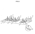
- charging equipment 3 (or charging station) is placed, which can charge a parking electric automobile or a hybrid vehicle (hereinafter, referred to vehicle 2).
- vehicle 2 is high speed charging equipment which supplies a high DC voltage such as DC 500V to the vehicle 2 for charging a battery 4 (see FIG. 1 ) of the vehicle 2 in a short time.
- the vehicle 2 corresponds to a device mounted with battery.
- the charging equipment 3 comprises a charge converter device 6 which converts an AC power voltage obtained from a system power supply 5 such as a commercial power source to a DC power voltage and outputs the converted voltage for charging, and a user operation unit 7 which is connected with the vehicle 2 by a user when charging.
- a parking mater 8 is also provided for measuring a parking time of a vehicle.
- the system power supply 5 corresponds to the system described hereinbefore.
- the charge converter device 6 comprises a plurality of power conversion units 9 which convert the AC power of the system power supply 5 into the DC current/voltage suitable for charging.
- the power conversion unit 9 converts the DC voltage of the system power supply 5 by a converter 10 into the DC voltage, and steps up the converted DC voltage to the AC voltage by an inverter 11. Then, the step-up AC voltage is converted to the DC voltage suitable for charging by a transformer 12 and a rectifier 13.
- each power conversion unit 9 is a small sized power source having, for example, a supply power of 10kW, a rated current of 25A, and a rated voltage of 400 to 500V.
- the charge converter device 6 includes a switching circuit 14 which changes a connecting combination (or connecting relationship) between the power conversion units 9 and the user operation units 7.
- the switching circuit 14 includes circuits each having a switch 17 at the place where a generating line 15 extending from each power conversion unit 9 intersects a generating line 16 extending from each user operation unit 7 (or charge terminal 18).
- a charge control unit 55 is constructed by the switching circuit 14.
- the user operation unit 7 comprises the charge terminal 18 arranged in the parking lot 1, a charge cable 19 extending from the charge terminal 18, and a power supply plug 20 attached at the end of the charge cable 19.
- the charge cable 19 has a power line 21 which is a transmission path of the electric power, and a signal line 22 which is a transmission path of various signals.
- CAN Controller Area Network
- the charge terminal 18 includes a terminal controller 23 which totally controls the charge terminal 18.
- the terminal controller 23 includes a charge execution processing unit 24 which manages the charge operation in the charge terminal 18.
- the charge execution processing unit 24 detects that the charge cable 19 is connected to the vehicle 2, the charge execution processing unit 24 supplies the DC power from the charge converter device 6 to the vehicle 2 through the power line 21, to charge the battery 4. Further, when full charging notice is inputted from the vehicle 2, the charge execution processing unit 24 transmits the full charging notice to the charge converter device 6, to stop the charging.
- the vehicle 2 has a plug insertion opening for quick charge 25 and a plug insertion opening for normal charge 26.
- the plug insertion opening for quick charge 25 is connected with the charge cable 19 of the charge terminal 18, to supply electric power such as DC 500V power through the charge cable 19.
- the plug insertion opening for normal charge 26 is connected with, for example, a home charge cable (not shown), to input AC power of AC 100V or 200V supplied from a home power supply into the vehicle 2.
- the AC power of the home power supply is converted to DC power by a charge circuit 27 in the vehicle 2, to supply the converted power to the battery 4.
- the vehicle 2 is equipped with a battery unit 28 which supplies electric power to a motor (not shown) as a vehicle drive source.
- the battery unit 28 is a so called battery pack.
- the battery unit 28 includes the battery 4 comprising a plurality of cells, and a battery control unit 29 which manages the charge operation at the side of the vehicle 2.
- a battery may be used comprising 100 cells with 3.6V placed side by side and having the rated voltage of 360V.
- the battery control unit 29 outputs necessary electric energy information Sa to the charge terminal 18 through the signal line 22 when starting the charging, so as to obtain a necessary electric energy for the charging.
- the necessary electric energy information Sa includes information on the necessary electric energy, for example, 20kW or 50kW corresponding to the free capacity of the battery 4.
- the battery control unit 29 always monitors the residual quantity of the battery during the charging. As a result of the monitoring, the battery control unit 29 outputs the charge amount information Sb to the charge terminal 18 through the signal line 22.
- the charge amount as mentioned above means the electric energy remaining in the battery 4 at that time.
- the terminal controller 23 comprises a battery information acquisition part 30 which acquires various signals from the vehicle 2 through the signal line 22, and a battery information transfer part 31 which outputs various information acquired by the battery information acquisition part 30 into the charge converter device 6.
- the terminal controller 23 acquires the various information outputted from the battery control unit 29 by the battery information acquisition part 30, and outputs the information into the charge converter device 6 by the battery information transfer part 31.
- the battery information acquisition part 30 and the battery information transfer part 31 construct a necessary electric energy acquisition means and a charge amount acquisition means.
- the charge converter device 6 includes a charge control device 32 which totally controls the charge converter device 6.
- the charge control device 32 allocates a power supply only to the power conversion unit 9 used for the charging among a plurality of power conversion units 9.
- the charge control device 32 is connected to each charge terminal 18 through a vehicle communication control part 33 equipped with the charge converter device 6.
- the charge control device 32 acquires the necessary electric energy information Sa and the charge amount information Sb from each charge terminal 18 through the vehicle communication control part 33.
- the vehicle communication control part 33 manages the communication between the charge converter device 6 and the plurality of charge terminals 18.
- the vehicle communication control part 33 constructs the necessary electric energy acquisition means and the charge amount acquisition means.
- the charge control device 32 comprises a charge operation control part 34 which sets the connecting combination between the power conversion unit 9 and the user operation unit 7 into the optimal pattern corresponding to the necessary electric energy.
- the charge operation control part 34 appropriately sets the connecting combination between the power conversion unit 9 and the user operation unit 7 (or charge terminal 18) by changing the connecting pattern of the switches 17 in the switching circuit 14. Further, the charge operation control part 34 dynamically changes the connecting combination between the power conversion unit 9 and the user operation unit 7 corresponding to various notice from the vehicle 2.
- the charge operation control part 34 constructs the charge control unit 55.
- the charge operation control part 34 grasps the necessary electric energy for charging the battery 4, that is, what kW of the electric energy is needed for the charging, based on the necessary electric energy information Sa acquired from the vehicle 2. Then, the charge operation control part 34 connects the needed number of the power conversion units 9 capable of supplying the necessary electric energy, with the user operation unit 7 by changing the switching state in the switching circuit 14, thereby to conduct the charging.
- the charge operation control part 34 successively acquires the charge amount information Sb from the vehicle 2 and dynamically changes the connecting combination between the power conversion unit 9 and the user operation unit 7 corresponding to the charge amount of the battery 4. That is, as shown in FIG. 4 , at the early stage of the charging, the power conversion unit 9 which can satisfy the request from the vehicle 2 is connected to the user operation unit 7, to conduct the constant current charging with a high charge current I. Then, when the charge amount is satisfied to some extent, the power conversion unit 9 is gradually cut off to gradually decrease the constant current, thereby to conduct the constant voltage charging.
- the charge control device 32 includes a fault detection part 35 which detects a fault of the power conversion unit 9.
- the fault detection part 35 detects that the output is "0" or decreased even though the power conversion unit 9 is operated, the fault detection part 35 decides that the power conversion unit 9 is out of order.
- the fault detection part 35 corresponds to a fault detection means.
- the charge control device 32 includes a separation part of unit 36 which separates the power conversion unit 9 with a fault from the use.
- the separation part of unit 36 separates the power conversion unit 9 with a fault from the available object, thereby to disconnect the power conversion unit 9 with a fault from the use of the charging equipment 3.
- the separation part of unit 36 corresponds to a separation means.
- the charging equipment 3 of the present embodiment has a manually setting function by which the charge pattern of the battery is manually set at the charge terminal 18.
- the reason why the manually setting function is provided with the charging equipment 3 is that a scrupulous service can be offered to each user corresponding to the user's situation by manually setting the charge mode.
- a situation includes a case that the user wants to charge the battery with at least a necessary charge amount when the user is in haste, or a case that the user wants to complete the charging until the user finishes business.
- the terminal controller 23 includes a charge appearance setting processing part 37 which works when the charge pattern is manually set.
- the charge terminal 18 includes an input part 38 comprising a ten key pad or a selection key pad, and a display 9 which displays various images or letters or the like.
- the input part 38 and the display 9 are used when a charge pattern is manually set at the charge terminal 18.
- the charge pattern includes detailed charge contents in which a charge time or a charge speed is used as a parameter.
- the charge appearance setting processing part 37, the input part 38, and the display 9 construct a charge pattern input means.
- the charge appearance setting processing part 37 When a charge pattern is inputted by the input part 38 or the display 9, the charge appearance setting processing part 37 outputs the charge pattern as manually setting input data Sc into the charge converter device 6.
- the charge operation control part 34 sets the allocation of the power conversion units 9 based on the manually setting input data Sc.
- a case is assumed in which a vehicle 2a is charged by a charge terminal 18a.
- a charge cable 19 of the charge terminal 18a is connected to the vehicle 2a
- a battery control unit 29 of the vehicle 2a outputs necessary electric energy information Sa corresponding to the residual quantity of a battery 4 into the charge terminal 18a. Accordingly, when the charge amount is largely lowered, this information is notified to the charge terminal 18a.
- a battery information acquisition part 30 receives the necessary electric energy information Sa
- the charge terminal 18a outputs the necessary electric energy information Sa through a battery information transfer part 31 into the charge operation control part 34.
- the charge operation control part 34 changes a switching state of the switching circuit 14 based on the necessary electric energy information Sa, and connects a first power conversion unit 9a to a fifth power conversion unit 9e all of which are in the available state, with the charge terminal 18a.
- a vehicle 2b is connected to the charge terminal 18b while the vehicle 2a is being charged.
- a battery control unit 29 of the vehicle 2b also outputs necessary electric energy information Sa into the charge terminal 18b, and the charge terminal 18b transfers the necessary electric energy information Sa to the charge operation control part 34.
- the charge operation control part 34 receives the necessary electric energy information Sa from the vehicle 2b, the charge operation control part 34 connects the available power conversion units 9 at that time, that is, a sixth power conversion unit 9f to tenth power conversion unit 9j, with the charge terminal 18b.
- the charge operation is started by the constant current charging. Then, when the charge amount reaches the predetermined amount, the charge current I is decreased at that time and the charge operation is changed to be conducted by the constant voltage charging.
- the unnecessary power conversion units 9 at that time are disconnected one after another from the use. That is, as the charge operation proceeds, the power conversion units 9 are disconnected in the order of 9e ⁇ 9d ⁇ 9c ⁇ 9b ⁇ 9a from the use.
- the same charge operation is conducted at the charge terminal 18b.
- the charge operation control part 34 connects the five power conversion units 9 such as the second power conversion unit 9b to the fifth power conversion unit 9e and the tenth power conversion unit 9j, with the charge terminal 18c, so as to charge the vehicle 2c by using the five added powers.
- the charge operation control part 34 charges the vehicle 2d by using only the available power conversion units 9 when starting the charging.
- the battery 4 of the vehicle 2d is charged by the first power conversion unit 9a, the eighth power conversion unit 9h and the ninth power conversion unit 9i. Note that in this case a longer charge time is needed than the case in which five power conversion units 9 are used.
- a battery control unit 29 of the vehicle 2e outputs the necessary electric energy information Sa notifying that the charge amount of the battery 4 is not so decreased, into the charge terminal 18a.
- the charge operation control part 34 connects the available power conversion units 9 at that time, for example, the two power conversion units 9 including the second power conversion unit 9b and the third power conversion unit 9c, with the charge terminal 18a, so as to charge the battery 4 of the vehicle 2e.
- the charge operation control part 34 of the present embodiment can dynamically change the connecting combination of the power conversion units 9 by using the available power conversion units 9 at that time. For example, when two vehicles 2 are simultaneously being charged, if one power conversion unit 9 completes the charging, this available power conversion unit 9 can be allocated to the other charging. This allows the available power conversion unit 9 to be used efficiently, resulting in the more improvement of the charge efficiency.
- the manually setting charge pattern includes a charge schedule comprising a request for the charge time such as 10 min or 20 min, a request for stopping the charge when the charge amount of the battery 4 is in 80% or more in 10 min, a request for completing the full charging in 60 min, and a request for completing the full charging by the requested time or the like.
- the charge appearance setting processing part 37 outputs the charge schedule as manually setting input date Sc into the charge operation control part 34 through the vehicle communication control part 33.
- the charge operation control part 34 executes the charging associated with the charge schedule.
- the allocation of the power conversion units 9 can be dynamically changed, allowing a new charge schedule to be performed associated with a request from a user.
- the manually setting of the charge pattern includes a request item forcedly intruding a charge operation into the charge schedule.
- the charge appearance setting processing part 37 detects the intruding request operation at the charge terminal 18, the charge appearance setting processing part 37 outputs the charge intruding request as manually setting input data Sc, into the charge operation control part 34.
- the charge operation control part 34 temporally allocates one power supply of the vehicle 2 having a sufficient time for the charging to the other vehicle 2 for the charging thereof, so as to complete to charge the other vehicle 2 in time.
- a plurality of small power conversion units 9 are provided with the charge converter device 6, and these power conversion units 9 are allocated to the respective user operation units 7 in use, to supply power sources for charging to the respective charge terminals 18.
- a single charge converter device 6 can simultaneously charge a plurality of vehicles 2 because the plurality of charge terminals 18 are available for charging. This allows another waiting vehicle 2 to be charged without waiting the completion of charging the vehicles which are being charged.
- the fault detection part 35 successively monitors if there is a fault in the power conversion units 9. Then, when the fault detection part 35 detects a fault in a power conversion unit 9, the fault detection part 35 notifies which number of the power conversion unit 9 is with a fault into the unit separation part 36. When the number of the power conversion unit 9 is inputted, the unit separation part 36 disconnects the power conversion unit 9 having the number from the use, and excludes the power conversion unit 9 with a fault from the allocation object in the allocation of power supplies hereinafter. Accordingly, the power conversion unit 9 with a fault is not used as a power supply, allowing a normal charge to be conducted.
- the present embodiment is not limited to the above mentioned construction, and can be modified as mentioned below.
- the charge converter device 6 may comprise a host communication control part 51 and the host communication control part 51 may transmit various information on the charge operation into a server through the network. In such a case, it is possible to collect the using status information from the charge converter device 6 arranged in various locations, resulting in the more improvement of the services.
- the charge converter device 6 may be equipped with a rechargeable battery 52 for using the rechargeable battery 52 as a power supply of a power conversion unit 9.
- the rechargeable battery 52 may be charged at night with a lower electricity rate, and the rechargeable battery 52 may be used as a power supply in the daytime by turning on a switch 53 arranged on the pathway to the rechargeable battery 52. Further, the rechargeable battery 52 may be used as an emergency power supply at the time of power cut.
- a control method of controlling the charge current I conducted by the constant current charging following by the constant voltage charging is not limited to the method of gradually decreasing the charge current I by decreasing the number of the power conversion units 9 in use.
- the available power conversion unit 9 may be allocated to the charging operation with the insufficient number of the power conversion units 9 as a power supply.
- the charge terminal 18 may be provided with an electricity leakage detecting function and an opening and closing function. Accordingly, when a leakage of electricity is detected at the charge terminal 18, the charge terminal 18 may be disconnected from the power supply by using the opening and closing function.
- one of the power conversion units 9 almost completing the charging operation may be forcedly used as a power supply for newly charging the vehicle 2.
- the device mounted with battery is not limited to a vehicle 2 such as an electric automobile and a hybrid vehicle.
- the device mounted with battery may be an automatic transporter, a fork lift, a robot, a visitor cart, a motorcycle or a bus.
- the manually setting function is provided for manually setting the charge pattern of the battery 4 at the charge terminal 18.
- the charge operation is conducted following the set charge pattern.
- a function of the timer charge is more specifically realized, by which the charge operation is conducted to satisfy the charge schedule defining the charge end time of the battery 4 equipped with a vehicle 102 as a device mounted with battery.
- a function of the quick charge is more specifically realized, by which the charge operation is conducted to satisfy the quick charge request requesting to immediately charge the battery 4 with the predetermined charge output capacity.
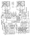
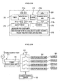
- FIG. 8 is a block diagram showing the charging equipment of the second embodiment of the present invention.
- charging equipment 103 of the second embodiment further comprises the construction for realizing both functions of the timer charge and the quick charge in comparison to the charging equipment 3 (see FIG. 1 ) of the first embodiment.
- a charge control device 132 in a charge converter device 106 of the charging equipment 103 comprises a charge application processing part 40, a timer charge processing part 41, a quick charge processing part 42, a timer charge management database (hereinafter, referred to "DB") 45, a quick charge management DB 46, a power conversion unit DB 47, an operation time DB 48, a CPU 60, and a memory 61, in addition to the charge operation control part 34, the fault detection part 35, and the unit separation part 36.
- the charge control device 132 and the switching circuit 14 construct a charge control unit 155.
- the processing parts 40 to 42, the DBs 45 to 48, the CPU 60 and the memory 61 are additionally included.
- One of the needs is related to the time, for example, by when the charge operation should be completed.
- the other need is, for example, a demand for immediately conducting the charge operation with the predetermined charge output capacity.
- the charge application processing part 40 performs a process of the charge application.
- the timer charge processing part 41 performs an allocation process of the power conversion units 9 for the timer charge.
- the quick charge processing part 42 performs an allocation process of the power conversion units 9 for the quick charge.
- the functions of the processing parts 40 to 42 are performed by the CPU 60 of executing a predetermined program stored in the memory 61.
- the timer charge management DB 45 is a database for managing the timer charge.
- the quick charge management DB 46 is a database for managing the quick charge.
- the power conversion unit DB 47 is a database for managing the allocation of the power conversion units 9 used for charging.
- the operation time DB 48 is a database for managing the accumulation operation time of the power conversion unit 9.
- the charge converter device 106 in the second embodiment comprises a power output part 110 including a plurality of power conversion units 9 which convert the AC power of the system power supply 5 into the DC current/voltage suitable for charging.
- the charge terminal 118 in the second embodiment comprises an acceptance and display part (or display) 65 and a storage part 66 instead of the display 39 in the first embodiment (see FIG. 1 ).
- the acceptance and display part 65 is, for example, a touch panel for inputting or displaying various information.
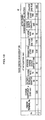
- FIG. 9 is a diagram showing a data structure of the timer charge management DB.
- the timer charge management DB 45 stores a charge coefficient ⁇ , a residual quantity (or battery residual quantity) when the charge of the battery 4 in the vehicle 102 is applied, a charge rate (%) when the charging is ended specified at the charge application time, a connection starting time, a charge end time specified at the charge application time, a charge rate (%) when the charging is ended scheduled after the power conversion unit allocation, a charge start time and a charge end time scheduled after the power conversion unit allocation, a charge output capacity (kW), and an RT flag, at each charge terminal 18.
- each of the plurality of charge terminals 18 has the consecutive number, for example, referred to the charge terminals No.1 to No.4.
- the charge coefficient ⁇ is a coefficient indicating the increase of the charge rate when the battery 4 is charged by the unit time charging with the unit charge output capacity.
- the coefficient is calculated the following equation.
- the vehicle 102 comprises a storage part for storing the charge coefficient ⁇ . That is, a battery unit 128 of the vehicle 102 in the second embodiment comprises a charge coefficient storage part 62 storing the charge coefficient ⁇ of the battery 4 equipped with the vehicle 102 (see FIG. 8 ).
- the charge coefficient ⁇ may be calculated by acquiring information (or value) including a model number of the battery 4, by which the charge coefficient ⁇ can be calculated, thereby to calculate the charge coefficient ⁇ based on the information. Further, another method can be used in which a performance of the battery 4 in the vehicle 102 is regularly measured. Then, the information by which the charge coefficient ⁇ can be calculated may be updated based on the measured result. This allows the charge schedule to be achieved more accurately.
- FIG. 10 is a diagram showing a data structure of the quick charge management DB.
- the quick charge management DB 46 stores a charge terminal number, a charge coefficient ⁇ , a battery residual quantity (%) at the charge application time, a charge rate (%) when the charging is completed specified at the charge application time, a specified charge output capacity (kW) at the charge application time, a charge start time and a charge end time specified at the charge application time, a charge rate (%) when the charging is completed scheduled after the power conversion unit allocation, a charge output capacity (kW) scheduled after the power conversion unit allocation, and a charge start time and a charge end time scheduled after the power conversion unit allocation.
- the charge coefficient ⁇ is used for the same purpose as explained in FIG. 9 and is calculated in the same equation described hereinbefore.
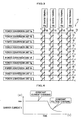
- FIG. 11 is a diagram showing a data structure of the power conversion unit DB.
- the power conversion unit DB 47 stores the number of the charge terminal to which the power is supplied; the number being set (or stored) with a predetermined time unit (in this case, 5 min unit) for each of the plurality of power conversion units 9. Further, in the case of the quick charge, the power conversion unit DB 47 stores the number of the charge terminal to which the power is supplied; the number being set (or stored) by adding "S" at the beginning of the number.
- a sequential alphabetical letter is added to each of the plurality of power conversion units 9, for example, referred to the power conversion units A to E.
- the following method may be used. That is, the information on the time zone of the peak electric power (or time zone with peak electricity consumption) is acquired from a server computer (not shown) arranged outside the charging equipment 3 through the host communication control part 51. Then, the predetermined number of the power conversion units 9 are selected in the order of longer operation time among the plurality of power conversion units 9 indicated by the operation time DB 48 (for example, the power conversion unit 9 with the longest operation time). Then, the operation of the selected power conversion units 9 is restricted during the time zone of the peak electric power. By using the above mentioned method, it is possible to add a function for restricting the maximum power quantity only during the time zone of the peak electric power.
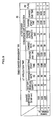
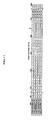
- FIG. 12 is a diagram showing a data structure of the operation time DB.
- the operation time DB 48 stores an accumulation operation time for each of the plurality power conversion units 9 (A to E).
- the accumulation operation time described in FIG. 12 is shown as the time per one year. However, it is possible to optionally decide what time unit may be used to accumulate the operation time. By using the operation time DB 48, it is possible to level the use of the plurality of power conversion units 9.
- FIGS. 13A to 13D are diagrams each showing an example of the charging operation conducted by the charging equipment of the second embodiment.
- FIG. 13A shows vehicles to be charged and the charge operation contents thereof.
- FIG. 13B is a diagram showing the state that the vehicles to be charged are connected to the charging equipment.
- FIG. 13C shows the allocation result of the power conversion units when three vehicles are sequentially connected to the charging equipment.
- FIG. 13D shows the allocation result of the power conversion units when another vehicle is additionally connected to the charging equipment following the first three vehicles.
- the sequential number of reference is added to each of the vehicles 102 as a plurality of devices mounted with battery, that is, referred to the vehicles EV1 to EV4.
- the charge output capacity (or supplied power) of the respective power conversion units A to E is 10kW, which is the same capacity as in the first embodiment.
- the vehicles EV1 to EV4 are vehicles which can be charged so that each charge rate is increased from 0% to 80% by charging each vehicle with the power of 20kW for 80 min. In such a case, the following equation is obtained.
- FIGS. 13A to 13D show that the plurality of vehicles EV1 to EV4 are sequentially connected to the charge terminal No.1 to No.4, and the respective charge patterns (timer charge or quick charge) are set at the charge terminal No.1 to No.4. Further, these FIGS show how the use (or allocation) of the power conversion units is changed before / after the vehicle EV4 is added.
- the timer charge function provided with the charge converter device 106 allows the function for improving the convenience to be realized, including the function of intruding quick charging, or completing the charging within the specified charge end time.
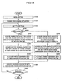
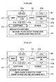
- FIG. 14 is a flowchart showing a total procedure for conducting the charge processing which realizes both charge modes of the timer charge and the quick charge in the second embodiment.
- the charge application processing unit 40 starts the operation before the operation start time (or business start time) of the charging equipment 103.
- the charge application processing unit 40 may start at the predetermined time, or at the time when the operation manager turns on the main switch (not shown).
- the charge application processing unit 40 performs the initial setting (Step 1010). That is, the charge application processing unit 40 sets the timer setting feasible time (or charge end time capable of being specified), and initializes the power conversion unit DB 47 (that is, setting the initial value of "0") .
- the timer setting feasible time may be, for example, a business end time.
- the charge application processing unit 40 receives the information on the initial charge application from the charge terminal 118 (Step 1012).
- the charge application is conducted at the charge terminal 118 by the following procedure.
- the charge appearance setting processing part 37 of the charge terminal 118 displays a charge reservation / message screen (or acceptance screen) 201 on the acceptance and display part 65, as shown in FIG. 20 .
- FIG. 20 is a diagram showing a charge reservation / message screen waiting a charge reservation.
- the charge reservation / message screen 201 comprises a timer charge acceptance part 211 which accepts the charge schedule specifying the charge end time of the battery 4, a quick charge acceptance part 212 which accepts the quick charge request requesting to immediately execute the charge operation with a predetermined charge output capacity of the battery 4, a charge target acceptance part 213 which accepts a value of the charge rate of the battery 4, an acceptance button 214 which accepts a charge application, a decision button 215 which decides the specified charge pattern, and a message displaying area 216 which displays a message to the user.
- the timer charge acceptance part 211 comprises a plurality of specifying buttons 211a for specifying the charge end time.
- the charge target acceptance part 213 comprises a plurality of specifying buttons 213a for specifying the value of the charge rate. Then, when the acceptance button 214 is pushed, the charge appearance setting processing part 37 transmits the information that the charge application was accepted into the charge converter device 106.
- the charge application processing unit 40 when the charge application processing unit 40 receives the information that the initial charge application was accepted, the charge application processing unit 40 sets the initial value of "0" in the RT flag of the timer charge management DB 45.
- the charge application processing unit 40 determines whether the charge mode selected by the user for the vehicle 102 to be connected with one of the plurality of charge terminals 118 (for example, charge terminal No. 1 to No. 4), is a timer charge or a quick charge.
- the selection of the charge mode is conducted at the charge terminal 118 as follows. That is, the charge appearance setting processing part 37 displays a charge reservation/message screen 202 on the acceptance and display part 65 as shown in FIG. 21 .
- FIG. 21 shows a charge reservation/message screen when the timer charge was selected.
- the charge appearance setting processing part 37 displays a message in the message display area 216 for requesting the user to specify the charge end time and the charge rate.
- a default charge end time and a default charge rate are displayed on the initial screen.
- the charge appearance setting processing part 37 stores the accepted information in the storage part 66. Then, the charge appearance setting processing part 37 displays a charge reservation/massage screen 203 shown in FIG.
- FIG. 22 shows a charge reservation/message screen when the charge schedule and the charge rate were specified in the timer charge.
- an upper value of the charge rate capable of being set exists, for example, 80%, it is possible to optionally change the upper value of the charge rate by improving the performance of the battery 4.
- FIG. 23 shows a charge reservation/message screen when the quick charge was selected.
- the charge appearance setting processing part 37 displays a message in the message display area 216 for requesting the user to specify the charge rate.
- a default charge rate is displayed on the initial screen.
- the charge appearance setting processing part 37 stores the accepted information in the storage part 66.
- the charge appearance setting processing part 37 displays a charge reservation/massage screen 205 shown in FIG. 24 , and transmits the accepted information stored in the storage part 66 into the charge converter device 106.
- the accepted information is transmitted as manually setting input data Sc (see FIG. 8 ) on the charge pattern information including the charge mode.
- FIG. 24 shows a charge reservation/message screen when the charge rate was specified in the quick charge.
- step 1020 of FIG.14 when the charge application processing part 40 determines that the selected charge mode is a timer charge based on the received manually setting input data Sc ("timer" in step 1020), the charge application processing part 40 advances the process to the step 1030. In contrast, when the charge application processing part 40 determines that the selected charge mode is a quick charge based on the received manually setting input data Sc ("quick" in step 1020, the charge application processing part 40 advances the process to the step 2010.
- the timer charge processing part 41 acquires the data on the connecting start time, the charge end time, and the charge rate from the manually setting input data Sc received from the charge terminal 118, thereby to set the data into the columns of the charge terminal 118 in the area of the timer charge management DB at the application time (see FIG. 9 ) (Step 1030).
- the connecting start time is a time when the user connects the vehicle 102 with the charge terminal 118 and pushes the decision button 215 on the charge reservation/message screen 203 (see FIG. 22 ) displayed on the acceptance and display part 66 of the charge terminal 118.
- the timer charge processing part 41 acquires the battery residual quantity (%) of the battery 4 in the vehicle 102, by communicating with the vehicle 102 through the charge terminal 118, thereby to set the data into the corresponding columns in the area of the timer charge management DB at the application time, related to the charge terminal 118 (Step 1040).
- the battery residual quantity (%) can be calculated by the necessary electric energy information Sa (see FIG. 8 ) before starting the charging.
- the necessary electric energy information Sa in the second embodiment includes the data of (1) an upper limit value of the charge voltage, (2) a battery total capacity, (3) a specified current value (initial), (4) a battery residual capacity, and (5) an upper value of the charge current.
- the above mentioned data are provided by adding the data of (5) an upper value of the charge current to the necessary electric energy information Sa in the first embodiment. More specifically, the battery residual quantity (%) is calculated by the following equation.
- the timer charge processing part 41 allocates the power conversion units when the timer charge is applied (Step 1050).
- the charge terminal No. is set to each of the plurality of power conversion units 9 (A to E) in the power conversion unit DB 47 (see FIG. 11 ).
- the step 1050 will be explained in detail hereinafter (see FIG. 15 ).
- the quick charge processing part 42 acquires the charge rate data from the manually setting input data Sc received from the charge terminal 118, thereby to set the charge rate in the area of the quick charge management DB at the application time (see FIG. 10 ) with adding the charge terminal No. (Step 2010).
- the quick charge processing part 42 acquires the battery residual quantity (%) and the specified charge output capacity (kW) on the battery 4 in the vehicle 102, by communicating with the vehicle 102 through the charge terminal 118, thereby to set the above mentioned data in the area of the quick charge management DB 46 at the application time (Step 2020).
- the specified charge output capacity (kW) is a charge output capacity (or supplied power) specified corresponding to the available capacity of the battery 4 as the electric power needed for the quick charge.
- the specified charge output capacity is calculated by the necessary electric energy information Sa (see FIG. 8 ).
- the quick charge processing part 42 allocates the power conversion units at the time of the quick charge application (Step 2030).
- the charge terminal No. is set to each of the plurality of power conversion units 9 (A to E) in the power conversion unit DB 47 (see FIG. 11 ) .
- the step 2030 will be explained in detail hereinafter (see FIG. 17 ).
- the charge operation control part 34 in the charge control device 132 determines the upper limit value of the charge output capacity (or supplied power) by communicating with the vehicle 102 before starting the charging, then executes the charging associated with the contents in the power conversion unit DB 47 (Step 1060).
- the charge operation control part 34 temporally stops the charging, and restarts the charging after determining the upper limit value of the charge output capacity by communicating again with the vehicle 102.
- the charge operation control part 34 may grasp the number of the power conversion units capable of being disconnected and input the data into the power conversion unit DB 47 (see FIG.11 ). As shown in FIGS.13A to 13D , the charge operation control part 34 secures the five power conversion units (A to E) for 30 min to charge the vehicle EV4. However, if the necessary charge amount is supplied by the number of the power conversion units used for four vehicles for the last 10 min, the charge operation control part 34 may separate the power conversion unit A with the longest operation time referring to the operation time DB 48 (see FIG.12 ) (that is, may exclude the unit A from the use), thereby to reflect the result in the power conversion unit DB 47.
- the charge application processing unit 40 decides whether a next charge application is received or not.
- the next charge application may be, for example, a charge application through other charge terminal 118.
- the charge application processing unit 40 returns the process to the step 1015.
- the charge application processing unit 40 goes in a standby state waiting the next charge application. Accordingly, the process in FIG.14 terminates when business is over or when a main switch (not shown) is turned off or the like.
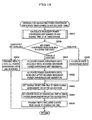
- Step 1050 the allocation process of the power conversion units when the timer charge is applied (Step 1050) will be explained in detail.
- the timer charge processing unit 41 calculates the number of the necessary power conversion units PN and the charge time CT in the timer charge (Step 3010). That is, the timer charge processing unit 41 acquires a charge coefficient ⁇ from the vehicle 102 through the charge terminal 118, and sets the value in the timer charge management DB 45. Then, using the charge coefficient ⁇ , the timer charge processing unit 41 calculates the number of the necessary power conversion units PN, which is the number of the units 9 capable of completing the charge for achieving the charge rate specified by a user at the specified charge time zone from the connecting start time to the charge end time specified by the user.
- the timer charge processing unit 41 calculates the charge time CT needed in the charge processing when the charge processing is conducted by using the number PN power conversion units 9.
- the timer charge processing unit 41 stores the values of the number PN of the necessary power conversion units 9 and the charge time CT in the memory 61.
- the step 3010 will be explained in detail hereinafter (see FIG.16 ).
- the timer charge processing unit 41 decides whether the number PN power conversion units 9 are available or not (that is, units 9 without allocated) at the time zone from the connecting start time to the time when the charge time CT is added to the connecting start time. Then, if the power conversion units 9 are "completely not available", the timer charge processing unit 41 advances the process to the step 3045. If the power conversion units 9 are "partially available", the timer charge processing unit 41 advances the process to the step 3030. Further, if the power conversion units 9 are "available”, the timer charge processing unit 41 advances the process to the step 3040.
- Step 3020 if the power conversion units 9 are decided as “partially available” (Step 3020: “partially available”), the timer charge processing unit 41 firstly allocates the power conversion units 9 available by the time when the number PN conversion units needed can be secured (Step 3030). That is, the timer charge processing unit 41 selects the available power conversion units 9. Then, the timer charge processing unit 41 sets the charge terminal No. as a power supply target to the respective selected power conversion units 9 by the time when the number PN or more power conversion units 9 can be secured from the connecting start time, in the power conversion unit DB 47 (see FIG.11 ).
- the timer charge processing unit 41 allocates the power conversion units after the number PN power conversion units 9 are secured (Step 3035). That is, the timer charge processing unit 41 recalculates the number PN of the necessary power conversion units to achieve the charge rate specified by the user at the time zone form the time when the number PN or more power conversion units 9 can be secured to the charge end time specified by the user. Further, the timer charge processing unit 41 selects the PN number power conversion units 9 after the recalculation in the order so that the power conversion unit 9 with less operation time in the operation time DB is selected among the secured power conversion units 9. Further, the timer charge processing unit 41 sets the charge terminal No.
- the timer charge processing unit 41 sets the charge terminal No. as a power supply target by the charge end time specified at the charge application time, in the power conversion unit DB 47 (see FIG.11 ).
- the timer charge processing unit 41 may allocate the power conversion units 9 so as to conduct the charge operation after waiting the time when the number PN or more power conversion units 9 can be secured, instead of performing the processes in the steps 3030 and 3035.
- the timer charge processing unit 41 recalculates the number PN of the necessary power conversion units at the time zone from the time when the number PN or more power conversion units 9 can be secured to the charge end time.
- the timer charge processing unit 41 selects the PN number power conversion units 9 after the recalculation in the order so that the power conversion unit 9 with less operation time in the operation time DB is selected among the secured power conversion units 9. Further, the timer charge processing unit 41 sets the charge terminal No.
- Step 3020 if the power conversion units 9 are decided as “available” (Step 3020: “available”), the timer charge processing unit 41 allocate the power conversion units 9 (Step 3040). That is, the timer charge processing unit 41 selects the number PN power conversion units 9 available in the order of the less operation time thereof in the operation time DB 48. Then, the timer charge processing unit 41 sets the charge terminal No. as a power supply to the selected respective conversion units 9 from the connecting start time to the time when the charge time CT is added to the connecting start time, in the power conversion unit DB 47 (see FIG.11 ).
- Step 3020 the timer charge processing unit 41 transmits a reply (or related information) notifying that all the power conversion units 9 are fully reserved by the charge end time specified by the user, into the charge terminal 118 through the vehicle communication control part 33 (Step 3045).
- the charge appearance setting processing part 37 of the charge terminal 118 receives the above mentioned reply and stores it in the storage part 66 (see FIG.8 ). Then, the charge appearance setting processing part 37 displays a charge reservation/message screen 206 on the acceptance and display part 65 as shown in FIG.25.
- FIG. 25 shows a charge reservation/message screen when receiving a reply notifying that the charge reservation is fully booked in the timer charge. That is, the charge appearance setting processing part 37 displays a massage that the charge reservation is fully booked by the specified charge end time in the message display area 216.
- the timer charge processing part 41 sets the charge start time and the charge end time, which are indicated by setting the charge terminal 118 No. as a power supply to the respective power conversion units (A to E) in the power conversion unit DB 47, into the area of the timer charge management DB 45 after the power conversion unit 9 allocation (Step 3050).
- the timer charge processing part 41 calculates how many percents of the charge are completed at the charge end time, thereby to set the charge rate at the charge end time in the area of the timer charge management DB 45 after the power conversion unit allocation (step 3060).
- the timer charge processing part 41 transmits a reply (or related information) including a charge rate value at the charge end time in the area of the timer charge management DB 45 after the power conversion unit allocation, into the charge terminal 118 through the vehicle communication control part 33 (Step 3070).
- the charge appearance setting processing part 37 of the charge terminal 118 receives the reply and stores it in the storage part 66 (see FIG.8 ). Then, based on the reply stored in the storage part 66, the charge appearance setting processing part 37 displays a charge reservation/message screen 207 shown in FIG. 26 on the acceptance and display part 65.
- FIG. 26 shows a charge reservation/message screen when receiving a reply including the charge rate value at the charge end time in the timer charge. That is, the charge appearance setting processing part 37 displays the massage including the charge rate value at the charge end time in the message display area 216.
- the reply may include a scheduled charge end time as shown in FIG. 26 .
- Step 3010 the calculation process of the necessary power conversion unit number PN and the charge time CT in the timer charge (Step 3010) will be explained referring to FIG.16 .
- the timer charge processing part 41 acquires a charge coefficient ⁇ by communicating with the vehicle 102 through the charge terminal 118, thereby to set the data in the timer charge management DB 45 (Step 6010).
- the timer charge processing part 41 calculates the specified charge time T which is the time from the connecting start time to the charge end time specified by a user referring to the timer charge management DB 45 (Step 6020).
- the timer charge processing part 41 calculates the requested increasing charge rate ⁇ (Step 6030).
- the timer charge processing part 41 calculates the necessary charge output capacity P which is the supply power needed for completing the charge to achieve the charge rate specified by the user in the specified charge time zone, by using the charge coefficient ⁇ (Step 6040).
- Step 6050 the timer charge processing part 41 determines whether the following relationship is satisfied or not (Step 6060): Necessary charge output capacity P / (Charge output capacity (or supply power) per single charge converter unit x N) ⁇ 1.
- the necessary power conversion unit number PN is stored in the memory 61.
- the timer charge processing part 41 sets the charge output capacity (kW) as the total power supplied from the PN power conversion units 9, in the area of the timer charge management DB 45 after the power conversion unit allocation.
- the timer charge processing part 41 calculates the charge time CT if PN power conversion units are used (Step 6090).
- Step 2030 the allocation process of the power conversion units when the quick charge is applied.
- the quick charge processing part 42 acquires a charge coefficient ⁇ by communicating with the vehicle 102 through the charge terminal 118, and sets the value in the quick charge management DB 46 (Step 4010).
- the quick charge processing part 42 calculates the charge time QT in the quick charge by using the charge coefficient ⁇ , thereby to set the quick charge end time in the area of the quick charge management DB 46 at the application time (Step 4020) .
- step 4020 will be explained in detail, referring to FIG. 18 .
- the quick charge processing part 42 calculates the requested increasing charge rate ⁇ (Step 7010).
- the value of the increasing charge rate ⁇ is stored in the memory 61.
- the quick charge processing part 42 stores the value of the specified charge output capacity (kW) shown in the area of the quick charge management DB 46 at the application time as a charge output capacity P, in the memory 61 (Step 7020).
- the quick charge processing part 42 calculates a charge time QT (Step 7030).
- the quick charge processing part 42 stores the present time as a charge starting time ST in the memory 61, and sets the value of the charge starting time ST into the column of the charge starting time in the area of the quick charge management DB 46 at the application time (Step 7040).
- the quick charge processing part 42 calculates a charge end time ET (Step 7050).
- the quick charge processing part 42 sets the value of the charge end time ET into the column of the charge end time positioned in the area of the quick charge management DB 46 at the application time (Step 7060).
- the quick charge processing part 42 determines whether a charge reservation is booked or not at the target time zone from the charge starting time ST to the charge end time ET. That is, the quick charge processing part 42 determines whether the value except for the initial value "0" is inputted or not in the target time zone, referring to the power conversion unit DB 47 (see FUG.11). If the charge reservation is booked in the target time zone (Step 4030; Yes), the quick charge processing part 42 advances the process to the step 4040, while when no charge reservation is booked in the target time zone (Step 4030; No), the quick charge processing part 42 advances the process to the step 4070.
- the quick charge processing part 42 copies the data in the area of the quick charge management DB 46 at the application time and sets the data into the corresponding columns in the area after the power conversion unit allocation. Then, the quick charge processing part 42 advances the process to the step 4100.
- the quick charge processing part 42 specifies the charge terminal 118 occupying the power conversion units 9 in the target time zone referring to the power conversion unit DB 47 (that is, by the charge terminal No.). Then, the quick charge processing part 42 determines whether the using time of the power conversion unit 9 connected with the specified charge terminal 118 can be shifted to other time zone or not, referring to the timer charge management DB 45 (see FIG.9 ).
- the quick charge processing part 42 decides that it is not possible to shift each using time of all power conversion units 9 (Step 4040; No)
- the quick charge processing part 42 advances the process to the step 4050.
- the quick charge processing part 42 decides that it is possible to shift each using time of all or a part of the power conversion units 9 (Step 4040; Yes)
- the quick charge processing part 42 advances the process to the step 4060.
- the quick charge processing part 42 transmits a reply recommending the timer charge (or related information) into the charge terminal 118 through the vehicle communication control part 33.
- the charge appearance setting processing part 37 of the charge terminal 118 receives the above mentioned reply and stores it in the storage part 66 (see FIG.8 ). Then, the charge appearance setting processing part 37 displays a charge reservation /message screen 208 shown in FIG. 27 on the acceptance and display part 65 based on the reply stored in the storage part 66.
- FIG.27 shows a charge reservation /message screen when receiving a reply recommending the timer charge. That is, the charge appearance setting processing part 37 displays a message recommending the timer charge in the message display area 216.
- the quick charge processing part 42 performs a shift process of the using time of the power conversion unit.
- the charge terminal No. is reset in the power conversion unit DB 47 (see FIG.11 ).
- step 4060 will be explained in detail, referring to FIG.19 .
- the quick charge processing part 42 selects the charge terminal 118, which can be a target for shifting the using time thereof, and sets "1" in the corresponding RT flag of the timer charge management DB 45, referring to the power conversion unit DB 47 (see FIG. 11 ) and the timer charge management DB 45 (see FIG.9 ) (Step 8010). More specifically, referring to the charge end time in the timer charge management DB 45 (at the application time) and the time zone in which the corresponding charge terminal No. in the power conversion unit DB 47 is set, if there is a difference in the time more than the predetermined time (for example, about 15 min), "1" is set in the RT flag. This allows the charge terminal 118 to be selected having the available time more than the predetermined time, even if the using time of the power conversion unit is shifted.
- the predetermined time for example, about 15 min
- the quick charge processing part 42 selects the charge terminal 118 of which charge end time is most apart from the present time among the charge terminals 118 with the RT flag of "1" in the timer charge management DB 45 (see FIG. 9 ) (Step 8020).
- the charge end time is the time indicated in the power conversion unit DB 47 (see FIG.11 ).
- the quick charge processing part 42 determines whether the timer charge at the selected target charge terminal 118 is completed or not by the specified charge end time requested by the user, even by restarting the timer charge from the charge end time (14:00 in FIG.10 ) listed in the area of the quick charge management DB 46 (see FIG. 10 ) at the application time, referring to the timer charge management DB 45. If the quick charge processing part 42 decides that the charge at the target charge terminal 118 is completed as requested (Step 8030; Yes), the quick charge processing part 42 advances the process to the step 8040. In contrast, if the quick charge processing part 42 decides that the charge at the target charge terminal 118 is not completed as requested (Step 8030; No), the quick charge processing part 42 advances the process to the step 8050.
- the quick charge processing part 42 shifts the using time of the target charge terminal 118 from the present time to the quick charge end time. That is, the quick charge processing part 42 shifts the using time of the power conversion unit 9, by shifting the setting position of the charge terminal No. in the power conversion unit DB 47 so that the charge rate when the timer charge is applied is satisfied for the target charge terminal 118. Then, the quick charge processing part 42 sets the charge start / end time after the shift process of the using time into the area of the timer charge management DB 45 (see FIG.9 ) after the allocation of the power charge units, for the target charge terminal 118.
- the quick charge processing part 42 shifts the using time for the target charge terminal 118 in the range for satisfying the request at the application time. That is, the quick charge processing part 42 shifts the using time of the power conversion unit 9, by shifting the setting position of the charge terminal No. in the power conversion unit DB 47, within the range for satisfying the charge end time and the charge rate when the timer charge is applied, for the target charge terminal 118. In such a case, the charge end time when the timer charge is applied becomes the charge end time after the allocation of the power conversion unit.
- the quick charge processing part 42 sets the charge start / end time after the shift process of the using time into the area of the timer charge management DB 45 (see FIG.9 ) after the allocation of the power conversion units, for the target charge terminal 118.
- the necessary power conversion unit number PN may be recalculated so as to achieve the charge rate specified by the user. This allows the reallocation of the power conversion units, which results in the increase of the probability of the case that the using time can be shifted from the present time to the quick charge end time.
- the quick charge processing part 42 determines whether the number of the power conversion units capable of satisfying the specified charge output capacity needed at the quick charge start time is secured or not. Here, the decision is made considering the power conversion units 9 which are not scheduled to be used (for example, charge conversion unit E in FIGS. 13C to 13D ). If the quick charge processing part 42 decides that the necessary number of the power conversion units is secured (Step 8060; Yes), the quick charge processing part 42 advances the process to the step 4080 (see FIG. 17 ) , while the quick charge processing part 42 decides that the necessary number of the power conversion units is not secured (Step 8060; No), the quick charge processing part 42 advances the process to the step 8070.
- the quick charge processing part 42 selects a charge terminal 118 of which charge end time is secondly apart from the present time among the charge terminals 118 with the RT flag "1" in the timer charge management DB 45 (see FIG. 9 ) , then returns the process to the step 8030.
- the quick charge processing part 42 advances the process to the step 4080 (see FIG.17 ).
- the quick charge processing part 42 sets the time zone available for the quick charge (that is, the charge start/end time) and the charge output capacity into the area of the quick charge management DB 46 (see FIG.10 ) after allocation of the power conversion units, for the charge terminal 118 received the application of the quick charge (Step 4080).
- the quick charge processing part 42 calculates how many percentages of the charge (or charge rate) at the charge end time are completed, and sets the charge rate at the charge end time into the area of the quick charge management DB 46 (see FIG. 10 ) after allocation of the power conversion units (Step 4090).
- the quick charge processing part 42 selects the charge conversion unit to be used for the quick charge, and sets the charge terminal No. of the charge terminal 118 receiving the application of the quick charge, by adding "S" at the top of the charge terminal No. , into the corresponding time zone in the power conversion unit DB 47 (Step 4100).
- the available power conversion units are selected in the order of the less operation time in the operation time DB (see FIG.12 ), if the decision is "No" in the step 4030, based on the information (or charge output capacity) in the area of the quick charge management DB 46 after the allocation of the power conversion units.
- the quick charge processing part 42 transmits a reply (or related information) including the charge rate value in the area of the quick charge management DB 46 after the allocation of the power conversion units, into the charge terminal 118 through the vehicle communication control part 33 (Step 4110).
- the charge appearance setting processing part 37 of the charge terminal 118 receives the above mentioned reply and stores it in the storage part 66 (see FIG.8 ). Then, the charge appearance setting processing part 37 displays a charge reservation /message screen 209 shown in FIG. 28 on the acceptance and display part 65 based on the reply stored in the storage part 66.
- FIG.28 shows a charge reservation /message screen when receiving a reply including the charge rate value at the charge end time in the quick charge. That is, the charge appearance setting processing part 37 displays the message including the charge rate value at the charge end time in the quick charge in the message display area 216. Note the information on the scheduled charge end time and the charge output capacity or the like may be included in the message display area 216 of FIG. 28 .
- the charging equipment 103 of the second embodiment comprises the power output part 110 which outputs DC power used for charging, the plurality of user operation units 107 capable of being connected with the vehicle 102 as a device mounted with battery; the device being equipped with the battery 4, and the charge control unit 155 which controls the power supplied from the power output part 110 to the user operation unit 107. That is, the charging equipment 103 supplies electric power to the battery 4 for the charging thereof.
- the charge control unit 155 distributes the power outputted from the power output part 110 and supplies the distributed power to the user operation unit 107 connected with the vehicle 102.
- the charge control unit 155 distributes the power available at that time to the user operation unit 107 as a power supply and supplies the distributed power to the user operation unit 107 for charging the battery 4 of the vehicle 102. Then, every time when the vehicle 102 is connected with the user operation unit 107, the power available at that time is allocated to the user operation unit 107, to charge the battery 4. Accordingly, the single charging equipment 103 can perform the charge operation for the plurality of user operation units 107, allowing the plurality of vehicles 102 to be simultaneously charged.
- the power output part 110 includes a plurality of power conversion units 9.
- the charge control unit 155 supplies the power outputted at least one power conversion unit 9 selected from the plurality of power conversion units 9, to the user operation unit 107 connected with the vehicle 102.
- the above mentioned construction it is possible to stop only the operation of the power conversion unit in which maintenance is scheduled, and to use other power conversion units for charging. Accordingly, with keeping the operation of the charging equipment 103, the maintenance of the power conversion unit 9 may be performed. Further, if the number of users of the charging equipment 103 increases, it is possible to correspond to the increase by arranging additional power conversion units 9. As a result, this allows the number of the power conversion units 9 to be changed corresponding to the number of users, resulting in the saving of the initial costs needed for the charging equipment 103.
- the power output part 110 converts electric power from the system 5 to DC power used for charging, and outputs the DC power. This allows DC power needed for charging to be easily obtained by using a commercial power source.
- a charge pattern set by a user through the user operation unit 107 is acquired, and based on the charge pattern, the power outputted from the power output part 110 is distributed. This allows the battery 4 to be charged by the charge pattern corresponding to a request from the user. Accordingly, it is possible to provide flexible services corresponding to the request from the user.
- the distribution of the power outputted from the power output part 110 is controlled, based on the already set charge pattern. This allows the optimal charge operation to be conducted corresponding to the situation at each time, by considering if the user is in haste or not.
- the charge pattern includes a charge schedule which defines a charge end time of the battery 4, and the charge control unit 155 distributes the power outputted from the power output part 110 so that the charge schedule is satisfied. This allows the charge operation to be conducted so as to complete the charge by the time specified by the user.
- the charge pattern includes a quick charge request which requests to immediately conduct the charge with the predetermined charge output capacity of the battery 4, and the charge control unit 155 distributes the power outputted from the power output part 110 so that the quick charge request is satisfied. This allows the quick charge to be completed in time, even if the user is in haste.
- the charge pattern includes a value of the charge rate or charge amount of the battery 4, and the charge control unit 155 distributes the power outputted from the power output part 110 so that the charge rate or charge amount is satisfied. This allows the charge operation to be conducted corresponding to the charge rate or charge amount requested by the user.
- a charge coefficient ⁇ which represents the increase of the charge rate or charge amount when the battery 4 is charged per unit time with the unit charge output capacity or the information by which the charge coefficient ⁇ can be calculated, is acquired from the vehicle 102 through the user operation unit 107.
- the distribution of the power is controlled based on the charge coefficient ⁇ . This allows the time when the charge rate or charge amount requested by the user is achieved to be more accurately calculated.
- the second embodiment is a method of receiving charge executed by the user operation unit 107 of the charging equipment 103.
- the method comprises steps of: (a) displaying the charge reservation/message screen (201 to 209) as an acceptance screen on the acceptance and display part 65 comprising the timer charge acceptance part 211 which accepts a charge schedule defining a charge end time of the battery 4 and the quick charge acceptance part 212 which accepts a quick charge request requesting an immediate execution of charging with a predetermined charge output capacity of the battery 4, (b) receiving information on the charge schedule or the quick charge request on the charge reservation/message screen (201 to 209), (c) storing the information on the charge schedule or the quick charge request received in the step (b) in the storage part 66, and (d) transmitting the information on the charge schedule or the quick charge request stored in the storage part 66 into the charge control unit 155.
- the plurality of the user operation units 107 can be used for charging by the single charging equipment 103. Accordingly, by using the plurality of user operation units 107 in the charging equipment 103 capable of simultaneously charging the plurality of vehicles 102, a user can easily request a timer charge or a quick charge through the charge reservation/message screen (201 to 209) having the timer charge acceptance part 211 and the quick charge acceptance part 212 displayed on the acceptance and display part 65.
- the method of receiving charge further comprises steps of: (e) receiving the information on the reply which responds to the charge schedule or quick charge request from the charge control unit 155, (f) storing the information on the reply which is received in the step (e) into the storage part 66, and (g) displaying the message of the reply on the acceptance and display part 65 based on the information on the reply stored in the storage part 66.
- This allows the reply responding to the charge schedule or quick charge request to be displayed on the acceptance and display part 65, which facilitates the user to confirm the reservation content and change the reservation content if needed, resulting in the achievement of the highly feasible convenience.
- the charge reservation/message screen (201 to 209) comprises the charge target acceptance part 213 which accepts a value of the charge rate of the battery 4. This allows a user to easily specify a wished charge value on the charge reservation/message screen (201 to 209).
- the present invention is not limited to the constructions described in the embodiments, and the modification thereof can be conducted within the scope of the present invention, for example, by preferably combining or selecting the constructions in the respective embodiments.
- the charge control unit 155 is included in the charge converter device 106.
- the present invention is not limited to the case.
- at least a part of the charge control device 132 of the charge control unit 155 is included in the server computer (not shown) connected with the host communication control part 51 through a network for performing communication.
- FIG. 29 is a block diagram showing the important part of the modified example of the second embodiment.
- the present invention may include a case in which the power output part 111 includes only a single power conversion unit 109.
- the power outputted from the single power conversion unit 109 is distributed by a distributer 114 to supply the distributed power to the user operation unit 107 connected with the vehicle 102.
- the distributer 114 comprises a plurality of switches 117 each having equivalent variable resistance using a switching device for connecting the power conversion unit 109 with each user operation unit 107.
- the charge control device 132 can distribute the power from the power conversion unit 109 in an optional rate to supply the distributed power to each user operation unit 107, by controlling the respective switches 117.
- the power output part 110 converts the power from the system 5 to the DC power used for charging and outputs the DC power.
- the present invention is not limited to the case.
- the power output part 110 may comprise rechargeable batteries, and the DC power used for charging may be outputted from the rechargeable batteries.
- a fuel cell battery and a solar light battery or the like may be used for charging the rechargeable batteries.
- the timer charge acceptance part 211 accepts the specified charge end time.
- the present invention is not limited to the case.
- the timer charge acceptance part 211 may accept the specified time from the present time (for example, 60 min).
- the charge target acceptance part 213 accepts the specified charge rate value (%) of the battery 4.
- the present invention is not limited to the case.
- the timer charge acceptance part 213 may accept the specified charge amount value (kW) of the battery 4.
- the specified charge rate value (%) or the specified charge amount value (kW) may be the value after completing the charge, or the additional value from the value at the application time.
- the device mounted with battery is the vehicle 102 such as an electric automobile and a hybrid vehicle.
- the present invention is not limited to the case.
- the device mounted with battery may be an automatic transporter, a fork lift, a robot, a visitor cart, a motorcycle or a bus, as described in the first embodiment.
- FIGS.14 to 19 is software like processing using programs, while hardware like processing may be used in which ASIC (Application Specific Integrated Circuit: IC for specified application) is used.
- ASIC Application Specific Integrated Circuit
Applications Claiming Priority (2)
| Application Number | Priority Date | Filing Date | Title |
|---|---|---|---|
| JP2010115420 | 2010-05-19 | ||
| JP2011084682A JP5647057B2 (ja) | 2010-05-19 | 2011-04-06 | 充電装置、充電制御ユニット及び充電制御方法 |
Publications (3)
| Publication Number | Publication Date |
|---|---|
| EP2388884A2 true EP2388884A2 (fr) | 2011-11-23 |
| EP2388884A3 EP2388884A3 (fr) | 2016-08-10 |
| EP2388884B1 EP2388884B1 (fr) | 2017-12-20 |
Family
ID=44680780
Family Applications (1)
| Application Number | Title | Priority Date | Filing Date |
|---|---|---|---|
| EP11004120.9A Active EP2388884B1 (fr) | 2010-05-19 | 2011-05-18 | Procédé de réception de charge, procédé de contrôle de charge, unité de contrôle de charge et équipement de chargement |
Country Status (4)
| Country | Link |
|---|---|
| US (2) | US9168841B2 (fr) |
| EP (1) | EP2388884B1 (fr) |
| JP (1) | JP5647057B2 (fr) |
| CN (1) | CN102255350B (fr) |
Cited By (27)
| Publication number | Priority date | Publication date | Assignee | Title |
|---|---|---|---|---|
| CN102801201A (zh) * | 2012-09-14 | 2012-11-28 | 南开大学 | 光伏充电桩自动控制系统 |
| EP2801497A3 (fr) * | 2013-04-25 | 2015-09-16 | MAN Truck & Bus AG | Dispositif de charge et procédé de fonctionnement d'un dispositif de charge |
| CN104967154A (zh) * | 2014-09-11 | 2015-10-07 | 深圳市盛弘电气股份有限公司 | 一种电动汽车充电系统 |
| CN105453371A (zh) * | 2013-07-31 | 2016-03-30 | 日本电气株式会社 | 电力管理系统和电力管理方法 |
| EP2897246A4 (fr) * | 2012-08-17 | 2016-04-27 | Toshiba Kk | Système de gestion de charge |
| EP2800222A4 (fr) * | 2011-12-28 | 2016-06-01 | Toyota Jidoshokki Kk | Système de chargement de véhicules |
| US9457672B2 (en) | 2014-01-21 | 2016-10-04 | Delta Electronics, Inc. | Charging apparatus with dynamical charging power and method of operating the same |
| WO2017165573A1 (fr) | 2016-03-23 | 2017-09-28 | Chargepoint, Inc. | Attribution dynamique de blocs de puissance pour la charge de véhicules électriques |
| EP3101752A4 (fr) * | 2014-01-28 | 2017-12-20 | Guangdong Oppo Mobile Telecommunications Corp., Ltd. | Appareil et procédé de commande de charge pour dispositif électronique |
| WO2018237189A1 (fr) * | 2017-06-21 | 2018-12-27 | Cyber Switching Solutions, Llc | Gestion intégrée de charge de véhicule électrique et de ravitaillement en carburant de véhicule non électrique |
| WO2019020600A1 (fr) * | 2017-07-26 | 2019-01-31 | Wobben Properties Gmbh | Station de charge avec distribution de courant de charge dynamique |
| EP3346571A4 (fr) * | 2015-09-01 | 2019-08-14 | Xi'an Tgood Intelligent Charging Technology Co. Ltd | Procédé d'adaptation de puissance d'un système de charge à distribution de puissance matricielle |
| EP3670246A1 (fr) * | 2018-12-21 | 2020-06-24 | Jungheinrich Aktiengesellschaft | Dispositif de charge pour chariots de manutention |
| EP3331122B1 (fr) * | 2016-11-30 | 2021-04-28 | Dr. Ing. h.c. F. Porsche AG | Dispositif de charge |
| US10998734B2 (en) | 2014-01-28 | 2021-05-04 | Guang Dong Oppo Mobile Telecommunications Corp., Ltd. | Power adapter and terminal |
| CN113442758A (zh) * | 2019-12-27 | 2021-09-28 | 重庆国翰能源发展有限公司 | 一种利用无线同时进行导引切换和功率分配的充电桩和充电方法 |
| US11135940B2 (en) | 2016-05-25 | 2021-10-05 | Chargepoint, Inc. | Dynamic allocation of power modules for charging electric vehicles |
| EP3890148A1 (fr) * | 2020-04-02 | 2021-10-06 | STILL GmbH | Procédé de charge de plusieurs batteries |
| US11180034B2 (en) | 2015-12-04 | 2021-11-23 | Cyberswitchingpatents, Llc | Electric vehicle charging system with priority charging |
| US11264798B2 (en) | 2017-07-26 | 2022-03-01 | Wobben Properties Gmbh | Charging station having dynamic charging current distribution |
| CN114347836A (zh) * | 2022-01-05 | 2022-04-15 | 福建星云电子股份有限公司 | 一种母线共用式并机充电方法 |
| DE102021212734A1 (de) | 2021-11-11 | 2023-05-11 | Mahle International Gmbh | Ladestation zum Laden von Batterien, insbesondere von Kraftfahrzeugen |
| EP4001000A4 (fr) * | 2020-09-22 | 2023-07-26 | SK Signet Inc. | Procédé de charge de véhicule électrique pour empêcher un courant d'appel et dispositif associé |
| US11780345B2 (en) | 2009-07-23 | 2023-10-10 | Chargepoint, Inc. | Managing electric current allocation between charging equipment for charging electric vehicles |
| EP3587164B1 (fr) * | 2018-06-22 | 2023-12-20 | eLoaded GmbH | Système avec unité centrale et pluralité des colonnes de charge à courant continu destinées à charger des véhicules électriques |
| EP4164917A4 (fr) * | 2020-06-12 | 2024-01-17 | Jolt Charge Pty Ltd | Structure de charge électrique |
| US11951863B2 (en) | 2009-12-17 | 2024-04-09 | Chargepoint, Inc. | Method and apparatus for management of current load to an electric vehicle charging station in a residence |
Families Citing this family (89)
| Publication number | Priority date | Publication date | Assignee | Title |
|---|---|---|---|---|
| JP5647057B2 (ja) | 2010-05-19 | 2014-12-24 | 株式会社日立製作所 | 充電装置、充電制御ユニット及び充電制御方法 |
| CN102255347A (zh) * | 2010-05-19 | 2011-11-23 | 日立信息能源系统有限公司 | 充电装置 |
| JP5533306B2 (ja) * | 2010-06-14 | 2014-06-25 | 株式会社豊田自動織機 | 充電制御装置及びその充電制御方法 |
| JP2012235653A (ja) * | 2011-05-09 | 2012-11-29 | Japan Delivery System Corp | 電気自動車の充電システム |
| JP5293773B2 (ja) * | 2011-06-21 | 2013-09-18 | トヨタ自動車株式会社 | 蓄電装置用の充電装置およびそれを搭載する車両、ならびに充電装置の制御方法 |
| JP5793245B2 (ja) * | 2011-07-26 | 2015-10-14 | ゴゴロ インク | 乗り物診断データを提供するための装置、方法、および物品 |
| JP5874268B2 (ja) * | 2011-09-22 | 2016-03-02 | 日産自動車株式会社 | 充電装置及び充電方法 |
| CN103123732B (zh) * | 2011-11-21 | 2016-08-10 | 鸿富锦精密工业(深圳)有限公司 | 一种公用充电管理系统及充电方法 |
| EP2787597A1 (fr) * | 2011-11-28 | 2014-10-08 | Toyota Jidosha Kabushiki Kaisha | Système de charge, et procédé de programmation de charge |
| US9555715B2 (en) | 2011-12-08 | 2017-01-31 | Institute For Energy Application Technologies Co., Ltd. | Rapid charging power supply system |
| CN103187777B (zh) * | 2011-12-28 | 2016-04-27 | 比亚迪股份有限公司 | 一种充电机及检测方法 |
| JP5880049B2 (ja) * | 2012-01-04 | 2016-03-08 | 株式会社豊田自動織機 | 充電システム |
| JP5817556B2 (ja) * | 2012-01-25 | 2015-11-18 | 株式会社豊田自動織機 | 充電システム |
| JP2013158146A (ja) * | 2012-01-30 | 2013-08-15 | Toyota Industries Corp | 充電システム |
| JPWO2013115244A1 (ja) * | 2012-02-01 | 2015-05-11 | 日本電気株式会社 | 充電時間予測装置、充電時間予測方法、及びプログラム |
| US9379559B2 (en) | 2012-02-03 | 2016-06-28 | International Business Machines Corporation | System and method of charging a vehicle using a dynamic power grid, and system and method of managing power consumption in the vehicle |
| JP6019614B2 (ja) * | 2012-02-28 | 2016-11-02 | オムロン株式会社 | 蓄電制御装置、蓄電制御装置の制御方法、プログラム、および蓄電システム |
| JP5957971B2 (ja) * | 2012-03-06 | 2016-07-27 | 株式会社豊田自動織機 | 充電システム |
| JP6013752B2 (ja) * | 2012-03-29 | 2016-10-25 | 株式会社東芝 | 充放電制御プログラム、管理サーバ、充放電制御システム |
| US10193358B2 (en) * | 2012-04-23 | 2019-01-29 | Hewlett Packard Enterprise Development Lp | Deep-charging power resources of power resource group having identifier corresponding to range within which modulo falls based on charging time |
| US8981727B2 (en) | 2012-05-21 | 2015-03-17 | General Electric Company | Method and apparatus for charging multiple energy storage devices |
| JP6040569B2 (ja) * | 2012-05-22 | 2016-12-07 | ソニー株式会社 | 制御システム |
| WO2013180324A1 (fr) * | 2012-05-31 | 2013-12-05 | 한국철도기술연구원 | Chargeur électrique polyvalent pour véhicules électriques, adapté aux réseaux de distribution à courant continu, et utilisant un convertisseur continu-continu à grande capacité |
| US9077052B2 (en) * | 2012-09-06 | 2015-07-07 | General Electric Company | Methods and systems for charging an energy storage device |
| CN102916464B (zh) * | 2012-09-26 | 2015-02-04 | 中国电力科学研究院 | 一种交流充电装置与电动汽车通信的系统 |
| US9317086B2 (en) * | 2012-11-16 | 2016-04-19 | Volkswagen Ag | Apparatus and method for initiating a charging process of an electric vehicle |
| US9190856B2 (en) | 2013-02-15 | 2015-11-17 | GM Global Technology Operations LLC | Systems and methods for charging multiple vehicle rechargeable energy storage systems |
| JP6086784B2 (ja) * | 2013-04-01 | 2017-03-01 | 三菱重工業株式会社 | 充電制御装置、充電制御方法及び充電制御システム |
| WO2014175897A2 (fr) * | 2013-04-26 | 2014-10-30 | Schneider Electric USA, Inc. | Procédé d'utilisation de la capacité d'un circuit de dérivation pour recharger des véhicules électriques |
| CN105324884A (zh) * | 2013-06-25 | 2016-02-10 | 日本电气株式会社 | 用于控制充电电力的方法、用于控制充电电力的系统和程序 |
| KR102108063B1 (ko) * | 2013-08-13 | 2020-05-08 | 엘지전자 주식회사 | 휴대 단말기 및 그 제어 방법 |
| ES2837356T3 (es) | 2013-11-06 | 2021-06-30 | Abb Schweiz Ag | Cargador para vehículos eléctricos con arbitraje de convertidor de energía distribuida |
| JP5979125B2 (ja) * | 2013-12-11 | 2016-08-24 | トヨタ自動車株式会社 | 非接触送電装置 |
| US9114713B2 (en) * | 2013-12-24 | 2015-08-25 | Automotive Research & Testing Center | Energy management device and method for a vehicle |
| JP6102832B2 (ja) * | 2014-06-12 | 2017-03-29 | 株式会社デンソー | 電力供給システム |
| JP6534563B2 (ja) * | 2014-06-13 | 2019-06-26 | 株式会社キューヘン | 急速充電装置 |
| KR102253188B1 (ko) * | 2014-08-01 | 2021-05-18 | 엘지이노텍 주식회사 | 전기 자동차의 급속 충전 제어 장치 |
| JP6574684B2 (ja) * | 2014-11-12 | 2019-09-11 | 株式会社キューヘン | 急速充電装置及び急速充電システム |
| CN104578273B (zh) * | 2014-12-23 | 2017-08-29 | 深圳市科陆电子科技股份有限公司 | 电能调度充电系统及电能调度充电方法 |
| US10230252B2 (en) | 2015-01-30 | 2019-03-12 | Symbol Technologies, Llc | Method and system for charging a battery based on an identifier of a power cable |
| CN106033904B (zh) * | 2015-03-20 | 2017-10-10 | 深圳奥特迅电力设备股份有限公司 | 矩阵式柔性充电堆及动态分配功率的充电方法 |
| JP2016189182A (ja) * | 2015-03-27 | 2016-11-04 | パナソニックIpマネジメント株式会社 | 情報端末の制御プログラム及び制御方法 |
| CN104793520A (zh) * | 2015-04-13 | 2015-07-22 | 国家电网公司 | 充电设备的启停控制方法和装置 |
| TWI568122B (zh) * | 2015-11-09 | 2017-01-21 | 財團法人工業技術研究院 | 電池系統與其控制方法 |
| JP6548262B2 (ja) * | 2015-12-25 | 2019-07-24 | ニチコン株式会社 | 電動車のための充電システム |
| US11171509B2 (en) | 2016-02-25 | 2021-11-09 | California Institute Of Technology | Adaptive charging network using adaptive charging stations for electric vehicles |
| JP6724463B2 (ja) * | 2016-03-24 | 2020-07-15 | 株式会社Ihi | 電子機器、対象システムの操作方法、および操作プログラム |
| KR20170121628A (ko) * | 2016-04-25 | 2017-11-02 | 엘에스산전 주식회사 | 전기 자동차의 충전 시스템 및 충전 방법 |
| DE102016212934A1 (de) * | 2016-07-15 | 2018-01-18 | Bayerische Motoren Werke Aktiengesellschaft | Verfahren und Systemanordnung zum effizienten elektrischen Laden |
| TWI614967B (zh) * | 2016-08-16 | 2018-02-11 | 飛宏科技股份有限公司 | 雙槍充電系統之智慧型能量分配方法 |
| CN110049897A (zh) * | 2016-10-18 | 2019-07-23 | 神经智能系统公司 | 用于为电动车辆充电的充电站 |
| KR101777150B1 (ko) | 2016-11-28 | 2017-09-12 | 디엔비하우징 주식회사 | 전기자동차 충전시스템 |
| CN106696738B (zh) * | 2016-12-28 | 2019-05-10 | 华为技术有限公司 | 一种电动汽车的无线充电方法、装置及系统 |
| CN107054115A (zh) * | 2017-01-19 | 2017-08-18 | 斑马信息科技有限公司 | 车辆充电服务系统及其方法 |
| CN106696748B (zh) * | 2017-01-25 | 2019-06-28 | 华为技术有限公司 | 一种充电桩系统 |
| CN106849303A (zh) * | 2017-03-27 | 2017-06-13 | 深圳市前海中电新能源科技有限公司 | 一种充电机功率分配方法及装置 |
| DE102017211148A1 (de) * | 2017-06-30 | 2019-01-03 | Audi Ag | Verfahren zum Koordinieren von Ladevorgängen mehrerer elektrisch antreibbarer Kraftfahrzeuge sowie Steuervorrichtung zum Durchführen des Verfahrens |
| JP6251444B1 (ja) * | 2017-08-04 | 2017-12-20 | 株式会社船橋総行 | 電力供給切替装置及び電力供給システム |
| US10500976B2 (en) * | 2017-08-07 | 2019-12-10 | Hyundai Motor Company | Method for controlling wireless charging of electric vehicle, and apparatus using the same |
| CN110015021B (zh) * | 2017-09-14 | 2021-01-08 | 深圳智链物联科技有限公司 | 一种用于电动车的充电插座及充电系统 |
| KR101884629B1 (ko) * | 2017-11-30 | 2018-08-02 | 김홍삼 | 전력 공급 분산형 충전 장치 |
| EP3718073A4 (fr) * | 2017-12-01 | 2021-08-25 | California Institute of Technology | Cadriciel et procédés d'optimisation de charge adaptative d'ev |
| CN108400634B (zh) * | 2018-02-09 | 2021-06-01 | 蔚来(安徽)控股有限公司 | 电动汽车充电控制装置和方法 |
| KR102577586B1 (ko) | 2018-02-12 | 2023-09-12 | 삼성전자주식회사 | 배터리에 포함된 물질의 확산 특성을 이용하여 배터리의 충전을 제어하는 장치 및 방법 |
| CN110676892B (zh) * | 2018-07-02 | 2021-07-30 | 深圳市神州云海智能科技有限公司 | 移动机器人及其电源管理系统 |
| JP7186027B2 (ja) * | 2018-07-03 | 2022-12-08 | 株式会社ダイヘン | 系統連系システム及び系統連系方法 |
| JP7186028B2 (ja) * | 2018-07-09 | 2022-12-08 | 株式会社ダイヘン | 系統連系システム、系統連系ユニット、系統連系方法及び系統連系システムの設置方法 |
| DE102018212740A1 (de) * | 2018-07-31 | 2020-02-06 | Ads-Tec Gmbh | Ladestation für Elektroautos |
| US11198371B2 (en) * | 2018-08-31 | 2021-12-14 | AddÉnergie Technologies Inc. | Dual voltage range charging station |
| JP2020061880A (ja) * | 2018-10-11 | 2020-04-16 | 新電元工業株式会社 | 充電装置、及び充電制御方法 |
| US11376981B2 (en) | 2019-02-08 | 2022-07-05 | California Institute Of Technology | Systems and methods for adaptive EV charging |
| JP2020137325A (ja) * | 2019-02-22 | 2020-08-31 | 株式会社オートネットワーク技術研究所 | 車両用の充電切替装置、及び車両用の充電制御装置 |
| DE102019005071A1 (de) * | 2019-04-27 | 2020-10-29 | Deutz Aktiengesellschaft | Schnellladestation und Verfahren zum Laden von elektrisch betriebenen Land-, Wasser-, Luftfahrzeugen und/oder Arbeitsmaschinen und/oder Batterien |
| US11772504B2 (en) * | 2019-08-22 | 2023-10-03 | Ioan Sasu | Fast rechargeable battery assembly and recharging equipment |
| JP7251437B2 (ja) | 2019-10-15 | 2023-04-04 | トヨタ自動車株式会社 | 給電システム |
| US11628739B2 (en) * | 2020-05-08 | 2023-04-18 | Rivian Ip Holdings, Llc | Electric vehicle fleet charging system and method |
| US11868927B2 (en) | 2020-05-08 | 2024-01-09 | Rivian Ip Holdings, Llc | Electric vehicle charging system and method |
| US11565601B2 (en) | 2020-05-08 | 2023-01-31 | Rivian Ip Holdings, Llc | Electric vehicle charging system and method |
| US11453298B2 (en) * | 2020-05-08 | 2022-09-27 | Rivian Ip Holdings, Llc | Electric vehicle charging dispenser and method |
| US11890951B2 (en) | 2020-05-08 | 2024-02-06 | Rivian Ip Holdings, Llc | Electric vehicle charging system and method utilizing a dispenser chain |
| EP4173108A1 (fr) * | 2020-06-30 | 2023-05-03 | I-Charging, Mobilidade Electrica, S.A. | Système de charge intelligent pour batteries de véhicule électrique en courant continu |
| JP7446941B2 (ja) | 2020-08-07 | 2024-03-11 | 株式会社オカムラ | 充電装置および収納什器 |
| US11865939B2 (en) | 2020-08-28 | 2024-01-09 | Toyota Motor North America, Inc. | Power allocation to transports |
| US11515741B2 (en) | 2020-08-28 | 2022-11-29 | Toyota Motor North America, Inc. | Wireless energy transfer to transport based on route data |
| DE102020213802A1 (de) | 2020-11-03 | 2022-05-05 | Siemens Aktiengesellschaft | Selektive Schnellabschaltung einer Ladevorrichtung |
| CN112659955B (zh) * | 2020-12-23 | 2023-02-03 | 国网湖北省电力有限公司电力科学研究院 | 一种二维矩阵型充电堆功率分配装置及其控制方法 |
| CN113147464B (zh) * | 2021-04-30 | 2022-09-30 | 重庆工业职业技术学院 | 一种多功能新能源汽车充电桩 |
| CN113183812B (zh) * | 2021-05-08 | 2022-09-13 | 阳光电源股份有限公司 | 一种充电电量的确定方法、装置及电子设备 |
| US20230011000A1 (en) * | 2021-07-08 | 2023-01-12 | Enersys Delaware Inc. | Direct current fast charging systems with grid tied energy storage systems |
Citations (5)
| Publication number | Priority date | Publication date | Assignee | Title |
|---|---|---|---|---|
| JPS54101526A (en) | 1978-01-26 | 1979-08-10 | Matsushita Electric Ind Co Ltd | High frequency heating device |
| JPH07115732A (ja) | 1993-10-14 | 1995-05-02 | Meidensha Corp | 電気自動車用充電スタンド |
| JP2006020438A (ja) | 2004-07-02 | 2006-01-19 | Nissan Motor Co Ltd | 充電スタンド |
| JP2006262570A (ja) | 2005-03-15 | 2006-09-28 | Tokyo Electric Power Co Inc:The | 電力供給システム |
| JP2010028913A (ja) | 2008-07-16 | 2010-02-04 | Shikoku Electric Power Co Inc | 電動車両の充電システム |
Family Cites Families (25)
| Publication number | Priority date | Publication date | Assignee | Title |
|---|---|---|---|---|
| JPH1080071A (ja) * | 1996-09-02 | 1998-03-24 | Japan Storage Battery Co Ltd | 電気自動車の充電制御装置 |
| US7256516B2 (en) * | 2000-06-14 | 2007-08-14 | Aerovironment Inc. | Battery charging system and method |
| TWI231639B (en) * | 2003-02-06 | 2005-04-21 | Terakawa Soji | Charger for mobile phone and operation method for the same and charging apparatus for mobile phone and charging method for the same |
| US7339347B2 (en) * | 2003-08-11 | 2008-03-04 | Reserve Power Cell, Llc | Apparatus and method for reliably supplying electrical energy to an electrical system |
| JP2006074867A (ja) * | 2004-08-31 | 2006-03-16 | Fuji Heavy Ind Ltd | 車両のバッテリ充電システム |
| US7869576B1 (en) * | 2005-04-28 | 2011-01-11 | Techradium, Inc. | Power management system for a plurality of at least partially rechargeable vehicles |
| JP4487989B2 (ja) * | 2006-08-04 | 2010-06-23 | トヨタ自動車株式会社 | 電力システムおよびその電力システムにおいて充電状態を管理する方法 |
| JP2008199752A (ja) * | 2007-02-09 | 2008-08-28 | Kyushu Electric Power Co Inc | 充電装置 |
| CN101617454B (zh) * | 2007-02-19 | 2012-10-10 | 株式会社能量应用技术研究所 | 快速充电用供电装置以及快速充电用供电方法 |
| JP4544273B2 (ja) * | 2007-06-20 | 2010-09-15 | トヨタ自動車株式会社 | 車両用電源装置および車両用電源装置における蓄電装置の充電状態推定方法 |
| JP4333798B2 (ja) * | 2007-11-30 | 2009-09-16 | トヨタ自動車株式会社 | 充電制御装置および充電制御方法 |
| US9853488B2 (en) * | 2008-07-11 | 2017-12-26 | Charge Fusion Technologies, Llc | Systems and methods for electric vehicle charging and power management |
| WO2010022059A1 (fr) * | 2008-08-18 | 2010-02-25 | Austin Christopher B | Chargeur de batterie de véhicule, système de charge, et procédé |
| JP2010110044A (ja) * | 2008-10-28 | 2010-05-13 | Shikoku Electric Power Co Inc | 電動車両用充電装置 |
| US20100191585A1 (en) * | 2009-01-23 | 2010-07-29 | Recharge Systems Llc | Metered recharging system |
| US20100188042A1 (en) * | 2009-01-29 | 2010-07-29 | Ming-Hsiang Yeh | Electrical power transmission apparatus |
| US8154246B1 (en) * | 2009-01-30 | 2012-04-10 | Comverge, Inc. | Method and system for charging of electric vehicles according to user defined prices and price off-sets |
| JP5376578B2 (ja) * | 2009-03-11 | 2013-12-25 | オムロンオートモーティブエレクトロニクス株式会社 | 充電制御装置および方法、並びにプログラム |
| US8111043B2 (en) * | 2009-05-08 | 2012-02-07 | William Gibbens Redmann | Method and apparatus for charging an electric vehicle from a streetlight |
| JP2011024334A (ja) * | 2009-07-15 | 2011-02-03 | Toshiba Corp | 充電スタンドおよびこれを用いた充電スタンドシステム |
| US8013570B2 (en) * | 2009-07-23 | 2011-09-06 | Coulomb Technologies, Inc. | Electrical circuit sharing for electric vehicle charging stations |
| US8294420B2 (en) * | 2009-09-29 | 2012-10-23 | Schneider Electric USA, Inc. | Kiosk vehicle charging and selecting systems |
| US10787090B2 (en) * | 2009-10-24 | 2020-09-29 | Paul S. Levy | Method and process of administrating recharging of electric vehicles using low cost charge stations |
| US8698451B2 (en) * | 2009-12-18 | 2014-04-15 | General Electric Company | Apparatus and method for rapid charging using shared power electronics |
| JP5647057B2 (ja) | 2010-05-19 | 2014-12-24 | 株式会社日立製作所 | 充電装置、充電制御ユニット及び充電制御方法 |
-
2011
- 2011-04-06 JP JP2011084682A patent/JP5647057B2/ja active Active
- 2011-05-10 CN CN201110123711.4A patent/CN102255350B/zh active Active
- 2011-05-18 EP EP11004120.9A patent/EP2388884B1/fr active Active
- 2011-05-18 US US13/110,312 patent/US9168841B2/en active Active
-
2015
- 2015-07-22 US US14/805,591 patent/US20150326040A1/en not_active Abandoned
Patent Citations (5)
| Publication number | Priority date | Publication date | Assignee | Title |
|---|---|---|---|---|
| JPS54101526A (en) | 1978-01-26 | 1979-08-10 | Matsushita Electric Ind Co Ltd | High frequency heating device |
| JPH07115732A (ja) | 1993-10-14 | 1995-05-02 | Meidensha Corp | 電気自動車用充電スタンド |
| JP2006020438A (ja) | 2004-07-02 | 2006-01-19 | Nissan Motor Co Ltd | 充電スタンド |
| JP2006262570A (ja) | 2005-03-15 | 2006-09-28 | Tokyo Electric Power Co Inc:The | 電力供給システム |
| JP2010028913A (ja) | 2008-07-16 | 2010-02-04 | Shikoku Electric Power Co Inc | 電動車両の充電システム |
Cited By (44)
| Publication number | Priority date | Publication date | Assignee | Title |
|---|---|---|---|---|
| US11780345B2 (en) | 2009-07-23 | 2023-10-10 | Chargepoint, Inc. | Managing electric current allocation between charging equipment for charging electric vehicles |
| US11951863B2 (en) | 2009-12-17 | 2024-04-09 | Chargepoint, Inc. | Method and apparatus for management of current load to an electric vehicle charging station in a residence |
| EP2800222A4 (fr) * | 2011-12-28 | 2016-06-01 | Toyota Jidoshokki Kk | Système de chargement de véhicules |
| US11104235B2 (en) | 2012-08-17 | 2021-08-31 | Kabushiki Kaisha Toshiba | Charging management system |
| EP2897246A4 (fr) * | 2012-08-17 | 2016-04-27 | Toshiba Kk | Système de gestion de charge |
| CN102801201A (zh) * | 2012-09-14 | 2012-11-28 | 南开大学 | 光伏充电桩自动控制系统 |
| EP2801497A3 (fr) * | 2013-04-25 | 2015-09-16 | MAN Truck & Bus AG | Dispositif de charge et procédé de fonctionnement d'un dispositif de charge |
| EP3029802A4 (fr) * | 2013-07-31 | 2017-04-26 | Nec Corporation | Système de gestion d'énergie et procédé de gestion d'énergie |
| CN105453371A (zh) * | 2013-07-31 | 2016-03-30 | 日本电气株式会社 | 电力管理系统和电力管理方法 |
| TWI559648B (zh) * | 2014-01-21 | 2016-11-21 | 台達電子工業股份有限公司 | 動態充電之充電裝置及其操作方法 |
| US9457672B2 (en) | 2014-01-21 | 2016-10-04 | Delta Electronics, Inc. | Charging apparatus with dynamical charging power and method of operating the same |
| US10630096B2 (en) | 2014-01-28 | 2020-04-21 | Guangdong Oppo Mobile Telecommunications Corp., Ltd. | Charging control apparatus and method for electronic device |
| EP3101752A4 (fr) * | 2014-01-28 | 2017-12-20 | Guangdong Oppo Mobile Telecommunications Corp., Ltd. | Appareil et procédé de commande de charge pour dispositif électronique |
| US11283281B2 (en) | 2014-01-28 | 2022-03-22 | Guangdong Oppo Mobile Telecommunications Corp., Ltd. | Charging control apparatus and method for electronic device |
| US10291050B2 (en) | 2014-01-28 | 2019-05-14 | Guangdong Oppo Mobile Telecommunicaitons Corp., Ltd. | Charging control apparatus and method for electronic device |
| US10998734B2 (en) | 2014-01-28 | 2021-05-04 | Guang Dong Oppo Mobile Telecommunications Corp., Ltd. | Power adapter and terminal |
| EP3547492A1 (fr) * | 2014-01-28 | 2019-10-02 | Guangdong Oppo Mobile Telecommunications Corp., Ltd | Appareil et procédé de commande de charge pour dispositif électronique |
| CN104967154B (zh) * | 2014-09-11 | 2018-04-20 | 深圳市盛弘电气股份有限公司 | 一种电动汽车充电系统 |
| CN104967154A (zh) * | 2014-09-11 | 2015-10-07 | 深圳市盛弘电气股份有限公司 | 一种电动汽车充电系统 |
| EP3346571A4 (fr) * | 2015-09-01 | 2019-08-14 | Xi'an Tgood Intelligent Charging Technology Co. Ltd | Procédé d'adaptation de puissance d'un système de charge à distribution de puissance matricielle |
| US11180034B2 (en) | 2015-12-04 | 2021-11-23 | Cyberswitchingpatents, Llc | Electric vehicle charging system with priority charging |
| US11433772B2 (en) | 2016-03-23 | 2022-09-06 | Chargepoint, Inc. | Dynamic allocation of power modules for charging electric vehicles |
| EP3452329A4 (fr) * | 2016-03-23 | 2020-07-15 | Chargepoint Inc. | Attribution dynamique de blocs de puissance pour la charge de véhicules électriques |
| WO2017165573A1 (fr) | 2016-03-23 | 2017-09-28 | Chargepoint, Inc. | Attribution dynamique de blocs de puissance pour la charge de véhicules électriques |
| US20220410734A1 (en) * | 2016-03-23 | 2022-12-29 | Chargepoint, Inc. | Dynamic allocation of power modules for charging electric vehicles |
| US11958380B2 (en) | 2016-05-25 | 2024-04-16 | Chargepoint, Inc. | Dynamic allocation of power modules for charging electric vehicles |
| US11135940B2 (en) | 2016-05-25 | 2021-10-05 | Chargepoint, Inc. | Dynamic allocation of power modules for charging electric vehicles |
| US11813959B2 (en) | 2016-05-25 | 2023-11-14 | Chargepoint, Inc. | Dynamic allocation of power modules for charging electric vehicles |
| US11148551B2 (en) | 2016-05-25 | 2021-10-19 | Chargepoint, Inc. | Dynamic allocation of power modules for charging electric vehicles |
| EP3331122B1 (fr) * | 2016-11-30 | 2021-04-28 | Dr. Ing. h.c. F. Porsche AG | Dispositif de charge |
| WO2018237189A1 (fr) * | 2017-06-21 | 2018-12-27 | Cyber Switching Solutions, Llc | Gestion intégrée de charge de véhicule électrique et de ravitaillement en carburant de véhicule non électrique |
| US11155174B2 (en) | 2017-06-21 | 2021-10-26 | Cyberswitchingpatents, Llc | Integrated management of electric vehicle charging and non-electric vehicle fueling |
| US11264798B2 (en) | 2017-07-26 | 2022-03-01 | Wobben Properties Gmbh | Charging station having dynamic charging current distribution |
| WO2019020600A1 (fr) * | 2017-07-26 | 2019-01-31 | Wobben Properties Gmbh | Station de charge avec distribution de courant de charge dynamique |
| US11511639B2 (en) | 2017-07-26 | 2022-11-29 | Wobben Properties Gmbh | Charging station with dynamic charging current distribution |
| EP3587164B1 (fr) * | 2018-06-22 | 2023-12-20 | eLoaded GmbH | Système avec unité centrale et pluralité des colonnes de charge à courant continu destinées à charger des véhicules électriques |
| EP3670246A1 (fr) * | 2018-12-21 | 2020-06-24 | Jungheinrich Aktiengesellschaft | Dispositif de charge pour chariots de manutention |
| CN113442758A (zh) * | 2019-12-27 | 2021-09-28 | 重庆国翰能源发展有限公司 | 一种利用无线同时进行导引切换和功率分配的充电桩和充电方法 |
| CN113442758B (zh) * | 2019-12-27 | 2022-07-12 | 重庆国翰能源发展有限公司 | 一种利用无线同时进行导引切换和功率分配的充电桩和充电方法 |
| EP3890148A1 (fr) * | 2020-04-02 | 2021-10-06 | STILL GmbH | Procédé de charge de plusieurs batteries |
| EP4164917A4 (fr) * | 2020-06-12 | 2024-01-17 | Jolt Charge Pty Ltd | Structure de charge électrique |
| EP4001000A4 (fr) * | 2020-09-22 | 2023-07-26 | SK Signet Inc. | Procédé de charge de véhicule électrique pour empêcher un courant d'appel et dispositif associé |
| DE102021212734A1 (de) | 2021-11-11 | 2023-05-11 | Mahle International Gmbh | Ladestation zum Laden von Batterien, insbesondere von Kraftfahrzeugen |
| CN114347836A (zh) * | 2022-01-05 | 2022-04-15 | 福建星云电子股份有限公司 | 一种母线共用式并机充电方法 |
Also Published As
| Publication number | Publication date |
|---|---|
| US20150326040A1 (en) | 2015-11-12 |
| CN102255350A (zh) | 2011-11-23 |
| EP2388884A3 (fr) | 2016-08-10 |
| US20110285345A1 (en) | 2011-11-24 |
| US9168841B2 (en) | 2015-10-27 |
| JP2012005341A (ja) | 2012-01-05 |
| JP5647057B2 (ja) | 2014-12-24 |
| CN102255350B (zh) | 2014-12-24 |
| EP2388884B1 (fr) | 2017-12-20 |
Similar Documents
| Publication | Publication Date | Title |
|---|---|---|
| EP2388884B1 (fr) | Procédé de réception de charge, procédé de contrôle de charge, unité de contrôle de charge et équipement de chargement | |
| JP2015073431A (ja) | 充電装置、充電制御ユニット及び充電制御方法 | |
| US9956887B2 (en) | Batter capacity degradation indication | |
| JP5548894B2 (ja) | 電気自動車の充電装置 | |
| JP5900249B2 (ja) | 電力供給システム | |
| JP5071545B2 (ja) | 電力需給システム | |
| TWI417203B (zh) | 用於電動車輛之電力饋送系統 | |
| US20160250942A1 (en) | Charging state management method, charging state management device, and program | |
| US11230204B2 (en) | Power management apparatus, power management system, and power management method | |
| JP6037013B2 (ja) | 充電状態管理方法、充電状態管理装置およびプログラム | |
| WO2012020756A1 (fr) | Appareil de commande de puissance | |
| CN108604820B (zh) | 管理装置和控制方法 | |
| JP6242006B2 (ja) | 電動車用充電装置 | |
| US9751418B2 (en) | Charge managing system, charger, and program | |
| KR20190097392A (ko) | 에너지저장시스템을 이용한 전기자동차 충전 관리 시스템 및 방법 | |
| US11413981B2 (en) | Electric power management device | |
| EP4020743A1 (fr) | Système de gestion d'alimentation, serveur et alimentation électrique et procédé de réglage de la demande | |
| JP5952065B2 (ja) | 地域内給電システム | |
| CN115610269A (zh) | 一种停车场智能充电分配方法及系统 | |
| WO2012029145A1 (fr) | Dispositif de gestion de courant | |
| JP2020048246A (ja) | 充電管理装置 | |
| CN210296774U (zh) | 多接口充电转换装置 | |
| JP2023134156A (ja) | 充放電管理装置、充放電装置、車両、及び充放電管理方法 | |
| JP2022098972A (ja) | サーバ、電力管理方法 | |
| CN114725922A (zh) | 电力管理系统、服务器以及电力供需的调节方法 |
Legal Events
| Date | Code | Title | Description |
|---|---|---|---|
| 17P | Request for examination filed |
Effective date: 20110921 |
|
| AK | Designated contracting states |
Kind code of ref document: A2 Designated state(s): AL AT BE BG CH CY CZ DE DK EE ES FI FR GB GR HR HU IE IS IT LI LT LU LV MC MK MT NL NO PL PT RO RS SE SI SK SM TR |
|
| AX | Request for extension of the european patent |
Extension state: BA ME |
|
| PUAI | Public reference made under article 153(3) epc to a published international application that has entered the european phase |
Free format text: ORIGINAL CODE: 0009012 |
|
| PUAL | Search report despatched |
Free format text: ORIGINAL CODE: 0009013 |
|
| AK | Designated contracting states |
Kind code of ref document: A3 Designated state(s): AL AT BE BG CH CY CZ DE DK EE ES FI FR GB GR HR HU IE IS IT LI LT LU LV MC MK MT NL NO PL PT RO RS SE SI SK SM TR |
|
| AX | Request for extension of the european patent |
Extension state: BA ME |
|
| RIC1 | Information provided on ipc code assigned before grant |
Ipc: B60L 11/18 20060101ALI20160705BHEP Ipc: H02J 7/04 20060101ALI20160705BHEP Ipc: H02J 7/00 20060101AFI20160705BHEP |
|
| GRAP | Despatch of communication of intention to grant a patent |
Free format text: ORIGINAL CODE: EPIDOSNIGR1 |
|
| RIC1 | Information provided on ipc code assigned before grant |
Ipc: B60L 11/18 20060101ALI20170529BHEP Ipc: H02J 7/04 20060101ALI20170529BHEP Ipc: H02J 7/00 20060101AFI20170529BHEP |
|
| INTG | Intention to grant announced |
Effective date: 20170629 |
|
| GRAS | Grant fee paid |
Free format text: ORIGINAL CODE: EPIDOSNIGR3 |
|
| GRAA | (expected) grant |
Free format text: ORIGINAL CODE: 0009210 |
|
| AK | Designated contracting states |
Kind code of ref document: B1 Designated state(s): AL AT BE BG CH CY CZ DE DK EE ES FI FR GB GR HR HU IE IS IT LI LT LU LV MC MK MT NL NO PL PT RO RS SE SI SK SM TR |
|
| REG | Reference to a national code |
Ref country code: GB Ref legal event code: FG4D |
|
| REG | Reference to a national code |
Ref country code: CH Ref legal event code: EP |
|
| REG | Reference to a national code |
Ref country code: IE Ref legal event code: FG4D |
|
| REG | Reference to a national code |
Ref country code: AT Ref legal event code: REF Ref document number: 957200 Country of ref document: AT Kind code of ref document: T Effective date: 20180115 |
|
| REG | Reference to a national code |
Ref country code: DE Ref legal event code: R096 Ref document number: 602011044284 Country of ref document: DE |
|
| REG | Reference to a national code |
Ref country code: NL Ref legal event code: MP Effective date: 20171220 |
|
| PG25 | Lapsed in a contracting state [announced via postgrant information from national office to epo] |
Ref country code: SE Free format text: LAPSE BECAUSE OF FAILURE TO SUBMIT A TRANSLATION OF THE DESCRIPTION OR TO PAY THE FEE WITHIN THE PRESCRIBED TIME-LIMIT Effective date: 20171220 Ref country code: FI Free format text: LAPSE BECAUSE OF FAILURE TO SUBMIT A TRANSLATION OF THE DESCRIPTION OR TO PAY THE FEE WITHIN THE PRESCRIBED TIME-LIMIT Effective date: 20171220 Ref country code: LT Free format text: LAPSE BECAUSE OF FAILURE TO SUBMIT A TRANSLATION OF THE DESCRIPTION OR TO PAY THE FEE WITHIN THE PRESCRIBED TIME-LIMIT Effective date: 20171220 Ref country code: NO Free format text: LAPSE BECAUSE OF FAILURE TO SUBMIT A TRANSLATION OF THE DESCRIPTION OR TO PAY THE FEE WITHIN THE PRESCRIBED TIME-LIMIT Effective date: 20180320 |
|
| REG | Reference to a national code |
Ref country code: LT Ref legal event code: MG4D |
|
| REG | Reference to a national code |
Ref country code: AT Ref legal event code: MK05 Ref document number: 957200 Country of ref document: AT Kind code of ref document: T Effective date: 20171220 |
|
| REG | Reference to a national code |
Ref country code: FR Ref legal event code: PLFP Year of fee payment: 8 |
|
| PG25 | Lapsed in a contracting state [announced via postgrant information from national office to epo] |
Ref country code: HR Free format text: LAPSE BECAUSE OF FAILURE TO SUBMIT A TRANSLATION OF THE DESCRIPTION OR TO PAY THE FEE WITHIN THE PRESCRIBED TIME-LIMIT Effective date: 20171220 Ref country code: RS Free format text: LAPSE BECAUSE OF FAILURE TO SUBMIT A TRANSLATION OF THE DESCRIPTION OR TO PAY THE FEE WITHIN THE PRESCRIBED TIME-LIMIT Effective date: 20171220 Ref country code: GR Free format text: LAPSE BECAUSE OF FAILURE TO SUBMIT A TRANSLATION OF THE DESCRIPTION OR TO PAY THE FEE WITHIN THE PRESCRIBED TIME-LIMIT Effective date: 20180321 Ref country code: LV Free format text: LAPSE BECAUSE OF FAILURE TO SUBMIT A TRANSLATION OF THE DESCRIPTION OR TO PAY THE FEE WITHIN THE PRESCRIBED TIME-LIMIT Effective date: 20171220 Ref country code: BG Free format text: LAPSE BECAUSE OF FAILURE TO SUBMIT A TRANSLATION OF THE DESCRIPTION OR TO PAY THE FEE WITHIN THE PRESCRIBED TIME-LIMIT Effective date: 20180320 |
|
| PG25 | Lapsed in a contracting state [announced via postgrant information from national office to epo] |
Ref country code: NL Free format text: LAPSE BECAUSE OF FAILURE TO SUBMIT A TRANSLATION OF THE DESCRIPTION OR TO PAY THE FEE WITHIN THE PRESCRIBED TIME-LIMIT Effective date: 20171220 |
|
| PG25 | Lapsed in a contracting state [announced via postgrant information from national office to epo] |
Ref country code: SK Free format text: LAPSE BECAUSE OF FAILURE TO SUBMIT A TRANSLATION OF THE DESCRIPTION OR TO PAY THE FEE WITHIN THE PRESCRIBED TIME-LIMIT Effective date: 20171220 Ref country code: CY Free format text: LAPSE BECAUSE OF FAILURE TO SUBMIT A TRANSLATION OF THE DESCRIPTION OR TO PAY THE FEE WITHIN THE PRESCRIBED TIME-LIMIT Effective date: 20171220 Ref country code: EE Free format text: LAPSE BECAUSE OF FAILURE TO SUBMIT A TRANSLATION OF THE DESCRIPTION OR TO PAY THE FEE WITHIN THE PRESCRIBED TIME-LIMIT Effective date: 20171220 Ref country code: ES Free format text: LAPSE BECAUSE OF FAILURE TO SUBMIT A TRANSLATION OF THE DESCRIPTION OR TO PAY THE FEE WITHIN THE PRESCRIBED TIME-LIMIT Effective date: 20171220 Ref country code: CZ Free format text: LAPSE BECAUSE OF FAILURE TO SUBMIT A TRANSLATION OF THE DESCRIPTION OR TO PAY THE FEE WITHIN THE PRESCRIBED TIME-LIMIT Effective date: 20171220 |
|
| PG25 | Lapsed in a contracting state [announced via postgrant information from national office to epo] |
Ref country code: IS Free format text: LAPSE BECAUSE OF FAILURE TO SUBMIT A TRANSLATION OF THE DESCRIPTION OR TO PAY THE FEE WITHIN THE PRESCRIBED TIME-LIMIT Effective date: 20180420 Ref country code: IT Free format text: LAPSE BECAUSE OF FAILURE TO SUBMIT A TRANSLATION OF THE DESCRIPTION OR TO PAY THE FEE WITHIN THE PRESCRIBED TIME-LIMIT Effective date: 20171220 Ref country code: RO Free format text: LAPSE BECAUSE OF FAILURE TO SUBMIT A TRANSLATION OF THE DESCRIPTION OR TO PAY THE FEE WITHIN THE PRESCRIBED TIME-LIMIT Effective date: 20171220 Ref country code: AT Free format text: LAPSE BECAUSE OF FAILURE TO SUBMIT A TRANSLATION OF THE DESCRIPTION OR TO PAY THE FEE WITHIN THE PRESCRIBED TIME-LIMIT Effective date: 20171220 Ref country code: SM Free format text: LAPSE BECAUSE OF FAILURE TO SUBMIT A TRANSLATION OF THE DESCRIPTION OR TO PAY THE FEE WITHIN THE PRESCRIBED TIME-LIMIT Effective date: 20171220 Ref country code: PL Free format text: LAPSE BECAUSE OF FAILURE TO SUBMIT A TRANSLATION OF THE DESCRIPTION OR TO PAY THE FEE WITHIN THE PRESCRIBED TIME-LIMIT Effective date: 20171220 |
|
| REG | Reference to a national code |
Ref country code: DE Ref legal event code: R097 Ref document number: 602011044284 Country of ref document: DE |
|
| PLBE | No opposition filed within time limit |
Free format text: ORIGINAL CODE: 0009261 |
|
| STAA | Information on the status of an ep patent application or granted ep patent |
Free format text: STATUS: NO OPPOSITION FILED WITHIN TIME LIMIT |
|
| 26N | No opposition filed |
Effective date: 20180921 |
|
| PG25 | Lapsed in a contracting state [announced via postgrant information from national office to epo] |
Ref country code: DK Free format text: LAPSE BECAUSE OF FAILURE TO SUBMIT A TRANSLATION OF THE DESCRIPTION OR TO PAY THE FEE WITHIN THE PRESCRIBED TIME-LIMIT Effective date: 20171220 |
|
| REG | Reference to a national code |
Ref country code: CH Ref legal event code: PL |
|
| REG | Reference to a national code |
Ref country code: BE Ref legal event code: MM Effective date: 20180531 |
|
| PG25 | Lapsed in a contracting state [announced via postgrant information from national office to epo] |
Ref country code: MC Free format text: LAPSE BECAUSE OF FAILURE TO SUBMIT A TRANSLATION OF THE DESCRIPTION OR TO PAY THE FEE WITHIN THE PRESCRIBED TIME-LIMIT Effective date: 20171220 |
|
| REG | Reference to a national code |
Ref country code: IE Ref legal event code: MM4A |
|
| PG25 | Lapsed in a contracting state [announced via postgrant information from national office to epo] |
Ref country code: SI Free format text: LAPSE BECAUSE OF FAILURE TO SUBMIT A TRANSLATION OF THE DESCRIPTION OR TO PAY THE FEE WITHIN THE PRESCRIBED TIME-LIMIT Effective date: 20171220 Ref country code: CH Free format text: LAPSE BECAUSE OF NON-PAYMENT OF DUE FEES Effective date: 20180531 Ref country code: LI Free format text: LAPSE BECAUSE OF NON-PAYMENT OF DUE FEES Effective date: 20180531 |
|
| PG25 | Lapsed in a contracting state [announced via postgrant information from national office to epo] |
Ref country code: LU Free format text: LAPSE BECAUSE OF NON-PAYMENT OF DUE FEES Effective date: 20180518 |
|
| PG25 | Lapsed in a contracting state [announced via postgrant information from national office to epo] |
Ref country code: IE Free format text: LAPSE BECAUSE OF NON-PAYMENT OF DUE FEES Effective date: 20180518 |
|
| PG25 | Lapsed in a contracting state [announced via postgrant information from national office to epo] |
Ref country code: BE Free format text: LAPSE BECAUSE OF NON-PAYMENT OF DUE FEES Effective date: 20180531 |
|
| PG25 | Lapsed in a contracting state [announced via postgrant information from national office to epo] |
Ref country code: MT Free format text: LAPSE BECAUSE OF NON-PAYMENT OF DUE FEES Effective date: 20180518 |
|
| PG25 | Lapsed in a contracting state [announced via postgrant information from national office to epo] |
Ref country code: TR Free format text: LAPSE BECAUSE OF FAILURE TO SUBMIT A TRANSLATION OF THE DESCRIPTION OR TO PAY THE FEE WITHIN THE PRESCRIBED TIME-LIMIT Effective date: 20171220 |
|
| PG25 | Lapsed in a contracting state [announced via postgrant information from national office to epo] |
Ref country code: PT Free format text: LAPSE BECAUSE OF FAILURE TO SUBMIT A TRANSLATION OF THE DESCRIPTION OR TO PAY THE FEE WITHIN THE PRESCRIBED TIME-LIMIT Effective date: 20171220 Ref country code: HU Free format text: LAPSE BECAUSE OF FAILURE TO SUBMIT A TRANSLATION OF THE DESCRIPTION OR TO PAY THE FEE WITHIN THE PRESCRIBED TIME-LIMIT; INVALID AB INITIO Effective date: 20110518 |
|
| PG25 | Lapsed in a contracting state [announced via postgrant information from national office to epo] |
Ref country code: MK Free format text: LAPSE BECAUSE OF NON-PAYMENT OF DUE FEES Effective date: 20171220 |
|
| PG25 | Lapsed in a contracting state [announced via postgrant information from national office to epo] |
Ref country code: AL Free format text: LAPSE BECAUSE OF FAILURE TO SUBMIT A TRANSLATION OF THE DESCRIPTION OR TO PAY THE FEE WITHIN THE PRESCRIBED TIME-LIMIT Effective date: 20171220 |
|
| REG | Reference to a national code |
Ref country code: FR Ref legal event code: PLFP Year of fee payment: 13 |
|
| PGFP | Annual fee paid to national office [announced via postgrant information from national office to epo] |
Ref country code: GB Payment date: 20230330 Year of fee payment: 13 |
|
| PGFP | Annual fee paid to national office [announced via postgrant information from national office to epo] |
Ref country code: FR Payment date: 20230411 Year of fee payment: 13 Ref country code: DE Payment date: 20230331 Year of fee payment: 13 |