EP2382673B1 - Optoelektronisches halbleiterbauteil und verfahren zu seiner herstellung - Google Patents
Optoelektronisches halbleiterbauteil und verfahren zu seiner herstellung Download PDFInfo
- Publication number
- EP2382673B1 EP2382673B1 EP09798937.0A EP09798937A EP2382673B1 EP 2382673 B1 EP2382673 B1 EP 2382673B1 EP 09798937 A EP09798937 A EP 09798937A EP 2382673 B1 EP2382673 B1 EP 2382673B1
- Authority
- EP
- European Patent Office
- Prior art keywords
- scattering
- semiconductor chips
- radiation
- exactly
- converter
- Prior art date
- Legal status (The legal status is an assumption and is not a legal conclusion. Google has not performed a legal analysis and makes no representation as to the accuracy of the status listed.)
- Active
Links
Images

Classifications
-
- H—ELECTRICITY
- H10—SEMICONDUCTOR DEVICES; ELECTRIC SOLID-STATE DEVICES NOT OTHERWISE PROVIDED FOR
- H10H—INORGANIC LIGHT-EMITTING SEMICONDUCTOR DEVICES HAVING POTENTIAL BARRIERS
- H10H20/00—Individual inorganic light-emitting semiconductor devices having potential barriers, e.g. light-emitting diodes [LED]
- H10H20/80—Constructional details
- H10H20/85—Packages
- H10H20/851—Wavelength conversion means
-
- H—ELECTRICITY
- H01—ELECTRIC ELEMENTS
- H01L—SEMICONDUCTOR DEVICES NOT COVERED BY CLASS H10
- H01L25/00—Assemblies consisting of a plurality of semiconductor or other solid state devices
- H01L25/03—Assemblies consisting of a plurality of semiconductor or other solid state devices all the devices being of a type provided for in a single subclass of subclasses H10B, H10D, H10F, H10H, H10K or H10N, e.g. assemblies of rectifier diodes
- H01L25/04—Assemblies consisting of a plurality of semiconductor or other solid state devices all the devices being of a type provided for in a single subclass of subclasses H10B, H10D, H10F, H10H, H10K or H10N, e.g. assemblies of rectifier diodes the devices not having separate containers
- H01L25/075—Assemblies consisting of a plurality of semiconductor or other solid state devices all the devices being of a type provided for in a single subclass of subclasses H10B, H10D, H10F, H10H, H10K or H10N, e.g. assemblies of rectifier diodes the devices not having separate containers the devices being of a type provided for in group H10H20/00
- H01L25/0753—Assemblies consisting of a plurality of semiconductor or other solid state devices all the devices being of a type provided for in a single subclass of subclasses H10B, H10D, H10F, H10H, H10K or H10N, e.g. assemblies of rectifier diodes the devices not having separate containers the devices being of a type provided for in group H10H20/00 the devices being arranged next to each other
-
- H—ELECTRICITY
- H10—SEMICONDUCTOR DEVICES; ELECTRIC SOLID-STATE DEVICES NOT OTHERWISE PROVIDED FOR
- H10H—INORGANIC LIGHT-EMITTING SEMICONDUCTOR DEVICES HAVING POTENTIAL BARRIERS
- H10H20/00—Individual inorganic light-emitting semiconductor devices having potential barriers, e.g. light-emitting diodes [LED]
- H10H20/80—Constructional details
- H10H20/85—Packages
- H10H20/855—Optical field-shaping means, e.g. lenses
-
- H—ELECTRICITY
- H01—ELECTRIC ELEMENTS
- H01L—SEMICONDUCTOR DEVICES NOT COVERED BY CLASS H10
- H01L2924/00—Indexing scheme for arrangements or methods for connecting or disconnecting semiconductor or solid-state bodies as covered by H01L24/00
- H01L2924/0001—Technical content checked by a classifier
- H01L2924/0002—Not covered by any one of groups H01L24/00, H01L24/00 and H01L2224/00
-
- H—ELECTRICITY
- H10—SEMICONDUCTOR DEVICES; ELECTRIC SOLID-STATE DEVICES NOT OTHERWISE PROVIDED FOR
- H10H—INORGANIC LIGHT-EMITTING SEMICONDUCTOR DEVICES HAVING POTENTIAL BARRIERS
- H10H20/00—Individual inorganic light-emitting semiconductor devices having potential barriers, e.g. light-emitting diodes [LED]
- H10H20/80—Constructional details
- H10H20/882—Scattering means
Definitions
- An optoelectronic semiconductor component is specified.
- An object to be solved is to specify an optoelectronic semiconductor component which enables a uniform radiation emission distributed over the component and thus reduces the perception of brightness differences for an external viewer of the component.
- the document JP 2000 022222 A discloses an optoelectronic semiconductor device in which two radiation-emitting semiconductor chips are arranged downstream of a common converter element and a common scattering element. The composite of the scattering element and the converter element is fastened by means of a clamping device on the semiconductor chips.
- the optoelectronic semiconductor component according to the invention comprises a multiplicity of radiation-emitting semiconductor chips arranged in particular in matrix form, wherein the semiconductor chips are applied to a common carrier, and wherein the semiconductor chips each have a radiation exit surface facing away from the carrier. Furthermore, the optoelectronic semiconductor component comprises a multiplicity of converter elements that emit the semiconductor chips for conversion of semiconductor chips are arranged downstream of electromagnetic radiation. Furthermore, the optoelectronic semiconductor component comprises precisely one scattering element for the diffuse scattering of electromagnetic radiation emitted by the semiconductor chips, which covers all semiconductor chips, wherein the exactly one scattering element has a coherent radiation exit surface. The exactly one scattering element is a light-scattering foil or a light-scattering plate.
- the exactly one scattering element is in direct contact with the converter elements.
- the converter elements and the exactly one scattering element form a composite, which is applied to the associated semiconductor chips by means of an adhesive, so that each converter element is uniquely associated with a semiconductor chip.
- the converter elements exclusively cover the radiation exit surfaces of the associated semiconductor chips, so that the converter elements do not cover side surfaces of the associated semiconductor chips, wherein the side surfaces extend transversely to the radiation exit surfaces.
- the semiconductor component comprises a multiplicity of radiation-emitting semiconductor chips arranged in particular in the form of a matrix.
- the semiconductor chips are applied to a common carrier.
- “Matrix-like" in this context means that the plurality of radiation-emitting semiconductor chips are preferably applied in the form of rows and columns on the carrier. In this case, the semiconductor chips need not necessarily be applied in a regular grid on the carrier. For example, intermediate spaces are formed between the matrix-like semiconductor chips. In other words, the semiconductor chips are then spaced apart
- the intermediate spaces are delimited by the side surfaces of two mutually adjoining semiconductor chips and the surface of the carrier facing the semiconductor chips.
- the radiation-emitting semiconductor chips may, for example, be luminescence diode chips.
- the luminescence diode chips can be light-emitting diode or laser diode chips which emit radiation in the range from ultraviolet to infrared light.
- the LED chips emit light in the visible or ultraviolet region of the spectrum of the electromagnetic radiation.
- the common carrier can be a printed circuit board or a carrier frame (leadframe).
- the component is surface mountable, for example.
- the carrier can be formed with a duroplastic or thermoplastic material or even with a ceramic material, or consist of such.
- the matrix-like, radiation-emitting semiconductor chips are applied to the common carrier.
- a plurality of converter elements for the conversion of electromagnetic radiation emitted by the semiconductor chip are arranged downstream of the semiconductor chips.
- the converter elements are arranged downstream of the semiconductor chips along a beam exit path of the semiconductor component.
- the beam exit path is the path of the radiation from the emission through the semiconductor chip to the decoupling of the electromagnetic radiation from the component.
- the converter elements convert light of one wavelength into light of another wavelength.
- the converter elements convert blue light primarily emitted from the semiconductor chips partially into yellow light, which together with the blue light to white light can mix.
- the converter elements thus have the function of a light converter during operation of the semiconductor device.
- the converter elements are applied to radiation exit surfaces of the semiconductor chips and are in direct contact with the semiconductor chips.
- this can be achieved by gluing the converter elements on the semiconductor chips.
- the converter elements are applied to the radiation exit surfaces of the semiconductor chips by means of a screen printing process. This advantageously enables near-chip color conversion of the electromagnetic radiation primarily emitted by the semiconductor chip. But there is also the possibility that the converter elements are only indirectly in contact with the semiconductor chips. This may mean that a gap is formed between the interface converter element / semiconductor chip and thus the converter element and the semiconductor chip do not touch each other. The gap may be filled with a gas, for example air.
- the converter elements may be formed with a silicone, an epoxy, a mixture of silicone and epoxy or a transparent ceramic into which particles of a conversion substance are introduced.
- each semiconductor chip There is associated with each semiconductor chip exactly one converter element. In this case, a converter element is uniquely assigned to each semiconductor chip.
- the optoelectronic semiconductor component comprises precisely one scattering element following the semiconductor chips for the diffuse scattering of electromagnetic radiation emitted by the semiconductor chips.
- the scattering element stands with the Converter elements in direct contact.
- the scattering element comprises, for example, a matrix material into which additionally radiation-scattering particles are introduced.
- the electromagnetic radiation emitted by the semiconductor chips is then scattered by the radiation-scattering particles (including diffuser particles).
- the scattering element is formed, for example, as a roughened plate of transparent material.
- the scattering element there are at least two possibilities. According to the invention, exactly one scattering element follows all the semiconductor chips. In a modification, each semiconductor chip can follow its own scattering element and thus be assigned uniquely.
- the electromagnetic radiation emitted by semiconductor chips is particularly uniform due to the scattering element, so that in the radiation characteristic of the component inhomogeneities are avoided and intensity peaks are smoothed.
- a glare effect is thus avoided for an external observer, and a radiation exit surface of the component appears to be advantageously more homogeneous and uniform in its brightness.
- Abstrahl characterizing in this context refers to the light-emitting properties such as intensity and color as a function of the deviation from the optical axis of the semiconductor device.
- the optical axis of the component extends, for example, perpendicular to the semiconductor chip facing surface of the support of the component.
- the radiation exit surface of the component is, for example, the area which is enclosed by a border of all scattering elements or of the converter elements.
- a further advantage of introducing such a scattering element is that extraneous light incident from the outside is diffusely reflected by the scattering element, so that the diffusely reflected extraneous light does not superimpose the electromagnetic radiation generated by the component.
- This has the advantage that such a scattering element in addition to the effects already mentioned additionally increases the color light contrast.
- the scattering element and the converter elements are in direct contact with each other. This means that neither a gap nor a gap or an interruption forms at the boundary element / converter element.
- the optoelectronic semiconductor component described here is based, inter alia, on the finding that for an external observer of the radiation exit surface of the component through the interspaces, the support of the component is recognizable and thus brightness differences occur when viewing the radiation exit surface of the component, if no scattering element is present.
- the component described here makes use of the idea of arranging a scattering element after each semiconductor chip, wherein the scattering element is in direct contact with the converter elements.
- the problem of the intermediate spaces of the component, which appear to be dark for an external observer, is then solved by superimposing, in a plan view of the radiation exit area of the component, the dark-appearing interspaces of the electromagnetic radiation which is diffusely scattered by the scattering elements.
- the dark-appearing intermediate spaces are superimposed at least in places with the electromagnetic radiation scattered diffusely by the scattering elements of areas of the intermediate spaces.
- Luminance in this context is a measure of the brightness of the radiation exit surface of the component and is defined with light intensity per area. As a result, the component of its radiation exit surface for an external viewer appears more homogeneous in its brightness.
- the scattering element diffusely scatters the electromagnetic radiation emitted by the semiconductor chips, whereby in the radiation characteristic of the component inhomogeneities and intensity peaks are avoided.
- the lateral spacing between adjacent semiconductor chips is between 1 and 150 ⁇ m, preferably between 10 and 150 ⁇ m. This means that the distance between two side surfaces of two adjacent chips is between 10 and 150 ⁇ m. This allows a very compact and space-saving semiconductor device. Furthermore, this offers the possibility to keep the space occupied by the spaces as small as possible.
- the scattering element is formed with a matrix material into which radiation-scattering particles (including diffuser particles) are introduced.
- the matrix material may be a silicone, an epoxy or a mixture of silicone and epoxy.
- the scattering element may also be formed with a ceramic material as well. Radiation-scattering particles are introduced into the matrix material, which diffusely scatter radiation incident on the matrix material.
- the matrix material is a material which is transparent to the electromagnetic radiation generated by the semiconductor chip in order to ensure the highest possible radiation extraction from the component.
- At least one radiation-scattering particle consists at least of the materials silicon dioxide (SiO 2 ), ZrO 2 , TiO 2 and / or Al x O y or contains at least one of these Materials.
- the alumina may be Al 2 O 3 .
- the radiation-scattering particles are mixed with the matrix material before introduction into the semiconductor component.
- the radiation-scattering particles are distributed in the matrix material in such a way that the concentration of the radiation-scattering particles in the hardened matrix material is uniform.
- the matrix material hardened to form a scattering element preferably disperses electromagnetic radiation isotropically. The scattering of the emitted radiation on the particles also improves the color homogeneity and smooths the intensity of the electromagnetic radiation.
- “Color homogeneity” means the stability of the hue over the spatial radiation through the radiation exit surface of the lattice element.
- the concentration of the radiation-scattering particles in the matrix material is more than 1% by weight. Preferably, the concentration is more than 5% by weight. It could be shown that, starting from such a concentration of the radiation-scattering particles in the scattering elements, the electromagnetic radiation emitted by the semiconductor chip is scattered so diffusely by the scattering element that the perception of the dark-appearing spaces on the radiation exit surface is reduced for an external observer.
- the e scattering element is formed from a matrix material into which microstructures are introduced. That is, the microstructures in the form of, for example, coarse-grained microstructures (also granules) in the matrix material are introduced.
- the coarse-grained microstructures preferably have a different refractive index relative to the matrix material surrounding them, so that the electromagnetic radiation is diffusely scattered or optically refracted at the microstructures.
- the coarse-grained microstructures may be formed with a silicone, an epoxy or a mixture of silicone and epoxy.
- the exactly one scattering element is a light-scattering foil or a light-scattering plate. That is, along the beam exit path of the semiconductor device, the light-scattering film or the wafer directly follows the converter element and diffusely scatters the electromagnetic radiation emitted from the semiconductor chips.
- the light-scattering film or the wafer is glued to the upper side of the converter elements facing away from the semiconductor chips.
- the converter elements and the light-scattering film or the platelet are in direct contact with each other and it forms neither a gap nor an interruption at the interface converter element / foil or converter element / plate.
- the thickness of the film preferably comprises 10 to 50 ⁇ m, particularly preferably 30 ⁇ m.
- the platelet has a thickness of 500 .mu.m to 1 mm.
- the film or die is formed with an electromagnetic radiation transparent material, such as silicone, into which radiation-diffusing particles have been introduced prior to curing to the film or platelet.
- the light-scattering film preferably has a concentration of the radiation-scattering particles of more than 5% by weight.
- the light-scattering plates may also be formed with a ceramic material.
- both the foil and the platelet can have structurings of their outer surfaces, for example roughening.
- the foil or the platelet can be glued onto the surface of the converter elements facing away from the semiconductor chips.
- the viscous material can also be applied directly, and then cured.
- each semiconductor chip is followed by exactly one scattering element, wherein the scattering element projects laterally beyond the converter element assigned to the semiconductor chip.
- the scattering element is applied by means of gluing, screen printing or the like on the upper side facing away from the semiconductor chip of its associated converter element.
- the scattering element projects beyond both the converter element and the semiconductor chip laterally.
- the scattering elements preferably project beyond the semiconductor chips on all exposed side surfaces by at least 5 and at most by 75 ⁇ m.
- electromagnetic radiation is diffusely scattered by the light distribution in the scattering element of areas of the scattering elements, which cover in a plan view of the Lichtauskoppel structure at least in places, the spaces.
- the dark-appearing interspaces overlap with the electromagnetic radiation scattered by the scattering elements also over areas of the interspaces.
- the radiation exit surface thus appears more homogeneous and uniform in its brightness, which gives the viewer the impression of a component emitting radiation uniformly over the entire radiation exit surface.
- precisely one scattering element which covers all semiconductor chips, is arranged downstream of the semiconductor chips, wherein the scattering element has a coherent radiation exit surface.
- the scattering element is a foil or a plate which has been applied to all the upper sides of the converter elements facing away from the semiconductor chips.
- the scattering element covers not only the semiconductor chips in this embodiment, but also the gaps between the semiconductor chips completely.
- the scattering element is such that it is self-supporting. This means that the scattering element requires no further attachment and stabilization measures after application.
- the scattering element then retains its shape in areas in which it covers the intermediate spaces, so that neither fractures, unevenness or the like form in the scattering element.
- the dark appearing interstices thus preferably completely overlap with the diffuser scattered diffusely even over areas of the interspaces electromagnetic radiation.
- the luminance differences between regions emitting electromagnetic radiation and areas of gaps are further reduced.
- the emission of the electromagnetic radiation appears even more evenly and evenly distributed over the entire radiation exit surface.
- the glare effect for an external viewer is advantageously reduced, since the electromagnetic radiation emitted by the semiconductor chips is smoothed in their intensities by the scattering element.
- the color is homogenized and stabilized over the entire radiation exit surface of the component.
- such a scattering element is suitable for a component with a large number of semiconductor chips, since the radiation exit surface of the component is then large-area and thus not only the already mentioned advantageous luminous properties of the component come into effect, but applied the scattering element, for example, in only a single process step can be.
- a method for producing an optoelectronic component is specified.
- a component described here can be produced. That is, all features disclosed in connection with the component are also disclosed for the method and vice versa.
- the carrier element may be, for example, a film.
- a multiplicity of converter elements are formed on the carrier element by means of a screen printing process.
- the material of the converter elements is applied to the carrier element by means of the screen printing process, for example, by doctoring.
- the first template is removed from the carrier element.
- the material for the converter elements may be, for example, a layer of silicone or of a transparent ceramic in which converter particles are introduced.
- a third step using a second stencil applied to the carrier element, by means of a second screen printing process, exactly one scattering element is applied to all exposed outer surfaces of the converter elements as a second layer.
- the scattering element covers the Converter elements on all exposed side surfaces and the upper side facing away from the carrier element.
- the material can be doctored on and then cured.
- the composite After detachment of the carrier element and the second template from the composite comprising the converter elements and the second layer, the composite is applied to the radiation-emitting semiconductor chips.
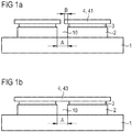
- FIG. 1a is a schematic sectional view of a modification of an optoelectronic semiconductor device described herein with a carrier 1 shown.
- the matrix-like semiconductor chips 2 are applied to the common carrier 1.
- the carrier 1 may be formed with a plastic, a ceramic or a metal.
- the carrier 1 is designed as a printed circuit board or, if the carrier 1 is metallic, as a carrier frame (leadframe) of the component.
- the semiconductor chips 2 are conductively connected to the carrier 1.
- the converter elements 3 are applied, which convert the primary radiation emitted by the semiconductor chips 2 radiation into radiation of different wavelengths.
- the converter elements 3 are each an optical CLC layer (chip level conversion layer) which partially converts the blue light primarily emitted by the semiconductor chips 2 into yellow light.
- the converter elements 3 can each be a layer of silicone or of transparent ceramic in which converter particles are introduced.
- Diffuser light scattering elements 4 in the form of light-scattering plates 41 are applied to the converter elements 3 and project beyond the length B laterally beyond the respective semiconductor chips 2.
- the light-scattering plates 41 project beyond the semiconductor chips 2 in each case by at most 75 ⁇ m.
- the light-scattering platelets 41 in the present case have a thickness of 750 ⁇ m.
- the material of the light-scattering plates 41 is a silicone, which was mixed before curing to the platelets 4 with radiation-scattering particles of alumina.
- the concentration of the alumina particles in the light-scattering plate 41 is 5% by weight.
- the radiation exit surface of the component is formed and fixed by the semiconductor chips 2 facing away from the upper sides of the light-scattering plate 41. Furthermore, a homogeneous color impression can be achieved over the entire radiation exit area, so that the component appears in accordance with a prescribable color impression for an external observer.
- the distance between the individual side surfaces of semiconductor chip to semiconductor chip is fixed at A and is in the range between 10 to 150 microns. In the present example, the distance A is 100 microns.
- the FIG. 1b shows an embodiment of the optoelectronic semiconductor device, in which the scattering element 4 is formed by a continuous layer.
- the scattering element 4 is formed by a continuous layer.
- it is a layer in the form of a coherent light-scattering film 43.
- the light-scattering film 43 has a thickness of 10 to 50 .mu.m, in the present case of 30 .mu.m.
- the light-diffusing film 43 is in turn formed with a transparent transparent to electromagnetic radiation silicone, in the prior to curing, the radiation-scattering particles of alumina in a concentration of 5% by weight were introduced.
- the light-scattering film 43 completely covers all semiconductor chips and interspaces 10 between the semiconductor chips when the component is viewed from above.
- the dark appearing interspaces 10 are superimposed with the scattering of the light-scattering film 43 also over areas of the interstices 10 starting diffused radiation. Due to the fact that the light-scattering film 43 is continuous and coherent in form of a layer, the interspaces 10 are superimposed or covered even more completely and uniformly by the electromagnetic radiation scattered by the light-diffusing film 43, than is the case in FIG FIG. 1a described embodiment is the case. Advantageously, it is thus avoided that an external observer can recognize and perceive the dark-appearing intermediate spaces 10 between the semiconductor chips. Advantageously, the other desired effects are achieved, as already described in the comments on the embodiment of FIG. 1a were called.
- such a scattering element 4 is suitable for a component with a large number of semiconductor chips 2, since the radiation exit surface is then large-area and thus not only the already mentioned advantageous luminous properties of the component come into effect, but the light-scattering film 43 in only a single Process step can be applied.
- This embodiment of the scattering element 4 is therefore not only cost, but also time-saving in their production.
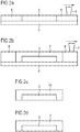
- FIG. 2a shows a film that serves as a carrier element 6 for the manufacturing process.
- a first template 5 is applied on the carrier element 6, a first template 5 is applied.
- a printing means in this example is a doctor blade 9, the material of the converter element 3 is introduced into the openings of the template 5.
- the material of the converter element 3 may be a layer of silicon or of a ceramic material into which converter particles are introduced.
- the stencil 5 is removed from the carrier element 6 and from the converter element 3.
- the converter element 3 forms a first layer on the carrier element 6.
- a second layer 7 is applied to the carrier element 6 and, by means of a second screen printing process using the doctor blade 9, a scattering element 4 is doctored onto the second template 8 as the second layer 7.
- the second layer 7 covers the converter element 3 on all exposed outer surfaces and is in direct contact with the converter element 3, see FIG. 2b .
- the second template 8 is removed both from the carrier element 6 and from the composite consisting of the converter element 3 and the second layer 7. For example, this is a converter layer that converts the light emitted by the converter element 3 into colored light.
- the process can be repeated and in a third or further step, the scattering element is applied to the second converter layer 7a.
- a viscous medium can be dropped onto the stencils 5 and 8, respectively.
- the material is subsequently distributed on the surface of the carrier element 6 and can then harden.
- the composite is subsequently applied to one of the semiconductor chips 2 in each case.
- the application can be done for example by means of platelet transfer and / or gluing.
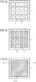
- FIG. 3a shows a schematic plan view of a carrier 1, on which the semiconductor chips 2 are located and are applied.
- the semiconductor chips 2 are arranged like a matrix in the form of rows and columns.
- FIG. 3b shows the matrix-like arranged semiconductor chips according to the FIG. 3a in which in addition to the semiconductor chips 2, the converter elements 3 were applied in the form of individual platelets.
- the application of the converter elements 3 on each one of the respective converter element associated semiconductor chip can be done by means of, for example, platelet transfer (also pick & place) and / or gluing.
- the Figure 3c shows the finished optoelectronic semiconductor device, in which the scattering element 4 in the form of a coherent layer, for example, the coherent light-scattering film 43, is applied to the matrix-like semiconductor chips 2 arranged.
- the light-scattering film 43 covers both the surfaces of the semiconductor chips 2 and all the gaps 10.
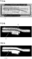
- FIG. 4a shows a schematic plan view of such an optoelectronic semiconductor device in switched off operating state.
- FIG. 4b shows a modification of the optoelectronic semiconductor device in the switched-on operating state without applied scattering elements.
- the brightly illuminated points show the emission surfaces of the semiconductor chips 2 that can be recognized by an external observer. Between the semiconductor chips 2 there are intermediate spaces 10, which appear darker. It can be seen that the luminance differences from semiconductor chip to gap are very prominent.
- Figure 4c shows the optoelectronic semiconductor device in the switched-on operating state, in which a scattering element 4 in the form of the continuous film 43 has been applied over the semiconductor chips 2.
- the scattering element 4 homogenizes the location-dependent luminance differences shown here.
- the partially still to be recognized bright luminous points show the recognizable for an external viewer emission surfaces of the semiconductor chip 2.
- the spaces 10 are no longer recognizable after application of the scattering element 4, so that the luminance differences from semiconductor chip to space can be avoided by the scattering element 4.
- the Figures 4d and 4f show plan views of such an optoelectronic device.
- FIG. 4d a component without scattering elements 4 is shown, in which the matrix-like arranged semiconductor chips 2 and the applied on the semiconductor chips 2 converter elements 3rd are recognizable.
- the grid-like, dark areas are the interstices 10 of the component.
- Figure 4e shows in a plan view of a finished optoelectronic device, in which the scattering element 4 forms a coherent film that covers all the semiconductor chips as well as all gaps 10 gapless. It turns out that the spaces 10 are much harder to recognize.
Landscapes
- Engineering & Computer Science (AREA)
- Power Engineering (AREA)
- Microelectronics & Electronic Packaging (AREA)
- Physics & Mathematics (AREA)
- Condensed Matter Physics & Semiconductors (AREA)
- General Physics & Mathematics (AREA)
- Computer Hardware Design (AREA)
- Led Device Packages (AREA)
- Solid State Image Pick-Up Elements (AREA)
- Light Receiving Elements (AREA)
Applications Claiming Priority (2)
| Application Number | Priority Date | Filing Date | Title |
|---|---|---|---|
| DE102009005907A DE102009005907A1 (de) | 2009-01-23 | 2009-01-23 | Optoelektronisches Halbleiterbauteil |
| PCT/EP2009/067888 WO2010083929A1 (de) | 2009-01-23 | 2009-12-23 | Optoelektronisches halbleiterbauteil |
Publications (2)
| Publication Number | Publication Date |
|---|---|
| EP2382673A1 EP2382673A1 (de) | 2011-11-02 |
| EP2382673B1 true EP2382673B1 (de) | 2019-01-30 |
Family
ID=41862160
Family Applications (1)
| Application Number | Title | Priority Date | Filing Date |
|---|---|---|---|
| EP09798937.0A Active EP2382673B1 (de) | 2009-01-23 | 2009-12-23 | Optoelektronisches halbleiterbauteil und verfahren zu seiner herstellung |
Country Status (8)
| Country | Link |
|---|---|
| US (1) | US8916886B2 (enExample) |
| EP (1) | EP2382673B1 (enExample) |
| JP (1) | JP5954991B2 (enExample) |
| KR (1) | KR101647866B1 (enExample) |
| CN (1) | CN102292836B (enExample) |
| DE (1) | DE102009005907A1 (enExample) |
| TW (1) | TWI420647B (enExample) |
| WO (1) | WO2010083929A1 (enExample) |
Families Citing this family (28)
| Publication number | Priority date | Publication date | Assignee | Title |
|---|---|---|---|---|
| DE102010034915A1 (de) | 2010-08-20 | 2012-02-23 | Osram Opto Semiconductors Gmbh | Optoelektronisches Halbleiterbauteil und Streukörper |
| DE102011013369A1 (de) * | 2010-12-30 | 2012-07-05 | Osram Opto Semiconductors Gmbh | Verfahren zum Herstellen einer Mehrzahl von Halbleiterbauelementen |
| DE102011050450A1 (de) | 2011-05-18 | 2012-11-22 | Osram Opto Semiconductors Gmbh | Optoelektronischer Halbleiterchip, optoelektronisches Halbleiterbauelement und Verfahren zur Herstellung eines optoelektronischen Halbleiterbauelements |
| DE102011087614A1 (de) * | 2011-12-02 | 2013-06-06 | Osram Opto Semiconductors Gmbh | Optoelektronische Anordnung |
| DE102012200973A1 (de) | 2012-01-24 | 2013-07-25 | Osram Opto Semiconductors Gmbh | Leuchte und verfahren zur herstellung einer leuchte |
| DE102012101892B4 (de) * | 2012-03-06 | 2021-05-12 | OSRAM Opto Semiconductors Gesellschaft mit beschränkter Haftung | Wellenlängenkonversionselement, Licht emittierendes Halbleiterbauelement und Anzeigevorrichtung damit sowie Verfahren zur Herstellung eines Wellenlängenkonversionselements |
| DE102012206970A1 (de) * | 2012-04-26 | 2013-10-31 | Osram Gmbh | Optische vorrichtung und beleuchtungseinrichtung |
| JP5960565B2 (ja) * | 2012-09-28 | 2016-08-02 | スタンレー電気株式会社 | 自動車ヘッドランプ用発光装置及びその製造方法 |
| JP6093611B2 (ja) * | 2013-03-18 | 2017-03-08 | スタンレー電気株式会社 | 発光装置及びその製造方法 |
| DE102013207460A1 (de) * | 2013-04-24 | 2014-10-30 | Osram Opto Semiconductors Gmbh | Optoelektronisches Bauelement |
| DE102013214877A1 (de) | 2013-07-30 | 2015-02-19 | Osram Opto Semiconductors Gmbh | Verfahren zum Herstellen eines Abdeckelements und eines optoelektronischen Bauelements, Abdeckelement und optoelektronisches Bauelement |
| DE102013214896B4 (de) * | 2013-07-30 | 2021-09-09 | OSRAM Opto Semiconductors Gesellschaft mit beschränkter Haftung | Verfahren zum Herstellen eines Konverterelements und eines optoelektronischen Bauelements, Konverterelement und optoelektronisches Bauelement |
| EP3036777B1 (en) | 2013-08-20 | 2020-03-11 | Lumileds Holding B.V. | Shaped phosphor to reduce repeated reflections |
| JP6079544B2 (ja) * | 2013-10-07 | 2017-02-15 | 豊田合成株式会社 | 発光装置および発光装置の製造方法 |
| US9499740B2 (en) | 2013-11-22 | 2016-11-22 | Nitto Denko Corporation | Light extraction element |
| DE102014102828A1 (de) * | 2014-03-04 | 2015-09-10 | Osram Opto Semiconductors Gmbh | Anordnung mit einer lichtemittierenden Diode |
| JP6757716B2 (ja) * | 2014-09-02 | 2020-09-23 | ルミレッズ ホールディング ベーフェー | 光源、その製造方法、及びライト |
| DE102014112883A1 (de) * | 2014-09-08 | 2016-03-10 | Osram Opto Semiconductors Gmbh | Optoelektronisches Bauteil |
| DE102014112973A1 (de) * | 2014-09-09 | 2016-03-10 | Osram Opto Semiconductors Gmbh | Optoelektronisches Bauteil |
| JP6552190B2 (ja) * | 2014-12-11 | 2019-07-31 | シチズン電子株式会社 | 発光装置及び発光装置の製造方法 |
| DE102015105474A1 (de) * | 2015-04-10 | 2016-10-13 | Osram Opto Semiconductors Gmbh | Konverterbauteil für eine optoelektronische Leuchtvorrichtung |
| DE102015106865A1 (de) * | 2015-05-04 | 2016-11-10 | Osram Opto Semiconductors Gmbh | Verfahren zum Herstellen eines Konverterbauteils |
| JP6217705B2 (ja) | 2015-07-28 | 2017-10-25 | 日亜化学工業株式会社 | 発光装置及びその製造方法 |
| JP2017224867A (ja) * | 2017-09-28 | 2017-12-21 | 日亜化学工業株式会社 | 発光装置及びその製造方法 |
| JP7083647B2 (ja) | 2018-01-16 | 2022-06-13 | スタンレー電気株式会社 | 発光装置 |
| US11489005B2 (en) | 2019-12-13 | 2022-11-01 | Lumileds Llc | Segmented LED arrays with diffusing elements |
| US11680696B2 (en) | 2019-12-13 | 2023-06-20 | Lumileds Llc | Segmented LED arrays with diffusing elements |
| JP7531090B2 (ja) * | 2022-04-28 | 2024-08-09 | 日亜化学工業株式会社 | 発光装置及び発光モジュール |
Citations (4)
| Publication number | Priority date | Publication date | Assignee | Title |
|---|---|---|---|---|
| JP2000022222A (ja) * | 1998-07-07 | 2000-01-21 | Stanley Electric Co Ltd | 発光ダイオード |
| JP2003110146A (ja) * | 2001-07-26 | 2003-04-11 | Matsushita Electric Works Ltd | 発光装置 |
| DE102007055170A1 (de) * | 2006-11-28 | 2008-06-12 | Cree, Inc. | Optische Vorformen für Festkörper-Lichtemissionswürfel und Verfahren und Systeme zu deren Herstellung und Zusammenbau |
| DE102008054029A1 (de) * | 2008-10-30 | 2010-05-06 | Osram Opto Semiconductors Gmbh | Optoelektronisches Halbleiterbauteil |
Family Cites Families (35)
| Publication number | Priority date | Publication date | Assignee | Title |
|---|---|---|---|---|
| JPS48102585A (enExample) * | 1972-04-04 | 1973-12-22 | ||
| JP3114805B2 (ja) | 1998-04-15 | 2000-12-04 | 日亜化学工業株式会社 | 面状光源及びそれを用いたディスプレイのバックライト、照光式操作スイッチ |
| DE19845229C1 (de) | 1998-10-01 | 2000-03-09 | Wustlich Daniel | Mit Weißlicht arbeitende Hintergrundbeleuchtung |
| US6271631B1 (en) | 1998-10-15 | 2001-08-07 | E.L. Specialists, Inc. | Alerting system using elastomeric EL lamp structure |
| GB2373368B (en) * | 2001-03-12 | 2004-10-27 | Arima Optoelectronics Corp | Light emitting devices |
| JP2003191521A (ja) | 2001-12-26 | 2003-07-09 | Kyocera Corp | 光プリンタヘッドの組立方法 |
| AU2003268980A1 (en) * | 2002-05-22 | 2003-12-02 | Applied Optotech Limited | Led array |
| JP4401681B2 (ja) * | 2003-05-19 | 2010-01-20 | 日東樹脂工業株式会社 | 光拡散体及びそれを用いた光学部材乃至光学デバイス |
| US7250715B2 (en) * | 2004-02-23 | 2007-07-31 | Philips Lumileds Lighting Company, Llc | Wavelength converted semiconductor light emitting devices |
| JP4360945B2 (ja) | 2004-03-10 | 2009-11-11 | シチズン電子株式会社 | 照明装置 |
| JP3983793B2 (ja) * | 2004-04-19 | 2007-09-26 | 松下電器産業株式会社 | Led照明光源の製造方法およびled照明光源 |
| JP4667803B2 (ja) * | 2004-09-14 | 2011-04-13 | 日亜化学工業株式会社 | 発光装置 |
| JP2006140362A (ja) * | 2004-11-15 | 2006-06-01 | Nitto Denko Corp | 光半導体素子封止用シートおよび該シートを用いた光半導体装置の製造方法 |
| US7344902B2 (en) * | 2004-11-15 | 2008-03-18 | Philips Lumileds Lighting Company, Llc | Overmolded lens over LED die |
| JP2006162846A (ja) | 2004-12-06 | 2006-06-22 | Asahi Glass Co Ltd | 直下型バックライト用拡散板 |
| US20060138938A1 (en) * | 2004-12-27 | 2006-06-29 | Tan Kheng L | White LED utilizing organic dyes |
| US7564180B2 (en) | 2005-01-10 | 2009-07-21 | Cree, Inc. | Light emission device and method utilizing multiple emitters and multiple phosphors |
| US7879258B2 (en) * | 2005-03-14 | 2011-02-01 | Koninklijke Philips Electronics N.V. | Phosphor in polycrystalline ceramic structure and a light-emitting element comprising same |
| KR100593933B1 (ko) | 2005-03-18 | 2006-06-30 | 삼성전기주식회사 | 산란 영역을 갖는 측면 방출형 발광다이오드 패키지 및이를 포함하는 백라이트 장치 |
| US7358543B2 (en) | 2005-05-27 | 2008-04-15 | Avago Technologies Ecbu Ip (Singapore) Pte. Ltd. | Light emitting device having a layer of photonic crystals and a region of diffusing material and method for fabricating the device |
| JP2007067204A (ja) * | 2005-08-31 | 2007-03-15 | Toshiba Lighting & Technology Corp | 発光ダイオード装置 |
| TWM289865U (en) * | 2005-11-08 | 2006-04-21 | Lighthouse Technology Co Ltd | Sectional light emitting diode backlight unit |
| JP4969119B2 (ja) * | 2006-03-20 | 2012-07-04 | 日本碍子株式会社 | 発光ダイオード装置 |
| DE102006024165A1 (de) * | 2006-05-23 | 2007-11-29 | Patent-Treuhand-Gesellschaft für elektrische Glühlampen mbH | Optoelektronischer Halbleiterchip mit einem Wellenlängenkonversionsstoff sowie optoelektronisches Halbleiterbauelement mit einem solchen Halbleiterchip und Verfahren zur Herstellung des optoelektronischen Halbleiterchips |
| CN101467266A (zh) | 2006-06-08 | 2009-06-24 | 皇家飞利浦电子股份有限公司 | 发光器件 |
| DE102007021009A1 (de) * | 2006-09-27 | 2008-04-10 | Osram Opto Semiconductors Gmbh | Leuchtdiodenanordnung und Verfahren zur Herstellung einer solchen |
| DE102006051746A1 (de) | 2006-09-29 | 2008-04-03 | Osram Opto Semiconductors Gmbh | Optoelektronisches Bauelement mit einer Lumineszenzkonversionsschicht |
| TWI338380B (en) * | 2006-10-11 | 2011-03-01 | Chuan Yu Hung | Light emitting diode incorporating high refractive index material |
| JP5392978B2 (ja) | 2006-10-30 | 2014-01-22 | 住友ベークライト株式会社 | 樹脂組成物および該樹脂組成物を用いて作製した半導体パッケージ |
| US7902560B2 (en) | 2006-12-15 | 2011-03-08 | Koninklijke Philips Electronics N.V. | Tunable white point light source using a wavelength converting element |
| CN201137827Y (zh) * | 2006-12-29 | 2008-10-22 | 东莞市科锐德数码光电科技有限公司 | 高光量led日光灯 |
| US9159888B2 (en) | 2007-01-22 | 2015-10-13 | Cree, Inc. | Wafer level phosphor coating method and devices fabricated utilizing method |
| US20080179618A1 (en) * | 2007-01-26 | 2008-07-31 | Ching-Tai Cheng | Ceramic led package |
| JP5158472B2 (ja) | 2007-05-24 | 2013-03-06 | スタンレー電気株式会社 | 半導体発光装置 |
| US8177382B2 (en) * | 2008-03-11 | 2012-05-15 | Cree, Inc. | Apparatus and methods for multiplanar optical diffusers and display panels for using the same |
-
2009
- 2009-01-23 DE DE102009005907A patent/DE102009005907A1/de not_active Withdrawn
- 2009-12-23 KR KR1020117019381A patent/KR101647866B1/ko active Active
- 2009-12-23 JP JP2011546655A patent/JP5954991B2/ja active Active
- 2009-12-23 WO PCT/EP2009/067888 patent/WO2010083929A1/de not_active Ceased
- 2009-12-23 EP EP09798937.0A patent/EP2382673B1/de active Active
- 2009-12-23 CN CN200980155142.2A patent/CN102292836B/zh active Active
- 2009-12-23 US US13/146,124 patent/US8916886B2/en active Active
-
2010
- 2010-01-21 TW TW099101615A patent/TWI420647B/zh not_active IP Right Cessation
Patent Citations (4)
| Publication number | Priority date | Publication date | Assignee | Title |
|---|---|---|---|---|
| JP2000022222A (ja) * | 1998-07-07 | 2000-01-21 | Stanley Electric Co Ltd | 発光ダイオード |
| JP2003110146A (ja) * | 2001-07-26 | 2003-04-11 | Matsushita Electric Works Ltd | 発光装置 |
| DE102007055170A1 (de) * | 2006-11-28 | 2008-06-12 | Cree, Inc. | Optische Vorformen für Festkörper-Lichtemissionswürfel und Verfahren und Systeme zu deren Herstellung und Zusammenbau |
| DE102008054029A1 (de) * | 2008-10-30 | 2010-05-06 | Osram Opto Semiconductors Gmbh | Optoelektronisches Halbleiterbauteil |
Also Published As
| Publication number | Publication date |
|---|---|
| US20120161162A1 (en) | 2012-06-28 |
| EP2382673A1 (de) | 2011-11-02 |
| US8916886B2 (en) | 2014-12-23 |
| JP2012516044A (ja) | 2012-07-12 |
| CN102292836B (zh) | 2016-05-25 |
| KR20110107384A (ko) | 2011-09-30 |
| WO2010083929A1 (de) | 2010-07-29 |
| CN102292836A (zh) | 2011-12-21 |
| DE102009005907A1 (de) | 2010-07-29 |
| JP5954991B2 (ja) | 2016-07-20 |
| TW201044549A (en) | 2010-12-16 |
| KR101647866B1 (ko) | 2016-08-11 |
| TWI420647B (zh) | 2013-12-21 |
Similar Documents
| Publication | Publication Date | Title |
|---|---|---|
| EP2382673B1 (de) | Optoelektronisches halbleiterbauteil und verfahren zu seiner herstellung | |
| EP2347456A1 (de) | Optoelektronisches halbleiterbauteil | |
| EP2561270B1 (de) | Flächenlichtquelle | |
| DE10010638A1 (de) | Verfahren zur Herstellung eines lichtabstrahlenden Halbleiterkörpers mit Lumineszenzkonversionselement | |
| DE102012105677B4 (de) | Leuchtdiodenmodul und Kfz-Scheinwerfer | |
| DE102008019926A1 (de) | Beleuchtungsvorrichtung und Verfahren zur Erzeugung einer flächigen Lichtausgabe | |
| DE102012102301A1 (de) | Optoelektronischer Halbleiterchip und Scheinwerfer mit einem solchen Halbleiterchip | |
| EP2845233B1 (de) | Led-modul | |
| DE102008019902A1 (de) | Optoelektronisches Bauelement und Herstellungsverfahren für ein optoelektronisches Bauelement | |
| WO2019145422A9 (de) | Optoelektronischer halbleiterchip, optoelektronisches bauelement und dessen verfahren zur herstellung | |
| WO2015014875A1 (de) | Verfahren zum herstellen eines konverterelements und eines optoelektronischen bauelements, konverterelement und optoelektronisches bauelement | |
| DE102018108423A1 (de) | Leuchtstoffrad und Beleuchtungsvorrichtung | |
| DE102019125255A1 (de) | Licht-emittierende Vorrichtung und Verfahren zu ihrer Herstellung | |
| AT12749U1 (de) | Leiterplattenelement mit wenigstens einer led | |
| WO2005100016A2 (de) | Lichtemittierendes paneel und optisch wirksame folie | |
| DE102014108362B4 (de) | Verfahren zur Herstellung mehrerer optoelektronischer Bauelemente und optoelektronisches Bauelement | |
| DE112022005250T5 (de) | Licht emittierende Vorrichtung und Verfahren zu deren Herstellung | |
| DE112018005607B4 (de) | Optoelektronischer Halbleiterchip und Verfahren zur Herstellung eines optoelektronischen Halbleiterchips | |
| DE102018125506A1 (de) | Optoelektronische Vorrichtung und Verfahren zur Herstellung von optoelektronischen Vorrichtungen | |
| DE102008027995B4 (de) | Lineare Lichtquelle | |
| DE102013205179A1 (de) | Verfahren zum Herstellen einer elektromagnetische Strahlung emittierenden Baugruppe und elektromagnetische Strahlung emittierende Baugruppe | |
| DE112019003660B4 (de) | Optoelektronisches bauelement und anzeigevorrichtung | |
| DE102014107473A1 (de) | Konverterelement zur Konvertierung einer Wellenlänge, optoelektronisches Bauelement mit Konverterelement und Verfahren zum Herstellen eines Konverterelements | |
| EP3123531B1 (de) | Led modul mit integrierter sekundäroptik | |
| DE102024109214A1 (de) | Verfahren zum Herstellen eines Konversionselements für ein optoelektronisches Bauelement und ein optoelektronisches Bauelement mit einem solchen Konversionselement |
Legal Events
| Date | Code | Title | Description |
|---|---|---|---|
| PUAI | Public reference made under article 153(3) epc to a published international application that has entered the european phase |
Free format text: ORIGINAL CODE: 0009012 |
|
| 17P | Request for examination filed |
Effective date: 20110725 |
|
| AK | Designated contracting states |
Kind code of ref document: A1 Designated state(s): AT BE BG CH CY CZ DE DK EE ES FI FR GB GR HR HU IE IS IT LI LT LU LV MC MK MT NL NO PL PT RO SE SI SK SM TR |
|
| DAX | Request for extension of the european patent (deleted) | ||
| 17Q | First examination report despatched |
Effective date: 20130725 |
|
| STAA | Information on the status of an ep patent application or granted ep patent |
Free format text: STATUS: EXAMINATION IS IN PROGRESS |
|
| GRAP | Despatch of communication of intention to grant a patent |
Free format text: ORIGINAL CODE: EPIDOSNIGR1 |
|
| STAA | Information on the status of an ep patent application or granted ep patent |
Free format text: STATUS: GRANT OF PATENT IS INTENDED |
|
| RIC1 | Information provided on ipc code assigned before grant |
Ipc: H01L 33/58 20100101ALN20180518BHEP Ipc: H01L 25/075 20060101AFI20180518BHEP Ipc: H01L 33/50 20100101ALN20180518BHEP |
|
| INTG | Intention to grant announced |
Effective date: 20180622 |
|
| RIC1 | Information provided on ipc code assigned before grant |
Ipc: H01L 33/58 20100101ALN20180611BHEP Ipc: H01L 25/075 20060101AFI20180611BHEP Ipc: H01L 33/50 20100101ALN20180611BHEP |
|
| GRAS | Grant fee paid |
Free format text: ORIGINAL CODE: EPIDOSNIGR3 |
|
| GRAJ | Information related to disapproval of communication of intention to grant by the applicant or resumption of examination proceedings by the epo deleted |
Free format text: ORIGINAL CODE: EPIDOSDIGR1 |
|
| GRAL | Information related to payment of fee for publishing/printing deleted |
Free format text: ORIGINAL CODE: EPIDOSDIGR3 |
|
| STAA | Information on the status of an ep patent application or granted ep patent |
Free format text: STATUS: EXAMINATION IS IN PROGRESS |
|
| REG | Reference to a national code |
Ref country code: DE Ref legal event code: R079 Ref document number: 502009015604 Country of ref document: DE Free format text: PREVIOUS MAIN CLASS: H01L0033500000 Ipc: H01L0025075000 |
|
| INTC | Intention to grant announced (deleted) | ||
| RIC1 | Information provided on ipc code assigned before grant |
Ipc: H01L 33/58 20100101ALN20181003BHEP Ipc: H01L 25/075 20060101AFI20181003BHEP Ipc: H01L 33/50 20100101ALN20181003BHEP |
|
| GRAR | Information related to intention to grant a patent recorded |
Free format text: ORIGINAL CODE: EPIDOSNIGR71 |
|
| STAA | Information on the status of an ep patent application or granted ep patent |
Free format text: STATUS: GRANT OF PATENT IS INTENDED |
|
| INTG | Intention to grant announced |
Effective date: 20181112 |
|
| GRAA | (expected) grant |
Free format text: ORIGINAL CODE: 0009210 |
|
| STAA | Information on the status of an ep patent application or granted ep patent |
Free format text: STATUS: THE PATENT HAS BEEN GRANTED |
|
| AK | Designated contracting states |
Kind code of ref document: B1 Designated state(s): AT BE BG CH CY CZ DE DK EE ES FI FR GB GR HR HU IE IS IT LI LT LU LV MC MK MT NL NO PL PT RO SE SI SK SM TR |
|
| REG | Reference to a national code |
Ref country code: GB Ref legal event code: FG4D Free format text: NOT ENGLISH |
|
| REG | Reference to a national code |
Ref country code: CH Ref legal event code: EP |
|
| REG | Reference to a national code |
Ref country code: AT Ref legal event code: REF Ref document number: 1093937 Country of ref document: AT Kind code of ref document: T Effective date: 20190215 |
|
| REG | Reference to a national code |
Ref country code: IE Ref legal event code: FG4D Free format text: LANGUAGE OF EP DOCUMENT: GERMAN |
|
| REG | Reference to a national code |
Ref country code: DE Ref legal event code: R096 Ref document number: 502009015604 Country of ref document: DE |
|
| REG | Reference to a national code |
Ref country code: LT Ref legal event code: MG4D |
|
| REG | Reference to a national code |
Ref country code: NL Ref legal event code: MP Effective date: 20190130 |
|
| PG25 | Lapsed in a contracting state [announced via postgrant information from national office to epo] |
Ref country code: ES Free format text: LAPSE BECAUSE OF FAILURE TO SUBMIT A TRANSLATION OF THE DESCRIPTION OR TO PAY THE FEE WITHIN THE PRESCRIBED TIME-LIMIT Effective date: 20190130 Ref country code: NL Free format text: LAPSE BECAUSE OF FAILURE TO SUBMIT A TRANSLATION OF THE DESCRIPTION OR TO PAY THE FEE WITHIN THE PRESCRIBED TIME-LIMIT Effective date: 20190130 Ref country code: SE Free format text: LAPSE BECAUSE OF FAILURE TO SUBMIT A TRANSLATION OF THE DESCRIPTION OR TO PAY THE FEE WITHIN THE PRESCRIBED TIME-LIMIT Effective date: 20190130 Ref country code: PT Free format text: LAPSE BECAUSE OF FAILURE TO SUBMIT A TRANSLATION OF THE DESCRIPTION OR TO PAY THE FEE WITHIN THE PRESCRIBED TIME-LIMIT Effective date: 20190530 Ref country code: FI Free format text: LAPSE BECAUSE OF FAILURE TO SUBMIT A TRANSLATION OF THE DESCRIPTION OR TO PAY THE FEE WITHIN THE PRESCRIBED TIME-LIMIT Effective date: 20190130 Ref country code: NO Free format text: LAPSE BECAUSE OF FAILURE TO SUBMIT A TRANSLATION OF THE DESCRIPTION OR TO PAY THE FEE WITHIN THE PRESCRIBED TIME-LIMIT Effective date: 20190430 Ref country code: PL Free format text: LAPSE BECAUSE OF FAILURE TO SUBMIT A TRANSLATION OF THE DESCRIPTION OR TO PAY THE FEE WITHIN THE PRESCRIBED TIME-LIMIT Effective date: 20190130 Ref country code: LT Free format text: LAPSE BECAUSE OF FAILURE TO SUBMIT A TRANSLATION OF THE DESCRIPTION OR TO PAY THE FEE WITHIN THE PRESCRIBED TIME-LIMIT Effective date: 20190130 |
|
| PG25 | Lapsed in a contracting state [announced via postgrant information from national office to epo] |
Ref country code: IS Free format text: LAPSE BECAUSE OF FAILURE TO SUBMIT A TRANSLATION OF THE DESCRIPTION OR TO PAY THE FEE WITHIN THE PRESCRIBED TIME-LIMIT Effective date: 20190530 Ref country code: HR Free format text: LAPSE BECAUSE OF FAILURE TO SUBMIT A TRANSLATION OF THE DESCRIPTION OR TO PAY THE FEE WITHIN THE PRESCRIBED TIME-LIMIT Effective date: 20190130 Ref country code: GR Free format text: LAPSE BECAUSE OF FAILURE TO SUBMIT A TRANSLATION OF THE DESCRIPTION OR TO PAY THE FEE WITHIN THE PRESCRIBED TIME-LIMIT Effective date: 20190501 Ref country code: LV Free format text: LAPSE BECAUSE OF FAILURE TO SUBMIT A TRANSLATION OF THE DESCRIPTION OR TO PAY THE FEE WITHIN THE PRESCRIBED TIME-LIMIT Effective date: 20190130 Ref country code: BG Free format text: LAPSE BECAUSE OF FAILURE TO SUBMIT A TRANSLATION OF THE DESCRIPTION OR TO PAY THE FEE WITHIN THE PRESCRIBED TIME-LIMIT Effective date: 20190430 |
|
| RAP2 | Party data changed (patent owner data changed or rights of a patent transferred) |
Owner name: OSRAM OPTO SEMICONDUCTORS GMBH |
|
| PG25 | Lapsed in a contracting state [announced via postgrant information from national office to epo] |
Ref country code: CZ Free format text: LAPSE BECAUSE OF FAILURE TO SUBMIT A TRANSLATION OF THE DESCRIPTION OR TO PAY THE FEE WITHIN THE PRESCRIBED TIME-LIMIT Effective date: 20190130 Ref country code: IT Free format text: LAPSE BECAUSE OF FAILURE TO SUBMIT A TRANSLATION OF THE DESCRIPTION OR TO PAY THE FEE WITHIN THE PRESCRIBED TIME-LIMIT Effective date: 20190130 Ref country code: RO Free format text: LAPSE BECAUSE OF FAILURE TO SUBMIT A TRANSLATION OF THE DESCRIPTION OR TO PAY THE FEE WITHIN THE PRESCRIBED TIME-LIMIT Effective date: 20190130 Ref country code: DK Free format text: LAPSE BECAUSE OF FAILURE TO SUBMIT A TRANSLATION OF THE DESCRIPTION OR TO PAY THE FEE WITHIN THE PRESCRIBED TIME-LIMIT Effective date: 20190130 Ref country code: EE Free format text: LAPSE BECAUSE OF FAILURE TO SUBMIT A TRANSLATION OF THE DESCRIPTION OR TO PAY THE FEE WITHIN THE PRESCRIBED TIME-LIMIT Effective date: 20190130 Ref country code: SK Free format text: LAPSE BECAUSE OF FAILURE TO SUBMIT A TRANSLATION OF THE DESCRIPTION OR TO PAY THE FEE WITHIN THE PRESCRIBED TIME-LIMIT Effective date: 20190130 |
|
| REG | Reference to a national code |
Ref country code: DE Ref legal event code: R097 Ref document number: 502009015604 Country of ref document: DE |
|
| PG25 | Lapsed in a contracting state [announced via postgrant information from national office to epo] |
Ref country code: SM Free format text: LAPSE BECAUSE OF FAILURE TO SUBMIT A TRANSLATION OF THE DESCRIPTION OR TO PAY THE FEE WITHIN THE PRESCRIBED TIME-LIMIT Effective date: 20190130 |
|
| PLBE | No opposition filed within time limit |
Free format text: ORIGINAL CODE: 0009261 |
|
| STAA | Information on the status of an ep patent application or granted ep patent |
Free format text: STATUS: NO OPPOSITION FILED WITHIN TIME LIMIT |
|
| 26N | No opposition filed |
Effective date: 20191031 |
|
| PG25 | Lapsed in a contracting state [announced via postgrant information from national office to epo] |
Ref country code: SI Free format text: LAPSE BECAUSE OF FAILURE TO SUBMIT A TRANSLATION OF THE DESCRIPTION OR TO PAY THE FEE WITHIN THE PRESCRIBED TIME-LIMIT Effective date: 20190130 |
|
| PG25 | Lapsed in a contracting state [announced via postgrant information from national office to epo] |
Ref country code: TR Free format text: LAPSE BECAUSE OF FAILURE TO SUBMIT A TRANSLATION OF THE DESCRIPTION OR TO PAY THE FEE WITHIN THE PRESCRIBED TIME-LIMIT Effective date: 20190130 |
|
| REG | Reference to a national code |
Ref country code: CH Ref legal event code: PL |
|
| REG | Reference to a national code |
Ref country code: BE Ref legal event code: MM Effective date: 20191231 |
|
| PG25 | Lapsed in a contracting state [announced via postgrant information from national office to epo] |
Ref country code: MC Free format text: LAPSE BECAUSE OF FAILURE TO SUBMIT A TRANSLATION OF THE DESCRIPTION OR TO PAY THE FEE WITHIN THE PRESCRIBED TIME-LIMIT Effective date: 20190130 |
|
| GBPC | Gb: european patent ceased through non-payment of renewal fee |
Effective date: 20191223 |
|
| PG25 | Lapsed in a contracting state [announced via postgrant information from national office to epo] |
Ref country code: LU Free format text: LAPSE BECAUSE OF NON-PAYMENT OF DUE FEES Effective date: 20191223 Ref country code: IE Free format text: LAPSE BECAUSE OF NON-PAYMENT OF DUE FEES Effective date: 20191223 Ref country code: FR Free format text: LAPSE BECAUSE OF NON-PAYMENT OF DUE FEES Effective date: 20191231 Ref country code: GB Free format text: LAPSE BECAUSE OF NON-PAYMENT OF DUE FEES Effective date: 20191223 |
|
| PG25 | Lapsed in a contracting state [announced via postgrant information from national office to epo] |
Ref country code: LI Free format text: LAPSE BECAUSE OF NON-PAYMENT OF DUE FEES Effective date: 20191231 Ref country code: CH Free format text: LAPSE BECAUSE OF NON-PAYMENT OF DUE FEES Effective date: 20191231 Ref country code: BE Free format text: LAPSE BECAUSE OF NON-PAYMENT OF DUE FEES Effective date: 20191231 |
|
| REG | Reference to a national code |
Ref country code: AT Ref legal event code: MM01 Ref document number: 1093937 Country of ref document: AT Kind code of ref document: T Effective date: 20191223 |
|
| PG25 | Lapsed in a contracting state [announced via postgrant information from national office to epo] |
Ref country code: CY Free format text: LAPSE BECAUSE OF FAILURE TO SUBMIT A TRANSLATION OF THE DESCRIPTION OR TO PAY THE FEE WITHIN THE PRESCRIBED TIME-LIMIT Effective date: 20190130 Ref country code: AT Free format text: LAPSE BECAUSE OF NON-PAYMENT OF DUE FEES Effective date: 20191223 |
|
| PG25 | Lapsed in a contracting state [announced via postgrant information from national office to epo] |
Ref country code: MT Free format text: LAPSE BECAUSE OF FAILURE TO SUBMIT A TRANSLATION OF THE DESCRIPTION OR TO PAY THE FEE WITHIN THE PRESCRIBED TIME-LIMIT Effective date: 20190130 Ref country code: HU Free format text: LAPSE BECAUSE OF FAILURE TO SUBMIT A TRANSLATION OF THE DESCRIPTION OR TO PAY THE FEE WITHIN THE PRESCRIBED TIME-LIMIT; INVALID AB INITIO Effective date: 20091223 |
|
| PG25 | Lapsed in a contracting state [announced via postgrant information from national office to epo] |
Ref country code: MK Free format text: LAPSE BECAUSE OF FAILURE TO SUBMIT A TRANSLATION OF THE DESCRIPTION OR TO PAY THE FEE WITHIN THE PRESCRIBED TIME-LIMIT Effective date: 20190130 |
|
| P01 | Opt-out of the competence of the unified patent court (upc) registered |
Effective date: 20230825 |
|
| REG | Reference to a national code |
Ref country code: DE Ref legal event code: R079 Ref document number: 502009015604 Country of ref document: DE Free format text: PREVIOUS MAIN CLASS: H01L0025075000 Ipc: H10H0029240000 |
|
| PGFP | Annual fee paid to national office [announced via postgrant information from national office to epo] |
Ref country code: DE Payment date: 20241210 Year of fee payment: 16 |