EP2342155B1 - Appareil de chariot à fourches pour véhicule de manutention de matériaux - Google Patents
Appareil de chariot à fourches pour véhicule de manutention de matériaux Download PDFInfo
- Publication number
- EP2342155B1 EP2342155B1 EP09792427.8A EP09792427A EP2342155B1 EP 2342155 B1 EP2342155 B1 EP 2342155B1 EP 09792427 A EP09792427 A EP 09792427A EP 2342155 B1 EP2342155 B1 EP 2342155B1
- Authority
- EP
- European Patent Office
- Prior art keywords
- fork
- carriage
- fork carriage
- materials handling
- monomast
- Prior art date
- Legal status (The legal status is an assumption and is not a legal conclusion. Google has not performed a legal analysis and makes no representation as to the accuracy of the status listed.)
- Active
Links
- 238000005007 materials handling Methods 0.000 title claims description 27
- 239000012530 fluid Substances 0.000 description 21
- 230000008878 coupling Effects 0.000 description 14
- 238000010168 coupling process Methods 0.000 description 14
- 238000005859 coupling reaction Methods 0.000 description 14
- 230000000694 effects Effects 0.000 description 9
- 239000002184 metal Substances 0.000 description 3
- 239000007787 solid Substances 0.000 description 2
- 230000002411 adverse Effects 0.000 description 1
- 238000005452 bending Methods 0.000 description 1
- 238000006073 displacement reaction Methods 0.000 description 1
- 230000004048 modification Effects 0.000 description 1
- 238000012986 modification Methods 0.000 description 1
Images


Classifications
-
- B—PERFORMING OPERATIONS; TRANSPORTING
- B66—HOISTING; LIFTING; HAULING
- B66F—HOISTING, LIFTING, HAULING OR PUSHING, NOT OTHERWISE PROVIDED FOR, e.g. DEVICES WHICH APPLY A LIFTING OR PUSHING FORCE DIRECTLY TO THE SURFACE OF A LOAD
- B66F9/00—Devices for lifting or lowering bulky or heavy goods for loading or unloading purposes
- B66F9/06—Devices for lifting or lowering bulky or heavy goods for loading or unloading purposes movable, with their loads, on wheels or the like, e.g. fork-lift trucks
- B66F9/075—Constructional features or details
- B66F9/12—Platforms; Forks; Other load supporting or gripping members
- B66F9/14—Platforms; Forks; Other load supporting or gripping members laterally movable, e.g. swingable, for slewing or transverse movements
- B66F9/147—Whole unit including fork support moves relative to mast
- B66F9/148—Whole unit including fork support moves sideways
-
- B—PERFORMING OPERATIONS; TRANSPORTING
- B66—HOISTING; LIFTING; HAULING
- B66F—HOISTING, LIFTING, HAULING OR PUSHING, NOT OTHERWISE PROVIDED FOR, e.g. DEVICES WHICH APPLY A LIFTING OR PUSHING FORCE DIRECTLY TO THE SURFACE OF A LOAD
- B66F9/00—Devices for lifting or lowering bulky or heavy goods for loading or unloading purposes
- B66F9/06—Devices for lifting or lowering bulky or heavy goods for loading or unloading purposes movable, with their loads, on wheels or the like, e.g. fork-lift trucks
- B66F9/075—Constructional features or details
-
- B—PERFORMING OPERATIONS; TRANSPORTING
- B66—HOISTING; LIFTING; HAULING
- B66F—HOISTING, LIFTING, HAULING OR PUSHING, NOT OTHERWISE PROVIDED FOR, e.g. DEVICES WHICH APPLY A LIFTING OR PUSHING FORCE DIRECTLY TO THE SURFACE OF A LOAD
- B66F9/00—Devices for lifting or lowering bulky or heavy goods for loading or unloading purposes
- B66F9/06—Devices for lifting or lowering bulky or heavy goods for loading or unloading purposes movable, with their loads, on wheels or the like, e.g. fork-lift trucks
- B66F9/075—Constructional features or details
- B66F9/08—Masts; Guides; Chains
- B66F9/087—Monomasts
-
- B—PERFORMING OPERATIONS; TRANSPORTING
- B66—HOISTING; LIFTING; HAULING
- B66F—HOISTING, LIFTING, HAULING OR PUSHING, NOT OTHERWISE PROVIDED FOR, e.g. DEVICES WHICH APPLY A LIFTING OR PUSHING FORCE DIRECTLY TO THE SURFACE OF A LOAD
- B66F9/00—Devices for lifting or lowering bulky or heavy goods for loading or unloading purposes
- B66F9/06—Devices for lifting or lowering bulky or heavy goods for loading or unloading purposes movable, with their loads, on wheels or the like, e.g. fork-lift trucks
- B66F9/075—Constructional features or details
- B66F9/08—Masts; Guides; Chains
- B66F9/10—Masts; Guides; Chains movable in a horizontal direction relative to truck
-
- B—PERFORMING OPERATIONS; TRANSPORTING
- B66—HOISTING; LIFTING; HAULING
- B66F—HOISTING, LIFTING, HAULING OR PUSHING, NOT OTHERWISE PROVIDED FOR, e.g. DEVICES WHICH APPLY A LIFTING OR PUSHING FORCE DIRECTLY TO THE SURFACE OF A LOAD
- B66F9/00—Devices for lifting or lowering bulky or heavy goods for loading or unloading purposes
- B66F9/06—Devices for lifting or lowering bulky or heavy goods for loading or unloading purposes movable, with their loads, on wheels or the like, e.g. fork-lift trucks
- B66F9/075—Constructional features or details
- B66F9/12—Platforms; Forks; Other load supporting or gripping members
- B66F9/122—Platforms; Forks; Other load supporting or gripping members longitudinally movable
-
- B—PERFORMING OPERATIONS; TRANSPORTING
- B66—HOISTING; LIFTING; HAULING
- B66F—HOISTING, LIFTING, HAULING OR PUSHING, NOT OTHERWISE PROVIDED FOR, e.g. DEVICES WHICH APPLY A LIFTING OR PUSHING FORCE DIRECTLY TO THE SURFACE OF A LOAD
- B66F9/00—Devices for lifting or lowering bulky or heavy goods for loading or unloading purposes
- B66F9/06—Devices for lifting or lowering bulky or heavy goods for loading or unloading purposes movable, with their loads, on wheels or the like, e.g. fork-lift trucks
- B66F9/075—Constructional features or details
- B66F9/20—Means for actuating or controlling masts, platforms, or forks
- B66F9/22—Hydraulic devices or systems
-
- B—PERFORMING OPERATIONS; TRANSPORTING
- B66—HOISTING; LIFTING; HAULING
- B66F—HOISTING, LIFTING, HAULING OR PUSHING, NOT OTHERWISE PROVIDED FOR, e.g. DEVICES WHICH APPLY A LIFTING OR PUSHING FORCE DIRECTLY TO THE SURFACE OF A LOAD
- B66F9/00—Devices for lifting or lowering bulky or heavy goods for loading or unloading purposes
- B66F9/06—Devices for lifting or lowering bulky or heavy goods for loading or unloading purposes movable, with their loads, on wheels or the like, e.g. fork-lift trucks
- B66F9/075—Constructional features or details
- B66F9/08—Masts; Guides; Chains
- B66F9/082—Masts; Guides; Chains inclinable
Definitions
- the present invention relates to a materials handling vehicle comprising a fork carriage apparatus and, more particularly, to such a vehicle including a power unit and a monomast coupled to the power unit and supporting a fork carriage apparatus including a fork carriage assembly wherein a reach mechanism is provided for effecting movement of the fork carriage assembly between an extended position and a compact retracted position.
- U.S. Patent No. 4,552,250 to Luebrecht discloses a lift truck including a monomast comprising an outer, movable mast mounted to telescope over an inner mast which is fixed to a frame.
- Each mast is configured to have a substantially continuous, unitary tubular body to provide strength for resisting torsional and bending loads applied to the mast.
- U.S. Patent No. 5,022,496 to Klopkins et al. discloses a materials handling vehicle including a telescoping monomast structure supporting a vertically movable platform assembly.
- the platform assembly supports a pair of extendable forks carried by a fork carriage assembly.
- An auxiliary lift cylinder is provided to move the forks vertically relative to the platform assembly.
- U.S. Patent No. 5,738,187 to Dammeyer et al. discloses a fork lift truck including a mast assembly formed by a pair of stationary channel members and nested movable channel members. A pair of forks is supported on a fork carriage that is mounted to the mast assembly by a scissors reach mechanism. The scissors reach mechanism is supported to a vertically movable carriage assembly located between the channel members of the mast assembly.
- U.S. Patent No. 6,851,915 to Warner et al. discloses a load handling device for an industrial truck.
- the load handling device is described as comprising a lift carriage that is guided on the outer sides of a lift frame by rollers.
- Load forks are supported on a reach carriage, and the reach carriage includes guide rails engaged with rollers on the outer sides of the lift carriage.
- a pair of hydraulic cylinders actuate the reach carriage to displace the load forks in a longitudinal direction of the industrial truck.
- DE 1131146 B describes a materials handling vehicle according to the preamble of claim 1, comprising a vehicle power unit and a mast coupled to the vehicle power unit.
- a load carrier such as forks, is coupled to a rotary carriage for vertical movement along and around the mast.
- the load carrier may be mounted on a reach mechanism to allow horizontal displacement of the forks relative to the mast.
- An improved fork carriage apparatus for a materials handling vehicle is desired to provide a reach mechanism on a materials handling vehicle having a monomast structure without adversely increasing the overall longitudinal length of the vehicle.
- a materials handling vehicle comprising a vehicle power unit; a monomast coupled to the vehicle power unit; and a fork carriage apparatus supported on the monomast; the fork carriage apparatus comprising a mast carriage assembly movably coupled to the monomast; a fork carriage mechanism to which forks are mounted; and a reach mechanism coupled to the mast carriage assembly and the fork carriage mechanism for effecting movement of the fork carriage mechanism between an extended position and a retracted position, characterised in that the mast carriage assembly includes at least one carriage frame member extending laterally across a front side of said monomast, and the reach mechanism includes at least one laterally extending cross member which is located in vertically spaced relation to the carriage frame member when the fork carriage mechanism is in the retracted position.
- the at least one carriage frame member may comprise first and second carriage frame members extending laterally across the front side of the monomast, and the cross member may be located between the first and second carriage frame members when the fork carriage mechanism is in the retracted position.
- the carriage frame member and the cross member may intersect a common vertical plane extending in front of and generally parallel to the monomast when the fork carriage mechanism is in the retracted position.
- the reach mechanism may comprise a plurality of cross members and the carriage frame member may be located between two of the cross members when the fork carriage mechanism is in the retracted position.
- the fork carriage mechanism may include at least one laterally extending fork frame member, and the fork frame member may be located between the two cross members when the fork carriage mechanism is in the retracted position.
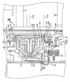
- Fig. 1 illustrates a top view of a rider reach truck 100.
- a monomast 200, a fork carriage apparatus 300 and a fork carriage apparatus lift structure 400, constructed in accordance with the present invention, are incorporated into the rider reach truck 100, see also Fig. 3 .
- the present invention is described herein with reference to the rider reach truck 100, it will be apparent to those skilled in the art that the invention and variations of the invention can be more generally applied to a variety of other materials handling vehicles, such as a sit-down counterbalanced truck or a stand-up counterbalanced truck.
- the truck 100 further includes a vehicle power unit 102, see Figs. 1 and 2 , including a longitudinal centerline CL 100 , see Fig. 1 .
- the power unit 102 houses a battery (not shown) for supplying power to a traction motor coupled to a steerable wheel (not shown) mounted near a first corner at the rear 102A of the power unit 102. Mounted to a second corner at the rear 102A of the power unit 102 is a caster wheel (not shown).
- a pair of outriggers 202 and 204 are mounted to a mohomasfframe 210, see Fig. 2 .
- the outriggers 202 and 204 are provided with supports wheels 202A and 204A.
- the battery also supplies power to a motor (not shown), which drives a hydraulic pump (not shown).
- the pump supplies pressurized hydraulic fluid to the fork carriage lift apparatus structure 400 and to a mast weldment lift structure (not shown).
- the vehicle power unit 102 includes an operator's compartment 110, which, in the illustrated embodiment, is positioned on a side of the longitudinal centerline CL 100 of the vehicle power unit 102 opposite a side where the monomast 200 is positioned, see Fig. 1 .
- An operator standing in the compartment 110 may control the direction of travel of the truck 100 via a tiller 120.
- the operator may also control the travel speed of the truck 100, and height, extension, tilt and side shift of first and second forks 402 and 404 via a multifunction controller 130, see Fig. 1 .
- the first and second forks 402 and 404 form part of the fork carriage apparatus 300.
- the monomast 200 has a longitudinal centerline CL 200 , see Fig. 1 .
- the monomast longitudinal centerline CL 200 is offset from, i.e., spaced laterally from, the longitudinal centerline CL 100 of the vehicle power unit 102. Further, the monomast longitudinal centerline CL 200 is substantially parallel with the longitudinal centerline CL 100 of the vehicle power unit 102.
- the monomast longitudinal centerline CL 200 is not angled or oblique to the longitudinal centerline CL 100 of the vehicle power unit 102, the overall length of the truck 100 in a direction parallel to the monomast longitudinal centerline CL 200 can be minimized, i.e., made shorter than a truck including a monomast having a longitudinal centerline that is not parallel to a longitudinal centerline of the vehicle power unit.
- the monomast longitudinal centerline CL 200 is laterally offset approximately 8 inches from the longitudinal centerline CL 200 of the vehicle power unit 102, see arrow LO in Fig. 1 , wherein the vehicle power unit 102 has a width W of about 42 inches. These dimensions can be varied, as will be apparent to one skilled in the art.
- the monomast 200 comprises a first stage weldment 230, a second stage weldment 240 positioned to telescope over the first stage weldment 230 and a third stage weldment 250 positioned to telescope over the first and second stage weldments 230 and 240, see Fig. 3 .
- the monomast 200 may be constructed in essentially the same manner as the monomast disclosed in US 2010/0065377 A1 entitled MONOMAST FOR A MATERIALS HANDLING VEHICLE.
- the monomast 200 further comprises a mast weldment lift structure (not shown), which effects staged lifting movement of the second and third stage weldments 230 and 240 relative to the first stage weldment 230.
- the mast weldment lift structure may be constructed in the same manner as the mast weldment lift structure set out in US 2010/0065377 A1 entitled MONOMAST FOR A MATERIALS HANDLING VEHICLE.
- the monomast 200 comprises a single structure having a unitary tubular form and does not comprise spaced-apart vertical channels or rails joined by horizontal members wherein an open area is located between the spaced-apart vertical channels or rails.
- the fork carriage apparatus 300 is coupled to the third stage weldment 250 so as to move vertically relative to the third stage weldment 250, see Fig. 4 .
- the fork carriage apparatus 300 also moves vertically with the third stage weldment 250 relative to the first and second stage weldments 230 and 240.
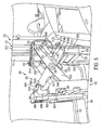
- the fork carriage apparatus 300 comprises a fork carriage mechanism 310 to which the first and second forks 402 and 404 are mounted, see Fig. 5 .
- the fork carriage mechanism 310 is mounted to a reach mechanism 320 which, in turn, is mounted to a mast carriage assembly 330, see Figs. 4 and 5 .
- the mast carriage assembly 330 comprises a main unit 332 including first and second side members 336A and 336B, see Figs.
- the main unit 332 further comprises first, second, third and fourth vertically spaced apart and horizontally extending carriage frame members 332A, 332B, 332C and 332D extending across a front side FS of the monomast 200, see Figs. 4 , 5 and 6 .
- the carriage frame members 332A, 332B, 332C, 332D are rigidly attached to the side members 336A and 336B.
- the reach mechanism 320 comprises a pantograph or scissors structure having first and second inner arms 342A and 342B, and first and second outer arms 352A and 352B.
- the first and second inner arms 342A and 342B include first ends 344A and 344B directly coupled to the side members 336A and 336B of the mast carriage assembly 330, and second ends 346A and 346B pivotally coupled to the fork carriage mechanism 310.
- Each of the first ends 344A and 344B includes a roller 368.
- the rollers 368 are received in vertically extending tracks 370 formed in the outer sides of the side members 336A and 336B.
- the rollers 368 engaged within the tracks 370 form a sliding coupling between the first ends 344A and 344B of the inner arms 342A and 342B and the side members 336A and 336B.
- the first and second outer arms 352A and 352B include first ends 354A and 354B directly coupled to the side members 336A and 336B of the mast carriage assembly 330, and second ends 356A and 356B pivotally coupled to the fork carriage mechanism 310, see Figs. 4 , 5 , 6 and 7 .
- Each of the side members 336A and 336B includes a pivot location 372 where the first ends 354A and 354B of the first and second outer arms 352A and 352B are coupled to the side members 336A and 336B, see Figs. 4 and 5 .
- the first and second inner arms 342A and 342B are coupled to the first and second outer arms 352A and 352B at pivot connections 358, see Figs. 4 , 5 and 6 .
- a hydraulic piston/cylinder apparatus 373 is provided for effecting movement of the reach mechanism 320.
- the piston/cylinder apparatus 373 comprises a cylinder 374 extending from each of the side members 336A and 336B and including a ram 376 extending to a coupling tab 378 provided on each of the first and second outer arms 352A and 352B, see Figs. 4 , 5 , 6 , 7 and 8 .
- Movement of the rams 376 out of the cylinders 374 effects pivotal movement of the outer arms 352A and 352B outwardly from the side members 336A and 336B to move the fork carriage mechanism 310 in a longitudinal direction, as designated by arrow LD in Fig. 7 , to an extended position, see Figs. 4 and 5 .
- Movement of the rams 376 into the cylinders 374 effects movement of the fork carriage mechanism 310 to a retracted position locating the fork carriage mechanism 310 adjacent to the monomast 200, see Figs. 7 and 8 .
- the piston/cylinder apparatus 373 may be coupled to the first and second inner arms 342A, 342B instead of the first and second outer arms 352A, 352B.
- the fork carriage mechanism 310 generally comprises in the illustrated embodiment a pair of vertical plates 380A and 380B and first, second and third vertically spaced apart fork frame members 382A, 382B and 382C attached to the vertical plates 380A and 380B, and first and second L-shaped supports 398A and 398B coupled to the first fork frame member 382A, see Figs. 5 , 6 and 7 .
- the second ends 346A and 346B of the first and second inner arms 342A and 342B are attached to the L-shaped supports 398A and 398B at connection locations 386, and the second ends 356A and 356B of the first and second outer arms 352A and 352B are attached to the vertical plates 380A and 380B at connection locations 388, see Figs. 5 , 6 and 8 (only the connection of outer arm 352B to vertical plate 380B is shown in the drawings).
- the forks 402 and 404 are supported on the second fork frame member 3 82B via a side shift structure 384 forming part of the carriage frame mechanism 310.
- the side shift structure 384 comprises a conventional side shift apparatus that allows the forks 402 and 404 to be manually moved toward or away from each other or in unison side-to-side along a transverse axis 392, see Fig. 8 .
- a cross member structure 360 extends between the first and second inner arms 342A and 342-B and comprises in the illustrated embodiment first, second, third and fourth laterally extending cross members 362A, 362B, 362C and 362D, see Fig. 6 .
- the lateral edges or ends of the cross members 362A, 362B, 362C and 362D are preferably attached at or adjacent to front edges 364A and 364B of the inner arms 342A and 342B, see Figs. 4 and 6 .
- the cross members 362A, 362B, 362C and 362D are generally aligned in a common cross member plane P 300 extending adjacent to the front edges 364A and 364B of the inner arms 342A and 342B, see Fig. 6 .
- the cross member structure 360 together with the inner arms 342A and 342B define an inner arm weldment 366 that functions to substantially resist torsional forces applied to the reach mechanism 320, such as through load forces applied on the fork carriage mechanism 310, see Figs. 4 , 5 and 6 .
- the area within the inner arm weldment 366, i.e., behind the cross member structure 360, comprises an open pocket OP for receiving the fork carriage assembly 330 during retracting movement of the reach mechanism 320, as is described further below, see Fig. 6 .
- cross members 362A, 362B, 362C and 362D may be formed with any cross sectional configuration to provide rigidity to the inner arm weldment 366, in the illustrated embodiment, the first, second and third cross members 362A, 362B and 362C have a rectangular tubular cross section and the fourth cross member 362D has a rectangular solid or plate-like cross section, see Figs. 6 and 7 .
- the cross members 362A, 362B, 362C and 362D of the inner arm weldment 366 and one or more of the carriage frame members 332A, 332B, 332C, 332D of the mast carriage assembly 320 are preferably located in a first common vertical plane P 302 extending substantially parallel to the front side FS of the monomast 200, see Fig. 7 .
- the carriage frame members 332A, 332B, 332C, 332D are positioned such that they are located in vertically spaced relation to the cross members 362A, 362B, 362C and 362D, and the cross members 362A, 362B, 362C and 362D may be in at least partially nested relation between the carriage frame members 332A, 332B, 332C, 332D, when the fork carriage mechanism 310 is in the retracted position.
- the fork frame members 382A, 382B and 382C are preferably located in vertically spaced relation to the cross members 362A, 362B, 362C and 362D, and at least one of the fork frame members 382A, 382B and 382C is located in a second common vertical plane P 304 with one or more of the cross members 362A, 362B, 362C and 362D, substantially parallel to the front side FS of the monomast 200, when the fork carriage mechanism 310 is in the retracted position, see Fig. 7 .
- the space between at least two of the cross members 362B and 362C may accommodate at least one carriage frame member 332B, and at least one fork frame member 382A, as illustrated in Fig. 7 by the fork frame member 382A having a square cross section.
- the arrangement of the cross members 362A, 362B, 362C and 362D in vertically spaced relation to the carriage frame members 332A, 332B, 332C, 332D and the fork frame members 382A, 382B and 382C facilitates close positioning of the cross member structure 360 to the fork carriage assembly 330 and, hence, to the front of the monomast 200 and close positioning of the fork carriage mechanism 310 to the inner arm weldment 366, to minimize the overall longitudinal length of the fork carriage apparatus 300 in the longitudinal direction LD, and hence the overall longitudinal length of the truck 100 in the longitudinal direction LD, when the fork carriage mechanism 310 is in the retracted position, see Fig. 7 and 8 .
- the compact configuration of the fork carriage apparatus 300 in relation to the monomast 200 is additionally facilitated by the inner and outer arms 342A, 342B and 352A, 352B extending substantially vertically along the outer sides of the side members 336A and 336B of the mast carriage assembly 330, see Figs. 7 and 8 .
- the inner arm weldment 366 may be positioned extending around the fork carriage assembly 330 and the monomast 200 with the vertical plates 380A and 380B of the fork carriage mechanism 310 positioned along the outer sides of the outer arms 352A and 352B of the reach mechanism 320, see Figs. 3 and 8 .
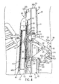
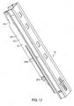
- the fork carriage apparatus lift structure 400 comprises a hydraulic piston/cylinder apparatus 410 including a cylinder 412 and a ram 414, see Fig. 4 .
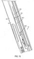
- the cylinder 412 is fixedly coupled to a side section 257D of a third stage weldment rear plate 257 via first and second upper coupling elements 1257E and 1257F and first and second lower coupling elements 2257E and 2257F, see Figs. 3 , 12 , 13 , 14 and 15 .
- the first upper coupling element 1257E is welded to the side section 257D of the third stage weldment rear plate 257, see Figs. 3 , 12 and 13 .
- the second upper coupling element 1257F is welded to the cylinder 412, see Figs.
- the first upper coupling element 1257E and the second upper coupling element 1257F are bolted together via bolts 3257A, see Figs. 14 and 15 .
- the first lower coupling element 2257E is welded to the side section 257D of the third stage weldment rear plate 257, see Figs. 12 , 13 and 15 .
- the second lower coupling element 2257F is welded to the cylinder 412, see Fig. 15 .
- the first lower coupling element 2257E and the second lower coupling element 2257F are joined via pin 3257B, see Fig. 15 .
- the cylinder 412 is mounted to a rear portion 1257D of the side section 257D near an intersection 257F of the side section 257D and a back section 257G of the rear plate 257, see Figs. 3 and 13 .
- First and second pulleys 420 and 422 are coupled to an upper end of the ram 414, see Fig. 4 .
- a lift chain 440 extends over the first pulley 420 and is coupled at a first end 440A to the cylinder 412 via chain anchors and a bracket 441 welded to the cylinder 412 and at its second end 440B to the mast carriage assembly 330, see Fig. 4 .
- Vertical movement of the ram 414 effects vertical movement of the entire fork carriage apparatus 300 relative to the third stage weldment 250.
- Supply and return hydraulic hoses 430 extend over the second pulley 422 or a separate pulley, see Fig. 4 .
- the hydraulic hoses 430 define hydraulic fluid supply and return paths for the fork carriage apparatus 300.
- One or more electrical cables 431 may also extend over the second pulley 422, see Figs. 4 and 14 .
- the one or more electrical cables 431 may control the operation of one or more electronically controlled valves forming part of
- a hydraulic hose 600 extends over a first pulley 1240 coupled to a rear plate 247 of the second stage weldment 240, see Fig. 14 (the third stage weldment 250 is not illustrated in Fig. 14 ).
- the hose 600 is coupled at a first end 600A to a hydraulic supply source (not shown) on the vehicle power unit 102 and to a base of the cylinder 412 of the fork carriage apparatus lift structure 400, see Fig. 14 .
- First and second hydraulic supply and return hoses 610 extend over a second pulley 1242 coupled to the rear plate 247 of the second stage weldment 240, see Fig. 14 .
- First ends 610A of the hydraulic hoses 610 are coupled to appropriate hydraulic fluid supply and return structure provided on the vehicle power unit 102 and second ends 610B of the hydraulic hoses 610 are coupled to metal lines 620, which, in turn, are coupled to the hydraulic hoses 430 discussed above.
- hydraulic fluid may be conveyed from the hydraulic hoses 430 to a manifold 456.
- the manifold 456 includes solenoid actuated valves (not shown) controlling supply of fluid through hydraulic hoses 432 to a fluid junction 450.
- the fluid junction 450 is coupled to hydraulic fluid supply and return structure 452 extending to the piston/cylinder apparatus 373 coupled to the first arm 352A to effect movement of the ram 376 relative to the cylinder 374.
- Metal lines 454 may extend from the fluid junction 450 around the front side of the third stage weldment 250 to provide hydraulic fluid to the piston/cylinder apparatus 373 on the opposite side of the monomast 200, see Fig. 5 .
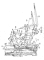
- a fork carriage apparatus 1300 comprises a fork carriage mechanism 1310 to which first and second forks 1402, 1404 are mounted.
- the fork carriage mechanism 1310 is mounted to a reach mechanism 1320 which, in turn, is mounted to a mast carriage assembly 1330.
- the mast carriage assembly 1330 comprises a main unit 1332 including first and second side members 1336A and 1336B, see Figs. 9 and 10 .
- Each of the side members 1336A, 1336B support a plurality of rollers 1334 which are received in the tracks 350 formed in the opposing outer side surfaces 250B and 250C of the third stage weldment 250, see Fig. 3 .
- the main unit 1332 further comprises first, second, third and fourth vertically spaced apart and horizontally extending carriage frame members 1332A, 1332B, 1332C and 1332D extending across the front side FS of the monomast 200, see Figs. 10 and 11 .
- the carriage frame members 1332A, 1332B, 1332C, 1332D are rigidly attached to the side members 1336A and 1336B.
- the reach mechanism 1320 comprises a pantograph or scissors structure having first and second inner arms 1342A and 1342B, and first and second outer arms 1352A and 1352B, see Figs. 9 and 10 .
- the first and second inner arms 1342A and 1342B include first ends 1344A and 1344B (only the first end 1344A is shown in Figs. 9-11 ) directly coupled to the side members 1336A and 1336B of the mast carriage assembly 1330, and second ends 1346A and 1346B pivotally coupled to the fork carriage mechanism 1310.
- Each of the first ends 1344A and 1344B (1344B not shown) includes a roller 1368.
- the rollers 1368 are received in vertically extending tracks 1370 formed in the outer sides of the side members 1336A and 1336B.
- the rollers 1368 engaged within the tracks 1370 form a sliding coupling between the first ends 1344A and 1344B (1344B not shown) of the inner arms 1342A and 1342B and the side members 1336A and 1336B.
- the first and second outer arms 1352A and 1352B include first ends 1354A and 1354B directly coupled to the side members 1336A and 1336B of the mast carriage assembly 1330, and second ends 1356A and 1356B pivotally coupled to the fork carriage mechanism 1310, see Fig. 9 .
- Each of the side members 1336A and 1336B includes a pivot location 1372 where the first ends 1354A and 1354B of the first and second outer arms 1352A and 1352B are coupled to the side members 1336A and 1336B (only pivot connection 1372 to side member 1336A is shown), see Figs. 9 and 10 .
- the first and second inner arms 1342A and 1342B are coupled to the first and second outer arms 1352A and 1352B at pivot connections 1358, see Figs. 9 and 10 .
- a hydraulic piston/cylinder apparatus 1373 is provided for effecting movement of the reach mechanism 1320.
- the piston/cylinder apparatus 1373 comprises a cylinder 1374 extending from each of the side members 1336A and 1336B and including a ram 1376 extending to a coupling tab 1378 provided on each of the first and second outer arms 1352A and 1352B (only piston/cylinder apparatus 1373 connected to outer arm 1352A shown), see Figs. 9 and 10 .
- Movement of the rams 1376 out of the cylinders 1374 effects pivotal movement of the outer arms 1352A and 1352B outwardly from the side members 1336A and 1336B to move the fork carriage mechanism 1310 in a longitudinal direction, as designated by arrow LD in Fig. 10 , to an extended position, see Figs. 9 and 10 .
- Movement of the rams 1376 into the cylinders 1374 effects movement of the fork carriage mechanism 1310 to a retracted position locating the fork carriage mechanism 1310 adjacent to the monomast 200, see Fig. 11 .
- the piston/cylinder apparatus 1373 may be coupled to the first and second inner arms 1342A, 1342B instead of the first and second outer arms 1352A, 1352B.
- the fork carriage mechanism 1310 generally comprises a pair of vertical plates 1380A and 1380B and first, second and third vertically spaced apart fork frame members 1382A, 1382B and 1382C attached to the vertical plates 1380A and 1380B, see Figs. 10 and 11 .
- the second ends 1346A and 1346B of the first and second inner arms 1342A and 1342B are attached to the vertical plates 1380A and 1380B at connection locations 1386, and the second ends 1356A and 1356B of the first and second outer arms 1352A and 1352B are attached to the vertical plates 1380A and 1380B at connection locations (not shown), see Figs. 9 and 10 .
- the forks 1402 and 1404 are supported on the second fork frame member 1382B via a side shift structure 1384 forming part of the carriage frame mechanism 1310.
- the side shift structure 1384 comprises a conventional hydraulically actuated side shift mechanism including a hydraulic piston/cylinder 1396 that effects movement of the forks 1402 and 1404 toward or away from each other or in unison side-to-side along a transverse axis 1392, see Figs. 10 and 11 .
- a tilt structure 1390 which in the illustrated embodiment comprises a single hydraulic piston/cylinder 1394 supported on the vertical plate 1380A for effecting tilting movement of the forks 1402 and 1404 about the transverse axis 1392, see Figs. 9 and 10 .
- a cross member structure 1360 extends between the first and second inner arms 1342A and 1342B and comprises in the illustrated embodiment first, second, third and fourth laterally extending cross members 1362A, 1362B, 1362C and 1362D, see Figs. 9 and 11 .
- the lateral edges or ends of the cross members 1362A, 1362B, 1362C and 1362D are preferably attached at or adjacent to front edges 1364A and 1364B of the inner arms 1342A and 1342B, see Figs. 9 and 10 .
- the cross members 1362A, 1362B, 1362C and 1362D are generally aligned in a common cross member plane P' 300 , see Fig.
- the cross member structure 1360 together with the inner arms 1342A and 1342B define an inner arm weldment 1366, and the area within the inner arm weldment 1366, i.e., behind the cross member structure 1360, comprises an open pocket OP' for receiving the mast carriage assembly 1330 and the monomast 200 during retracting movement of the reach mechanism 1320, see Figs. 9 and 10 .
- the first, second and third cross members 1362A, 1362B and 1362C have a rectangular tubular cross section and the fourth cross member 1362D has a rectangular solid or plate-like cross section, see Fig. 11 .
- the cross members 1362A, 1362B, 1362C and 1362D of the inner arm weldment 1366 and one or more of the carriage frame members 1332A, 1332B, 1332C, 1332D of the mast carriage assembly 1320 are preferably located in a first common vertical plane P' 302 extending substantially parallel to the front side FS of the monomast 200, see Fig. 11 .
- the carriage frame members 1332A, 1332B, 1332C, 1332D are positioned such that they are located in vertically spaced relation to the cross members 1362A, 1362B, 1362C and 1362D, and the cross members 1362A, 1362B, 1362C and 1362D may be in at least partially nested relation between the carriage frame members 1332A, 1332B, 1332C, 1332D, when the fork carriage mechanism 1310 is in the retracted position.
- the fork frame members 1382A, 1382B and 1382C are preferably located in vertically spaced relation to the cross members 1362A, 1362B, 1362C and 1362D.
- At least one of the fork frame members 1382A is formed with a rectangular cross section elongated in the vertical direction, providing sufficient structural strength to the fork carriage mechanism 1310 without overlapping a second common vertical plane P' 304 passing through one or more of the cross members 1362A, 1362B, 1362C and 1362D, substantially parallel to the front side FS of the monomast 200, when the fork carriage mechanism 1310 is in the retracted position, see Fig. 11 .
- the arrangement of the cross members 1362A, 1362B, 1362C and 1362D in vertically spaced relation to the carriage frame members 1332A, 1332B, 1332C, 1332D and the fork frame members 1382A, 1382B and 1382C facilitates close positioning of the cross member structure 1360 to the front of the monomast 200 and close positioning of the fork carriage mechanism 1310 to the inner arm weldment 1366, to minimize the overall longitudinal length of the fork carriage apparatus 1300 in the longitudinal direction LD, and hence the overall longitudinal length of the truck 100 in the longitudinal direction LD, when the fork carriage mechanism 1310 is in the retracted position, see Fig. 11 .
- a manifold 1456 is supported on the side member 1336A for receiving hydraulic fluid conveyed from hydraulic hoses 1430. Hydraulic fluid may be supplied to the hydraulic hoses 1430 by structure similar to that illustrated in the first embodiment described herein.
- the manifold 1456 includes solenoid actuated valves (not shown) for controlling supply of fluid through hydraulic hoses 1432 to a fluid junction 1450.
- the fluid junction 1450 is coupled to hydraulic fluid supply and return hoses 1452 extending to the piston/cylinder apparatus 1373 to effect movement of the ram 1376 relative to the cylinder 1374, see Fig. 10 .
- Metal lines 1454 may extend from the fluid junction 1450 around the front side of the third stage weldment 250 to provide hydraulic fluid to the piston/cylinder apparatus 1373 on the opposite side of the monomast 200, see Fig. 9 .
- the manifold 1456 controls the supply of hydraulic fluid via hydraulic hoses (not shown) to the piston/cylinder 1396 for effecting movement of the side shift structure 1380, and supplies hydraulic fluid via hydraulic hoses (not shown) to the piston/cylinder 1394 for effecting movement of the tilt structure 1390.
Claims (13)
- Véhicule de manutention de matériaux comprenant :un bloc d'alimentation du véhicule (102) ;un monomât (200) couplé audit bloc d'alimentation du véhicule ; etun appareil de tablier porte-fourche (300 ; 1300) supporté sur ledit monomât ;ledit appareil de tablier porte-fourche comprenant :un ensemble de tablier à mât (330 ; 1330) couplé de façon mobile audit monomât ;un mécanisme de tablier porte-fourche (310 ; 1310) sur lequel sont montées les fourches (402, 404 ; 1402, 1404) ; etun mécanisme de rétraction (320 ; 1320) couplé audit ensemble de tablier à mât et audit mécanisme de tablier porte-fourche pour effectuer un mouvement dudit mécanisme de tablier porte-fourche entre une position déployée et une position repliée,caractérisé en ce que ledit ensemble de tablier à mât comprend au moins un élément de châssis de tablier (332A, 332B, 332C, 332D ; 1332A, 1332B, 1332C, 1332D) s'étendant latéralement à travers un côté avant dudit monomât, et le mécanisme de rétraction comprend au moins une traverse s'étendant latéralement (362A, 362B, 362C, 362D ; 1362A, 1362B, 1362C, 1362D) qui est située en relation espacée verticalement par rapport audit élément de châssis de tablier lorsque ledit mécanisme de tablier porte-fourche est dans ladite position repliée.
- Véhicule de manutention de matériaux selon la revendication 1, dans lequel ledit au moins un élément de châssis de tablier (332A, 332B, 332C, 332D ; 1332A, 1332B, 1332C, 1332D) comprend des premier et second éléments de châssis de tablier s'étendant latéralement à travers ledit côté avant dudit monomât (200), et ladite traverse (362A, 362B, 362C, 362D ; 1362A, 1362B, 1362C, 1362D) est située entre lesdits premier et second éléments de châssis de tablier lorsque ledit mécanisme de tablier porte-fourche (310 ; 1310) est dans ladite position repliée.
- Véhicule de manutention de matériaux selon la revendication 1, dans lequel ledit élément de châssis de tablier (332A, 332B, 332C, 332D ; 1332A, 1332B, 1332C, 1332D) et ladite traverse (362A, 362B, 362C, 362D ; 1362A, 1362B, 1362C, 1362D) coupent un plan vertical commun s'étendant devant et généralement parallèle audit monomât (200) lorsque ledit mécanisme de tablier porte-fourche (310 ; 1310) est dans ladite position repliée.
- Véhicule de manutention de matériaux selon la revendication 1, dans lequel ledit mécanisme de rétraction (320 ; 1320) comprend une pluralité de traverses (362A, 362B, 362C, 362D ; 1362A, 1362B, 1362C, 1362D) et ledit élément de châssis de tablier (332A, 332B, 332C, 332D ; 1332A, 1332B, 1332C, 1332D) est situé entre deux desdites traverses lorsque ledit mécanisme de tablier porte-fourche (310 ; 1310) est dans ladite position repliée.
- Véhicule de manutention de matériaux selon la revendication 4, dans lequel ledit mécanisme de tablier porte-fourche (310 ; 1310) comprend au moins un élément de châssis de fourche s'étendant latéralement (382A, 382B, 382C ; 1382A, 1382B, 1382C), et ledit élément de châssis de fourche est situé entre lesdites deux traverses (362A, 362B, 362C, 362D ; 1362A, 1362B, 1362C, 1362D) lorsque ledit mécanisme de tablier porte-fourche est dans ladite position repliée.
- Véhicule de manutention de matériaux selon la revendication 1, dans lequel ledit mécanisme de rétraction (320 ; 1320) comprend une structure en ciseaux comprenant :des premier et second bras internes (342A, 342B ; 1342A, 1342B), chacun desdits premier et second bras internes comprenant une première extrémité (344A, 344B ; 1344A, 1344B) couplée directement audit ensemble de tablier à mât (330 ; 1330) et une seconde extrémité (346A, 346B ; 1346A, 1346B) couplée audit mécanisme de tablier porte-fourche (310 ; 1310) ;des premier et second bras externes (352A, 352B ; 1352A, 1352B), chacun desdits premier et second bras externes comprenant une première extrémité (354A, 354B ; 1354A, 1354B) couplée directement audit ensemble de tablier à mât et une seconde extrémité (356A, 356B ; 1356A, 1356B) couplée audit mécanisme de tablier porte-fourche ; etlesdits premier et second bras internes sont couplés auxdits premier et second bras externes.
- Véhicule de manutention de matériaux selon la revendication 6, dans lequel ladite au moins une traverse (362A, 362B, 362C, 362D ; 1362A, 1362B, 1362C, 1362D) s'étend entre lesdits premier et second bras internes (342A, 342B ; 1342A, 1342B) et comporte des bords latéraux fixés adjacents aux bords avant desdits premier et second bras internes pour définir un ensemble soudé de bras interne (366 ; 1366).
- Véhicule de manutention de matériaux selon la revendication 7, dans lequel ladite au moins une traverse (362A, 362B, 362C, 362D ; 1362A, 1362B, 1362C, 1362D) est généralement alignée avec au moins une autre traverse sur ledit mécanisme de rétraction (320 ; 1320) dans un plan commun s'étendant adjacent à des bords avant desdits premier et second bras internes (342A, 342B ; 1342A, 1342B).
- Véhicule de manutention de matériaux selon la revendication 7, dans lequel ledit mécanisme de tablier porte-fourche (310 ; 1310) comprend au moins un élément de châssis de fourche s'étendant latéralement (382A, 382B, 382C ; 1382A, 1382B, 1382C) et, lorsque ledit mécanisme de tablier porte-fourche est dans ladite position repliée, ledit élément de châssis de fourche et ladite traverse (362A, 362B, 362C, 362D ; 1362A, 1362B, 1362C, 1362D) coupent un plan vertical commun s'étendant devant et généralement parallèle audit monomât (200).
- Véhicule de manutention de matériaux selon la revendication 6, dans lequel ledit ensemble de tablier à mât (330 ; 1330) comprend en outre des premier et second longerons (366A, 366B ; 1366A, 1366B) situés pour un mouvement le long de bords externes dudit monomât (200), et lesdites premières extrémités (344A, 344B, 354A, 354B ; 1344A, 1344B, 1354A, 1354B) desdits bras internes (342A, 342B ; 1342A, 1342B) et externes (352A, 352B ; 1352A, 1352B) sont couplés auxdits premier et second longerons.
- Véhicule de manutention de matériaux selon la revendication 10, dans lequel lesdites premières extrémités (344A, 344B ; 1344A, 1344B) desdits premier et second bras internes (342A, 342B ; 1342A, 1342B) sont supportées pour un mouvement vertical le long de rails verticaux dans lesdits premier et second longerons (366A, 366B ; 1366A, 1366B), et lesdites premières extrémités (354A, 354B ; 1354A, 1354B) desdits premier et second bras externes (352A, 352B ; 1352A, 1352B) sont couplées auxdits premier et second longerons au niveau d'emplacements de pivot respectifs (372 ; 1372).
- Véhicule de manutention de matériaux selon la revendication 10 ou 11, dans lequel lesdits bras internes (342A, 342B ; 1342A, 1342B) et externes (352A, 352B ; 1352A, 1352B) s'étendent sensiblement verticalement et sont en relation chevauchante sur lesdits premier et second longerons (366A, 366B ; 1366A, 1366B) lorsque ledit mécanisme de tablier porte-fourche (310 ; 1310) est dans ladite position repliée.
- Véhicule de manutention de matériaux selon la revendication 10 ou 11, dans lequel ledit appareil de tablier porte-fourche (300 ; 1300) comprend en outre un appareil à piston/cylindre (373 ; 1373) couplé entre au moins l'un desdits longerons (366A, 366B ; 1366A, 1366B) et un bras respectif desdits bras externes (352A, 352B ; 1352A, 1352B) ou internes (342A, 342B ; 1342A, 1342B) pour actionner ledit mécanisme de rétraction (320 ; 1320) entre lesdites positions déployée et repliée.
Applications Claiming Priority (3)
| Application Number | Priority Date | Filing Date | Title |
|---|---|---|---|
| US9674908P | 2008-09-12 | 2008-09-12 | |
| US9674508P | 2008-09-12 | 2008-09-12 | |
| PCT/US2009/056543 WO2010030803A1 (fr) | 2008-09-12 | 2009-09-10 | Appareil de chariot à fourches pour véhicule de manutention de matériaux |
Publications (2)
| Publication Number | Publication Date |
|---|---|
| EP2342155A1 EP2342155A1 (fr) | 2011-07-13 |
| EP2342155B1 true EP2342155B1 (fr) | 2015-07-22 |
Family
ID=41376322
Family Applications (2)
| Application Number | Title | Priority Date | Filing Date |
|---|---|---|---|
| EP09792423.7A Active EP2331448B1 (fr) | 2008-09-12 | 2009-09-10 | Mât unique pour véhicule de manutention de matériaux |
| EP09792427.8A Active EP2342155B1 (fr) | 2008-09-12 | 2009-09-10 | Appareil de chariot à fourches pour véhicule de manutention de matériaux |
Family Applications Before (1)
| Application Number | Title | Priority Date | Filing Date |
|---|---|---|---|
| EP09792423.7A Active EP2331448B1 (fr) | 2008-09-12 | 2009-09-10 | Mât unique pour véhicule de manutention de matériaux |
Country Status (10)
| Country | Link |
|---|---|
| US (3) | US8714311B2 (fr) |
| EP (2) | EP2331448B1 (fr) |
| KR (2) | KR101604240B1 (fr) |
| CN (2) | CN102186763B (fr) |
| AU (2) | AU2009291737B2 (fr) |
| BR (2) | BRPI0918537A2 (fr) |
| CA (2) | CA2736384C (fr) |
| ES (1) | ES2548246T3 (fr) |
| MX (3) | MX2011002734A (fr) |
| WO (2) | WO2010030797A1 (fr) |
Cited By (1)
| Publication number | Priority date | Publication date | Assignee | Title |
|---|---|---|---|---|
| CN105540495A (zh) * | 2016-02-19 | 2016-05-04 | 龙工(上海)机械制造有限公司 | 一种剪叉式伸缩臂装载机 |
Families Citing this family (35)
| Publication number | Priority date | Publication date | Assignee | Title |
|---|---|---|---|---|
| WO2010030797A1 (fr) | 2008-09-12 | 2010-03-18 | Crown Equipment Corporation | Mât unique pour véhicule de manutention de matériaux |
| EP2661409B1 (fr) | 2011-01-04 | 2016-12-28 | Crown Equipment Corporation | Véhicule de manipulation de matériels possédant un collecteur située sur une unité d'alimentation pour maintenir la pression de fluide au niveau d'un orifice de sortie à une pression commandée correspondant à une pression de fonctionnement de dispositif auxiliaire |
| RU2016136705A (ru) | 2011-02-16 | 2018-12-11 | Краун Эквайпмент Корпорейшн | Погрузочно-разгрузочное транспортное средство, рассчитывающее скорость подвижного узла по скорости двигателя механизма подъёма |
| CN103875021B (zh) | 2011-10-19 | 2017-07-11 | 克朗设备公司 | 识别并选择图像场景中可能对应于托盘的对象 |
| JP2014530796A (ja) * | 2011-10-21 | 2014-11-20 | モボット インダストリーズリミテッド | 昇降装置 |
| US9309902B2 (en) | 2012-01-13 | 2016-04-12 | Crown Equipment Corporation | Warm up cycle for a materials handling vehicle |
| CN102556901A (zh) * | 2012-01-15 | 2012-07-11 | 浙江中力机械有限公司 | 叉车门架 |
| CN102795575A (zh) * | 2012-09-10 | 2012-11-28 | 朱红蔚 | 随车式装卸货作业设备的剪叉式前移装置 |
| DE102013201655A1 (de) * | 2013-01-31 | 2014-07-31 | Jungheinrich Aktiengesellschaft | Hubzylinder mit einer Umlenkrollenvorrichtung für ein Flurförderzeug |
| CN105189330A (zh) * | 2013-02-04 | 2015-12-23 | 克朗设备公司 | 用于物料搬运车辆的具有偏移枢转点的前伸组件 |
| US9206024B2 (en) | 2013-03-15 | 2015-12-08 | The Raymond Corporation | Systems and methods for sensor controlled reach carriage |
| USD749289S1 (en) | 2014-08-13 | 2016-02-09 | Cascade Corporation | Forklift fork tip |
| CN106573766B (zh) * | 2014-08-19 | 2019-06-18 | 克朗设备公司 | 用于物料搬运车辆的分散式操作指示器系统 |
| US9926178B2 (en) | 2014-08-20 | 2018-03-27 | Crown Equipment Corporation | Actuator in a lift truck |
| CN104355271B (zh) * | 2014-10-23 | 2017-01-25 | 安徽合力股份有限公司 | 一种实现高起升的前移式叉车的起重系统 |
| US10501296B2 (en) * | 2015-06-29 | 2019-12-10 | Palfinger Ag | Linkage system for a forklift truck |
| US10427692B2 (en) | 2015-07-28 | 2019-10-01 | Crown Equipment Corporation | Vehicle control module with signal switchboard and input tables |
| BR112018001920A2 (pt) | 2015-08-14 | 2018-09-25 | Crown Equip Corp | método e sistema de controle de veículo |
| US10294089B2 (en) * | 2015-12-03 | 2019-05-21 | The Raymond Corporation | Systems and methods for a material handling vehicle with a floor suspension |
| US9990535B2 (en) | 2016-04-27 | 2018-06-05 | Crown Equipment Corporation | Pallet detection using units of physical length |
| CA3222202A1 (fr) * | 2016-05-23 | 2017-11-30 | Crown Equipment Corporation | Systemes et procedes d'utilisation d'un vehicule de manutention de materiaux dans un environnement d'entrepot |
| KR20180001290U (ko) | 2016-10-26 | 2018-05-04 | 현대건설기계 주식회사 | 지게차 |
| DE102016120842B4 (de) | 2016-11-02 | 2019-12-19 | Jungheinrich Aktiengesellschaft | Flurförderzeug mit einem Monomast |
| DE102016124506A1 (de) * | 2016-12-15 | 2018-06-21 | Jungheinrich Aktiengesellschaft | Flurförderzeug mit einer Steuereinheit zur Regelung der Bewegung einer Last sowie ein entsprechendes Verfahren |
| MX2019008406A (es) | 2017-01-13 | 2019-09-16 | Crown Equip Corp | Recuperacion de velocidad de traccion con base en dinamica de rueda de giro. |
| US10723382B2 (en) | 2017-01-13 | 2020-07-28 | Crown Equipment Corporation | High speed straight ahead tiller desensitization |
| US10662047B2 (en) | 2017-03-30 | 2020-05-26 | The Raymond Corporation | Extendable mast systems and methods for a material handling vehicle |
| US10961097B1 (en) | 2017-03-31 | 2021-03-30 | Rightline Equipment, Inc. | High visibility push-pull forklift attachment |
| US11274022B2 (en) * | 2018-05-03 | 2022-03-15 | Hyster-Yale Group, Inc. | Pantograph assembly for lift truck |
| USD891022S1 (en) | 2018-07-25 | 2020-07-21 | Zhejiang E-P Equipment Co., Ltd. | Powered Stacker Vehicle |
| TWI743389B (zh) * | 2018-08-30 | 2021-10-21 | 張志峰 | 運輸設備 |
| US11352243B2 (en) | 2018-09-13 | 2022-06-07 | Crown Equipment Corporation | System and method for controlling a maximum vehicle speed for an industrial vehicle based on a calculated load |
| CN109179269A (zh) * | 2018-11-21 | 2019-01-11 | 长沙长泰智能装备有限公司 | 一种重型圆柱型货物堆高agv |
| CN110451432B (zh) * | 2019-08-21 | 2021-02-05 | 广东博智林机器人有限公司 | 一种搬运机器人 |
| CN113788437A (zh) * | 2021-09-14 | 2021-12-14 | 杭州联核科技有限公司 | 一种无人驾驶前移叉车 |
Family Cites Families (72)
| Publication number | Priority date | Publication date | Assignee | Title |
|---|---|---|---|---|
| US2635711A (en) * | 1949-08-27 | 1953-04-21 | Clark Equipment Co | Hand lift truck |
| US2747689A (en) | 1952-08-30 | 1956-05-29 | Elwell Parker Electric Co | Tier lift truck |
| USRE24958E (en) | 1954-09-30 | 1961-03-28 | G ehmann | |
| US2915144A (en) | 1955-10-31 | 1959-12-01 | Hyster Co | Free lift truck |
| US2925888A (en) | 1956-03-28 | 1960-02-23 | Ver Westdeutsche Waggonfab | Lift post especially for lift trucks |
| DE1131146B (de) | 1957-03-11 | 1962-06-07 | Kloeckner Humboldt Deutz Ag | Seitenlader mit einem stirnseitigen, seitlich versetzten Hubmast |
| US2973878A (en) | 1957-06-24 | 1961-03-07 | Raymond Corp | Material handling truck |
| DE1189922B (de) | 1959-12-04 | 1965-03-25 | Linde Eismasch Ag | Hublader mit teleskopischem Zentralmast |
| US3035663A (en) | 1959-12-04 | 1962-05-22 | Linde Eismaschinen Ag | Mast for conveyer vehicles |
| US3095945A (en) | 1959-12-22 | 1963-07-02 | Lift A Loft Corp | Overhead service unit |
| US3082894A (en) * | 1960-06-09 | 1963-03-26 | Raymond Corp | Lift truck reach mechanism |
| US3061045A (en) | 1960-11-21 | 1962-10-30 | Multi Lift Co | Friction-free load hoisting mast |
| GB1031772A (en) * | 1962-04-13 | 1966-06-02 | Lansing Bagnall Ltd | Improvements in or relating to fork and like load-lifting trucks |
| DE1257676B (de) * | 1962-12-06 | 1967-12-28 | Aloysius Thedorus Van Huet | Hublader mit dem Vorschieben des Lasttraegers dienender Schere |
| US3372823A (en) | 1965-10-04 | 1968-03-12 | Raymond Corp | Lift truck mast tilting arrangement |
| DE1456892C3 (de) | 1966-05-06 | 1975-05-28 | Steinbock Gmbh, 8052 Moosburg | Teleskopmast-Hubantrieb für einen Hublader |
| US3534664A (en) * | 1967-09-06 | 1970-10-20 | Eaton Yale & Towne | Lift truck mast and ram assembly |
| US3485323A (en) * | 1967-09-06 | 1969-12-23 | Eaton Yale & Towne | Lift truck mast and ram assembly |
| US3472341A (en) | 1967-12-18 | 1969-10-14 | Crown Controls Corp | Lift truck with telescopic mast |
| US3490633A (en) | 1968-02-01 | 1970-01-20 | Case Co J I | Assembly for laterally shifting and pivoting a mast of a lift truck |
| JPS4833578B1 (fr) | 1969-02-25 | 1973-10-15 | ||
| JPS4833577B1 (fr) * | 1969-09-27 | 1973-10-15 | ||
| JPS4833577A (fr) * | 1971-09-01 | 1973-05-11 | ||
| US3998345A (en) | 1974-04-05 | 1976-12-21 | Missouri Research Laboratories, Inc. | Side loader for fork lift trucks |
| BG27536A3 (en) | 1974-06-26 | 1979-11-12 | Linde Ag,De | Telescopic gieting apparatus for highlifters |
| US3968859A (en) * | 1974-12-23 | 1976-07-13 | Allis-Chalmers Corporation | Multiple hose guide arrangement for a lift truck |
| US3998346A (en) * | 1975-02-03 | 1976-12-21 | The Raymond Corporation | Material handling apparatus |
| US4019786A (en) | 1975-04-30 | 1977-04-26 | Towmotor Corporation | Shielded side thrust roller assembly for lift truck mast units |
| US3972388A (en) | 1975-08-04 | 1976-08-03 | Towmotor Corporation | Lift truck mast assembly with a resilient chain positioner |
| US3987870A (en) | 1975-11-03 | 1976-10-26 | Towmotor Corporation | Mast assembly |
| US4051970A (en) | 1975-11-07 | 1977-10-04 | K-D Manufacturing Company | Lift truck load handling mast |
| US4084715A (en) | 1976-02-23 | 1978-04-18 | Caterpillar Tractor Co. | Lift truck with means to pivot mast and the fork carriage thereon |
| JPS52123066A (en) * | 1976-04-07 | 1977-10-15 | Toyo Umpanki Co Ltd | Fully free three-stage mast |
| JPS5410783A (en) | 1977-06-27 | 1979-01-26 | Ngk Spark Plug Co | Glow plug for temperature detector |
| US4258825A (en) * | 1978-05-18 | 1981-03-31 | Collins Pat L | Powered manlift cart |
| US4355703A (en) | 1979-03-08 | 1982-10-26 | Clark Equipment Company | Upright for lift truck |
| US4354579A (en) | 1980-06-30 | 1982-10-19 | Low Leonard J | Apparatus for guiding lift truck mast segments |
| US4543031A (en) | 1983-04-22 | 1985-09-24 | Crown Controls Corporation | Apparatus for sideshift carriage control |
| US4552250A (en) * | 1983-04-22 | 1985-11-12 | Crown Controls Corporation | Lift truck |
| JPS606598A (ja) | 1983-06-27 | 1985-01-14 | 小松フオ−クリフト株式会社 | マスト装置 |
| SE460116B (sv) | 1985-02-01 | 1989-09-11 | Jungheinrich Kg | Transportdon, i synnerhet staplingsfordon |
| GB2199302A (en) | 1986-12-22 | 1988-07-06 | Carelift Equipment Limited | Telescopic mast assembly |
| JPH0833577B2 (ja) | 1988-04-20 | 1996-03-29 | 富士写真フイルム株式会社 | 複写機の自動露光装置 |
| US5046585A (en) * | 1989-02-23 | 1991-09-10 | Kabushiki Kaisha Toyoda Jidoshokki Seisakusho | Upright assembly for fork lift truck |
| US4944368A (en) | 1989-05-25 | 1990-07-31 | Duderstadt J Christopher | Lift truck having improved single mast and bearing wheel assembly |
| US5022496A (en) | 1989-12-05 | 1991-06-11 | Crown Equipment Corporation | Slowdown during staging of a turret stockpicker |
| JPH079909Y2 (ja) | 1990-04-25 | 1995-03-08 | 東洋運搬機株式会社 | フォークリフト |
| JPH079909A (ja) | 1993-06-24 | 1995-01-13 | Sekisui Chem Co Ltd | 車両用ロッジ |
| US5515945A (en) | 1994-04-18 | 1996-05-14 | Genie Industries, Inc. | Multi-stage mast assembly for portable lifts |
| US5645142A (en) * | 1994-04-18 | 1997-07-08 | Genie Industries | Wedge braking system for multi-stage lifts |
| JP2788193B2 (ja) * | 1994-07-25 | 1998-08-20 | リンナイ株式会社 | 焼物調理器 |
| US5657834A (en) | 1994-08-30 | 1997-08-19 | Crown Equipment Corporation | Mast staging cushion apparatus |
| US5586620A (en) | 1995-05-12 | 1996-12-24 | Crown Equipment Corporation | Remote viewing apparatus for fork lift trucks |
| DE29514676U1 (de) * | 1995-09-13 | 1997-01-30 | Jungheinrich Ag | Stapler |
| US5803204A (en) * | 1995-10-23 | 1998-09-08 | Upright, Inc. | Personnel lift with clamshell cage assembly |
| KR0111588Y1 (en) | 1995-12-30 | 1997-12-22 | Daewoo Heavy Ind Co Ltd | Structure of establishment of attachment oil pressure in fork lift truck |
| US5850892A (en) * | 1997-01-23 | 1998-12-22 | Genie Industries, Inc. | Personnel lift with adjustable shim wear blocks |
| KR100523158B1 (ko) * | 1997-09-30 | 2005-10-24 | 크라운 이큅먼트 코포레이션 | 생산성 패키지 |
| NL1007308C2 (nl) * | 1997-10-17 | 1999-04-20 | Cangaru Forklift B V | Heftruck met excentrische hefmast. |
| EP1046609B2 (fr) | 1999-04-21 | 2017-07-19 | Crown Gabelstapler GmbH | Chariot élévateur à mât déplaçable |
| US6757958B1 (en) | 2000-05-11 | 2004-07-06 | Jlg Omniquip, Inc. | Load handler with modular frame assembly |
| US20020100644A1 (en) * | 2001-01-31 | 2002-08-01 | Stringer Matthew D. | Mast assembly |
| GB2375341B (en) | 2001-05-11 | 2004-09-08 | Lansing Linde Ltd | load handling device for an industrial truck |
| CN2510474Y (zh) | 2001-09-15 | 2002-09-11 | 安徽合力股份有限公司 | 胶管滑轮式叉车属具供油机构 |
| US6533076B1 (en) | 2002-02-06 | 2003-03-18 | Crown Equipment Corporation | Materials handling vehicle mast height sensor |
| DE10225080C1 (de) * | 2002-06-05 | 2003-12-04 | Yale Ind Products Gmbh | Flurförderfahrzeug |
| US7096999B2 (en) * | 2003-08-05 | 2006-08-29 | The Raymond Corporation | Mast construction for a lift truck |
| US7344000B2 (en) | 2004-09-23 | 2008-03-18 | Crown Equipment Corporation | Electronically controlled valve for a materials handling vehicle |
| US20060070816A1 (en) | 2004-09-30 | 2006-04-06 | Schroder Werner G | Lift truck with central mast |
| JP4833577B2 (ja) | 2005-04-05 | 2011-12-07 | 古河電気工業株式会社 | 内面溝付管の製造装置及び製造方法 |
| US20070080024A1 (en) * | 2005-09-27 | 2007-04-12 | David Langenkamp | Pulley assembly for a materials handling vehicle mast assembly |
| WO2010030797A1 (fr) | 2008-09-12 | 2010-03-18 | Crown Equipment Corporation | Mât unique pour véhicule de manutention de matériaux |
-
2009
- 2009-09-10 WO PCT/US2009/056534 patent/WO2010030797A1/fr active Application Filing
- 2009-09-10 CA CA2736384A patent/CA2736384C/fr active Active
- 2009-09-10 BR BRPI0918537A patent/BRPI0918537A2/pt not_active Application Discontinuation
- 2009-09-10 WO PCT/US2009/056543 patent/WO2010030803A1/fr active Application Filing
- 2009-09-10 ES ES09792427.8T patent/ES2548246T3/es active Active
- 2009-09-10 KR KR1020117008244A patent/KR101604240B1/ko active IP Right Grant
- 2009-09-10 BR BRPI0918161A patent/BRPI0918161A2/pt not_active Application Discontinuation
- 2009-09-10 MX MX2011002734A patent/MX2011002734A/es active IP Right Grant
- 2009-09-10 MX MX2011002736A patent/MX341580B/es active IP Right Grant
- 2009-09-10 AU AU2009291737A patent/AU2009291737B2/en active Active
- 2009-09-10 AU AU2009291731A patent/AU2009291731B2/en active Active
- 2009-09-10 KR KR1020117007916A patent/KR101604239B1/ko active IP Right Grant
- 2009-09-10 EP EP09792423.7A patent/EP2331448B1/fr active Active
- 2009-09-10 US US12/557,116 patent/US8714311B2/en active Active
- 2009-09-10 CN CN2009801410636A patent/CN102186763B/zh active Active
- 2009-09-10 US US12/557,146 patent/US8851825B2/en active Active
- 2009-09-10 EP EP09792427.8A patent/EP2342155B1/fr active Active
- 2009-09-10 CN CN200980135436.9A patent/CN102149624B/zh active Active
- 2009-09-10 CA CA2736383A patent/CA2736383C/fr active Active
-
2011
- 2011-03-11 MX MX2021001621A patent/MX2021001621A/es unknown
-
2014
- 2014-07-15 US US14/331,650 patent/US10144626B2/en active Active
Cited By (1)
| Publication number | Priority date | Publication date | Assignee | Title |
|---|---|---|---|---|
| CN105540495A (zh) * | 2016-02-19 | 2016-05-04 | 龙工(上海)机械制造有限公司 | 一种剪叉式伸缩臂装载机 |
Also Published As
Similar Documents
| Publication | Publication Date | Title |
|---|---|---|
| EP2342155B1 (fr) | Appareil de chariot à fourches pour véhicule de manutention de matériaux | |
| US10023448B2 (en) | Lift truck with mast | |
| US6571913B2 (en) | Multipurpose machine | |
| AU2006315241B2 (en) | A materials handling vehicle with a manifold apparatus including a valve structure mounted on the mast assembly | |
| US3490633A (en) | Assembly for laterally shifting and pivoting a mast of a lift truck | |
| EP0545877B1 (fr) | Véhicule pour stocker des charges | |
| US6439827B1 (en) | Load handling vehicle | |
| GB2327077A (en) | Compact load handling vehicle | |
| US20070068740A1 (en) | Fluid supply hose coupling structure for a materials handling vehicle | |
| JP2001247299A (ja) | フォークリフト |
Legal Events
| Date | Code | Title | Description |
|---|---|---|---|
| PUAI | Public reference made under article 153(3) epc to a published international application that has entered the european phase |
Free format text: ORIGINAL CODE: 0009012 |
|
| 17P | Request for examination filed |
Effective date: 20110412 |
|
| AK | Designated contracting states |
Kind code of ref document: A1 Designated state(s): AT BE BG CH CY CZ DE DK EE ES FI FR GB GR HR HU IE IS IT LI LT LU LV MC MK MT NL NO PL PT RO SE SI SK SM TR |
|
| AX | Request for extension of the european patent |
Extension state: AL BA RS |
|
| DAX | Request for extension of the european patent (deleted) | ||
| 17Q | First examination report despatched |
Effective date: 20131107 |
|
| GRAP | Despatch of communication of intention to grant a patent |
Free format text: ORIGINAL CODE: EPIDOSNIGR1 |
|
| INTG | Intention to grant announced |
Effective date: 20150225 |
|
| GRAS | Grant fee paid |
Free format text: ORIGINAL CODE: EPIDOSNIGR3 |
|
| GRAA | (expected) grant |
Free format text: ORIGINAL CODE: 0009210 |
|
| AK | Designated contracting states |
Kind code of ref document: B1 Designated state(s): AT BE BG CH CY CZ DE DK EE ES FI FR GB GR HR HU IE IS IT LI LT LU LV MC MK MT NL NO PL PT RO SE SI SK SM TR |
|
| REG | Reference to a national code |
Ref country code: GB Ref legal event code: FG4D |
|
| REG | Reference to a national code |
Ref country code: CH Ref legal event code: EP |
|
| REG | Reference to a national code |
Ref country code: IE Ref legal event code: FG4D |
|
| REG | Reference to a national code |
Ref country code: AT Ref legal event code: REF Ref document number: 737767 Country of ref document: AT Kind code of ref document: T Effective date: 20150815 |
|
| REG | Reference to a national code |
Ref country code: DE Ref legal event code: R096 Ref document number: 602009032398 Country of ref document: DE |
|
| REG | Reference to a national code |
Ref country code: ES Ref legal event code: FG2A Ref document number: 2548246 Country of ref document: ES Kind code of ref document: T3 Effective date: 20151015 |
|
| REG | Reference to a national code |
Ref country code: NL Ref legal event code: FP |
|
| REG | Reference to a national code |
Ref country code: AT Ref legal event code: MK05 Ref document number: 737767 Country of ref document: AT Kind code of ref document: T Effective date: 20150722 |
|
| REG | Reference to a national code |
Ref country code: LT Ref legal event code: MG4D |
|
| REG | Reference to a national code |
Ref country code: FR Ref legal event code: PLFP Year of fee payment: 7 |
|
| PG25 | Lapsed in a contracting state [announced via postgrant information from national office to epo] |
Ref country code: LT Free format text: LAPSE BECAUSE OF FAILURE TO SUBMIT A TRANSLATION OF THE DESCRIPTION OR TO PAY THE FEE WITHIN THE PRESCRIBED TIME-LIMIT Effective date: 20150722 Ref country code: LV Free format text: LAPSE BECAUSE OF FAILURE TO SUBMIT A TRANSLATION OF THE DESCRIPTION OR TO PAY THE FEE WITHIN THE PRESCRIBED TIME-LIMIT Effective date: 20150722 Ref country code: FI Free format text: LAPSE BECAUSE OF FAILURE TO SUBMIT A TRANSLATION OF THE DESCRIPTION OR TO PAY THE FEE WITHIN THE PRESCRIBED TIME-LIMIT Effective date: 20150722 Ref country code: NO Free format text: LAPSE BECAUSE OF FAILURE TO SUBMIT A TRANSLATION OF THE DESCRIPTION OR TO PAY THE FEE WITHIN THE PRESCRIBED TIME-LIMIT Effective date: 20151022 Ref country code: GR Free format text: LAPSE BECAUSE OF FAILURE TO SUBMIT A TRANSLATION OF THE DESCRIPTION OR TO PAY THE FEE WITHIN THE PRESCRIBED TIME-LIMIT Effective date: 20151023 |
|
| PG25 | Lapsed in a contracting state [announced via postgrant information from national office to epo] |
Ref country code: AT Free format text: LAPSE BECAUSE OF FAILURE TO SUBMIT A TRANSLATION OF THE DESCRIPTION OR TO PAY THE FEE WITHIN THE PRESCRIBED TIME-LIMIT Effective date: 20150722 Ref country code: IS Free format text: LAPSE BECAUSE OF FAILURE TO SUBMIT A TRANSLATION OF THE DESCRIPTION OR TO PAY THE FEE WITHIN THE PRESCRIBED TIME-LIMIT Effective date: 20151122 Ref country code: SE Free format text: LAPSE BECAUSE OF FAILURE TO SUBMIT A TRANSLATION OF THE DESCRIPTION OR TO PAY THE FEE WITHIN THE PRESCRIBED TIME-LIMIT Effective date: 20150722 Ref country code: PT Free format text: LAPSE BECAUSE OF FAILURE TO SUBMIT A TRANSLATION OF THE DESCRIPTION OR TO PAY THE FEE WITHIN THE PRESCRIBED TIME-LIMIT Effective date: 20151123 Ref country code: PL Free format text: LAPSE BECAUSE OF FAILURE TO SUBMIT A TRANSLATION OF THE DESCRIPTION OR TO PAY THE FEE WITHIN THE PRESCRIBED TIME-LIMIT Effective date: 20150722 Ref country code: HR Free format text: LAPSE BECAUSE OF FAILURE TO SUBMIT A TRANSLATION OF THE DESCRIPTION OR TO PAY THE FEE WITHIN THE PRESCRIBED TIME-LIMIT Effective date: 20150722 |
|
| REG | Reference to a national code |
Ref country code: DE Ref legal event code: R097 Ref document number: 602009032398 Country of ref document: DE |
|
| PG25 | Lapsed in a contracting state [announced via postgrant information from national office to epo] |
Ref country code: EE Free format text: LAPSE BECAUSE OF FAILURE TO SUBMIT A TRANSLATION OF THE DESCRIPTION OR TO PAY THE FEE WITHIN THE PRESCRIBED TIME-LIMIT Effective date: 20150722 Ref country code: MC Free format text: LAPSE BECAUSE OF FAILURE TO SUBMIT A TRANSLATION OF THE DESCRIPTION OR TO PAY THE FEE WITHIN THE PRESCRIBED TIME-LIMIT Effective date: 20150722 Ref country code: DK Free format text: LAPSE BECAUSE OF FAILURE TO SUBMIT A TRANSLATION OF THE DESCRIPTION OR TO PAY THE FEE WITHIN THE PRESCRIBED TIME-LIMIT Effective date: 20150722 Ref country code: SK Free format text: LAPSE BECAUSE OF FAILURE TO SUBMIT A TRANSLATION OF THE DESCRIPTION OR TO PAY THE FEE WITHIN THE PRESCRIBED TIME-LIMIT Effective date: 20150722 Ref country code: CZ Free format text: LAPSE BECAUSE OF FAILURE TO SUBMIT A TRANSLATION OF THE DESCRIPTION OR TO PAY THE FEE WITHIN THE PRESCRIBED TIME-LIMIT Effective date: 20150722 Ref country code: LU Free format text: LAPSE BECAUSE OF FAILURE TO SUBMIT A TRANSLATION OF THE DESCRIPTION OR TO PAY THE FEE WITHIN THE PRESCRIBED TIME-LIMIT Effective date: 20150910 |
|
| REG | Reference to a national code |
Ref country code: CH Ref legal event code: PL |
|
| PLBE | No opposition filed within time limit |
Free format text: ORIGINAL CODE: 0009261 |
|
| STAA | Information on the status of an ep patent application or granted ep patent |
Free format text: STATUS: NO OPPOSITION FILED WITHIN TIME LIMIT |
|
| REG | Reference to a national code |
Ref country code: DE Ref legal event code: R082 Ref document number: 602009032398 Country of ref document: DE Representative=s name: HERNANDEZ, YORCK, DIPL.-ING., DE |
|
| PG25 | Lapsed in a contracting state [announced via postgrant information from national office to epo] |
Ref country code: RO Free format text: LAPSE BECAUSE OF FAILURE TO SUBMIT A TRANSLATION OF THE DESCRIPTION OR TO PAY THE FEE WITHIN THE PRESCRIBED TIME-LIMIT Effective date: 20150722 |
|
| 26N | No opposition filed |
Effective date: 20160425 |
|
| REG | Reference to a national code |
Ref country code: IE Ref legal event code: MM4A |
|
| PG25 | Lapsed in a contracting state [announced via postgrant information from national office to epo] |
Ref country code: CH Free format text: LAPSE BECAUSE OF NON-PAYMENT OF DUE FEES Effective date: 20150930 Ref country code: LI Free format text: LAPSE BECAUSE OF NON-PAYMENT OF DUE FEES Effective date: 20150930 Ref country code: IE Free format text: LAPSE BECAUSE OF NON-PAYMENT OF DUE FEES Effective date: 20150910 |
|
| PG25 | Lapsed in a contracting state [announced via postgrant information from national office to epo] |
Ref country code: SI Free format text: LAPSE BECAUSE OF FAILURE TO SUBMIT A TRANSLATION OF THE DESCRIPTION OR TO PAY THE FEE WITHIN THE PRESCRIBED TIME-LIMIT Effective date: 20150722 |
|
| REG | Reference to a national code |
Ref country code: FR Ref legal event code: PLFP Year of fee payment: 8 |
|
| PG25 | Lapsed in a contracting state [announced via postgrant information from national office to epo] |
Ref country code: MT Free format text: LAPSE BECAUSE OF FAILURE TO SUBMIT A TRANSLATION OF THE DESCRIPTION OR TO PAY THE FEE WITHIN THE PRESCRIBED TIME-LIMIT Effective date: 20150722 |
|
| PG25 | Lapsed in a contracting state [announced via postgrant information from national office to epo] |
Ref country code: HU Free format text: LAPSE BECAUSE OF FAILURE TO SUBMIT A TRANSLATION OF THE DESCRIPTION OR TO PAY THE FEE WITHIN THE PRESCRIBED TIME-LIMIT; INVALID AB INITIO Effective date: 20090910 Ref country code: SM Free format text: LAPSE BECAUSE OF FAILURE TO SUBMIT A TRANSLATION OF THE DESCRIPTION OR TO PAY THE FEE WITHIN THE PRESCRIBED TIME-LIMIT Effective date: 20150722 Ref country code: BG Free format text: LAPSE BECAUSE OF FAILURE TO SUBMIT A TRANSLATION OF THE DESCRIPTION OR TO PAY THE FEE WITHIN THE PRESCRIBED TIME-LIMIT Effective date: 20150722 |
|
| PG25 | Lapsed in a contracting state [announced via postgrant information from national office to epo] |
Ref country code: CY Free format text: LAPSE BECAUSE OF FAILURE TO SUBMIT A TRANSLATION OF THE DESCRIPTION OR TO PAY THE FEE WITHIN THE PRESCRIBED TIME-LIMIT Effective date: 20150722 |
|
| PG25 | Lapsed in a contracting state [announced via postgrant information from national office to epo] |
Ref country code: TR Free format text: LAPSE BECAUSE OF FAILURE TO SUBMIT A TRANSLATION OF THE DESCRIPTION OR TO PAY THE FEE WITHIN THE PRESCRIBED TIME-LIMIT Effective date: 20150722 |
|
| REG | Reference to a national code |
Ref country code: FR Ref legal event code: PLFP Year of fee payment: 9 |
|
| PG25 | Lapsed in a contracting state [announced via postgrant information from national office to epo] |
Ref country code: MK Free format text: LAPSE BECAUSE OF FAILURE TO SUBMIT A TRANSLATION OF THE DESCRIPTION OR TO PAY THE FEE WITHIN THE PRESCRIBED TIME-LIMIT Effective date: 20150722 |
|
| REG | Reference to a national code |
Ref country code: FR Ref legal event code: PLFP Year of fee payment: 10 |
|
| PGFP | Annual fee paid to national office [announced via postgrant information from national office to epo] |
Ref country code: NL Payment date: 20200925 Year of fee payment: 12 |
|
| PGFP | Annual fee paid to national office [announced via postgrant information from national office to epo] |
Ref country code: IT Payment date: 20200922 Year of fee payment: 12 |
|
| PGFP | Annual fee paid to national office [announced via postgrant information from national office to epo] |
Ref country code: ES Payment date: 20201120 Year of fee payment: 12 |
|
| REG | Reference to a national code |
Ref country code: NL Ref legal event code: MM Effective date: 20211001 |
|
| PG25 | Lapsed in a contracting state [announced via postgrant information from national office to epo] |
Ref country code: NL Free format text: LAPSE BECAUSE OF NON-PAYMENT OF DUE FEES Effective date: 20211001 |
|
| PG25 | Lapsed in a contracting state [announced via postgrant information from national office to epo] |
Ref country code: IT Free format text: LAPSE BECAUSE OF NON-PAYMENT OF DUE FEES Effective date: 20210910 |
|
| REG | Reference to a national code |
Ref country code: ES Ref legal event code: FD2A Effective date: 20221107 |
|
| PG25 | Lapsed in a contracting state [announced via postgrant information from national office to epo] |
Ref country code: ES Free format text: LAPSE BECAUSE OF NON-PAYMENT OF DUE FEES Effective date: 20210911 |
|
| P01 | Opt-out of the competence of the unified patent court (upc) registered |
Effective date: 20230529 |
|
| PGFP | Annual fee paid to national office [announced via postgrant information from national office to epo] |
Ref country code: GB Payment date: 20230920 Year of fee payment: 15 |
|
| PGFP | Annual fee paid to national office [announced via postgrant information from national office to epo] |
Ref country code: FR Payment date: 20230928 Year of fee payment: 15 Ref country code: DE Payment date: 20230920 Year of fee payment: 15 Ref country code: BE Payment date: 20230920 Year of fee payment: 15 |