EP2342155B1 - Fork carriage apparatus for materials handling vehicle - Google Patents
Fork carriage apparatus for materials handling vehicle Download PDFInfo
- Publication number
- EP2342155B1 EP2342155B1 EP09792427.8A EP09792427A EP2342155B1 EP 2342155 B1 EP2342155 B1 EP 2342155B1 EP 09792427 A EP09792427 A EP 09792427A EP 2342155 B1 EP2342155 B1 EP 2342155B1
- Authority
- EP
- European Patent Office
- Prior art keywords
- fork
- carriage
- fork carriage
- materials handling
- monomast
- Prior art date
- Legal status (The legal status is an assumption and is not a legal conclusion. Google has not performed a legal analysis and makes no representation as to the accuracy of the status listed.)
- Active
Links
- 238000005007 materials handling Methods 0.000 title claims description 27
- 239000012530 fluid Substances 0.000 description 21
- 230000008878 coupling Effects 0.000 description 14
- 238000010168 coupling process Methods 0.000 description 14
- 238000005859 coupling reaction Methods 0.000 description 14
- 230000000694 effects Effects 0.000 description 9
- 239000002184 metal Substances 0.000 description 3
- 239000007787 solid Substances 0.000 description 2
- 230000002411 adverse Effects 0.000 description 1
- 238000005452 bending Methods 0.000 description 1
- 238000006073 displacement reaction Methods 0.000 description 1
- 230000004048 modification Effects 0.000 description 1
- 238000012986 modification Methods 0.000 description 1
Images


Classifications
-
- B—PERFORMING OPERATIONS; TRANSPORTING
- B66—HOISTING; LIFTING; HAULING
- B66F—HOISTING, LIFTING, HAULING OR PUSHING, NOT OTHERWISE PROVIDED FOR, e.g. DEVICES WHICH APPLY A LIFTING OR PUSHING FORCE DIRECTLY TO THE SURFACE OF A LOAD
- B66F9/00—Devices for lifting or lowering bulky or heavy goods for loading or unloading purposes
- B66F9/06—Devices for lifting or lowering bulky or heavy goods for loading or unloading purposes movable, with their loads, on wheels or the like, e.g. fork-lift trucks
- B66F9/075—Constructional features or details
- B66F9/12—Platforms; Forks; Other load supporting or gripping members
- B66F9/14—Platforms; Forks; Other load supporting or gripping members laterally movable, e.g. swingable, for slewing or transverse movements
- B66F9/147—Whole unit including fork support moves relative to mast
- B66F9/148—Whole unit including fork support moves sideways
-
- B—PERFORMING OPERATIONS; TRANSPORTING
- B66—HOISTING; LIFTING; HAULING
- B66F—HOISTING, LIFTING, HAULING OR PUSHING, NOT OTHERWISE PROVIDED FOR, e.g. DEVICES WHICH APPLY A LIFTING OR PUSHING FORCE DIRECTLY TO THE SURFACE OF A LOAD
- B66F9/00—Devices for lifting or lowering bulky or heavy goods for loading or unloading purposes
- B66F9/06—Devices for lifting or lowering bulky or heavy goods for loading or unloading purposes movable, with their loads, on wheels or the like, e.g. fork-lift trucks
- B66F9/075—Constructional features or details
-
- B—PERFORMING OPERATIONS; TRANSPORTING
- B66—HOISTING; LIFTING; HAULING
- B66F—HOISTING, LIFTING, HAULING OR PUSHING, NOT OTHERWISE PROVIDED FOR, e.g. DEVICES WHICH APPLY A LIFTING OR PUSHING FORCE DIRECTLY TO THE SURFACE OF A LOAD
- B66F9/00—Devices for lifting or lowering bulky or heavy goods for loading or unloading purposes
- B66F9/06—Devices for lifting or lowering bulky or heavy goods for loading or unloading purposes movable, with their loads, on wheels or the like, e.g. fork-lift trucks
- B66F9/075—Constructional features or details
- B66F9/08—Masts; Guides; Chains
- B66F9/087—Monomasts
-
- B—PERFORMING OPERATIONS; TRANSPORTING
- B66—HOISTING; LIFTING; HAULING
- B66F—HOISTING, LIFTING, HAULING OR PUSHING, NOT OTHERWISE PROVIDED FOR, e.g. DEVICES WHICH APPLY A LIFTING OR PUSHING FORCE DIRECTLY TO THE SURFACE OF A LOAD
- B66F9/00—Devices for lifting or lowering bulky or heavy goods for loading or unloading purposes
- B66F9/06—Devices for lifting or lowering bulky or heavy goods for loading or unloading purposes movable, with their loads, on wheels or the like, e.g. fork-lift trucks
- B66F9/075—Constructional features or details
- B66F9/08—Masts; Guides; Chains
- B66F9/10—Masts; Guides; Chains movable in a horizontal direction relative to truck
-
- B—PERFORMING OPERATIONS; TRANSPORTING
- B66—HOISTING; LIFTING; HAULING
- B66F—HOISTING, LIFTING, HAULING OR PUSHING, NOT OTHERWISE PROVIDED FOR, e.g. DEVICES WHICH APPLY A LIFTING OR PUSHING FORCE DIRECTLY TO THE SURFACE OF A LOAD
- B66F9/00—Devices for lifting or lowering bulky or heavy goods for loading or unloading purposes
- B66F9/06—Devices for lifting or lowering bulky or heavy goods for loading or unloading purposes movable, with their loads, on wheels or the like, e.g. fork-lift trucks
- B66F9/075—Constructional features or details
- B66F9/12—Platforms; Forks; Other load supporting or gripping members
- B66F9/122—Platforms; Forks; Other load supporting or gripping members longitudinally movable
-
- B—PERFORMING OPERATIONS; TRANSPORTING
- B66—HOISTING; LIFTING; HAULING
- B66F—HOISTING, LIFTING, HAULING OR PUSHING, NOT OTHERWISE PROVIDED FOR, e.g. DEVICES WHICH APPLY A LIFTING OR PUSHING FORCE DIRECTLY TO THE SURFACE OF A LOAD
- B66F9/00—Devices for lifting or lowering bulky or heavy goods for loading or unloading purposes
- B66F9/06—Devices for lifting or lowering bulky or heavy goods for loading or unloading purposes movable, with their loads, on wheels or the like, e.g. fork-lift trucks
- B66F9/075—Constructional features or details
- B66F9/20—Means for actuating or controlling masts, platforms, or forks
- B66F9/22—Hydraulic devices or systems
-
- B—PERFORMING OPERATIONS; TRANSPORTING
- B66—HOISTING; LIFTING; HAULING
- B66F—HOISTING, LIFTING, HAULING OR PUSHING, NOT OTHERWISE PROVIDED FOR, e.g. DEVICES WHICH APPLY A LIFTING OR PUSHING FORCE DIRECTLY TO THE SURFACE OF A LOAD
- B66F9/00—Devices for lifting or lowering bulky or heavy goods for loading or unloading purposes
- B66F9/06—Devices for lifting or lowering bulky or heavy goods for loading or unloading purposes movable, with their loads, on wheels or the like, e.g. fork-lift trucks
- B66F9/075—Constructional features or details
- B66F9/08—Masts; Guides; Chains
- B66F9/082—Masts; Guides; Chains inclinable
Landscapes
- Engineering & Computer Science (AREA)
- Structural Engineering (AREA)
- Transportation (AREA)
- Mechanical Engineering (AREA)
- Life Sciences & Earth Sciences (AREA)
- Geology (AREA)
- Civil Engineering (AREA)
- Chemical & Material Sciences (AREA)
- Combustion & Propulsion (AREA)
- Forklifts And Lifting Vehicles (AREA)
- Body Structure For Vehicles (AREA)
- Vehicle Cleaning, Maintenance, Repair, Refitting, And Outriggers (AREA)
- Warehouses Or Storage Devices (AREA)
Description
- The present invention relates to a materials handling vehicle comprising a fork carriage apparatus and, more particularly, to such a vehicle including a power unit and a monomast coupled to the power unit and supporting a fork carriage apparatus including a fork carriage assembly wherein a reach mechanism is provided for effecting movement of the fork carriage assembly between an extended position and a compact retracted position.
-
U.S. Patent No. 4,552,250 to Luebrecht discloses a lift truck including a monomast comprising an outer, movable mast mounted to telescope over an inner mast which is fixed to a frame. Each mast is configured to have a substantially continuous, unitary tubular body to provide strength for resisting torsional and bending loads applied to the mast. -
U.S. Patent No. 5,022,496 to Klopfleisch et al. discloses a materials handling vehicle including a telescoping monomast structure supporting a vertically movable platform assembly. The platform assembly supports a pair of extendable forks carried by a fork carriage assembly. An auxiliary lift cylinder is provided to move the forks vertically relative to the platform assembly. -
U.S. Patent No. 5,738,187 to Dammeyer et al. discloses a fork lift truck including a mast assembly formed by a pair of stationary channel members and nested movable channel members. A pair of forks is supported on a fork carriage that is mounted to the mast assembly by a scissors reach mechanism. The scissors reach mechanism is supported to a vertically movable carriage assembly located between the channel members of the mast assembly. -
U.S. Patent No. 6,851,915 to Warner et al. discloses a load handling device for an industrial truck. The load handling device is described as comprising a lift carriage that is guided on the outer sides of a lift frame by rollers. Load forks are supported on a reach carriage, and the reach carriage includes guide rails engaged with rollers on the outer sides of the lift carriage. A pair of hydraulic cylinders actuate the reach carriage to displace the load forks in a longitudinal direction of the industrial truck. -
DE 1131146 B describes a materials handling vehicle according to the preamble ofclaim 1, comprising a vehicle power unit and a mast coupled to the vehicle power unit. A load carrier, such as forks, is coupled to a rotary carriage for vertical movement along and around the mast. The load carrier may be mounted on a reach mechanism to allow horizontal displacement of the forks relative to the mast. - An improved fork carriage apparatus for a materials handling vehicle is desired to provide a reach mechanism on a materials handling vehicle having a monomast structure without adversely increasing the overall longitudinal length of the vehicle.
- In accordance with a first aspect of the invention, a materials handling vehicle is provided comprising a vehicle power unit; a monomast coupled to the vehicle power unit; and a fork carriage apparatus supported on the monomast; the fork carriage apparatus comprising a mast carriage assembly movably coupled to the monomast; a fork carriage mechanism to which forks are mounted; and a reach mechanism coupled to the mast carriage assembly and the fork carriage mechanism for effecting movement of the fork carriage mechanism between an extended position and a retracted position, characterised in that the mast carriage assembly includes at least one carriage frame member extending laterally across a front side of said monomast, and the reach mechanism includes at least one laterally extending cross member which is located in vertically spaced relation to the carriage frame member when the fork carriage mechanism is in the retracted position.
- The at least one carriage frame member may comprise first and second carriage frame members extending laterally across the front side of the monomast, and the cross member may be located between the first and second carriage frame members when the fork carriage mechanism is in the retracted position.
- The carriage frame member and the cross member may intersect a common vertical plane extending in front of and generally parallel to the monomast when the fork carriage mechanism is in the retracted position.
- The reach mechanism may comprise a plurality of cross members and the carriage frame member may be located between two of the cross members when the fork carriage mechanism is in the retracted position.
- The fork carriage mechanism may include at least one laterally extending fork frame member, and the fork frame member may be located between the two cross members when the fork carriage mechanism is in the retracted position.
-
-
Fig. 1 is a plan view of a materials handling truck including a fork carriage apparatus in accordance with the present invention; -
Fig. 2 is a front elevational view of the materials handling truck illustrated inFig. 1 with the fork carriage apparatus raised out of view; -
Fig. 3 is a top plan view of a monomast of the materials handling vehicle and including the fork carriage apparatus; -
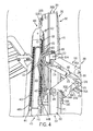
Fig. 4 is a right side view of an upper portion of the monomast and showing a portion of the hydraulic system for providing hydraulic fluid to the fork carriage apparatus; -
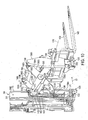
Fig. 5 is a left side view of the materials handling vehicle illustrating a reach mechanism for the fork carriage apparatus; -
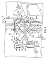
Fig. 6 is a right side cut-away view of the fork carriage apparatus in an extended position; -
Fig. 7 is a right side cut-away view of the fork carriage apparatus in a retracted position; -
Fig. 8 is a right side perspective view of the fork carriage apparatus in a retracted position; -
Fig. 9 is a top perspective view of an alternative embodiment of the fork carriage apparatus in an extended position; -
Fig. 10 is a right rear perspective view of the alternative embodiment ofFig. 9 showing the fork carriage apparatus in an extended position; -
Fig. 11 is a right side cut-away view of the alternative embodiment ofFig. 9 showing the fork carriage apparatus in a retracted position; -
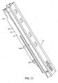
Fig. 12 is a right side front perspective view of the third stage weldment; -
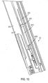
Fig. 13 is a right side rear perspective view of the third stage weldment; -
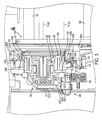
Fig. 14 is a perspective view of a rear portion of the monomast and fork carriage apparatus with a power unit of the vehicle and a third stage weldment removed; and -
Fig. 15 is a rear view of the third stage weldment illustrating the cylinder of the fork carriage lift structure coupled to the third stage weldment rear plate. -
Fig. 1 illustrates a top view of arider reach truck 100. A monomast 200, afork carriage apparatus 300 and a fork carriageapparatus lift structure 400, constructed in accordance with the present invention, are incorporated into therider reach truck 100, see alsoFig. 3 . While the present invention is described herein with reference to therider reach truck 100, it will be apparent to those skilled in the art that the invention and variations of the invention can be more generally applied to a variety of other materials handling vehicles, such as a sit-down counterbalanced truck or a stand-up counterbalanced truck. - The
truck 100 further includes avehicle power unit 102, seeFigs. 1 and2 , including a longitudinal centerline CL100, seeFig. 1 . Thepower unit 102 houses a battery (not shown) for supplying power to a traction motor coupled to a steerable wheel (not shown) mounted near a first corner at the rear 102A of thepower unit 102. Mounted to a second corner at the rear 102A of thepower unit 102 is a caster wheel (not shown). A pair ofoutriggers mohomasfframe 210, seeFig. 2 . Theoutriggers supports wheels lift apparatus structure 400 and to a mast weldment lift structure (not shown). - The
vehicle power unit 102 includes an operator'scompartment 110, which, in the illustrated embodiment, is positioned on a side of the longitudinal centerline CL100 of thevehicle power unit 102 opposite a side where themonomast 200 is positioned, seeFig. 1 . An operator standing in thecompartment 110 may control the direction of travel of thetruck 100 via atiller 120. The operator may also control the travel speed of thetruck 100, and height, extension, tilt and side shift of first andsecond forks Fig. 1 . The first andsecond forks fork carriage apparatus 300. - The
monomast 200 has a longitudinal centerline CL200, seeFig. 1 . As is apparent fromFig. 1 , the monomast longitudinal centerline CL200 is offset from, i.e., spaced laterally from, the longitudinal centerline CL100 of thevehicle power unit 102. Further, the monomast longitudinal centerline CL200 is substantially parallel with the longitudinal centerline CL100 of thevehicle power unit 102. Because the monomast longitudinal centerline CL200 is not angled or oblique to the longitudinal centerline CL100 of thevehicle power unit 102, the overall length of thetruck 100 in a direction parallel to the monomast longitudinal centerline CL200 can be minimized, i.e., made shorter than a truck including a monomast having a longitudinal centerline that is not parallel to a longitudinal centerline of the vehicle power unit. In the illustrated embodiment, the monomast longitudinal centerline CL200 is laterally offset approximately 8 inches from the longitudinal centerline CL200 of thevehicle power unit 102, see arrow LO inFig. 1 , wherein thevehicle power unit 102 has a width W of about 42 inches. These dimensions can be varied, as will be apparent to one skilled in the art. - The
monomast 200 comprises afirst stage weldment 230, asecond stage weldment 240 positioned to telescope over thefirst stage weldment 230 and athird stage weldment 250 positioned to telescope over the first andsecond stage weldments Fig. 3 . Themonomast 200 may be constructed in essentially the same manner as the monomast disclosed inUS 2010/0065377 A1 entitled MONOMAST FOR A MATERIALS HANDLING VEHICLE. Themonomast 200 further comprises a mast weldment lift structure (not shown), which effects staged lifting movement of the second andthird stage weldments first stage weldment 230. The mast weldment lift structure may be constructed in the same manner as the mast weldment lift structure set out inUS 2010/0065377 A1 entitled MONOMAST FOR A MATERIALS HANDLING VEHICLE. As is apparent fromFigs. 2 and3 , themonomast 200 comprises a single structure having a unitary tubular form and does not comprise spaced-apart vertical channels or rails joined by horizontal members wherein an open area is located between the spaced-apart vertical channels or rails. - The
fork carriage apparatus 300 is coupled to thethird stage weldment 250 so as to move vertically relative to thethird stage weldment 250, seeFig. 4 . Thefork carriage apparatus 300 also moves vertically with thethird stage weldment 250 relative to the first andsecond stage weldments fork carriage apparatus 300 comprises afork carriage mechanism 310 to which the first andsecond forks Fig. 5 . Thefork carriage mechanism 310 is mounted to areach mechanism 320 which, in turn, is mounted to amast carriage assembly 330, seeFigs. 4 and5 . Themast carriage assembly 330 comprises amain unit 332 including first andsecond side members Figs. 3 ,4 and5 . Each of theside members rollers 334 which are received intracks 350 formed in opposing outer sides surfaces 250B and 250C of thethird stage weldment 250, seeFig. 3 . In the illustrated embodiment, themain unit 332 further comprises first, second, third and fourth vertically spaced apart and horizontally extendingcarriage frame members monomast 200, seeFigs. 4 ,5 and6 . Thecarriage frame members side members - Referring to
Figs. 4 ,5 ,6 and7 , thereach mechanism 320 comprises a pantograph or scissors structure having first and secondinner arms outer arms inner arms side members mast carriage assembly 330, and second ends 346A and 346B pivotally coupled to thefork carriage mechanism 310. Each of the first ends 344A and 344B includes aroller 368. Therollers 368 are received in vertically extendingtracks 370 formed in the outer sides of theside members rollers 368 engaged within thetracks 370 form a sliding coupling between the first ends 344A and 344B of theinner arms side members - The first and second
outer arms side members mast carriage assembly 330, and second ends 356A and 356B pivotally coupled to thefork carriage mechanism 310, seeFigs. 4 ,5 ,6 and7 . Each of theside members pivot location 372 where the first ends 354A and 354B of the first and secondouter arms side members Figs. 4 and5 . - The first and second
inner arms outer arms pivot connections 358, seeFigs. 4 ,5 and6 . A hydraulic piston/cylinder apparatus 373 is provided for effecting movement of thereach mechanism 320. In the illustrated embodiment, the piston/cylinder apparatus 373 comprises acylinder 374 extending from each of theside members ram 376 extending to acoupling tab 378 provided on each of the first and secondouter arms Figs. 4 ,5 ,6 ,7 and8 . Movement of therams 376 out of thecylinders 374 effects pivotal movement of theouter arms side members fork carriage mechanism 310 in a longitudinal direction, as designated by arrow LD inFig. 7 , to an extended position, seeFigs. 4 and5 . Movement of therams 376 into thecylinders 374 effects movement of thefork carriage mechanism 310 to a retracted position locating thefork carriage mechanism 310 adjacent to themonomast 200, seeFigs. 7 and8 . It is contemplated that the piston/cylinder apparatus 373 may be coupled to the first and secondinner arms outer arms - Referring to
Figs. 3 ,5 and8 , thefork carriage mechanism 310 generally comprises in the illustrated embodiment a pair ofvertical plates fork frame members vertical plates supports fork frame member 382A, seeFigs. 5 ,6 and7 . The second ends 346A and 346B of the first and secondinner arms supports connection locations 386, and the second ends 356A and 356B of the first and secondouter arms vertical plates connection locations 388, seeFigs. 5 ,6 and8 (only the connection ofouter arm 352B tovertical plate 380B is shown in the drawings). Theforks side shift structure 384 forming part of thecarriage frame mechanism 310. In the illustrated embodiment, theside shift structure 384 comprises a conventional side shift apparatus that allows theforks transverse axis 392, seeFig. 8 . - A
cross member structure 360 extends between the first and secondinner arms 342A and 342-B and comprises in the illustrated embodiment first, second, third and fourth laterally extendingcross members Fig. 6 . The lateral edges or ends of thecross members front edges inner arms Figs. 4 and6 . Thecross members front edges inner arms Fig. 6 . Thecross member structure 360 together with theinner arms inner arm weldment 366 that functions to substantially resist torsional forces applied to thereach mechanism 320, such as through load forces applied on thefork carriage mechanism 310, seeFigs. 4 ,5 and6 . The area within theinner arm weldment 366, i.e., behind thecross member structure 360, comprises an open pocket OP for receiving thefork carriage assembly 330 during retracting movement of thereach mechanism 320, as is described further below, seeFig. 6 . Although thecross members inner arm weldment 366, in the illustrated embodiment, the first, second andthird cross members fourth cross member 362D has a rectangular solid or plate-like cross section, seeFigs. 6 and7 . - In the retracted position of the
fork carriage mechanism 310, thecross members inner arm weldment 366 and one or more of thecarriage frame members mast carriage assembly 320 are preferably located in a first common vertical plane P302 extending substantially parallel to the front side FS of themonomast 200, seeFig. 7 . Thecarriage frame members cross members cross members carriage frame members fork carriage mechanism 310 is in the retracted position. Similarly, thefork frame members cross members fork frame members cross members monomast 200, when thefork carriage mechanism 310 is in the retracted position, seeFig. 7 . The space between at least two of thecross members carriage frame member 332B, and at least onefork frame member 382A, as illustrated inFig. 7 by thefork frame member 382A having a square cross section. - The arrangement of the
cross members carriage frame members fork frame members cross member structure 360 to thefork carriage assembly 330 and, hence, to the front of themonomast 200 and close positioning of thefork carriage mechanism 310 to theinner arm weldment 366, to minimize the overall longitudinal length of thefork carriage apparatus 300 in the longitudinal direction LD, and hence the overall longitudinal length of thetruck 100 in the longitudinal direction LD, when thefork carriage mechanism 310 is in the retracted position, seeFig. 7 and8 . - The compact configuration of the
fork carriage apparatus 300 in relation to themonomast 200 is additionally facilitated by the inner andouter arms side members mast carriage assembly 330, seeFigs. 7 and8 . By locating thecross member structure 360 adjacent thefront edges inner arms inner arm weldment 366 may be positioned extending around thefork carriage assembly 330 and themonomast 200 with thevertical plates fork carriage mechanism 310 positioned along the outer sides of theouter arms reach mechanism 320, seeFigs. 3 and8 . - The fork carriage
apparatus lift structure 400 comprises a hydraulic piston/cylinder apparatus 410 including acylinder 412 and aram 414, seeFig. 4 . Thecylinder 412 is fixedly coupled to aside section 257D of a third stage weldmentrear plate 257 via first and secondupper coupling elements lower coupling elements Figs. 3 ,12 ,13 ,14 and15 . The firstupper coupling element 1257E is welded to theside section 257D of the third stage weldmentrear plate 257, seeFigs. 3 ,12 and13 . The secondupper coupling element 1257F is welded to thecylinder 412, seeFigs. 14 and15 . The firstupper coupling element 1257E and the secondupper coupling element 1257F are bolted together viabolts 3257A, seeFigs. 14 and15 . The firstlower coupling element 2257E is welded to theside section 257D of the third stage weldmentrear plate 257, seeFigs. 12 ,13 and15 . The secondlower coupling element 2257F is welded to thecylinder 412, seeFig. 15 . The firstlower coupling element 2257E and the secondlower coupling element 2257F are joined viapin 3257B, seeFig. 15 . Thecylinder 412 is mounted to arear portion 1257D of theside section 257D near anintersection 257F of theside section 257D and aback section 257G of therear plate 257, seeFigs. 3 and13 . - First and
second pulleys ram 414, seeFig. 4 . Alift chain 440 extends over thefirst pulley 420 and is coupled at afirst end 440A to thecylinder 412 via chain anchors and abracket 441 welded to thecylinder 412 and at itssecond end 440B to themast carriage assembly 330, seeFig. 4 . Vertical movement of theram 414 effects vertical movement of the entirefork carriage apparatus 300 relative to thethird stage weldment 250. Supply and returnhydraulic hoses 430 extend over thesecond pulley 422 or a separate pulley, seeFig. 4 . Thehydraulic hoses 430 define hydraulic fluid supply and return paths for thefork carriage apparatus 300. One or moreelectrical cables 431 may also extend over thesecond pulley 422, seeFigs. 4 and14 . The one or moreelectrical cables 431 may control the operation of one or more electronically controlled valves forming part of thefork carriage apparatus 300. - A
hydraulic hose 600 extends over afirst pulley 1240 coupled to arear plate 247 of thesecond stage weldment 240, seeFig. 14 (thethird stage weldment 250 is not illustrated inFig. 14 ). Thehose 600 is coupled at afirst end 600A to a hydraulic supply source (not shown) on thevehicle power unit 102 and to a base of thecylinder 412 of the fork carriageapparatus lift structure 400, seeFig. 14 . - First and second hydraulic supply and return
hoses 610 extend over asecond pulley 1242 coupled to therear plate 247 of thesecond stage weldment 240, seeFig. 14 . First ends 610A of thehydraulic hoses 610 are coupled to appropriate hydraulic fluid supply and return structure provided on thevehicle power unit 102 and second ends 610B of thehydraulic hoses 610 are coupled tometal lines 620, which, in turn, are coupled to thehydraulic hoses 430 discussed above. - Referring to
Figs. 4 and5 , hydraulic fluid may be conveyed from thehydraulic hoses 430 to amanifold 456. The manifold 456 includes solenoid actuated valves (not shown) controlling supply of fluid throughhydraulic hoses 432 to afluid junction 450. Thefluid junction 450 is coupled to hydraulic fluid supply and returnstructure 452 extending to the piston/cylinder apparatus 373 coupled to thefirst arm 352A to effect movement of theram 376 relative to thecylinder 374.Metal lines 454 may extend from thefluid junction 450 around the front side of thethird stage weldment 250 to provide hydraulic fluid to the piston/cylinder apparatus 373 on the opposite side of themonomast 200, seeFig. 5 . - It should be noted that variations on the above-described structure may be provided for forming a compact longitudinal length when the
fork carriage mechanism 310 is located in the retracted position. For example,Figs. 9 ,10 and11 illustrate an alternative embodiment of the fork carriage apparatus in which elements corresponding to the first described embodiment are labeled with the same reference numeral increased by 1000. In accordance with the second illustrated embodiment, afork carriage apparatus 1300 comprises afork carriage mechanism 1310 to which first andsecond forks fork carriage mechanism 1310 is mounted to areach mechanism 1320 which, in turn, is mounted to amast carriage assembly 1330. Themast carriage assembly 1330 comprises amain unit 1332 including first andsecond side members Figs. 9 and10 . Each of theside members rollers 1334 which are received in thetracks 350 formed in the opposing outer side surfaces 250B and 250C of thethird stage weldment 250, seeFig. 3 . In the illustrated embodiment, themain unit 1332 further comprises first, second, third and fourth vertically spaced apart and horizontally extendingcarriage frame members monomast 200, seeFigs. 10 and11 . Thecarriage frame members side members - The
reach mechanism 1320 comprises a pantograph or scissors structure having first and secondinner arms outer arms Figs. 9 and10 . The first and secondinner arms first end 1344A is shown inFigs. 9-11 ) directly coupled to theside members mast carriage assembly 1330, and second ends 1346A and 1346B pivotally coupled to thefork carriage mechanism 1310. Each of the first ends 1344A and 1344B (1344B not shown) includes aroller 1368. Therollers 1368 are received in vertically extendingtracks 1370 formed in the outer sides of theside members rollers 1368 engaged within thetracks 1370 form a sliding coupling between the first ends 1344A and 1344B (1344B not shown) of theinner arms side members - The first and second
outer arms side members mast carriage assembly 1330, and second ends 1356A and 1356B pivotally coupled to thefork carriage mechanism 1310, seeFig. 9 . Each of theside members pivot location 1372 where the first ends 1354A and 1354B of the first and secondouter arms side members pivot connection 1372 toside member 1336A is shown), seeFigs. 9 and10 . - The first and second
inner arms outer arms pivot connections 1358, seeFigs. 9 and10 . A hydraulic piston/cylinder apparatus 1373 is provided for effecting movement of thereach mechanism 1320. In the illustrated embodiment, the piston/cylinder apparatus 1373 comprises acylinder 1374 extending from each of theside members ram 1376 extending to acoupling tab 1378 provided on each of the first and secondouter arms cylinder apparatus 1373 connected toouter arm 1352A shown), seeFigs. 9 and10 . Movement of therams 1376 out of thecylinders 1374 effects pivotal movement of theouter arms side members fork carriage mechanism 1310 in a longitudinal direction, as designated by arrow LD inFig. 10 , to an extended position, seeFigs. 9 and10 . Movement of therams 1376 into thecylinders 1374 effects movement of thefork carriage mechanism 1310 to a retracted position locating thefork carriage mechanism 1310 adjacent to themonomast 200, seeFig. 11 . It is contemplated that the piston/cylinder apparatus 1373 may be coupled to the first and secondinner arms outer arms - In the illustrated embodiment, the
fork carriage mechanism 1310 generally comprises a pair ofvertical plates fork frame members vertical plates Figs. 10 and11 . The second ends 1346A and 1346B of the first and secondinner arms vertical plates connection locations 1386, and the second ends 1356A and 1356B of the first and secondouter arms vertical plates Figs. 9 and10 . Theforks fork frame member 1382B via aside shift structure 1384 forming part of thecarriage frame mechanism 1310. In the illustrated embodiment, theside shift structure 1384 comprises a conventional hydraulically actuated side shift mechanism including a hydraulic piston/cylinder 1396 that effects movement of theforks transverse axis 1392, seeFigs. 10 and11 . Additional positioning of theforks tilt structure 1390 which in the illustrated embodiment comprises a single hydraulic piston/cylinder 1394 supported on thevertical plate 1380A for effecting tilting movement of theforks transverse axis 1392, seeFigs. 9 and10 . - A
cross member structure 1360 extends between the first and secondinner arms cross members Figs. 9 and11 . The lateral edges or ends of thecross members front edges inner arms Figs. 9 and10 . Thecross members Fig. 11 , extending adjacent to thefront edges inner arms front edge 1364B andinner arm 1342B are shown inFig. 11 ). Thecross member structure 1360 together with theinner arms inner arm weldment 1366, and the area within theinner arm weldment 1366, i.e., behind thecross member structure 1360, comprises an open pocket OP' for receiving themast carriage assembly 1330 and themonomast 200 during retracting movement of thereach mechanism 1320, seeFigs. 9 and10 . In the illustrated embodiment, the first, second andthird cross members fourth cross member 1362D has a rectangular solid or plate-like cross section, seeFig. 11 . - In the retracted position of the
fork carriage mechanism 1310, thecross members inner arm weldment 1366 and one or more of thecarriage frame members mast carriage assembly 1320 are preferably located in a first common vertical plane P'302 extending substantially parallel to the front side FS of themonomast 200, seeFig. 11 . Thecarriage frame members cross members cross members carriage frame members fork carriage mechanism 1310 is in the retracted position. Similarly, thefork frame members cross members fork frame members 1382A is formed with a rectangular cross section elongated in the vertical direction, providing sufficient structural strength to thefork carriage mechanism 1310 without overlapping a second common vertical plane P'304 passing through one or more of thecross members monomast 200, when thefork carriage mechanism 1310 is in the retracted position, seeFig. 11 . - The arrangement of the
cross members carriage frame members fork frame members cross member structure 1360 to the front of themonomast 200 and close positioning of thefork carriage mechanism 1310 to theinner arm weldment 1366, to minimize the overall longitudinal length of thefork carriage apparatus 1300 in the longitudinal direction LD, and hence the overall longitudinal length of thetruck 100 in the longitudinal direction LD, when thefork carriage mechanism 1310 is in the retracted position, seeFig. 11 . - A manifold 1456 is supported on the
side member 1336A for receiving hydraulic fluid conveyed fromhydraulic hoses 1430. Hydraulic fluid may be supplied to thehydraulic hoses 1430 by structure similar to that illustrated in the first embodiment described herein. The manifold 1456 includes solenoid actuated valves (not shown) for controlling supply of fluid throughhydraulic hoses 1432 to afluid junction 1450. Thefluid junction 1450 is coupled to hydraulic fluid supply and returnhoses 1452 extending to the piston/cylinder apparatus 1373 to effect movement of theram 1376 relative to thecylinder 1374, seeFig. 10 .Metal lines 1454 may extend from thefluid junction 1450 around the front side of thethird stage weldment 250 to provide hydraulic fluid to the piston/cylinder apparatus 1373 on the opposite side of themonomast 200, seeFig. 9 . In addition, the manifold 1456 controls the supply of hydraulic fluid via hydraulic hoses (not shown) to the piston/cylinder 1396 for effecting movement of the side shift structure 1380, and supplies hydraulic fluid via hydraulic hoses (not shown) to the piston/cylinder 1394 for effecting movement of thetilt structure 1390. - While particular embodiments of the present invention have been illustrated and described, it would be obvious to those skilled in the art that various other changes and modifications can be made without departing from the scope of the invention, as defined in the appended claims.
Claims (13)
- A materials handling vehicle comprising:a vehicle power unit (102);a monomast (200) coupled to said vehicle power unit; anda fork carriage apparatus (300; 1300) supported on said monomast;said fork carriage apparatus comprising:a mast carriage assembly (330; 1330) movably coupled to said monomast;a fork carriage mechanism (310; 1310) to which forks (402, 404; 1402, 1404) are mounted; anda reach mechanism (320; 1320) coupled to said mast carriage assembly and said fork carriage mechanism for effecting movement of said fork carriage mechanism between an extended position and a retracted position,characterised in that said mast carriage assembly includes at least one carriage frame member (332A, 332B, 332C, 332D; 1332A, 1332B, 1332C, 1332D) extending laterally across a front side of said monomast, and the reach mechanism includes at least one laterally extending cross member (362A, 362B, 362C, 362D; 1362A, 1362B, 1362C, 1362D) which is located in vertically spaced relation to said carriage frame member when said fork carriage mechanism is in said retracted position.
- The materials handling vehicle as set out in claim 1, wherein said at least one carriage frame member (332A, 332B, 332C, 332D; 1332A, 1332B, 1332C, 1332D) comprises first and second carriage frame members extending laterally across said front side of said monomast (200), and said cross member (362A, 362B, 362C, 362D; 1362A, 1362B, 1362C, 1362D) is located between said first and second carriage frame members when said fork carriage mechanism (310; 1310) is in said retracted position.
- The materials handling vehicle as set out in claim 1, wherein said carriage frame member (332A, 332B, 332C, 332D; 1332A, 1332B, 1332C, 1332D) and said cross member (362A, 362B, 362C, 362D; 1362A, 1362B, 1362C, 1362D) intersect a common vertical plane extending in front of and generally parallel to said monomast (200) when said fork carriage mechanism (310; 1310) is in said retracted position.
- The materials handling vehicle as set out in claim 1, wherein said reach mechanism (320; 1320) comprises a plurality of cross members (362A, 362B, 362C, 362D; 1362A, 1362B, 1362C, 1362D) and said carriage frame member (332A, 332B, 332C, 332D; 1332A, 1332B, 1332C, 1332D) is located between two of said cross members when said fork carriage mechanism (310; 1310) is in said retracted position.
- The materials handling vehicle as set out in claim 4, wherein said fork carriage mechanism (310; 1310) includes at least one laterally extending fork frame member (382A, 382B, 382C; 1382A, 1382B, 1382C), and said fork frame member is located between said two cross members (362A, 362B, 362C, 362D; 1362A, 1362B, 1362C, 1362D) when said fork carriage mechanism is in said retracted position.
- The materials handling vehicle as set out in claim 1, wherein said reach mechanism (320; 1320) comprises a scissors structure including:first and second inner arms (342A, 342B; 1342A, 1342B), each of said first and second inner arms including a first end (344A, 344B; 1344A, 1344B) directly coupled to said mast carriage assembly (330; 1330) and a second end (346A, 346B; 1346A, 1346B) coupled to said fork carriage mechanism (310; 1310);first and second outer arms (352A, 352B; 1352A, 1352B), each of said first and second outer arms including a first end (354A, 354B; 1354A, 1354B) directly coupled to said mast carriage assembly and a second end (356A, 356B; 1356A, 1356B) coupled to said fork carriage mechanism; andsaid first and second inner arms coupled to said first and second outer arms.
- The materials handling vehicle as set out in claim 6, wherein said at least one cross member (362A, 362B, 362C, 362D; 1362A, 1362B, 1362C, 1362D) extends between said first and second inner arms (342A, 342B; 1342A, 1342B) and has lateral edges attached adjacent to front edges of said first and second inner arms to define an inner arm weldment (366; 1366).
- The materials handling vehicle as set out in claim 7, wherein said at least one cross member (362A, 362B, 362C, 362D; 1362A, 1362B, 1362C, 1362D) is generally aligned with at least one other cross member on said reach mechanism (320; 1320) in a common plane extending adjacent to front edges of said first and second inner arms (342A, 342B; 1342A, 1342B).
- The materials handling vehicle as set out in claim 7, wherein said fork carriage mechanism (310; 1310) includes at least one laterally extending fork frame member (382A, 382B, 382C; 1382A, 1382B, 1382C) and, when said fork carriage mechanism is in said retracted position, said fork frame member and said cross member (362A, 362B, 362C, 362D; 1362A, 1362B, 1362C, 1362D) intersect a common vertical plane extending in front of and generally parallel to said monomast (200).
- The materials handling vehicle as set out in claim 6, wherein said mast carriage assembly (330; 1330) further includes first and second side members (366A, 366B; 1366A, 1366B) located for movement along outer sides of said monomast (200), and said first ends (344A, 344B, 354A, 354B; 1344A, 1344B, 1354A, 1354B;) of said inner (342A, 342B; 1342A, 1342B) and outer arms (352A, 352B; 1352A, 1352B) are coupled to said first and second side members.
- The materials handling vehicle as set out in claim 10, wherein said first ends (344A, 344B; 1344A, 1344B) of said first and second inner arms (342A, 342B; 1342A, 1342B) are supported for vertical movement along vertical tracks in said first and second side members (366A, 366B; 1366A, 1366B), and said first ends (354A, 354B; 1354A, 1354B) of said first and second outer arms (352A, 352B; 1352A, 1352B) are coupled to said first and second side members at respective pivot locations (372; 1372).
- The materials handling vehicle as set out in either claim 10 or 11, wherein said inner (342A, 342B; 1342A, 1342B) and outer arms (352A, 352B; 1352A, 1352B) extend substantially vertically and are in overlapping relationship over said first and second side members (366A, 366B; 1366A, 1366B) when said fork carriage mechanism (310; 1310) is in said retracted position.
- The materials handling vehicle as set out in either claim 10 or 11, wherein said fork carriage apparatus (300; 1300) further comprises piston/cylinder apparatus (373; 1373) coupled between at least one of said side members (366A, 366B; 1366A, 1366B) and as respective one of said outer (352A, 352B; 1352A, 1352B) or inner arms (342A, 342B; 1342A, 1342B) for actuating said reach mechanism (320; 1320) between said extended and retracted positions.
Applications Claiming Priority (3)
| Application Number | Priority Date | Filing Date | Title |
|---|---|---|---|
| US9674508P | 2008-09-12 | 2008-09-12 | |
| US9674908P | 2008-09-12 | 2008-09-12 | |
| PCT/US2009/056543 WO2010030803A1 (en) | 2008-09-12 | 2009-09-10 | Fork carriage apparatus for materials handling vehicle |
Publications (2)
| Publication Number | Publication Date |
|---|---|
| EP2342155A1 EP2342155A1 (en) | 2011-07-13 |
| EP2342155B1 true EP2342155B1 (en) | 2015-07-22 |
Family
ID=41376322
Family Applications (2)
| Application Number | Title | Priority Date | Filing Date |
|---|---|---|---|
| EP09792423.7A Active EP2331448B1 (en) | 2008-09-12 | 2009-09-10 | Monomast for a materials handling vehicle |
| EP09792427.8A Active EP2342155B1 (en) | 2008-09-12 | 2009-09-10 | Fork carriage apparatus for materials handling vehicle |
Family Applications Before (1)
| Application Number | Title | Priority Date | Filing Date |
|---|---|---|---|
| EP09792423.7A Active EP2331448B1 (en) | 2008-09-12 | 2009-09-10 | Monomast for a materials handling vehicle |
Country Status (10)
| Country | Link |
|---|---|
| US (3) | US8714311B2 (en) |
| EP (2) | EP2331448B1 (en) |
| KR (2) | KR101604240B1 (en) |
| CN (2) | CN102149624B (en) |
| AU (2) | AU2009291737B2 (en) |
| BR (2) | BRPI0918161A2 (en) |
| CA (2) | CA2736383C (en) |
| ES (1) | ES2548246T3 (en) |
| MX (3) | MX2011002734A (en) |
| WO (2) | WO2010030797A1 (en) |
Cited By (1)
| Publication number | Priority date | Publication date | Assignee | Title |
|---|---|---|---|---|
| CN105540495A (en) * | 2016-02-19 | 2016-05-04 | 龙工(上海)机械制造有限公司 | Scissor telescopic arm loader |
Families Citing this family (35)
| Publication number | Priority date | Publication date | Assignee | Title |
|---|---|---|---|---|
| MX2011002734A (en) | 2008-09-12 | 2011-04-26 | Crown Equip Corp | Fork carriage apparatus for materials handling vehicle. |
| AU2011353519B2 (en) | 2011-01-04 | 2015-09-10 | Crown Equipment Corporation | Materials handling vehicle having a manifold located on a power unit for maintaining fluid pressure at an output port at a commanded pressure corresponding to an auxiliary device operating pressure |
| EP2894122B1 (en) | 2011-02-16 | 2018-12-19 | Crown Equipment Corporation | Materials handling vehicle having control structure to measure an electric current flow into or out of a hydraulic system motor |
| US9025827B2 (en) | 2011-10-19 | 2015-05-05 | Crown Equipment Corporation | Controlling truck forks based on identifying and tracking multiple objects in an image scene |
| CN104039679A (en) * | 2011-10-21 | 2014-09-10 | 机器人工业有限公司 | A lifting apparatus |
| WO2013106245A1 (en) | 2012-01-13 | 2013-07-18 | Crown Equipment Corporation | Warm up cycle for a materials handling vehicle |
| CN102556901A (en) * | 2012-01-15 | 2012-07-11 | 浙江中力机械有限公司 | Forklift mast |
| CN102795575A (en) * | 2012-09-10 | 2012-11-28 | 朱红蔚 | Shearing fork type forwarding device of lorry-mounted loading and unloading device |
| DE102013201655A1 (en) | 2013-01-31 | 2014-07-31 | Jungheinrich Aktiengesellschaft | Lifting cylinder with a pulley device for a truck |
| EP2951121A1 (en) * | 2013-02-04 | 2015-12-09 | Crown Equipment Corporation | Reach assembly with offset pivot points for a materials handling vehicle |
| US9206024B2 (en) | 2013-03-15 | 2015-12-08 | The Raymond Corporation | Systems and methods for sensor controlled reach carriage |
| USD749289S1 (en) * | 2014-08-13 | 2016-02-09 | Cascade Corporation | Forklift fork tip |
| AU2015305672B2 (en) * | 2014-08-19 | 2020-05-07 | Crown Equipment Corporation | De-centralized operational indicator system for a materials handling vehicle |
| US9926178B2 (en) | 2014-08-20 | 2018-03-27 | Crown Equipment Corporation | Actuator in a lift truck |
| CN104355271B (en) * | 2014-10-23 | 2017-01-25 | 安徽合力股份有限公司 | Hoisting system capable of implementing high hoisting of reach truck |
| US10501296B2 (en) * | 2015-06-29 | 2019-12-10 | Palfinger Ag | Linkage system for a forklift truck |
| WO2017019655A1 (en) | 2015-07-28 | 2017-02-02 | Crown Equipment Corporation | Vehicle control module signal switchboard and input tables |
| US10377388B2 (en) | 2015-08-14 | 2019-08-13 | Crown Equipment Corporation | Model based diagnostics based on traction model |
| US10294089B2 (en) * | 2015-12-03 | 2019-05-21 | The Raymond Corporation | Systems and methods for a material handling vehicle with a floor suspension |
| US9990535B2 (en) | 2016-04-27 | 2018-06-05 | Crown Equipment Corporation | Pallet detection using units of physical length |
| US10421609B2 (en) * | 2016-05-23 | 2019-09-24 | Crown Equipment Corporation | Materials handling vehicle comprising hand-held drive unit |
| KR20180001290U (en) | 2016-10-26 | 2018-05-04 | 현대건설기계 주식회사 | Forklift |
| DE102016120842B4 (en) | 2016-11-02 | 2019-12-19 | Jungheinrich Aktiengesellschaft | Industrial truck with a single mast |
| DE102016124506A1 (en) * | 2016-12-15 | 2018-06-21 | Jungheinrich Aktiengesellschaft | Truck with a control unit for controlling the movement of a load and a corresponding method |
| EP3568332B1 (en) | 2017-01-13 | 2021-11-03 | Crown Equipment Corporation | High speed straight ahead tiller desensitization |
| MX2019008406A (en) | 2017-01-13 | 2019-09-16 | Crown Equip Corp | Traction speed recovery based on steer wheel dynamic. |
| US10662047B2 (en) | 2017-03-30 | 2020-05-26 | The Raymond Corporation | Extendable mast systems and methods for a material handling vehicle |
| US10793407B1 (en) | 2017-03-31 | 2020-10-06 | Rightline Equipment, Inc. | High visibility push-pull forklift attachment |
| US11274022B2 (en) * | 2018-05-03 | 2022-03-15 | Hyster-Yale Group, Inc. | Pantograph assembly for lift truck |
| USD891022S1 (en) | 2018-07-25 | 2020-07-21 | Zhejiang E-P Equipment Co., Ltd. | Powered Stacker Vehicle |
| TWI743389B (en) * | 2018-08-30 | 2021-10-21 | 張志峰 | Transportation Equipment |
| US11352243B2 (en) | 2018-09-13 | 2022-06-07 | Crown Equipment Corporation | System and method for controlling a maximum vehicle speed for an industrial vehicle based on a calculated load |
| CN109179269A (en) * | 2018-11-21 | 2019-01-11 | 长沙长泰智能装备有限公司 | A kind of high AGV of heavy duty roller bearing type stacks of cargo |
| CN110451432B (en) * | 2019-08-21 | 2021-02-05 | 广东博智林机器人有限公司 | Transfer robot |
| CN113788437A (en) * | 2021-09-14 | 2021-12-14 | 杭州联核科技有限公司 | Unmanned reach fork truck |
Family Cites Families (72)
| Publication number | Priority date | Publication date | Assignee | Title |
|---|---|---|---|---|
| US2635711A (en) * | 1949-08-27 | 1953-04-21 | Clark Equipment Co | Hand lift truck |
| US2747689A (en) * | 1952-08-30 | 1956-05-29 | Elwell Parker Electric Co | Tier lift truck |
| USRE24958E (en) * | 1954-09-30 | 1961-03-28 | G ehmann | |
| US2915144A (en) * | 1955-10-31 | 1959-12-01 | Hyster Co | Free lift truck |
| US2925888A (en) * | 1956-03-28 | 1960-02-23 | Ver Westdeutsche Waggonfab | Lift post especially for lift trucks |
| DE1131146B (en) | 1957-03-11 | 1962-06-07 | Kloeckner Humboldt Deutz Ag | Side loader with a front, laterally offset lifting mast |
| US2973878A (en) | 1957-06-24 | 1961-03-07 | Raymond Corp | Material handling truck |
| US3035663A (en) * | 1959-12-04 | 1962-05-22 | Linde Eismaschinen Ag | Mast for conveyer vehicles |
| DE1189922B (en) | 1959-12-04 | 1965-03-25 | Linde Eismasch Ag | Loader with telescopic central mast |
| US3095945A (en) * | 1959-12-22 | 1963-07-02 | Lift A Loft Corp | Overhead service unit |
| US3082894A (en) * | 1960-06-09 | 1963-03-26 | Raymond Corp | Lift truck reach mechanism |
| US3061045A (en) | 1960-11-21 | 1962-10-30 | Multi Lift Co | Friction-free load hoisting mast |
| GB1031772A (en) * | 1962-04-13 | 1966-06-02 | Lansing Bagnall Ltd | Improvements in or relating to fork and like load-lifting trucks |
| DE1257676B (en) * | 1962-12-06 | 1967-12-28 | Aloysius Thedorus Van Huet | Loader with scissors serving to advance the load carrier |
| US3372823A (en) * | 1965-10-04 | 1968-03-12 | Raymond Corp | Lift truck mast tilting arrangement |
| DE1456892C3 (en) | 1966-05-06 | 1975-05-28 | Steinbock Gmbh, 8052 Moosburg | Telescopic mast lift drive for a lift truck |
| US3534664A (en) | 1967-09-06 | 1970-10-20 | Eaton Yale & Towne | Lift truck mast and ram assembly |
| US3485323A (en) * | 1967-09-06 | 1969-12-23 | Eaton Yale & Towne | Lift truck mast and ram assembly |
| US3472341A (en) * | 1967-12-18 | 1969-10-14 | Crown Controls Corp | Lift truck with telescopic mast |
| US3490633A (en) * | 1968-02-01 | 1970-01-20 | Case Co J I | Assembly for laterally shifting and pivoting a mast of a lift truck |
| JPS4833578B1 (en) * | 1969-02-25 | 1973-10-15 | ||
| JPS4833577B1 (en) | 1969-09-27 | 1973-10-15 | ||
| JPS4833577A (en) * | 1971-09-01 | 1973-05-11 | ||
| US3998345A (en) * | 1974-04-05 | 1976-12-21 | Missouri Research Laboratories, Inc. | Side loader for fork lift trucks |
| BG27536A3 (en) | 1974-06-26 | 1979-11-12 | Linde Ag,De | Telescopic gieting apparatus for highlifters |
| US3968859A (en) * | 1974-12-23 | 1976-07-13 | Allis-Chalmers Corporation | Multiple hose guide arrangement for a lift truck |
| US3998346A (en) * | 1975-02-03 | 1976-12-21 | The Raymond Corporation | Material handling apparatus |
| US4019786A (en) | 1975-04-30 | 1977-04-26 | Towmotor Corporation | Shielded side thrust roller assembly for lift truck mast units |
| US3972388A (en) * | 1975-08-04 | 1976-08-03 | Towmotor Corporation | Lift truck mast assembly with a resilient chain positioner |
| US3987870A (en) * | 1975-11-03 | 1976-10-26 | Towmotor Corporation | Mast assembly |
| US4051970A (en) | 1975-11-07 | 1977-10-04 | K-D Manufacturing Company | Lift truck load handling mast |
| US4084715A (en) * | 1976-02-23 | 1978-04-18 | Caterpillar Tractor Co. | Lift truck with means to pivot mast and the fork carriage thereon |
| JPS52123066A (en) * | 1976-04-07 | 1977-10-15 | Toyo Umpanki Co Ltd | Fully free three-stage mast |
| JPS5410783A (en) | 1977-06-27 | 1979-01-26 | Ngk Spark Plug Co | Glow plug for temperature detector |
| US4258825A (en) * | 1978-05-18 | 1981-03-31 | Collins Pat L | Powered manlift cart |
| US4355703A (en) * | 1979-03-08 | 1982-10-26 | Clark Equipment Company | Upright for lift truck |
| US4354579A (en) * | 1980-06-30 | 1982-10-19 | Low Leonard J | Apparatus for guiding lift truck mast segments |
| US4552250A (en) * | 1983-04-22 | 1985-11-12 | Crown Controls Corporation | Lift truck |
| US4543031A (en) * | 1983-04-22 | 1985-09-24 | Crown Controls Corporation | Apparatus for sideshift carriage control |
| JPS606598A (en) * | 1983-06-27 | 1985-01-14 | 小松フオ−クリフト株式会社 | Mast device |
| SE460116B (en) * | 1985-02-01 | 1989-09-11 | Jungheinrich Kg | TRANSPORTDON, IN PARTICULAR STACKING VEHICLE |
| GB2199302A (en) * | 1986-12-22 | 1988-07-06 | Carelift Equipment Limited | Telescopic mast assembly |
| JPH0833577B2 (en) | 1988-04-20 | 1996-03-29 | 富士写真フイルム株式会社 | Automatic exposure equipment for copiers |
| US5046585A (en) * | 1989-02-23 | 1991-09-10 | Kabushiki Kaisha Toyoda Jidoshokki Seisakusho | Upright assembly for fork lift truck |
| US4944368A (en) * | 1989-05-25 | 1990-07-31 | Duderstadt J Christopher | Lift truck having improved single mast and bearing wheel assembly |
| US5022496A (en) * | 1989-12-05 | 1991-06-11 | Crown Equipment Corporation | Slowdown during staging of a turret stockpicker |
| JPH079909Y2 (en) | 1990-04-25 | 1995-03-08 | 東洋運搬機株式会社 | forklift |
| JPH079909A (en) | 1993-06-24 | 1995-01-13 | Sekisui Chem Co Ltd | Lodge for vehicle |
| US5645142A (en) * | 1994-04-18 | 1997-07-08 | Genie Industries | Wedge braking system for multi-stage lifts |
| US5515945A (en) | 1994-04-18 | 1996-05-14 | Genie Industries, Inc. | Multi-stage mast assembly for portable lifts |
| JP2788193B2 (en) * | 1994-07-25 | 1998-08-20 | リンナイ株式会社 | Pottery cooker |
| US5657834A (en) | 1994-08-30 | 1997-08-19 | Crown Equipment Corporation | Mast staging cushion apparatus |
| US5586620A (en) * | 1995-05-12 | 1996-12-24 | Crown Equipment Corporation | Remote viewing apparatus for fork lift trucks |
| DE29514676U1 (en) * | 1995-09-13 | 1997-01-30 | Jungheinrich Ag | Forklift |
| US5803204A (en) * | 1995-10-23 | 1998-09-08 | Upright, Inc. | Personnel lift with clamshell cage assembly |
| KR0111588Y1 (en) | 1995-12-30 | 1997-12-22 | Daewoo Heavy Ind Co Ltd | Structure of establishment of attachment oil pressure in fork lift truck |
| US5850892A (en) * | 1997-01-23 | 1998-12-22 | Genie Industries, Inc. | Personnel lift with adjustable shim wear blocks |
| CA2303989C (en) * | 1997-09-30 | 2006-12-12 | Crown Equipment Corporation | Productivity package |
| NL1007308C2 (en) | 1997-10-17 | 1999-04-20 | Cangaru Forklift B V | Lift truck for engaging, moving and depositing loads |
| DE59908811D1 (en) | 1999-04-21 | 2004-04-15 | Crown Gabelstapler Gmbh | Reach truck |
| US6757958B1 (en) * | 2000-05-11 | 2004-07-06 | Jlg Omniquip, Inc. | Load handler with modular frame assembly |
| US20020100644A1 (en) * | 2001-01-31 | 2002-08-01 | Stringer Matthew D. | Mast assembly |
| GB2375341B (en) * | 2001-05-11 | 2004-09-08 | Lansing Linde Ltd | load handling device for an industrial truck |
| CN2510474Y (en) | 2001-09-15 | 2002-09-11 | 安徽合力股份有限公司 | Rubber-type pulley type forklift gear oil-supply mechanism |
| US6533076B1 (en) * | 2002-02-06 | 2003-03-18 | Crown Equipment Corporation | Materials handling vehicle mast height sensor |
| DE10225080C1 (en) * | 2002-06-05 | 2003-12-04 | Yale Ind Products Gmbh | Fork lift truck has monomast offset from vehicle central longitudinal axis with its central plane intersecting latter at acute angle |
| US7096999B2 (en) | 2003-08-05 | 2006-08-29 | The Raymond Corporation | Mast construction for a lift truck |
| US7344000B2 (en) * | 2004-09-23 | 2008-03-18 | Crown Equipment Corporation | Electronically controlled valve for a materials handling vehicle |
| US20060070816A1 (en) * | 2004-09-30 | 2006-04-06 | Schroder Werner G | Lift truck with central mast |
| JP4833577B2 (en) | 2005-04-05 | 2011-12-07 | 古河電気工業株式会社 | Manufacturing apparatus and manufacturing method for internally grooved tube |
| US20070080024A1 (en) | 2005-09-27 | 2007-04-12 | David Langenkamp | Pulley assembly for a materials handling vehicle mast assembly |
| MX2011002734A (en) | 2008-09-12 | 2011-04-26 | Crown Equip Corp | Fork carriage apparatus for materials handling vehicle. |
-
2009
- 2009-09-10 MX MX2011002734A patent/MX2011002734A/en active IP Right Grant
- 2009-09-10 CN CN200980135436.9A patent/CN102149624B/en active Active
- 2009-09-10 US US12/557,116 patent/US8714311B2/en active Active
- 2009-09-10 WO PCT/US2009/056534 patent/WO2010030797A1/en active Application Filing
- 2009-09-10 BR BRPI0918161A patent/BRPI0918161A2/en not_active Application Discontinuation
- 2009-09-10 EP EP09792423.7A patent/EP2331448B1/en active Active
- 2009-09-10 KR KR1020117008244A patent/KR101604240B1/en active IP Right Grant
- 2009-09-10 CN CN2009801410636A patent/CN102186763B/en active Active
- 2009-09-10 CA CA2736383A patent/CA2736383C/en active Active
- 2009-09-10 EP EP09792427.8A patent/EP2342155B1/en active Active
- 2009-09-10 CA CA2736384A patent/CA2736384C/en active Active
- 2009-09-10 KR KR1020117007916A patent/KR101604239B1/en active IP Right Grant
- 2009-09-10 BR BRPI0918537A patent/BRPI0918537A2/en not_active Application Discontinuation
- 2009-09-10 MX MX2011002736A patent/MX341580B/en active IP Right Grant
- 2009-09-10 WO PCT/US2009/056543 patent/WO2010030803A1/en active Application Filing
- 2009-09-10 US US12/557,146 patent/US8851825B2/en active Active
- 2009-09-10 AU AU2009291737A patent/AU2009291737B2/en active Active
- 2009-09-10 ES ES09792427.8T patent/ES2548246T3/en active Active
- 2009-09-10 AU AU2009291731A patent/AU2009291731B2/en active Active
-
2011
- 2011-03-11 MX MX2021001621A patent/MX2021001621A/en unknown
-
2014
- 2014-07-15 US US14/331,650 patent/US10144626B2/en active Active
Cited By (1)
| Publication number | Priority date | Publication date | Assignee | Title |
|---|---|---|---|---|
| CN105540495A (en) * | 2016-02-19 | 2016-05-04 | 龙工(上海)机械制造有限公司 | Scissor telescopic arm loader |
Also Published As
Similar Documents
| Publication | Publication Date | Title |
|---|---|---|
| EP2342155B1 (en) | Fork carriage apparatus for materials handling vehicle | |
| US10023448B2 (en) | Lift truck with mast | |
| US6571913B2 (en) | Multipurpose machine | |
| AU2006315241B2 (en) | A materials handling vehicle with a manifold apparatus including a valve structure mounted on the mast assembly | |
| US3490633A (en) | Assembly for laterally shifting and pivoting a mast of a lift truck | |
| EP0545877B1 (en) | A lifting vehicle for stacking loads | |
| US6439827B1 (en) | Load handling vehicle | |
| GB2327077A (en) | Compact load handling vehicle | |
| US20070068740A1 (en) | Fluid supply hose coupling structure for a materials handling vehicle | |
| JP2001247299A (en) | Forklift |
Legal Events
| Date | Code | Title | Description |
|---|---|---|---|
| PUAI | Public reference made under article 153(3) epc to a published international application that has entered the european phase |
Free format text: ORIGINAL CODE: 0009012 |
|
| 17P | Request for examination filed |
Effective date: 20110412 |
|
| AK | Designated contracting states |
Kind code of ref document: A1 Designated state(s): AT BE BG CH CY CZ DE DK EE ES FI FR GB GR HR HU IE IS IT LI LT LU LV MC MK MT NL NO PL PT RO SE SI SK SM TR |
|
| AX | Request for extension of the european patent |
Extension state: AL BA RS |
|
| DAX | Request for extension of the european patent (deleted) | ||
| 17Q | First examination report despatched |
Effective date: 20131107 |
|
| GRAP | Despatch of communication of intention to grant a patent |
Free format text: ORIGINAL CODE: EPIDOSNIGR1 |
|
| INTG | Intention to grant announced |
Effective date: 20150225 |
|
| GRAS | Grant fee paid |
Free format text: ORIGINAL CODE: EPIDOSNIGR3 |
|
| GRAA | (expected) grant |
Free format text: ORIGINAL CODE: 0009210 |
|
| AK | Designated contracting states |
Kind code of ref document: B1 Designated state(s): AT BE BG CH CY CZ DE DK EE ES FI FR GB GR HR HU IE IS IT LI LT LU LV MC MK MT NL NO PL PT RO SE SI SK SM TR |
|
| REG | Reference to a national code |
Ref country code: GB Ref legal event code: FG4D |
|
| REG | Reference to a national code |
Ref country code: CH Ref legal event code: EP |
|
| REG | Reference to a national code |
Ref country code: IE Ref legal event code: FG4D |
|
| REG | Reference to a national code |
Ref country code: AT Ref legal event code: REF Ref document number: 737767 Country of ref document: AT Kind code of ref document: T Effective date: 20150815 |
|
| REG | Reference to a national code |
Ref country code: DE Ref legal event code: R096 Ref document number: 602009032398 Country of ref document: DE |
|
| REG | Reference to a national code |
Ref country code: ES Ref legal event code: FG2A Ref document number: 2548246 Country of ref document: ES Kind code of ref document: T3 Effective date: 20151015 |
|
| REG | Reference to a national code |
Ref country code: NL Ref legal event code: FP |
|
| REG | Reference to a national code |
Ref country code: AT Ref legal event code: MK05 Ref document number: 737767 Country of ref document: AT Kind code of ref document: T Effective date: 20150722 |
|
| REG | Reference to a national code |
Ref country code: LT Ref legal event code: MG4D |
|
| REG | Reference to a national code |
Ref country code: FR Ref legal event code: PLFP Year of fee payment: 7 |
|
| PG25 | Lapsed in a contracting state [announced via postgrant information from national office to epo] |
Ref country code: LT Free format text: LAPSE BECAUSE OF FAILURE TO SUBMIT A TRANSLATION OF THE DESCRIPTION OR TO PAY THE FEE WITHIN THE PRESCRIBED TIME-LIMIT Effective date: 20150722 Ref country code: LV Free format text: LAPSE BECAUSE OF FAILURE TO SUBMIT A TRANSLATION OF THE DESCRIPTION OR TO PAY THE FEE WITHIN THE PRESCRIBED TIME-LIMIT Effective date: 20150722 Ref country code: FI Free format text: LAPSE BECAUSE OF FAILURE TO SUBMIT A TRANSLATION OF THE DESCRIPTION OR TO PAY THE FEE WITHIN THE PRESCRIBED TIME-LIMIT Effective date: 20150722 Ref country code: NO Free format text: LAPSE BECAUSE OF FAILURE TO SUBMIT A TRANSLATION OF THE DESCRIPTION OR TO PAY THE FEE WITHIN THE PRESCRIBED TIME-LIMIT Effective date: 20151022 Ref country code: GR Free format text: LAPSE BECAUSE OF FAILURE TO SUBMIT A TRANSLATION OF THE DESCRIPTION OR TO PAY THE FEE WITHIN THE PRESCRIBED TIME-LIMIT Effective date: 20151023 |
|
| PG25 | Lapsed in a contracting state [announced via postgrant information from national office to epo] |
Ref country code: AT Free format text: LAPSE BECAUSE OF FAILURE TO SUBMIT A TRANSLATION OF THE DESCRIPTION OR TO PAY THE FEE WITHIN THE PRESCRIBED TIME-LIMIT Effective date: 20150722 Ref country code: IS Free format text: LAPSE BECAUSE OF FAILURE TO SUBMIT A TRANSLATION OF THE DESCRIPTION OR TO PAY THE FEE WITHIN THE PRESCRIBED TIME-LIMIT Effective date: 20151122 Ref country code: SE Free format text: LAPSE BECAUSE OF FAILURE TO SUBMIT A TRANSLATION OF THE DESCRIPTION OR TO PAY THE FEE WITHIN THE PRESCRIBED TIME-LIMIT Effective date: 20150722 Ref country code: PT Free format text: LAPSE BECAUSE OF FAILURE TO SUBMIT A TRANSLATION OF THE DESCRIPTION OR TO PAY THE FEE WITHIN THE PRESCRIBED TIME-LIMIT Effective date: 20151123 Ref country code: PL Free format text: LAPSE BECAUSE OF FAILURE TO SUBMIT A TRANSLATION OF THE DESCRIPTION OR TO PAY THE FEE WITHIN THE PRESCRIBED TIME-LIMIT Effective date: 20150722 Ref country code: HR Free format text: LAPSE BECAUSE OF FAILURE TO SUBMIT A TRANSLATION OF THE DESCRIPTION OR TO PAY THE FEE WITHIN THE PRESCRIBED TIME-LIMIT Effective date: 20150722 |
|
| REG | Reference to a national code |
Ref country code: DE Ref legal event code: R097 Ref document number: 602009032398 Country of ref document: DE |
|
| PG25 | Lapsed in a contracting state [announced via postgrant information from national office to epo] |
Ref country code: EE Free format text: LAPSE BECAUSE OF FAILURE TO SUBMIT A TRANSLATION OF THE DESCRIPTION OR TO PAY THE FEE WITHIN THE PRESCRIBED TIME-LIMIT Effective date: 20150722 Ref country code: MC Free format text: LAPSE BECAUSE OF FAILURE TO SUBMIT A TRANSLATION OF THE DESCRIPTION OR TO PAY THE FEE WITHIN THE PRESCRIBED TIME-LIMIT Effective date: 20150722 Ref country code: DK Free format text: LAPSE BECAUSE OF FAILURE TO SUBMIT A TRANSLATION OF THE DESCRIPTION OR TO PAY THE FEE WITHIN THE PRESCRIBED TIME-LIMIT Effective date: 20150722 Ref country code: SK Free format text: LAPSE BECAUSE OF FAILURE TO SUBMIT A TRANSLATION OF THE DESCRIPTION OR TO PAY THE FEE WITHIN THE PRESCRIBED TIME-LIMIT Effective date: 20150722 Ref country code: CZ Free format text: LAPSE BECAUSE OF FAILURE TO SUBMIT A TRANSLATION OF THE DESCRIPTION OR TO PAY THE FEE WITHIN THE PRESCRIBED TIME-LIMIT Effective date: 20150722 Ref country code: LU Free format text: LAPSE BECAUSE OF FAILURE TO SUBMIT A TRANSLATION OF THE DESCRIPTION OR TO PAY THE FEE WITHIN THE PRESCRIBED TIME-LIMIT Effective date: 20150910 |
|
| REG | Reference to a national code |
Ref country code: CH Ref legal event code: PL |
|
| PLBE | No opposition filed within time limit |
Free format text: ORIGINAL CODE: 0009261 |
|
| STAA | Information on the status of an ep patent application or granted ep patent |
Free format text: STATUS: NO OPPOSITION FILED WITHIN TIME LIMIT |
|
| REG | Reference to a national code |
Ref country code: DE Ref legal event code: R082 Ref document number: 602009032398 Country of ref document: DE Representative=s name: HERNANDEZ, YORCK, DIPL.-ING., DE |
|
| PG25 | Lapsed in a contracting state [announced via postgrant information from national office to epo] |
Ref country code: RO Free format text: LAPSE BECAUSE OF FAILURE TO SUBMIT A TRANSLATION OF THE DESCRIPTION OR TO PAY THE FEE WITHIN THE PRESCRIBED TIME-LIMIT Effective date: 20150722 |
|
| 26N | No opposition filed |
Effective date: 20160425 |
|
| REG | Reference to a national code |
Ref country code: IE Ref legal event code: MM4A |
|
| PG25 | Lapsed in a contracting state [announced via postgrant information from national office to epo] |
Ref country code: CH Free format text: LAPSE BECAUSE OF NON-PAYMENT OF DUE FEES Effective date: 20150930 Ref country code: LI Free format text: LAPSE BECAUSE OF NON-PAYMENT OF DUE FEES Effective date: 20150930 Ref country code: IE Free format text: LAPSE BECAUSE OF NON-PAYMENT OF DUE FEES Effective date: 20150910 |
|
| PG25 | Lapsed in a contracting state [announced via postgrant information from national office to epo] |
Ref country code: SI Free format text: LAPSE BECAUSE OF FAILURE TO SUBMIT A TRANSLATION OF THE DESCRIPTION OR TO PAY THE FEE WITHIN THE PRESCRIBED TIME-LIMIT Effective date: 20150722 |
|
| REG | Reference to a national code |
Ref country code: FR Ref legal event code: PLFP Year of fee payment: 8 |
|
| PG25 | Lapsed in a contracting state [announced via postgrant information from national office to epo] |
Ref country code: MT Free format text: LAPSE BECAUSE OF FAILURE TO SUBMIT A TRANSLATION OF THE DESCRIPTION OR TO PAY THE FEE WITHIN THE PRESCRIBED TIME-LIMIT Effective date: 20150722 |
|
| PG25 | Lapsed in a contracting state [announced via postgrant information from national office to epo] |
Ref country code: HU Free format text: LAPSE BECAUSE OF FAILURE TO SUBMIT A TRANSLATION OF THE DESCRIPTION OR TO PAY THE FEE WITHIN THE PRESCRIBED TIME-LIMIT; INVALID AB INITIO Effective date: 20090910 Ref country code: SM Free format text: LAPSE BECAUSE OF FAILURE TO SUBMIT A TRANSLATION OF THE DESCRIPTION OR TO PAY THE FEE WITHIN THE PRESCRIBED TIME-LIMIT Effective date: 20150722 Ref country code: BG Free format text: LAPSE BECAUSE OF FAILURE TO SUBMIT A TRANSLATION OF THE DESCRIPTION OR TO PAY THE FEE WITHIN THE PRESCRIBED TIME-LIMIT Effective date: 20150722 |
|
| PG25 | Lapsed in a contracting state [announced via postgrant information from national office to epo] |
Ref country code: CY Free format text: LAPSE BECAUSE OF FAILURE TO SUBMIT A TRANSLATION OF THE DESCRIPTION OR TO PAY THE FEE WITHIN THE PRESCRIBED TIME-LIMIT Effective date: 20150722 |
|
| PG25 | Lapsed in a contracting state [announced via postgrant information from national office to epo] |
Ref country code: TR Free format text: LAPSE BECAUSE OF FAILURE TO SUBMIT A TRANSLATION OF THE DESCRIPTION OR TO PAY THE FEE WITHIN THE PRESCRIBED TIME-LIMIT Effective date: 20150722 |
|
| REG | Reference to a national code |
Ref country code: FR Ref legal event code: PLFP Year of fee payment: 9 |
|
| PG25 | Lapsed in a contracting state [announced via postgrant information from national office to epo] |
Ref country code: MK Free format text: LAPSE BECAUSE OF FAILURE TO SUBMIT A TRANSLATION OF THE DESCRIPTION OR TO PAY THE FEE WITHIN THE PRESCRIBED TIME-LIMIT Effective date: 20150722 |
|
| REG | Reference to a national code |
Ref country code: FR Ref legal event code: PLFP Year of fee payment: 10 |
|
| PGFP | Annual fee paid to national office [announced via postgrant information from national office to epo] |
Ref country code: NL Payment date: 20200925 Year of fee payment: 12 |
|
| PGFP | Annual fee paid to national office [announced via postgrant information from national office to epo] |
Ref country code: IT Payment date: 20200922 Year of fee payment: 12 |
|
| PGFP | Annual fee paid to national office [announced via postgrant information from national office to epo] |
Ref country code: ES Payment date: 20201120 Year of fee payment: 12 |
|
| REG | Reference to a national code |
Ref country code: NL Ref legal event code: MM Effective date: 20211001 |
|
| PG25 | Lapsed in a contracting state [announced via postgrant information from national office to epo] |
Ref country code: NL Free format text: LAPSE BECAUSE OF NON-PAYMENT OF DUE FEES Effective date: 20211001 |
|
| PG25 | Lapsed in a contracting state [announced via postgrant information from national office to epo] |
Ref country code: IT Free format text: LAPSE BECAUSE OF NON-PAYMENT OF DUE FEES Effective date: 20210910 |
|
| REG | Reference to a national code |
Ref country code: ES Ref legal event code: FD2A Effective date: 20221107 |
|
| PG25 | Lapsed in a contracting state [announced via postgrant information from national office to epo] |
Ref country code: ES Free format text: LAPSE BECAUSE OF NON-PAYMENT OF DUE FEES Effective date: 20210911 |
|
| P01 | Opt-out of the competence of the unified patent court (upc) registered |
Effective date: 20230529 |
|
| PGFP | Annual fee paid to national office [announced via postgrant information from national office to epo] |
Ref country code: GB Payment date: 20230920 Year of fee payment: 15 |
|
| PGFP | Annual fee paid to national office [announced via postgrant information from national office to epo] |
Ref country code: FR Payment date: 20230928 Year of fee payment: 15 Ref country code: DE Payment date: 20230920 Year of fee payment: 15 Ref country code: BE Payment date: 20230920 Year of fee payment: 15 |