EP2333521A1 - Procédé et appareil permettant d'améliorer la clarté et la sensibilité de l'image en tomographie à cohérence optique au moyen d'une interaction permettant de contrôler les propriétés focales et la synchronisation de cohérence - Google Patents
Procédé et appareil permettant d'améliorer la clarté et la sensibilité de l'image en tomographie à cohérence optique au moyen d'une interaction permettant de contrôler les propriétés focales et la synchronisation de cohérence Download PDFInfo
- Publication number
- EP2333521A1 EP2333521A1 EP10182892A EP10182892A EP2333521A1 EP 2333521 A1 EP2333521 A1 EP 2333521A1 EP 10182892 A EP10182892 A EP 10182892A EP 10182892 A EP10182892 A EP 10182892A EP 2333521 A1 EP2333521 A1 EP 2333521A1
- Authority
- EP
- European Patent Office
- Prior art keywords
- electromagnetic radiation
- scan
- sample
- image
- distance
- Prior art date
- Legal status (The legal status is an assumption and is not a legal conclusion. Google has not performed a legal analysis and makes no representation as to the accuracy of the status listed.)
- Granted
Links
Images


Classifications
-
- G—PHYSICS
- G01—MEASURING; TESTING
- G01N—INVESTIGATING OR ANALYSING MATERIALS BY DETERMINING THEIR CHEMICAL OR PHYSICAL PROPERTIES
- G01N21/00—Investigating or analysing materials by the use of optical means, i.e. using sub-millimetre waves, infrared, visible or ultraviolet light
- G01N21/17—Systems in which incident light is modified in accordance with the properties of the material investigated
- G01N21/47—Scattering, i.e. diffuse reflection
- G01N21/4795—Scattering, i.e. diffuse reflection spatially resolved investigating of object in scattering medium
-
- A—HUMAN NECESSITIES
- A61—MEDICAL OR VETERINARY SCIENCE; HYGIENE
- A61B—DIAGNOSIS; SURGERY; IDENTIFICATION
- A61B5/00—Measuring for diagnostic purposes; Identification of persons
- A61B5/0059—Measuring for diagnostic purposes; Identification of persons using light, e.g. diagnosis by transillumination, diascopy, fluorescence
- A61B5/0062—Arrangements for scanning
- A61B5/0066—Optical coherence imaging
-
- A—HUMAN NECESSITIES
- A61—MEDICAL OR VETERINARY SCIENCE; HYGIENE
- A61B—DIAGNOSIS; SURGERY; IDENTIFICATION
- A61B5/00—Measuring for diagnostic purposes; Identification of persons
- A61B5/0059—Measuring for diagnostic purposes; Identification of persons using light, e.g. diagnosis by transillumination, diascopy, fluorescence
- A61B5/0062—Arrangements for scanning
- A61B5/0068—Confocal scanning
-
- A—HUMAN NECESSITIES
- A61—MEDICAL OR VETERINARY SCIENCE; HYGIENE
- A61B—DIAGNOSIS; SURGERY; IDENTIFICATION
- A61B5/00—Measuring for diagnostic purposes; Identification of persons
- A61B5/0059—Measuring for diagnostic purposes; Identification of persons using light, e.g. diagnosis by transillumination, diascopy, fluorescence
- A61B5/0082—Measuring for diagnostic purposes; Identification of persons using light, e.g. diagnosis by transillumination, diascopy, fluorescence adapted for particular medical purposes
- A61B5/0084—Measuring for diagnostic purposes; Identification of persons using light, e.g. diagnosis by transillumination, diascopy, fluorescence adapted for particular medical purposes for introduction into the body, e.g. by catheters
-
- A—HUMAN NECESSITIES
- A61—MEDICAL OR VETERINARY SCIENCE; HYGIENE
- A61B—DIAGNOSIS; SURGERY; IDENTIFICATION
- A61B5/00—Measuring for diagnostic purposes; Identification of persons
- A61B5/68—Arrangements of detecting, measuring or recording means, e.g. sensors, in relation to patient
- A61B5/6846—Arrangements of detecting, measuring or recording means, e.g. sensors, in relation to patient specially adapted to be brought in contact with an internal body part, i.e. invasive
- A61B5/6847—Arrangements of detecting, measuring or recording means, e.g. sensors, in relation to patient specially adapted to be brought in contact with an internal body part, i.e. invasive mounted on an invasive device
- A61B5/6852—Catheters
- A61B5/6853—Catheters with a balloon
-
- G—PHYSICS
- G01—MEASURING; TESTING
- G01B—MEASURING LENGTH, THICKNESS OR SIMILAR LINEAR DIMENSIONS; MEASURING ANGLES; MEASURING AREAS; MEASURING IRREGULARITIES OF SURFACES OR CONTOURS
- G01B9/00—Measuring instruments characterised by the use of optical techniques
- G01B9/02—Interferometers
- G01B9/02049—Interferometers characterised by particular mechanical design details
- G01B9/0205—Interferometers characterised by particular mechanical design details of probe head
-
- G—PHYSICS
- G01—MEASURING; TESTING
- G01B—MEASURING LENGTH, THICKNESS OR SIMILAR LINEAR DIMENSIONS; MEASURING ANGLES; MEASURING AREAS; MEASURING IRREGULARITIES OF SURFACES OR CONTOURS
- G01B9/00—Measuring instruments characterised by the use of optical techniques
- G01B9/02—Interferometers
- G01B9/02055—Reduction or prevention of errors; Testing; Calibration
- G01B9/02062—Active error reduction, i.e. varying with time
- G01B9/02063—Active error reduction, i.e. varying with time by particular alignment of focus position, e.g. dynamic focussing in optical coherence tomography
-
- G—PHYSICS
- G01—MEASURING; TESTING
- G01B—MEASURING LENGTH, THICKNESS OR SIMILAR LINEAR DIMENSIONS; MEASURING ANGLES; MEASURING AREAS; MEASURING IRREGULARITIES OF SURFACES OR CONTOURS
- G01B9/00—Measuring instruments characterised by the use of optical techniques
- G01B9/02—Interferometers
- G01B9/02055—Reduction or prevention of errors; Testing; Calibration
- G01B9/02062—Active error reduction, i.e. varying with time
- G01B9/02067—Active error reduction, i.e. varying with time by electronic control systems, i.e. using feedback acting on optics or light
- G01B9/02068—Auto-alignment of optical elements
-
- G—PHYSICS
- G01—MEASURING; TESTING
- G01B—MEASURING LENGTH, THICKNESS OR SIMILAR LINEAR DIMENSIONS; MEASURING ANGLES; MEASURING AREAS; MEASURING IRREGULARITIES OF SURFACES OR CONTOURS
- G01B9/00—Measuring instruments characterised by the use of optical techniques
- G01B9/02—Interferometers
- G01B9/02083—Interferometers characterised by particular signal processing and presentation
- G01B9/02085—Combining two or more images of different regions
-
- G—PHYSICS
- G01—MEASURING; TESTING
- G01B—MEASURING LENGTH, THICKNESS OR SIMILAR LINEAR DIMENSIONS; MEASURING ANGLES; MEASURING AREAS; MEASURING IRREGULARITIES OF SURFACES OR CONTOURS
- G01B9/00—Measuring instruments characterised by the use of optical techniques
- G01B9/02—Interferometers
- G01B9/0209—Low-coherence interferometers
- G01B9/02091—Tomographic interferometers, e.g. based on optical coherence
-
- G—PHYSICS
- G01—MEASURING; TESTING
- G01B—MEASURING LENGTH, THICKNESS OR SIMILAR LINEAR DIMENSIONS; MEASURING ANGLES; MEASURING AREAS; MEASURING IRREGULARITIES OF SURFACES OR CONTOURS
- G01B2290/00—Aspects of interferometers not specifically covered by any group under G01B9/02
- G01B2290/35—Mechanical variable delay line
Definitions
- the present invention relates to methods for optical imaging using a low coherence light beam reflected from a sample surface and compared to a reference light beam, wherein real time dynamic optical feedback is used to detect the surface position of a tissue sample with respect to a reference point and the necessary delay scan range.
- the present also relates to an imaging probe apparatus for implementing the method.
- Optical coherence tomography is an imaging technique that measures the interference between a reference beam of light and a detected beam of light that has impinged on a target tissue area and been reflected by scatterers within tissue back to a detector.
- OCT imaging of blood vessels an imaging probe is inserted into a blood vessel and a 360 degree circular scan is taken of the vessel wall in series of segments of a predetermined arc to produce a single cross sectional image.
- the probe tip is rotated axially to create a circular scan of a tissue section and also longitudinally to scan a blood vessel segment length, thus providing two-dimensional mapped information of tissue structure.
- the axial position of the probe within the lumen remains constant with respect to the axial center of the lumen.
- the surface of the wall may vary in topography or geometry, resulting in the variance of the distance between the probe tip and the surface. Since conventional OCT imaging uses a fixed waveform to create the incident light beam in a schematically rectangular "window" of a certain height, the variation in surface height of the wall may result in the failure to gather tissue data in certain regions of the blood vessel wall. It would desirable to have a feedback mechanism that would cause the modification of the waveform to shift the window based on where the probe is and what it sees.
- the identification of the tissue surface could be used to adjust the starting position of the scan to a different spot.
- the identification of the surface could also be used to adjust the focal location in the sample arm. It would additionally be desirable if the identification of the attenuation of light within the tissue were used to adjust the scan range.
- the attenuation identification could also be used to determine an optimal depth of focus or confocal parameter.
- the present invention provides methods for optical imaging using a low coherence light beam reflected from a sample surface and compared to a reference light beam, wherein real time dynamic optical feedback is used to detect the surface position of a tissue sample with respect to a reference point and the necessary delay scan range.
- the present also relates to an imaging probe apparatus for implementing the method. The probe initially scans along one line until it finds the tissue surface, identifiable as a sharp transition from no signal to a stronger signal. The next time the probe scans the next line it adjusts the waveform depending on the previous scan.
- the present invention provides a time delay scanning unit as described herein.
- the present invention also provides a focus adjusting mechanism for an optical scanning system.
- the present invention also provides a method of time delay scanning to more accurately determine probe to tissue surface distance variations due to surface topography and probe length/design.
- the present invention provides a rocking mirror, as one of several novel mechanisms, to create the delay line.
- a rocking mirror can be moved much faster and more accurately to retain synchronicity with the computer and the scanning probe.
- the present invention provides an algorithm to determine position to determine the changes to the galvanometric DC offset angle to conform to tissue distance from the probe tip.
- the present invention provides dynamic active feedback to alter the galvanometric AC angle to adjust the coherence gate scan depth to contain only useful image information.
- the present invention also is capable of using dynamic active feedback to adjust the focusing properties of the catheter (focal length, spot size, and confocal parameter).
- Fig. 1 is a graph of a seradyne waveform of a conventional DC baseline offset, where L R is the reference arm optical delay distance offset and t is time (e.g., 0-20kHz).
- L R is the reference arm optical delay distance offset
- t is time (e.g., 0-20kHz).
- One scan image length is shown as “e 1 " and a second is shown as “e 2 ".
- the peak-to-peak amplitude is called the AC component.
- Fig. 2A shows a graph of the vessel wall offset contour of one contour scan waveform where the x-axis is time and the y-axis is ⁇ L.
- Fig. 2B shows the normal (constant offset) scanning wave of ⁇ L R which is a seradyne wave and is shown in where each period is a single scan image (shown as bracketed Axial Scan 1 having a scan image length of e1 and Axial Scan 2 having a scan image length of e2). In a given contour there can be somewhere in the range of 250-500 seradyne scans.
- Fig. 2A shows the offset correction for a period of a single scan.
- Fig. 2C shows the superimposition of the contour ⁇ L of Fig. 2A onto the seradyne waveform of Fig. 2B .
- "A" is the start gate;
- “B” is the tissue or vessel surface;
- “C” is the inside tissue;
- “D” is the end gate; and
- e is the waveform period.
- Fig. 2D shows the compensated reference arm scan over a period of two axial scans e 1 and e 2 .
- a small image window is desirable to reduce signal to noise level.
- the scan is started at offset "a" (start gate) which is slightly away from the vessel surface so that the vessel surface is at the top of the scan. This is useful in establishing the initial scan offset (starting measurement) for determination of the algorithm (as discussed in detail below).
- the difference between "b” and “a”, expressed as b-a is the deadspace between the outside and the vessel surface.
- b-c is the area inside the vessel surface.
- Fig. 3A is a graph of the scan depth control.
- Fig. 3B is a cross-sectional representation of the lumen and the scan range of Fig. 3A .
- the innermost circle is the catheter 1, the next circle outward is the vessel lumen 2, the next circle outward is the blood vessel wall 3, and the maximum scan range is indicated at 4.
- the "+" in a circle area is the useful scan range; the- (minus sign) in a circle is beyond the useful scan range.
- Fig. 3C is an image of the cross section of an actual scan.
- Fig. 4 shows a comparison of the traditional OCT image window, shown as a square labeled 5 (in solid line) and a window obtainable using the algorithm of the present invention where the image window labeled as 6 (in dashed line).
- the smaller window 6 has much higher signal to noise ratio and therefore provides significantly increased sensitivity, resulting in an improved image quality.
- the scan waveform has a constant AC component and a fixed DC, or slowly varying component,.
- the AC component of the waveform as well as the DC component vary with the feedback from the algorithm. See Fig. 5 : "D", the initial offset and ⁇ z the useful scan range is observed to determine how to modify the waveform for the next scan.
- Fig. 6 is a graph of the modified galvanometric waveform mapped to conform the reference arm delay to the tissue surface contour.
- Figs. 7A-C show successive delay scan lines of the reference arm.
- Fig. 7A1 and 7A2 shows amplitude a 1 and ⁇ z 1 .
- Fig. 8A shows ⁇ x versus ⁇ L.
- Fig. 8B shows time versus L R .
- the DC offset follows the curve representing the tissue surface contour, as in Fig. 8B .
- Scan 1, Scan 2, etc., of Fig. 8A maps onto Scan 1 and Scan 2 of Fig. 8B .
- Successive scans 3, 4, ... N are adjusted for tissue surface offset and optimal scan range in a similar manner.
- Examination of the data in the present scan line (axial scan) or scan lines determines the offset to the tissue surface and the optimal coherence gate for the following N scan lines. In this manner, real-time dynamic feedback is provided and enables imaging of irregular tissue contours with an optimal sensitivity.
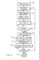
- Fig. 9 shows a flow diagram of ⁇ the algorithm according to one embodiment of the present invention.
- a first scan line is taken at block 10 sufficient to find the tissue surface "S" at block 12 at a relatively large scan range (block 14) (for example, about 3-10 mm, although other ranges can be used as appropriate).
- block 14 a relatively large scan range
- To find the surface one of at least three methods can be used.
- the first method is to use the adaptive threshold ("T").
- Such filtration may be achieved using any of a number of filters know to those skilled in the art, including, but not limited to, linear blur, Gaussian, windows, low pass filters, convolution, morphology, and the like. If the surface is not found, repeat block 10, but change the range offset based on the results at block 12. For example, if there is no signal, the offset and range may be altered in a random manner. If there is a signal but it is weak and did not exceed an adaptive threshold, the offset is adjusted (i.e., move the S mild gate toward the signal and try again). That offset is made based on the intensity of reflect light detected by the detector.
- sheath plus internal reflections is catheter based, or signal based, where the highest signal is inside the tissue. In such a case there may be more than one location "z" which has the derivatives >T.
- Fig. 10 shows four possible hits. There is only one that corresponds to the tissue surface. ⁇ is a small increment. Peak "A” shows an isolated hit where there is no appreciable signal on either side of the peak; therefore, for z A - ⁇ ⁇ z A ⁇ z A + ⁇ , there is I(z A ⁇ ) ⁇ I(z).
- Peak “B” shows a peak where there is no signal before (i.e., to the left) but there is signal after (i.e., to the right); therefore, for z B - ⁇ ⁇ z B there is I(z B - ⁇ ) ⁇ I(z B ) and I(z B ) ⁇ I(z B + ⁇ ).
- Fig. 10 shows four cases where the signal (image data) threshold is exceeded.
- Peak “A” has no signal before or after it (i.e., within the next pixel, increment or ⁇ ) it (sometimes referred to as above (z 0 ) or below (z max )); therefore, it is discounted.
- Peak “D” is discounted for the same reason/rule: it has no signal before or after it. For peak “C” there is signal before it and after it, therefore it cannot be at the surface. For peak “B” there is signal after it, but not before it. Therefore, peak “B” indicates the start of the tissue surface boundary.
- Fig. 11 shows a scan line.
- the optimal scan range R is what is to be determined.
- the curve is smoothed (see methods mentioned above).
- Third, decrease z (i.e., move z towards S) until I(z) starts to increase again; i.e., I(z') > I(z max ) and where R z'-S.
- a basic operating parameter is that one wants minimal signal outside of and as much signal as possible inside of the scan range R. This can be achieved by zeroth order, first derivative, second derivative, probability distribution functions statistics (e.g., standard deviation), fitting to exponential and other standard data analysis procedures known in the art.
- Spikes in noise, but which are artifacts which could be counted in a signal solution can be a potential problem.
- the reference arm delay waveform is modified at block 16.
- S and R can be used to modify the waveform controlling the optical delay line.
- S and R now need to be inserted into an equation which controls the galvanometric waveform.
- G(t) f(S,R,t), where G(t) is the galvanometric waveform and f is a function.
- This G(t) is sent digitally or analog to the galvanometric waveform.
- Fig. 12 shows the array of the output/storage of the galvanometric waveform to computer memory block 20 and which goes to remapping at block 28, where "N" is the number of axial scans per image.
- This S,R array indicates how to remap the data into real space again for block 28 (of Fig.9 ).
- Fig. 13A shows the old and Fig. 14B shows the new window attainable from block 28 (refer back to Fig. 9 and accompanying description of reference letters).
- I(x,z) are inserted into a remapping function with the inputs being an away of S, R to create the remapped image of block 28.
- S and R for every line, x, there are different elements, S and R, in the away (i.e., So corresponds to I(x 0 ,z) and z is continuous. This relates to the distance between the probe and the chosen range.
- Remapping (block 28 of Fig. 9 ) is preferably done after each scan.
- the image is remapped after acquisition:
- remapping is done interactively. Add each S that is known for each of the scan lines (the vertical bars) to the data and the contour is remapped. S is added to the offset of the image. In other words, shifting the data for any given exposition by S.
- Each vertical bar gets (axial scan) remapped (shifted) based on their respective S value. For example, is the z values in x 1 are offset by S 1 .
- I x n ⁇ z I acq ⁇ x n , z - S n
- I x n ⁇ z I acq ⁇ x n , z - S n - 1
- I x n ⁇ z I acq ⁇ x n , z - S n + 1
- n identifies a specific axial scan and where n is close to where mapping is occurring.
- the output is sent to the reference arm at block 18 and also saved in the computer at block 20. If the image is not done at block 22, the next scan line is taken at block 24 by cycling back repeatedly to block 12 until the image is acquired. If the image is done, then the image is remapped at block 28 using the surface S information and the modified reference arm delay waveform stored and recalled from the computer memory from block 20. The image is then saved or displayed at block 30. If no other image at block 32 is to be taken, the process is done at block 40.
- the algorithm queries at block 34 whether a new location is taken. If yes, then at line 36 the first scan line is taken back at block 10. If no image is scanned at line 38, then the next surface location S is found at block 12.
- Fig. 14 shows flow diagram for an autofocus algorithm.
- Sn and Rn are known, then an optimal focal length is also known and the optimal spot size and confocal parameters can be calculated. If some function "g" is applied to the catheter which causes a change in focus by z f , and which occurs at pixel "n" where one knows S n , then all one needs to know is, if one is at S k then one can calculate how g changes as (S k -S n ). Therefore, for a given n, one knows what one has to do to the catheter to obtain a focus of z f (n). S n is also known. So, S n+1 creates g(n+1) for all n.
- S allows one to adjust the focus so that it is optimally present within or at the surface of the tissue.
- R allows one to adjust the confocal parameter so that the spot size is minimized over the optimal scan range.
- a key feature of the present invention is that one can calculate where to move the focus if one position is known. One does not have to iteratively modify the focus until it is optimized each time, only once, and, once S is calculated, modify focus thereafter using the previous or present S of the scan.
- the present invention allows imaging of tissue with an irregular surface and keeping substantially the entire image in view. Moreover, the scan range is decreased so as to only include useful image information, therefore decreasing the bandwidth of the signal and increasing the image sensitivity of even possibly up to some 3-5 times.
- the sensitivity increase may be implemented by decreasing the bandwidth of the filter used reject noise while performing heterodyne or lock-in detection. This filter bandwidth may be adjusted dynamically by using diode switched capacitor array. Increasing sensitivity is equivalent to increasing speed while keeping accuracy.
- the present invention also has the advantage of compensating for probe length variation.
- the present invention provides a time delay scanning unit as described herein.
- the present invention also provides a focus adjusting mechanism for an optical scanning system.
- the present invention also provides a method of time delay scanning to more accurately determine probe to tissue surface distance variations due to surface topography and probe length/design.
- Fig. 15 shows an algorithm for confocal parameter adjustment during confocal microscopy analysis.
- the confocal parameter is optimized to R, the optimal scan gate range.
- the optimal grating range R (as previously described hereinabove) is determined, block 212.
- the optimal confocal parameter 2z R is calculated at block 214.
- the catheter confocal parameter is modified at block 216 for some 2z e >(R+ ⁇ ). If the image is not done at block 218, go to the next scan line 220. If the scan is done, end at block 222.
- 2z R (2 ⁇ 0 2 )/ ⁇ , where ⁇ 0 is the beam radius; ⁇ is wavelength, and 2z R is the confocal parameter.
- Fig. 16 shows a schematic of an apparatus according to one embodiment of the present invention.
- the basic description of this and the subsequent drawings is found in Ozawa et al., U.S. Patent No. 6,069,698 , which is incorporated herein.
- the basic description of the relevant parts of Fig. 16 corresponds to Figure 1 of Ozawa et al.
- Fig. 17 shows a schematic of the delay line.
- the galvanometer is a motor that attaches to the mirror and actuates partial tilt/rotation of the mirror. Only one delay is necessary, although more than one delay line is possible.
- a diffraction grating having a period which changes as a function of time to make the mirror fixed and not rotating. Simple, blazed, or other grating known to those of ordinary skill in the art, can be used.
- the grating sends different wavelengths to a lens and a galvanometric scanning mirror which alters the optical delay in the reference arm as a function of mirror angle.
- Fig. 18 is a schematic diagram of an alternative system in which the delay line is created by a mirror 84 is reciprocatingly mounted on a linear translator 85 which is controlled by a motor/driving unit 86 and 87.
- a description of basic components Fig. 18 is found in the specification corresponding to Figure 11 of Ozawa et al.
- the mirror 84 oscillates at a certain rate.
- the algorithms would have the mirror 84 scan back and forth and gradually shifts its translation over time to track the surface of the tissue. Each time the mirror 84 scans, it is called one scan or one axis of probing.
- Fig. 19 (similar to Figure 6 of Ozawa et al.) is a schematic diagram showing a further alternative system in which a drum 65 controlled by a computer 25. Small changes to the diameter of the drum, induced by piezoelectries, stretch the thin fibers wound around the drum. The increased fiber length contributes a delay line.
- Fig. 20 illustrates an alternative using an acousto-optic modulator 153 is a computer controlled diffraction grating where the periodicity of the grating can be changed based on the frequency to the acousto-optic modulator.
- Fig. 21 shows a catheter according to the present invention, and is a modification of Figure 4 of Ozawa et al.
- Fig. 22 shows a detail of a catheter according to one embodiment of the present invention.
- the design is based on Figure 4 of Ozawa et al.
- Fig. 22A (a detail of Fig. 21 ) shows the distal end of the catheter having an optical fiber fixed into block 49, which fixes the fiber to the spring.
- the present invention uses a block which can have its length altered.
- the block is a piezoelectric transducer ("piezo") 49A connected by a wire 49B.
- the voltage changes the length of the piezo 49A and therefore changes the separation (the gap) between the lens 56 and the tip of the optical fiber. Movement of the lens with respect to the fiber tip is shown in the inset Fig. 22A .
- 58 is the output beam.
- 58a is the output beam at piezo voltage Va
- 58b is the output beam at piezo voltage Vb.
- Figs. 24 and 25 are two general ways to translate a focus.
- Fig. 24 shows a schematic view of a system which illustrates that as the distance between the fiber and the lens changes, the location of the focus changes.
- the focus is shown as a solid ray tracing line.
- the focus is shown as the dashed ray tracing line.
- Magnification M i/d.
- Fig. 25 shows a schematic view of a system where the fiber-lens separation is fixed and the separation between the lens and the reflector/prism is changed.
- the light beam at distance dl has a different focal point than the light beam at distance d2.
- the translation can be achieved by any of the mechanisms described above.
- Fig. 26 shows a schematic view of a system where the gap between the fiber and a compound lens composed of multiple elements is fixed and, e. g., the gap between the lens and the reflector is fixed, but the relative separation of the gap between individual lens elements changes.
- An alternative embodiment utilizes a lens having a flexible cover and filled with an optically transparent fluid (e. g., saline, oil), gas or other substance. As the fluid composition, flexible cover shape or the like is changed, the focal length also changes.
- an optically transparent fluid e. g., saline, oil
- a method of imaging a surface position with respect to a reference point with real time feedback and correction comprising: a obtaining a first scan line; b. finding a surface location"S"; c. finding an optimal scan range"R"; d. saving said optimal scan range data in a memory storage device; e. modifying a reference arm delay waveform to provide an output; f. saving said output data of said waveform in a memory storage device; g. outputting said output to a reference arm; h. querying whether said image is complete; i. moving to the next scan line if said image is not complete or remapping said image using said surface S data and said waveform data stored in said memory storage device if said image is complete; j. saving or displaying said image.
- a method of imaging further comprising step k. obtaining an additional scan line where an additional image is to be taken and repeating steps a. through j.
- a method of imaging further comprising step f. moving to the next scan line and repeating steps b. through e. if the image is not complete.
- a method further comprising step e. moving to the next scan line and repeating steps b. through e. if the image is not complete.
- an optical imaging apparatus for imaging a sample surface, comprising: a. a light source to generate a low coherence light beam; b. an optical probe; c. a coupler detachably connectable to said optical probe by means of an optical connector and which allows the reflected sample beam and a reference beam containing the low coherence light beam to interfere with each other; d. a detector for detecting said interference; e. an image signal generator to generate image signals on the basis of signals detected by the detector; and, f. means for imparting a reference beam transmission time delay.
- said means for imparting a reference beam transmission time delay comprises a mirror capable of at least partially tilting and rotating on an axis and a galvanometer to actuate tilting and rotating of said mirror.
- a apparatus wherein said galvanometer angularly deflects said mirror in proportion to applied voltage.
- an apparatus wherein the applied voltage is determined by a drive wave comprising a triangle or seradyne wave which tracks the distance from the probe to said surface being imaged.
- an apparatus wherein said angular deflection of said mirror is done at high frequency to achieve depth scanning and is also done with a superimposed offset which corresponds to the distance between said probe and said surface.
- an apparatus wherein said time delay is done in real time.
- said means for imparting a reference beam transmission time delay comprises a diffraction grating having a period which changes as a function of time.
- an apparatus wherein said diffraction grating is simple.
- an apparatus wherein said diffraction grating is blazed.
- said means for imparting a reference beam transmission time delay comprises a mirror reciprocatingly mounted on a linear translator controlled by a motor.
- said means for imparting a reference beam transmission time delay comprises a drum having at least one optically transmissive fiber wound around said drum and a piezoelectric unit associated with said drum for altering the diameter of said drum in response to a signal from a computer so as to stretch or relax said fiber.
- said means for imparting a reference beam transmission time delay comprises a diffraction grating controlled by a computer whereby the periodicity of the grating can be altered based on the frequency of an acousto-optic modulator associated with said diffraction grating.
- an imaging probe comprising: a. a housing; b. an optical fiber having a tip, said optical fiber being at least partially disposed within said housing; c. a lens fixedly associated with said housing in proximity to said fiber tip; d. a prism associated with said lens; e. means for rotating said prism; f. a piezoelectric transducer to which said fiber is associated; g. an electrically conductive wire; and, h. means for actuating said transducer so as to alter the length of said transducer so as to alter the distance between said optical fiber tip and said lens.
- an imaging probe comprising: a. a housing; b. an optical fiber having a tip, said optical fiber being at least partially disposed within said housing; c. a lens fixedly associated with said housing in proximity to said fiber tip; d. a prism associated with said lens; e. means for rotating said prism; f. an expandable member; and g. a tube in communication with said expandable member for delivering a gas or fluid to said expandable member so as to controllably alter the distance between said fiber tip and said lens.
- an imaging probe comprising: a. a housing; b. an optical fiber having a tip, said optical fiber being at least partially disposed within said housing; c. a lens disposed within said housing in proximity to said fiber tip; d. a prism associated with said lens; e. means for rotating said prism; f. a piezoelectric transducer to which said lens is associated; g. an electrically conductive wire; and, h. means for actuating said transducer so as to alter the length of said transducer and alter the distance between said prism and said lens.
- an imaging probe comprising: a. a housing; b. an optical fiber having a tip, said optical fiber being at least partially disposed within said housing; c. a plurality of lens elements disposed within said housing in proximity to said fiber tip; d. a prism associated with said lens; e. means for rotating said prism; f. means for altering overall focal length of said plurality of lens elements.
- an imaging probe wherein said focal length altering means comprises a means for altering the relative distance between at least two of said plurality of lens elements.
- an imaging probe wherein said plurality of lens elements comprises at least one flexible lens shell containing a fluid or semi-fluid.
- an imaging probe wherein said fluid or semi-fluid changes refractive index in response to a signal.
Landscapes
- Health & Medical Sciences (AREA)
- Life Sciences & Earth Sciences (AREA)
- Physics & Mathematics (AREA)
- Engineering & Computer Science (AREA)
- General Health & Medical Sciences (AREA)
- General Physics & Mathematics (AREA)
- Pathology (AREA)
- Animal Behavior & Ethology (AREA)
- Public Health (AREA)
- Biomedical Technology (AREA)
- Heart & Thoracic Surgery (AREA)
- Medical Informatics (AREA)
- Molecular Biology (AREA)
- Surgery (AREA)
- Biophysics (AREA)
- Veterinary Medicine (AREA)
- Nuclear Medicine, Radiotherapy & Molecular Imaging (AREA)
- Radiology & Medical Imaging (AREA)
- Optics & Photonics (AREA)
- Signal Processing (AREA)
- Automation & Control Theory (AREA)
- Chemical & Material Sciences (AREA)
- Analytical Chemistry (AREA)
- Biochemistry (AREA)
- Immunology (AREA)
- Investigating Or Analysing Materials By Optical Means (AREA)
- Endoscopes (AREA)
- Instruments For Viewing The Inside Of Hollow Bodies (AREA)
Applications Claiming Priority (3)
| Application Number | Priority Date | Filing Date | Title |
|---|---|---|---|
| US28747701P | 2001-04-30 | 2001-04-30 | |
| PCT/US2002/013793 WO2002088684A1 (fr) | 2001-04-30 | 2002-04-30 | Procede et appareil permettant d'ameliorer la clarte et la sensibilite de l'image en tomographie a coherence optique au moyen d'une interaction permettant de controler les proprietes focales et la synchronisation de coherence |
| EP02734125.4A EP1402244B1 (fr) | 2001-04-30 | 2002-04-30 | Procede et appareil permettant d'ameliorer la clarte et la sensibilite de l'image en tomographie a coherence optique au moyen d'une interaction permettant de controler les proprietes focales et la synchronisation de coherence |
Related Parent Applications (3)
| Application Number | Title | Priority Date | Filing Date |
|---|---|---|---|
| EP02734125.4A Division-Into EP1402244B1 (fr) | 2001-04-30 | 2002-04-30 | Procede et appareil permettant d'ameliorer la clarte et la sensibilite de l'image en tomographie a coherence optique au moyen d'une interaction permettant de controler les proprietes focales et la synchronisation de coherence |
| EP02734125.4A Division EP1402244B1 (fr) | 2001-04-30 | 2002-04-30 | Procede et appareil permettant d'ameliorer la clarte et la sensibilite de l'image en tomographie a coherence optique au moyen d'une interaction permettant de controler les proprietes focales et la synchronisation de coherence |
| EP02734125.4 Division | 2002-04-30 |
Publications (2)
| Publication Number | Publication Date |
|---|---|
| EP2333521A1 true EP2333521A1 (fr) | 2011-06-15 |
| EP2333521B1 EP2333521B1 (fr) | 2019-12-04 |
Family
ID=23103077
Family Applications (4)
| Application Number | Title | Priority Date | Filing Date |
|---|---|---|---|
| EP10182894A Withdrawn EP2333522A1 (fr) | 2001-04-30 | 2002-04-30 | Procédé et appareil permettant d'améliorer la clarté et la sensibilité de l'image en tomographie à cohérence optique au moyen d'une interaction permettant de contrôler les propriétés focales et la synchronisation de cohérence |
| EP10182896.0A Expired - Lifetime EP2333523B1 (fr) | 2001-04-30 | 2002-04-30 | Procédé et appareil permettant d'améliorer la clarté et la sensibilité de l'image en tomographie à cohérence optique au moyen d'une interaction permettant de contrôler les propriétés focales et la synchronisation de cohérence |
| EP02734125.4A Expired - Lifetime EP1402244B1 (fr) | 2001-04-30 | 2002-04-30 | Procede et appareil permettant d'ameliorer la clarte et la sensibilite de l'image en tomographie a coherence optique au moyen d'une interaction permettant de controler les proprietes focales et la synchronisation de coherence |
| EP10182892.9A Expired - Lifetime EP2333521B1 (fr) | 2001-04-30 | 2002-04-30 | Procédé et appareil permettant d'améliorer la clarté et la sensibilité de l'image en tomographie à cohérence optique au moyen d'une interaction permettant de contrôler les propriétés focales et la synchronisation de cohérence |
Family Applications Before (3)
| Application Number | Title | Priority Date | Filing Date |
|---|---|---|---|
| EP10182894A Withdrawn EP2333522A1 (fr) | 2001-04-30 | 2002-04-30 | Procédé et appareil permettant d'améliorer la clarté et la sensibilité de l'image en tomographie à cohérence optique au moyen d'une interaction permettant de contrôler les propriétés focales et la synchronisation de cohérence |
| EP10182896.0A Expired - Lifetime EP2333523B1 (fr) | 2001-04-30 | 2002-04-30 | Procédé et appareil permettant d'améliorer la clarté et la sensibilité de l'image en tomographie à cohérence optique au moyen d'une interaction permettant de contrôler les propriétés focales et la synchronisation de cohérence |
| EP02734125.4A Expired - Lifetime EP1402244B1 (fr) | 2001-04-30 | 2002-04-30 | Procede et appareil permettant d'ameliorer la clarte et la sensibilite de l'image en tomographie a coherence optique au moyen d'une interaction permettant de controler les proprietes focales et la synchronisation de coherence |
Country Status (4)
| Country | Link |
|---|---|
| US (1) | US9897538B2 (fr) |
| EP (4) | EP2333522A1 (fr) |
| JP (3) | JP2004528111A (fr) |
| WO (1) | WO2002088684A1 (fr) |
Families Citing this family (149)
| Publication number | Priority date | Publication date | Assignee | Title |
|---|---|---|---|---|
| DE60141090D1 (de) | 2000-10-30 | 2010-03-04 | Gen Hospital Corp | Optische systeme zur gewebeanalyse |
| JP3842101B2 (ja) * | 2000-10-31 | 2006-11-08 | 富士写真フイルム株式会社 | 内視鏡装置 |
| US9295391B1 (en) | 2000-11-10 | 2016-03-29 | The General Hospital Corporation | Spectrally encoded miniature endoscopic imaging probe |
| EP2333522A1 (fr) | 2001-04-30 | 2011-06-15 | The General Hospital Corporation | Procédé et appareil permettant d'améliorer la clarté et la sensibilité de l'image en tomographie à cohérence optique au moyen d'une interaction permettant de contrôler les propriétés focales et la synchronisation de cohérence |
| GB2408797B (en) | 2001-05-01 | 2006-09-20 | Gen Hospital Corp | Method and apparatus for determination of atherosclerotic plaque type by measurement of tissue optical properties |
| US7355716B2 (en) | 2002-01-24 | 2008-04-08 | The General Hospital Corporation | Apparatus and method for ranging and noise reduction of low coherence interferometry LCI and optical coherence tomography OCT signals by parallel detection of spectral bands |
| CN1741768A (zh) * | 2003-01-24 | 2006-03-01 | 通用医疗有限公司 | 利用低相干干涉测量法识别组织的系统和方法 |
| US8054468B2 (en) | 2003-01-24 | 2011-11-08 | The General Hospital Corporation | Apparatus and method for ranging and noise reduction of low coherence interferometry LCI and optical coherence tomography OCT signals by parallel detection of spectral bands |
| CA2519937C (fr) | 2003-03-31 | 2012-11-20 | Guillermo J. Tearney | Reduction de granularite dans la tomographie par coherence optique au moyen d'une composition angulaire par codage de longueur de trajet |
| US7844321B2 (en) * | 2003-04-28 | 2010-11-30 | Board Of Regents, The University Of Texas System | Rotating catheter probe using a light-drive apparatus |
| MXPA05011155A (es) | 2003-04-28 | 2005-12-14 | Univ Texas | Sonda y metodo de formacion de imagen de cateter. |
| EP2008579B1 (fr) | 2003-06-06 | 2016-11-09 | The General Hospital Corporation | Procédé et appareil pour une source de lumière à réglage de longueur d'onde |
| CN103181753B (zh) | 2003-10-27 | 2016-12-28 | 通用医疗公司 | 用于使用频域干涉测量法进行光学成像的方法和设备 |
| WO2005117534A2 (fr) | 2004-05-29 | 2005-12-15 | The General Hospital Corporation | Procede, systeme et logiciel destines a la compensation de dispersion chromatique au moyen de couches reflechissantes dans l'imagerie par tomographie par coherence optique (oct) |
| JP4995720B2 (ja) | 2004-07-02 | 2012-08-08 | ザ ジェネラル ホスピタル コーポレイション | ダブルクラッドファイバを有する内視鏡撮像プローブ |
| JP5053845B2 (ja) | 2004-08-06 | 2012-10-24 | ザ ジェネラル ホスピタル コーポレイション | 光学コヒーレンス断層撮影法を使用して試料中の少なくとも1つの位置を決定するための方法、システムおよびソフトウェア装置 |
| KR20120062944A (ko) | 2004-08-24 | 2012-06-14 | 더 제너럴 하스피탈 코포레이션 | 혈관절편 영상화 방법 및 장치 |
| EP1793730B1 (fr) | 2004-08-24 | 2011-12-28 | The General Hospital Corporation | Ensemble procede, systeme et logiciel pour la détermination de module d 'élasticité |
| KR101269455B1 (ko) | 2004-09-10 | 2013-05-30 | 더 제너럴 하스피탈 코포레이션 | 광 간섭 영상화를 위한 시스템 및 방법 |
| KR101257100B1 (ko) | 2004-09-29 | 2013-04-22 | 더 제너럴 하스피탈 코포레이션 | 광 간섭 영상화 시스템 및 방법 |
| EP2278267A3 (fr) | 2004-11-24 | 2011-06-29 | The General Hospital Corporation | Interféromètre à chemin commun pour OCT endoscopique |
| US8922781B2 (en) | 2004-11-29 | 2014-12-30 | The General Hospital Corporation | Arrangements, devices, endoscopes, catheters and methods for performing optical imaging by simultaneously illuminating and detecting multiple points on a sample |
| US8351665B2 (en) | 2005-04-28 | 2013-01-08 | The General Hospital Corporation | Systems, processes and software arrangements for evaluating information associated with an anatomical structure by an optical coherence ranging technique |
| US8355776B2 (en) | 2005-05-27 | 2013-01-15 | Board Of Regents, The University Of Texas System | Hemoglobin contrast in magneto-motive optical doppler tomography, optical coherence tomography, and ultrasound imaging methods and apparatus |
| US7801590B2 (en) * | 2005-05-27 | 2010-09-21 | Board Of Regents, The University Of Texas System | Optical coherence tomographic detection of cells and killing of the same |
| JP2008542758A (ja) | 2005-05-31 | 2008-11-27 | ザ ジェネラル ホスピタル コーポレイション | スペクトルコード化ヘテロダイン干渉法を画像化に使用可能なシステム、方法、及び装置 |
| EP1889037A2 (fr) | 2005-06-01 | 2008-02-20 | The General Hospital Corporation | Appareil, methode et systeme pour effectuer une imagerie de domaine de frequence optique a resolution de phase |
| US9441948B2 (en) | 2005-08-09 | 2016-09-13 | The General Hospital Corporation | Apparatus, methods and storage medium for performing polarization-based quadrature demodulation in optical coherence tomography |
| JP4892719B2 (ja) * | 2005-08-24 | 2012-03-07 | 国立大学法人大阪大学 | 断層計測装置及び断層計測方法 |
| CN101360447B (zh) | 2005-09-29 | 2012-12-05 | 通用医疗公司 | 通过光谱编码进行光学成像的方法和装置 |
| JP4545696B2 (ja) * | 2005-09-30 | 2010-09-15 | 富士フイルム株式会社 | 光プローブ |
| DE102005047200B4 (de) * | 2005-10-01 | 2021-05-06 | Carl Zeiss Microscopy Gmbh | Verfahren zur Korrektur einer Steuerung eines optischen Scanners in einer Vorrichtung zur scannenden Abbildung einer Probe und Vorrichtung zur Erzeugung eines Bildes einer Probe durch Abscannen der Probe |
| EP1945094B1 (fr) | 2005-10-14 | 2018-09-05 | The General Hospital Corporation | Imagerie fluorescente codee par frequence et par spectre |
| EP1948021A4 (fr) * | 2005-10-20 | 2009-12-02 | Univ Texas | Pointe de catheter optique rotative destinee a une tomographie par coherence optique |
| US20070162095A1 (en) * | 2006-01-06 | 2007-07-12 | Ezc Medical Llc | Modular visualization stylet apparatus and methods of use |
| US7796270B2 (en) | 2006-01-10 | 2010-09-14 | The General Hospital Corporation | Systems and methods for generating data based on one or more spectrally-encoded endoscopy techniques |
| JP4823693B2 (ja) * | 2006-01-11 | 2011-11-24 | 株式会社トプコン | 光画像計測装置 |
| US8145018B2 (en) | 2006-01-19 | 2012-03-27 | The General Hospital Corporation | Apparatus for obtaining information for a structure using spectrally-encoded endoscopy techniques and methods for producing one or more optical arrangements |
| US9087368B2 (en) | 2006-01-19 | 2015-07-21 | The General Hospital Corporation | Methods and systems for optical imaging or epithelial luminal organs by beam scanning thereof |
| EP1983921B1 (fr) | 2006-02-01 | 2016-05-25 | The General Hospital Corporation | Systèmes d'application d'un rayonnement électromagnétique sur au moins une partie d'un échantillon au moyen de procédures thérapeutiques laser conformationnelles |
| EP1986545A2 (fr) | 2006-02-01 | 2008-11-05 | The General Hospital Corporation | Appareil destiné à appliquer une pluralité de rayonnements électromagnétiques à un échantillon |
| EP1988825B1 (fr) | 2006-02-08 | 2016-12-21 | The General Hospital Corporation | Dispositifs et systèmes pour obtenir des informations associées à un prélévement anatomique utilisant la microscopie optique |
| JP4454030B2 (ja) * | 2006-02-21 | 2010-04-21 | 国立大学法人 筑波大学 | 3次元光断層画像の画像処理方法 |
| EP2309221A1 (fr) | 2006-02-24 | 2011-04-13 | The General Hospital Corporation | Procédés et systèmes destinés à réaliser une tomographie par cohérence optique dans le domaine de fourier avec résolution angulaire |
| US7742173B2 (en) | 2006-04-05 | 2010-06-22 | The General Hospital Corporation | Methods, arrangements and systems for polarization-sensitive optical frequency domain imaging of a sample |
| WO2007133961A2 (fr) | 2006-05-10 | 2007-11-22 | The General Hospital Corporation | Processus, agencements et systèmes pour obtenir une imagerie de domaine de fréquence d'un échantillon |
| US7782464B2 (en) * | 2006-05-12 | 2010-08-24 | The General Hospital Corporation | Processes, arrangements and systems for providing a fiber layer thickness map based on optical coherence tomography images |
| JP2010501877A (ja) | 2006-08-25 | 2010-01-21 | ザ ジェネラル ホスピタル コーポレイション | ボリュメトリック・フィルタリング法を使用して光コヒーレンス・トモグラフィ画像形成の機能を向上させる装置及び方法 |
| US7973927B2 (en) * | 2006-09-29 | 2011-07-05 | Uwm Research Foundation, Inc. | Two-photon microscope with spectral resolution |
| US8838213B2 (en) | 2006-10-19 | 2014-09-16 | The General Hospital Corporation | Apparatus and method for obtaining and providing imaging information associated with at least one portion of a sample, and effecting such portion(s) |
| US7911621B2 (en) | 2007-01-19 | 2011-03-22 | The General Hospital Corporation | Apparatus and method for controlling ranging depth in optical frequency domain imaging |
| WO2008089342A1 (fr) | 2007-01-19 | 2008-07-24 | The General Hospital Corporation | Réflexion de disque rotatif pour balayage de longueurs d'onde rapide de lumière à large bande dispersée |
| EP2602651A3 (fr) | 2007-03-23 | 2014-08-27 | The General Hospital Corporation | Procédés, agencements et appareil pour utiliser un laser à balayage de longueur d'ondes utilisant un balayage angulaire et des procédures de dispersion |
| US10534129B2 (en) | 2007-03-30 | 2020-01-14 | The General Hospital Corporation | System and method providing intracoronary laser speckle imaging for the detection of vulnerable plaque |
| US8045177B2 (en) | 2007-04-17 | 2011-10-25 | The General Hospital Corporation | Apparatus and methods for measuring vibrations using spectrally-encoded endoscopy |
| JP5448353B2 (ja) * | 2007-05-02 | 2014-03-19 | キヤノン株式会社 | 光干渉断層計を用いた画像形成方法、及び光干渉断層装置 |
| WO2008137637A2 (fr) | 2007-05-04 | 2008-11-13 | The General Hospital Corporation | Procédés, agencements et systèmes pour obtenir des informations associées à un échantillon à l'aide d'une microscopie optique |
| WO2009009801A1 (fr) * | 2007-07-12 | 2009-01-15 | Volcano Corporation | Appareil et procédés permettant la synchronisation d'échantillons de fréquence uniforme |
| WO2009009786A2 (fr) * | 2007-07-12 | 2009-01-15 | Board Of Regents, The University Of Texas System | Détection ultrasonique magnétomotrice de nanoparticules magnétiques |
| WO2009009802A1 (fr) | 2007-07-12 | 2009-01-15 | Volcano Corporation | Cathéter oct-ivus pour imagerie luminale simultanée |
| US9596993B2 (en) | 2007-07-12 | 2017-03-21 | Volcano Corporation | Automatic calibration systems and methods of use |
| EP2173254A2 (fr) | 2007-07-31 | 2010-04-14 | The General Hospital Corporation | Systèmes et procédés pour fournir des motifs de balayage de faisceau pour une imagerie dans le domaine de la fréquence optique doppler de vitesse élevée |
| JP5117787B2 (ja) * | 2007-08-13 | 2013-01-16 | 株式会社トプコン | 光画像計測装置 |
| JP5536650B2 (ja) | 2007-08-31 | 2014-07-02 | ザ ジェネラル ホスピタル コーポレイション | 自己干渉蛍光顕微鏡検査のためのシステムと方法、及び、それに関連するコンピュータがアクセス可能な媒体 |
| US7933021B2 (en) | 2007-10-30 | 2011-04-26 | The General Hospital Corporation | System and method for cladding mode detection |
| WO2009058656A1 (fr) * | 2007-11-01 | 2009-05-07 | Dimensional Photonics International, Inc. | Système d'imagerie tridimensionnelle intra-orale |
| WO2009089043A2 (fr) * | 2008-01-09 | 2009-07-16 | Ezc Medical Llc. | Systèmes et méthodes d'intubation |
| US11123047B2 (en) | 2008-01-28 | 2021-09-21 | The General Hospital Corporation | Hybrid systems and methods for multi-modal acquisition of intravascular imaging data and counteracting the effects of signal absorption in blood |
| US9332942B2 (en) | 2008-01-28 | 2016-05-10 | The General Hospital Corporation | Systems, processes and computer-accessible medium for providing hybrid flourescence and optical coherence tomography imaging |
| US8348429B2 (en) | 2008-03-27 | 2013-01-08 | Doheny Eye Institute | Optical coherence tomography device, method, and system |
| US11839430B2 (en) | 2008-03-27 | 2023-12-12 | Doheny Eye Institute | Optical coherence tomography-based ophthalmic testing methods, devices and systems |
| US9125562B2 (en) * | 2009-07-01 | 2015-09-08 | Avinger, Inc. | Catheter-based off-axis optical coherence tomography imaging system |
| US8593619B2 (en) | 2008-05-07 | 2013-11-26 | The General Hospital Corporation | System, method and computer-accessible medium for tracking vessel motion during three-dimensional coronary artery microscopy |
| WO2009155536A2 (fr) | 2008-06-20 | 2009-12-23 | The General Hospital Corporation | Coupleur fondu de fibres optiques et procédé associé |
| WO2010009136A2 (fr) | 2008-07-14 | 2010-01-21 | The General Hospital Corporation | Appareil et procédés d'endoscopie couleur |
| US8820931B2 (en) | 2008-07-18 | 2014-09-02 | Doheny Eye Institute | Optical coherence tomography-based ophthalmic testing methods, devices and systems |
| TWI359007B (en) * | 2008-10-29 | 2012-03-01 | Univ Nat Taiwan | Method for analyzing a mucosa sample with optical |
| ES2957932T3 (es) | 2008-12-10 | 2024-01-30 | Massachusetts Gen Hospital | Sistemas, aparatos y procedimientos para ampliar el rango de profundidad de imagen de tomografía de coherencia óptica mediante submuestreo óptico |
| WO2010085775A2 (fr) | 2009-01-26 | 2010-07-29 | The General Hospital Corporation | Système, procédé et support accessible par ordinateur permettant de fournir une microscopie de super-résolution à large champ |
| WO2010091190A2 (fr) | 2009-02-04 | 2010-08-12 | The General Hospital Corporation | Appareil et procédé d'utilisation d'une source d'ajustement de longueur d'onde optique à grande vitesse |
| US9351642B2 (en) | 2009-03-12 | 2016-05-31 | The General Hospital Corporation | Non-contact optical system, computer-accessible medium and method for measurement at least one mechanical property of tissue using coherent speckle technique(s) |
| US8416415B2 (en) | 2009-04-27 | 2013-04-09 | General Electric Company | Gas turbine optical imaging system |
| CN102469943A (zh) | 2009-07-14 | 2012-05-23 | 通用医疗公司 | 用于测量脉管内流动和压力的设备、系统和方法 |
| PT2542154T (pt) | 2010-03-05 | 2020-11-25 | Massachusetts Gen Hospital | Aparelho para proporcionar radiação eletromagnética a uma amostra |
| US9069130B2 (en) | 2010-05-03 | 2015-06-30 | The General Hospital Corporation | Apparatus, method and system for generating optical radiation from biological gain media |
| WO2011149972A2 (fr) | 2010-05-25 | 2011-12-01 | The General Hospital Corporation | Systèmes, dispositifs, procédés, appareil et supports accessibles par ordinateur pour fournir une imagerie optique de structures et de compositions |
| JP5778762B2 (ja) | 2010-05-25 | 2015-09-16 | ザ ジェネラル ホスピタル コーポレイション | 光コヒーレンストモグラフィー画像のスペクトル解析のための装置及び方法 |
| US10285568B2 (en) | 2010-06-03 | 2019-05-14 | The General Hospital Corporation | Apparatus and method for devices for imaging structures in or at one or more luminal organs |
| JP2012002597A (ja) * | 2010-06-15 | 2012-01-05 | Fujifilm Corp | 光断層画像化装置及び光断層画像化方法 |
| EP2632324A4 (fr) | 2010-10-27 | 2015-04-22 | Gen Hospital Corp | Appareil, systèmes et méthodes de mesure de la pression sanguine dans au moins un vaisseau |
| TWI519277B (zh) * | 2011-03-15 | 2016-02-01 | 明達醫學科技股份有限公司 | 皮膚光學診斷裝置及其運作方法 |
| US8982206B2 (en) | 2011-04-07 | 2015-03-17 | Uwm Research Foundation, Inc. | High speed microscope with narrow detector and pixel binning |
| JP6240064B2 (ja) | 2011-04-29 | 2017-11-29 | ザ ジェネラル ホスピタル コーポレイション | 散乱媒質の深さ分解した物理的及び/又は光学的特性を決定する方法 |
| JP2014523536A (ja) | 2011-07-19 | 2014-09-11 | ザ ジェネラル ホスピタル コーポレイション | 光コヒーレンストモグラフィーにおいて偏波モード分散補償を提供するためのシステム、方法、装置およびコンピュータアクセス可能な媒体 |
| EP3835718B1 (fr) | 2011-08-25 | 2023-07-26 | The General Hospital Corporation | Dispositif pour fournir de la tomographie par cohérence micro-optique dans un système respiratoire |
| WO2013033489A1 (fr) | 2011-08-31 | 2013-03-07 | Volcano Corporation | Raccord optique rotatif et méthodes d'utilisation |
| JP2015502562A (ja) | 2011-10-18 | 2015-01-22 | ザ ジェネラル ホスピタル コーポレイション | 再循環光学遅延を生成および/または提供するための装置および方法 |
| US8842287B2 (en) * | 2011-12-22 | 2014-09-23 | General Electric Company | System and method for auto-focusing in optical coherence tomography |
| US9629528B2 (en) | 2012-03-30 | 2017-04-25 | The General Hospital Corporation | Imaging system, method and distal attachment for multidirectional field of view endoscopy |
| KR101355174B1 (ko) | 2012-05-17 | 2014-01-28 | 한국생산기술연구원 | Oct 프로브 광궤적 보정장치 및 그 보정방법 |
| EP2852315A4 (fr) | 2012-05-21 | 2016-06-08 | Gen Hospital Corp | Appareil, dispositif et procédé pour microscopie par capsule |
| JP6227652B2 (ja) | 2012-08-22 | 2017-11-08 | ザ ジェネラル ホスピタル コーポレイション | ソフトリソグラフィを用いてミニチュア内視鏡を製作するためのシステム、方法、およびコンピュータ・アクセス可能媒体 |
| US9367965B2 (en) | 2012-10-05 | 2016-06-14 | Volcano Corporation | Systems and methods for generating images of tissue |
| US10070827B2 (en) | 2012-10-05 | 2018-09-11 | Volcano Corporation | Automatic image playback |
| US10893806B2 (en) | 2013-01-29 | 2021-01-19 | The General Hospital Corporation | Apparatus, systems and methods for providing information regarding the aortic valve |
| WO2014121082A1 (fr) | 2013-02-01 | 2014-08-07 | The General Hospital Corporation | Agencement d'objectif pour endomicroscopie confocale |
| CN113705586A (zh) | 2013-03-07 | 2021-11-26 | 飞利浦影像引导治疗公司 | 血管内图像中的多模态分割 |
| US10772497B2 (en) | 2014-09-12 | 2020-09-15 | Envision Diagnostics, Inc. | Medical interfaces and other medical devices, systems, and methods for performing eye exams |
| US9226856B2 (en) | 2013-03-14 | 2016-01-05 | Envision Diagnostics, Inc. | Inflatable medical interfaces and other medical devices, systems, and methods |
| WO2014145378A1 (fr) * | 2013-03-15 | 2014-09-18 | Research Development Foundation | Appareil et procédés pour multiplexage de longueur de trajectoire pour tomographie à cohérence optique à résolution angulaire |
| US10478072B2 (en) | 2013-03-15 | 2019-11-19 | The General Hospital Corporation | Methods and system for characterizing an object |
| EP2997354A4 (fr) | 2013-05-13 | 2017-01-18 | The General Hospital Corporation | Détection de la phase et de l'amplitude d'une fluorescence auto-interférente |
| WO2015009932A1 (fr) | 2013-07-19 | 2015-01-22 | The General Hospital Corporation | Appareil d'imagerie et procédé utilisant une endoscopie à champ de vision multidirectionnel |
| WO2015010133A1 (fr) | 2013-07-19 | 2015-01-22 | The General Hospital Corporation | Détermination de mouvement oculaire au moyen d'une imagerie de la rétine avec rétroaction r un mouvement de l'œil par imagerie de la rétine et fournir des informations en retour pour l'acquisition de signaux venant de la rétine |
| ES2893237T3 (es) | 2013-07-26 | 2022-02-08 | Massachusetts Gen Hospital | Aparato con una disposición láser que utiliza dispersión óptica para aplicaciones en la tomografía de coherencia óptica en el dominio de Fourier |
| WO2015105870A1 (fr) | 2014-01-08 | 2015-07-16 | The General Hospital Corporation | Procédé et appareil pour imagerie microscopique |
| WO2015116986A2 (fr) | 2014-01-31 | 2015-08-06 | The General Hospital Corporation | Système et procédé pour faciliter une imagerie volumétrique manuelle et/ou automatique avec un retour de tension ou d'effort en temps réel au moyen d'un dispositif d'imagerie amarré |
| WO2015153982A1 (fr) | 2014-04-04 | 2015-10-08 | The General Hospital Corporation | Appareil et procédé de commande de la propagation et/ou de la transmission d'un rayonnement électromagnétique dans un ou des guides d'ondes flexibles |
| US10912462B2 (en) | 2014-07-25 | 2021-02-09 | The General Hospital Corporation | Apparatus, devices and methods for in vivo imaging and diagnosis |
| JP6523642B2 (ja) * | 2014-09-26 | 2019-06-05 | テルモ株式会社 | 画像診断装置 |
| CN107949311B (zh) | 2015-04-16 | 2021-04-16 | Gentuity有限责任公司 | 用于神经病学的微光探针 |
| US10631718B2 (en) | 2015-08-31 | 2020-04-28 | Gentuity, Llc | Imaging system includes imaging probe and delivery devices |
| US11039741B2 (en) | 2015-09-17 | 2021-06-22 | Envision Diagnostics, Inc. | Medical interfaces and other medical devices, systems, and methods for performing eye exams |
| DE102016103954A1 (de) * | 2016-03-04 | 2017-09-07 | Blackbird Robotersysteme Gmbh | Messverfahren sowie Messvorrichtung zum Erfassen einer Oberflächentopologie eines Werkstücks |
| WO2017190087A1 (fr) | 2016-04-30 | 2017-11-02 | Envision Diagnostics, Inc. | Dispositifs, systèmes et procédés médicaux de mise en œuvre d'examens oculaires et d'oculométrie |
| US10578422B2 (en) | 2016-06-08 | 2020-03-03 | Canon U.S.A., Inc. | Devices, systems, methods and storage mediums using full range optical coherence tomography |
| WO2018119077A1 (fr) | 2016-12-21 | 2018-06-28 | Acucela Inc. | Système de tomographie par cohérence optique à faible coût, mobile et miniaturisé pour applications ophtalmiques à domicile |
| EP3700406A4 (fr) | 2017-11-28 | 2021-12-29 | Gentuity LLC | Système d'imagerie |
| JP7402866B2 (ja) | 2018-06-20 | 2023-12-21 | アキュセラ インコーポレイテッド | 家庭用眼科用途のための小型化モバイル低コスト光干渉断層撮影システム |
| US10595722B1 (en) | 2018-10-03 | 2020-03-24 | Notal Vision Ltd. | Automatic optical path adjustment in home OCT |
| CN109645936B (zh) * | 2018-12-24 | 2023-12-12 | 中国科学院苏州生物医学工程技术研究所 | 一种共聚焦内窥成像错位校正系统及方法 |
| CN216090756U (zh) | 2019-08-12 | 2022-03-22 | 巴德阿克塞斯系统股份有限公司 | 医疗装置和用于医疗装置的形状感测系统 |
| CN214804697U (zh) | 2019-11-25 | 2021-11-23 | 巴德阿克塞斯系统股份有限公司 | 光学尖端追踪系统 |
| EP4061272A4 (fr) | 2019-11-25 | 2023-11-22 | Bard Access Systems, Inc. | Systèmes de détection de forme comprenant des filtres et procédés associés |
| WO2021134087A1 (fr) | 2019-12-26 | 2021-07-01 | Acucela Inc. | Système d'alignement de patient par tomographie par cohérence optique pour applications ophtalmiques à domicile |
| EP4110175A1 (fr) | 2020-02-28 | 2023-01-04 | Bard Access Systems, Inc. | Systèmes de connexion optique et procédés associés |
| CN113456054A (zh) | 2020-03-30 | 2021-10-01 | 巴德阿克塞斯系统股份有限公司 | 光学和电气诊断系统及其方法 |
| US11622816B2 (en) | 2020-06-26 | 2023-04-11 | Bard Access Systems, Inc. | Malposition detection system |
| CN216136534U (zh) | 2020-06-29 | 2022-03-29 | 巴德阿克塞斯系统股份有限公司 | 用于将医疗装置放置入患者身体内的医疗装置系统 |
| US11624677B2 (en) | 2020-07-10 | 2023-04-11 | Bard Access Systems, Inc. | Continuous fiber optic functionality monitoring and self-diagnostic reporting system |
| US11630009B2 (en) | 2020-08-03 | 2023-04-18 | Bard Access Systems, Inc. | Bragg grated fiber optic fluctuation sensing and monitoring system |
| US10959613B1 (en) | 2020-08-04 | 2021-03-30 | Acucela Inc. | Scan pattern and signal processing for optical coherence tomography |
| WO2022035809A1 (fr) | 2020-08-14 | 2022-02-17 | Acucela Inc. | Système et procédé d'alignement par courbure décroissante de balayage a de tomographie par cohérence optique |
| US11393094B2 (en) | 2020-09-11 | 2022-07-19 | Acucela Inc. | Artificial intelligence for evaluation of optical coherence tomography images |
| CN116322471A (zh) | 2020-09-30 | 2023-06-23 | 奥克塞拉有限公司 | 近视预测、诊断、计划和监测设备 |
| CN216985791U (zh) | 2020-10-13 | 2022-07-19 | 巴德阿克塞斯系统股份有限公司 | 用于光纤连接器的消毒罩 |
| WO2022204622A1 (fr) | 2021-03-24 | 2022-09-29 | Acucela Inc. | Dispositif de surveillance de mesure de longueur axiale |
| US11802843B1 (en) | 2022-07-15 | 2023-10-31 | Know Labs, Inc. | Systems and methods for analyte sensing with reduced signal inaccuracy |
| US11953698B1 (en) * | 2023-10-10 | 2024-04-09 | Leadoptik Inc. | Spatially multiplexed diffractive lens with extended depth of field via phase correction |
Citations (3)
| Publication number | Priority date | Publication date | Assignee | Title |
|---|---|---|---|---|
| US5975697A (en) * | 1998-11-25 | 1999-11-02 | Oti Ophthalmic Technologies, Inc. | Optical mapping apparatus with adjustable depth resolution |
| US6069698A (en) | 1997-08-28 | 2000-05-30 | Olympus Optical Co., Ltd. | Optical imaging apparatus which radiates a low coherence light beam onto a test object, receives optical information from light scattered by the object, and constructs therefrom a cross-sectional image of the object |
| WO2000043730A1 (fr) * | 1999-01-20 | 2000-07-27 | Lightlab Imaging | Procedes et appareil de balayage longitudinal a grande vitesse dans des systemes d'imagerie |
Family Cites Families (230)
| Publication number | Priority date | Publication date | Assignee | Title |
|---|---|---|---|---|
| US26735A (en) * | 1860-01-03 | Washing-machine | ||
| US166593A (en) * | 1875-08-10 | Improvement in grain-meters | ||
| US135101A (en) * | 1873-01-21 | Improvement in turn-tables | ||
| US150829A (en) * | 1874-05-12 | Improvement in machines for cleaning cog-wheels | ||
| US2339754A (en) | 1941-03-04 | 1944-01-25 | Westinghouse Electric & Mfg Co | Supervisory apparatus |
| GB1257778A (fr) | 1967-12-07 | 1971-12-22 | ||
| US3601480A (en) | 1968-07-10 | 1971-08-24 | Physics Int Co | Optical tunnel high-speed camera system |
| JPS4932484U (fr) | 1972-06-19 | 1974-03-20 | ||
| FR2253410A5 (fr) | 1973-12-03 | 1975-06-27 | Inst Nat Sante Rech Med | |
| US3941121A (en) | 1974-12-20 | 1976-03-02 | The University Of Cincinnati | Focusing fiber-optic needle endoscope |
| US4141362A (en) | 1977-05-23 | 1979-02-27 | Richard Wolf Gmbh | Laser endoscope |
| GB2030313A (en) | 1978-06-29 | 1980-04-02 | Wolf Gmbh Richard | Endoscopes |
| US4295738A (en) | 1979-08-30 | 1981-10-20 | United Technologies Corporation | Fiber optic strain sensor |
| US4300816A (en) | 1979-08-30 | 1981-11-17 | United Technologies Corporation | Wide band multicore optical fiber |
| US5065331A (en) | 1981-05-18 | 1991-11-12 | Vachon Reginald I | Apparatus and method for determining the stress and strain in pipes, pressure vessels, structural members and other deformable bodies |
| US4479499A (en) | 1982-01-29 | 1984-10-30 | Alfano Robert R | Method and apparatus for detecting the presence of caries in teeth using visible light |
| US4601036A (en) | 1982-09-30 | 1986-07-15 | Honeywell Inc. | Rapidly tunable laser |
| HU187188B (en) | 1982-11-25 | 1985-11-28 | Koezponti Elelmiszeripari | Device for generating radiation of controllable spectral structure |
| CH663466A5 (fr) | 1983-09-12 | 1987-12-15 | Battelle Memorial Institute | Procede et dispositif pour determiner la position d'un objet par rapport a une reference. |
| FR2556088B1 (fr) * | 1983-12-01 | 1988-09-09 | Rech Const Electro Et | Procede pour la mesure de distance entre deux points d'observation sur la base du temps de propagation aller-retour d'un signal entre ces deux points, adapte en particulier aux turbulences du milieu de propagation, et telemetre mettant en oeuvre ce procede |
| EP0590268B1 (fr) | 1985-03-22 | 1998-07-01 | Massachusetts Institute Of Technology | Sonde comprenant des fibres optiques destiné à l'analyse spectrale de tissus |
| US4607622A (en) | 1985-04-11 | 1986-08-26 | Charles D. Fritch | Fiber optic ocular endoscope |
| US4631498A (en) | 1985-04-26 | 1986-12-23 | Hewlett-Packard Company | CW Laser wavemeter/frequency locking technique |
| US5040889A (en) | 1986-05-30 | 1991-08-20 | Pacific Scientific Company | Spectrometer with combined visible and ultraviolet sample illumination |
| US4770492A (en) | 1986-10-28 | 1988-09-13 | Spectran Corporation | Pressure or strain sensitive optical fiber |
| CA1339426C (fr) | 1987-09-01 | 1997-09-02 | Michael R. Layton | Circuit et methode de demodulation pour hydrophone |
| FR2626367B1 (fr) | 1988-01-25 | 1990-05-11 | Thomson Csf | Capteur de temperature multipoints a fibre optique |
| FR2626383B1 (fr) | 1988-01-27 | 1991-10-25 | Commissariat Energie Atomique | Procede de microscopie optique confocale a balayage et en profondeur de champ etendue et dispositifs pour la mise en oeuvre du procede |
| US4925302A (en) | 1988-04-13 | 1990-05-15 | Hewlett-Packard Company | Frequency locking device |
| EP0393165B2 (fr) * | 1988-07-13 | 2007-07-25 | Optiscan Pty Ltd | Endoscope a balayage a foyer commun |
| GB8817672D0 (en) | 1988-07-25 | 1988-09-01 | Sira Ltd | Optical apparatus |
| US4868834A (en) | 1988-09-14 | 1989-09-19 | The United States Of America As Represented By The Secretary Of The Army | System for rapidly tuning a low pressure pulsed laser |
| DE3833602A1 (de) | 1988-10-03 | 1990-02-15 | Krupp Gmbh | Spektrometer zur gleichzeitigen intensitaetsmessung in verschiedenen spektralbereichen |
| US5419323A (en) | 1988-12-21 | 1995-05-30 | Massachusetts Institute Of Technology | Method for laser induced fluorescence of tissue |
| US5317389A (en) | 1989-06-12 | 1994-05-31 | California Institute Of Technology | Method and apparatus for white-light dispersed-fringe interferometric measurement of corneal topography |
| US5039193A (en) | 1990-04-03 | 1991-08-13 | Focal Technologies Incorporated | Fibre optic single mode rotary joint |
| JPH0456907A (ja) | 1990-06-26 | 1992-02-24 | Fujikura Ltd | 光ファイバカプラ |
| US5262644A (en) | 1990-06-29 | 1993-11-16 | Southwest Research Institute | Remote spectroscopy for raman and brillouin scattering |
| US5197470A (en) | 1990-07-16 | 1993-03-30 | Eastman Kodak Company | Near infrared diagnostic method and instrument |
| GB9015793D0 (en) | 1990-07-18 | 1990-09-05 | Medical Res Council | Confocal scanning optical microscope |
| US5127730A (en) | 1990-08-10 | 1992-07-07 | Regents Of The University Of Minnesota | Multi-color laser scanning confocal imaging system |
| US5305759A (en) | 1990-09-26 | 1994-04-26 | Olympus Optical Co., Ltd. | Examined body interior information observing apparatus by using photo-pulses controlling gains for depths |
| JP3104984B2 (ja) | 1990-09-27 | 2000-10-30 | オリンパス光学工業株式会社 | 断層像観察用光走査装置 |
| JPH04135551A (ja) | 1990-09-27 | 1992-05-11 | Olympus Optical Co Ltd | 光三次元像観察装置 |
| US5202745A (en) | 1990-11-07 | 1993-04-13 | Hewlett-Packard Company | Polarization independent optical coherence-domain reflectometry |
| JP3035336B2 (ja) | 1990-11-27 | 2000-04-24 | 興和株式会社 | 血流測定装置 |
| US6198532B1 (en) | 1991-02-22 | 2001-03-06 | Applied Spectral Imaging Ltd. | Spectral bio-imaging of the eye |
| US5293872A (en) | 1991-04-03 | 1994-03-15 | Alfano Robert R | Method for distinguishing between calcified atherosclerotic tissue and fibrous atherosclerotic tissue or normal cardiovascular tissue using Raman spectroscopy |
| JPH04319345A (ja) | 1991-04-18 | 1992-11-10 | Olympus Optical Co Ltd | 光断層イメージング装置 |
| US5748598A (en) | 1995-12-22 | 1998-05-05 | Massachusetts Institute Of Technology | Apparatus and methods for reading multilayer storage media using short coherence length sources |
| US6134003A (en) | 1991-04-29 | 2000-10-17 | Massachusetts Institute Of Technology | Method and apparatus for performing optical measurements using a fiber optic imaging guidewire, catheter or endoscope |
| US5956355A (en) | 1991-04-29 | 1999-09-21 | Massachusetts Institute Of Technology | Method and apparatus for performing optical measurements using a rapidly frequency-tuned laser |
| US6501551B1 (en) | 1991-04-29 | 2002-12-31 | Massachusetts Institute Of Technology | Fiber optic imaging endoscope interferometer with at least one faraday rotator |
| US6485413B1 (en) | 1991-04-29 | 2002-11-26 | The General Hospital Corporation | Methods and apparatus for forward-directed optical scanning instruments |
| WO1992019930A1 (fr) | 1991-04-29 | 1992-11-12 | Massachusetts Institute Of Technology | Procede et appareil d'imagerie optique et de mesure |
| US6111645A (en) | 1991-04-29 | 2000-08-29 | Massachusetts Institute Of Technology | Grating based phase control optical delay line |
| US6564087B1 (en) | 1991-04-29 | 2003-05-13 | Massachusetts Institute Of Technology | Fiber optic needle probes for optical coherence tomography imaging |
| US5465147A (en) | 1991-04-29 | 1995-11-07 | Massachusetts Institute Of Technology | Method and apparatus for acquiring images using a ccd detector array and no transverse scanner |
| US5441053A (en) | 1991-05-03 | 1995-08-15 | University Of Kentucky Research Foundation | Apparatus and method for multiple wavelength of tissue |
| AU2519892A (en) | 1991-08-20 | 1993-03-16 | Douglas C.B. Redd | Optical histochemical analysis, in vivo detection and real-time guidance for ablation of abnormal tissues using a raman spectroscopic detection system |
| DE4128744C1 (fr) | 1991-08-29 | 1993-04-22 | Siemens Ag, 8000 Muenchen, De | |
| JPH05130995A (ja) | 1991-11-14 | 1993-05-28 | Olympus Optical Co Ltd | 空間差分を用いた光断層イメージング装置 |
| US5353790A (en) | 1992-01-17 | 1994-10-11 | Board Of Regents, The University Of Texas System | Method and apparatus for optical measurement of bilirubin in tissue |
| US5248876A (en) | 1992-04-21 | 1993-09-28 | International Business Machines Corporation | Tandem linear scanning confocal imaging system with focal volumes at different heights |
| US5486701A (en) | 1992-06-16 | 1996-01-23 | Prometrix Corporation | Method and apparatus for measuring reflectance in two wavelength bands to enable determination of thin film thickness |
| US5698397A (en) | 1995-06-07 | 1997-12-16 | Sri International | Up-converting reporters for biological and other assays using laser excitation techniques |
| US5772597A (en) | 1992-09-14 | 1998-06-30 | Sextant Medical Corporation | Surgical tool end effector |
| EP0669820B1 (fr) | 1992-11-18 | 1997-04-16 | Spectrascience, Inc. | Appareil destine a une installation d'imagerie de diagnostic |
| US5383467A (en) * | 1992-11-18 | 1995-01-24 | Spectrascience, Inc. | Guidewire catheter and apparatus for diagnostic imaging |
| US5987346A (en) | 1993-02-26 | 1999-11-16 | Benaron; David A. | Device and method for classification of tissue |
| DE4309056B4 (de) | 1993-03-20 | 2006-05-24 | Häusler, Gerd, Prof. Dr. | Verfahren und Vorrichtung zur Ermittlung der Entfernung und Streuintensität von streuenden Punkten |
| DE4310209C2 (de) | 1993-03-29 | 1996-05-30 | Bruker Medizintech | Optische stationäre Bildgebung in stark streuenden Medien |
| DE4314189C1 (de) | 1993-04-30 | 1994-11-03 | Bodenseewerk Geraetetech | Vorrichtung zur Untersuchung von Lichtleitfasern aus Glas mittels Heterodyn-Brillouin-Spektroskopie |
| US5454807A (en) | 1993-05-14 | 1995-10-03 | Boston Scientific Corporation | Medical treatment of deeply seated tissue using optical radiation |
| DE69418248T2 (de) | 1993-06-03 | 1999-10-14 | Hamamatsu Photonics Kk | Optisches Laser-Abtastsystem mit Axikon |
| US5995645A (en) | 1993-08-18 | 1999-11-30 | Applied Spectral Imaging Ltd. | Method of cancer cell detection |
| US5983125A (en) | 1993-12-13 | 1999-11-09 | The Research Foundation Of City College Of New York | Method and apparatus for in vivo examination of subcutaneous tissues inside an organ of a body using optical spectroscopy |
| US5450203A (en) | 1993-12-22 | 1995-09-12 | Electroglas, Inc. | Method and apparatus for determining an objects position, topography and for imaging |
| US5411016A (en) | 1994-02-22 | 1995-05-02 | Scimed Life Systems, Inc. | Intravascular balloon catheter for use in combination with an angioscope |
| US5590660A (en) | 1994-03-28 | 1997-01-07 | Xillix Technologies Corp. | Apparatus and method for imaging diseased tissue using integrated autofluorescence |
| DE4411017C2 (de) | 1994-03-30 | 1995-06-08 | Alexander Dr Knuettel | Optische stationäre spektroskopische Bildgebung in stark streuenden Objekten durch spezielle Lichtfokussierung und Signal-Detektion von Licht unterschiedlicher Wellenlängen |
| TW275570B (fr) | 1994-05-05 | 1996-05-11 | Boehringer Mannheim Gmbh | |
| US5459325A (en) | 1994-07-19 | 1995-10-17 | Molecular Dynamics, Inc. | High-speed fluorescence scanner |
| DE69533903T2 (de) | 1994-08-18 | 2005-12-08 | Carl Zeiss Meditec Ag | Mit optischer Kohärenz-Tomographie gesteuerter chirurgischer Apparat |
| US5491524A (en) * | 1994-10-05 | 1996-02-13 | Carl Zeiss, Inc. | Optical coherence tomography corneal mapping apparatus |
| US5740808A (en) | 1996-10-28 | 1998-04-21 | Ep Technologies, Inc | Systems and methods for guilding diagnostic or therapeutic devices in interior tissue regions |
| US5817144A (en) | 1994-10-25 | 1998-10-06 | Latis, Inc. | Method for contemporaneous application OF laser energy and localized pharmacologic therapy |
| US6033721A (en) | 1994-10-26 | 2000-03-07 | Revise, Inc. | Image-based three-axis positioner for laser direct write microchemical reaction |
| US5600486A (en) | 1995-01-30 | 1997-02-04 | Lockheed Missiles And Space Company, Inc. | Color separation microlens |
| RU2100787C1 (ru) | 1995-03-01 | 1997-12-27 | Геликонов Валентин Михайлович | Оптоволоконный интерферометр и оптоволоконный пьезоэлектрический преобразователь |
| US5526338A (en) | 1995-03-10 | 1996-06-11 | Yeda Research & Development Co. Ltd. | Method and apparatus for storage and retrieval with multilayer optical disks |
| US5697373A (en) | 1995-03-14 | 1997-12-16 | Board Of Regents, The University Of Texas System | Optical method and apparatus for the diagnosis of cervical precancers using raman and fluorescence spectroscopies |
| US5735276A (en) | 1995-03-21 | 1998-04-07 | Lemelson; Jerome | Method and apparatus for scanning and evaluating matter |
| US5785651A (en) | 1995-06-07 | 1998-07-28 | Keravision, Inc. | Distance measuring confocal microscope |
| US5621830A (en) | 1995-06-07 | 1997-04-15 | Smith & Nephew Dyonics Inc. | Rotatable fiber optic joint |
| WO1997001167A1 (fr) | 1995-06-21 | 1997-01-09 | Massachusetts Institute Of Technology | Appareil et procede permettant d'acceder a des donnees enregistrees sur des supports optiques multichouches |
| ATA107495A (de) | 1995-06-23 | 1996-06-15 | Fercher Adolf Friedrich Dr | Kohärenz-biometrie und -tomographie mit dynamischem kohärentem fokus |
| CA2230228C (fr) | 1995-08-24 | 2006-11-14 | Purdue Research Foundation | Imagerie et spectroscopie des tissus, basees sur la duree de vie de la fluorescence et autres supports programmables |
| US6615071B1 (en) | 1995-09-20 | 2003-09-02 | Board Of Regents, The University Of Texas System | Method and apparatus for detecting vulnerable atherosclerotic plaque |
| DE19542955C2 (de) | 1995-11-17 | 1999-02-18 | Schwind Gmbh & Co Kg Herbert | Endoskop |
| US5862273A (en) | 1996-02-23 | 1999-01-19 | Kaiser Optical Systems, Inc. | Fiber optic probe with integral optical filtering |
| US5843000A (en) | 1996-05-07 | 1998-12-01 | The General Hospital Corporation | Optical biopsy forceps and method of diagnosing tissue |
| ATA84696A (de) | 1996-05-14 | 1998-03-15 | Adolf Friedrich Dr Fercher | Verfahren und anordnungen zur kontrastanhebung in der optischen kohärenztomographie |
| JPH09305766A (ja) * | 1996-05-17 | 1997-11-28 | Meidensha Corp | 2次元物体の認識方法 |
| US5842995A (en) | 1996-06-28 | 1998-12-01 | Board Of Regents, The Univerisity Of Texas System | Spectroscopic probe for in vivo measurement of raman signals |
| US6296608B1 (en) | 1996-07-08 | 2001-10-02 | Boston Scientific Corporation | Diagnosing and performing interventional procedures on tissue in vivo |
| DE19630097A1 (de) | 1996-07-25 | 1998-01-29 | Basf Ag | Vorrichtung zur Haltung oder Versorgung von Kleintieren |
| WO1998013715A1 (fr) | 1996-09-27 | 1998-04-02 | Vincent Lauer | Microscope generant une representation tridimensionnelle d'un objet |
| DE19640495C2 (de) | 1996-10-01 | 1999-12-16 | Leica Microsystems | Vorrichtung zur konfokalen Oberflächenvermessung |
| US5843052A (en) | 1996-10-04 | 1998-12-01 | Benja-Athon; Anuthep | Irrigation kit for application of fluids and chemicals for cleansing and sterilizing wounds |
| US5904651A (en) | 1996-10-28 | 1999-05-18 | Ep Technologies, Inc. | Systems and methods for visualizing tissue during diagnostic or therapeutic procedures |
| US5872879A (en) | 1996-11-25 | 1999-02-16 | Boston Scientific Corporation | Rotatable connecting optical fibers |
| US5871449A (en) | 1996-12-27 | 1999-02-16 | Brown; David Lloyd | Device and method for locating inflamed plaque in an artery |
| US5991697A (en) * | 1996-12-31 | 1999-11-23 | The Regents Of The University Of California | Method and apparatus for optical Doppler tomographic imaging of fluid flow velocity in highly scattering media |
| CA2273863A1 (fr) | 1996-12-31 | 1998-07-09 | Corning Incorporated | Coupleurs optiques a fibres multicouches |
| US5760901A (en) | 1997-01-28 | 1998-06-02 | Zetetic Institute | Method and apparatus for confocal interference microscopy with background amplitude reduction and compensation |
| US5801826A (en) | 1997-02-18 | 1998-09-01 | Williams Family Trust B | Spectrometric device and method for recognizing atomic and molecular signatures |
| US6120516A (en) | 1997-02-28 | 2000-09-19 | Lumend, Inc. | Method for treating vascular occlusion |
| US6010449A (en) | 1997-02-28 | 2000-01-04 | Lumend, Inc. | Intravascular catheter system for treating a vascular occlusion |
| US5968064A (en) | 1997-02-28 | 1999-10-19 | Lumend, Inc. | Catheter system for treating a vascular occlusion |
| WO1998038907A1 (fr) | 1997-03-06 | 1998-09-11 | Massachusetts Institute Of Technology | Instrument d'analyse a balayage optique de tissu vivant |
| US5994690A (en) | 1997-03-17 | 1999-11-30 | Kulkarni; Manish D. | Image enhancement in optical coherence tomography using deconvolution |
| JPH10267631A (ja) | 1997-03-26 | 1998-10-09 | Kowa Co | 光学測定装置 |
| AU7221398A (en) | 1997-04-29 | 1998-11-24 | Nycomed Imaging As | Method of demarcating tissue |
| US6117128A (en) | 1997-04-30 | 2000-09-12 | Kenton W. Gregory | Energy delivery catheter and method for the use thereof |
| US5887009A (en) | 1997-05-22 | 1999-03-23 | Optical Biopsy Technologies, Inc. | Confocal optical scanning system employing a fiber laser |
| EP1007901B1 (fr) | 1997-06-02 | 2009-04-29 | Joseph A. Izatt | Imagerie doppler d'ecoulement par representation tomographique de coherence optique |
| US6208415B1 (en) | 1997-06-12 | 2001-03-27 | The Regents Of The University Of California | Birefringence imaging in biological tissue using polarization sensitive optical coherent tomography |
| US5920390A (en) | 1997-06-26 | 1999-07-06 | University Of North Carolina | Fiberoptic interferometer and associated method for analyzing tissue |
| US6048349A (en) | 1997-07-09 | 2000-04-11 | Intraluminal Therapeutics, Inc. | Systems and methods for guiding a medical instrument through a body |
| US5892583A (en) | 1997-08-21 | 1999-04-06 | Li; Ming-Chiang | High speed inspection of a sample using superbroad radiation coherent interferometer |
| US6014214A (en) | 1997-08-21 | 2000-01-11 | Li; Ming-Chiang | High speed inspection of a sample using coherence processing of scattered superbroad radiation |
| JP4021975B2 (ja) * | 1997-08-28 | 2007-12-12 | オリンパス株式会社 | 光走査プローブ装置 |
| US5920373A (en) | 1997-09-24 | 1999-07-06 | Heidelberg Engineering Optische Messysteme Gmbh | Method and apparatus for determining optical characteristics of a cornea |
| US5951482A (en) | 1997-10-03 | 1999-09-14 | Intraluminal Therapeutics, Inc. | Assemblies and methods for advancing a guide wire through body tissue |
| US6193676B1 (en) | 1997-10-03 | 2001-02-27 | Intraluminal Therapeutics, Inc. | Guide wire assembly |
| US6091984A (en) | 1997-10-10 | 2000-07-18 | Massachusetts Institute Of Technology | Measuring tissue morphology |
| US6134010A (en) | 1997-11-07 | 2000-10-17 | Lucid, Inc. | Imaging system using polarization effects to enhance image quality |
| US6134033A (en) | 1998-02-26 | 2000-10-17 | Tyco Submarine Systems Ltd. | Method and apparatus for improving spectral efficiency in wavelength division multiplexed transmission systems |
| US6831781B2 (en) | 1998-02-26 | 2004-12-14 | The General Hospital Corporation | Confocal microscopy with multi-spectral encoding and system and apparatus for spectroscopically encoded confocal microscopy |
| US6048742A (en) | 1998-02-26 | 2000-04-11 | The United States Of America As Represented By The Secretary Of The Air Force | Process for measuring the thickness and composition of thin semiconductor films deposited on semiconductor wafers |
| US6341036B1 (en) | 1998-02-26 | 2002-01-22 | The General Hospital Corporation | Confocal microscopy with multi-spectral encoding |
| US6066102A (en) | 1998-03-09 | 2000-05-23 | Spectrascience, Inc. | Optical biopsy forceps system and method of diagnosing tissue |
| US6174291B1 (en) | 1998-03-09 | 2001-01-16 | Spectrascience, Inc. | Optical biopsy system and methods for tissue diagnosis |
| US6151522A (en) | 1998-03-16 | 2000-11-21 | The Research Foundation Of Cuny | Method and system for examining biological materials using low power CW excitation raman spectroscopy |
| DE19814057B4 (de) | 1998-03-30 | 2009-01-02 | Carl Zeiss Meditec Ag | Anordnung zur optischen Kohärenztomographie und Kohärenztopographie |
| US6384915B1 (en) | 1998-03-30 | 2002-05-07 | The Regents Of The University Of California | Catheter guided by optical coherence domain reflectometry |
| AU3781799A (en) * | 1998-05-01 | 1999-11-23 | Board Of Regents, The University Of Texas System | Method and apparatus for subsurface imaging |
| JPH11326826A (ja) * | 1998-05-13 | 1999-11-26 | Sony Corp | 照明方法及び照明装置 |
| US6053613A (en) | 1998-05-15 | 2000-04-25 | Carl Zeiss, Inc. | Optical coherence tomography with new interferometer |
| US6549801B1 (en) | 1998-06-11 | 2003-04-15 | The Regents Of The University Of California | Phase-resolved optical coherence tomography and optical doppler tomography for imaging fluid flow in tissue with fast scanning speed and high velocity sensitivity |
| CA2337113C (fr) | 1998-07-15 | 2009-06-23 | Corazon Technologies, Inc. | Procedes et dispositifs pour reduire la teneur en mineraux de lesions vasculaires calcifiees |
| US6166373A (en) | 1998-07-21 | 2000-12-26 | The Institute For Technology Development | Focal plane scanner with reciprocating spatial window |
| JP2000046729A (ja) | 1998-07-31 | 2000-02-18 | Takahisa Mitsui | 波長分散を用いた高速光断層像計測装置および計測方法 |
| AU6417599A (en) | 1998-10-08 | 2000-04-26 | University Of Kentucky Research Foundation, The | Methods and apparatus for (in vivo) identification and characterization of vulnerable atherosclerotic plaques |
| US6274871B1 (en) | 1998-10-22 | 2001-08-14 | Vysis, Inc. | Method and system for performing infrared study on a biological sample |
| US6324419B1 (en) | 1998-10-27 | 2001-11-27 | Nejat Guzelsu | Apparatus and method for non-invasive measurement of stretch |
| US6272376B1 (en) | 1999-01-22 | 2001-08-07 | Cedars-Sinai Medical Center | Time-resolved, laser-induced fluorescence for the characterization of organic material |
| US6445944B1 (en) | 1999-02-01 | 2002-09-03 | Scimed Life Systems | Medical scanning system and related method of scanning |
| US6615072B1 (en) | 1999-02-04 | 2003-09-02 | Olympus Optical Co., Ltd. | Optical imaging device |
| US6185271B1 (en) | 1999-02-16 | 2001-02-06 | Richard Estyn Kinsinger | Helical computed tomography with feedback scan control |
| CA2367804A1 (fr) | 1999-03-29 | 2000-10-05 | Mark A. Hamm | Systemes de couplage a fibre optique monomode |
| US6264610B1 (en) | 1999-05-05 | 2001-07-24 | The University Of Connecticut | Combined ultrasound and near infrared diffused light imaging system |
| US6353693B1 (en) | 1999-05-31 | 2002-03-05 | Sanyo Electric Co., Ltd. | Optical communication device and slip ring unit for an electronic component-mounting apparatus |
| US6208887B1 (en) | 1999-06-24 | 2001-03-27 | Richard H. Clarke | Catheter-delivered low resolution Raman scattering analyzing system for detecting lesions |
| US7426409B2 (en) | 1999-06-25 | 2008-09-16 | Board Of Regents, The University Of Texas System | Method and apparatus for detecting vulnerable atherosclerotic plaque |
| JP2003504627A (ja) | 1999-07-13 | 2003-02-04 | クロマビジョン メディカル システムズ インコーポレイテッド | 生物試料中の物体の自動検出 |
| WO2001008561A1 (fr) | 1999-07-30 | 2001-02-08 | Boston Scientific Limited | Accouplement d'entrainement pouvant subir rotation et translation, destine a un ensemble catheter |
| US6725073B1 (en) | 1999-08-17 | 2004-04-20 | Board Of Regents, The University Of Texas System | Methods for noninvasive analyte sensing |
| US6687010B1 (en) | 1999-09-09 | 2004-02-03 | Olympus Corporation | Rapid depth scanning optical imaging device |
| US6198956B1 (en) | 1999-09-30 | 2001-03-06 | Oti Ophthalmic Technologies Inc. | High speed sector scanning apparatus having digital electronic control |
| US6308092B1 (en) | 1999-10-13 | 2001-10-23 | C. R. Bard Inc. | Optical fiber tissue localization device |
| US6393312B1 (en) | 1999-10-13 | 2002-05-21 | C. R. Bard, Inc. | Connector for coupling an optical fiber tissue localization device to a light source |
| JP2001125009A (ja) | 1999-10-28 | 2001-05-11 | Asahi Optical Co Ltd | 内視鏡装置 |
| IL132687A0 (en) | 1999-11-01 | 2001-03-19 | Keren Mechkarim Ichilov Pnimit | System and method for evaluating body fluid samples |
| EP1232377B1 (fr) | 1999-11-24 | 2004-03-31 | Haag-Streit Ag | Procede et dispositif pour mesurer les proprietes optiques d'au moins deux secteurs distants l'un de l'autre dans un objet transparent et/ou diffusant |
| EP1240476A1 (fr) | 1999-12-09 | 2002-09-18 | Oti Ophthalmic Technologies Inc. | Appareil de cartographie optique a resolution en profondeur reglable |
| JP2001174404A (ja) | 1999-12-15 | 2001-06-29 | Takahisa Mitsui | 光断層像計測装置および計測方法 |
| US6680780B1 (en) | 1999-12-23 | 2004-01-20 | Agere Systems, Inc. | Interferometric probe stabilization relative to subject movement |
| JP3660185B2 (ja) | 2000-02-07 | 2005-06-15 | 独立行政法人科学技術振興機構 | 断層像形成方法及びそのための装置 |
| US6556305B1 (en) | 2000-02-17 | 2003-04-29 | Veeco Instruments, Inc. | Pulsed source scanning interferometer |
| US6889075B2 (en) | 2000-05-03 | 2005-05-03 | Rocky Mountain Biosystems, Inc. | Optical imaging of subsurface anatomical structures and biomolecules |
| JP4460117B2 (ja) | 2000-06-29 | 2010-05-12 | 独立行政法人理化学研究所 | グリズム |
| AU2001279603A1 (en) | 2000-08-11 | 2002-02-25 | Crystal Fibre A/S | Optical wavelength converter |
| US7625335B2 (en) | 2000-08-25 | 2009-12-01 | 3Shape Aps | Method and apparatus for three-dimensional optical scanning of interior surfaces |
| JP2002095663A (ja) | 2000-09-26 | 2002-04-02 | Fuji Photo Film Co Ltd | センチネルリンパ節光断層画像取得方法および装置 |
| DE60141090D1 (de) | 2000-10-30 | 2010-03-04 | Gen Hospital Corp | Optische systeme zur gewebeanalyse |
| US9295391B1 (en) | 2000-11-10 | 2016-03-29 | The General Hospital Corporation | Spectrally encoded miniature endoscopic imaging probe |
| US6665075B2 (en) | 2000-11-14 | 2003-12-16 | Wm. Marshurice University | Interferometric imaging system and method |
| US6558324B1 (en) | 2000-11-22 | 2003-05-06 | Siemens Medical Solutions, Inc., Usa | System and method for strain image display |
| US6856712B2 (en) | 2000-11-27 | 2005-02-15 | University Of Washington | Micro-fabricated optical waveguide for use in scanning fiber displays and scanned fiber image acquisition |
| US6687007B1 (en) | 2000-12-14 | 2004-02-03 | Kestrel Corporation | Common path interferometer for spectral image generation |
| US6501878B2 (en) | 2000-12-14 | 2002-12-31 | Nortel Networks Limited | Optical fiber termination |
| AU2002227447B2 (en) | 2000-12-28 | 2007-05-10 | Palomar Medical Technologies, Inc. | Method and apparatus for therapeutic EMR treatment of the skin |
| US6515752B2 (en) | 2000-12-28 | 2003-02-04 | Coretek, Inc. | Wavelength monitoring system |
| US7826059B2 (en) | 2001-01-22 | 2010-11-02 | Roth Jonathan E | Method and apparatus for polarization-sensitive optical coherence tomography |
| US6563995B2 (en) | 2001-04-02 | 2003-05-13 | Lightwave Electronics | Optical wavelength filtering apparatus with depressed-index claddings |
| US6552796B2 (en) | 2001-04-06 | 2003-04-22 | Lightlab Imaging, Llc | Apparatus and method for selective data collection and signal to noise ratio enhancement using optical coherence tomography |
| DE10118760A1 (de) | 2001-04-17 | 2002-10-31 | Med Laserzentrum Luebeck Gmbh | Verfahren zur Ermittlung der Laufzeitverteilung und Anordnung |
| EP2333522A1 (fr) | 2001-04-30 | 2011-06-15 | The General Hospital Corporation | Procédé et appareil permettant d'améliorer la clarté et la sensibilité de l'image en tomographie à cohérence optique au moyen d'une interaction permettant de contrôler les propriétés focales et la synchronisation de cohérence |
| US6879851B2 (en) | 2001-06-07 | 2005-04-12 | Lightlab Imaging, Llc | Fiber optic endoscopic gastrointestinal probe |
| US20040166593A1 (en) | 2001-06-22 | 2004-08-26 | Nolte David D. | Adaptive interferometric multi-analyte high-speed biosensor |
| US6685885B2 (en) | 2001-06-22 | 2004-02-03 | Purdue Research Foundation | Bio-optical compact dist system |
| US20030045798A1 (en) | 2001-09-04 | 2003-03-06 | Richard Hular | Multisensor probe for tissue identification |
| US6980299B1 (en) | 2001-10-16 | 2005-12-27 | General Hospital Corporation | Systems and methods for imaging a sample |
| US7006231B2 (en) | 2001-10-18 | 2006-02-28 | Scimed Life Systems, Inc. | Diffraction grating based interferometric systems and methods |
| US6947787B2 (en) | 2001-12-21 | 2005-09-20 | Advanced Cardiovascular Systems, Inc. | System and methods for imaging within a body lumen |
| CN1623085A (zh) | 2002-01-24 | 2005-06-01 | 通用医疗公司 | 使用光谱带并行检测的低相干干涉测量法(lci)和光学相干层析成像(oct)信号的测距和降噪的装置和方法 |
| US7355716B2 (en) | 2002-01-24 | 2008-04-08 | The General Hospital Corporation | Apparatus and method for ranging and noise reduction of low coherence interferometry LCI and optical coherence tomography OCT signals by parallel detection of spectral bands |
| US7116887B2 (en) | 2002-03-19 | 2006-10-03 | Nufern | Optical fiber |
| US20030236443A1 (en) | 2002-04-19 | 2003-12-25 | Cespedes Eduardo Ignacio | Methods and apparatus for the identification and stabilization of vulnerable plaque |
| JP4135551B2 (ja) | 2002-05-07 | 2008-08-20 | 松下電工株式会社 | ポジションセンサ |
| US6847449B2 (en) | 2002-11-27 | 2005-01-25 | The United States Of America As Represented By The Secretary Of The Navy | Method and apparatus for reducing speckle in optical coherence tomography images |
| EP1426799A3 (fr) | 2002-11-29 | 2005-05-18 | Matsushita Electric Industrial Co., Ltd. | Démultiplexeur optique, multiplexeur/démultiplexeur optique, et dispositif optique |
| CN1741768A (zh) | 2003-01-24 | 2006-03-01 | 通用医疗有限公司 | 利用低相干干涉测量法识别组织的系统和方法 |
| CA2519937C (fr) | 2003-03-31 | 2012-11-20 | Guillermo J. Tearney | Reduction de granularite dans la tomographie par coherence optique au moyen d'une composition angulaire par codage de longueur de trajet |
| JP4135550B2 (ja) | 2003-04-18 | 2008-08-20 | 日立電線株式会社 | 半導体発光デバイス |
| US7376455B2 (en) | 2003-05-22 | 2008-05-20 | Scimed Life Systems, Inc. | Systems and methods for dynamic optical imaging |
| AU2004244303A1 (en) | 2003-05-29 | 2004-12-09 | The Regents Of The University Of Michigan | Double-clad fiber scanning microscope |
| US20040260182A1 (en) | 2003-06-23 | 2004-12-23 | Zuluaga Andres F. | Intraluminal spectroscope with wall contacting probe |
| US8172747B2 (en) | 2003-09-25 | 2012-05-08 | Hansen Medical, Inc. | Balloon visualization for traversing a tissue wall |
| DE10351319B4 (de) | 2003-10-31 | 2005-10-20 | Med Laserzentrum Luebeck Gmbh | Interferometer für die optische Kohärenztomographie |
| US7551293B2 (en) | 2003-11-28 | 2009-06-23 | The General Hospital Corporation | Method and apparatus for three-dimensional spectrally encoded imaging |
| JP4995720B2 (ja) | 2004-07-02 | 2012-08-08 | ザ ジェネラル ホスピタル コーポレイション | ダブルクラッドファイバを有する内視鏡撮像プローブ |
| JP5053845B2 (ja) | 2004-08-06 | 2012-10-24 | ザ ジェネラル ホスピタル コーポレイション | 光学コヒーレンス断層撮影法を使用して試料中の少なくとも1つの位置を決定するための方法、システムおよびソフトウェア装置 |
| JP2008542758A (ja) | 2005-05-31 | 2008-11-27 | ザ ジェネラル ホスピタル コーポレイション | スペクトルコード化ヘテロダイン干渉法を画像化に使用可能なシステム、方法、及び装置 |
| US7450241B2 (en) | 2005-09-30 | 2008-11-11 | Infraredx, Inc. | Detecting vulnerable plaque |
| US9087368B2 (en) | 2006-01-19 | 2015-07-21 | The General Hospital Corporation | Methods and systems for optical imaging or epithelial luminal organs by beam scanning thereof |
| US20090131801A1 (en) | 2007-10-12 | 2009-05-21 | The General Hospital Corporation | Systems and processes for optical imaging of luminal anatomic structures |
| WO2010059834A2 (fr) | 2008-11-20 | 2010-05-27 | Allergan, Inc. | Système et procédé de moulage de coquilles molles pour implants remplis de fluide |
-
2002
- 2002-04-30 EP EP10182894A patent/EP2333522A1/fr not_active Withdrawn
- 2002-04-30 EP EP10182896.0A patent/EP2333523B1/fr not_active Expired - Lifetime
- 2002-04-30 EP EP02734125.4A patent/EP1402244B1/fr not_active Expired - Lifetime
- 2002-04-30 EP EP10182892.9A patent/EP2333521B1/fr not_active Expired - Lifetime
- 2002-04-30 WO PCT/US2002/013793 patent/WO2002088684A1/fr active Application Filing
- 2002-04-30 JP JP2002585939A patent/JP2004528111A/ja active Pending
- 2002-04-30 US US10/136,813 patent/US9897538B2/en active Active
-
2012
- 2012-12-26 JP JP2012282501A patent/JP5738834B2/ja not_active Expired - Lifetime
-
2015
- 2015-02-06 JP JP2015021997A patent/JP2015096240A/ja active Pending
Patent Citations (3)
| Publication number | Priority date | Publication date | Assignee | Title |
|---|---|---|---|---|
| US6069698A (en) | 1997-08-28 | 2000-05-30 | Olympus Optical Co., Ltd. | Optical imaging apparatus which radiates a low coherence light beam onto a test object, receives optical information from light scattered by the object, and constructs therefrom a cross-sectional image of the object |
| US5975697A (en) * | 1998-11-25 | 1999-11-02 | Oti Ophthalmic Technologies, Inc. | Optical mapping apparatus with adjustable depth resolution |
| WO2000043730A1 (fr) * | 1999-01-20 | 2000-07-27 | Lightlab Imaging | Procedes et appareil de balayage longitudinal a grande vitesse dans des systemes d'imagerie |
Also Published As
| Publication number | Publication date |
|---|---|
| WO2002088684A1 (fr) | 2002-11-07 |
| EP1402244B1 (fr) | 2020-03-11 |
| EP1402244A1 (fr) | 2004-03-31 |
| JP2015096240A (ja) | 2015-05-21 |
| JP2013063323A (ja) | 2013-04-11 |
| EP2333521B1 (fr) | 2019-12-04 |
| JP5738834B2 (ja) | 2015-06-24 |
| EP2333523A1 (fr) | 2011-06-15 |
| EP2333522A1 (fr) | 2011-06-15 |
| US9897538B2 (en) | 2018-02-20 |
| JP2004528111A (ja) | 2004-09-16 |
| EP2333523B1 (fr) | 2020-04-08 |
| US20020198457A1 (en) | 2002-12-26 |
Similar Documents
| Publication | Publication Date | Title |
|---|---|---|
| EP2333521B1 (fr) | Procédé et appareil permettant d'améliorer la clarté et la sensibilité de l'image en tomographie à cohérence optique au moyen d'une interaction permettant de contrôler les propriétés focales et la synchronisation de cohérence | |
| US20110201924A1 (en) | Method and Apparatus for Improving Image Clarity and Sensitivity in Optical Tomography Using Dynamic Feedback to Control Focal Properties and Coherence Gating | |
| US7349098B2 (en) | Simultaneous beam-focus and coherence-gate tracking for real-time optical coherence tomography | |
| US7616986B2 (en) | Optical fiber scanner for performing multimodal optical imaging | |
| JP3692131B2 (ja) | 光学的イメージを形成するシステム、方法および装置 | |
| EP1441215B1 (fr) | Dispositif d'observation de type lecteur optique | |
| EP2040059A2 (fr) | Système d'imagerie de tomographie optique, procédé de détection de zone de contact et procédé de traitement d'images l'utilisant, et procédé pour obtenir une image tomographique optique | |
| US8340455B2 (en) | Systems and methods for performing Gabor-domain optical coherence microscopy | |
| US20090147373A1 (en) | Dynamic Focus Optical Probes | |
| JP2020502501A (ja) | 広角光干渉断層撮影法のためのシステム及び方法 | |
| EP1789832B1 (fr) | Ligne de retard de balayage a transmission pour oct | |
| JP2008145376A (ja) | 光断層画像化システム | |
| JP2008501118A (ja) | 光コヒーレンストモグラフィ(oct)イメージングにおける屈折層を用いた色分散補償プロセス、システム及びソフトウェア構成 | |
| US20210109340A1 (en) | Scanning optical imaging device | |
| CN105877711A (zh) | 一种皮肤疾病多模态成像检测系统 | |
| EP1576337B1 (fr) | Procede et systeme de tomographie par coherence optique | |
| WO2007091991A2 (fr) | Suivi automatique de grille de cohérence et de mise au point de faisceaux simultanés pour la tomographie par cohérence optique en temps réel | |
| US8851675B2 (en) | Hybrid OCT scanning device | |
| CN210130811U (zh) | 基于光学相干断层扫描的多参数、多功能眼睛测量仪 | |
| WO2023219501A1 (fr) | Système et méthode de tomographie par cohérence optique |
Legal Events
| Date | Code | Title | Description |
|---|---|---|---|
| PUAI | Public reference made under article 153(3) epc to a published international application that has entered the european phase |
Free format text: ORIGINAL CODE: 0009012 |
|
| AC | Divisional application: reference to earlier application |
Ref document number: 1402244 Country of ref document: EP Kind code of ref document: P |
|
| AK | Designated contracting states |
Kind code of ref document: A1 Designated state(s): AT BE CH CY DE DK ES FI FR GB GR IE IT LI LU MC NL PT SE TR |
|
| 17P | Request for examination filed |
Effective date: 20111215 |
|
| STAA | Information on the status of an ep patent application or granted ep patent |
Free format text: STATUS: EXAMINATION IS IN PROGRESS |
|
| 17Q | First examination report despatched |
Effective date: 20180918 |
|
| REG | Reference to a national code |
Ref country code: DE Ref legal event code: R079 Ref document number: 60250062 Country of ref document: DE Free format text: PREVIOUS MAIN CLASS: G01N0021470000 Ipc: G01B0009020000 |
|
| GRAP | Despatch of communication of intention to grant a patent |
Free format text: ORIGINAL CODE: EPIDOSNIGR1 |
|
| STAA | Information on the status of an ep patent application or granted ep patent |
Free format text: STATUS: GRANT OF PATENT IS INTENDED |
|
| RIC1 | Information provided on ipc code assigned before grant |
Ipc: A61B 5/00 20060101ALI20190604BHEP Ipc: G01B 9/02 20060101AFI20190604BHEP Ipc: G01N 21/47 20060101ALI20190604BHEP |
|
| INTG | Intention to grant announced |
Effective date: 20190705 |
|
| GRAS | Grant fee paid |
Free format text: ORIGINAL CODE: EPIDOSNIGR3 |
|
| GRAA | (expected) grant |
Free format text: ORIGINAL CODE: 0009210 |
|
| STAA | Information on the status of an ep patent application or granted ep patent |
Free format text: STATUS: THE PATENT HAS BEEN GRANTED |
|
| AC | Divisional application: reference to earlier application |
Ref document number: 1402244 Country of ref document: EP Kind code of ref document: P |
|
| AK | Designated contracting states |
Kind code of ref document: B1 Designated state(s): AT BE CH CY DE DK ES FI FR GB GR IE IT LI LU MC NL PT SE TR |
|
| REG | Reference to a national code |
Ref country code: GB Ref legal event code: FG4D |
|
| REG | Reference to a national code |
Ref country code: CH Ref legal event code: EP |
|
| REG | Reference to a national code |
Ref country code: AT Ref legal event code: REF Ref document number: 1209943 Country of ref document: AT Kind code of ref document: T Effective date: 20191215 |
|
| REG | Reference to a national code |
Ref country code: DE Ref legal event code: R096 Ref document number: 60250062 Country of ref document: DE |
|
| REG | Reference to a national code |
Ref country code: IE Ref legal event code: FG4D |
|
| REG | Reference to a national code |
Ref country code: NL Ref legal event code: MP Effective date: 20191204 |
|
| PG25 | Lapsed in a contracting state [announced via postgrant information from national office to epo] |
Ref country code: GR Free format text: LAPSE BECAUSE OF FAILURE TO SUBMIT A TRANSLATION OF THE DESCRIPTION OR TO PAY THE FEE WITHIN THE PRESCRIBED TIME-LIMIT Effective date: 20200305 Ref country code: SE Free format text: LAPSE BECAUSE OF FAILURE TO SUBMIT A TRANSLATION OF THE DESCRIPTION OR TO PAY THE FEE WITHIN THE PRESCRIBED TIME-LIMIT Effective date: 20191204 Ref country code: FI Free format text: LAPSE BECAUSE OF FAILURE TO SUBMIT A TRANSLATION OF THE DESCRIPTION OR TO PAY THE FEE WITHIN THE PRESCRIBED TIME-LIMIT Effective date: 20191204 Ref country code: ES Free format text: LAPSE BECAUSE OF FAILURE TO SUBMIT A TRANSLATION OF THE DESCRIPTION OR TO PAY THE FEE WITHIN THE PRESCRIBED TIME-LIMIT Effective date: 20191204 |
|
| PG25 | Lapsed in a contracting state [announced via postgrant information from national office to epo] |
Ref country code: PT Free format text: LAPSE BECAUSE OF FAILURE TO SUBMIT A TRANSLATION OF THE DESCRIPTION OR TO PAY THE FEE WITHIN THE PRESCRIBED TIME-LIMIT Effective date: 20200429 Ref country code: NL Free format text: LAPSE BECAUSE OF FAILURE TO SUBMIT A TRANSLATION OF THE DESCRIPTION OR TO PAY THE FEE WITHIN THE PRESCRIBED TIME-LIMIT Effective date: 20191204 |
|
| REG | Reference to a national code |
Ref country code: DE Ref legal event code: R097 Ref document number: 60250062 Country of ref document: DE |
|
| REG | Reference to a national code |
Ref country code: AT Ref legal event code: MK05 Ref document number: 1209943 Country of ref document: AT Kind code of ref document: T Effective date: 20191204 |
|
| PLBE | No opposition filed within time limit |
Free format text: ORIGINAL CODE: 0009261 |
|
| STAA | Information on the status of an ep patent application or granted ep patent |
Free format text: STATUS: NO OPPOSITION FILED WITHIN TIME LIMIT |
|
| PG25 | Lapsed in a contracting state [announced via postgrant information from national office to epo] |
Ref country code: DK Free format text: LAPSE BECAUSE OF FAILURE TO SUBMIT A TRANSLATION OF THE DESCRIPTION OR TO PAY THE FEE WITHIN THE PRESCRIBED TIME-LIMIT Effective date: 20191204 |
|
| 26N | No opposition filed |
Effective date: 20200907 |
|
| PG25 | Lapsed in a contracting state [announced via postgrant information from national office to epo] |
Ref country code: AT Free format text: LAPSE BECAUSE OF FAILURE TO SUBMIT A TRANSLATION OF THE DESCRIPTION OR TO PAY THE FEE WITHIN THE PRESCRIBED TIME-LIMIT Effective date: 20191204 Ref country code: MC Free format text: LAPSE BECAUSE OF FAILURE TO SUBMIT A TRANSLATION OF THE DESCRIPTION OR TO PAY THE FEE WITHIN THE PRESCRIBED TIME-LIMIT Effective date: 20191204 |
|
| REG | Reference to a national code |
Ref country code: CH Ref legal event code: PL |
|
| PG25 | Lapsed in a contracting state [announced via postgrant information from national office to epo] |
Ref country code: CH Free format text: LAPSE BECAUSE OF NON-PAYMENT OF DUE FEES Effective date: 20200430 Ref country code: IT Free format text: LAPSE BECAUSE OF FAILURE TO SUBMIT A TRANSLATION OF THE DESCRIPTION OR TO PAY THE FEE WITHIN THE PRESCRIBED TIME-LIMIT Effective date: 20191204 Ref country code: LI Free format text: LAPSE BECAUSE OF NON-PAYMENT OF DUE FEES Effective date: 20200430 Ref country code: LU Free format text: LAPSE BECAUSE OF NON-PAYMENT OF DUE FEES Effective date: 20200430 |
|
| REG | Reference to a national code |
Ref country code: BE Ref legal event code: MM Effective date: 20200430 |
|
| PG25 | Lapsed in a contracting state [announced via postgrant information from national office to epo] |
Ref country code: BE Free format text: LAPSE BECAUSE OF NON-PAYMENT OF DUE FEES Effective date: 20200430 |
|
| PG25 | Lapsed in a contracting state [announced via postgrant information from national office to epo] |
Ref country code: IE Free format text: LAPSE BECAUSE OF NON-PAYMENT OF DUE FEES Effective date: 20200430 |
|
| PGFP | Annual fee paid to national office [announced via postgrant information from national office to epo] |
Ref country code: FR Payment date: 20210426 Year of fee payment: 20 Ref country code: DE Payment date: 20210428 Year of fee payment: 20 |
|
| PGFP | Annual fee paid to national office [announced via postgrant information from national office to epo] |
Ref country code: GB Payment date: 20210427 Year of fee payment: 20 |
|
| REG | Reference to a national code |
Ref country code: DE Ref legal event code: R071 Ref document number: 60250062 Country of ref document: DE |
|
| REG | Reference to a national code |
Ref country code: GB Ref legal event code: PE20 Expiry date: 20220429 |
|
| PG25 | Lapsed in a contracting state [announced via postgrant information from national office to epo] |
Ref country code: TR Free format text: LAPSE BECAUSE OF FAILURE TO SUBMIT A TRANSLATION OF THE DESCRIPTION OR TO PAY THE FEE WITHIN THE PRESCRIBED TIME-LIMIT Effective date: 20191204 Ref country code: CY Free format text: LAPSE BECAUSE OF FAILURE TO SUBMIT A TRANSLATION OF THE DESCRIPTION OR TO PAY THE FEE WITHIN THE PRESCRIBED TIME-LIMIT Effective date: 20191204 |
|
| PG25 | Lapsed in a contracting state [announced via postgrant information from national office to epo] |
Ref country code: GB Free format text: LAPSE BECAUSE OF EXPIRATION OF PROTECTION Effective date: 20220429 |