EP2328749B1 - Composites légers aptes à la mise en forme - Google Patents
Composites légers aptes à la mise en forme Download PDFInfo
- Publication number
- EP2328749B1 EP2328749B1 EP09791472.5A EP09791472A EP2328749B1 EP 2328749 B1 EP2328749 B1 EP 2328749B1 EP 09791472 A EP09791472 A EP 09791472A EP 2328749 B1 EP2328749 B1 EP 2328749B1
- Authority
- EP
- European Patent Office
- Prior art keywords
- metallic
- layer
- fibers
- light weight
- polymer
- Prior art date
- Legal status (The legal status is an assumption and is not a legal conclusion. Google has not performed a legal analysis and makes no representation as to the accuracy of the status listed.)
- Active
Links
- 239000002131 composite material Substances 0.000 title claims description 220
- 239000010410 layer Substances 0.000 claims description 201
- 239000000463 material Substances 0.000 claims description 190
- 229910052751 metal Inorganic materials 0.000 claims description 165
- 239000002184 metal Substances 0.000 claims description 165
- 239000000835 fiber Substances 0.000 claims description 122
- 229920000642 polymer Polymers 0.000 claims description 118
- 229920000914 Metallic fiber Polymers 0.000 claims description 112
- 238000000034 method Methods 0.000 claims description 101
- 238000003466 welding Methods 0.000 claims description 81
- 230000008569 process Effects 0.000 claims description 75
- 239000013047 polymeric layer Substances 0.000 claims description 68
- 229910000831 Steel Inorganic materials 0.000 claims description 66
- 239000010959 steel Substances 0.000 claims description 66
- 229920001169 thermoplastic Polymers 0.000 claims description 57
- -1 polypropylenes Polymers 0.000 claims description 43
- 229920001971 elastomer Polymers 0.000 claims description 23
- 239000000806 elastomer Substances 0.000 claims description 22
- 239000000203 mixture Substances 0.000 claims description 20
- 239000004952 Polyamide Substances 0.000 claims description 19
- 239000007769 metal material Substances 0.000 claims description 19
- 229920002647 polyamide Polymers 0.000 claims description 19
- 229910045601 alloy Inorganic materials 0.000 claims description 15
- 239000000956 alloy Substances 0.000 claims description 15
- 229910052782 aluminium Inorganic materials 0.000 claims description 14
- 238000005482 strain hardening Methods 0.000 claims description 14
- 239000010936 titanium Substances 0.000 claims description 14
- 239000004793 Polystyrene Substances 0.000 claims description 13
- XAGFODPZIPBFFR-UHFFFAOYSA-N aluminium Chemical compound [Al] XAGFODPZIPBFFR-UHFFFAOYSA-N 0.000 claims description 13
- 229920001577 copolymer Polymers 0.000 claims description 13
- 229920002223 polystyrene Polymers 0.000 claims description 13
- 229910052719 titanium Inorganic materials 0.000 claims description 13
- XEEYBQQBJWHFJM-UHFFFAOYSA-N Iron Chemical compound [Fe] XEEYBQQBJWHFJM-UHFFFAOYSA-N 0.000 claims description 12
- RTAQQCXQSZGOHL-UHFFFAOYSA-N Titanium Chemical compound [Ti] RTAQQCXQSZGOHL-UHFFFAOYSA-N 0.000 claims description 12
- 239000004743 Polypropylene Substances 0.000 claims description 11
- 238000004519 manufacturing process Methods 0.000 claims description 11
- 238000002844 melting Methods 0.000 claims description 11
- 230000008018 melting Effects 0.000 claims description 11
- 229920001155 polypropylene Polymers 0.000 claims description 11
- 239000010949 copper Substances 0.000 claims description 10
- 229910052802 copper Inorganic materials 0.000 claims description 9
- RYGMFSIKBFXOCR-UHFFFAOYSA-N Copper Chemical compound [Cu] RYGMFSIKBFXOCR-UHFFFAOYSA-N 0.000 claims description 8
- VGGSQFUCUMXWEO-UHFFFAOYSA-N Ethene Chemical compound C=C VGGSQFUCUMXWEO-UHFFFAOYSA-N 0.000 claims description 8
- 239000005977 Ethylene Substances 0.000 claims description 8
- 239000004676 acrylonitrile butadiene styrene Substances 0.000 claims description 8
- 230000009477 glass transition Effects 0.000 claims description 8
- XECAHXYUAAWDEL-UHFFFAOYSA-N acrylonitrile butadiene styrene Chemical compound C=CC=C.C=CC#N.C=CC1=CC=CC=C1 XECAHXYUAAWDEL-UHFFFAOYSA-N 0.000 claims description 7
- 229920000122 acrylonitrile butadiene styrene Polymers 0.000 claims description 7
- 239000004417 polycarbonate Substances 0.000 claims description 7
- 229920000515 polycarbonate Polymers 0.000 claims description 7
- 229910052742 iron Inorganic materials 0.000 claims description 6
- 239000011777 magnesium Substances 0.000 claims description 6
- FYYHWMGAXLPEAU-UHFFFAOYSA-N Magnesium Chemical compound [Mg] FYYHWMGAXLPEAU-UHFFFAOYSA-N 0.000 claims description 5
- 229910000797 Ultra-high-strength steel Inorganic materials 0.000 claims description 5
- 229910052749 magnesium Inorganic materials 0.000 claims description 5
- 229910000838 Al alloy Inorganic materials 0.000 claims description 4
- 238000004210 cathodic protection Methods 0.000 claims description 4
- 229920001038 ethylene copolymer Polymers 0.000 claims description 4
- 239000004014 plasticizer Substances 0.000 claims description 4
- 239000004642 Polyimide Substances 0.000 claims description 3
- DHKHKXVYLBGOIT-UHFFFAOYSA-N acetaldehyde Diethyl Acetal Natural products CCOC(C)OCC DHKHKXVYLBGOIT-UHFFFAOYSA-N 0.000 claims description 3
- 229920000728 polyester Polymers 0.000 claims description 3
- 229920001721 polyimide Polymers 0.000 claims description 3
- 239000011162 core material Substances 0.000 description 51
- 239000012792 core layer Substances 0.000 description 39
- 239000000945 filler Substances 0.000 description 36
- 239000002245 particle Substances 0.000 description 25
- 230000000052 comparative effect Effects 0.000 description 20
- 229920001778 nylon Polymers 0.000 description 19
- 239000004677 Nylon Substances 0.000 description 17
- 229920002292 Nylon 6 Polymers 0.000 description 17
- 238000000576 coating method Methods 0.000 description 17
- 239000013528 metallic particle Substances 0.000 description 17
- 150000002739 metals Chemical class 0.000 description 17
- 229910001220 stainless steel Inorganic materials 0.000 description 16
- 239000010935 stainless steel Substances 0.000 description 15
- 239000012815 thermoplastic material Substances 0.000 description 15
- 239000011248 coating agent Substances 0.000 description 14
- OKTJSMMVPCPJKN-UHFFFAOYSA-N Carbon Chemical compound [C] OKTJSMMVPCPJKN-UHFFFAOYSA-N 0.000 description 13
- 239000012790 adhesive layer Substances 0.000 description 13
- 239000004615 ingredient Substances 0.000 description 13
- 229920001400 block copolymer Polymers 0.000 description 11
- 239000003063 flame retardant Substances 0.000 description 11
- 239000002243 precursor Substances 0.000 description 11
- 125000006850 spacer group Chemical group 0.000 description 11
- 239000004416 thermosoftening plastic Substances 0.000 description 11
- JHWNWJKBPDFINM-UHFFFAOYSA-N Laurolactam Chemical compound O=C1CCCCCCCCCCCN1 JHWNWJKBPDFINM-UHFFFAOYSA-N 0.000 description 10
- 229920000299 Nylon 12 Polymers 0.000 description 10
- PPBRXRYQALVLMV-UHFFFAOYSA-N Styrene Natural products C=CC1=CC=CC=C1 PPBRXRYQALVLMV-UHFFFAOYSA-N 0.000 description 9
- 238000013459 approach Methods 0.000 description 9
- 229910052799 carbon Inorganic materials 0.000 description 9
- 239000000853 adhesive Substances 0.000 description 8
- 230000001070 adhesive effect Effects 0.000 description 8
- 239000007789 gas Substances 0.000 description 8
- 238000010438 heat treatment Methods 0.000 description 8
- 229910001092 metal group alloy Inorganic materials 0.000 description 8
- 229920005606 polypropylene copolymer Polymers 0.000 description 8
- 239000000843 powder Substances 0.000 description 8
- VTYYLEPIZMXCLO-UHFFFAOYSA-L Calcium carbonate Chemical class [Ca+2].[O-]C([O-])=O VTYYLEPIZMXCLO-UHFFFAOYSA-L 0.000 description 7
- 238000000748 compression moulding Methods 0.000 description 7
- 238000002156 mixing Methods 0.000 description 7
- 238000012545 processing Methods 0.000 description 7
- KAKZBPTYRLMSJV-UHFFFAOYSA-N Butadiene Chemical compound C=CC=C KAKZBPTYRLMSJV-UHFFFAOYSA-N 0.000 description 6
- 239000004698 Polyethylene Substances 0.000 description 6
- 239000006229 carbon black Substances 0.000 description 6
- 230000032798 delamination Effects 0.000 description 6
- PXHVJJICTQNCMI-UHFFFAOYSA-N nickel Substances [Ni] PXHVJJICTQNCMI-UHFFFAOYSA-N 0.000 description 6
- 229920000573 polyethylene Polymers 0.000 description 6
- 238000003825 pressing Methods 0.000 description 6
- 229910001209 Low-carbon steel Inorganic materials 0.000 description 5
- 229920002302 Nylon 6,6 Polymers 0.000 description 5
- 238000005452 bending Methods 0.000 description 5
- 239000005038 ethylene vinyl acetate Substances 0.000 description 5
- 239000010439 graphite Substances 0.000 description 5
- 229910002804 graphite Inorganic materials 0.000 description 5
- 238000005304 joining Methods 0.000 description 5
- 229920001200 poly(ethylene-vinyl acetate) Polymers 0.000 description 5
- 238000010094 polymer processing Methods 0.000 description 5
- 229910000859 α-Fe Inorganic materials 0.000 description 5
- RNFJDJUURJAICM-UHFFFAOYSA-N 2,2,4,4,6,6-hexaphenoxy-1,3,5-triaza-2$l^{5},4$l^{5},6$l^{5}-triphosphacyclohexa-1,3,5-triene Chemical compound N=1P(OC=2C=CC=CC=2)(OC=2C=CC=CC=2)=NP(OC=2C=CC=CC=2)(OC=2C=CC=CC=2)=NP=1(OC=1C=CC=CC=1)OC1=CC=CC=C1 RNFJDJUURJAICM-UHFFFAOYSA-N 0.000 description 4
- 239000004593 Epoxy Substances 0.000 description 4
- VYPSYNLAJGMNEJ-UHFFFAOYSA-N Silicium dioxide Chemical compound O=[Si]=O VYPSYNLAJGMNEJ-UHFFFAOYSA-N 0.000 description 4
- 239000000654 additive Substances 0.000 description 4
- 229920006125 amorphous polymer Polymers 0.000 description 4
- TZCXTZWJZNENPQ-UHFFFAOYSA-L barium sulfate Chemical compound [Ba+2].[O-]S([O-])(=O)=O TZCXTZWJZNENPQ-UHFFFAOYSA-L 0.000 description 4
- 230000005540 biological transmission Effects 0.000 description 4
- 238000001816 cooling Methods 0.000 description 4
- 230000007797 corrosion Effects 0.000 description 4
- 238000005260 corrosion Methods 0.000 description 4
- 230000007547 defect Effects 0.000 description 4
- 238000002149 energy-dispersive X-ray emission spectroscopy Methods 0.000 description 4
- 238000005516 engineering process Methods 0.000 description 4
- 239000011159 matrix material Substances 0.000 description 4
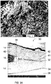
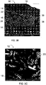
- 238000001000 micrograph Methods 0.000 description 4
- 238000007747 plating Methods 0.000 description 4
- 229920005629 polypropylene homopolymer Polymers 0.000 description 4
- 239000011148 porous material Substances 0.000 description 4
- 230000037303 wrinkles Effects 0.000 description 4
- VSKJLJHPAFKHBX-UHFFFAOYSA-N 2-methylbuta-1,3-diene;styrene Chemical compound CC(=C)C=C.C=CC1=CC=CC=C1.C=CC1=CC=CC=C1 VSKJLJHPAFKHBX-UHFFFAOYSA-N 0.000 description 3
- NLHHRLWOUZZQLW-UHFFFAOYSA-N Acrylonitrile Chemical compound C=CC#N NLHHRLWOUZZQLW-UHFFFAOYSA-N 0.000 description 3
- LYCAIKOWRPUZTN-UHFFFAOYSA-N Ethylene glycol Chemical compound OCCO LYCAIKOWRPUZTN-UHFFFAOYSA-N 0.000 description 3
- RRHGJUQNOFWUDK-UHFFFAOYSA-N Isoprene Chemical compound CC(=C)C=C RRHGJUQNOFWUDK-UHFFFAOYSA-N 0.000 description 3
- 229920000388 Polyphosphate Polymers 0.000 description 3
- DNIAPMSPPWPWGF-UHFFFAOYSA-N Propylene glycol Chemical compound CC(O)CO DNIAPMSPPWPWGF-UHFFFAOYSA-N 0.000 description 3
- XTXRWKRVRITETP-UHFFFAOYSA-N Vinyl acetate Chemical compound CC(=O)OC=C XTXRWKRVRITETP-UHFFFAOYSA-N 0.000 description 3
- 238000005219 brazing Methods 0.000 description 3
- FACXGONDLDSNOE-UHFFFAOYSA-N buta-1,3-diene;styrene Chemical compound C=CC=C.C=CC1=CC=CC=C1.C=CC1=CC=CC=C1 FACXGONDLDSNOE-UHFFFAOYSA-N 0.000 description 3
- 229910000019 calcium carbonate Inorganic materials 0.000 description 3
- 230000001413 cellular effect Effects 0.000 description 3
- 239000007795 chemical reaction product Substances 0.000 description 3
- 239000011651 chromium Substances 0.000 description 3
- 239000011231 conductive filler Substances 0.000 description 3
- 238000010924 continuous production Methods 0.000 description 3
- 150000004985 diamines Chemical class 0.000 description 3
- 238000000113 differential scanning calorimetry Methods 0.000 description 3
- 239000008187 granular material Substances 0.000 description 3
- 229920001519 homopolymer Polymers 0.000 description 3
- 150000003949 imides Chemical class 0.000 description 3
- VAKIVKMUBMZANL-UHFFFAOYSA-N iron phosphide Chemical compound P.[Fe].[Fe].[Fe] VAKIVKMUBMZANL-UHFFFAOYSA-N 0.000 description 3
- VTHJTEIRLNZDEV-UHFFFAOYSA-L magnesium dihydroxide Chemical compound [OH-].[OH-].[Mg+2] VTHJTEIRLNZDEV-UHFFFAOYSA-L 0.000 description 3
- 239000000347 magnesium hydroxide Substances 0.000 description 3
- 229910001862 magnesium hydroxide Inorganic materials 0.000 description 3
- FPYJFEHAWHCUMM-UHFFFAOYSA-N maleic anhydride Chemical compound O=C1OC(=O)C=C1 FPYJFEHAWHCUMM-UHFFFAOYSA-N 0.000 description 3
- 239000000155 melt Substances 0.000 description 3
- 239000012802 nanoclay Substances 0.000 description 3
- 229910052759 nickel Inorganic materials 0.000 description 3
- 239000008188 pellet Substances 0.000 description 3
- 230000000737 periodic effect Effects 0.000 description 3
- 229920003023 plastic Polymers 0.000 description 3
- 239000004033 plastic Substances 0.000 description 3
- 229920000553 poly(phenylenevinylene) Polymers 0.000 description 3
- 238000006116 polymerization reaction Methods 0.000 description 3
- 239000001205 polyphosphate Substances 0.000 description 3
- 235000011176 polyphosphates Nutrition 0.000 description 3
- 229920005604 random copolymer Polymers 0.000 description 3
- 229920000638 styrene acrylonitrile Polymers 0.000 description 3
- 229920000468 styrene butadiene styrene block copolymer Polymers 0.000 description 3
- 238000012360 testing method Methods 0.000 description 3
- 230000007704 transition Effects 0.000 description 3
- VYZAMTAEIAYCRO-UHFFFAOYSA-N Chromium Chemical compound [Cr] VYZAMTAEIAYCRO-UHFFFAOYSA-N 0.000 description 2
- 229920002943 EPDM rubber Polymers 0.000 description 2
- UQSXHKLRYXJYBZ-UHFFFAOYSA-N Iron oxide Chemical compound [Fe]=O UQSXHKLRYXJYBZ-UHFFFAOYSA-N 0.000 description 2
- 229920000305 Nylon 6,10 Polymers 0.000 description 2
- 229920000577 Nylon 6/66 Polymers 0.000 description 2
- NBIIXXVUZAFLBC-UHFFFAOYSA-N Phosphoric acid Chemical compound OP(O)(O)=O NBIIXXVUZAFLBC-UHFFFAOYSA-N 0.000 description 2
- KKEYFWRCBNTPAC-UHFFFAOYSA-N Terephthalic acid Chemical compound OC(=O)C1=CC=C(C(O)=O)C=C1 KKEYFWRCBNTPAC-UHFFFAOYSA-N 0.000 description 2
- YTPLMLYBLZKORZ-UHFFFAOYSA-N Thiophene Chemical compound C=1C=CSC=1 YTPLMLYBLZKORZ-UHFFFAOYSA-N 0.000 description 2
- WNLRTRBMVRJNCN-UHFFFAOYSA-N adipic acid Chemical compound OC(=O)CCCCC(O)=O WNLRTRBMVRJNCN-UHFFFAOYSA-N 0.000 description 2
- WNROFYMDJYEPJX-UHFFFAOYSA-K aluminium hydroxide Chemical compound [OH-].[OH-].[OH-].[Al+3] WNROFYMDJYEPJX-UHFFFAOYSA-K 0.000 description 2
- PNEYBMLMFCGWSK-UHFFFAOYSA-N aluminium oxide Inorganic materials [O-2].[O-2].[O-2].[Al+3].[Al+3] PNEYBMLMFCGWSK-UHFFFAOYSA-N 0.000 description 2
- 238000004458 analytical method Methods 0.000 description 2
- 229910001566 austenite Inorganic materials 0.000 description 2
- TZYHIGCKINZLPD-UHFFFAOYSA-N azepan-2-one;hexane-1,6-diamine;hexanedioic acid Chemical compound NCCCCCCN.O=C1CCCCCN1.OC(=O)CCCCC(O)=O TZYHIGCKINZLPD-UHFFFAOYSA-N 0.000 description 2
- 229910001563 bainite Inorganic materials 0.000 description 2
- 239000011324 bead Substances 0.000 description 2
- 238000009435 building construction Methods 0.000 description 2
- WERYXYBDKMZEQL-UHFFFAOYSA-N butane-1,4-diol Chemical compound OCCCCO WERYXYBDKMZEQL-UHFFFAOYSA-N 0.000 description 2
- OSGAYBCDTDRGGQ-UHFFFAOYSA-L calcium sulfate Chemical compound [Ca+2].[O-]S([O-])(=O)=O OSGAYBCDTDRGGQ-UHFFFAOYSA-L 0.000 description 2
- 230000015556 catabolic process Effects 0.000 description 2
- 210000004027 cell Anatomy 0.000 description 2
- 229910001567 cementite Inorganic materials 0.000 description 2
- 239000003795 chemical substances by application Substances 0.000 description 2
- 229910052804 chromium Inorganic materials 0.000 description 2
- 238000004140 cleaning Methods 0.000 description 2
- 230000006835 compression Effects 0.000 description 2
- 238000007906 compression Methods 0.000 description 2
- 229920001940 conductive polymer Polymers 0.000 description 2
- 238000006731 degradation reaction Methods 0.000 description 2
- 238000011161 development Methods 0.000 description 2
- 230000000694 effects Effects 0.000 description 2
- 230000005611 electricity Effects 0.000 description 2
- 230000001747 exhibiting effect Effects 0.000 description 2
- 239000011888 foil Substances 0.000 description 2
- 238000005242 forging Methods 0.000 description 2
- 230000004927 fusion Effects 0.000 description 2
- 150000002334 glycols Chemical class 0.000 description 2
- 238000000227 grinding Methods 0.000 description 2
- 150000002430 hydrocarbons Chemical class 0.000 description 2
- KSOKAHYVTMZFBJ-UHFFFAOYSA-N iron;methane Chemical compound C.[Fe].[Fe].[Fe] KSOKAHYVTMZFBJ-UHFFFAOYSA-N 0.000 description 2
- 239000011572 manganese Substances 0.000 description 2
- 229910052750 molybdenum Inorganic materials 0.000 description 2
- 239000000178 monomer Substances 0.000 description 2
- 229920003052 natural elastomer Polymers 0.000 description 2
- 229920001194 natural rubber Polymers 0.000 description 2
- 229910001562 pearlite Inorganic materials 0.000 description 2
- 238000005325 percolation Methods 0.000 description 2
- 235000011007 phosphoric acid Nutrition 0.000 description 2
- 229920000570 polyether Polymers 0.000 description 2
- 239000002861 polymer material Substances 0.000 description 2
- 229920000098 polyolefin Polymers 0.000 description 2
- 229920000123 polythiophene Polymers 0.000 description 2
- 238000004064 recycling Methods 0.000 description 2
- 230000009467 reduction Effects 0.000 description 2
- 238000012552 review Methods 0.000 description 2
- 229920006395 saturated elastomer Polymers 0.000 description 2
- 229920006126 semicrystalline polymer Polymers 0.000 description 2
- 238000005476 soldering Methods 0.000 description 2
- 239000007787 solid Substances 0.000 description 2
- 239000000126 substance Substances 0.000 description 2
- 229920001187 thermosetting polymer Polymers 0.000 description 2
- 229930192474 thiophene Natural products 0.000 description 2
- 206010048828 underweight Diseases 0.000 description 2
- 229910052720 vanadium Inorganic materials 0.000 description 2
- PUPZLCDOIYMWBV-UHFFFAOYSA-N (+/-)-1,3-Butanediol Chemical compound CC(O)CCO PUPZLCDOIYMWBV-UHFFFAOYSA-N 0.000 description 1
- YZEZMSPGIPTEBA-UHFFFAOYSA-N 2-n-(4,6-diamino-1,3,5-triazin-2-yl)-1,3,5-triazine-2,4,6-triamine Chemical compound NC1=NC(N)=NC(NC=2N=C(N)N=C(N)N=2)=N1 YZEZMSPGIPTEBA-UHFFFAOYSA-N 0.000 description 1
- 239000005995 Aluminium silicate Substances 0.000 description 1
- 229910052582 BN Inorganic materials 0.000 description 1
- PZNSFCLAULLKQX-UHFFFAOYSA-N Boron nitride Chemical compound N#B PZNSFCLAULLKQX-UHFFFAOYSA-N 0.000 description 1
- 229910001369 Brass Inorganic materials 0.000 description 1
- WKBOTKDWSSQWDR-UHFFFAOYSA-N Bromine atom Chemical compound [Br] WKBOTKDWSSQWDR-UHFFFAOYSA-N 0.000 description 1
- 229910000906 Bronze Inorganic materials 0.000 description 1
- UJOBWOGCFQCDNV-UHFFFAOYSA-N Carbazole Natural products C1=CC=C2C3=CC=CC=C3NC2=C1 UJOBWOGCFQCDNV-UHFFFAOYSA-N 0.000 description 1
- 229920000049 Carbon (fiber) Polymers 0.000 description 1
- 229910000975 Carbon steel Inorganic materials 0.000 description 1
- ZAMOUSCENKQFHK-UHFFFAOYSA-N Chlorine atom Chemical compound [Cl] ZAMOUSCENKQFHK-UHFFFAOYSA-N 0.000 description 1
- 229920000742 Cotton Polymers 0.000 description 1
- 244000241257 Cucumis melo Species 0.000 description 1
- 235000015510 Cucumis melo subsp melo Nutrition 0.000 description 1
- 229920001875 Ebonite Polymers 0.000 description 1
- LFQSCWFLJHTTHZ-UHFFFAOYSA-N Ethanol Chemical compound CCO LFQSCWFLJHTTHZ-UHFFFAOYSA-N 0.000 description 1
- CWYNVVGOOAEACU-UHFFFAOYSA-N Fe2+ Chemical compound [Fe+2] CWYNVVGOOAEACU-UHFFFAOYSA-N 0.000 description 1
- 244000043261 Hevea brasiliensis Species 0.000 description 1
- 239000006237 Intermediate SAF Substances 0.000 description 1
- 239000005909 Kieselgur Substances 0.000 description 1
- PWHULOQIROXLJO-UHFFFAOYSA-N Manganese Chemical compound [Mn] PWHULOQIROXLJO-UHFFFAOYSA-N 0.000 description 1
- 229920000877 Melamine resin Polymers 0.000 description 1
- ZOKXTWBITQBERF-UHFFFAOYSA-N Molybdenum Chemical compound [Mo] ZOKXTWBITQBERF-UHFFFAOYSA-N 0.000 description 1
- 239000006057 Non-nutritive feed additive Substances 0.000 description 1
- 229920000571 Nylon 11 Polymers 0.000 description 1
- 229920003188 Nylon 3 Polymers 0.000 description 1
- 229920001007 Nylon 4 Polymers 0.000 description 1
- 229920000572 Nylon 6/12 Polymers 0.000 description 1
- MXRIRQGCELJRSN-UHFFFAOYSA-N O.O.O.[Al] Chemical compound O.O.O.[Al] MXRIRQGCELJRSN-UHFFFAOYSA-N 0.000 description 1
- BPQQTUXANYXVAA-UHFFFAOYSA-N Orthosilicate Chemical compound [O-][Si]([O-])([O-])[O-] BPQQTUXANYXVAA-UHFFFAOYSA-N 0.000 description 1
- 229910019142 PO4 Inorganic materials 0.000 description 1
- OAICVXFJPJFONN-UHFFFAOYSA-N Phosphorus Chemical compound [P] OAICVXFJPJFONN-UHFFFAOYSA-N 0.000 description 1
- 229920000280 Poly(3-octylthiophene) Polymers 0.000 description 1
- 239000004721 Polyphenylene oxide Substances 0.000 description 1
- 102000014961 Protein Precursors Human genes 0.000 description 1
- 108010078762 Protein Precursors Proteins 0.000 description 1
- GWEVSGVZZGPLCZ-UHFFFAOYSA-N Titan oxide Chemical compound O=[Ti]=O GWEVSGVZZGPLCZ-UHFFFAOYSA-N 0.000 description 1
- 229910021536 Zeolite Inorganic materials 0.000 description 1
- HCHKCACWOHOZIP-UHFFFAOYSA-N Zinc Chemical compound [Zn] HCHKCACWOHOZIP-UHFFFAOYSA-N 0.000 description 1
- FJJCIZWZNKZHII-UHFFFAOYSA-N [4,6-bis(cyanoamino)-1,3,5-triazin-2-yl]cyanamide Chemical compound N#CNC1=NC(NC#N)=NC(NC#N)=N1 FJJCIZWZNKZHII-UHFFFAOYSA-N 0.000 description 1
- 239000002253 acid Substances 0.000 description 1
- 150000007513 acids Chemical class 0.000 description 1
- 208000013685 acquired idiopathic sideroblastic anemia Diseases 0.000 description 1
- 150000001252 acrylic acid derivatives Chemical class 0.000 description 1
- 150000001253 acrylic acids Chemical class 0.000 description 1
- 230000001154 acute effect Effects 0.000 description 1
- 239000002318 adhesion promoter Substances 0.000 description 1
- 239000001361 adipic acid Substances 0.000 description 1
- 235000011037 adipic acid Nutrition 0.000 description 1
- 229910021502 aluminium hydroxide Inorganic materials 0.000 description 1
- 229910000147 aluminium phosphate Inorganic materials 0.000 description 1
- 235000012211 aluminium silicate Nutrition 0.000 description 1
- 150000001412 amines Chemical class 0.000 description 1
- 238000000137 annealing Methods 0.000 description 1
- 229910052787 antimony Inorganic materials 0.000 description 1
- WATWJIUSRGPENY-UHFFFAOYSA-N antimony atom Chemical compound [Sb] WATWJIUSRGPENY-UHFFFAOYSA-N 0.000 description 1
- 229910000410 antimony oxide Inorganic materials 0.000 description 1
- 239000003963 antioxidant agent Substances 0.000 description 1
- 239000002216 antistatic agent Substances 0.000 description 1
- 238000010923 batch production Methods 0.000 description 1
- 230000003542 behavioural effect Effects 0.000 description 1
- 230000009286 beneficial effect Effects 0.000 description 1
- 230000008901 benefit Effects 0.000 description 1
- 239000000440 bentonite Substances 0.000 description 1
- 229910000278 bentonite Inorganic materials 0.000 description 1
- SVPXDRXYRYOSEX-UHFFFAOYSA-N bentoquatam Chemical compound O.O=[Si]=O.O=[Al]O[Al]=O SVPXDRXYRYOSEX-UHFFFAOYSA-N 0.000 description 1
- PASDCCFISLVPSO-UHFFFAOYSA-N benzoyl chloride Chemical class ClC(=O)C1=CC=CC=C1 PASDCCFISLVPSO-UHFFFAOYSA-N 0.000 description 1
- 239000010951 brass Substances 0.000 description 1
- GDTBXPJZTBHREO-UHFFFAOYSA-N bromine Substances BrBr GDTBXPJZTBHREO-UHFFFAOYSA-N 0.000 description 1
- 229910052794 bromium Inorganic materials 0.000 description 1
- 239000010974 bronze Substances 0.000 description 1
- 239000001273 butane Substances 0.000 description 1
- AXCZMVOFGPJBDE-UHFFFAOYSA-L calcium dihydroxide Chemical compound [OH-].[OH-].[Ca+2] AXCZMVOFGPJBDE-UHFFFAOYSA-L 0.000 description 1
- 239000000920 calcium hydroxide Substances 0.000 description 1
- 229910001861 calcium hydroxide Inorganic materials 0.000 description 1
- 239000000378 calcium silicate Substances 0.000 description 1
- 229910052918 calcium silicate Inorganic materials 0.000 description 1
- OYACROKNLOSFPA-UHFFFAOYSA-N calcium;dioxido(oxo)silane Chemical compound [Ca+2].[O-][Si]([O-])=O OYACROKNLOSFPA-UHFFFAOYSA-N 0.000 description 1
- 238000003490 calendering Methods 0.000 description 1
- 239000004917 carbon fiber Substances 0.000 description 1
- 150000001732 carboxylic acid derivatives Chemical class 0.000 description 1
- 238000005266 casting Methods 0.000 description 1
- 210000002421 cell wall Anatomy 0.000 description 1
- 239000000460 chlorine Substances 0.000 description 1
- 229910052801 chlorine Inorganic materials 0.000 description 1
- 239000004927 clay Substances 0.000 description 1
- 229910052570 clay Inorganic materials 0.000 description 1
- 238000013329 compounding Methods 0.000 description 1
- 150000001875 compounds Chemical class 0.000 description 1
- 239000004020 conductor Substances 0.000 description 1
- 238000010276 construction Methods 0.000 description 1
- 239000004035 construction material Substances 0.000 description 1
- 238000011109 contamination Methods 0.000 description 1
- 238000007334 copolymerization reaction Methods 0.000 description 1
- KUNSUQLRTQLHQQ-UHFFFAOYSA-N copper tin Chemical compound [Cu].[Sn] KUNSUQLRTQLHQQ-UHFFFAOYSA-N 0.000 description 1
- 239000007799 cork Substances 0.000 description 1
- 239000007822 coupling agent Substances 0.000 description 1
- 238000005336 cracking Methods 0.000 description 1
- 238000002788 crimping Methods 0.000 description 1
- 239000013078 crystal Substances 0.000 description 1
- 230000001351 cycling effect Effects 0.000 description 1
- 230000003247 decreasing effect Effects 0.000 description 1
- 238000009795 derivation Methods 0.000 description 1
- GDVKFRBCXAPAQJ-UHFFFAOYSA-A dialuminum;hexamagnesium;carbonate;hexadecahydroxide Chemical compound [OH-].[OH-].[OH-].[OH-].[OH-].[OH-].[OH-].[OH-].[OH-].[OH-].[OH-].[OH-].[OH-].[OH-].[OH-].[OH-].[Mg+2].[Mg+2].[Mg+2].[Mg+2].[Mg+2].[Mg+2].[Al+3].[Al+3].[O-]C([O-])=O GDVKFRBCXAPAQJ-UHFFFAOYSA-A 0.000 description 1
- 238000007865 diluting Methods 0.000 description 1
- HNPSIPDUKPIQMN-UHFFFAOYSA-N dioxosilane;oxo(oxoalumanyloxy)alumane Chemical compound O=[Si]=O.O=[Al]O[Al]=O HNPSIPDUKPIQMN-UHFFFAOYSA-N 0.000 description 1
- 238000007598 dipping method Methods 0.000 description 1
- 239000010459 dolomite Substances 0.000 description 1
- 229910000514 dolomite Inorganic materials 0.000 description 1
- 238000001035 drying Methods 0.000 description 1
- 238000004070 electrodeposition Methods 0.000 description 1
- 238000010894 electron beam technology Methods 0.000 description 1
- 238000009503 electrostatic coating Methods 0.000 description 1
- 150000002118 epoxides Chemical class 0.000 description 1
- QFXZANXYUCUTQH-UHFFFAOYSA-N ethynol Chemical group OC#C QFXZANXYUCUTQH-UHFFFAOYSA-N 0.000 description 1
- 210000003195 fascia Anatomy 0.000 description 1
- 239000012765 fibrous filler Substances 0.000 description 1
- 239000002657 fibrous material Substances 0.000 description 1
- 244000144992 flock Species 0.000 description 1
- 238000009408 flooring Methods 0.000 description 1
- 239000004088 foaming agent Substances 0.000 description 1
- 238000009432 framing Methods 0.000 description 1
- 125000000524 functional group Chemical group 0.000 description 1
- 229910001679 gibbsite Inorganic materials 0.000 description 1
- 239000011521 glass Substances 0.000 description 1
- PCHJSUWPFVWCPO-UHFFFAOYSA-N gold Chemical compound [Au] PCHJSUWPFVWCPO-UHFFFAOYSA-N 0.000 description 1
- 229910052737 gold Inorganic materials 0.000 description 1
- 239000010931 gold Substances 0.000 description 1
- 229920000578 graft copolymer Polymers 0.000 description 1
- 229920001112 grafted polyolefin Polymers 0.000 description 1
- 229910052736 halogen Inorganic materials 0.000 description 1
- 150000002367 halogens Chemical class 0.000 description 1
- 229920001903 high density polyethylene Polymers 0.000 description 1
- 239000004700 high-density polyethylene Substances 0.000 description 1
- 229910001701 hydrotalcite Inorganic materials 0.000 description 1
- 229960001545 hydrotalcite Drugs 0.000 description 1
- 238000010348 incorporation Methods 0.000 description 1
- 239000011261 inert gas Substances 0.000 description 1
- 238000007641 inkjet printing Methods 0.000 description 1
- 239000012212 insulator Substances 0.000 description 1
- 239000011229 interlayer Substances 0.000 description 1
- NLYAJNPCOHFWQQ-UHFFFAOYSA-N kaolin Chemical compound O.O.O=[Al]O[Si](=O)O[Si](=O)O[Al]=O NLYAJNPCOHFWQQ-UHFFFAOYSA-N 0.000 description 1
- 238000003475 lamination Methods 0.000 description 1
- 239000007788 liquid Substances 0.000 description 1
- 238000001459 lithography Methods 0.000 description 1
- 238000011068 loading method Methods 0.000 description 1
- 239000000314 lubricant Substances 0.000 description 1
- 238000003754 machining Methods 0.000 description 1
- 229920002521 macromolecule Polymers 0.000 description 1
- ZLNQQNXFFQJAID-UHFFFAOYSA-L magnesium carbonate Chemical compound [Mg+2].[O-]C([O-])=O ZLNQQNXFFQJAID-UHFFFAOYSA-L 0.000 description 1
- 239000001095 magnesium carbonate Substances 0.000 description 1
- 229910000021 magnesium carbonate Inorganic materials 0.000 description 1
- 239000000395 magnesium oxide Substances 0.000 description 1
- CPLXHLVBOLITMK-UHFFFAOYSA-N magnesium oxide Inorganic materials [Mg]=O CPLXHLVBOLITMK-UHFFFAOYSA-N 0.000 description 1
- AXZKOIWUVFPNLO-UHFFFAOYSA-N magnesium;oxygen(2-) Chemical compound [O-2].[Mg+2] AXZKOIWUVFPNLO-UHFFFAOYSA-N 0.000 description 1
- 229910052748 manganese Inorganic materials 0.000 description 1
- 229910000734 martensite Inorganic materials 0.000 description 1
- 230000007246 mechanism Effects 0.000 description 1
- JDSHMPZPIAZGSV-UHFFFAOYSA-N melamine Chemical compound NC1=NC(N)=NC(N)=N1 JDSHMPZPIAZGSV-UHFFFAOYSA-N 0.000 description 1
- ZQKXQUJXLSSJCH-UHFFFAOYSA-N melamine cyanurate Chemical compound NC1=NC(N)=NC(N)=N1.O=C1NC(=O)NC(=O)N1 ZQKXQUJXLSSJCH-UHFFFAOYSA-N 0.000 description 1
- YSRVJVDFHZYRPA-UHFFFAOYSA-N melem Chemical compound NC1=NC(N23)=NC(N)=NC2=NC(N)=NC3=N1 YSRVJVDFHZYRPA-UHFFFAOYSA-N 0.000 description 1
- 239000002905 metal composite material Substances 0.000 description 1
- 239000002923 metal particle Substances 0.000 description 1
- 238000005555 metalworking Methods 0.000 description 1
- 239000010445 mica Substances 0.000 description 1
- 229910052618 mica group Inorganic materials 0.000 description 1
- 238000000386 microscopy Methods 0.000 description 1
- 238000012986 modification Methods 0.000 description 1
- 230000004048 modification Effects 0.000 description 1
- 239000011733 molybdenum Substances 0.000 description 1
- 238000000465 moulding Methods 0.000 description 1
- 238000009740 moulding (composite fabrication) Methods 0.000 description 1
- IJDNQMDRQITEOD-UHFFFAOYSA-N n-butane Chemical compound CCCC IJDNQMDRQITEOD-UHFFFAOYSA-N 0.000 description 1
- OFBQJSOFQDEBGM-UHFFFAOYSA-N n-pentane Natural products CCCCC OFBQJSOFQDEBGM-UHFFFAOYSA-N 0.000 description 1
- 239000002071 nanotube Substances 0.000 description 1
- QJGQUHMNIGDVPM-UHFFFAOYSA-N nitrogen group Chemical group [N] QJGQUHMNIGDVPM-UHFFFAOYSA-N 0.000 description 1
- 229910052755 nonmetal Inorganic materials 0.000 description 1
- 150000002843 nonmetals Chemical class 0.000 description 1
- 239000003921 oil Substances 0.000 description 1
- VTRUBDSFZJNXHI-UHFFFAOYSA-N oxoantimony Chemical compound [Sb]=O VTRUBDSFZJNXHI-UHFFFAOYSA-N 0.000 description 1
- RVTZCBVAJQQJTK-UHFFFAOYSA-N oxygen(2-);zirconium(4+) Chemical compound [O-2].[O-2].[Zr+4] RVTZCBVAJQQJTK-UHFFFAOYSA-N 0.000 description 1
- 239000003973 paint Substances 0.000 description 1
- 235000021317 phosphate Nutrition 0.000 description 1
- 150000008301 phosphite esters Chemical class 0.000 description 1
- 150000003013 phosphoric acid derivatives Chemical class 0.000 description 1
- XFZRQAZGUOTJCS-UHFFFAOYSA-N phosphoric acid;1,3,5-triazine-2,4,6-triamine Chemical compound OP(O)(O)=O.NC1=NC(N)=NC(N)=N1 XFZRQAZGUOTJCS-UHFFFAOYSA-N 0.000 description 1
- 150000003016 phosphoric acids Chemical class 0.000 description 1
- 229910052698 phosphorus Inorganic materials 0.000 description 1
- 239000011574 phosphorus Substances 0.000 description 1
- 238000000206 photolithography Methods 0.000 description 1
- 239000000049 pigment Substances 0.000 description 1
- 238000009428 plumbing Methods 0.000 description 1
- 229920003190 poly( p-benzamide) Polymers 0.000 description 1
- 229920002805 poly(2,2'-bithiophene-5,5'-diyl) polymer Polymers 0.000 description 1
- 229920006111 poly(hexamethylene terephthalamide) Polymers 0.000 description 1
- 229920000767 polyaniline Polymers 0.000 description 1
- 229920000329 polyazepine Polymers 0.000 description 1
- 229920000323 polyazulene Polymers 0.000 description 1
- 229920001707 polybutylene terephthalate Polymers 0.000 description 1
- 229920001088 polycarbazole Polymers 0.000 description 1
- 229920005638 polyethylene monopolymer Polymers 0.000 description 1
- 229920000139 polyethylene terephthalate Polymers 0.000 description 1
- 229920002098 polyfluorene Polymers 0.000 description 1
- 229920001195 polyisoprene Polymers 0.000 description 1
- 230000000379 polymerizing effect Effects 0.000 description 1
- 229920000417 polynaphthalene Polymers 0.000 description 1
- 229920000069 polyphenylene sulfide Polymers 0.000 description 1
- 238000001556 precipitation Methods 0.000 description 1
- 238000007639 printing Methods 0.000 description 1
- 230000002250 progressing effect Effects 0.000 description 1
- SCUZVMOVTVSBLE-UHFFFAOYSA-N prop-2-enenitrile;styrene Chemical compound C=CC#N.C=CC1=CC=CC=C1 SCUZVMOVTVSBLE-UHFFFAOYSA-N 0.000 description 1
- 239000008262 pumice Substances 0.000 description 1
- 238000004080 punching Methods 0.000 description 1
- 229910052903 pyrophyllite Inorganic materials 0.000 description 1
- 230000002787 reinforcement Effects 0.000 description 1
- 239000005060 rubber Substances 0.000 description 1
- 238000007665 sagging Methods 0.000 description 1
- 150000003839 salts Chemical class 0.000 description 1
- 238000000926 separation method Methods 0.000 description 1
- 238000007778 shielded metal arc welding Methods 0.000 description 1
- 229910052710 silicon Inorganic materials 0.000 description 1
- 239000010703 silicon Substances 0.000 description 1
- HBMJWWWQQXIZIP-UHFFFAOYSA-N silicon carbide Chemical compound [Si+]#[C-] HBMJWWWQQXIZIP-UHFFFAOYSA-N 0.000 description 1
- 229910010271 silicon carbide Inorganic materials 0.000 description 1
- 239000000377 silicon dioxide Substances 0.000 description 1
- 229910052814 silicon oxide Inorganic materials 0.000 description 1
- 239000002356 single layer Substances 0.000 description 1
- 238000000638 solvent extraction Methods 0.000 description 1
- 239000012798 spherical particle Substances 0.000 description 1
- 238000005507 spraying Methods 0.000 description 1
- 239000003381 stabilizer Substances 0.000 description 1
- 238000003860 storage Methods 0.000 description 1
- 238000005728 strengthening Methods 0.000 description 1
- 229920006132 styrene block copolymer Polymers 0.000 description 1
- 238000004381 surface treatment Methods 0.000 description 1
- 229920003051 synthetic elastomer Polymers 0.000 description 1
- 239000000454 talc Substances 0.000 description 1
- 229910052623 talc Inorganic materials 0.000 description 1
- 238000010998 test method Methods 0.000 description 1
- 238000007669 thermal treatment Methods 0.000 description 1
- 239000010409 thin film Substances 0.000 description 1
- 150000003577 thiophenes Chemical class 0.000 description 1
- OGIDPMRJRNCKJF-UHFFFAOYSA-N titanium oxide Inorganic materials [Ti]=O OGIDPMRJRNCKJF-UHFFFAOYSA-N 0.000 description 1
- 238000009966 trimming Methods 0.000 description 1
- WFKWXMTUELFFGS-UHFFFAOYSA-N tungsten Chemical compound [W] WFKWXMTUELFFGS-UHFFFAOYSA-N 0.000 description 1
- 229910052721 tungsten Inorganic materials 0.000 description 1
- 239000010937 tungsten Substances 0.000 description 1
- 238000007514 turning Methods 0.000 description 1
- GPPXJZIENCGNKB-UHFFFAOYSA-N vanadium Chemical compound [V]#[V] GPPXJZIENCGNKB-UHFFFAOYSA-N 0.000 description 1
- 239000003190 viscoelastic substance Substances 0.000 description 1
- 239000010456 wollastonite Substances 0.000 description 1
- 229910052882 wollastonite Inorganic materials 0.000 description 1
- 239000002023 wood Substances 0.000 description 1
- 239000010457 zeolite Substances 0.000 description 1
- 229910052725 zinc Inorganic materials 0.000 description 1
- 239000011701 zinc Substances 0.000 description 1
- DXZMANYCMVCPIM-UHFFFAOYSA-L zinc;diethylphosphinate Chemical compound [Zn+2].CCP([O-])(=O)CC.CCP([O-])(=O)CC DXZMANYCMVCPIM-UHFFFAOYSA-L 0.000 description 1
- 229910001928 zirconium oxide Inorganic materials 0.000 description 1
- 239000004711 α-olefin Substances 0.000 description 1
Images

Classifications
-
- B—PERFORMING OPERATIONS; TRANSPORTING
- B32—LAYERED PRODUCTS
- B32B—LAYERED PRODUCTS, i.e. PRODUCTS BUILT-UP OF STRATA OF FLAT OR NON-FLAT, e.g. CELLULAR OR HONEYCOMB, FORM
- B32B15/00—Layered products comprising a layer of metal
- B32B15/04—Layered products comprising a layer of metal comprising metal as the main or only constituent of a layer, which is next to another layer of the same or of a different material
- B32B15/08—Layered products comprising a layer of metal comprising metal as the main or only constituent of a layer, which is next to another layer of the same or of a different material of synthetic resin
-
- B—PERFORMING OPERATIONS; TRANSPORTING
- B23—MACHINE TOOLS; METAL-WORKING NOT OTHERWISE PROVIDED FOR
- B23K—SOLDERING OR UNSOLDERING; WELDING; CLADDING OR PLATING BY SOLDERING OR WELDING; CUTTING BY APPLYING HEAT LOCALLY, e.g. FLAME CUTTING; WORKING BY LASER BEAM
- B23K11/00—Resistance welding; Severing by resistance heating
- B23K11/10—Spot welding; Stitch welding
- B23K11/11—Spot welding
-
- B—PERFORMING OPERATIONS; TRANSPORTING
- B23—MACHINE TOOLS; METAL-WORKING NOT OTHERWISE PROVIDED FOR
- B23K—SOLDERING OR UNSOLDERING; WELDING; CLADDING OR PLATING BY SOLDERING OR WELDING; CUTTING BY APPLYING HEAT LOCALLY, e.g. FLAME CUTTING; WORKING BY LASER BEAM
- B23K11/00—Resistance welding; Severing by resistance heating
- B23K11/16—Resistance welding; Severing by resistance heating taking account of the properties of the material to be welded
-
- B—PERFORMING OPERATIONS; TRANSPORTING
- B29—WORKING OF PLASTICS; WORKING OF SUBSTANCES IN A PLASTIC STATE IN GENERAL
- B29B—PREPARATION OR PRETREATMENT OF THE MATERIAL TO BE SHAPED; MAKING GRANULES OR PREFORMS; RECOVERY OF PLASTICS OR OTHER CONSTITUENTS OF WASTE MATERIAL CONTAINING PLASTICS
- B29B9/00—Making granules
- B29B9/12—Making granules characterised by structure or composition
-
- B—PERFORMING OPERATIONS; TRANSPORTING
- B29—WORKING OF PLASTICS; WORKING OF SUBSTANCES IN A PLASTIC STATE IN GENERAL
- B29C—SHAPING OR JOINING OF PLASTICS; SHAPING OF MATERIAL IN A PLASTIC STATE, NOT OTHERWISE PROVIDED FOR; AFTER-TREATMENT OF THE SHAPED PRODUCTS, e.g. REPAIRING
- B29C70/00—Shaping composites, i.e. plastics material comprising reinforcements, fillers or preformed parts, e.g. inserts
- B29C70/02—Shaping composites, i.e. plastics material comprising reinforcements, fillers or preformed parts, e.g. inserts comprising combinations of reinforcements, e.g. non-specified reinforcements, fibrous reinforcing inserts and fillers, e.g. particulate fillers, incorporated in matrix material, forming one or more layers and with or without non-reinforced or non-filled layers
- B29C70/021—Combinations of fibrous reinforcement and non-fibrous material
- B29C70/025—Combinations of fibrous reinforcement and non-fibrous material with particular filler
-
- B—PERFORMING OPERATIONS; TRANSPORTING
- B29—WORKING OF PLASTICS; WORKING OF SUBSTANCES IN A PLASTIC STATE IN GENERAL
- B29C—SHAPING OR JOINING OF PLASTICS; SHAPING OF MATERIAL IN A PLASTIC STATE, NOT OTHERWISE PROVIDED FOR; AFTER-TREATMENT OF THE SHAPED PRODUCTS, e.g. REPAIRING
- B29C70/00—Shaping composites, i.e. plastics material comprising reinforcements, fillers or preformed parts, e.g. inserts
- B29C70/02—Shaping composites, i.e. plastics material comprising reinforcements, fillers or preformed parts, e.g. inserts comprising combinations of reinforcements, e.g. non-specified reinforcements, fibrous reinforcing inserts and fillers, e.g. particulate fillers, incorporated in matrix material, forming one or more layers and with or without non-reinforced or non-filled layers
- B29C70/028—Shaping composites, i.e. plastics material comprising reinforcements, fillers or preformed parts, e.g. inserts comprising combinations of reinforcements, e.g. non-specified reinforcements, fibrous reinforcing inserts and fillers, e.g. particulate fillers, incorporated in matrix material, forming one or more layers and with or without non-reinforced or non-filled layers and with one or more layers of non-plastics material or non-specified material, e.g. supports
-
- B—PERFORMING OPERATIONS; TRANSPORTING
- B29—WORKING OF PLASTICS; WORKING OF SUBSTANCES IN A PLASTIC STATE IN GENERAL
- B29C—SHAPING OR JOINING OF PLASTICS; SHAPING OF MATERIAL IN A PLASTIC STATE, NOT OTHERWISE PROVIDED FOR; AFTER-TREATMENT OF THE SHAPED PRODUCTS, e.g. REPAIRING
- B29C70/00—Shaping composites, i.e. plastics material comprising reinforcements, fillers or preformed parts, e.g. inserts
- B29C70/04—Shaping composites, i.e. plastics material comprising reinforcements, fillers or preformed parts, e.g. inserts comprising reinforcements only, e.g. self-reinforcing plastics
- B29C70/06—Fibrous reinforcements only
- B29C70/08—Fibrous reinforcements only comprising combinations of different forms of fibrous reinforcements incorporated in matrix material, forming one or more layers, and with or without non-reinforced layers
- B29C70/088—Fibrous reinforcements only comprising combinations of different forms of fibrous reinforcements incorporated in matrix material, forming one or more layers, and with or without non-reinforced layers and with one or more layers of non-plastics material or non-specified material, e.g. supports
-
- B—PERFORMING OPERATIONS; TRANSPORTING
- B32—LAYERED PRODUCTS
- B32B—LAYERED PRODUCTS, i.e. PRODUCTS BUILT-UP OF STRATA OF FLAT OR NON-FLAT, e.g. CELLULAR OR HONEYCOMB, FORM
- B32B15/00—Layered products comprising a layer of metal
- B32B15/01—Layered products comprising a layer of metal all layers being exclusively metallic
- B32B15/013—Layered products comprising a layer of metal all layers being exclusively metallic one layer being formed of an iron alloy or steel, another layer being formed of a metal other than iron or aluminium
-
- B—PERFORMING OPERATIONS; TRANSPORTING
- B32—LAYERED PRODUCTS
- B32B—LAYERED PRODUCTS, i.e. PRODUCTS BUILT-UP OF STRATA OF FLAT OR NON-FLAT, e.g. CELLULAR OR HONEYCOMB, FORM
- B32B15/00—Layered products comprising a layer of metal
- B32B15/04—Layered products comprising a layer of metal comprising metal as the main or only constituent of a layer, which is next to another layer of the same or of a different material
- B32B15/043—Layered products comprising a layer of metal comprising metal as the main or only constituent of a layer, which is next to another layer of the same or of a different material of metal
-
- B—PERFORMING OPERATIONS; TRANSPORTING
- B32—LAYERED PRODUCTS
- B32B—LAYERED PRODUCTS, i.e. PRODUCTS BUILT-UP OF STRATA OF FLAT OR NON-FLAT, e.g. CELLULAR OR HONEYCOMB, FORM
- B32B15/00—Layered products comprising a layer of metal
- B32B15/04—Layered products comprising a layer of metal comprising metal as the main or only constituent of a layer, which is next to another layer of the same or of a different material
- B32B15/08—Layered products comprising a layer of metal comprising metal as the main or only constituent of a layer, which is next to another layer of the same or of a different material of synthetic resin
- B32B15/082—Layered products comprising a layer of metal comprising metal as the main or only constituent of a layer, which is next to another layer of the same or of a different material of synthetic resin comprising vinyl resins; comprising acrylic resins
-
- B—PERFORMING OPERATIONS; TRANSPORTING
- B32—LAYERED PRODUCTS
- B32B—LAYERED PRODUCTS, i.e. PRODUCTS BUILT-UP OF STRATA OF FLAT OR NON-FLAT, e.g. CELLULAR OR HONEYCOMB, FORM
- B32B15/00—Layered products comprising a layer of metal
- B32B15/04—Layered products comprising a layer of metal comprising metal as the main or only constituent of a layer, which is next to another layer of the same or of a different material
- B32B15/08—Layered products comprising a layer of metal comprising metal as the main or only constituent of a layer, which is next to another layer of the same or of a different material of synthetic resin
- B32B15/085—Layered products comprising a layer of metal comprising metal as the main or only constituent of a layer, which is next to another layer of the same or of a different material of synthetic resin comprising polyolefins
-
- B—PERFORMING OPERATIONS; TRANSPORTING
- B32—LAYERED PRODUCTS
- B32B—LAYERED PRODUCTS, i.e. PRODUCTS BUILT-UP OF STRATA OF FLAT OR NON-FLAT, e.g. CELLULAR OR HONEYCOMB, FORM
- B32B15/00—Layered products comprising a layer of metal
- B32B15/18—Layered products comprising a layer of metal comprising iron or steel
-
- B—PERFORMING OPERATIONS; TRANSPORTING
- B32—LAYERED PRODUCTS
- B32B—LAYERED PRODUCTS, i.e. PRODUCTS BUILT-UP OF STRATA OF FLAT OR NON-FLAT, e.g. CELLULAR OR HONEYCOMB, FORM
- B32B15/00—Layered products comprising a layer of metal
- B32B15/20—Layered products comprising a layer of metal comprising aluminium or copper
-
- B—PERFORMING OPERATIONS; TRANSPORTING
- B32—LAYERED PRODUCTS
- B32B—LAYERED PRODUCTS, i.e. PRODUCTS BUILT-UP OF STRATA OF FLAT OR NON-FLAT, e.g. CELLULAR OR HONEYCOMB, FORM
- B32B27/00—Layered products comprising a layer of synthetic resin
- B32B27/28—Layered products comprising a layer of synthetic resin comprising synthetic resins not wholly covered by any one of the sub-groups B32B27/30 - B32B27/42
- B32B27/281—Layered products comprising a layer of synthetic resin comprising synthetic resins not wholly covered by any one of the sub-groups B32B27/30 - B32B27/42 comprising polyimides
-
- B—PERFORMING OPERATIONS; TRANSPORTING
- B32—LAYERED PRODUCTS
- B32B—LAYERED PRODUCTS, i.e. PRODUCTS BUILT-UP OF STRATA OF FLAT OR NON-FLAT, e.g. CELLULAR OR HONEYCOMB, FORM
- B32B27/00—Layered products comprising a layer of synthetic resin
- B32B27/30—Layered products comprising a layer of synthetic resin comprising vinyl (co)polymers; comprising acrylic (co)polymers
-
- B—PERFORMING OPERATIONS; TRANSPORTING
- B32—LAYERED PRODUCTS
- B32B—LAYERED PRODUCTS, i.e. PRODUCTS BUILT-UP OF STRATA OF FLAT OR NON-FLAT, e.g. CELLULAR OR HONEYCOMB, FORM
- B32B27/00—Layered products comprising a layer of synthetic resin
- B32B27/32—Layered products comprising a layer of synthetic resin comprising polyolefins
-
- B—PERFORMING OPERATIONS; TRANSPORTING
- B32—LAYERED PRODUCTS
- B32B—LAYERED PRODUCTS, i.e. PRODUCTS BUILT-UP OF STRATA OF FLAT OR NON-FLAT, e.g. CELLULAR OR HONEYCOMB, FORM
- B32B27/00—Layered products comprising a layer of synthetic resin
- B32B27/34—Layered products comprising a layer of synthetic resin comprising polyamides
-
- B—PERFORMING OPERATIONS; TRANSPORTING
- B32—LAYERED PRODUCTS
- B32B—LAYERED PRODUCTS, i.e. PRODUCTS BUILT-UP OF STRATA OF FLAT OR NON-FLAT, e.g. CELLULAR OR HONEYCOMB, FORM
- B32B27/00—Layered products comprising a layer of synthetic resin
- B32B27/36—Layered products comprising a layer of synthetic resin comprising polyesters
- B32B27/365—Layered products comprising a layer of synthetic resin comprising polyesters comprising polycarbonates
-
- B—PERFORMING OPERATIONS; TRANSPORTING
- B32—LAYERED PRODUCTS
- B32B—LAYERED PRODUCTS, i.e. PRODUCTS BUILT-UP OF STRATA OF FLAT OR NON-FLAT, e.g. CELLULAR OR HONEYCOMB, FORM
- B32B27/00—Layered products comprising a layer of synthetic resin
- B32B27/38—Layered products comprising a layer of synthetic resin comprising epoxy resins
-
- B—PERFORMING OPERATIONS; TRANSPORTING
- B32—LAYERED PRODUCTS
- B32B—LAYERED PRODUCTS, i.e. PRODUCTS BUILT-UP OF STRATA OF FLAT OR NON-FLAT, e.g. CELLULAR OR HONEYCOMB, FORM
- B32B27/00—Layered products comprising a layer of synthetic resin
- B32B27/40—Layered products comprising a layer of synthetic resin comprising polyurethanes
-
- B—PERFORMING OPERATIONS; TRANSPORTING
- B32—LAYERED PRODUCTS
- B32B—LAYERED PRODUCTS, i.e. PRODUCTS BUILT-UP OF STRATA OF FLAT OR NON-FLAT, e.g. CELLULAR OR HONEYCOMB, FORM
- B32B37/00—Methods or apparatus for laminating, e.g. by curing or by ultrasonic bonding
- B32B37/02—Methods or apparatus for laminating, e.g. by curing or by ultrasonic bonding characterised by a sequence of laminating steps, e.g. by adding new layers at consecutive laminating stations
-
- B—PERFORMING OPERATIONS; TRANSPORTING
- B32—LAYERED PRODUCTS
- B32B—LAYERED PRODUCTS, i.e. PRODUCTS BUILT-UP OF STRATA OF FLAT OR NON-FLAT, e.g. CELLULAR OR HONEYCOMB, FORM
- B32B7/00—Layered products characterised by the relation between layers; Layered products characterised by the relative orientation of features between layers, or by the relative values of a measurable parameter between layers, i.e. products comprising layers having different physical, chemical or physicochemical properties; Layered products characterised by the interconnection of layers
- B32B7/04—Interconnection of layers
- B32B7/12—Interconnection of layers using interposed adhesives or interposed materials with bonding properties
-
- B—PERFORMING OPERATIONS; TRANSPORTING
- B23—MACHINE TOOLS; METAL-WORKING NOT OTHERWISE PROVIDED FOR
- B23K—SOLDERING OR UNSOLDERING; WELDING; CLADDING OR PLATING BY SOLDERING OR WELDING; CUTTING BY APPLYING HEAT LOCALLY, e.g. FLAME CUTTING; WORKING BY LASER BEAM
- B23K2101/00—Articles made by soldering, welding or cutting
- B23K2101/006—Vehicles
-
- B—PERFORMING OPERATIONS; TRANSPORTING
- B23—MACHINE TOOLS; METAL-WORKING NOT OTHERWISE PROVIDED FOR
- B23K—SOLDERING OR UNSOLDERING; WELDING; CLADDING OR PLATING BY SOLDERING OR WELDING; CUTTING BY APPLYING HEAT LOCALLY, e.g. FLAME CUTTING; WORKING BY LASER BEAM
- B23K2103/00—Materials to be soldered, welded or cut
- B23K2103/16—Composite materials, e.g. fibre reinforced
- B23K2103/166—Multilayered materials
- B23K2103/172—Multilayered materials wherein at least one of the layers is non-metallic
-
- B—PERFORMING OPERATIONS; TRANSPORTING
- B29—WORKING OF PLASTICS; WORKING OF SUBSTANCES IN A PLASTIC STATE IN GENERAL
- B29K—INDEXING SCHEME ASSOCIATED WITH SUBCLASSES B29B, B29C OR B29D, RELATING TO MOULDING MATERIALS OR TO MATERIALS FOR MOULDS, REINFORCEMENTS, FILLERS OR PREFORMED PARTS, e.g. INSERTS
- B29K2305/00—Use of metals, their alloys or their compounds, as reinforcement
-
- B—PERFORMING OPERATIONS; TRANSPORTING
- B29—WORKING OF PLASTICS; WORKING OF SUBSTANCES IN A PLASTIC STATE IN GENERAL
- B29K—INDEXING SCHEME ASSOCIATED WITH SUBCLASSES B29B, B29C OR B29D, RELATING TO MOULDING MATERIALS OR TO MATERIALS FOR MOULDS, REINFORCEMENTS, FILLERS OR PREFORMED PARTS, e.g. INSERTS
- B29K2705/00—Use of metals, their alloys or their compounds, for preformed parts, e.g. for inserts
- B29K2705/02—Aluminium
-
- B—PERFORMING OPERATIONS; TRANSPORTING
- B29—WORKING OF PLASTICS; WORKING OF SUBSTANCES IN A PLASTIC STATE IN GENERAL
- B29K—INDEXING SCHEME ASSOCIATED WITH SUBCLASSES B29B, B29C OR B29D, RELATING TO MOULDING MATERIALS OR TO MATERIALS FOR MOULDS, REINFORCEMENTS, FILLERS OR PREFORMED PARTS, e.g. INSERTS
- B29K2705/00—Use of metals, their alloys or their compounds, for preformed parts, e.g. for inserts
- B29K2705/08—Transition metals
- B29K2705/12—Iron
-
- B—PERFORMING OPERATIONS; TRANSPORTING
- B32—LAYERED PRODUCTS
- B32B—LAYERED PRODUCTS, i.e. PRODUCTS BUILT-UP OF STRATA OF FLAT OR NON-FLAT, e.g. CELLULAR OR HONEYCOMB, FORM
- B32B2250/00—Layers arrangement
- B32B2250/40—Symmetrical or sandwich layers, e.g. ABA, ABCBA, ABCCBA
-
- B—PERFORMING OPERATIONS; TRANSPORTING
- B32—LAYERED PRODUCTS
- B32B—LAYERED PRODUCTS, i.e. PRODUCTS BUILT-UP OF STRATA OF FLAT OR NON-FLAT, e.g. CELLULAR OR HONEYCOMB, FORM
- B32B2262/00—Composition or structural features of fibres which form a fibrous or filamentary layer or are present as additives
- B32B2262/10—Inorganic fibres
- B32B2262/103—Metal fibres
-
- B—PERFORMING OPERATIONS; TRANSPORTING
- B32—LAYERED PRODUCTS
- B32B—LAYERED PRODUCTS, i.e. PRODUCTS BUILT-UP OF STRATA OF FLAT OR NON-FLAT, e.g. CELLULAR OR HONEYCOMB, FORM
- B32B2264/00—Composition or properties of particles which form a particulate layer or are present as additives
- B32B2264/10—Inorganic particles
- B32B2264/105—Metal
-
- B—PERFORMING OPERATIONS; TRANSPORTING
- B32—LAYERED PRODUCTS
- B32B—LAYERED PRODUCTS, i.e. PRODUCTS BUILT-UP OF STRATA OF FLAT OR NON-FLAT, e.g. CELLULAR OR HONEYCOMB, FORM
- B32B2264/00—Composition or properties of particles which form a particulate layer or are present as additives
- B32B2264/10—Inorganic particles
- B32B2264/107—Ceramic
- B32B2264/108—Carbon, e.g. graphite particles
-
- B—PERFORMING OPERATIONS; TRANSPORTING
- B32—LAYERED PRODUCTS
- B32B—LAYERED PRODUCTS, i.e. PRODUCTS BUILT-UP OF STRATA OF FLAT OR NON-FLAT, e.g. CELLULAR OR HONEYCOMB, FORM
- B32B2270/00—Resin or rubber layer containing a blend of at least two different polymers
-
- B—PERFORMING OPERATIONS; TRANSPORTING
- B32—LAYERED PRODUCTS
- B32B—LAYERED PRODUCTS, i.e. PRODUCTS BUILT-UP OF STRATA OF FLAT OR NON-FLAT, e.g. CELLULAR OR HONEYCOMB, FORM
- B32B2307/00—Properties of the layers or laminate
- B32B2307/30—Properties of the layers or laminate having particular thermal properties
- B32B2307/306—Resistant to heat
-
- B—PERFORMING OPERATIONS; TRANSPORTING
- B32—LAYERED PRODUCTS
- B32B—LAYERED PRODUCTS, i.e. PRODUCTS BUILT-UP OF STRATA OF FLAT OR NON-FLAT, e.g. CELLULAR OR HONEYCOMB, FORM
- B32B2307/00—Properties of the layers or laminate
- B32B2307/50—Properties of the layers or laminate having particular mechanical properties
- B32B2307/54—Yield strength; Tensile strength
-
- B—PERFORMING OPERATIONS; TRANSPORTING
- B32—LAYERED PRODUCTS
- B32B—LAYERED PRODUCTS, i.e. PRODUCTS BUILT-UP OF STRATA OF FLAT OR NON-FLAT, e.g. CELLULAR OR HONEYCOMB, FORM
- B32B2419/00—Buildings or parts thereof
-
- B—PERFORMING OPERATIONS; TRANSPORTING
- B32—LAYERED PRODUCTS
- B32B—LAYERED PRODUCTS, i.e. PRODUCTS BUILT-UP OF STRATA OF FLAT OR NON-FLAT, e.g. CELLULAR OR HONEYCOMB, FORM
- B32B2605/00—Vehicles
-
- B—PERFORMING OPERATIONS; TRANSPORTING
- B32—LAYERED PRODUCTS
- B32B—LAYERED PRODUCTS, i.e. PRODUCTS BUILT-UP OF STRATA OF FLAT OR NON-FLAT, e.g. CELLULAR OR HONEYCOMB, FORM
- B32B2607/00—Walls, panels
-
- Y—GENERAL TAGGING OF NEW TECHNOLOGICAL DEVELOPMENTS; GENERAL TAGGING OF CROSS-SECTIONAL TECHNOLOGIES SPANNING OVER SEVERAL SECTIONS OF THE IPC; TECHNICAL SUBJECTS COVERED BY FORMER USPC CROSS-REFERENCE ART COLLECTIONS [XRACs] AND DIGESTS
- Y10—TECHNICAL SUBJECTS COVERED BY FORMER USPC
- Y10T—TECHNICAL SUBJECTS COVERED BY FORMER US CLASSIFICATION
- Y10T156/00—Adhesive bonding and miscellaneous chemical manufacture
- Y10T156/10—Methods of surface bonding and/or assembly therefor
- Y10T156/1002—Methods of surface bonding and/or assembly therefor with permanent bending or reshaping or surface deformation of self sustaining lamina
- Y10T156/1039—Surface deformation only of sandwich or lamina [e.g., embossed panels]
- Y10T156/1041—Subsequent to lamination
-
- Y—GENERAL TAGGING OF NEW TECHNOLOGICAL DEVELOPMENTS; GENERAL TAGGING OF CROSS-SECTIONAL TECHNOLOGIES SPANNING OVER SEVERAL SECTIONS OF THE IPC; TECHNICAL SUBJECTS COVERED BY FORMER USPC CROSS-REFERENCE ART COLLECTIONS [XRACs] AND DIGESTS
- Y10—TECHNICAL SUBJECTS COVERED BY FORMER USPC
- Y10T—TECHNICAL SUBJECTS COVERED BY FORMER US CLASSIFICATION
- Y10T428/00—Stock material or miscellaneous articles
- Y10T428/12—All metal or with adjacent metals
- Y10T428/12389—All metal or with adjacent metals having variation in thickness
-
- Y—GENERAL TAGGING OF NEW TECHNOLOGICAL DEVELOPMENTS; GENERAL TAGGING OF CROSS-SECTIONAL TECHNOLOGIES SPANNING OVER SEVERAL SECTIONS OF THE IPC; TECHNICAL SUBJECTS COVERED BY FORMER USPC CROSS-REFERENCE ART COLLECTIONS [XRACs] AND DIGESTS
- Y10—TECHNICAL SUBJECTS COVERED BY FORMER USPC
- Y10T—TECHNICAL SUBJECTS COVERED BY FORMER US CLASSIFICATION
- Y10T428/00—Stock material or miscellaneous articles
- Y10T428/12—All metal or with adjacent metals
- Y10T428/12444—Embodying fibers interengaged or between layers [e.g., paper, etc.]
-
- Y—GENERAL TAGGING OF NEW TECHNOLOGICAL DEVELOPMENTS; GENERAL TAGGING OF CROSS-SECTIONAL TECHNOLOGIES SPANNING OVER SEVERAL SECTIONS OF THE IPC; TECHNICAL SUBJECTS COVERED BY FORMER USPC CROSS-REFERENCE ART COLLECTIONS [XRACs] AND DIGESTS
- Y10—TECHNICAL SUBJECTS COVERED BY FORMER USPC
- Y10T—TECHNICAL SUBJECTS COVERED BY FORMER US CLASSIFICATION
- Y10T428/00—Stock material or miscellaneous articles
- Y10T428/12—All metal or with adjacent metals
- Y10T428/12486—Laterally noncoextensive components [e.g., embedded, etc.]
-
- Y—GENERAL TAGGING OF NEW TECHNOLOGICAL DEVELOPMENTS; GENERAL TAGGING OF CROSS-SECTIONAL TECHNOLOGIES SPANNING OVER SEVERAL SECTIONS OF THE IPC; TECHNICAL SUBJECTS COVERED BY FORMER USPC CROSS-REFERENCE ART COLLECTIONS [XRACs] AND DIGESTS
- Y10—TECHNICAL SUBJECTS COVERED BY FORMER USPC
- Y10T—TECHNICAL SUBJECTS COVERED BY FORMER US CLASSIFICATION
- Y10T428/00—Stock material or miscellaneous articles
- Y10T428/12—All metal or with adjacent metals
- Y10T428/12493—Composite; i.e., plural, adjacent, spatially distinct metal components [e.g., layers, joint, etc.]
- Y10T428/12535—Composite; i.e., plural, adjacent, spatially distinct metal components [e.g., layers, joint, etc.] with additional, spatially distinct nonmetal component
- Y10T428/12556—Organic component
- Y10T428/12569—Synthetic resin
-
- Y—GENERAL TAGGING OF NEW TECHNOLOGICAL DEVELOPMENTS; GENERAL TAGGING OF CROSS-SECTIONAL TECHNOLOGIES SPANNING OVER SEVERAL SECTIONS OF THE IPC; TECHNICAL SUBJECTS COVERED BY FORMER USPC CROSS-REFERENCE ART COLLECTIONS [XRACs] AND DIGESTS
- Y10—TECHNICAL SUBJECTS COVERED BY FORMER USPC
- Y10T—TECHNICAL SUBJECTS COVERED BY FORMER US CLASSIFICATION
- Y10T428/00—Stock material or miscellaneous articles
- Y10T428/24—Structurally defined web or sheet [e.g., overall dimension, etc.]
- Y10T428/24942—Structurally defined web or sheet [e.g., overall dimension, etc.] including components having same physical characteristic in differing degree
- Y10T428/2495—Thickness [relative or absolute]
- Y10T428/24967—Absolute thicknesses specified
-
- Y—GENERAL TAGGING OF NEW TECHNOLOGICAL DEVELOPMENTS; GENERAL TAGGING OF CROSS-SECTIONAL TECHNOLOGIES SPANNING OVER SEVERAL SECTIONS OF THE IPC; TECHNICAL SUBJECTS COVERED BY FORMER USPC CROSS-REFERENCE ART COLLECTIONS [XRACs] AND DIGESTS
- Y10—TECHNICAL SUBJECTS COVERED BY FORMER USPC
- Y10T—TECHNICAL SUBJECTS COVERED BY FORMER US CLASSIFICATION
- Y10T428/00—Stock material or miscellaneous articles
- Y10T428/249921—Web or sheet containing structurally defined element or component
- Y10T428/249924—Noninterengaged fiber-containing paper-free web or sheet which is not of specified porosity
- Y10T428/24994—Fiber embedded in or on the surface of a polymeric matrix
-
- Y—GENERAL TAGGING OF NEW TECHNOLOGICAL DEVELOPMENTS; GENERAL TAGGING OF CROSS-SECTIONAL TECHNOLOGIES SPANNING OVER SEVERAL SECTIONS OF THE IPC; TECHNICAL SUBJECTS COVERED BY FORMER USPC CROSS-REFERENCE ART COLLECTIONS [XRACs] AND DIGESTS
- Y10—TECHNICAL SUBJECTS COVERED BY FORMER USPC
- Y10T—TECHNICAL SUBJECTS COVERED BY FORMER US CLASSIFICATION
- Y10T428/00—Stock material or miscellaneous articles
- Y10T428/31504—Composite [nonstructural laminate]
- Y10T428/31678—Of metal
Definitions
- the present invention relates generally to composite materials, and more particularly to sandwich composites that include a fiber-filled polymeric layer and a metallic layer.
- Light weight composites which have a good balance of high stiffness, high toughness, and low weight are used in many applications which require low flexibility and can benefit by reduced part weight.
- Transportation is one industry which has a need for such materials, for example, as a component of a vehicle or for an object (such as a container) which is being transported.
- Kim et al. Jang-Kyo Kim and Tong-Xi Yu, "Forming and Failure Behavior of Coated, Laminated and Sandwiched Sheet Metal: A Review", J. Mater. Process. Technology 63:33-42, 1997 ).
- Kim et al. describe the use of composites containing steel faces and either nylon 6 or polypropylene cores of thickness of 0.2/0.4/0.2 mm for automotive body panels. This kind of sandwich has exceptional high flexural strength to weight ratio thus leading also to its successful implementation in many engineering applications (Mohr and Straza, 2005).
- sandwich sheet may not be joined by spot welding or require welding conditions (e.g., force, current, cycles, weld time) that may be substantially greater than required for sheet metal having the same thickness.
- welding conditions e.g., force, current, cycles, weld time
- the all metallic sandwich is, therefore, preferred.
- Gissinger et al. (1994, US Patent Number 5,347,099 ) discloses a method using a specific arrangement of rollers and partially overlapping sandwich sheets as a possible approach to facilitate welding.
- Straza International Patent Application Publication No. WO2007/062061 discloses a method of manufacturing a metal core sandwich structure of a cellular metal core having a shape selected from a group consisting of: octagons, hexagons, pentagons, squares, rectangles, triangles, and circles.
- Clyne et al. 2004, US Patent Number 6,764,772 ) describe a sandwich material of two metal plates which are affixed to and separated by a fibrous metal core that is generally exposed to air, wherein substantially all of the fibers are inclined at an acute angle to the plates.
- one possible difficulty with those specific cellular metal cores is that the structure is not continuous and thus the face sheet is not supported over the length of the cell. In case of soft face sheets, the thin cell walls may be damaged locally. Their applications thus tend to be limited. It is also a costly structure in that it generally requires the use of expensive materials for resisting corrosion.
- the formability of some metal composites has been found to be inferior to corresponding homogeneous sheet metal of the same thickness.
- the composites have limited drawing ratios and a higher tendency to wrinkle as well as several potential geometrical defects in bending. For some materials, these defects may be the result of large shear deformations in the interlayer because the core material is weak compared to the sheet metal.
- Another possible vulnerability of many composites e.g. sandwiches or laminates
- Wrinkling may be attributed to low yield strength of the core material.
- JP 61 029262 B discloses a composite material having metal layers and a polypropylene layer in between the metal layers.
- the polypropylene layer includes metal fibers.
- light weight composites that can be processed to form an outer covering layer (e.g., to form one or both of a decorative covering, or functional covering, such as a functional coating to improve bonding of the surface to another material such as an adhesive).
- an outer covering layer e.g., to form one or both of a decorative covering, or functional covering, such as a functional coating to improve bonding of the surface to another material such as an adhesive.
- the light weight composite comprises (i) a first metallic layer; (ii) a second metallic layer; (iii) a polymeric layer interposed between the first layer and the second layer; and (iv) one or more metallic fibers distributed within the polymeric layer; wherein the polymeric layer includes a filled polymeric material containing a polymer, the polymer having: an elongation at failure of at least 20% at a tensile strain rate of 0.1 s-1 as measured according to ASTM 0638-08, and a strain hardening modulus, G, greater than 1 MPa as measured at a strain rate of 0.1 s-1; the polymer includes a thermoplastic polymer having a crystallinity less than 80%; the metallic fibers includes fibers that are wrapped, braided, or entangled; the metallic fibers have a weight average length greater than 1 mm and less than 25 mm; and the fibers are formed from a metal selected from the group consist
- the polymer includes a thermoplastic polymer having a glass transition temperature, T g , greater than about 80°C, or a melting temperature, T m , greater than about 80°C;
- the volume ratio of the polymer (e.g., the thermoplastic polymer) to the metallic fiber is greater than about 2.2:1 (preferably greater than about 2.5:1, and more preferably greater than about 3:1);
- the thermoplastic polymer includes a polymer selected from the group consisting of polypropylene, acetal copolymers, polyamides, polyamide copolymers, polyimides, polyester, polycarbonates, ABS polymer (acrylonitrile/butadiene/styrene copolymer), polystyrenes, ethylene copolymers including at least 80 wt.% ethylene, and any blend or combination thereof;
- the thermoplastic polymer comprises a polymer having a crystallinity from about 20% to about 80%;
- the filled thermoplastic polymer is
- Another aspect of the invention is directed at a process for manufacturing a light weight composite according to claim 13.
- the process comprises the step of extruding an admixture including the metallic fibers and the one or more polymers in an extruder at a temperature greater than Tmin
- the polymeric layer is bonded directly to the first metallic layer; the process includes the steps of heat bonding the polymeric layer to the first metallic layer, and applying a pressure to the polymeric layer and the first metallic layer, wherein the heat bonding step includes heating at least a portion of the polymeric layer in contact with the first metallic layer to a temperature greater than T min , wherein T min is the higher of the maximum melting temperature (as measured by differential scanning calorimetry at a heating rate of 10°C/min) of the one or more polymers of the filled thermoplastic material and the maximum glass transition temperature of the one or more polymer of the filled thermoplastic material; the process further comprises a step of bonding a second metallic layer to the polymeric layer, such that the polymeric layer forms a core layer interposed between the first and second metallic layers; the process includes a step of providing at least some of the metallic fibers to the extruder as a precompounded filled polymeric particle that includes metallic fibers formed by a
- Yet another aspect of the invention is directed at a process for forming an article including: a step of stamping the light weight composite to form a part, and a step of resistance welding the light weight composite to at least one additional metal containing material.
- This aspect of the invention may be further characterized by one or any combination of the following features: the process further comprising a step of coating at least one exterior surface of the composite material; the composite material is at a temperature less than about 45°C during the stamping step; the stamping step includes a step of drawing at least one portion of the composite material by a draw ratio greater than about 1.5; the composite part is free of wrinkles, dents, and cracks; the composite part has a class A surface; the welding step uses i) a welding current which is lower than the welding current required to weld a monolithic metal sheet of the same material as the first metallic layer and having the same thickness as the composite material to the additional metal containing material, ii) a number of weld cycles which is lower than the number of weld cycles required to weld a monolithic metal sheet of the same material as the first metallic layer and having the same thickness as the composite material to the additional metal containing material, or iii) both (i) and (ii); or the composite part is used in an
- the invention is directed at the use a light weight composite materials, such as one described above, in an automotive panel, a truck panel, a bus panel, a container, a panel on a train car, a panel in a jet, a bicycle tube, a motorcycle panel, a trailer panel, a panel on a recreational vehicle, or a panel on a snowmobile.
- a light weight composite materials such as one described above, in an automotive panel, a truck panel, a bus panel, a container, a panel on a train car, a panel in a jet, a bicycle tube, a motorcycle panel, a trailer panel, a panel on a recreational vehicle, or a panel on a snowmobile.
- the weld joint comprising: a first metallic layer having a first metal; ii) a second metallic layer having a second metal wherein the first metallic layer is in welded contact with the second metallic layer, an area of the welded contact defining a weld zone, and wherein the first metal and the second metal are the same or different; and a metallic ring at least partially encircling the weld zone, disposed between the first and second metallic layers, and attached to the first, second, or both metallic layers in the weld joint, wherein the metallic ring is of a metal that is different from the first metal and the second metal.
- the materials herein employ a filled polymeric material, as will be described, and particularly one that includes a metal fiber phase distributed in a polymeric matrix.
- the composite materials herein employ at least two layers, one of which is the above metal fiber filled layer. More particularly, the materials herein are composites that include a sandwich structure, pursuant to which a fiber-filled polymeric layer is sandwiched between two or more other layers.
- the materials herein also contemplate sandwich structure pre-cursors, e.g., a first layer upon which a filled polymeric layer is attached so that the filled polymeric layer has an exposed outer surface. A second layer may subsequently be attached to the filled polymeric layer.
- the invention also contemplates feedstock compositions (e.g., in the form of a pellet, a sheet, or otherwise) that include a fiber-filled polymeric material in accordance with the present teachings.
- the materials herein exhibit a unique, surprising, and attractive combination of properties, which render the materials suitable for deforming operations (e.g., relatively high strain rate forming operations, such as stamping), welding operations, or both.
- the filled polymeric layer is designed in a manner such that is multiphasic. At least one phase (e.g., the filler) provides a conductive flow path, and is such that it is plastically deformable, and may even strain harden when subjected to a stress that induces plastic deformation.
- the polymeric phase is such that it bonds sufficiently to the metal layer (such as steel sheet) that processing of the composite materials for welding and/or deforming (e.g., forming, such as by stamping), will be free of delamination of the composite.
- the polymeric phase may also be such that it withstands degradation when subjected to coating operations (e.g., when subjected to chemical baths such as electrostatic coating baths, or other baths for imparting corrosion resistance, common in sheet metal coating operations).
- the present invention in its various aspects makes use of unique combinations of materials to derive an attractive composite, and particularly a laminate composite.
- the laminate may be drawn (e.g., deep drawn), welded, or both, in a manner similar to conventional art-disclosed sheet materials, such as sheet metal (e.g., stainless and/or low carbon steel).
- sheet materials such as sheet metal (e.g., stainless and/or low carbon steel).
- the invention makes use of a multi-phase composite material in which the materials are selected and employed so that, as a whole, they impart drawability, weldability, or both.
- the materials are such that the resulting laminates can be processed in a manner similar to conventional art-disclosed thin walled structures particularly as it relates to processes for imparting a decorative or functional surface treatment (e.g., a coating, a plating, or otherwise).
- a decorative or functional surface treatment e.g., a coating, a plating, or otherwise.
- a particular preferred combination of materials herein may include two layers that flank a core material, the latter of which is preferably a filled polymeric material.
- the filled polymeric material preferably includes at least one polymer, which polymer may include, consist essentially of, or consist entirely of a thermoplastic polymer, or otherwise has characteristics that render it generally processable as a thermoplastic polymer.
- the filled polymeric material preferably also includes a filler phase, and preferably a phase having a filler that includes, consists essentially of, or consists entirely of a fiber phase, and particularly an elongated fiber phase, such as an elongated metal fiber phase.
- Such phase is sufficiently positioned and/or distributed (e.g., wrapped, braided, or entangled), and used in sufficient volume that an electrically conductive network across at least portions of the filled polymeric material is realized even if the polymer itself generally is not conductive.
- a particularly preferred elongated fibrous phase may also itself exhibit elongation (either or both individual fibers or the mass as a whole) and possibly strain hardening.
- references to "layers" herein do not necessarily require discrete and separate pieces of material.
- a layered composite may still be within the teachings herein if it includes a single sheet of a material that has been folded over upon itself to define two layers of the material, albeit sharing a common edge, between which is located the filled polymeric material.
- the method of forming a sandwich structure may include a step of applying a layer to a precursor to form a sandwich structure, a step of applying a first precursor to a second precursor to form a sandwich structure, or both.
- FIG. 1A An example of a composite laminate 10 having one metallic layer 14 and one polymeric layer 16 is illustrated in FIG. 1A .
- a sandwich 12 may contain a first metallic layer 14, a second metallic layer 14' and a polymeric layer 16 (e.g., a polymeric core layer) interposed between the first and second metallic layers, as illustrated in FIG. 1B .
- the polymeric layer 16 includes at least one polymer (e.g., a thermoplastic polymer) 18 and a fiber 20.
- the polymeric layer 16 and the first metallic layer 14 may have a common surface 22. As illustrated in FIGs.
- some or all of the fibers may have a length and orientation such that they extend from one surface of the polymeric layer to the opposing surface of the polymeric layer.
- the fraction of the metallic fibers that extend between the two opposing faces of the polymeric layer may be less than 20%, less than 10%, less than 5%, or less than 1%.
- polymeric layer sheet material i.e., a single layer of the polymeric layer
- the thermoplastic polymer e.g., thermoplastic polymer
- the fiber e.g., metallic fiber
- a precursor polymeric feedstock material containing the polymer and the fibers.
- a polymeric feedstock material may be formed (e.g., molded or extruded) into the polymeric layer (e.g., into a sheet) either as a single material or by diluting with one or more additional materials (e.g., one or more additional polymers).
- the precursor polymeric feedstock material may include some or all of the components in the polymeric layer of the composite material.
- the precursor polymeric feedstock material includes substantially all of the fiber for the polymeric layer.
- the composites may be deformed (e.g., formed, such as by stamping), attached to another structure (e.g., to steel or to another composite material), or both.
- a preferred approach is to employ a step of welding the composite of the invention to the other structure.
- the formed panel may be joined to other parts, when necessary, by techniques other than welding, such as by using adhesives, a brazing process, or the like.
- the composite material e.g., the laminate or sandwich sheet
- the unique features of the composite material render it an extremely attractive candidate for applications which traditionally utilize a regular monolithic metal sheet, such as in the body panels currently employed in the transportation (e.g., automotive) industry.
- One unique feature of the invention is that it includes specific selection of the polymer (e.g., thermoplastic polymer) and the metal fibers, and incorporation of metal fibers and optional particles, as well as other fillers, into the polymeric matrix to produce a novel formable composite material (e.g. sandwich or laminate structure) for low-cost stamping operation.
- stampable sandwiches can be joined by conventional welding techniques such as resistance welding (e.g., spot welding, seam welding, flash welding, projection welding, or upset welding), energy beam welding (e.g., laser beam, electron beam, or laser hybrid welding), gas welding (e.g., oxyfuel welding, using a gas such as oxyacetylene), arc welding (e.g., gas metal arc welding, metal inert gas welding, or shielded metal arc welding).
- resistance welding e.g., spot welding, seam welding, flash welding, projection welding, or upset welding
- energy beam welding e.g., laser beam, electron beam, or laser hybrid welding
- gas welding e.g., oxyfuel welding, using a gas such as oxyacetylene
- arc welding e.g., gas metal arc welding, metal inert gas welding, or shielded metal arc welding.
- Preferred joining techniques include high speed welding techniques such as resistance spot welding and laser welding.
- the use of a fibrous filler in the polymeric layer is believed to facilitate composite manufacturing and surprisingly low levels may be employed to achieve the beneficial results herein.
- the selection and combination of materials taught herein affords the ability to employ less metal per unit volume than conventional metal structures of like form (e.g., sheet metal) while still exhibiting comparable properties and characteristics.
- the problem that the skilled artisan might envision in such a combination of materials unexpectedly are avoided.
- some of the behavioral characteristics of the materials that might be predicted are surprisingly avoided, are employed advantageously in the resulting composite, or both.
- the resulting laminates thus render themselves as attractive candidates to be a drop-in substitute for existing materials, for example, they can be employed instead of sheet steel, without the need for significant investment in resources to re-tool or significantly alter processing conditions.
- the polymeric layer generally may include or even consist essentially of a filled polymer, being a thermoplastic polymer filled with a metallic fiber.
- the rigidity of the material may be sufficiently high so that it can provide support for any layer between which it is disposed, such as the thin and soft face metal sheets (i.e., the metallic layers), the result of which is that the composite material would be capable of substantially supporting its own weight without sagging (e.g., a 10 cm x 10 cm sheet of the composite material having a thickness of between about 0.5 and 2 mm, if clamped one cm deep along one edge to form a cantilever having a free end opposing the clamped end would exhibit less than 5 mm deflection by the free end).
- the thin and soft face metal sheets i.e., the metallic layers
- the resulting composite will be sufficiently rigid that it helps to resist deformations such as dents at relatively low impact forces, but will also deform generally in a plastic manner (similar to sheet metals) when subjected to crash impact loads.
- the filled polymeric material may have a modulus of rigidity (as measured according to ASTM D1043-02) greater than isotactic polypropylene, nylon 6, the polymer absent any filler (i.e. the same polymer as the used in the filled polymeric material, but without the metallic fiber and other filler as taught) or any combination.
- the modulus of rigidity is at least 110%, more preferably at least 125%, and most preferably at least 150% of the modulus of rigidity of the unfilled polymer (i.e.
- the filled polymeric material may have a modulus of rigidity greater than about 200 MPa, preferably greater than about 400 MPa, more preferably greater than about 800 MPa, even more preferably greater than about 1500 MPa, and most preferably greater than about 2500 MPa.
- At least some of the polymer in the filled polymeric material is a thermoplastic, but it may be or include a thermoset polymer, particularly a thermoset polymer that is processable as a thermosplastic, but cured.
- a thermoset polymer particularly a thermoset polymer that is processable as a thermosplastic, but cured.
- at least 50% (more preferably at least 60%, 70%, 80%, 90% or even 95%, if not 100%) by weight of the polymer used in the filled polymeric material is a thermoplastic polymer.
- the filled polymeric material may be characterized as being a relatively strong polymeric material.
- the filled polymeric material may have a relatively high tensile strength (as measured according to ASTM D638-08 at a nominal strain rate of about 0.1 s -1 ).
- the tensile strength of the filled polymeric material may be greater than the tensile strength of the unfilled polymer (i.e. the same polymer as used in the filled polymer, but without the metallic fiber and other filler as taught).
- the tensile strength is at least 110%, more preferably at least 125%, and most preferably at least 150% of the tensile strength of the unfilled polymer (i.e.
- the filled polymeric material may have a tensile strength greater than about 10 MPa, preferably greater than about 30 MPa, more preferably greater than about 60 MPa, even more preferably greater than about 90 MPa, and most preferably greater than about 110 MPa.
- the filled polymeric material may also be characterized as having a relatively high elongation at break.
- the filled polymeric material may be characterized by a percent elongation at break greater than 50%, preferably greater than 80% and most preferably greater than about 120%, as measured according to ASTM D638-08 at a nominal strain rate of about 0.1 s -1 .
- the filled polymeric material may have high strain hardening properties (e.g., a ratio of Y/G less than about 9, more preferably less than about 3, where Y is the extrapolated yield stress and G is the strain hardening modulus).
- high strain hardening properties e.g., a ratio of Y/G less than about 9, more preferably less than about 3, where Y is the extrapolated yield stress and G is the strain hardening modulus).
- the filled polymeric material has have electrical conductivity properties (e.g., the filled polymeric material may be an electrical conductor) such that the composite material may be welded to another structure such as a sheet metal and a conductive path is provided through the filled polymer.
- the electrical conductivity properties of the polymeric core material are achieved by employing metallic fibers and optionally metallic or carbon black particles that are dispersed in the polymer in a quantity to have at least a percolation concentration (i.e., a minimum concentration at which a continuous network, or conductive path between the metal faces, is formed).
- examples of preferred percolation concentrations may be between 3-33% in volume (e.g., between 5-33%, between 10-30%, or even between 3-12%) in volume based on the total volume of the filled polymeric material. Of course, higher concentrations may also be used.
- the composite material may be weldable using art-disclosed weld schedules or with such weld schedules having up to five additional weld cycles and/or an increase in the weld current by less then about 50%, and/or an increase in the weld pressure by less than about 50%.
- the composite materials of the present invention may require fewer weld cycles (e.g., at least 25% fewer weld cycles), a lower weld current (e.g., at least 20% lower weld current), or both, to obtain a good weld, compared with the number of weld cycles and weld current required to obtain a good weld from a monolithic metal sheet having the same metal as a metal face on the composite and having the same total thickness.
- Such welding conditions advantageously allow for more economical weld schedules that are both faster and require less energy.
- the filled polymeric material preferably is light weight and has a density (as measured according to ASTM D792-00) at room temperature less than the density of the metal (assuming it is fully densified) of the metallic layer(s).
- the density of the filled polymeric material is preferably less than 75%, more preferably less than 60%, even more preferably less than 40% and most preferably less than 33% of the density of the metal of the metallic layer(s).
- the filled polymeric material e.g., including metallic fibers such as steel fibers
- the filled polymeric material will have a density of less than about 4 g/cm 3 , more preferably less than about 3.0 g/cm 3 , (e.g., the filled polymeric material may have a density in the range of 1.2 to 2.8 g/cm 3 or even 1.3 to 2.6 g/cm 3 )
- the filled polymeric material may additionally include one or more additives, such as antioxidants, stabilizers, lubricants, antiblocking agents, antistatic agents, coupling agents (e.g., for the fillers), foaming agents, pigments, flame retardant additives, and other processing aids known to the polymer compounding art.
- additives such as antioxidants, stabilizers, lubricants, antiblocking agents, antistatic agents, coupling agents (e.g., for the fillers), foaming agents, pigments, flame retardant additives, and other processing aids known to the polymer compounding art.
- Suitable flame retardants may include halogen containing flame retardants and halogen free flame retardants.
- the flame retardant may also include an antimony containing compound, such as antimony oxide.
- Exemplary flame retardants which may be employed include chlorine containing flame retardants, bromine containing flame retardants, nitrogen containing flame retardant (such as melamine cyanurate), phosphorus containing flame retardants (such as phosphates, organophosphates, salts of phosphinic acids, and organophosphites), condensates of melamine with phosphoric acid or with condensed phosphoric acids (such as melamine phosphate, melam polyphosphate, melon polyphosphate and melem polyphosphate), magnesium hydroxide (Mg(OH) 2 ) aluminium trihydrate (Al(OH) 3 ), and any combination thereof.
- Halogenated flame retardant compounds which may be used include flame retardants disclosed in U.S. Pat. Nos.
- the one or more additives may be present at a concentration less than about 30 wt%, preferably less than about 20 wt.% and more preferably less than about 10 wt.%, based on the combined weight of the polymer and additives.
- the filled polymeric material may be free of a plasticizer or other relatively low molecular weight materials which may become volatilized (e.g., during a resistance welding process). If employed, the concentration of plasticizer or other relatively low molecular weight materials preferably is less than about 3 wt.%, more preferably less than about 0.5 wt.%, and most preferably less than about 0.1 wt.% based on the total weight of the filled polymeric material (e.g., such that the filled polymeric material does not delaminate from a metallic layer).
- teachings herein contemplate a step of selecting materials, processing conditions, or both, so that during processing, delamination of the filled polymeric material from the metallic layer is substantially, or entirely avoided (e.g., delamination caused by vapor pressure buildup at an interface between the filled polymeric material and the metallic layer sufficient for causing delamination).
- the polymers used for the filled polymeric material preferably include thermoplastic polymers that either have a peak melting temperature (as measured according to ASTM D3418-08) or a glass transition temperature (as measured according to ASTM D3418-08) greater than about 50° C (preferably greater than about 80°C, even more preferably greater than about 100 °C, even more preferably greater than about 120°C, more preferably greater than about 160°C, even more preferably greater than 180°C, and most preferably greater than about 205°C).
- a peak melting temperature as measured according to ASTM D3418-08
- a glass transition temperature as measured according to ASTM D3418-08
- the thermoplastic polymer may have a peak melting temperature, a glass transition temperature, or both that is less than about 300°C, less than about 250°C, less than about 150°C, or even less than about 100°C. They may be at least partially crystalline at room temperature or substantially entirely glassy at room temperature.
- the polymer may preferably have a strain hardening properties that will be characterized by a curve of tensile true stress (S t ) and a derivation of the polymer elongation having the form of: (L 2 -1/L) where L is the extension ratio, namely the ratio between the final and the initial length under tension ( Haward R. N., Strain Hardening of Thermoplastics, Macromolecules 1993,26, 5860-5869 ).
- S t Y + G L 2 ⁇ 1 / L
- Y is the extrapolated yield stress
- G is the strain hardening modulus.
- Polymers suitable for the filled polymeric material may have a relatively high strain hardening modulus, a relatively low extrapolated yield stress, or both.
- the strain hardening modulus of the polymer is greater than 1 MPa, preferably greater than about 2 MPa, more preferably greater than about 4 MPa, and most preferably greater than about 10 MPa.
- the extrapolated yield stress may be less than about 120 MPa, preferably less than about 80 MPa, and more preferably less than about 30 MPa.
- the Y/G ratio preferably may be less than 9, preferably less than 3, and more preferably less than 2.
- thermoplastic polymers which may be suitable for the polymeric layer include polyolefins (e.g. polyethylene and polypropylene), acetal copolymers, polyamides, polyamide copolymers, polyimides, polyesters (e.g., polyethylene terephthalates and polybutylene terephthalate), polycarbonates, acrylonitrile butadiene styrene copolymers, polystyrenes, ethylene copolymers including at least 80 wt.% ethylene, copolymers including any of these polymers, blends of any of these polymers, or any combination thereof.
- polyolefins e.g. polyethylene and polypropylene
- acetal copolymers e.g. polyamides, polyamide copolymers, polyimides, polyesters (e.g., polyethylene terephthalates and polybutylene terephthalate), polycarbonates, acrylonitrile butadiene styrene copolymers
- Preferable polyolefins include polypropylene homopolymers (e.g., isotactic polypropylene homopolymer), polypropylene copolymers (e.g., random polypropylene copolymers, impact polypropylene copolymer, or other polypropylene copolymer containing isotactic polypropylene), polyethylene homopolymer (e.g., high density polyethylene, or other polyethylene having a density greater than about 0.94 g/cm 3 ), polyethylene copolymers (e.g., including at least about 80 wt.% ethylene), a blend of any of these polymers, or any combination thereof.
- polypropylene homopolymers e.g., isotactic polypropylene homopolymer
- polypropylene copolymers e.g., random polypropylene copolymers, impact polypropylene copolymer, or other polypropylene copolymer containing isotactic
- Polypropylene homopolymers and polypropylene copolymers may be substantially free of atactic polypropylene. If present, the concentration of atactic polypropylene in the polypropylene preferably is less than about 10 wt.%.
- Suitable polypropylene copolymers and polyethylene copolymers include copolymers that consist essentially of (e.g., at least 98% by weight), or consist entirely of one or more ⁇ -olefins.
- Other polypropylene copolymers and polyethylene copolymers that may be used include copolymers containing one or more comonomers selected from the group consisting acrylates, vinyl acetate, acrylic acids, or any combination thereof.
- the concentration of the comonomer may be less than about 25 wt.%, preferably less than about 20 wt.%, and more preferably less than about 15 wt.% based on the total weight of the copolymer.
- Exemplary polyethylene copolymers that may be used include ethylene-co-vinyl acetate (i.e., "EVA", for example containing less than about 20 wt.% vinyl acetate), ethylene-co-methyl acrylate (i.e., EMA), ethylene co-methacrylic acid, or any combination thereof.
- Suitable polyamides include reaction products of a diamine and a diacid, and monadic polyamides.
- Exemplary polyamides which are formed from a diamine and a diacid may include polyamides (e.g., nylons) containing reaction products of either adipic acid or terephthalic acid with a diamine.
- Exemplary monadic polyamides include nylon 6, and poly(p-benzamide).
- Nylons which may be used in the present invention include nylon 3, nylon 4, nylon 5, nylon 6, nylon 6T, nylon 66, nylon 6/66, nylon 6/66/610, nylon 610, nylon 612, nylon 69, nylon 7, nylon 77, nylon 8, nylon 9, nylon 10, nylon 11, nylon 12, and nylon 91.
- Polyamide copolymers containing any of the above mentioned polyamides may also be used.
- Polyamide copolymers may include a polyether.
- Polyamide copolymers may be random copolymers, block copolymers, a combination thereof.
- Polyethers which may be used with a polyamide copolymer may include glycols. Exemplary glycols which may be used include propylene glycol, ethylene glycol, tetramethylene glycol, butylene glycol, or any combination thereof.
- Polyamide copolymers may include a plurality of polyamides.
- An exemplary polyamide copolymer that includes a plurality of polyamides is polyamide 6/66 which includes polyamide 6 and polyamide 66. Suitable polyamide 6/66 copolymers may include less than about 50 wt.% polyamide 66 based on the total weight of the polymer.
- the thermoplastic polymers are preferably relatively long chain polymers, such that they may have a number average molecular weight greater than about 20,000, preferably greater than about 60,000, and most preferably greater than about 140,000. They may be unplasticized, plasticized, elastomer modified, or free of elastomer. Semi-crystalline polymers may have a degree of crystallinity greater than about 10 wt%, more preferably greater than about 20 wt%, more preferably greater than about 35 wt%, more preferably greater than about 45 wt%, and most preferably greater than about 55 wt%. Semi-crystalline polymers have a degree of crystallinity less than 80 wt%, and preferably less than about 68 wt%. Crystallinity of the thermoplastic polymer may be measured using differential scanning calorimetry by measuring the heat of fusion and comparing it to art known heat of fusion for the specific polymer.
- the polymer of the filled polymeric material may also contain up to about 10 wt% of a grafted polymer (e.g., a grafted polyolefin such as isotactic polypropylene homopolymer or copolymer) which is grafted with a polar molecule, such as maleic anhydride.
- a grafted polymer e.g., a grafted polyolefin such as isotactic polypropylene homopolymer or copolymer
- a polar molecule such as maleic anhydride
- the thermoplastic polymer may include a substantially amorphous polymer (e.g., a polymer having a crystallinity less than about 10 wt.%, preferably less than about 5 wt.%, and most preferably less than about 1 wt.%, as measured by differential scanning calorimetry at a rate of about 10°C/min).
- the thermoplastic polymer may include a substantially amorphous polymer having a glass transition temperature greater than 50°C, preferably greater than 120°C, more preferably greater than about 160°C, even more preferably greater than about 180°C, and most preferably greater than about 205°C, as measured by dynamic mechanical analysis at a rate of about 1 Hz.
- Exemplary amorphous polymers may include polystyrene containing polymers, polycarbonate containing polymers, acrylonitrile containing polymers, and combinations thereof.
- polystyrene containing polymers may include polystyrene homopolymers, impact modified polystyrenes, polystyrene block copolymers, and polystyrene random copolymers.
- Polystyrene block copolymers which may be used include block copolymers containing one, two, three, or more polystyrene blocks, and one or more blocks selected from the group consisting of butadiene, isoprene, acrylonitrile, or any combination thereof.
- the polystyrene block copolymer may be unsaturated, partially saturated, or completely saturated (e.g., the block copolymer may include an unsaturated comonomer, which, after polymerization is further reacted to remove some or all of the double bonds).
- exemplary styrene block copolymers may include styrene-butadiene-styrene (SBS) block copolymers, acrylonitrile-butadiene-styrene (ABS) block copolymers, styrene-isoprene-styrene (SIS) block copolymers, and styrene-acrylonitrile block copolymers (SAN).
- SBS styrene-butadiene-styrene
- ABS acrylonitrile-butadiene-styrene
- SIS styrene-isoprene-styrene
- SAN s
- Blends of styrene containing polymers with other styrene containing copolymers, or with other amorphous polymers may also be used.
- the polymer of the filled polymeric material may include a blend of a styrene containing polymer selected from the group consisting of ABS, SBS, SIS, SAN, and polystyrene homopolymer with a polycarbonate.
- a preferred amorphous copolymer is a blend of ABS and polycarbonate.
- the ABS and polycarbonate blend has an elongation at break greater than about 30%.
- the polymeric layer may employ an elastomer having one or both of the following properties: a relatively low tensile modulus at 100% elongation (e.g., less than about 3 MPa, preferably less than about 2 MPa), a relatively high tensile elongation at break (e.g., greater than about 110%, preferably greater than about 150%) both measured according to ASTM D638-08 at a nominal strain rate of about 0.1 s -1 .
- the elastomer may function to improving the formability composite material, to increase the ductility of the filled polymeric material, or both.
- the elastomer may be a synthetic elastomer, a natural elastomer, or a combination thereof.
- Suitable elastomers may include styrene containing elastomer, ethylene containing elastomers, butadiene containing elastomers, natural rubber, polyisoprene, butane containing elastomers, and acylonitrile containing elastomers.
- Suitable elastomers include block copolymers, random copolymers, and homopolymers.
- the elastomer may include polymer molecules that are functionalized with one or more functional groups selected from maleic anhydride, a carboxylic acid, an amine, an alcohol, or an epoxide.
- a particularly preferred elastomer for rubber toughening nylon is a functionalized EPDM, such as a maleic anhydride grafted EPDM.
- the elastomer may be cross-linked (e.g., cross-linked beyond the gel point of the elastomer) or substantially free of cross-links.
- the elastomer may be substantially free of cross-links during a deformation (e.g., stamping) operation, and/or a welding (e.g., resistance welding) operation.
- the elastomer may include a curative, cure accelerator, or other chemical that will enable the elastomer to crosslink after a deformation operation (e.g., in a bake oven, such as an oven employed for drying a coating on the panel).
- the elastomer preferably is characterized by a hardness of less than about 87 Shore A, more preferably less than 70 Shore A, and most preferably less than about 50 Shore A, as measured according to ASTM D2240.
- the polymer of the filled polymeric material preferably is substantially free or entirely free of epoxy, or other brittle polymers (e.g., polymers having an elongation at failure of less than about 20% as measured according to ASTM D638-08 at a nominal strain rate of about 0.1 s -1 ), or both.
- the concentration of epoxy, other brittle polymers, or both is preferably less than about 20%, more preferably less than about 10%, more preferably less than about 5%, and most preferably less than about 2% by volume, based on the total volume of the filled polymeric material.
- Polymers useful in the filled polymeric material may have a relatively high coefficient of linear thermal expansion, e.g., above about 80 x 10 -6 .
- the filled polymeric material contains one or more fillers.
- the fillers are metallic fibers. Fibers may have an aspect ratio of the longest dimension to each perpendicular dimension (e.g., length to diameter) that is greater than about 10, preferably greater than about 20, and most preferably greater than about 50. At least a portion of the fibers (e.g., the longitudinal direction of the metal fibers) may be preferentially oriented or they may be randomly dispersed in the filled polymeric material. For example, the overall general longitudinal direction of at least some of the fibers may be preferentially oriented perpendicular to the transverse direction of any layer of the filled polymeric material, or they may be randomly oriented with respect to the transverse direction of any such layer.
- the metallic fibers may be preferentially oriented in one, two, or more direction(s) within the plane of such layer, or they may be randomly oriented within the plane of the layer.
- the metallic fibers may be uniformly distributed within the filled polymeric material of any layer or they may be selectively located within the filled polymeric material of any layer.
- FIG. 2 illustrates an example of how fibers may be distributed.
- Figure 2 depicts a plurality of fibers oriented in a plurality of directions some of which are entangled with each other and which are attached to polymer.
- the filled polymeric material may also contain one or more other fillers, such as a filler particle (e.g., powders, beads, flakes, granules, and the like).
- a filler particle is a filler that is not a fiber (i.e., it is not a filler having an aspect ratio of the longest direction to each perpendicular directions that is greater than about 10).
- the filler particle preferably has an aspect ratio of the longest direction to a perpendicular direction that is less than about 10, preferably less than about 8, and most preferably less than about 5.
- the filled polymeric material may contain a filler particle selected from metallic particles, carbon, carbon black (e.g., SRF, GPF, FEF, MAF, HAF, ISAF, SAF, FT and MT), surface-treated carbon black, silica, activated calcium carbonate, light calcium carbonate, heavy calcium carbonate, talc, mica, calcium carbonate, magnesium carbonate, clay, calcium silicate, hydrotalcite, diatomaceous earth, graphite, pumice, ebonite powder, cotton flock, cork powder, barium sulfate, wollastonite, zeolite, sericite, kaolin, pyrophyllite, bentonite, alumina silicate, alumina, silicon oxide, magnesium oxide, zirconium oxide, titanium oxide, iron oxide, iron phosphide, dolomite, calcium sulfate, barium sulfate, magnesium hydroxide, calcium hydroxide and aluminum hydroxide, boron nitride, silicon carb
- Exemplary fillers which may be used in the filled polymeric material include metallic particles, carbon black, graphite, nano-clay particles, or any combination thereof.
- the concentration of particle fillers is preferably less than about 10 volume %, more preferably less than 5 volume %, and most preferably less than 2 volume %, based on the total volume of the filled polymeric material.
- One or more filler may include a nano tube structures, a layered structures, an intercalated structure, or some other structure.
- the metallic fibers which are used in the invention include fibers formed from metals such as steel (e.g., low carbon steel, stainless steel, and the like), , magnesium, titanium, copper, alloys containing at least 40 wt% copper, other alloys containing at least 40 wt% iron, other alloys containing at least 40 wt% aluminum, other alloys containing at least 40 wt% titanium, and any combination thereof.
- metals such as steel (e.g., low carbon steel, stainless steel, and the like), , magnesium, titanium, copper, alloys containing at least 40 wt% copper, other alloys containing at least 40 wt% iron, other alloys containing at least 40 wt% aluminum, other alloys containing at least 40 wt% titanium, and any combination thereof.
- Some or all of the metal fiber may be of a metal or a metal alloy that is generally corrosion resistant (e.g. stainless steel), or some or all of the metal fiber may be of a metal or metal alloy (e.g., aluminum
- the filled polymeric material may additionally contain non-metallic conductive fibers, such as carbon fibers, fibers formed from conductive polymers, and the like. If present, the weight ratio of the non-metallic fibers to the metallic fibers is preferably greater than about 1:10, more preferably greater than about 1:5, and most preferably greater than about 1:3. If present, the weight ratio of the non-metallic fibers to the metallic fibers is preferably less than about 10:1, more preferably less than about 5:1, and most preferably less than about 3:1. It will be appreciated that filled polymeric material that are capable of being welded may also be prepared using non-metallic conductive fibers in place of the metallic fibers.
- non-metallic conductive fibers such as carbon fibers, fibers formed from conductive polymers, and the like. If present, the weight ratio of the non-metallic fibers to the metallic fibers is preferably greater than about 1:10, more preferably greater than about 1:5, and most preferably greater than about 1:3. If present, the weight ratio of the non-metallic
- Conductive polymers which may be used include polymers include poly(acetylene)s, poly(pyrrole)s, poly(thiophene)s, polyanilines, polythiophenes, poly(p-phenylene sulfide), poly(para-phenylene vinylene)s (i.e., PPV), polyindole, polypyrene, polycarbazole, polyazulene, polyazepine, poly(fluorene)s, and polynaphthalene, any blend thereof, any copolymer thereof, or any combination thereof.
- PPV and its soluble derivatives have emerged as the prototypical electroluminescent semiconducting polymers.
- Exemplary thiophenes which may be used include poly(3-alkylthiophene)s (such as poly(3-octylthiophene) and poly(3-(4-octylphenyl)thiophene)), poly(3-(alkylsulfanyl)thiophene)s, polybromothiophenes (such as poly(2-bromo-3-alkylthiophene), poly(2,5-dibromothiophene), and the like), polybithiophenes (such as poly(2,2'-bithiophene)s), or any combination thereof.
- poly(3-alkylthiophene)s such as poly(3-octylthiophene) and poly(3-(4-octylphenyl)thiophene)
- poly(3-(alkylsulfanyl)thiophene)s such as poly(2-bromo-3-alkylthi
- the weight average length, L avg , of the metallic fibers is greater than 1 mm, preferably greater than about 2 mm, and most preferably greater than about 4 mm. Suitable fibers have a weight average length of less than 25 mm.
- the metallic fibers may also be described by the dispersity of the lengths. For example the metallic fibers may have a relatively narrow dispersity of lengths such that greater than 50% (or even greater than 70%) of the metallic fibers have a length between 0.8 ⁇ L avg and 1.2 ⁇ L avg .
- the concentration of the metallic fibers is preferably greater than about 1 volume%, more preferably greater than about 3 volume%, even more preferably greater than about 5 volume%, even more preferably greater than about 7 volume%, even more preferably greater than about 10 volume%, and most preferably greater than about 12 volume% based on the total volume of the filled polymeric material.
- the metallic fibers may be present in the filled polymeric material at a concentration less than about 60 volume%, preferably less than about 50%, more preferably less than about 35 volume %, still more preferably less than about 33 volume%, and most preferably less than about 30 volume% (e.g., less than about 25 volume%, or even less than about 20, 10, or 5 volume%).
- the amount of fiber may be about 1%, 2%, 3%, 4%, 5%, 6%, 7%, 8%, 9%, or 10%, by volume based on the total volume of the filled polymeric material, or within a range bounded by those values (such as from about 1% to about 6%).
- composites herein may employ a concentration of metallic fibers that surprisingly is substantially lower than the amount of a particle filler necessary to achieve similar welding characteristics.
- the fibers and materials are selected so that better welding performance surprisingly may be realized at a relatively low concentration of metallic fibers as compared with an identical composite material having a higher concentration of metallic fibers.
- using a filled polymeric material having about 10 volume % metallic fiber results in composite materials having superior welding characteristics compared with those made with filled polymeric materials having higher concentrations of metallic fiber.
- the thermoplastic polymer material may be present in the filled polymeric material at a concentration greater than about 40 volume%, preferably greater than about 65 volume %, more preferably greater than about 67 volume%, still more preferably greater than about 70 volume%, and most preferably greater than about 75 volume% (e.g., at least about 80 volume%, at least about 90 volume %, or even at least about 95 volume%).
- the volume ratio of the polymer (e.g., the thermoplastic polymer) to the fibers (e.g., the metallic fibers) is preferably greater than about 2.2:1, more preferably greater than about 2.5:1, and most preferably greater than about 3:1.
- the volume ratio of the polymer (e.g., the thermoplastic polymer) to the fibers (e.g., the metallic fibers) is preferably less than about 99:1, more preferably less than about 33:1, even more preferably less than about 19:1, and most preferably less than about 9:1, (e.g., less than about 7:1).
- the material of any core in the sandwich composites herein may contain pores or voids, or may be substantially free of pores and voids.
- the concentration of pores and voids in the filled polymeric material is less than about 25 volume%, more preferably less than about 10 volume%, still more preferably less than about 5 volume%, and most preferably less than about 2 volume% (e.g., less than about 1% by volume), based on the total volume of the filled polymeric material.
- the metallic fiber preferably is present at a concentration greater than about 40 volume %, more preferably greater than about 70 volume %, and most preferably greater than about 80% (e.g., greater than about 90 volume %, or even greater than about 95 volume %) based on the total volume of the filler in the filled polymeric material.
- the combined volume of the polymer (e.g., thermoplastic polymer) and the metallic fibers is preferably at least about 90% by volume, more preferably at least about 95% by volume and most preferably at least about 98% by volume based on the total volume of the filled polymeric material.
- the metallic fibers provide one or any combination of electric conductivity for welding, a reinforcement for strengthening, or strain hardening the polymeric structure by utilizing fibers that as metals are capable of extending and imparting better strain hardening properties to the polymeric core.
- the tensile elongation (at failure) of the metal fibers is preferably greater than about 5%, more preferably greater than about 30%, and most preferably greater than about 60% as measured according to ASTM A370-03a.
- the metallic fibers, the metal particles, or both preferably reduces the melt flow rate of the filled polymeric material.
- the melt flow rate (as measured according to ASTM D1238, e.g., method K) of the filled polymeric material is preferably at least about 20% less than, more preferably at least about 40% less than, and most preferably at least about 60% less than the melt flow rate of the unfilled (i.e. the same polymer as used in the filled polymeric material, but without the metallic fiber and other filler as taught).
- the materials herein may employ in combination with fibers, a metallic particle.
- Metallic particles may be spherical, elongated, or of any shape other than a fiber shape. Each metallic particle may be characterized by a size equivalent to the diameter of a spherical particle having the same volume as the particle.
- the metallic particles may have an average size less than about 2 mm, preferably less than about 1 mm, more preferably less than about 0.1 mm, and most preferably less than about 0.07 mm (e.g., less than about 0.04 mm).
- the metallic fibers or the combination of the fibers and the metallic particles preferably are dispersed (e.g., randomly dispersed) in the polymeric matrix at a volumetric concentration of less than about 30% (more preferably less than about 25 %, and most preferably less than about 20%) by volume of the total polymeric layer). If metallic particles are employed, the ratio of the volume of the fibers (e.g., the metallic fibers) to the volume of the metallic particles in the filled polymeric material layer may be greater than about 1:30, preferably greater than about 1:1, and most preferably greater than about 2:1.
- metallic particles, metallic fibers, or both may be obtained by a step of grinding offal and/or scrap of a stamping operation of a monolithic metal material or of a composite material (e.g. of a sandwiched plates, such as one made according to the teachings of the present invention), a machining operation or other operation that generates particles.
- This grinding operation may also produce recycled polymeric material which may be melted together with the thermoplastic polymer to produce the polymeric core. In such reclaim steps, a substantial reduction in cost may be achieved.
- carbon in the form of powder, graphite, grapheme, or any combination thereof may also be added at a concentration preferably less than about 5 volume % based on the total volume of the polymeric layer, which may function, for example, to further increase the electric conductivity.
- Nano-clay particles may also be used, which may function, for example, to improve the polymer ductility.
- concentration of the nano-clay particles preferably is less than about 5 volume % based on the total volume of the polymeric layer.
- composites herein may employ a sandwich structure by which a mass of a polymeric core is flanked on opposing sides by spaced apart layers.
- a structure herein may include two sheets that have a metal fiber reinforced polymeric core material disposed between the sheets in contact with the sheets.
- the metal layers (e.g., the first metallic layer and the second metal layer) of the sandwich construction may be made of a suitable material (e.g., metal) in the form of foils or sheets or other layers having equal or unequal thickness (e.g., average thickness) across the layer.
- Each metallic layer may have a generally constant thickness or may have a thickness that varies.
- the face metal on each side may be made of materials having the same or different properties and be made of the same or different metals. If the metal faces are made of metal sheets of unequal thickness, materials having different properties, or materials having different metal.
- the composite material may have a marking or other means of identifying and distinguishing the different metal faces.
- the layers may be the same or different in composition, size (e.g., thickness, width, volume, or otherwise), shape, or other features, relative to each other layer.
- the metal layers may contain a pure metal or metal alloy containing at least about 40 mole% of one of the following metals: Fe (iron), Ni (nickel), Al (aluminum), Cu (copper), V (vanadium), Cr (chromium), or Ti (titanium).
- the metal faces may contain an alloy comprising two or more metals selected from the group consisting of Fe, Ni, Al, Cu, V, Ti, Cr, Mo (molybdenum), Mn (manganese), Mg (magnesium), or W (tungsten).
- Such metals or metal alloys may also contain additional metals or non-metals.
- suitable metals for the face metal may also contain C (carbon), or Si (silicon) at a concentration less than about 10 mole%.
- Exemplary materials which may be used for the metallic faces include regular steel, high strength steel, medium strength steel, ultra-high-strength steel, stainless steel, titanium, aluminum and their alloys.
- the metal or metal alloy may have one or more crystalline phases.
- the metal alloy (as may any fiber used) may have a crystalline phase selected from the group consisting of hexagonal closed pack, face center cubic, simple cubic, and body center cubic.
- the metallic layer may contain ferritic steel, austenitic steel, cementite, or any combination thereof.
- the metallic layer may be annealed, cold hardened, heat treated, precipitation hardened, or otherwise treated.
- the metallic layer may have relatively large grain size (e.g., greater than about 3 mm), or relatively small grain size (e.g., less 3 mm).
- the metal faces may have one or more surfaces plated or coated with a thin film.
- Exemplary coatings and platings may include one or any combination of galvanized, electrogalvanized, chrome plating, nickel plating, corrosion resistance treatment, e-coat, zinc coated, Granocoat, Bonazinc and the like.
- one or both of the metal faces are free of a coating with a material having an electrical resistivity less than about 10 ⁇ cm.
- a combination of different metallic materials may be used by having different kinds of metal faces on opposing sides of the polymeric layer and/or by using tailored blanks that combine different alloys (e.g., different grades of steel) and thicknesses of metals into a single blank.
- the above mentioned metals may be used for the metal face (i.e. for the first metallic layer).
- One or both of the metal faces preferably may be relatively thick, such that the metal face does not wrinkle, tear, or form other defects when preparing and/or processing the composite material.
- the thickness of one or both of the metal faces is at least about 0.05 mm, more preferably at least about 0.10 mm, even more preferably at least about 0.15 mm, and most preferably at least about 0.18 mm.
- the sheets may have a thickness less than about 3 mm, preferably less than about 1.5 mm, and more preferably less than about 1 mm, and most preferably less than about 0.5 mm.
- the composite material may be used in an automotive panel requiring at least one class A or class B surface, preferably at least one class A surface.
- Such a composite material may have a first surface which is a class A surface and a second surface which is not a class A surface.
- the class A surface may have a first metal face having a relatively high thickness and a second surface that has a second metal face having a relatively low thickness (e.g., at least about 20% or even at least about 40% less than the thickness of the first metal face).
- the ratio of the thickness (e.g., average thickness) of the first metal layer to the thickness of the second metal layer may be from about 0.2 to about 5, preferably from about 0.5 to about 2.0, more preferably from about 0.75 to about 1.33 and most preferably from about 0.91 to about 1.1.
- the composite material is in the form of a sandwich structure including sheets of a material such as a metal that sandwich a core of the filled polymeric material.
- the sheets may have a total average thickness less than about 30 mm, preferably less than about 10 mm, more preferably less than about 4 mm and most preferably less than about about 2 mm; and preferably greater than about 0.1 mm, more preferably greater than about 0.3 mm, and most preferably greater than about 0.7 mm).
- the composite material may have a generally uniform thickness or the composite material may have a thickness that varies (e.g., a random or periodic variation in one or more directions). For example, the variation in the thickness may be such that the standard deviation of the thickness is less than about 10% of the average thickness.
- the standard deviation of the thickness is preferably less than about 5% of the average thickness, more preferably less than about 2% of the average thickness, and most preferably less than about 1% of the average thickness.
- the thickness of the filled polymeric layer may be greater than about 10%, 20% 30%, 40%, or more of the total thickness of the composite material.
- the volume of the filled polymeric layer may be greater than about 10%, 20%, 30%, 40%, or more of the total volume of the composite material. Preferably, greater than 50% of the volume of the composite material will be the filled polymeric material.
- the concentration of the filled polymeric material is more preferably greater than about 60 volume% and more preferably greater than about 70 volume% based on the total volume of the composite material.
- the concentration of the filled polymeric material is typically less than 92 volume% based on the total volume of the composite material; however, higher concentrations may be used, particularly in relatively thick composites (e.g., having a thickness greater than about 1.5 mm).
- the total thickness of outer layers of a sandwich composite structure herein may be less than about 70% of the total thickness of the composite material.
- the total thickness of metallic layers preferably is less than about 50%, more preferably less than about 40% and most preferably less than about 30% of the total thickness of the composite material.
- the total thickness of the outer layers e.g., the metallic layers
- the polymeric core layer preferably is in contact (direct or indirect, such as via a primer and/or adhesive layer) with at least a portion of the surface of the adjoining layers (e.g., one or more metallic layer) facing the core layer.
- the area of contact is at least about 30%, more preferably at least about 50%, most preferably at least about 70% of the total area of the surface of the adjoining layer facing the polymeric core layer.
- the composite material may include a plurality of polymeric core layers.
- the composite material may include one or more core layers which includes an adhesive such that it adheres to a metallic layer, a different core layer, or both.
- the composite material may have a relatively high stiffness (e.g., flexural stiffness (i.e., apparent bending modulus) as measured at about 20°C according to ASTM D747) to density ratio.
- flexural stiffness i.e., apparent bending modulus
- density ratio e.g., density ratio to density ratio.
- the composite material containing at least 30 volume % of core material and having a thickness, t may have a stiffness to density ratio which is greater than the stiffness to density ratio of a sheet made of the same material (e.g., metal) as the face material (e.g., metals), and having the same thickness t.
- the stiffness to density ratio of the composite material may exceed the stiffness to density ratio of a sheet of the face material (e.g., metal) having the same thickness by greater than about 5%, preferably greater than about 10%, more preferably greater than about 14%, and most preferably greater than about 18%.
- a sheet of the face material e.g., metal
- the layers adjoining the filled polymeric material typically have a relatively low coefficient of linear thermal expansion.
- the ratio of the coefficients of linear thermal expansion of a metallic layer to the thermoplastic polymer may be from about 1:30 to about 1:3, more preferably from about 1:15 to about 1:5.
- the composite material surprisingly does not delaminate or otherwise fail after cycling between extreme ambient temperatures (e.g., between -40°C and +40°C) despite the large difference in the coefficients of linear thermal expansion between the polymer phase and the adjoining materials (e.g., the metallic face material).
- the relatively low coefficient of thermal expansion of the metallic fibers reduces the coefficient of linear thermal expansion of the filled polymeric material so that delamination is reduced or even eliminated.
- the composite material may be prepared using a process that results in the filled polymeric material (e.g., core layer) being bonded to at least one adjoining layer (e.g., a metallic sheet) and preferably being interposed between two layers (e.g., two metallic layers) and bonded to one or both layers.
- the process may include one or any combination of steps of heating, cooling, deforming (e.g., forming, such as by stamping), or bonding, in order to arrive at a final desired article.
- the adjoining layers may be provided in the form of a rolled sheet, a forging, a casting, a formed structure, an extruded layer, a sintered layer, or any combination thereof.
- the sheets may be heated to a temperature greater than about 90°C (e.g. greater than about 130°C, or greater than about 180°C).
- the sheets are heated to a temperature greater than about T min , where T min is the highest glass transition temperature (T g ) and melting temperature (T m ) of the filled polymeric material.
- T min is the highest glass transition temperature (T g ) and melting temperature (T m ) of the filled polymeric material.
- the metallic sheets, the filled polymeric material, or both may be heated to a maximum temperature above which the polymer (e.g., the thermoplastic polymer) may undergo significant degradation.
- the thermoplastic polymer may be heated to a temperature preferably less than about 350°C, more preferably less than about 300°C.
- the heated polymer may be mixed with the metallic fiber, and with any additional fillers.
- the heated polymer (e.g., thermoplastic polymer) may be extruded as a sheet layer.
- the sheet layer may be extruded directly
- the polymeric core layer may be a homogeneous layer or may comprise a plurality of sublayers.
- the filled polymeric material may contain an adhesive layer (e.g. on one or more surfaces).
- the adhesive layer or layers preferably include metallic fibers, conductive filler particles (e.g., a conductive filler particle selected from the group consisting of metallic particles, carbon black, graphite, iron phosphide, and combinations thereof), or both.
- Such an adhesive layer may be selected and applied to provide sufficiently good adhesion (e.g., a cohesive failure mode is observed when peeling the metal layer from the polymeric layer) to the metal face, the polymeric core, or both.
- the process for fabricating the composite material may also include one or more steps of heating one or more metal layers, applying pressure to the layers, calendaring a polymer (e.g., a thermoplastic polymer or the thermoplastic polymer compounded with the metallic fiber and the optional fillers), and annealing the composite sheet (e.g., at a temperature greater than the melting temperature of any thermoplastic polymer in the material).
- a polymer e.g., a thermoplastic polymer or the thermoplastic polymer compounded with the metallic fiber and the optional fillers
- annealing the composite sheet e.g., at a temperature greater than the melting temperature of any thermoplastic polymer in the material.
- the process for preparing the filled polymeric material may include a step of contacting the fiber and the polymer (e.g., thermoplastic polymer).
- the step of contacting the fiber and the polymer may occur prior to, or during a step of forming the filled polymeric material.
- a precursor feedstock filled polymeric material including the fiber and at least a portion of the polymer may be prepared by a pultrusion process including a step of pultruding a single fiber or preferably a plurality of fibers through a polymer in a liquid state (e.g., a molten thermoplastic polymer), such that the fibers are coated with the polymer.
- the process of preparing a precursor feedstock polymer material preferably employs continuous fibers and the feedstock material is preferably chopped into pellets, granules, rods, or other shape (each typically having a mass of less than about 2 grams) suitable for feeding into a polymer extruder or other polymer processing equipment.
- the fibers in each pellet, granule, or rod will aligned in a generally axially orientation.
- a precursor feedstock filled polymeric material may be prepared by blending the fibers and at least a portion of the polymer (e.g., the thermoplastic polymer) in an extruder, internal mixer, mill, or other polymer mixing equipment, at a temperature at which the polymer flows.
- the fiber and the polymer are contacted during the process of preparing the polymeric layer.
- fiber and polymer (e.g., thermoplastic polymer) materials may be dry blended and fed into a polymer processing equipment, they may be fed individually but at the same time and location into the polymer processing equipment, or they may be fed into different locations or at different times into the polymer processing equipment.
- the process of forming a precursor feedstock filled polymeric material or of forming the polymeric layer may include a step of chopping the fibers and feeding them directly into the polymer processing equipment (such a process may be free of a step of storing the chopped fibers, or include a step of contacting the fibers with a partitioning agent (e.g., a powder such as a powder filler or a powder polymer)).
- a partitioning agent e.g., a powder such as a powder filler or a powder polymer
- the process of forming the polymeric layer may be a continuous process or a batch process. Preferably, the process is a continuous process.
- the process may include a step of providing a third metal layer (in addition to the first and second metal layer). It may include a step of interposing a second polymeric core layer between the second metal layer and the third metal layer, such that the second metal layer is interposed between the two polymeric layers.
- the third metallic layer preferably may be perforated (e.g., having a plurality of openings covering at least about 20%, more preferably at least about 40%, and most preferably at least about 60% of the surface of the third metallic layer).
- the process may include a step of contacting a filled polymeric material surface of a laminate with the surface of either a second metallic layer or a filled polymeric material of a second laminate at a temperature greater than T min , where T min is the greater of the highest melting temperature or the highest glass transition temperature of polymer in the filled polymeric material, such that the contacting surfaces at least partially bond and forms a composite having a filled polymeric material layer interposed between two metallic layers.
- the process may also contain a step of applying pressure to the first and second metal layer, e.g., by feeding the composite material through one or more pairs of rollers having a predetermined spacing.
- the step of applying pressure preferably occurs when at least some of the polymer of the filled polymeric material (e.g., the thermoplastic in contact with the metal layer) is above T min .
- the step of applying pressure may occur when at least some of the polymer of the filled polymeric material is at a temperature greater than about 80°C, preferably greater than about 120°C, more preferably greater than about 180°C, even more preferably greater than about 210°C, and most preferably greater than about 230°C.
- the process may also include a step of cooling the composite material (e.g. to a temperature below T min , preferably below the melting temperature of polymer of the filled polymeric material, and more preferably below about 50°C).
- the composite material may be a laminate, which preferably has a uniform thickness.
- the variation in the thickness of the laminate may be the same as for the sheet as described above.
- the process for manufacturing the laminate may be similar to the process for manufacturing the sheet, except that only one metal sheet is utilized.
- the process for manufacturing the composite material may be free of a step of heating the composite material to a temperature at which the metallic fibers may sinter or otherwise fuse directly together (e.g., in a metallurgical bond), to a temperature at which the metallic fibers undergo a phase transition, to a temperature at which internal stresses in the metallic fibers are relieved (e.g., following an operation of stamping the composite), or any combination thereof.
- the process of preparing the a core filled polymeric material layer may employ a printing (e.g., an inkjet printing) or lithography (e.g., photolithography) process to deposit a plurality of layers including metal to build a 3-dimensional electrically conductive metallic network.
- a printing e.g., an inkjet printing
- lithography e.g., photolithography
- Such a metallic network may be present in any of the concentration ranges described herein for the fibers.
- the filled polymeric layer may be formed by contacting the fibers with one or more monomers or prepolymers, followed by a step of polymerizing the one or more monomers or prepolymers.
- the polymerization may occur in a processing equipment (e.g., in an extruder), on a form, or in a mold; on a metallic layer, between two metallic layers, or the like.
- the process may include a step of treating the edge of the composite material to seal the edge.
- One or more edges of the composite material may be sealed by a mechanical operation (e.g., crimping or bending of the composite material), by a cover (e.g., a coating, a lamination, or an attached cover), or by a welding, soldering, or brazing operation.
- the composite material of the present invention may be subjected to a suitable forming process, such as a process that plastically deforms a material and may include a step of stamping, roll forming, bending, forging, punching, stretching, coiling, some other metalworking, or any combination thereof.
- a preferred forming process is a process that includes a step of stamping the composite material.
- the stamping process may occur at or near ambient temperatures.
- the temperature of the composite material during stamping may be less than about 65°C, preferably less than about 45°C, and more preferably less than about 38°C.
- the forming process may involve drawing regions of the composite material to various draw ratios.
- the composite material is subjected to a step of drawing to a relatively high draw ratio without breaking, wrinkling, or buckling.
- a step of drawing so that at least a portion of the composite is drawn to a draw ratio greater than 1.2.
- the composite material may be capable of being drawn and is drawn to a maximum draw ratio greater than about 1.5, preferably greater than about 1.7, more preferably greater than about 2.1, and most preferably greater than about 2.5.
- the cracking limit of the draw ratio may be determined using the circular cup drawing test as described by Weiss et al. ( M. Weiss, M. E. Dingle, B. F. Rolfe, and P. D.
- the forming process may include a step applying a pressure to a die (e.g., a die having a hardness, as measured according to Mohrs hardness scale, greater than the hardness of the metallic fibers) in contact with the composite material.
- a die e.g., a die having a hardness, as measured according to Mohrs hardness scale, greater than the hardness of the metallic fibers
- composites including a porous metallic fiber core i.e., a core that is substantially free of thermoplastic and optionally including an adhesive layer
- the fibers tear and/or the two metallic layers delaminate, unless the concentration of fibers is high or the fiber is replaced with perforated metal containing at least about 28% metal by volume, as demonstrated by Mohr ( Dirk Mohr, "On the Role of Shear Strength in Sandwich Sheet Deforming," International Journal of Solids and Structures, 42 (2005) 1491-1512 ).
- the failure mechanisms observed by Mohr are surprisingly overcome by employing a polymeric core layer having relatively low concentrations of metallic fiber (e.g., including less than about 28% metallic fiber based on the total volume of the core).
- metallic fiber e.g., including less than about 28% metallic fiber based on the total volume of the core.
- the improved deformation characteristics at low metallic fiber concentration is related to the core layer being substantially or even completely free of pores and/or voids.
- the composite structures illustrated herein have an unexpectedly high amount of deformation (e.g., a relatively high draw ratio) prior to fiber tearing and/or delamination of the metallic layers.
- a particularly preferred stamping or drawing process is a process that operates at greater than about 1 stroke (e.g., 1 part) per minute, more preferably greater than about 5 strokes per minute, even more preferably greater than about 25 strokes per minute, and most preferably greater than about 60 strokes per minute.
- the stamping process may include a blank holding force to hold a periphery of the blank (i.e., a periphery of the composite material being stamped).
- the blank holding force is greater than about 0.03 kg/mm 2 , more preferably greater than about 0.10 kg/mm 2 , and most preferably greater than about 0.18 kg/mm 2 .
- the stamping process may include one, two, or more drawing steps.
- the maximum draw for the first draw of the stamping process (as measured by the maximum % reduction in thickness) is less than about 60%, more preferably less than about 50% and most preferably less than about 45%.
- the stamping process may include one or more steps of piercing the part, trimming the part, flanging the part, or any combination thereof, which may be a separate step or may be combined (e.g., with a drawing step).
- the composite material when tested according to the channel bending method (e.g., at 23°C) described by Weiss et al. ( M. Weiss, M. E. Dingle, B. F. Rolfe, and P. D. Hodgson, "The Influence of Temperature on the Forming Behavior of Metal/Polymer Laminates in Sheet Metal Forming," Journal of Engineering Materials and Technology, October 2007, Volume 129, Issue 4, pp. 530-537 ) may have a wall springback angle less than about 10%, preferably less than about 8%, more preferably less than about 5%, and most preferably less than about 2%.
- the composite material When tested by the same method, may be characterized by a flange springback angle less than about 2%, preferably less than about 1.5%, and more preferably less than about 1.0%.
- the composite material is weldable (e.g., weldable using a resistance welding technique such as spot welding, seam welding, flash welding, projection welding, or upset welding) and has a relatively low electrical resistance.
- a resistance welding technique such as spot welding, seam welding, flash welding, projection welding, or upset welding
- the teachings herein thus also contemplate one or more steps of welding the composite materials taught herein.
- the electrical resistance of the composite material in the through-direction may be described by the sum of the electrical resistance of the metallic layers and the core layer.
- the electrical resistance of the metallic layers is much less than the electrical resistance of the core layer, such that the electrical resistance of the composite material may be estimated by the electrical resistance of the core layer.
- the resistivity (in the through-thickness direction) of the composite material, the core layer, or both, may be relatively low (e.g., the composite material, the core layer, or both, may be characterized by a resistivity less than about 100,000 ⁇ cm, preferably less than about 10,000 ⁇ cm, more preferably less than about 3,000 ⁇ cm, and most preferably less than about 1,000 ⁇ cm).
- the composite materials of the present invention may provide for improved thermal characteristics compared with a monolithic metallic material having the same dimensions.
- the composite material may have a relatively low thermal conductivity (e.g., the composite material may be a sheet having a relatively low thermal conductivity measured in the through-thickness direction, normal to the plane of the sheet).
- a composite material according to the teachings herein may have a thermal conductivity (e.g., in the through-thickness direction) that may be less than (preferably at least about 10% less than, more preferably at least about 50% less than, and most preferably is at least about 90% less than the thermal conductivity of a monolithic material having the same dimensions as the composite material and consisting of the same metal as used in a metallic layer of the composite.
- the thermal conductivity in the through-thickness direction of the composite material preferably is less than about 25 W/m ⁇ °K, more preferably less than about 14 W/m ⁇ °K, even more preferably less than about 10 W/m ⁇ °K, even more preferably less than about 5 W/m ⁇ °K, and most preferably less than about 1 W/m ⁇ °K.
- the composite material may include a core layer that reduces acoustical transmission, reduces sound generation, reduces vibrations, or any combination thereof.
- the peak acoustical transmission e.g., as measured according to SAE J1400
- the peak vibration transmission, or both, through the composite material preferably may be less than the value for a monolithic material having the same dimensions, more preferably by at least 10%, even more preferably by at least 50%, and most preferably by at least 90%.
- weld joints made using various composites taught herein may exhibit a variation of microstructures across the composite.
- a joint might be characterized as having (on sides laterally flanking the weld) spaced apart metal where each sheet includes ferrite and optionally cementite (e.g., in a pearlite structure).
- the weld itself may be characterized as including ferrite, carbide, and optionally austenite (e.g., in a banite structure). Progressing along the material length, there may be an increase in the carbon content from the lateral locations of the weld joints.
- a weld joint 30 may be formed between the composite material 12 (including a first metallic layer 14, a second metallic layer 14' and a polymeric core layer 16) and a second metallic material 36 (e.g., a second composite material or a monolithic metal material, such as a steel sheet).
- the weld joint will have at least two weld zones including a first weld zone 32 resulting from the welding of the first metallic layer 14 and the second metallic layer 14' and a second weld zone 34 resulting from the welding of the second metallic layer 14' and the second metallic material 36.
- the weld joint may also include a metal rich region 38 between the two metallic layers of the composite material and adjacent to the weld joint.
- the metal rich region may include metal that is squeezed out by the weld tips during a welding operation.
- the metal rich region may include or consist essentially of metal from the metallic fibers in the composite.
- a welding operation may first melt the polymer under the weld tips and the weld pressure may force some or all of the polymer away from the weld (e.g., prior to melting of the metal), that a welding operation may melt some or all of the metallic fibers under the weld tips prior to melting the metallic layers, or both.
- the concentration of carbon in the metal (and thus the hardness) at various regions of the first metallic layer as shown in FIG. 3A (32, 40, 41, 42) may be the same or different, and preferably are the same.
- the microstructure of the first metallic layer near the weld zone 32 may be the same or different from the microstructure of the first metallic layer away from the weld zone 40. Differences in microstructure may result from different concentration of iron, carbon, other metals, or any combination thereof (such as may arise from mixing of the first metallic layer with atoms from the second metallic layer, the metallic fibers, the polymer, or any combination thereof), or from differences in thermal treatment (such as from the heating and cooling cycle of the weld).
- the microstructure of the metal at the weld zone 32 may have the same microstructure (e.g., the same carbon concentration, the same crystal structures, such as a bainite structure, a pearlite structure, a pure ferrite structure, a martensite structure, an austenite structure, and the like, or any combination thereof) as obtained when welding the first metallic layer and the second metallic layer without a polymeric layer.
- the polymeric layer including both a thermoplastic and metallic fibers, may not affect the microstructure of the weld joint.
- the process may include one or more steps subsequent to a welding step of treating the workpiece (i.e., the welded structure) such that a microstructure is changed.
- the workpiece i.e., the welded structure
- the workpiece may be annealed, mechanically worked, or treated by a surface hardness modification step (e.g., a carborization of the surface).
- a step where a microstructure is changed may also be characterized as a step in which a phase transition occurs.
- FIG. 3B illustrates the microstructure in the region near a weld joint 30'.
- the polymeric layer 16 near the weld zone 32 may have varying concentrations of metallic fibers 20 and polymer 18 moving laterally from the weld zone.
- the weld zone may be partially or even entirely encircled by a metal ring 38, and have one or more metallic fiber rich regions 39 (e.g., that may be formed when polymer is melted and squeezed out of the weld zone and out of regions near the weld zone).
- the thickness of the metallic layers 14 and 14' may have relatively little variation moving laterally away from the weld zone compared with the thickness of the polymeric layer which may have a relatively large variation. As illustrated in FIG.
- the thickness of the polymeric layer may be substantially reduced in the region 39 adjacent to the weld joint compared with the thickness of the polymeric layer prior to welding.
- the thickness of the polymeric layer in the region adjacent to the weld joint may be reduced by at least 20%, preferably reduced by at least about 50%, and more preferably reduced by at least about 60% compared to the thickness of the polymeric layer prior to any welding operation.
- the weld joint may include a ring 38 of a metal partially encircling or entirely encircling the weld joint and preferably attached to the weld zone 32 of the weld joint.
- the ring may have any cross-section, such as a triangle, a rectangle, a trapezoid, a circle sector, and the like.
- the ring may have a cross-section that has a generally circle sector shape.
- the ring is formed at least partially or even substantially entirely from the metallic fiber material (e.g., metallic fibers that are melted and squeezed out during the welding operation), and may be of a different metal than the metals on either side of the weld zone 32 (i.e., different metals from the first metallic layer and the second metallic layer).
- the metallic fiber material e.g., metallic fibers that are melted and squeezed out during the welding operation
- the weld joint may include a first metallic layer having a first metal in welded contact with a second metal of a second metallic layer, wherein the first metal and the second metal are the same or different; and a metallic ring at least partially encircling the weld zone (e.g., the weld zone defined by the region of contact of the first and second metallic layers), disposed between the first and second metallic layers, and attached to the first, second, or both metallic layers in the weld joint, wherein the metallic ring is of a metal that is different from the first metal and the second metal.
- the composite materials of the present invention may be used in any number of applications requiring one or any combination of the properties described herein, including but not limited to relatively low density, relatively low thermal conductivity, relatively high stiffness to density ratio, or relatively low acoustical transmission.
- Exemplary applications which may employ the composite materials of the present invention may include automotive and other transportation related applications, building construction related applications, and appliance related applications.
- the composite materials may be used in applications such as an automotive panel, a truck panel, a bus panel, a container (e.g., a container used for shipping), a panel on a train car, a panel on a jet, a tube (e.g., a bicycle tube), a motorcycle panel, a trailer panel, a panel on a recreational vehicle, a panel on a snowmobile, an automotive bumper fascia, a spoiler, a wheel well liner, an aerodynamic ground effect, an air dam, a container, a bed liner, a divider wall, an appliance housing, or a seat pan.
- a container e.g., a container used for shipping
- a panel on a train car e.g., a panel on a jet
- a tube e.g., a bicycle tube
- a motorcycle panel e.g., a bicycle tube
- a motorcycle panel e.g., a bicycle tube
- a motorcycle panel e.g., a
- the composite materials may be used as a building construction material, such as an exterior trim element, flashing, gutters, shingles, walls, flooring, countertops, cabinet facing, window frames, door frames, paneling, vents, ducts, planking, framing studies, shelving, plumbing fixtures, sinks, shower pans, tubs, and enclosures.
- An exemplary application is an vehicle body panel (e.g., a body outer skin of a vehicle such as an automobile).
- Automobile panels which may use the composite materials described herein include front quarter panels, rear quarter panels, door panels, hood panels, roof panels, or otherwise.
- the automotive panel may have a class A, class B, or class C surface, preferably a class A or class B surface, and more preferably a class A surface.
- the composite materials herein may also include one or more decorative outer surfaces or veneers, such as a metal veneer, a wood veneer, a polymeric veneer, or otherwise.
- the outer surface may have a different texture, color or other appearance as an opposing layer.
- a ferrous outer layer may be colored so that it simulates a copper color, a bronze color, a brass color, a gold color, or some other color.
- the composite materials of the present invention may be used in a process that includes a step of coating the composite material, such as an electrocoating process, a paint process, a powder coat process, any combination thereof, or the like.
- the coating process may include one or more steps of cleaning or otherwise preparing the surface, one or more steps of heating or baking the coating (e.g., at a temperature greater than about 100°C, preferably greater than about 120°C), or any combination thereof.
- the coating may be applied by any conventional means, such as by a dipping process, a spraying process, or with a process employing an applicator such as a roller or a brush.
- the composite material preferably is free of ingredients (e.g., low molecular weight ingredients) that leach out and contaminate a bath of a coating process, such as a bath of an electrocoat process.
- methods herein include one or more coating steps that are free of bath contamination due to an ingredient of the composite.
- the composite material (e.g., a stamped part formed of the composite material) may be used in an assembly which requires joining the composite material to one or more other materials or parts.
- the composite material may be mechanically joined to another part using a fastener, or chemically joined to another part using an adhesive, an adhesion promoter (e.g., a primer), or both.
- Other means of joining include welding, brazing, and soldering. One or any combination of these joining methods may be employed.
- the composite material does not delaminate (e.g., the metallic layer does not delaminate from the core layer) during the processing of the composite material to form a part or an assembly.
- the composite material preferably does not delaminate during a stamping operation, during a joining operation (e.g., during a welding operation), or both.
- the composite material may be substantially free of gas pockets where gas at an elevated pressure has accumulated between layers.
- One or more layers may include one or more apertures to vent any accumulated gas.
- a plurality of perforations in a metal layer may surround a weld site, and allow any gas to escape that may arise due to welding.
- the polymeric layer includes one or more cells into which gas may migrate to avoid pressure build up. Similar results are expected by use of plain carbon steel or other steel fibers.
- Parts may be characterized as exhibiting substantially no visible detectable read through of any fibers (i.e. an outer show surface is free of visibly detectable (e.g., by the naked eye)) surface deformations that would be the result of compression of the layers with fibers between them. It is possible that, prior to any welding, the microstructure of the metals may be substantially continuous across at least a portion if not the entirety of the part.
- Another aspect of the invention contemplates a method for post-consumer reclamation, recycling, or both of parts made using the present invention.
- One approach envisions providing a part having the composite structure taught herein, and subjecting it to a step of separating hydrocarbon compounds (e.g., by an elevated temperature heating step) from the metallic materials. Either or both of the hydrocarbon compounds or the metallic materials can be recovered and re-used.
- compositions of the following examples may be varied by about ⁇ 20% and give similar results (e.g., within about ⁇ 20%). Further, other materials taught herein may be substituted for those stated and similar results are contemplated.
- Examples 1-7, 17-25, 27 and 32 are comparative examples and Examples 8-16, 26, 28-31 and 33-34 are embodiments of the claimed invention.
- the core material for the light weight composite is prepared by melt blending about 45 g nylon 6 and about 72 g stainless steel fibers having an average diameter of about 3-10 ⁇ m and an average length of about 2-4 mm in a Brabender Plastograph mixer at 260°C, with a speed of about 20 rpm.
- the nylon 6 has a density of about 1.142 g/cm 3 and the steel has a density of about 7.9 g/cm 3 .
- the admixture is removed from the Brabender mixer.
- example 1 contains about 18.8 volume% steel fibers and about 81.2 volume% nylon 6 and has a density of about 2.411 g/cm 3 .
- a core material is prepared using the same method as for Example 1, except the weight of the stainless steel fiber is about 102 g and the weight of the nylon 6 is about 40g.
- the admixture contains about 26.9 volume% steel fibers and about 73.1 volume% nylon 6 and has a density of about 2.962 g/cm 3 .
- a core material is prepared using the same method as for Example 1, except the weight of the stainless steel fiber is about 48 g and the weight of the nylon 6 is about 53.5g.
- the admixture contains about 15 volume% steel fibers and about 85 volume% nylon 6 and has a density of about 2.157 g/cm 3 .
- a core material is prepared using the same method as for Example 1, except the weight of the stainless steel fiber is about 35.4 g and the weight of the nylon 6 is about 50.6g.
- the admixture contains about 10 volume% steel fibers and about 90 volume% nylon 12 and has a density of about 1.816 g/cm 3 .
- a core material is prepared using the same method as for Example 1, except no stainless steel fiber is used and about 53 g of the nylon 6 is mixed in the Brabender Plastograph mixer.
- Comparative Example 5 has a density of about 1.142 g/cm 3 .
- Composite materials are prepared by compression molding a sandwich panel containing two steel plates, each having a thickness of about 0.20 mm a length of about 74.2 mm and a width of about 124.2 mm, and the Nylon 12, without metallic fibers, is placed between the metal plates.
- the steel plates are made of No. 5 temper Aluminum killed) low carbon steel that meets AISA 1008 and ASTM A109 standards.
- the thickness of the core material for comparative examples 6 and 7 is about 0.30 mm, and about 0.44 mm, respectively, as shown in Table 1.
- Comparative Example 6 and 7 are compression molded using a positive mold at a temperature of about 250°C and a load of about 12000 kg.
- the overall density of the composite panels is about 32-46 wt.% lower than the density of the steel used in the steel plates.
- the through-thickness electrical resistivity of comparative examples 6-7 is greater than 1x10 10 ⁇ cm, indicating that these panels have insulating characteristics.
- stampable attempts to weld Comparative Examples 6-7 to a monolithic steel panel results in structure that do not weld together. These samples fail the weld test in that the weld is weaker than the panels being welded together.
- Good welds i.e., welds that are stronger than the panels being welded, such that a weld button is obtained when the welded panels are separated by force
- a welding current of about 9.7 kA and 8 weld cycles, with a pressure of about 600 psi. These conditions are lower than those required for welding two monolithic sheets of 0.8 mm thick steel (12.9 KA, 15 weld cycles, 600 psi pressure).
- Each weld cycle is about 1/60 second and the welding parameters include a slope of about 1 cycle (i.e., about 1/60 second), a hold time of about 10 cycles (i.e., about 1/6 second) and a squeeze time of about 1 second.
- Examples 10 and 11 are composite materials prepared by compression molding a sandwich panel using the method described for Examples 8 and 9, except the metal plates have a thickness of about 0.30 mm each, and the samples are prepared with thickness of the core material of about 0.39 mm, and about 0.54 mm, respectively. These samples are illustrated in Table 2.
- the overall density of the composite panels is about 25-30 wt.% lower than the density of the steel.
- These composite panels are welded to steel sheet having a thickness of about 0.8 mm using AC resistance welding (spot welding). Good welds are obtained using a welding current of about 9.7 kA and 8 weld cycles, with a pressure of about 600 psi.
- Example 10 Example 11 Metal Plate 1 Material Steel Steel Steel Steel Steel Thickness, mm 0.20 0.20 0.30 0.30 Metal Plate 2 Material Steel Steel Steel Steel Thickness, mm 0.20 0.20 0.30 0.30 Core Material Thickness, mm 0.40 0.57 0.39 0.54 Thickness, vol % of total 50% 59% 39% 47% Metal Fiber, volume% of core 26.9% 26.9% 26.9% 26.9% Nylon 12, volume% of core 73.1% 73.1% 73.1% Total Density, g/cm 3 5.61 5.04 5.91 5.55 Weight Saving, % 29% 36% 25% 30% Core Layer Resistivity, ⁇ cm 910 480 ⁇ 150 170 Weld Properties Good Good Good Good Good Good
- Examples 12 and 13 are composite materials prepared by compression molding a sandwich panel using the method described for Comparative Examples 6-7, except a core material including about 20.2 volume% of steel fibers and about 79.8 volume% nylon 12 is used.
- the steel fibers in the core material have an average diameter of about 3-10 ⁇ m and an average length of about 2-4 mm and are mixed with the nylon 12 in a Brabender Plastograph mixer at about 260°C.
- the thickness of the core material is about 0.37 and about 0.55 mm, for Examples 12 and 13 respectively. These samples are illustrated in Table 3.
- the overall density of the composite panels is about 31-41 wt.% lower than the density of the steel.
- These composite panels are welded to steel sheet having a thickness of about 0.8 mm using AC resistance welding (spot welding). Good welds are obtained using a welding current of about 9.7 kA and 8 weld cycles, with a pressure of about 600 psi.
- Example 12 The stiffness and density of Example 12 and a monolithic sheet of the same steel material used in the metallic layers of Example 12, both having a thickness of about 0.87 mm are measured in the through-thickness direction.
- Example 12 is expected to have a higher stiffness to density ratio than the monolithic sheet of steel.
- Example 14 composite material sample is prepared by compression molding a sandwich panel using the method described for Comparative Examples 6, except Example 3 is used for the core material. This composite panel sample is welded to steel sheet having a thickness of about 0.8 mm using AC resistance welding (spot welding). Good welds are obtained using a welding current of about 9.7 kA and 8 weld cycles, with a pressure of about 600 psi.
- Example 15 composite material sample is prepared by compression molding a sandwich panel using the method described for Comparative Examples 6, except Example 4 is used for the core material. This composite panel sample is welded to steel sheet having a thickness of about 0.8 mm using AC resistance welding (spot welding). Good welds are obtained using a welding current of about 9.7 kA and 8 weld cycles, with a pressure of about 600 psi.
- Example 13 Metal Plate 1 Material Steel Steel Thickness, mm 0.20 0.20 Metal Plate 2 Material Steel Steel Thickness, mm 0.20 0.20 Core Material (Example 1) Thickness, mm 0.37 0.55 Thickness, vol % of total 48% 58% Metal Fiber, volume% of core 20.2% 20.2% Nylon 12, volume% of core 79.8% 79.8% Total Density, g/cm 3 5.43 4.70 Weight Saving, % 31% 41% Core Layer Resistivity, ⁇ cm 740 500 Weld Properties Good Good Good
- a composite panel having dimensions of about 340 mm x 540 mm and having the composition of Example 12 is prepared using a compression molding process.
- the composite panel is stamped such that sections of the panel have a draw ratio of about 3. After stamping it is expected that the panel is free of cracks and wrinkles and has a class A surface. It is further expected that the metallic fibers do not tear and the core layer does not delaminate from the metallic layers.
- Examples 17-19 are neat polymers and mixtures of polymers with stainless steel fibers prepared using the method Example 1.
- Examples 17-19 are prepared using nylon 6 with about 0 wt%, about 3 wt.%, and about 10 wt.% stainless steel fiber, respectively for Examples 17, 18, and 19.
- the tensile modulus of the core material of Example 17 is about 3.3 GPa.
- the steel fiber is added at a concentration of about 3 wt.% (Example 18)
- the tensile modulus increases by more than 17% to about 3.9 GPa.
- the steel fiber is added at a concentration of about 10 wt.% (Example 19)
- the tensile modulus increases by more than 100% to about 7.3 GPa.
- the nylon is replaced with an ethylene vinyl acetate copolymer containing about 19 wt.% vinyl acetate and about 81 wt% ethylene, and the concentration of the stainless steel fiber is about 0% wt.%, about 3 wt.% and about 10 wt.% for Examples 23, 24, and 25, respectively.
- the neat ethylene vinyl acetate copolymer (Example 23) has a tensile modulus of about 40 MPa, an elongation at failure of about 680%, and a toughness of about 36 MPa.
- the tensile modulus increases by more than 100% to about 110 MPa, the elongation at failure remains about the same at about 680 %, and the toughness increases to about 47 MPa.
- the steel fiber is added at a concentration of about 10 wt.% (Example 25)
- the tensile modulus increases by more than 400% to about 210 MPa, the elongation at failure is about 70%, and the toughness is about 3 MPa.
- a composite sandwich sheet is prepared including low carbon steel face sheets and a composite layer including about 20 volume% stainless steel fibers and about 80 volume % nylon.
- the composite material is spot welded to a metal sheet made of low carbon steel.
- the welding conditions include a squeeze time of about 60 cycles (each cycle being about 1/60 second), a slope of about 1 cycle, a weld time of about 13 weld cycles, a current of about 5 kA, and a hold time of about 10 cycles.
- FIGS. 3A , 3B, and 3C are micrographs illustrating different regions and/or different magnifications of the sectioned weld joint.
- the EDS and the microhardness show that the carbon concentration of the first metallic layer has essentially no variation (e.g., between regions 32, 40, 41, and 42), except for a small amount of stainless steel near the weld zone 32.
- the EDS and microhardness studies show that the metallic region 38 near the weld zone consists essentially of stainless steel (i.e., the steel used in the metallic fibers).
- the microstructure of the first metallic layer is representative of bainite and includes ferrite. In other regions, away from weld (e.g., at the location marked by 40), the first metallic layer has pure ferrite grains.
- Examples 27 through 34 are prepared by mixing steel fibers to a thermoplastic using the steel fiber concentration shown in TABLE 4 in a Brabender mixer. The composite materials are then prepared by molding sandwiches having 0.4 mm of the fiber filled thermoplastic layer between two 0.2 mm thick steel sheets. The through-thickness electrical resistivity of the composite materials, as measured using AC Modulation, is shown in TABLE 4. All of the composite materials filled thermoplastics have relatively low electrical resistivity and all of the unfilled thermoplastics have relatively high electrical resistivity.
- any member of a genus may be excluded from the genus; and/or any member of a Markush grouping may be excluded from the grouping.
- any numerical values recited herein include all values from the lower value to the upper value in increments of one unit provided that there is a separation of at least 2 units between any lower value and any higher value.
- the amount of a component, a property, or a value of a process variable such as, for example, temperature, pressure, time and the like is, for example, from 1 to 90, preferably from 20 to 80, more preferably from 30 to 70
- intermediate range values such as (for example, 15 to 85, 22 to 68, 43 to 51, 30 to 32 etc.) are within the teachings of this specification.
- individual intermediate values are also within the present teachings.
- polymer and polymerization are generic, and can include either or both of the more specific cases of “homo-” and copolymer” and “homo- and copolymerization”, respectively.
Claims (15)
- Composite léger comprenant :(i) une première couche métallique ;(ii) une deuxième couche métallique ;(iii) une couche polymère interposée entre la première couche et la deuxième couche ; et(iv) une ou plusieurs fibres métalliques réparties à l'intérieur de la couche polymère ;caractérisé en ce que
la couche polymère comprend un matériau polymère comportant une charge contenant un polymère, le polymère ayant :un allongement à la rupture d'au moins 20 % à une vitesse de déformation en traction de 0,1 s-1, mesurée selon ASTM 0638-08, et un module d'écrouissage, G, supérieur à 1 MPa, mesuré à une vitesse de déformation de 0,1 s-1 ;le polymère comprend un polymère thermoplastique dont la cristallinité est inférieure à 80 % ;les fibres métalliques comprennent des fibres enveloppées, tressées ou enchevêtrées ; les fibres métalliques ont une longueur moyenne en poids supérieure à 1 mm et inférieure à 25 mm ; et les fibres sont formées d'un métal sélectionné dans le groupe constitué de l'acier, du magnésium, du titane, du cuivre, d'alliages contenant au moins 40 % en poids de cuivre, d'autres alliages contenant au moins 40 % en poids de fer, d'autres alliages contenant au moins 40 % en poids d'aluminium, d'alliages contenant au moins 40 % en poids de titane, et de n'importe quelle combinaison de ceux-ci ; de telle sorte que le matériau composite léger ainsi obtenu puisse être soudé, soumis à une déformation plastique à des vitesses de déformation supérieures à 0,1 s-1, ou les deux. - Composite léger selon la revendication 1, le polymère n'étant pas généralement conducteur, et le volume des fibres étant suffisant pour qu'un réseau électriquement conducteur soit formé à travers au moins des parties du matériau polymère comportant une charge.
- Composite léger selon la revendication 1 ou 2, dans lequel les fibres ont un rapport d'allongement de la plus longue dimension contre chaque dimension perpendiculaire qui est supérieur à 10.
- Composite léger selon l'une quelconque des revendications 1 à 3, dans lequel le polymère comprend un polymère thermoplastique ayant une température de transition vitreuse supérieure à 80 °C, ou une température de fusion supérieure à 80 °C, dans lequel le polymère thermoplastique est sélectionné dans le groupe constitué de polypropylènes, de copolymères acétals, de polyamides, de copolymères polyamides, de polyimides, de polyesters, de polycarbonates, de copolymères d'acrylonitrile-butadiène-styrène (c.-à-d. ABS), de polystyrènes, de copolymères d'éthylène contenant au moins 80 % en poids d'éthylène, et de n'importe quel mélange ou de n'importe quelle combinaison de ceux-ci.
- Composite léger selon l'une quelconque des revendications 1 à 4, dans lequel les fibres métalliques comprennent des fibres métalliques qui offrent une protection cathodique aux couches métalliques.
- Composite léger selon l'une quelconque des revendications 1 à 5, dans lequel le polymère thermoplastique comprend un copolymère d'éthylène contenant au moins 80 % en poids d'éthylène.
- Composite léger selon l'une quelconque des revendications 1 à 6, dans lequel la teneur en fibre métallique est inférieure à 20 % en volume, relativement au volume total de la couche polymère.
- Composite léger selon l'une quelconque des revendications 1 à 7, dans lequel la première couche métallique comprend un premier matériau métallique sélectionné dans le groupe constitué de l'acier, de l'acier à haute résistance, de l'acier à résistance moyenne, de l'acier à ultra-haute résistance, du titane, de l'aluminium, et des alliages d'aluminium.
- Composite léger selon l'une quelconque des revendications 1 à 8, le composite étant sensiblement exempt de tout plastifiant.
- Composite léger selon l'une quelconque des revendications 1 à 9, dans lequel le polymère comprend un polymère modifié par un élastomère.
- Composite léger selon l'une quelconque des revendications 1 à 10, le composite léger ayant une résistivité dans la direction de l'épaisseur qui est inférieure à 10 000 Ω•cm, mesurée par la chute de tension entre les deux couches métalliques en utilisant la modulation de courant alternatif (c.a.).
- Procédé de mise en forme d'un article comprenant : une étape d'estampillage du composite léger selon l'une quelconque des revendications 1 à 11 pour former une pièce, et une étape de soudage par résistance du composite léger à au moins un matériau contenant un métal additionnel.
- Procédé de fabrication d'un composite léger selon l'une quelconque des revendications 1 à 11, comprenant l'étape d'extrusion d'un mélange contenant les fibres métalliques et lesdits un ou plusieurs polymères dans une extrudeuse à une température supérieure à Tmin.
- Utilisation du composite léger selon l'une quelconque des revendications 1 à 11, l'utilisation étant sélectionnée parmi un panneau automobile, un panneau de camion, un panneau d'autobus, un contenant, un panneau sur un wagon, un panneau dans un jet, un tube de bicyclette, un panneau de moto, un panneau de remorque, un panneau sur un véhicule de loisirs, ou un panneau sur une motoneige.
- Structure soudée comprenant un composite léger selon l'une quelconque des revendications 1 à 11, soudé à de l'acier, à un métal autre que l'acier, à un composite léger sensiblement identique, à un composite léger différent tel que défini dans l'une quelconque des revendications 1 à 11, ou n'importe quelle combinaison de ceux-ci.
Applications Claiming Priority (3)
| Application Number | Priority Date | Filing Date | Title |
|---|---|---|---|
| US8970408P | 2008-08-18 | 2008-08-18 | |
| US18151109P | 2009-05-27 | 2009-05-27 | |
| PCT/US2009/053676 WO2010021899A1 (fr) | 2008-08-18 | 2009-08-13 | Composites légers aptes à la mise en forme |
Publications (2)
| Publication Number | Publication Date |
|---|---|
| EP2328749A1 EP2328749A1 (fr) | 2011-06-08 |
| EP2328749B1 true EP2328749B1 (fr) | 2019-09-25 |
Family
ID=41138984
Family Applications (1)
| Application Number | Title | Priority Date | Filing Date |
|---|---|---|---|
| EP09791472.5A Active EP2328749B1 (fr) | 2008-08-18 | 2009-08-13 | Composites légers aptes à la mise en forme |
Country Status (7)
| Country | Link |
|---|---|
| US (5) | US7927708B2 (fr) |
| EP (1) | EP2328749B1 (fr) |
| JP (3) | JP2012500142A (fr) |
| KR (3) | KR101953727B1 (fr) |
| CN (2) | CN102186666B (fr) |
| CA (1) | CA2734738C (fr) |
| WO (1) | WO2010021899A1 (fr) |
Families Citing this family (99)
| Publication number | Priority date | Publication date | Assignee | Title |
|---|---|---|---|---|
| US8186566B2 (en) * | 2007-03-10 | 2012-05-29 | Nexgeneering Technology Llc | Method for cohesively bonding metal to a non-metallic substrate |
| US8071205B2 (en) * | 2008-07-31 | 2011-12-06 | Toray Industries, Inc. | Prepreg, preform, molded product, and method for manufacturing prepreg |
| KR101953727B1 (ko) | 2008-08-18 | 2019-03-05 | 프로덕티브 리서치 엘엘씨 | 성형가능한 경량 복합체 |
| JP5911019B2 (ja) | 2009-12-28 | 2016-04-27 | プロダクティブ リサーチ エルエルシー. | 複合材料を溶接するプロセス及び該プロセス由来の物品 |
| EP2536559B1 (fr) | 2010-02-15 | 2016-04-20 | Productive Research LLC. | Systèmes et méthodes des matériaux composites légers malléables |
| CN105150627B (zh) * | 2010-02-15 | 2018-03-16 | 多产研究有限责任公司 | 可成型的轻质复合材料体系及方法 |
| CN102211430B (zh) * | 2010-04-09 | 2014-06-04 | 威士伯采购公司 | 水性可自动焊接的车间底漆 |
| CA2862610A1 (fr) * | 2011-02-21 | 2012-08-30 | Productive Research Llc | Materiaux composites incluant des regions dotees de proprietes differentes et procedes associes |
| US10583691B2 (en) * | 2012-02-27 | 2020-03-10 | Sabic Global Technologies B.V. | Polymer compositions having improved EMI retention |
| US9120898B2 (en) | 2011-07-08 | 2015-09-01 | Baker Hughes Incorporated | Method of curing thermoplastic polymer for shape memory material |
| WO2013031883A1 (fr) * | 2011-08-31 | 2013-03-07 | 積水化学工業株式会社 | Corps de moulage en résine multicouche et son procédé de fabrication |
| US8939222B2 (en) | 2011-09-12 | 2015-01-27 | Baker Hughes Incorporated | Shaped memory polyphenylene sulfide (PPS) for downhole packer applications |
| JP5947564B2 (ja) * | 2011-09-20 | 2016-07-06 | 国立大学法人信州大学 | 圧縮繊維構造材の製造方法 |
| GB201116472D0 (en) * | 2011-09-23 | 2011-11-09 | Hexcel Composites Ltd | Conductive composite structure or laminate |
| US8829119B2 (en) | 2011-09-27 | 2014-09-09 | Baker Hughes Incorporated | Polyarylene compositions for downhole applications, methods of manufacture, and uses thereof |
| WO2013062642A1 (fr) * | 2011-10-24 | 2013-05-02 | Hanwha Azdel, Inc. | Composites à emboutissage profond et leurs procédés d'utilisation |
| US9144925B2 (en) | 2012-01-04 | 2015-09-29 | Baker Hughes Incorporated | Shape memory polyphenylene sulfide manufacturing, process, and composition |
| US9062486B2 (en) * | 2012-03-02 | 2015-06-23 | Vantem Modular, Llc | Interconnection system for panel assemblies |
| US8835016B2 (en) | 2012-03-14 | 2014-09-16 | Celltech Metals, Inc. | Optimal sandwich core structures and forming tools for the mass production of sandwich structures |
| WO2013149251A1 (fr) | 2012-03-30 | 2013-10-03 | University Of Washington Through Its Center For Commercialization | Composites incorporant un réseau de nanofibres de polymère conducteur |
| DE102012104729A1 (de) * | 2012-05-31 | 2013-12-05 | Thyssenkrupp Steel Europe Ag | Bauelement zur Herstellung einer Dachhaut |
| US9233526B2 (en) | 2012-08-03 | 2016-01-12 | Productive Research Llc | Composites having improved interlayer adhesion and methods thereof |
| PL2888059T3 (pl) | 2012-08-21 | 2019-03-29 | Avery Dennison Corporation | System do wytwarzania porowatych folii, włókien, kulek i innych wyrobów |
| US9302349B2 (en) * | 2012-10-31 | 2016-04-05 | Productive Research Llc | Edge joint of light weight composites |
| US9707642B2 (en) | 2012-12-07 | 2017-07-18 | Baker Hughes Incorporated | Toughened solder for downhole applications, methods of manufacture thereof and articles comprising the same |
| CN203821718U (zh) * | 2012-12-27 | 2014-09-10 | Vkr控股公司 | 裙边构件及包括该裙边构件的遮雨板元件 |
| US10102939B2 (en) * | 2013-01-28 | 2018-10-16 | The Boeing Company | Conductive fiber reinforced polymer composition |
| KR101334678B1 (ko) * | 2013-02-12 | 2013-12-02 | (주)하누 | 곤포 사일리지용 필름의 제조방법 |
| US9630816B1 (en) * | 2013-03-11 | 2017-04-25 | Oz Lifting Products, LLC | Portable crane formed of composite members |
| CA2917871A1 (fr) | 2013-07-09 | 2015-01-15 | United Technologies Corporation | Structure de reseau tubulaire plaque |
| CA2917884A1 (fr) | 2013-07-09 | 2015-01-15 | United Technologies Corporation | Ventilateur en polymere plaque |
| WO2015017095A2 (fr) | 2013-07-09 | 2015-02-05 | United Technologies Corporation | Coiffe polymère plaquée |
| WO2015006438A1 (fr) | 2013-07-09 | 2015-01-15 | United Technologies Corporation | Compresseur polymère plaqué |
| US9889628B2 (en) | 2013-11-18 | 2018-02-13 | Hyundai Motor Company | Low specific gravity and high stiffness sandwich type steel sheet and method for manufacturing the same |
| US9925736B2 (en) | 2013-12-13 | 2018-03-27 | Celltech Metals, Inc. | Sandwich structure |
| EP2886313B1 (fr) * | 2013-12-20 | 2016-05-25 | MAGNA STEYR Fahrzeugtechnik AG & Co KG | Procédé de fabrication d'une carrosserie ou d'un module de carrosserie |
| DE102013114885A1 (de) * | 2013-12-27 | 2015-07-02 | Johnson Controls Metals and Mechanisms GmbH & Co. KG | Verbundkörper |
| WO2015148707A1 (fr) | 2014-03-26 | 2015-10-01 | Celltech Metals Inc. | Appareil conteneur comprenant une structure en sandwich |
| DE102014005262A1 (de) * | 2014-04-10 | 2015-10-15 | GM Global Technology Operations LLC (n. d. Ges. d. Staates Delaware) | Flächenbauteilanordnung für eine Fahrzeugkarosserie, Fahrzeugkarosserie mit der Flächenbauteilanordnung und Verfahren zum Verschweißen eines Flächenbauteils der Flächenbauteilanordnung |
| US10710328B2 (en) | 2014-04-22 | 2020-07-14 | Celltech Metals, Inc. | Wheeled trailer sandwich structure including grooved outer sheet |
| US10189113B2 (en) * | 2014-04-24 | 2019-01-29 | GM Global Technology Operations LLC | Resistance spot welding method |
| DE102014208415A1 (de) * | 2014-05-06 | 2015-11-12 | Evonik Degussa Gmbh | Herstellung eines auf Stahl und Polyurethan basierenden Faserverbundbauteils |
| US9498922B2 (en) | 2014-06-26 | 2016-11-22 | Vertera, Inc. | Apparatus and process for producing porous devices |
| US9517593B2 (en) | 2014-06-26 | 2016-12-13 | Vertera, Inc. | Apparatus and process for producing porous devices |
| US9085665B1 (en) | 2014-12-31 | 2015-07-21 | Vertera, Inc. | Method for producing porous material |
| US9504550B2 (en) | 2014-06-26 | 2016-11-29 | Vertera, Inc. | Porous devices and processes for producing same |
| KR20170028946A (ko) | 2014-07-09 | 2017-03-14 | 사빅 글로벌 테크놀러지스 비.브이. | 전자 엔클로저 및 다른 장치용 박벽 복합체 |
| CN104270840B (zh) * | 2014-08-29 | 2016-01-20 | 中国科学院宁波材料技术与工程研究所 | 热塑性复合材料电阻焊接用绝缘加热元件及制备方法 |
| WO2016040365A1 (fr) | 2014-09-09 | 2016-03-17 | Celltech Metals Inc. | Procédé de création d'une structure liée et appareils correspondants |
| WO2016057941A1 (fr) * | 2014-10-09 | 2016-04-14 | Materion Corporation | Stratifié métallique ayant des liaisons métallurgiques et une couche de noyau métallique de densité réduite et son procédé de fabrication |
| DE102014014976A1 (de) * | 2014-10-14 | 2016-04-14 | Thyssenkrupp Ag | Verbundwerkstoff |
| DE102014225576A1 (de) * | 2014-12-11 | 2016-06-16 | Thyssenkrupp Ag | Verbundbauteil sowie ein Verfahren zu seiner Herstellung und dessen Verwendung |
| EP3034226A1 (fr) * | 2014-12-18 | 2016-06-22 | Outokumpu Oyj | Procédé de fabrication d'un panneau sandwich |
| WO2016125446A1 (fr) * | 2015-02-02 | 2016-08-11 | Jfeスチール株式会社 | Corps assemblé de tôles, procédé de fabrication de corps assemblé de tôles, et procédé de soudage par points |
| KR101999532B1 (ko) * | 2015-03-13 | 2019-07-15 | (주)엘지하우시스 | 샌드위치 패널의 성형물 및 샌드위치 패널을 성형하는 방법 |
| WO2016178651A1 (fr) * | 2015-05-01 | 2016-11-10 | Material Sciences Corporation | Stratifié comprenant des feuilles d'aluminium et une âme adhésive |
| USD815281S1 (en) | 2015-06-23 | 2018-04-10 | Vertera, Inc. | Cervical interbody fusion device |
| GB2541389A (en) * | 2015-08-14 | 2017-02-22 | Crompton Tech Group Ltd | Composite material |
| JP6816011B2 (ja) * | 2015-11-09 | 2021-01-20 | 中央発條株式会社 | 植毛粉体塗装物およびその製造方法 |
| CN105441652A (zh) * | 2015-11-10 | 2016-03-30 | 铜陵市明诚铸造有限责任公司 | 钢球强化机用带球板及其制备方法 |
| CN105462170B (zh) * | 2015-11-23 | 2018-02-27 | 山东中恒碳纤维科技发展有限公司 | 一种纤维增强汽车保险杠及其制备方法 |
| JP6572812B2 (ja) * | 2016-03-23 | 2019-09-11 | 横浜ゴム株式会社 | 音響透過性部材 |
| US10144582B2 (en) | 2016-05-11 | 2018-12-04 | Celltech Metals, Inc. | Cargo container apparatus including a sandwich structure and a track |
| CN105838015A (zh) * | 2016-05-13 | 2016-08-10 | 广东弘超橡塑实业有限公司 | 一种导电型热塑性弹性体的制作工艺 |
| US11198273B2 (en) | 2016-06-10 | 2021-12-14 | Lg Hausys, Ltd. | Sandwich panel and a manufacturing method thereof |
| US11225056B2 (en) | 2016-06-10 | 2022-01-18 | Lg Hausys, Ltd. | Sandwich panel and a manufacturing method thereof |
| KR102243565B1 (ko) | 2016-06-10 | 2021-04-23 | (주)엘지하우시스 | 성형체 및 그의 제조방법 |
| JP6789047B2 (ja) * | 2016-09-23 | 2020-11-25 | 矢崎総業株式会社 | 車両アース構造 |
| CN106347268B (zh) * | 2016-10-27 | 2018-12-07 | 张洪霞 | 一种汽车防撞梁及制作方法 |
| US11607751B2 (en) * | 2016-12-01 | 2023-03-21 | Material Sciences Corporation | Laminate including weldable regions |
| EP3339017B1 (fr) * | 2016-12-22 | 2020-11-25 | Outokumpu Oyj | Procédé de fabrication d'un composite multicouche métal-polymère soudable |
| US10260584B2 (en) * | 2017-03-16 | 2019-04-16 | Schaeffler Technologies AG & Co. KG | Wet friction material having increased pressure cycle life |
| WO2018200990A1 (fr) | 2017-04-27 | 2018-11-01 | Productive Research Llc | Matériaux composites à bord revêtu et procédés associés |
| EP3634742B1 (fr) * | 2017-05-11 | 2022-05-25 | Dupont Polymers, Inc. | Articles hybrides polymère-métal |
| CO2017009260A1 (es) * | 2017-09-13 | 2018-01-31 | Agp America Sa | Ventanas de vidrio con una banda de oscurecimiento laminada insertada |
| US20190022897A1 (en) * | 2017-07-24 | 2019-01-24 | Aerlyte, Inc. | Fiber-reinforced molding compounds and methods of forming and using the same |
| KR102311351B1 (ko) * | 2017-11-14 | 2021-10-12 | 한화솔루션 주식회사 | 폴리아마이드를 이용한 경량 샌드위치 강판 및 이의 제조방법 |
| CN108688729B (zh) * | 2017-11-22 | 2024-01-30 | 王子齐 | 轻量化乘用车承载式车身和车身覆盖件 |
| US11097348B2 (en) | 2017-12-08 | 2021-08-24 | General Electric Company | Structures and components having composite unit cell matrix construction |
| US10266098B1 (en) | 2017-12-21 | 2019-04-23 | Celltech Metals, Inc. | Cargo transportation system including a sandwich panel and a channel |
| CN108189983B (zh) * | 2018-01-18 | 2019-09-03 | 惠安县大林鞋服有限公司 | 一种3d救生腰带 |
| US11492708B2 (en) | 2018-01-29 | 2022-11-08 | The Boeing Company | Cold spray metallic coating and methods |
| US11584041B2 (en) | 2018-04-20 | 2023-02-21 | Pella Corporation | Reinforced pultrusion member and method of making |
| US11371280B2 (en) | 2018-04-27 | 2022-06-28 | Pella Corporation | Modular frame design |
| KR20210013019A (ko) * | 2018-05-17 | 2021-02-03 | 미쯔비시 가스 케미칼 컴파니, 인코포레이티드 | 폴리이미드 수지 조성물 |
| CN109249997A (zh) * | 2018-08-25 | 2019-01-22 | 武安海 | 防燃烧车厢 |
| BR112021004735A2 (pt) * | 2018-09-14 | 2021-06-01 | Basf Se | laminado e processo de produção |
| CA3122507A1 (fr) | 2018-12-10 | 2020-06-18 | Boston Materials, Inc. | Systemes et procedes d'alignement de fibres de carbone et composites renforces par des fibres |
| US10507875B1 (en) | 2018-12-21 | 2019-12-17 | Celltech Metals Inc. | Trailer wall including logistics post |
| US11338552B2 (en) | 2019-02-15 | 2022-05-24 | Productive Research Llc | Composite materials, vehicle applications and methods thereof |
| TWI715015B (zh) * | 2019-04-19 | 2021-01-01 | 國立臺北科技大學 | 可壓縮散熱件及應用其的電子裝置 |
| US11634820B2 (en) * | 2019-06-18 | 2023-04-25 | The Boeing Company | Molding composite part with metal layer |
| CA3146374A1 (fr) * | 2019-07-10 | 2021-01-14 | Boston Materials, Inc. | Compositions et procedes pour composites du type metal-fibre de carbone et d'autres composites |
| US20220371313A1 (en) * | 2019-10-29 | 2022-11-24 | Trinseo Europe Gmbh | Multilayer pultruded structure having a chemical resistant and weatherable top layer |
| CN113258022B (zh) * | 2020-02-10 | 2024-04-09 | 永恒光实业股份有限公司 | 复合精细遮罩 |
| US20220118928A1 (en) * | 2020-10-15 | 2022-04-21 | Productive Research Llc | Vehicle bumper, composite materials for vehicle bumpers, and methods thereof |
| KR20240019805A (ko) * | 2021-06-07 | 2024-02-14 | 셀라니즈 인터내셔날 코포레이션 | 전기 트래킹 저항성이 증가된 열가소성 중합체 조성물 및 이로부터 제조된 중합체 물품 |
| US20240124660A1 (en) * | 2022-06-15 | 2024-04-18 | Hanwha Azdel, Inc. | High strength to weight consolidated porous core layers and articles including them |
| WO2024020060A1 (fr) * | 2022-07-19 | 2024-01-25 | Psiquantum, Corp. | Ensembles puce sur puce cryogéniques à structures d'isolation thermique et leurs procédés de formation |
Citations (2)
| Publication number | Priority date | Publication date | Assignee | Title |
|---|---|---|---|---|
| US20030082335A1 (en) * | 2001-10-31 | 2003-05-01 | Cambridge University Technical Services Ltd. | Sandwich material |
| US20070184288A1 (en) * | 2004-03-09 | 2007-08-09 | Nv Bekaert Sa | Composite article comprising a metal reinforcement element embedded in a thermoplastic polymer material |
Family Cites Families (350)
| Publication number | Priority date | Publication date | Assignee | Title |
|---|---|---|---|---|
| US213015A (en) * | 1879-03-04 | Improvement in processes for galvanizing and tinning iron | ||
| US777656A (en) | 1903-12-21 | 1904-12-20 | Bernhard Banning | Means for securing enameled plates in position. |
| US1972835A (en) * | 1932-03-08 | 1934-09-04 | Tainton Urlyn Clifton | Coating ferrous articles with zinc |
| US2286980A (en) * | 1941-02-07 | 1942-06-16 | American Car & Foundry Co | Swinging multiple spot welding electrode |
| DE877057C (de) | 1948-10-22 | 1953-05-21 | Hilgers A G | Bauplatte, insbesondere aus gewalztem Metall |
| CH287794A (de) | 1949-05-24 | 1952-12-31 | Pfeffer Franz | Plattenförmiger Festigkeitskörper. |
| CH284305A (de) | 1949-07-06 | 1952-07-31 | Pfeffer Franz | Mindestens teilweise aus Metall bestehende Bauplatte. |
| US3086899A (en) | 1956-05-04 | 1963-04-23 | Dow Chemical Co | Constructional lamina |
| DE1729057U (de) | 1956-05-11 | 1956-08-30 | Carl Zeiss | Anordnung zur loesbaren verbindung des blendeneinstellringses mit dem zeiteinstellring einer photographischen kamera. |
| FR1245009A (fr) | 1959-09-23 | 1960-11-04 | Matériau alvéolaire | |
| US3112213A (en) | 1959-12-28 | 1963-11-26 | Armco Steel Corp | Differentially coated galvanized strip |
| US3527667A (en) * | 1962-01-02 | 1970-09-08 | Phillips Petroleum Co | Anti-oxidant free 1-olefin coated metal substrate and method for coating same |
| CH406580A (fr) | 1963-10-15 | 1966-01-31 | Balet Firmin | Elément de galandage préfabriqué |
| US3205337A (en) * | 1964-05-28 | 1965-09-07 | Budd Co | Portable welding gun |
| DE1912948U (de) | 1964-08-27 | 1965-04-01 | Bosch Gmbh Robert | Kuehlschrank mit einem gefrierfach. |
| US4037073A (en) * | 1967-02-11 | 1977-07-19 | Otto Alfred Becker | Resistance welding of sheet metal coated with layers |
| DE1729057A1 (de) | 1967-03-08 | 1971-06-03 | Erich Thomas | Verbundwerkstoff |
| DE1912948A1 (de) | 1969-03-14 | 1970-10-01 | Konrad Deuerlein | Bauplatte und aus dieser gefertigte Bauelemente |
| US3764277A (en) | 1969-08-28 | 1973-10-09 | R Hollis | Metal composites including layer of unwoven wires |
| US3969868A (en) * | 1970-03-02 | 1976-07-20 | Winnebago Industries, Inc. | Insulation structure |
| US3806899A (en) * | 1972-04-10 | 1974-04-23 | Hughes Aircraft Co | Magnetoresistive readout for domain addressing interrogator |
| US3832433A (en) * | 1972-08-28 | 1974-08-27 | Bethlehem Steel Corp | Method of making plastic composite with wire reinforcements |
| DE2255454C3 (de) * | 1972-11-11 | 1979-07-12 | Bayer Ag, 5090 Leverkusen | Hochbeanspruchbarer Sandwichkörper |
| JPS534880B2 (fr) | 1973-11-22 | 1978-02-21 | ||
| US4110117A (en) * | 1975-03-19 | 1978-08-29 | Mobil Oil Corporation | Coating composition |
| DE2555792A1 (de) * | 1975-12-11 | 1977-06-23 | Eichhorn Friedrich Prof Dr | Verfahren zur qualitaetssicherung der schweissverbindungen beim elektrischen widerstandspunktschweissen |
| US4110505A (en) * | 1976-12-17 | 1978-08-29 | United Technologies Corp. | Quick bond composite and process |
| US4267679A (en) * | 1976-12-27 | 1981-05-19 | Steelite, Inc. | Insulated building panel wall construction |
| US4195114A (en) * | 1976-12-28 | 1980-03-25 | International Business Machines Corporation | Conductive plastic and method of preparation |
| JPS5452182A (en) | 1977-10-03 | 1979-04-24 | Hitachi Cable Ltd | Production of laminated composite material from closslinked polyolefin and metal |
| US4383942A (en) * | 1977-11-21 | 1983-05-17 | Mb Associates | Apparatus and method for enhancing electrical conductivity of conductive composites and products thereof |
| US4171394A (en) | 1977-11-30 | 1979-10-16 | Inland Steel Company | Process of hot-dip galvanizing and alloying |
| US4255482A (en) * | 1978-07-05 | 1981-03-10 | Takara Kenzai Seisakusho & Co. | Vibration-absorbing fire-resisting floor for vehicles, vessels or the like |
| US4229504A (en) | 1978-07-31 | 1980-10-21 | Bethlehem Steel Corporation | Polyolefin composition having high impact resistance and high temperature flow resistance |
| JPS5584655A (en) * | 1978-12-15 | 1980-06-26 | Mitsui Petrochemical Ind | Material for inside and outside surfaces of automobile |
| US4369222A (en) * | 1978-12-22 | 1983-01-18 | Monsanto Company | Metal-thermoplastic-metal laminates |
| US4424254A (en) * | 1978-12-22 | 1984-01-03 | Monsanto Company | Metal-thermoplastic-metal laminates |
| US4313996A (en) * | 1979-05-21 | 1982-02-02 | The Dow Chemical Company | Formable metal-plastic-metal structural laminates |
| AU528449B2 (en) | 1979-05-21 | 1983-04-28 | Dow Chemical Company, The | Formable metal-plastic-metal laminates |
| US4429076A (en) * | 1979-06-13 | 1984-01-31 | Asahi Kasei Kogyo Kabushiki Kaisha | Thermoplastic polymer composition |
| GB2060649B (en) | 1979-10-04 | 1983-07-13 | Asahi Dow Ltd | Co-grafted polymers |
| FR2467270A1 (fr) | 1979-10-09 | 1981-04-17 | Vidal Paul | Nouveau procede de fabrication d'elements de construction, et elements de construction obtenus par ce procede |
| EP0032355B1 (fr) | 1980-01-04 | 1984-05-09 | Vereinigte Aluminium-Werke Aktiengesellschaft | Matériau composite renforcé par des fibres et procédé pour sa fabrication |
| DE3000171C2 (de) * | 1980-01-04 | 1982-04-29 | Vereinigte Aluminium-Werke Ag, 5300 Bonn | Faserverstärkter Verbundwerkstoff und Verfahren zu seiner Herstellung |
| JPS5846802B2 (ja) | 1980-02-15 | 1983-10-19 | 昭和電線電纜株式会社 | 電力ケ−ブル |
| US4414142A (en) * | 1980-04-18 | 1983-11-08 | Vogel F Lincoln | Organic matrix composites reinforced with intercalated graphite |
| JPS60912B2 (ja) * | 1980-06-04 | 1985-01-10 | 住友金属工業株式会社 | スポツト溶接可能な接着クラツド金属板 |
| US4364993A (en) | 1980-07-14 | 1982-12-21 | Celanese Corporation | Sized carbon fibers, and thermoplastic polyester based composite structures employing the same |
| JPS5734949A (en) * | 1980-08-12 | 1982-02-25 | Nippon Kokan Kk | Composite steel plate for vibration control |
| JPS5777065A (en) | 1980-10-28 | 1982-05-14 | Taisei Corp | Composition for controlling volume of cementitious material during setting process and concrete construction therewith |
| US4369830A (en) | 1981-02-11 | 1983-01-25 | Foseco International Limited | Sealing joints in moulds |
| US4330587A (en) * | 1981-02-23 | 1982-05-18 | Monsanto Company | Metal-thermoplastic-metal laminates |
| US4461665A (en) | 1981-07-08 | 1984-07-24 | Schertler Manfred K | Sheet type composite material and method and apparatus for manufacturing the same |
| JPS58142845A (ja) * | 1982-02-18 | 1983-08-25 | 住友金属工業株式会社 | 溶接可能な積層板 |
| JPS58142844A (ja) | 1982-02-18 | 1983-08-25 | 住友金属工業株式会社 | 溶接可能な積層板 |
| JPS58160141A (ja) * | 1982-03-18 | 1983-09-22 | 川崎製鉄株式会社 | スポツト溶接が可能な複合軽量材料 |
| US4474685A (en) | 1982-03-29 | 1984-10-02 | Occidental Chemical Corporation | High performance molding compounds for shielding electromagnetic interference |
| JPS58180037A (ja) | 1982-04-15 | 1983-10-21 | Mitsubishi Electric Corp | 半導体装置のホツトスポツト観察装置 |
| JPS58180037U (ja) * | 1982-05-26 | 1983-12-01 | 日新製鋼株式会社 | 通電性積層金属板 |
| NL8203423A (nl) | 1982-09-01 | 1984-04-02 | Meuwissen Ind B V | Velvormig isolatiemateriaal. |
| US4758627A (en) * | 1982-09-29 | 1988-07-19 | Vulkor Incorporated | Polymer interdispersions, related compositions and method of making same |
| US4678699A (en) * | 1982-10-25 | 1987-07-07 | Allied Corporation | Stampable polymeric composite containing an EMI/RFI shielding layer |
| JPS6068180A (ja) | 1983-09-26 | 1985-04-18 | Mitsui Petrochem Ind Ltd | 絶縁層を有した金属材料の溶接方法 |
| US4522875A (en) * | 1983-09-30 | 1985-06-11 | Phillips Petroleum Company | Stampable sheets of bonded laminate of metal sheet and fiber mat reinforced poly(arylene sulfide) and method of preparation using radio frequency energy |
| CA1241586A (fr) | 1983-10-13 | 1988-09-06 | Nobuo Fukushima | Materiau antivibrations se pretant bien a la mise en forme |
| DE3476351D1 (en) * | 1983-12-12 | 1989-03-02 | Hugues Lesourd | Deep-drawable metal article of the sandwich type, method and apparatus for the manufacture thereof |
| US4513033A (en) * | 1984-01-20 | 1985-04-23 | Inland Steel Company | Differentially coated galvanized steel strip and method and apparatus for producing same |
| JPS60201296A (ja) | 1984-03-26 | 1985-10-11 | 株式会社東芝 | 放射線量低減装置 |
| JPS6110445A (ja) | 1984-06-25 | 1986-01-17 | トヨタ自動車株式会社 | 電気溶接可能な複合ラミネ−ト金属板 |
| JPS6112334A (ja) * | 1984-06-29 | 1986-01-20 | 川崎製鉄株式会社 | 複合型制振積層体 |
| JPS6129262U (ja) | 1984-07-27 | 1986-02-21 | 京セラ株式会社 | 太陽熱温水装置 |
| US4601941A (en) * | 1984-09-07 | 1986-07-22 | Shell Oil Company | High heat metal-polymer laminate |
| GB8423219D0 (en) * | 1984-09-14 | 1984-10-17 | Raychem Ltd | Shaped woven fabrics |
| JPS61116708A (ja) | 1984-11-12 | 1986-06-04 | 呉羽化学工業株式会社 | 導電性フイルムおよびその製造方法 |
| JPS61152782A (ja) | 1984-12-27 | 1986-07-11 | Ube Ind Ltd | ポリアミド系接着剤組成物および積層物 |
| JPH078550B2 (ja) | 1985-06-17 | 1995-02-01 | 株式会社神戸製鋼所 | 優れた制振特性、層間剥離強度、溶接性を兼備した制振用複合金属板 |
| US4650723A (en) * | 1985-06-26 | 1987-03-17 | Daiichi Denshi Kogyo Kabushiki Kaisha | Material for electric contacts |
| DE3682714D1 (de) * | 1985-06-28 | 1992-01-16 | Nippon Kokan Kk | Schwingungsgedaempftes verbund-stahlblech. |
| JPS6290236A (ja) * | 1985-10-16 | 1987-04-24 | 新日本製鐵株式会社 | 電気抵抗溶接性と接着強度の優れた樹脂複合鋼板 |
| JPS62151332A (ja) | 1985-12-25 | 1987-07-06 | 株式会社神戸製鋼所 | 導電性に優れた複合金属板およびその製法 |
| JPS62187022A (ja) * | 1986-02-14 | 1987-08-15 | 東レ株式会社 | 耐熱性積層構造体 |
| CA1303916C (fr) | 1986-02-21 | 1992-06-23 | Yoshio Shindou | Tole d'acier galvanise assurant, par trempage a chaud dans un bain zn-al, une resistance accrue au pelage durant le vieillissement et mode de production connexe |
| US4759972A (en) * | 1986-02-26 | 1988-07-26 | Mitsubishi Plastics Industries Limited | Aluminum laminate sheet for deep-drawing and aluminum casing for an aluminum electrolytic capacitor |
| JPH0667994B2 (ja) | 1986-06-11 | 1994-08-31 | 住友化学工業株式会社 | シラン変性エチレン共重合体、その製造方法およびその共重合体からなる接着剤 |
| WO1987007872A1 (fr) | 1986-06-20 | 1987-12-30 | Nisshin Steel Co., Ltd. | Plaque metallique d'amortissement |
| DE3622781A1 (de) | 1986-07-07 | 1988-01-28 | Alfred Buck | Mehrschicht-system |
| JPH0622990B2 (ja) | 1986-07-19 | 1994-03-30 | 新日本製鐵株式会社 | ポリオレフイン被覆鋼材 |
| JPS63158242A (ja) | 1986-08-25 | 1988-07-01 | 新日本製鐵株式会社 | 溶接性能に優れた制振鋼板 |
| US4888247A (en) * | 1986-08-27 | 1989-12-19 | General Electric Company | Low-thermal-expansion, heat conducting laminates having layers of metal and reinforced polymer matrix composite |
| JPH0764962B2 (ja) | 1986-12-05 | 1995-07-12 | 日本ユニカ−株式会社 | 耐熱導電性接着性樹脂組成物 |
| JPS63193831A (ja) * | 1987-02-06 | 1988-08-11 | 住友金属工業株式会社 | 複合型制振積層体 |
| JPH0715057B2 (ja) | 1987-02-16 | 1995-02-22 | 住友化学工業株式会社 | 熱可塑性樹脂組成物 |
| US4857377A (en) * | 1987-02-27 | 1989-08-15 | Chisso Corporation | Electroconductive fabric sheet and molded article having it on surface thereof |
| JPS63242536A (ja) | 1987-03-30 | 1988-10-07 | チッソ株式会社 | 金属・ポリプロピレン・金属積層複合体 |
| US4794050A (en) | 1987-06-08 | 1988-12-27 | Occidental Chemical Corporation | Resistance welding of galvanized steel |
| CA1290533C (fr) | 1987-06-12 | 1991-10-15 | Eric Jyh Hong Chen | Composites |
| ES2030881T3 (es) * | 1987-06-19 | 1992-11-16 | Giat Industries | Panel aglomerado aligerado destinado a la realizacion de estructuras multicapas resistentes a los golpes y a las agresiones termicas. |
| EP0311722B1 (fr) | 1987-10-14 | 1991-09-18 | Cray Valley Sa | Copolymère d'éthylène modifié par du silane, son procédé de préparation et un adhésif le contenant |
| JPH01108207A (ja) | 1987-10-20 | 1989-04-25 | Chisso Corp | 改質オレフィン重合体の製造法 |
| JPH01154876A (ja) | 1987-12-10 | 1989-06-16 | Toyota Motor Corp | 制振鋼板へのスタッドボルト溶接方法 |
| EP0322947B1 (fr) | 1987-12-31 | 1992-07-15 | Structural Laminates Company | Laminé composé de feuilles métalliques et de couches synthétiques, renforcées de filaments continus |
| US5210116A (en) * | 1988-01-19 | 1993-05-11 | Yazaki Corporation | Resin composite material containing graphite fiber |
| JPH0673935B2 (ja) | 1988-04-01 | 1994-09-21 | ニチアス株式会社 | 制振材および制振材を用いた防音構造体 |
| JPH01263043A (ja) | 1988-04-15 | 1989-10-19 | Sumitomo Metal Ind Ltd | 端面耐食性および溶接性に優れた積層鋼板 |
| EP0354521A3 (fr) | 1988-08-10 | 1990-03-07 | RXS Schrumpftechnik-Garnituren GmbH | Adhésif thermofusible antiglissement, en particulier pour le recouvrement de matériaux étirables |
| JPH0250827A (ja) | 1988-08-11 | 1990-02-20 | Nitto Denko Corp | 制振複合鋼板 |
| US4994130A (en) | 1988-08-30 | 1991-02-19 | Mitsubishi Kasei Corporation | Method for producing a composite laminate |
| US4942193A (en) | 1988-10-11 | 1990-07-17 | Ppg Industries, Inc. | Temporary protective coating compositions |
| DE3834829A1 (de) * | 1988-10-13 | 1990-04-19 | Hoesch Stahl Ag | Widerstandsschweissbarer verbundwerkstoff |
| US5030488A (en) * | 1988-11-23 | 1991-07-09 | Chemical And Polymer Technology, Inc. | Laminates, panels and means for joining them |
| US5084357A (en) * | 1989-01-23 | 1992-01-28 | Nippon Steel Corporation | Resin-sandwiched metal laminate, process and apparatus for producing the same and process for producing resin film for the resin-sandwiched metal laminate |
| US5061778A (en) | 1989-02-22 | 1991-10-29 | Kawasaki Steel Corporation | Resin composition for composite-type vibration-damping material, composite-type vibration-damping material using the resin composition and process for production of the vibration-damping material |
| JPH02231134A (ja) | 1989-03-06 | 1990-09-13 | Nkk Corp | 樹脂複合型制振鋼板 |
| JPH02297432A (ja) | 1989-05-11 | 1990-12-07 | Kawasaki Steel Corp | 複合鋼板 |
| AU6178990A (en) | 1989-07-27 | 1991-03-11 | Hyperion Catalysis International, Inc. | Composites and methods for making same |
| US5030816A (en) * | 1989-08-07 | 1991-07-09 | United Technologies Automotive Inc. | Weldable sealant containing electrically conductive fibers |
| FR2654387B1 (fr) * | 1989-11-16 | 1992-04-10 | Lorraine Carbone | Materiau multicouche comprenant du graphite souple renforce mecaniquement, electriquement et thermiquement par un metal et procede de fabrication. |
| JP2534372B2 (ja) | 1989-12-25 | 1996-09-11 | 川崎製鉄株式会社 | 高耐蝕性制振鋼板の製造方法 |
| US5354607A (en) | 1990-04-16 | 1994-10-11 | Xerox Corporation | Fibrillated pultruded electronic components and static eliminator devices |
| US5216075A (en) * | 1990-05-04 | 1993-06-01 | Arco Chemical Technology, L.P. | Impact resistant polyblends of polyamides, acid copolymers and anhydride functionalized elastomers |
| US5106680A (en) | 1990-05-08 | 1992-04-21 | Hoechst Celanese Corporation | Adhesion between carbon fibers and thermoplastic matrix materials in carbon fiber composites by using multifunctional amine and azo compounds as bridging agents |
| US5939512A (en) * | 1990-05-21 | 1999-08-17 | Allliedsignal Inc. | Fast cycling blended polymer material comprising Nylon-6 |
| US5278231A (en) * | 1990-05-24 | 1994-01-11 | Ferro Corporation | Impact-resistant compatibilized polymer blends of olefin polymers and polyamides |
| DE4019202A1 (de) | 1990-06-15 | 1991-12-19 | Berstorff Gmbh Masch Hermann | Verfahren zum herstellen eines schaumstoffes aus thermoplastischem kunststoff |
| JPH0477245A (ja) | 1990-07-19 | 1992-03-11 | Kawasaki Steel Corp | 密着性及びスポット溶接性の優れた樹脂複合型表面処理制振鋼板 |
| JPH0494928A (ja) | 1990-08-13 | 1992-03-27 | Sumitomo Metal Ind Ltd | 高耐食性制振鋼板 |
| JP3118823B2 (ja) | 1990-09-17 | 2000-12-18 | 日産自動車株式会社 | 樹脂複合型金属板の抵抗溶接方法 |
| JPH04282239A (ja) | 1991-03-12 | 1992-10-07 | Sumitomo Metal Ind Ltd | 端面耐食性および溶接性に優れた積層鋼板 |
| US5227216A (en) * | 1991-03-25 | 1993-07-13 | Mcdonnell Douglas Corporation | Fiber/metal laminate |
| US5229562A (en) * | 1991-04-05 | 1993-07-20 | The Boeing Company | Process for consolidation of composite materials |
| JPH0539561A (ja) | 1991-08-05 | 1993-02-19 | Kobe Steel Ltd | 端面の耐剥離性に優れた複合型制振材 |
| JPH0539560A (ja) | 1991-08-05 | 1993-02-19 | Kobe Steel Ltd | 端面の耐剥離性に優れた複合型制振材 |
| JPH0550553A (ja) * | 1991-08-28 | 1993-03-02 | Kawasaki Steel Corp | スポツト溶接性に優れる複合型制振材料の製造方法 |
| JPH05138802A (ja) | 1991-11-15 | 1993-06-08 | Kobe Steel Ltd | スポツト溶接性及び密着性に優れた複合型制振材 |
| DE4141343A1 (de) | 1991-11-25 | 1993-05-27 | Walter Dipl Phys Jacksch | Belagsystem zur koerperschalldaempfung (schwingungsdaempfung) von zu schwingungen angeregten flaechenhaften oder stabfoermigen gebilden |
| JPH05162237A (ja) | 1991-12-12 | 1993-06-29 | Sumitomo Bakelite Co Ltd | 複合積層板の製造方法 |
| JPH05229054A (ja) | 1992-02-18 | 1993-09-07 | Kobe Steel Ltd | 耐食性、密着性及び端面の耐剥離性に優れた複合型制振材 |
| JPH05229055A (ja) | 1992-02-20 | 1993-09-07 | Nkk Corp | 積層金属板の製造方法 |
| FR2688155B1 (fr) * | 1992-03-05 | 1994-06-10 | Lorraine Laminage | Procede et dispositif de soudage electrique de toles de structure multicouche. |
| DE4307563C2 (de) | 1992-03-12 | 1994-09-22 | Bayerische Motoren Werke Ag | Verfahren zum Fertigen eines Blechstrukturteils, das partiell eine Mehrfachblechstruktur aufweist, sowie nach dem Verfahren hergestelltes Blechstrukturteil |
| DE4211125C2 (de) * | 1992-04-03 | 1994-12-08 | Henkel Kgaa | Schmelzklebstoffe, Verfahren zu deren Herstellung und deren Verwendung |
| JPH0671806A (ja) | 1992-08-28 | 1994-03-15 | Kobe Steel Ltd | 耐食性に優れた複合制振鋼板 |
| US5951800A (en) | 1992-11-18 | 1999-09-14 | Mcdonnell Douglas Corp. | Fiber/metal laminate splice |
| BE1006452A3 (nl) | 1992-12-18 | 1994-08-30 | Bekaert Sa Nv | Poreus gesinterd laminaat omvattende metaalvezels. |
| JPH06198802A (ja) | 1992-12-28 | 1994-07-19 | Kawasaki Steel Corp | 加工性にすぐれた複合型制振材料 |
| DE4300283A1 (de) | 1993-01-08 | 1994-07-14 | Dynamit Nobel Ag | Faserverbundwerkstoff mit einem Mischdrahtgewebe |
| JP3672330B2 (ja) * | 1993-04-05 | 2005-07-20 | トヨタ自動車株式会社 | 制振構造体 |
| JPH0768701A (ja) | 1993-06-22 | 1995-03-14 | Nippon Steel Corp | ポリオレフィン被覆鋼材 |
| DE4327873A1 (de) * | 1993-08-19 | 1995-02-23 | Hoechst Ag | Elektrisch leitfähige Formkörper |
| US5578384A (en) | 1995-12-07 | 1996-11-26 | Ticomp, Inc. | Beta titanium-fiber reinforced composite laminates |
| US5418073A (en) * | 1993-10-25 | 1995-05-23 | Pre Finish Metals Incorporated | Method of forming noise-damping composite with externally galvanized surfaces and composite formed thereby |
| US5620795A (en) | 1993-11-10 | 1997-04-15 | Minnesota Mining And Manufacturing Company | Adhesives containing electrically conductive agents |
| US5614930A (en) | 1994-03-25 | 1997-03-25 | Hewlett-Packard Company | Orthogonal rotary wiping system for inkjet printheads |
| CZ285423B6 (cs) | 1994-04-06 | 1999-08-11 | Bonatrans A.S. | Tlumič kmitů |
| JPH07276557A (ja) | 1994-04-13 | 1995-10-24 | Toho Kinzoku Kk | 導電性複合材料 |
| US5461110A (en) * | 1994-05-04 | 1995-10-24 | Du Pont Canada Inc. | Cross-linkable adhesive polymers |
| US5753885A (en) * | 1994-06-23 | 1998-05-19 | Honda Giken Kogyo Kabushiki Kaisha | Powder materials for use in resistance welding aluminum articles and method of resistance welding aluminum articles |
| DE4429028A1 (de) * | 1994-08-16 | 1996-02-22 | Hoechst Ag | Elektrisch leitfähige thermoplastische Verbundwerkstoffe und Verfahren zu ihrer Herstellung |
| US6090465A (en) | 1994-08-29 | 2000-07-18 | Spectrum Solutions, Ltd. | Reinforced composite structure |
| US6146488A (en) | 1994-10-28 | 2000-11-14 | Furukawa Electric Co., Ltd. | Weld bonding method |
| US5658264A (en) * | 1994-11-10 | 1997-08-19 | Target Therapeutics, Inc. | High performance spiral-wound catheter |
| US5518836A (en) * | 1995-01-13 | 1996-05-21 | Mccullough; Francis P. | Flexible carbon fiber, carbon fiber electrode and secondary energy storage devices |
| SG73527A1 (en) | 1995-01-13 | 2000-06-20 | Minnesota Mining & Mfg | Damped laminates with improved fastener force retention a method of making and novel tools useful in making |
| US5855818A (en) * | 1995-01-27 | 1999-01-05 | Rogers Corporation | Electrically conductive fiber filled elastomeric foam |
| JPH08224827A (ja) | 1995-02-22 | 1996-09-03 | Kawasaki Steel Corp | 樹脂複合型制振鋼板 |
| US5939213A (en) * | 1995-06-06 | 1999-08-17 | Mcdonnell Douglas | Titanium matrix composite laminate |
| JPH0987528A (ja) | 1995-07-14 | 1997-03-31 | Asahi Chem Ind Co Ltd | 金属繊維含有樹脂組成物 |
| ATE202046T1 (de) | 1995-08-25 | 2001-06-15 | Alusuisse Airex Ag | Profile für plattenförmige verbundelemente |
| JPH09111135A (ja) * | 1995-10-23 | 1997-04-28 | Mitsubishi Materials Corp | 導電性ポリマー組成物 |
| DE19633306A1 (de) | 1996-04-12 | 1997-10-16 | Manfred Hoffmann | Plattenförmiges Bauelement |
| US5866215A (en) | 1996-04-29 | 1999-02-02 | The Regents Of The University Of California | Composite components having felt reinforcement and method for the manufacture thereof |
| US5916469A (en) | 1996-06-06 | 1999-06-29 | The Boeing Company | Susceptor integration into reinforced thermoplastic composites |
| DE19724361A1 (de) | 1996-06-22 | 1998-01-02 | Gerhard Dingler | Bauelement |
| JP3718560B2 (ja) * | 1996-06-26 | 2005-11-24 | 昭男 平根 | スポット溶接機 |
| US5894045A (en) * | 1996-11-12 | 1999-04-13 | Desrondiers; Bernard R. | Cellular core structure building component |
| US5778813A (en) | 1996-11-13 | 1998-07-14 | Fern Investments Limited | Composite steel structural plastic sandwich plate systems |
| US7261932B2 (en) | 1996-11-13 | 2007-08-28 | Intelligent Engineering (Bahamas) Limited | Composite structural laminate plate construction |
| US6050208A (en) | 1996-11-13 | 2000-04-18 | Fern Investments Limited | Composite structural laminate |
| US5846461A (en) | 1996-11-26 | 1998-12-08 | National Foam Cushion Manufacturing, Inc. | Method of manufacturing carpet pads from a polyurethane foam composition |
| TW375569B (en) | 1996-12-16 | 1999-12-01 | Toray Industries | Electroconductive, multi-layered hollow moldings and electroconductive resin compositions |
| US6004650A (en) | 1996-12-31 | 1999-12-21 | Owens Corning Fiberglas Technology, Inc. | Fiber reinforced composite part and method of making same |
| JPH10237313A (ja) | 1997-02-25 | 1998-09-08 | Asahi Chem Ind Co Ltd | 導電性繊維含有樹脂組成物 |
| JP4108136B2 (ja) | 1997-03-11 | 2008-06-25 | 日本ゼオン株式会社 | 導電性エラストマーフィルム、その製造方法、および導電性エラストマー組成物 |
| US6592979B1 (en) | 1997-08-04 | 2003-07-15 | The Regents Of The University Of California | Hybrid matrix fiber composites |
| FR2767088B1 (fr) * | 1997-08-06 | 1999-09-03 | Usinor | Tole de structure multicouche dite tole sandwich |
| US6012493A (en) | 1997-09-11 | 2000-01-11 | Atd Corporation | Bonded metal-plastic composite structures |
| DE19740844A1 (de) | 1997-09-17 | 1999-03-18 | Cww Gerko Akustik Gmbh & Co Kg | Mittel zum Auskoppeln von Schwingungen |
| US6013376A (en) | 1997-12-09 | 2000-01-11 | 3M Innovative Properties Company | Metal fibermat/polymer composite |
| US20010018979A1 (en) * | 1997-12-10 | 2001-09-06 | Lucent Technologies Inc. | Device and method of forming a unitary electrically shielded panel |
| GB2332875A (en) | 1997-12-30 | 1999-07-07 | Huang Chi Sheng | Producing a composite laminate |
| DE19810706C2 (de) | 1998-03-12 | 2002-09-12 | Thyssenkrupp Stahl Ag | Doppellagenblech aus zwei Deckblechen und einer Zwischenlage |
| RU2149788C1 (ru) | 1998-05-06 | 2000-05-27 | Акционерное общество "АвтоВАЗ" | Шумовибродемпфирующий узел панели кузова транспортного средства |
| US6202462B1 (en) * | 1998-05-26 | 2001-03-20 | Material Sciences Corporation | Method of forming noise-damping material with ultra-thin viscoelastic layer |
| US6177173B1 (en) | 1998-07-01 | 2001-01-23 | 3M Innovative Properties Company | Damped laminates having welded through holes and/or edges with decreased spring back and improved fastener force retention and, a method of making |
| JP3979480B2 (ja) | 1998-08-07 | 2007-09-19 | 住友化学株式会社 | バンパ補強部材 |
| AU6015099A (en) * | 1998-09-03 | 2000-03-27 | Linlan Induction Ab | Sandwich construction |
| DE994141T1 (de) * | 1998-10-15 | 2000-11-09 | Morton Int Inc | Gegen Korrosion und Abschiefern geschützte Beschichtungen für hochzugfesten Stahl |
| DE19901313C1 (de) | 1999-01-15 | 2000-10-12 | Thyssenkrupp Stahl Ag | Verbundwerkstoff in Band- oder Tafelform aus zwei miteinander widerstandsverschweißbaren Deckblechen aus Stahl und einer Zwischenlage aus einem Füllstoff, Verfahren zu seiner Herstellung und Anlage zur Durchführung des Verfahrens |
| DE19910516A1 (de) | 1999-03-10 | 2000-09-14 | Cww Gerko Akustik Gmbh & Co Kg | Schallschutzkapselung |
| JP3962501B2 (ja) | 1999-03-12 | 2007-08-22 | 三菱重工業株式会社 | テープ状プリフォーム及びその製造方法、並びに、該テープ状プリフォームを用いた複合材料及びその製造方法 |
| AT409946B (de) | 1999-04-13 | 2002-12-27 | Isosport Verbundbauteile | Mehrschichtiges verbundbauelement sowie verfahren zu dessen herstellung |
| DE19919783B4 (de) | 1999-04-30 | 2007-03-29 | Audi Ag | Herstellungsverfahren für ein durch Tiefziehen umgeformtes, wenigstens zweilagiges Blechverbundteil |
| US6346491B1 (en) * | 1999-05-28 | 2002-02-12 | Milliken & Company | Felt having conductivity gradient |
| DE19926379A1 (de) | 1999-06-10 | 2000-12-14 | Inst Textil & Faserforschung | Verbundmaterial |
| JP2001059187A (ja) | 1999-08-20 | 2001-03-06 | Dainippon Printing Co Ltd | 粗面化された金属箔 |
| US6268408B1 (en) * | 1999-10-22 | 2001-07-31 | Lucent Technologies Inc. | Conductive fire-retardant thermoplastic elastomer mixture |
| FR2799997B1 (fr) * | 1999-10-26 | 2001-12-07 | Lorraine Laminage | Tole composite destinee a l'emboutissage, comprenant une tole principale et au moins un flan de tole de doublage colle en sur-epaisseur |
| EP1237451A2 (fr) | 1999-10-29 | 2002-09-11 | Solvay Advanced Polymers, LLC | Compositions polymeres concues pour des applications de cuisson par micro-ondes |
| NL1014112C2 (nl) * | 2000-01-19 | 2001-07-20 | Corus Staal Bv | Metaal-kunststof-metaal laminaat en werkwijze voor het vervaardigen van een dergelijk laminaat. |
| DE10011589A1 (de) | 2000-03-09 | 2001-09-13 | Bayerische Motoren Werke Ag | Verfahren zur Herstellung von bereichsweise mehrlagigen Blech-Platinen |
| JP3800928B2 (ja) * | 2000-03-30 | 2006-07-26 | Jfeスチール株式会社 | 高耐食性燃料タンク用鋼板 |
| MXPA02010720A (es) * | 2000-05-02 | 2004-07-30 | Univ Johns Hopkins | Hojas reactivas de capas multiples, autoestables. |
| DE10026633A1 (de) * | 2000-05-30 | 2001-12-13 | Altoflex S A | Elektrisch leitfähige Paste |
| US6455148B1 (en) | 2000-07-07 | 2002-09-24 | Reynolds Metals Company | Composite panel with a foamed plastic core |
| US7037865B1 (en) | 2000-08-08 | 2006-05-02 | Moldite, Inc. | Composite materials |
| AU2001291098A1 (en) | 2000-09-19 | 2002-04-02 | Shipley Company, L.L.C. | Process for treating adhesion promoted metal surfaces |
| US6465110B1 (en) | 2000-10-10 | 2002-10-15 | Material Sciences Corporation | Metal felt laminate structures |
| US6402804B1 (en) * | 2000-10-16 | 2002-06-11 | Future Metal Co., Ltd. | Process for preparing metallic fibers |
| US7658663B2 (en) | 2001-02-15 | 2010-02-09 | Integral Technologies, Inc. | Low cost electronic toys and toy components manufactured from conductive loaded resin-based materials |
| US20080036241A1 (en) | 2001-02-15 | 2008-02-14 | Integral Technologies, Inc. | Vehicle body, chassis, and braking systems manufactured from conductive loaded resin-based materials |
| US7198735B2 (en) | 2001-02-15 | 2007-04-03 | Integral Technologies, Inc. | Low cost roofing shingles manufactured from conductive loaded resin-based materials |
| US7268562B2 (en) | 2001-02-15 | 2007-09-11 | Integral Technologies, Inc. | Low cost detectible pipe and electric fencing manufactured from conductive loaded resin-based materials |
| US7273135B2 (en) | 2001-02-15 | 2007-09-25 | Integral Technologies, Inc. | Low cost magnetic brakes and motion control devices manufactured from conductive loaded resin-based materials |
| US7268461B2 (en) | 2001-02-15 | 2007-09-11 | Integral Technologies, Inc. | Low cost electrical motor components manufactured from conductive loaded resin-based materials |
| US7829006B2 (en) | 2001-02-15 | 2010-11-09 | Integral Technologies, Inc. | Method to form vehicle component devices from conductive loaded resin-based materials |
| US8268222B2 (en) | 2001-02-15 | 2012-09-18 | Integral Technologies, Inc. | Methods of making electrical motor components from conductive loaded resin-based materials |
| US7316838B2 (en) | 2001-02-15 | 2008-01-08 | Integral Technologies, Inc. | Low cost electrically conductive carpeting manufactured from conductive loaded resin-based materials |
| US7432448B2 (en) | 2001-02-15 | 2008-10-07 | Integral Technologies, Inc | Low cost aircraft structures and avionics manufactured from conductive loaded resin-based materials |
| US6870516B2 (en) | 2001-02-16 | 2005-03-22 | Integral Technologies, Inc. | Low cost antennas using conductive plastics or conductive composites |
| US7268637B2 (en) | 2001-02-15 | 2007-09-11 | Integral Technologies, Inc. | Low cost RF oscillator devices manufactured from conductive loaded resin-based materials |
| US20040227688A1 (en) | 2001-02-15 | 2004-11-18 | Integral Technologies, Inc. | Metal plating of conductive loaded resin-based materials for low cost manufacturing of conductive articles |
| US20050208251A1 (en) | 2001-02-15 | 2005-09-22 | Integral Technologies, Inc. | Low cost electrically conductive tapes and films manufactured from conductive loaded resin-based materials |
| US7224108B2 (en) | 2001-02-15 | 2007-05-29 | Integral Technologies, Inc. | Low cost spark plug manufactured from conductive loaded resin-based materials |
| US7549521B2 (en) | 2001-02-15 | 2009-06-23 | Integral Technologies, Inc. | Low cost electrical power connectivity for railway systems manufactured from conductive loaded resin-based materials |
| US7425885B2 (en) | 2001-02-15 | 2008-09-16 | Integral Technologies, Inc. | Low cost electrical fuses manufactured from conductive loaded resin-based materials |
| US6741221B2 (en) | 2001-02-15 | 2004-05-25 | Integral Technologies, Inc. | Low cost antennas using conductive plastics or conductive composites |
| US7079086B2 (en) | 2001-02-15 | 2006-07-18 | Integral Technologies, Inc. | Low cost electromagnetic field absorbing devices manufactured from conductive loaded resin-based materials |
| US7726440B2 (en) | 2001-02-15 | 2010-06-01 | Integral Technologies, Inc. | Low cost vehicle electrical and electronic components and systems manufactured from conductive loaded resin-based materials |
| US20050212161A1 (en) | 2001-02-15 | 2005-09-29 | Integral Technologies, Inc. | Low cost conductive pipe manufactured from conductive loaded resin-based materials |
| US7223144B2 (en) | 2001-02-15 | 2007-05-29 | Integral Technologies, Inc. | Low cost spark plug manufactured from conductive loaded resin-based materials |
| US7182889B2 (en) | 2001-02-15 | 2007-02-27 | Integral Technologies, Inc. | Low cost roofing shingles manufactured from conductive loaded resin-based materials |
| DE60200458T2 (de) | 2001-03-02 | 2005-05-12 | Kabushiki Kaisha Kobe Seiko Sho, Kobe | Metallblech mit einer Korrosionsschutzbeschichtung |
| US6689835B2 (en) * | 2001-04-27 | 2004-02-10 | General Electric Company | Conductive plastic compositions and method of manufacture thereof |
| FR2829083B1 (fr) | 2001-08-28 | 2005-01-14 | Peguform France | Poutre de pare-chocs de vehicule automobile a voile intermediaire |
| US6586117B2 (en) * | 2001-10-19 | 2003-07-01 | Sumitomo Metal Industries, Ltd. | Steel sheet having excellent workability and shape accuracy and a method for its manufacture |
| US6538050B1 (en) | 2001-11-01 | 2003-03-25 | 3M Innovative Properties Company | Method of foaming a polymer composition using zeolite and foamed articles so made |
| EP1310316B1 (fr) | 2001-11-13 | 2008-10-22 | sia Abrasives Industries AG | Scie à fil |
| JP4320258B2 (ja) | 2001-11-13 | 2009-08-26 | エボニック デグサ ゲーエムベーハー | 硬化可能でかつ再剥離可能な接着結合体 |
| DE10156125A1 (de) * | 2001-11-16 | 2003-05-28 | Eads Deutschland Gmbh | Metallfaserverstärkter Verbundwerkstoff sowie Verfahren zur Herstellung desselben |
| NL1019957C2 (nl) | 2002-02-13 | 2003-10-03 | Stork Fokker Aesp Bv | Gelamineerd paneel met discontinue inwendige laag. |
| US20030215633A1 (en) | 2002-03-13 | 2003-11-20 | Morris Steven J. | Fiber glass product incorporating string binders |
| DE10240384A1 (de) | 2002-08-31 | 2004-03-11 | Uti Holding + Management Ag | Mehrschichtige Leicht-Verbundplatte aus Metall und thermoplastischem Kunststoff und Verfahren zu deren Herstellung |
| EP1491327B1 (fr) | 2002-03-26 | 2010-09-08 | Ube-Nitto Kasei Co. Ltd. | Plaque a structure creuse, procede et dispositif de fabrication associes |
| US6841212B2 (en) * | 2002-04-17 | 2005-01-11 | Tyco Electronics Corp. | Heat-recoverable composition and article |
| WO2003095195A1 (fr) * | 2002-05-14 | 2003-11-20 | Nippon Steel Corporation | Materiau metallique recouvert pouvant etre soude presentant une excellente resistance a la corrosion au niveau de la partie travaillee |
| DE10225338A1 (de) | 2002-06-06 | 2003-12-18 | Basf Ag | Verfahren zur Herstellung von Verbundelementen |
| US6894115B2 (en) * | 2002-12-17 | 2005-05-17 | Equistar Chemicals, Lp | Dual-functionalized adhesive compositions |
| KR20050096099A (ko) | 2002-12-23 | 2005-10-05 | 다우 글로벌 테크놀로지스 인크. | 전기 도전성 중합 거대고리 올리고머 탄소 나노섬유 조성물 |
| US20040247927A1 (en) * | 2003-06-06 | 2004-12-09 | Kurz Douglas L. | Method of producing seamless, multi-layer, bonded, metallic, laminate strips or coils of arbitrarily long length |
| EP1491328A1 (fr) * | 2003-06-23 | 2004-12-29 | Usinor | Laminé métal- polyéthylène reticulé-métal |
| US6861609B2 (en) * | 2003-07-01 | 2005-03-01 | General Motors Corporation | Welding electrode for aluminum sheets |
| EP1504892A1 (fr) * | 2003-08-07 | 2005-02-09 | Usinor | Composite stratifié en métal-polyamide/polyéthylène-métal |
| WO2005022556A2 (fr) * | 2003-09-02 | 2005-03-10 | Integral Technologies, Inc. | Interfaces electriques a tres faible resistance pour materiaux de resine conducteurs charges |
| CA2538808C (fr) | 2003-09-30 | 2011-04-19 | The Boeing Company | Revetement d'application |
| BR122014029746B1 (pt) | 2003-11-14 | 2019-09-17 | Wild River Consulting Group, Llc | Método de fabricação de um compósito polimérico metálico |
| US7252218B2 (en) * | 2003-12-17 | 2007-08-07 | General Motors Corporation | Bipolar plate fabrication by roll bonding |
| US20050175813A1 (en) | 2004-02-10 | 2005-08-11 | Wingert A. L. | Aluminum-fiber laminate |
| FR2866592B1 (fr) * | 2004-02-19 | 2007-06-08 | Usinor | Procede de fabrication d'une piece composite |
| US7157140B1 (en) * | 2004-03-03 | 2007-01-02 | Rtp Company | Malleable composites and methods of making and using the same |
| DE102004011136A1 (de) | 2004-03-08 | 2005-09-29 | Lisa Dräxlmaier GmbH | Türaufbau sowie Verfahren zu dessen Herstellung |
| DE102005012414A1 (de) * | 2004-03-22 | 2005-10-27 | Sumitomo Chemical Co. Ltd. | Elektrisch leitender Verbundstoff |
| US20050214553A1 (en) | 2004-03-26 | 2005-09-29 | Mitsubishi Chemical America, Inc. | Metal/polymer laminates, a method for preparing the laminates, and structures derived therefrom |
| DE102004022677A1 (de) | 2004-05-07 | 2005-11-24 | Bayer Materialscience Ag | Vorrichtung und Verfahren zur Herstellung von Sandwich-Verbundelementen |
| EP1596024A1 (fr) | 2004-05-11 | 2005-11-16 | Groep Stevens International, Naamloze Vennootschap | Panneau sandwich renforcé |
| US7380774B2 (en) * | 2004-05-17 | 2008-06-03 | Mitsubishi Heavy Industries, Ltd. | Humidifier |
| US20060010807A1 (en) * | 2004-07-13 | 2006-01-19 | Overhead Door Corporation | Composite insulated panel for upward acting door |
| JP4695358B2 (ja) | 2004-07-30 | 2011-06-08 | テイ・エス テック株式会社 | 車両用シートの乗員重量測定装置 |
| US7510621B2 (en) * | 2004-09-22 | 2009-03-31 | General Motors Corporation | Conductive adhesive bonding |
| US20060062977A1 (en) * | 2004-09-22 | 2006-03-23 | Sigler David R | Bonded lightweight structural sheet |
| DE202004015784U1 (de) | 2004-10-11 | 2005-03-24 | Stolfig Gmbh | Halbzeug in Form einer Blechplatine und daraus hergestelltes Strukturbauteil für Kraftfahrzeuge |
| US7354354B2 (en) | 2004-12-17 | 2008-04-08 | Integran Technologies Inc. | Article comprising a fine-grained metallic material and a polymeric material |
| US20070295704A1 (en) | 2004-12-20 | 2007-12-27 | Gm Global Technology Operations, Inc. | Additives for improved weldable composites |
| US7833630B2 (en) * | 2004-12-20 | 2010-11-16 | Gm Global Technology Operations, Inc. | Weldable metal composites and methods |
| US20060134450A1 (en) * | 2004-12-20 | 2006-06-22 | Sigler David R | Additives for improved weldable composites |
| US20060134449A1 (en) * | 2004-12-20 | 2006-06-22 | Sigler David R | Weldable metal composites and methods |
| US7959058B1 (en) | 2005-01-13 | 2011-06-14 | The United States Of America As Represented By The Secretary Of The Navy | Hybrid composite welded joint |
| US7748184B1 (en) | 2005-02-09 | 2010-07-06 | Intellectual Property Holdings, Llc | Body panel having improved stiffness and method of making |
| WO2006096694A2 (fr) * | 2005-03-04 | 2006-09-14 | Rtp Company | Compositions thermoplastiques renforcees par des fibres longues, articles produits a partir de celles-ci et procedes pour les produire |
| DE102006013529B4 (de) | 2005-03-23 | 2019-01-31 | Böllhoff Verbindungstechnik GmbH | Verfahren zum Fügen von Werkstücken |
| US20060222869A1 (en) | 2005-04-04 | 2006-10-05 | Yuguang Cai | Electropen lithography |
| US20060286333A1 (en) * | 2005-06-17 | 2006-12-21 | Pei-Chung Wang | Method of and apparatus for weld-bonding workpieces |
| US20100098929A1 (en) * | 2005-07-11 | 2010-04-22 | John Anthony Dispenza | Impact resistant composite material |
| US20070062758A1 (en) * | 2005-09-20 | 2007-03-22 | Jensen Charles E | Laminated steel having non-continuous viscoelastic layer |
| EP1939254B1 (fr) | 2005-10-18 | 2018-09-12 | Ube Industries, Ltd. | Matériau pour soudure par fusion au laser |
| US7628876B2 (en) * | 2005-10-25 | 2009-12-08 | Gm Global Technology Operations, Inc. | Friction stir weld bonding of metal-polymer-metal laminates |
| US20070114269A1 (en) | 2005-11-22 | 2007-05-24 | Straza George C | Formed metal core sandwich structure and method and system for making same |
| NL1030515C2 (nl) | 2005-11-24 | 2007-05-25 | Gtm Consulting B V | Laminaat uit metaalplaten en kunststof. |
| TWI340770B (en) | 2005-12-06 | 2011-04-21 | Nippon Steel Corp | Composite coated metal sheet, treatment agent and method of manufacturing composite coated metal sheet |
| US20070196637A1 (en) * | 2006-01-03 | 2007-08-23 | Good Brian T | Fiber-reinforced thermoplastic composite material |
| US20080032094A1 (en) | 2006-04-28 | 2008-02-07 | Venkat Raghavendran | Moldable composite sheet with improved adhesion at elevated service temperatures |
| WO2008018951A1 (fr) | 2006-08-04 | 2008-02-14 | Exxonmobil Chemical Patents Inc. | Compositions polymères comprenant des polymères d'oléfine cyclique, des modifiants polyoléfines et des charges |
| JP5050553B2 (ja) | 2007-02-15 | 2012-10-17 | マックス株式会社 | 外科用ステープルリムーバ |
| DE102006043197B3 (de) * | 2006-09-11 | 2008-04-30 | Thyssenkrupp Steel Ag | Strukturiertes Verbundblech |
| US20080081149A1 (en) * | 2006-09-28 | 2008-04-03 | Gm Global Technology Operations, Inc. | Gas diffusing laminated steel sandwich panels |
| DE102006049014B4 (de) | 2006-10-13 | 2019-07-11 | Thyssenkrupp Steel Europe Ag | Verbundblech mit hohem Energieabsorptionsvermögen, Verfahren zu dessen Herstellung und Bauteil |
| DE102006049015A1 (de) | 2006-10-13 | 2008-04-17 | Thyssenkrupp Steel Ag | Halbzeug mit hohem Energieabsorptionsvermögen |
| WO2008056755A1 (fr) * | 2006-11-09 | 2008-05-15 | Teijin Chemicals Ltd. | Matériau composite et procédé servant à produire celui-ci |
| US7507309B2 (en) | 2006-12-29 | 2009-03-24 | General Electric Company | Friction stir welding of metal matrix composites |
| US8186566B2 (en) | 2007-03-10 | 2012-05-29 | Nexgeneering Technology Llc | Method for cohesively bonding metal to a non-metallic substrate |
| WO2008118694A1 (fr) | 2007-03-22 | 2008-10-02 | Dynasty Footwear, Ltd. | Matériaux en feuilles composites et leurs procédés de fabrication |
| US20090142538A1 (en) * | 2007-06-08 | 2009-06-04 | Gm Global Technology Operations, Inc. | Corrosion resistant precoated laminated steel |
| US20080311363A1 (en) | 2007-06-12 | 2008-12-18 | 3M Innovative Properties Company | Metal fiber coated substrate and method of making |
| US20090020187A1 (en) | 2007-07-17 | 2009-01-22 | Russell Steven W | Method and apparatus for protecting metal from oxidaton |
| DE102007041484A1 (de) | 2007-08-31 | 2009-03-05 | Thyssenkrupp Steel Ag | Schwingungsdämpfendes Verbundbauteil |
| DE102007046226A1 (de) | 2007-09-26 | 2009-04-09 | Thyssenkrupp Steel Ag | Verfahren zur Herstellung eines Leichtblechs |
| US7678444B2 (en) * | 2007-12-17 | 2010-03-16 | International Paper Company | Thermoformed article made from renewable polymer and heat-resistant polymer |
| EP2085215B1 (fr) | 2008-01-29 | 2013-03-27 | GTM Holding B.V. | Stratifié de fibres métalliques grande résistance |
| US20100035080A1 (en) * | 2008-02-29 | 2010-02-11 | Gm Global Technology Operations, Inc. | Corrosion resistant laminated steel |
| US20090226755A1 (en) | 2008-03-10 | 2009-09-10 | Gm Global Technology Operations, Inc. | Laminated steel sheet |
| DE102008023017A1 (de) | 2008-05-09 | 2009-11-12 | Thyssenkrupp Steel Ag | Verfahren zum Formen eines Bördelfalzes in ein mehrlagiges Verbundmaterial sowie mehrlagiges, mindestens einen Bördelfalz aufweisendes Verbundmaterial |
| US8071205B2 (en) | 2008-07-31 | 2011-12-06 | Toray Industries, Inc. | Prepreg, preform, molded product, and method for manufacturing prepreg |
| RU2519403C2 (ru) | 2008-08-08 | 2014-06-10 | Эксонмобил Кемикэл Пейтентс Инк. | Графитсодержащие нанокомпозиты |
| KR101953727B1 (ko) * | 2008-08-18 | 2019-03-05 | 프로덕티브 리서치 엘엘씨 | 성형가능한 경량 복합체 |
| DE102008044451B4 (de) * | 2008-08-19 | 2012-09-06 | Thyssenkrupp Steel Europe Ag | Konduktives Bolzenschweißen |
| WO2010025363A1 (fr) | 2008-08-29 | 2010-03-04 | E. I. Du Pont De Nemours And Company | Pièces composites pour moteurs d’avion |
| US8404352B2 (en) | 2008-10-21 | 2013-03-26 | Equistar Chemicals, Lp | Polyolefin-metal laminate |
| US7981501B2 (en) | 2008-12-02 | 2011-07-19 | GM Global Technology Operations LLC | Laminated composites and methods of making the same |
| FR2948028B1 (fr) | 2009-07-17 | 2011-12-02 | Merck Sante Sas | Association d'un inhibiteur de l'echangeur sodium-proton et d'un derive amine de dihydro-1,3,5-triazine |
| DE102009034906A1 (de) | 2009-07-28 | 2011-02-03 | GM Global Technology Operations, Inc., Detroit | Vorderteil für eine Kraftfahrzeugkarosserie |
| US8308225B2 (en) | 2009-08-14 | 2012-11-13 | Faurecia Interior Systems, Inc. | Automotive front support beam, front carrier, and a method of assembly |
| JP4775520B2 (ja) | 2009-08-17 | 2011-09-21 | Dic株式会社 | 繊維強化複合材料用樹脂組成物、その硬化物、繊維強化複合材料、繊維強化樹脂成形品、及びその製造方法 |
| IN2012DN02733A (fr) | 2009-10-16 | 2015-09-11 | Aisin Seiki | |
| JP5911019B2 (ja) | 2009-12-28 | 2016-04-27 | プロダクティブ リサーチ エルエルシー. | 複合材料を溶接するプロセス及び該プロセス由来の物品 |
| EP2536559B1 (fr) | 2010-02-15 | 2016-04-20 | Productive Research LLC. | Systèmes et méthodes des matériaux composites légers malléables |
| CN105150627B (zh) | 2010-02-15 | 2018-03-16 | 多产研究有限责任公司 | 可成型的轻质复合材料体系及方法 |
| JP2011192792A (ja) | 2010-03-15 | 2011-09-29 | Toppan Printing Co Ltd | パターン寸法測定方法 |
| US8328971B2 (en) | 2010-04-29 | 2012-12-11 | GM Global Technology Operations LLC | Laminated steel with compliant viscoelastic core |
| US8889263B2 (en) | 2010-12-30 | 2014-11-18 | Rolls-Royce Corporation | Composite structure |
| US20120196138A1 (en) | 2011-01-27 | 2012-08-02 | Equistar Chemicals, Lp | Process for forming multilayer structures containing a metal layer |
| DE102011009892A1 (de) | 2011-01-31 | 2012-08-02 | Benteler Sgl Gmbh & Co. Kg | Kraftfahrzeugbauteil und Verfahren zur Herstellung des Kraftfahrzeugbauteils |
| DE102011015071A1 (de) | 2011-03-24 | 2012-09-27 | Thyssenkrupp Steel Europe Ag | Verbundwerkstoff und Strukturbauteil für ein Kraftfahrzeug |
| WO2013062642A1 (fr) | 2011-10-24 | 2013-05-02 | Hanwha Azdel, Inc. | Composites à emboutissage profond et leurs procédés d'utilisation |
| EP2805995B1 (fr) | 2012-01-20 | 2018-06-27 | Toray Industries, Inc. | Composition de résine de polypropylène renforcée par des fibres, matériau de moulage et préimprégné |
| DE102012103332A1 (de) | 2012-04-17 | 2013-10-17 | Thyssenkrupp Steel Europe Ag | Verfahren zum Herstellen großer Leichtbleche |
| DE102012103793A1 (de) | 2012-04-30 | 2013-10-31 | Thyssenkrupp Steel Europe Ag | Anwendungsspezifisch schweißbares Verbundblech |
| DE102012104729A1 (de) | 2012-05-31 | 2013-12-05 | Thyssenkrupp Steel Europe Ag | Bauelement zur Herstellung einer Dachhaut |
| DE102012106206A1 (de) | 2012-07-10 | 2014-01-16 | Thyssenkrupp Steel Europe Ag | Sandwichblech und Verfahren zu dessen Herstellung |
| US9233526B2 (en) | 2012-08-03 | 2016-01-12 | Productive Research Llc | Composites having improved interlayer adhesion and methods thereof |
| CN105408052A (zh) | 2012-10-24 | 2016-03-16 | 麦格纳国际公司 | 机动车部件的激光金属沉积焊接 |
| US8573357B1 (en) | 2012-12-07 | 2013-11-05 | Eggers Industries, Inc. | Acoustical door |
-
2009
- 2009-08-13 KR KR1020187005577A patent/KR101953727B1/ko active IP Right Grant
- 2009-08-13 EP EP09791472.5A patent/EP2328749B1/fr active Active
- 2009-08-13 WO PCT/US2009/053676 patent/WO2010021899A1/fr active Application Filing
- 2009-08-13 CN CN200980142176.8A patent/CN102186666B/zh active Active
- 2009-08-13 US US12/540,771 patent/US7927708B2/en active Active
- 2009-08-13 KR KR1020177009281A patent/KR101834288B1/ko active IP Right Grant
- 2009-08-13 CA CA2734738A patent/CA2734738C/fr active Active
- 2009-08-13 KR KR1020117006179A patent/KR20110048052A/ko active Application Filing
- 2009-08-13 JP JP2011523874A patent/JP2012500142A/ja active Pending
- 2009-08-13 CN CN201510237366.5A patent/CN105034482B/zh active Active
-
2011
- 2011-03-21 US US13/052,292 patent/US8540842B2/en active Active
-
2013
- 2013-07-11 US US13/939,666 patent/US9434134B2/en active Active
-
2014
- 2014-09-04 JP JP2014180601A patent/JP6053732B2/ja active Active
-
2016
- 2016-08-03 US US15/227,495 patent/US9889634B2/en active Active
- 2016-11-28 JP JP2016230634A patent/JP6544591B2/ja active Active
-
2018
- 2018-01-05 US US15/863,093 patent/US20180126700A1/en not_active Abandoned
Patent Citations (2)
| Publication number | Priority date | Publication date | Assignee | Title |
|---|---|---|---|---|
| US20030082335A1 (en) * | 2001-10-31 | 2003-05-01 | Cambridge University Technical Services Ltd. | Sandwich material |
| US20070184288A1 (en) * | 2004-03-09 | 2007-08-09 | Nv Bekaert Sa | Composite article comprising a metal reinforcement element embedded in a thermoplastic polymer material |
Non-Patent Citations (1)
| Title |
|---|
| DONALD M. BIGG: "Mechanical, thermal, and electrical properties of metal fiber-filled polymer composites", POLYMER ENGINEERING & SCIENCE, vol. 19, no. 16, 1 December 1979 (1979-12-01), pages 1188 - 1192, XP055085114, ISSN: 0032-3888, DOI: 10.1002/pen.760191610 * |
Also Published As
| Publication number | Publication date |
|---|---|
| CN102186666A (zh) | 2011-09-14 |
| KR101953727B1 (ko) | 2019-03-05 |
| JP2012500142A (ja) | 2012-01-05 |
| US20160339675A1 (en) | 2016-11-24 |
| CN105034482A (zh) | 2015-11-11 |
| JP2015006802A (ja) | 2015-01-15 |
| WO2010021899A1 (fr) | 2010-02-25 |
| KR101834288B1 (ko) | 2018-03-06 |
| US20110162788A1 (en) | 2011-07-07 |
| US7927708B2 (en) | 2011-04-19 |
| KR20170041286A (ko) | 2017-04-14 |
| CA2734738A1 (fr) | 2010-02-25 |
| KR20110048052A (ko) | 2011-05-09 |
| EP2328749A1 (fr) | 2011-06-08 |
| US9434134B2 (en) | 2016-09-06 |
| US20140162086A1 (en) | 2014-06-12 |
| JP6053732B2 (ja) | 2016-12-27 |
| US8540842B2 (en) | 2013-09-24 |
| US20180126700A1 (en) | 2018-05-10 |
| CN105034482B (zh) | 2017-08-25 |
| US20100040902A1 (en) | 2010-02-18 |
| JP6544591B2 (ja) | 2019-07-17 |
| KR20180026553A (ko) | 2018-03-12 |
| US9889634B2 (en) | 2018-02-13 |
| CN102186666B (zh) | 2015-06-24 |
| CA2734738C (fr) | 2019-05-07 |
| JP2017074787A (ja) | 2017-04-20 |
Similar Documents
| Publication | Publication Date | Title |
|---|---|---|
| US9889634B2 (en) | Formable light weight composites | |
| US11331880B2 (en) | Delamination resistant, weldable and formable light weight composites | |
| JP6341458B2 (ja) | 剥離耐性を有する、溶接可能で形成可能な軽量複合材 | |
| US9962909B2 (en) | Composite materials including regions differing properties, and methods |
Legal Events
| Date | Code | Title | Description |
|---|---|---|---|
| PUAI | Public reference made under article 153(3) epc to a published international application that has entered the european phase |
Free format text: ORIGINAL CODE: 0009012 |
|
| 17P | Request for examination filed |
Effective date: 20110318 |
|
| AK | Designated contracting states |
Kind code of ref document: A1 Designated state(s): AT BE BG CH CY CZ DE DK EE ES FI FR GB GR HR HU IE IS IT LI LT LU LV MC MK MT NL NO PL PT RO SE SI SK SM TR |
|
| AX | Request for extension of the european patent |
Extension state: AL BA RS |
|
| DAX | Request for extension of the european patent (deleted) | ||
| 17Q | First examination report despatched |
Effective date: 20160511 |
|
| STAA | Information on the status of an ep patent application or granted ep patent |
Free format text: STATUS: EXAMINATION IS IN PROGRESS |
|
| GRAP | Despatch of communication of intention to grant a patent |
Free format text: ORIGINAL CODE: EPIDOSNIGR1 |
|
| STAA | Information on the status of an ep patent application or granted ep patent |
Free format text: STATUS: GRANT OF PATENT IS INTENDED |
|
| INTG | Intention to grant announced |
Effective date: 20190201 |
|
| GRAS | Grant fee paid |
Free format text: ORIGINAL CODE: EPIDOSNIGR3 |
|
| GRAJ | Information related to disapproval of communication of intention to grant by the applicant or resumption of examination proceedings by the epo deleted |
Free format text: ORIGINAL CODE: EPIDOSDIGR1 |
|
| GRAL | Information related to payment of fee for publishing/printing deleted |
Free format text: ORIGINAL CODE: EPIDOSDIGR3 |
|
| STAA | Information on the status of an ep patent application or granted ep patent |
Free format text: STATUS: EXAMINATION IS IN PROGRESS |
|
| GRAR | Information related to intention to grant a patent recorded |
Free format text: ORIGINAL CODE: EPIDOSNIGR71 |
|
| STAA | Information on the status of an ep patent application or granted ep patent |
Free format text: STATUS: GRANT OF PATENT IS INTENDED |
|
| INTC | Intention to grant announced (deleted) | ||
| INTG | Intention to grant announced |
Effective date: 20190708 |
|
| GRAA | (expected) grant |
Free format text: ORIGINAL CODE: 0009210 |
|
| STAA | Information on the status of an ep patent application or granted ep patent |
Free format text: STATUS: THE PATENT HAS BEEN GRANTED |
|
| AK | Designated contracting states |
Kind code of ref document: B1 Designated state(s): AT BE BG CH CY CZ DE DK EE ES FI FR GB GR HR HU IE IS IT LI LT LU LV MC MK MT NL NO PL PT RO SE SI SK SM TR |
|
| REG | Reference to a national code |
Ref country code: GB Ref legal event code: FG4D |
|
| REG | Reference to a national code |
Ref country code: CH Ref legal event code: EP |
|
| REG | Reference to a national code |
Ref country code: DE Ref legal event code: R096 Ref document number: 602009059962 Country of ref document: DE |
|
| REG | Reference to a national code |
Ref country code: AT Ref legal event code: REF Ref document number: 1183421 Country of ref document: AT Kind code of ref document: T Effective date: 20191015 |
|
| REG | Reference to a national code |
Ref country code: IE Ref legal event code: FG4D |
|
| REG | Reference to a national code |
Ref country code: NL Ref legal event code: MP Effective date: 20190925 |
|
| PG25 | Lapsed in a contracting state [announced via postgrant information from national office to epo] |
Ref country code: FI Free format text: LAPSE BECAUSE OF FAILURE TO SUBMIT A TRANSLATION OF THE DESCRIPTION OR TO PAY THE FEE WITHIN THE PRESCRIBED TIME-LIMIT Effective date: 20190925 Ref country code: LT Free format text: LAPSE BECAUSE OF FAILURE TO SUBMIT A TRANSLATION OF THE DESCRIPTION OR TO PAY THE FEE WITHIN THE PRESCRIBED TIME-LIMIT Effective date: 20190925 Ref country code: HR Free format text: LAPSE BECAUSE OF FAILURE TO SUBMIT A TRANSLATION OF THE DESCRIPTION OR TO PAY THE FEE WITHIN THE PRESCRIBED TIME-LIMIT Effective date: 20190925 Ref country code: NO Free format text: LAPSE BECAUSE OF FAILURE TO SUBMIT A TRANSLATION OF THE DESCRIPTION OR TO PAY THE FEE WITHIN THE PRESCRIBED TIME-LIMIT Effective date: 20191225 Ref country code: SE Free format text: LAPSE BECAUSE OF FAILURE TO SUBMIT A TRANSLATION OF THE DESCRIPTION OR TO PAY THE FEE WITHIN THE PRESCRIBED TIME-LIMIT Effective date: 20190925 Ref country code: BG Free format text: LAPSE BECAUSE OF FAILURE TO SUBMIT A TRANSLATION OF THE DESCRIPTION OR TO PAY THE FEE WITHIN THE PRESCRIBED TIME-LIMIT Effective date: 20191225 |
|
| REG | Reference to a national code |
Ref country code: LT Ref legal event code: MG4D |
|
| PG25 | Lapsed in a contracting state [announced via postgrant information from national office to epo] |
Ref country code: GR Free format text: LAPSE BECAUSE OF FAILURE TO SUBMIT A TRANSLATION OF THE DESCRIPTION OR TO PAY THE FEE WITHIN THE PRESCRIBED TIME-LIMIT Effective date: 20191226 Ref country code: LV Free format text: LAPSE BECAUSE OF FAILURE TO SUBMIT A TRANSLATION OF THE DESCRIPTION OR TO PAY THE FEE WITHIN THE PRESCRIBED TIME-LIMIT Effective date: 20190925 |
|
| REG | Reference to a national code |
Ref country code: AT Ref legal event code: MK05 Ref document number: 1183421 Country of ref document: AT Kind code of ref document: T Effective date: 20190925 |
|
| PG25 | Lapsed in a contracting state [announced via postgrant information from national office to epo] |
Ref country code: EE Free format text: LAPSE BECAUSE OF FAILURE TO SUBMIT A TRANSLATION OF THE DESCRIPTION OR TO PAY THE FEE WITHIN THE PRESCRIBED TIME-LIMIT Effective date: 20190925 Ref country code: PL Free format text: LAPSE BECAUSE OF FAILURE TO SUBMIT A TRANSLATION OF THE DESCRIPTION OR TO PAY THE FEE WITHIN THE PRESCRIBED TIME-LIMIT Effective date: 20190925 Ref country code: RO Free format text: LAPSE BECAUSE OF FAILURE TO SUBMIT A TRANSLATION OF THE DESCRIPTION OR TO PAY THE FEE WITHIN THE PRESCRIBED TIME-LIMIT Effective date: 20190925 Ref country code: NL Free format text: LAPSE BECAUSE OF FAILURE TO SUBMIT A TRANSLATION OF THE DESCRIPTION OR TO PAY THE FEE WITHIN THE PRESCRIBED TIME-LIMIT Effective date: 20190925 Ref country code: AT Free format text: LAPSE BECAUSE OF FAILURE TO SUBMIT A TRANSLATION OF THE DESCRIPTION OR TO PAY THE FEE WITHIN THE PRESCRIBED TIME-LIMIT Effective date: 20190925 Ref country code: ES Free format text: LAPSE BECAUSE OF FAILURE TO SUBMIT A TRANSLATION OF THE DESCRIPTION OR TO PAY THE FEE WITHIN THE PRESCRIBED TIME-LIMIT Effective date: 20190925 Ref country code: PT Free format text: LAPSE BECAUSE OF FAILURE TO SUBMIT A TRANSLATION OF THE DESCRIPTION OR TO PAY THE FEE WITHIN THE PRESCRIBED TIME-LIMIT Effective date: 20200127 |
|
| PG25 | Lapsed in a contracting state [announced via postgrant information from national office to epo] |
Ref country code: SK Free format text: LAPSE BECAUSE OF FAILURE TO SUBMIT A TRANSLATION OF THE DESCRIPTION OR TO PAY THE FEE WITHIN THE PRESCRIBED TIME-LIMIT Effective date: 20190925 Ref country code: SM Free format text: LAPSE BECAUSE OF FAILURE TO SUBMIT A TRANSLATION OF THE DESCRIPTION OR TO PAY THE FEE WITHIN THE PRESCRIBED TIME-LIMIT Effective date: 20190925 Ref country code: IS Free format text: LAPSE BECAUSE OF FAILURE TO SUBMIT A TRANSLATION OF THE DESCRIPTION OR TO PAY THE FEE WITHIN THE PRESCRIBED TIME-LIMIT Effective date: 20200224 Ref country code: CZ Free format text: LAPSE BECAUSE OF FAILURE TO SUBMIT A TRANSLATION OF THE DESCRIPTION OR TO PAY THE FEE WITHIN THE PRESCRIBED TIME-LIMIT Effective date: 20190925 |
|
| REG | Reference to a national code |
Ref country code: DE Ref legal event code: R097 Ref document number: 602009059962 Country of ref document: DE |
|
| PG2D | Information on lapse in contracting state deleted |
Ref country code: IS |
|
| PG25 | Lapsed in a contracting state [announced via postgrant information from national office to epo] |
Ref country code: DK Free format text: LAPSE BECAUSE OF FAILURE TO SUBMIT A TRANSLATION OF THE DESCRIPTION OR TO PAY THE FEE WITHIN THE PRESCRIBED TIME-LIMIT Effective date: 20190925 Ref country code: IS Free format text: LAPSE BECAUSE OF FAILURE TO SUBMIT A TRANSLATION OF THE DESCRIPTION OR TO PAY THE FEE WITHIN THE PRESCRIBED TIME-LIMIT Effective date: 20200126 |
|
| PLBE | No opposition filed within time limit |
Free format text: ORIGINAL CODE: 0009261 |
|
| STAA | Information on the status of an ep patent application or granted ep patent |
Free format text: STATUS: NO OPPOSITION FILED WITHIN TIME LIMIT |
|
| 26N | No opposition filed |
Effective date: 20200626 |
|
| PG25 | Lapsed in a contracting state [announced via postgrant information from national office to epo] |
Ref country code: SI Free format text: LAPSE BECAUSE OF FAILURE TO SUBMIT A TRANSLATION OF THE DESCRIPTION OR TO PAY THE FEE WITHIN THE PRESCRIBED TIME-LIMIT Effective date: 20190925 |
|
| PG25 | Lapsed in a contracting state [announced via postgrant information from national office to epo] |
Ref country code: MC Free format text: LAPSE BECAUSE OF FAILURE TO SUBMIT A TRANSLATION OF THE DESCRIPTION OR TO PAY THE FEE WITHIN THE PRESCRIBED TIME-LIMIT Effective date: 20190925 |
|
| REG | Reference to a national code |
Ref country code: CH Ref legal event code: PL |
|
| PG25 | Lapsed in a contracting state [announced via postgrant information from national office to epo] |
Ref country code: LU Free format text: LAPSE BECAUSE OF NON-PAYMENT OF DUE FEES Effective date: 20200813 Ref country code: CH Free format text: LAPSE BECAUSE OF NON-PAYMENT OF DUE FEES Effective date: 20200831 Ref country code: LI Free format text: LAPSE BECAUSE OF NON-PAYMENT OF DUE FEES Effective date: 20200831 |
|
| REG | Reference to a national code |
Ref country code: BE Ref legal event code: MM Effective date: 20200831 |
|
| PG25 | Lapsed in a contracting state [announced via postgrant information from national office to epo] |
Ref country code: BE Free format text: LAPSE BECAUSE OF NON-PAYMENT OF DUE FEES Effective date: 20200831 Ref country code: IE Free format text: LAPSE BECAUSE OF NON-PAYMENT OF DUE FEES Effective date: 20200813 |
|
| PG25 | Lapsed in a contracting state [announced via postgrant information from national office to epo] |
Ref country code: TR Free format text: LAPSE BECAUSE OF FAILURE TO SUBMIT A TRANSLATION OF THE DESCRIPTION OR TO PAY THE FEE WITHIN THE PRESCRIBED TIME-LIMIT Effective date: 20190925 Ref country code: MT Free format text: LAPSE BECAUSE OF FAILURE TO SUBMIT A TRANSLATION OF THE DESCRIPTION OR TO PAY THE FEE WITHIN THE PRESCRIBED TIME-LIMIT Effective date: 20190925 Ref country code: CY Free format text: LAPSE BECAUSE OF FAILURE TO SUBMIT A TRANSLATION OF THE DESCRIPTION OR TO PAY THE FEE WITHIN THE PRESCRIBED TIME-LIMIT Effective date: 20190925 |
|
| PG25 | Lapsed in a contracting state [announced via postgrant information from national office to epo] |
Ref country code: MK Free format text: LAPSE BECAUSE OF FAILURE TO SUBMIT A TRANSLATION OF THE DESCRIPTION OR TO PAY THE FEE WITHIN THE PRESCRIBED TIME-LIMIT Effective date: 20190925 |
|
| PGFP | Annual fee paid to national office [announced via postgrant information from national office to epo] |
Ref country code: IT Payment date: 20220726 Year of fee payment: 14 Ref country code: GB Payment date: 20220721 Year of fee payment: 14 Ref country code: DE Payment date: 20220712 Year of fee payment: 14 |
|
| PGFP | Annual fee paid to national office [announced via postgrant information from national office to epo] |
Ref country code: FR Payment date: 20220721 Year of fee payment: 14 |
|
| P01 | Opt-out of the competence of the unified patent court (upc) registered |
Effective date: 20230522 |
|
| GBPC | Gb: european patent ceased through non-payment of renewal fee |
Effective date: 20230813 |
|
| PGFP | Annual fee paid to national office [announced via postgrant information from national office to epo] |
Ref country code: DE Payment date: 20240122 Year of fee payment: 15 |