EP2327548A1 - Register apparatus of printing press and register method for printing press - Google Patents
Register apparatus of printing press and register method for printing press Download PDFInfo
- Publication number
- EP2327548A1 EP2327548A1 EP10192642A EP10192642A EP2327548A1 EP 2327548 A1 EP2327548 A1 EP 2327548A1 EP 10192642 A EP10192642 A EP 10192642A EP 10192642 A EP10192642 A EP 10192642A EP 2327548 A1 EP2327548 A1 EP 2327548A1
- Authority
- EP
- European Patent Office
- Prior art keywords
- register
- printing
- image
- color
- printing press
- Prior art date
- Legal status (The legal status is an assumption and is not a legal conclusion. Google has not performed a legal analysis and makes no representation as to the accuracy of the status listed.)
- Withdrawn
Links
Images


Classifications
-
- B—PERFORMING OPERATIONS; TRANSPORTING
- B41—PRINTING; LINING MACHINES; TYPEWRITERS; STAMPS
- B41F—PRINTING MACHINES OR PRESSES
- B41F33/00—Indicating, counting, warning, control or safety devices
- B41F33/0081—Devices for scanning register marks
-
- B—PERFORMING OPERATIONS; TRANSPORTING
- B41—PRINTING; LINING MACHINES; TYPEWRITERS; STAMPS
- B41F—PRINTING MACHINES OR PRESSES
- B41F13/00—Common details of rotary presses or machines
- B41F13/02—Conveying or guiding webs through presses or machines
- B41F13/025—Registering devices
-
- B—PERFORMING OPERATIONS; TRANSPORTING
- B41—PRINTING; LINING MACHINES; TYPEWRITERS; STAMPS
- B41F—PRINTING MACHINES OR PRESSES
- B41F13/00—Common details of rotary presses or machines
- B41F13/08—Cylinders
- B41F13/10—Forme cylinders
- B41F13/12—Registering devices
- B41F13/14—Registering devices with means for displacing the cylinders
-
- B—PERFORMING OPERATIONS; TRANSPORTING
- B41—PRINTING; LINING MACHINES; TYPEWRITERS; STAMPS
- B41P—INDEXING SCHEME RELATING TO PRINTING, LINING MACHINES, TYPEWRITERS, AND TO STAMPS
- B41P2213/00—Arrangements for actuating or driving printing presses; Auxiliary devices or processes
- B41P2213/90—Register control
- B41P2213/91—Register control for sheet printing presses
Definitions
- the present invention relates to a register apparatus of a printing press and a register method for a printing press.
- Patent Literature 1 listed below. Specifically, a camera is moved to a register-mark lateral position by use of a motor and is caused to capture an image of register marks of all the colors. Then, the amounts of misregister between the colors are calculated based on the positions of the register marks in the image.
- the positions of the cameras are aligned by use of mechanisms such as ball screws, and therefore there exists backlash. This makes it difficult to accurately align the positions of the front-surface and back-surface cameras and causes a second problem that detection errors may occur. Moreover, in registration in sheet-fed printing presses that perform printing on separate paper sheets, the same problems occur in circumferential registration and skewing registration.
- the present invention aims to provide a register apparatus of a printing press and a register method for the printing press, with which registration can be performed correctly and accurately for each color and between the front and back surfaces.
- a register apparatus of a printing press includes a printing section to print a pattern, the register apparatus capturing an image of register marks printed in the printing section, and causing a position of the pattern, which is to be printed in the printing section, to be in register on the basis of position of the register mark in the image, the register apparatus comprising: image-capturing means for capturing an image of an edge of a print sheet together with the register marks, the print sheet already subjected to printing in the printing section; and adjustment means for adjusting the position of the pattern to be printed in the printing section, on the basis of the position of the register mark in the image and a position of the edge of the print sheet in the image.
- the register apparatus of the printing press according to a second aspect of the invention to solve the aforementioned problems is the register apparatus of the printing press according to the first aspect of the invention, wherein, the printing press includes a first printing section to print a pattern of a first color and a second printing section to print a pattern of a second color different from the first color, the register apparatus of the printing press captures an image of a first register mark and a second register mark printed respectively in the first and second printing sections, the register apparatus of the printing press causes positions of the patterns, which are to be printed respectively in the first and second printing sections, to be in register on the basis of positions of the first and second register marks in the image, the image-capturing means captures an image of an edge of a print sheet together with the first and second register marks, the print sheet already subjected to printing in the first and second printing sections, and the adjustment means adjusts any one of the position of the pattern to be printed in the first printing section and the position of the pattern to be printed in the second printing section, on the basis of the position of the first register
- the register apparatus of the printing press according to a third aspect of the invention to solve the aforementioned problems is the register apparatus of the printing press according to the first aspect of the invention, wherein, the printing press includes a first printing section to print a pattern on a front surface of a print sheet and a second printing section to print a pattern on a back surface of the print sheet, the register apparatus of the printing press captures an image of a first register mark and an image of a second register mark printed respectively in the first and second printing sections, the register apparatus of the printing press causes positions of the patterns, which are to be printed respectively in the first and second printing sections, to be in register on the basis of positions of the first and second register marks in their respective images, the image-capturing means captures an image of an edge of the print sheet together with the first register mark and also captures an image of the edge of the print sheet together with the second register mark, the print sheet already subjected to printing in the first and second printing sections, and the adjustment means adjusts any one of the position of the pattern to be printed in the first printing section and
- the register apparatus of the printing press according to a fourth aspect of the invention to solve the aforementioned problems is the register apparatus of the printing press according to the first aspect of the invention, wherein the registration is position alignment in a lateral direction.
- the register apparatus of the printing press according to a fifth aspect of the invention to solve the aforementioned problems is the register apparatus of the printing press according to the first aspect of the invention, wherein the registration is position alignment n a circumferential direction.
- the register apparatus of the printing press according to a sixth aspect of the invention to solve the aforementioned problems is the register apparatus of the printing press according to the first aspect of the invention, wherein the registration is position alignment in a skewing direction.
- a register method for a printing press including a printing section to print a pattern and having a register apparatus that captures an image of a register mark printed in the printing section and causes a position of the pattern, which are to be printed in the printing section, to be in register on the basis of a position of the register mark in the image, the register method comprising: capturing an image of an edge of a print sheet together with the register mark, the print sheet already subjected to printing in the printing section; and adjusting the position of the pattern to be printed in the printing section, on the basis of the position of the register mark in the image and a position of the edge of the print sheet in the image.
- the register method for the printing press according to an eighth aspect of the invention to solve the aforementioned problems is the register method for the printing press according to the seventh aspect of the invention, wherein, the printing press includes a first printing section to print a pattern of a first color and a second printing section to print a pattern of a second color different from the first color, the register apparatus of the printing press captures an image of a first register mark and a second register mark printed respectively in the first and second printing sections, the register apparatus of the printing press causes positions of the patterns, which are to be printed respectively in the first and second printing sections, to be in register on the basis of positions the first and second register marks in the image, capturing an image of an edge of a print sheet together with the first and second register marks, the print sheet already subjected to printing in the first and second printing sections, and any one of the position of the pattern to be printed in the first printing section and the position of the pattern to be printed in the second printing section is adjusted based on the position of the first register mark in the image, the position of the second register mark
- the register method for the printing press according to a ninth aspect of the invention to solve the aforementioned problems is the register method for the printing press according to the seventh aspect of the invention, wherein, the printing press includes a first printing section to print a pattern on a front surface of a print sheet and a second printing section to print a pattern on a back surface of the print sheet, or a first printing section to print a pattern on back a surface of a print sheet and a second printing section to print a pattern on a front surface of the print sheet, the register apparatus of the printing press captures an image of a first register mark and an image of a second register mark printed respectively in the first and second printing sections, the register apparatus of the printing press causes positions of the patterns, which are to be printed respectively in the first and second printing sections, to be in register on the basis of positions of the first and second register marks in their respective images, capturing an image of an edge of the print sheet together with the first register mark, the print sheet already subjected to printing in the first and second printing sections,and capturing an image
- the register method for the printing press according to a tenth aspect of the invention to solve the aforementioned problems is the register method for the printing press according to the seventh aspect of the invention, wherein the registration is position alignment in a lateral direction.
- the register method for the printing press according to an eleventh aspect of the invention to solve the aforementioned problems is the register method for the printing press according to the seventh aspect of the invention, wherein the registration is position alignment in a circumferential direction.
- the register method for the printing press according to a twelfth aspect of the invention to solve the aforementioned problems is the register method for the printing press according to the seventh aspect of the invention, wherein the registration is position alignment in a skewing direction.
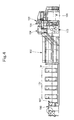
- Fig. 4 is a schematic diagram showing an example of the printing press according to the first example.
- a web W fed seamlessly from a feeding unit 100 is subjected to printing of several colors while passing through double-sided printing units 101 of four colors, namely, yellow (Y), magenta (M), cyan (C) and black (K).
- the web W is then heated and dried while passing through a drying unit 102 and thereafter cooled while passing through a cooling unit 103. Subsequently, the web W is subjected to tension control or directional change while passing through a web path unit 104 and a dragging unit 105, and finally cut in a predetermined shape and folded by a folding unit 106. Meanwhile, a web guiding unit 107 is provided upstream of the drying unit 102 (in the illustrated example, provided to the feeding unit 100), and a web guiding unit 108 is provided downstream of the drying unit 102 (in the illustrated example, provided to the dragging unit 105).
- a web guiding unit 107 is provided upstream of the drying unit 102 (in the illustrated example, provided to the feeding unit 100), and a web guiding unit 108 is provided downstream of the drying unit 102 (in the illustrated example, provided to the dragging unit 105).
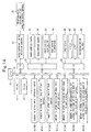
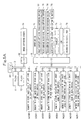
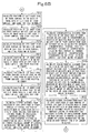
- FIGs. 1A to 1C are block diagrams showing the configuration of the register apparatus of the printing press according to the first example.
- the register apparatus of the printing press according to the first example includes, on a bus 13, a CPU 10, a ROM 11, a RAM 12 and input/output devices (hereinafter, referred to as "I/Os") 20, 30, 40 and 50.
- I/Os input/output devices
- the register apparatus of the printing press is provided with a counter 21 for detecting image-capturing timing (hereinafter, referred to as “image-capturing timing detection counter”) and a rotary encoder 22 for detecting the rotational phase in the printing press (hereinafter, referred to as “printing-press rotational-phase detection rotary encoder”).
- image-capturing timing detection counter for detecting image-capturing timing
- rotary encoder 22 for detecting the rotational phase in the printing press
- the printing-press rotational-phase detection rotary encoder 22 is attached to a rotary member of the printing press and outputs a clock pulse to the image-capturing timing detection counter 21 every time a turning movement of a given angle is made in the printing press.
- the printing-press rotational-phase detection rotary encoder 22 outputs a zero pulse once to the image-capturing timing detection counter 21 every time one complete rotation, which is based on a reference rotational phase of the printing press, is made in the printing press. Such output resets the image-capturing timing detection counter 21.
- the image-capturing timing detection counter 21 counts the clock pulse from the printing-press rotational-phase detection rotary encoder 22 that is based on the reference rotational phase of the printing press, and the count value indicates the current rotational phase of the printing press.
- Fig. 3 is a schematic diagram showing the configuration of the main part of the register apparatus of the printing press according to the first example.
- Fig. 3(a) is a schematic diagram showing the configuration of the main part of the register apparatus of the printing press according to the first example
- Fig. 3(b) is an enlarged diagram showing an example of register marks according to the first example.
- the register apparatus of the printing press includes the front-surface camera 31 and the front-surface illumination 33, which are installed above the web W, and the back-surface camera 32 and the back-surface illumination 34, which are installed below the web W.
- a register mark 1 to be used for registration is printed on each of the front and back surfaces of the web W near its left or right sheet edge.
- the register mark 1 is formed of a black register mark 2, a cyan register mark 3, a magenta register mark 4 and a yellow register mark 5. Note that Fig. 3(b) shows only the register mark 1 of each color for the front surface, but the register mark 1 of each color is also printed on the back surface of the web W at the same position.
- the front-surface camera 31 and the back-surface camera 32 each capture an image in such a way that its register mark 1 and sheet edge portion of the web W are included within an image capturing area A of a corresponding one of the front-surface camera 31 and the back-surface camera 32.
- the black register mark 2 is used as a register mark of a reference color to calculate the amounts of misregister for each color and between the front and back surfaces.
- the register apparatus of the printing press according to the first example is provided with an input device 41, a display 42, a CRT 43 and a recording device (FD, HDD) 44.
- the register apparatus of the printing press according to the first example is also provided with a first-color register adjustment mechanism 51.
- This first-color register adjustment mechanism 51 includes a front-surface first-color register adjustment device 52 and a back-surface first-color register adjustment device 53.
- the front-surface first-color register adjustment device 52 includes: a motor 55 of a front-surface first-color circumferential register adjustment unit; a motor driver 54 of the front-surface first-color circumferential register adjustment unit which controls the motor 55 of the front-surface first-color circumferential register adjustment unit; a motor 57 of a front-surface first-color lateral register adjustment unit; and a motor driver 56 of the front-surface first-color lateral register adjustment unit which controls the motor 57 of the front-surface first-color lateral register adjustment unit.
- the back-surface first-color register adjustment device 53 includes: a motor 59 of a back-surface first-color circumferential register adjustment unit; a motor driver 58 of the back-surface first-color circumferential register adjustment unit which controls the motor 59 of the back-surface first-color circumferential register adjustment unit; a motor 61 of a back-surface first-color lateral register adjustment unit; and a motor driver 60 of the back-surface first-color lateral register adjustment unit which controls the motor 61 of the back-surface first-color lateral register adjustment unit,
- the register apparatus of the printing press according to the first example further includes a second-color register adjustment mechanism 62, a third-color register adjustment mechanism 63 and a fourth-color register adjustment mechanism 64, all of which have the same configuration as that of the first-color register adjustment mechanism 51.
- a generally known structure is employed for each of the first-, second-, third- and fourth-color register adjustment mechanisms 51, 62, 63 and 64, and therefore description thereof is omitted herein (see Patent Literatures 1 and 2 listed above.)
- the register apparatus of the printing press also includes: a memory M100 to store the image capturing timing; a memory M101 to store image data of the front surface; a memory M102 to store image data of the back surface; a memory M103 to store the position of a sheet edge of the front surface; a memory M104 to store the position of the sheet edge of the back surface; a memory M105 to store the circumferential and lateral positions of the register mark of each color on the front surface; a memory M106 to store the circumferential and lateral positions of the register mark of each color on the back surface; a memory M107 to store the circumferential distance from the register mark of the reference color on the front surface to the register mark of each color on the front surface; a memory M108 to store the lateral distance from the register mark of the reference color on the front surface to the register mark of each color on the front surface; a memory M109 to store the circumferential distance from the register mark of the reference color on the back surface to the register mark of each color on the
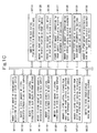
- FIGs. 2A to 2C are operation flowcharts showing the procedure of processing involving the register apparatus of the printing press and the register method for the printing press according to the first example. Meanwhile, the front-surface illumination 33 and the back-surface illumination 34 are turned on before the operation following the operation flow shown in Figs. 2A to 2C is performed, and turned off when the register apparatus ends the operation.
- Step P100 the CPU 10 compares the value of the image-capturing timing detection counter 21 with the value stored in the memory M100 to determine whether it is the timing to capture images. If determining in Step P100 that it is the timing to capture images as a result of the comparison of the value of the image-capturing timing detection counter 21 with the value stored in the memory M100, the CPU 10 executes Step P101. On the other hand, if determining in Step P100 that it is not the timing to capture images as a result of the comparison of the value of the image-capturing timing detection counter 21 with the value stored in the memory M100, the CPU 10 executes Step P100 again.
- Step P101 the CPU 10 captures an image of the front surface and stores it in the memory M101. After completing the process in Step P101, the CPU 10 executes Step P103.
- Step P103 the CPU 10 captures an image of the back surface and stores it in the memory M102. After completing the process in Step P103, the CPU 10 executes Step P105.
- Step P105 the CPU 10 calculates the circumferential and lateral positions of the register mark of each color on the front surface and store them in the memory M105. After completing the process in Step P105, the CPU 10 executes Step P106. In Step P106, the CPU 10 calculates the circumferential and lateral positions of the register mark of each color on the back surface and store them in the memory M106. After completing the process in Step P106, the CPU 10 executes Step P107.
- Steps P105 and P106 the circumferential and lateral positions of the register mark of each color on the front and back surfaces are calculated from the center position of the register mark of the corresponding color in the image data of the front and back surfaces, which is figured out through template matching.
- the template matching technique is one generally known, and thus description thereof is omitted herein (see Non-patent Literature 1 listed above).
- Step P107 the CPU 10 calculates the position of the sheet edge of the front surface and stores it in the memory M103. After completing the process in Step P107, the CPU 10 executes Step P108. In Step P108, the CPU 10 calculates the position of the sheet edge of the back surface and stores it in the memory M104. After completing the process in Step P108, the CPU 10 executes Step P109.
- the position of the sheet edge is calculated as below.
- differential values are obtained by applying a differential filter to the image data, and the largest value is determined from among the differential values thus obtained. Then, from differential values in the vicinity of the determined largest value, a formula that represents the distribution thereof is determined by use of the least square method, followed by the calculation of a peak value in the determined formula at which the differential value in the formula is zero. The lateral position of this peak value is then calculated. Next, from the lateral position of the calculated peak value of each line, a formula corresponding to the sheet edge line is determined by use of the least square method.
- the value of a circumferential position that is the same as the circumferential position of each register mark obtained in Step P105 or P106, i.e., lateral position, is set as the position of the sheet edge.
- the edge extraction method with the differential filter is one generally known, and thus description thereof is omitted here (see Non-patent Literature 1 listed above).
- Step P109 the CPU 10 calculates the circumferential distance from the register mark of the reference color on the front surface to the register mark of each color on the front surface and stores it in the memory M107. From each of the distance value so calculated, the CPU 10 subtracts a circumferential reference distance for the corresponding color on the front surface stored in the memory M111 to thereby calculate the amount of circumferential misregister for the color on the front surface, and stores the amount in the memory M115. Note that the amount of circumferential misregister can be figured out from the circumferential distance after the subtraction, the magnification of the image-capturing camera, and the pitch of the CCD elements of the image-capturing camera. After completing the process in Step P109, the CPU 10 executes Step P110.
- Step P110 the CPU 10 calculates the lateral distance from the register mark of the reference color on the front surface to the register mark of each color on the front surface and stores it in the memory M108. From each of the distance values so calculated, the CPU 10 subtracts a lateral reference distance for the corresponding color on the front surface stored in the memory M112 to thereby calculate the amounts of lateral misregister between the colors on the front surface, and stores the amounts in the memory M116. After completing the process in Step P110, the CPU 10 executes Step P111.
- Step P111 the CPU 10 calculates the circumferential distance from the register mark of the reference color on the back surface to the register mark of each color on the back surface and stores it to the memory M109. From each of the distance values so calculated, the CPU 10 subtracts a circumferential reference distance for the corresponding color on the back surface stored in the memory M113 to thereby calculate the amount of circumferential misregister for the color on the back surface, and stores the amount in the memory M118. After completing the process in Step P111, the CPU 10 executes Step P112.
- Step P112 the CPU 10 calculates the lateral distance from the register mark of the reference color on the back surface to the register mark of each color on the back surface and stores it in the memory M110. From each of the distance values so calculated, the CPU 10 subtracts a lateral reference distance for the corresponding color on the back surface stored in the memory M114 to thereby calculate the amounts of lateral misregister between the colors on the back surface, and stores the amounts in the memory M119. After completing the process in Step P112, the CPU 10 executes Step P113.
- Step P113 the CPU 10 calculates the lateral distance from the sheet edge of the front surface to the register mark of the reference color on the front surface and stores it in the memory M121. From the distance value so calculated, the CPU 10 subtracts a front-surface printing-position reference distance stored in the memory M123 to thereby calculate the amount of lateral offset of the printing position on the front surface, and stores the amount in the memory M125, After completing the process in Step P113, the CPU 10 executes Step P114.
- Step P114 the CPU 10 calculates the lateral distance from the sheet edge of the back surface to the register mark of the reference color on the back surface and stores it in the memory M122. From the distance value so calculated, the CPU 10 subtracts a back-surface printing-position reference distance stored in the memory M124 to thereby calculate the amount of lateral offset of the printing position on the back surface, and stores the amount in the memory M126. After completing the process in Step P114, the CPU 10 executes Step P115.
- Step P115 the CPU 10 adds the amount of lateral offset of the printing position on the front surface to each of the amounts of lateral misregister between the colors on the front surface to thereby calculate the amounts of lateral misregister for the colors on the front surface, and stores the amounts in the memory M117.
- each amount of lateral misregister can be figured out from the amount of lateral misregister after the addition, the magnification of the image-capturing camera, and the pitch of the CCD elements of the image-capturing camera.
- Step P116 the CPU 10 adds the amount of lateral offset of the printing position on the back surface to each of the amounts of lateral misregister between the colors on the back surface to thereby calculate the amounts of lateral misregister for the colors on the back surface, and stores the amounts in the memory M120. After completing the process in Step P116, the CPU 10 executes Step P117.
- Step P117 the CPU 10 calculates the amount of correction for the front-surface circumferential register adjustment unit of each color on the basis of the circumferential misregister for the corresponding color on the front surface, and stores the amount in the memory M127.
- the amount of correction for the circumferential register adjustment unit can be figured out from the amount of circumferential misregister figured out in Step P109 and the relationship between the amount of drive given to the motor of the circumferential register adjustment unit and the amount of circumferential movement the motor provides.
- Step P118 the CPU 10 calculates the amount of correction for the front-surface lateral register adjustment unit of each color on the basis of the lateral misregister for the corresponding color on the front surface, and stores the amount in the memory M128.
- the amount of correction for the lateral register adjustment unit can be figured out from the amount of lateral misregister figured out in Step P115 and the relationship between the amount of drive given to the motor of the lateral register adjustment unit and the amount of lateral movement the motor provides.
- Step P119 the CPU 10 calculates the amount of correction for the back-surface circumferential register adjustment unit of each color on the basis of the circumferential misregister for the corresponding color on the back surface, and stores the amount in the memory M129. After completing the process in Step P119, the CPU 10 executes Step P120.
- Step P120 the CPU 10 calculates the amount of correction for the back-surface lateral register adjustment unit of each color on the basis of the lateral misregister for the corresponding color on the back surface, and stores the amount in the memory M130. After completing the process in Step P120, the CPU 10 executes Step P121.
- Step P121 the CPU 10 outputs the amounts of correction to the motor drivers of the front-surface circumferential and lateral register adjustment units of each color. After completing the process in Step P121, the CPU 10 executes Step P122.
- Step P122 the CPU 10 outputs the amounts of correction to the motor drivers of the back-surface circumferential and lateral register adjustment units of each color.
- the motors of the front- and back-surface circumferential and lateral register adjustment units of each color are adjusted.
- the CPU 10 ends the series of processes and repeats the operation flow until receiving a command to end the control.
- the above is the procedure of the processing involving the register apparatus of the printing press and the register method for the printing press according to the first example.
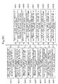
- FIG. 9 is a schematic diagram showing an example of the printing press according to the first example.
- a four-color sheet-fed double-sided rotary printing press in Fig. 9 as the printing press according to the second example is formed of a feeding section 200, a printing section 201 and a delivery section 202.
- An impression cylinder 203a which appears first in the printing section 201 is fed with paper sheets S (see Figs.
- the printing section 201 is formed of four front-surface printing units 207A to 207D and four back-surface printing units 208A to 208D.
- the front-surface printing units 207A to 207D responsible respectively for first to fourth colors are each formed by providing a blanket cylinder 204a, a plate cylinder 205a and an inker 206a sequentially on an upper portion of the impression cylinder 203a given a sheet gripper.
- the back-surface printing units 208A to 208D responsible respectively for the first to fourth colors are each formed by providing a blanket cylinder 204b, a plate cylinder 205b and an inker 206b sequentially on a lower portion of the impression cylinder 203b given a sheet gripper.
- the impression cylinders 203a of the four front-surface printing units 207A to 207D and the impression cylinders 203b of the four back-surface printing units 208A to 208D have diameters twice as large as those of their adjacent plate cylinders 205a and 205b.
- P and G in Fig. 9 denote the printing position and the gripping change position, respectively.
- the first to fourth colors in the second example correspond to four colors, namely, yellow (Y) , magenta (M), cyan (C) and black (K), respectively.
- FIGs. 5A to 5C are block diagrams showing the configuration of the register apparatus of the printing press according to the second example.
- the register apparatus of the printing press according to the second example includes, on a bus 13, a CPU 10, a ROM 11, a RAM 12 and I/Os 30, 70 and 80.
- the register apparatus of the printing press according to the second example is provided with an image-capturing camera 35.
- the register apparatus of the printing press according to the second example is also provided with an input device 71, a button 72 for capturing an image of a left side of the front surface (hereinafter, referred to as "front-surface left-side image-capturing button"), a front-surface right-side image-capturing button 73, a back-surface left-side image-capturing button 74, a back-surface right-side image-capturing button 75, a display 76, a CRT 77, a recording device (FD, HDD) 78.
- FIG. 7 is a perspective view showing the configuration of the main part of the register apparatus of the printing press according to the second example.
- Fig. 8 is a schematic diagram showing the configuration of the main part of the register apparatus of the printing press according to the second example.
- Fig. 8(a) is a schematic diagram showing the configuration of the main part of the register apparatus of the printing press according to the second example
- Fig. 8(b) is an enlarged diagram showing an example of register marks according to the second example.
- the register apparatus of the printing press includes the image-capturing camera 35 which the operator places on a paper sheet S over a color check table 36.
- the image-capturing camera 35 includes the front-surface left-side image-capturing button 72, the front-surface right-side image-capturing button 73, the back-surface left-side image-capturing button 74 and the back-surface right-side image-capturing button 75. Note that the image-capturing camera 35 includes an illumination therein so that it can capture images.
- a register mark 1 to be used for registration is printed on left and right sheet edge portions of the paper sheet S near the top side thereof.
- the register mark 1 is formed of a black register mark 2, a cyan register mark 3, a magenta register mark 4 and a yellow register mark 5 and is printed on the front and back surfaces of the paper sheet S.
- an image is so captured that the register mark 1 and a sheet edge portion of the paper sheet S are included within an image-capturing area A of the image-capturing camera 35.
- the front-surface left-side image-capturing button 72 is pushed with the register mark 1 on the left side of the front surface and a sheet edge portion of the paper sheet S being included within the image-capturing area A.
- the front-surface right-side image-capturing button 73 is pushed with the register mark 1 on the right side of the front surface and a sheet edge portion of the paper sheet S being included within the image-capturing area A.
- the back-surface left-side image-capturing button 74 is pushed with the register mark 1 on the left side of the back surface and a sheet edge portion of the paper sheet S being included within the image-capturing area A.
- the back-surface right-side image-capturing button 75 is pushed with the register mark 1 on the right side of the back surface and a sheet edge portion of the paper sheet S being included within the image-capturing area A.
- the image-capturing camera 35 includes the front-surface left-side image-capturing button 72, the front-surface right-side image-capturing button 73, the back-surface left-side image-capturing button 74 and the back-surface right-side image-capturing button 75. Note, however, that it is possible to employ a configuration where the image-capturing camera 35 captures an image of each register mark 1 with a single image-capturing button by previously determining the order of capturing images for the register marks 1 on the left side of the front surface, the right side of the front surface, the left side of the back surface, and the right side of the back surface.
- the register apparatus of the printing press according to the second example is provided with a first-color register adjustment mechanism 81.
- This first-color register adjustment mechanism 81 includes a front-surface first-color register adjustment mechanism 82 and a back-surface first-color register adjustment mechanism 83.
- the front-surface first-color register adjustment device 82 includes: a motor 85 of a front-surface first-color circumferential register adjustment unit; a motor driver 84 of the front-surface first-color circumferential register adjustment unit which controls the motor 85 of the front-surface first-color circumferential register adjustment unit; a motor 87 of a front-surface first-color lateral register adjustment unit; a motor driver 86 of the front-surface first-color lateral register adjustment unit which controls the motor 87 of the front-surface first-color lateral register adjustment unit; a motor 89 of a front-surface first-color skewing register adjustment unit; and a motor driver 88 of the front-surface first-color skewing register adjustment unit which controls the motor 89 of the front-surface first-color skewing register adjustment unit.
- the back-surface first-color register adjustment device 83 includes: a motor 91 of a back-surface first-color circumferential register adjustment unit; a motor driver 90 of the back-surface first-color circumferential register adjustment unit which controls the motor 91 of the back-surface first-color circumferential register adjustment unit; a motor 93 of a back-surface first-color lateral register adjustment unit; a motor driver 92 of the back-surface first-color lateral register adjustment unit which controls the motor 93 of the back-surface first-color lateral register adjustment unit; a motor 95 of a back-surface first-color skewing register adjustment unit; and a motor driver 88 of the back-surface first-color skewing register adjustment unit which controls the motor 94 of the back-surface first-color skewing register adjustment unit.
- the register apparatus of the printing press according to the first example further includes a second-color register adjustment mechanism 96, a third-color register adjustment mechanism 97 and a fourth-color register adjustment mechanism 98, all of which have the same configuration as that of the first-color register adjustment mechanism 81.
- a generally known structure is employed for each of the first-, second-, third- and fourth-color register adjustment mechanisms 81, 96, 97 and 98, and therefore description thereof is omitted herein (see Patent Literatures 1 and 2 listed above.)
- the register apparatus of the printing press includes: a memory M200 to store image data of the left side of the front surface; a memory M201 to store image data of the right side of the front surface; a memory M202 to store image data of the left side of the back surface; a memory M203 to store image data of the right side of the back surface; a memory M204 to store the position of a left sheet edge of the front surface; a memory M205 to store the position of a top sheet edge of the front surface on the left side; a memory M206 to store the position of a left sheet edge of the back surface; a memory M207 to store the position of a top sheet edge of the back surface on the left side; a memory M208 to store the position of a top sheet edge of the front surface on the right side; a memory M209 to store the position of a top sheet edge of the back surface on the right side; a memory M210 to store the circumferential and lateral positions of the register mark of each color on the left side of the
- FIGs. 6A to 6C are operation flowcharts showing the procedure of processing involving the register apparatus of the printing press and the register method for the printing press according to the second example.
- Step P200 moves the image-capturing camera 35 to a position above the register mark on the left side of the front surface and pushes the front-surface left-side image-capturing button 72.
- Step P201 the CPU 10 captures an image of the left side of the front surface by use of the image-capturing camera 35 and stores it in the memory M200.
- the CPU 10 executes Step P202.
- Step P202 the operator moves the image-capturing camera 35 to a position above the register mark on the right side of the front surface and pushes the front-surface right-side image-capturing button 73.
- Step P203 the CPU 10 captures an image of the right side of the front surface by use of the image-capturing camera 35 and stores it in the memory M201. After completing the process in Step P203, the CPU 10 executes Step P204.
- Step P204 after the operator flips and places the paper sheet S on the color check table 36 with the back surface up, the operator moves the image-capturing camera 35 to a position above the register mark on the left side of the back surface and pushes the back-surface left-side image-capturing button 74.
- Step P205 the CPU 10 captures an image of the left side of the back surface and stores it in the memory M202. After completing the process in Step P205, the CPU 10 executes Step P206.
- Step P206 the operator moves the image-capturing camera 35 to a position above the register mark on the right side of the back surface and pushes the back-surface right-side image-capturing button 73.
- Step P207 the CPU 10 captures an image of the right side of the back surface by use of the image-capturing camera 35 and stores it in the memory M203. After completing the process in Step P207, the CPU 10 executes Step P208.
- Step P208 based on the image data of the left side of the front surface, the CPU 10 calculates the circumferential and lateral positions of the corresponding register mark of each color and stores them in the memory M210. After completing the process in Step P208, the CPU 10 executes Step P209.
- Step P209 based on the image data of the left side of the back surface, the CPU 10 calculates the circumferential and lateral positions of the corresponding register mark of each color and stores them in the memory M211. After completing the process in Step P209, the CPU 10 executes Step P210.
- Step P210 based on the image data of the right side of the front surface, the CPU 10 calculates the circumferential and lateral positions of the corresponding register mark of each color and stores them in the memory M212. After completing the process in Step P210, the CPU 10 executes Step P211.
- Step P211 based on the image data of the right side of the back surface, the CPU 10 calculates the circumferential and lateral positions of the corresponding register mark of each color and stores them in the memory M213. After completing the process in Step P211, the CPU 10 executes Step P212.
- Steps P208 to P211 the circumferential and lateral positions of the register mark of each color on the front and back surfaces are calculated from the center position of the register mark of the corresponding color in the image data of the front and back surfaces, which is figured out through template matching.
- the template matching technique is one generally known, and thus description thereof is omitted herein (see Non-patent Literature 1 listed above).
- Step P212 the CPU 10 calculates the position of the left sheet edge of the front surface on the basis of the image data of the left side of the front surface, and stores the position in the memory M204. After completing the process in Step P212, the CPU 10 executes Step P213.
- Step P213 the CPU 10 calculates the position of the top sheet edge of the left side of the front surface on the basis of the image data of the left side of the front surface, and stores the position in the memory M205. After completing the process in Step P213, the CPU 10 executes Step P214.
- Step P214 the CPU 10 calculates the position of the left sheet edge of the back surface on the basis of the image data of the left side of the back surface, and stores the position in the memory M206. After completing the process in Step P214, the CPU 10 executes Step P215.
- Step P215 the CPU 10 calculates the position of the top sheet edge of the left side of the back surface on the basis of the image data of the left side of the back surface, and stores the position in the memory M207. After completing the process in Step P215, the CPU 10 executes Step P216.
- Step P216 the CPU 10 calculates the position of the top sheet edge of the right side of the front surface on the basis of the image data of the right side of the front surface, and stores the position in the memory M208. After completing the process in Step P216, the CPU 10 executes Step P217.
- Step P217 the CPU 10 calculates the position of the top sheet edge of the right side of the back surface on the basis of the image data of the right side of the back surface, and stores the position in the memory M209. After completing the process in Step P217, the CPU 10 executes Step P218.
- Steps P212 and P214 the position of the left sheet edge is calculated as below.
- differential values are obtained by applying a differential filter to the image data, and the largest value is determined from among the differential values thus obtained. Then, from differential values in the vicinity of the determined largest value, a formula that represents the distribution thereof is determined by use of the least square method, followed by the calculation of a peak value in the determined formula at which the differential value in the formula is zero. The lateral position of this peak value is then calculated.
- a formula corresponding to the sheet edge line is determined by use of the least square method.
- the value of a circumferential position that is the same as the circumferential position of each register mark obtained in Step P208, P209, P210 or P211, i.e., lateral position is set as the position of the sheet edge.
- the position of the top sheet edge is calculated as below.
- Step P218 the CPU 10 calculates the lateral distance from the position of the left sheet edge of the front surface to the lateral position of the register mark of each color on the left side of the front surface, and stores the distance in the memory M214. From each of the distance values so calculated, the CPU 10 subtracts a lateral printing position reference distance for the corresponding color on the front surface stored in the memory M220 to thereby calculate the amount of lateral misregister for the color on the front surface, and stores the amount in the memory M224. Note that the amount of lateral misregister can be figured out from the lateral distance after the subtraction, the magnification of the image-capturing camera, and the pitch of the CCD elements of the image-capturing camera. After completing the process in Step P218, the CPU 10 executes Step P219.
- Step P219 the CPU 10 calculates the circumferential distance from the position of the top sheet edge of the front surface on the left side to the circumferential position of the register mark of each color on the left side of the front surface, and stores the distance in the memory M215. From each of the distance values so calculated, the CPU 10 subtracts a circumferential printing position reference distance for the corresponding color on the front surface stored in the memory M221 to thereby calculate the amount of circumferential misregister for the color on the front surface, and stores the amount in the memory M225. Note that the amount of circumferential misregister can be figured out from the circumferential distance after the subtraction, the magnification of the image-capturing camera, and the pitch of the CCD elements of the image-capturing camera. After completing the process in Step P219, the CPU 10 executes Step P220.
- Step P220 the CPU 10 calculates the circumferential distance from the position of the top sheet edge of the front surface on the right side to the circumferential position of the register mark of each color on the right side of the front surface, and stores the distance in the memory M216. From each of the distance values so calculated, the CPU 10 subtracts a circumferential printing position reference distance for the corresponding color on the front surface stored in the memory M215 to thereby calculate the amount of skewing misregister for the color on the front surface, and stores the amount in the memory M226. Note that the amount of skewing misregister can be figured out from the circumferential distance after the subtraction, the magnification of the image-capturing camera, and the pitch of the CCD elements of the image-capturing camera. After completing the process in Step P220, the CPU 10 executes Step P221.
- Step P221 the CPU 10 calculates the lateral distance from the position of the left sheet edge of the back surface to the lateral position of the register mark of each color on the left side of the back surface, and stores the distance in the memory M217. From each of the distance values so calculated, the CPU 10 subtracts a circumferential printing position reference distance for the corresponding color on the back surface stored in the memory M222 to thereby calculate the amount of lateral misregister for the color on the back surface, and stores the amount in the memory M227. After completing the process in Step P221, the CPU 10 executes Step P222.
- Step P222 the CPU 10 calculates the circumferential distance from the position of the top sheet edge of the back surface on the left side to the circumferential position of the register mark of each color on the left side of the back surface, and stores the distance in the memory M218. From each of the distance values so calculated, the CPU 10 subtracts a circumferential printing position reference distance for the corresponding color on the back surface stored in the memory M223 to thereby calculate the amount of circumferential misregister for the color on the back surface, and stores the amount in the memory M228. After completing the process in Step P222, the CPU 10 executes Step P223.
- Step P223 the CPU 10 calculates the circumferential distance from the position of the top sheet edge of the back surface on the right side to the circumferential position of the register mark of each color on the right side of the back surface, and stores the distance in the memory M219. From each of the distance values so calculated, the CPU 10 subtracts a circumferential printing position reference distance for the corresponding color on the back surface stored in the memory M218 to thereby calculate the amount of skewing misregister for the color on the back surface, and stores the amount in the memory M229. After completing the process in Step P223, the CPU 10 executes Step P224.
- Step P224 the CPU 10 calculates the amount of correction for the front-surface circumferential register adjustment unit of each color on the basis of the circumferential misregister for the corresponding color on the front surface, and stores the amount in the memory M230.
- the amount of correction for the circumferential register adjustment unit can be figured out from the circumferential misregister figured out in Step P219 and the relationship between the amount of drive given to the motor of the circumferential register adjustment unit and the amount of circumferential movement the motor provides.
- Step P225 the CPU 10 calculates the amount of correction for the front-surface lateral register adjustment unit of each color on the basis of the lateral misregister for the corresponding color on the front surface, and stores the amount in the memory M231. Note that the amount of correction for the lateral register adjustment unit can be figured out from the lateral misregister figured out in Step P218 and the relationship between the amount of drive given to the motor of the lateral register adjustment unit and the amount of lateral movement the motor provides. After completing the process in Step P225, the CPU 10 executes Step P226.
- Step P226 the CPU 10 calculates the amount of correction for the front-surface skewing register adjustment unit of each color on the basis of the skewing misregister for the corresponding color on the front surface, and stores the amount in the memory M232.
- the amount of correction for the skewing misregister adjustment device can be figured out from the amount of skewing misregister figured out in Step P220, and the distances from the register mark of the corresponding color on the left side and that on the right side to an adjustment reference point of a mechanism of the skewing register adjustment unit, as well as the relationship between the amount of drive given to the motor of skewing register adjustment unit and the degree of skewing angle the motor changes.
- Step P227 the CPU 10 executes Step P227.
- Step P227 the CPU 10 calculates the amount of correction for the back-surface circumferential register adjustment unit of each color on the basis of the circumferential misregister for the corresponding color on the back surface, and stores the amount in the memory M233. After completing the process in Step P227, the CPU 10 executes Step P228.
- Step P228 the CPU 10 calculates the amount of correction for the back-surface lateral register adjustment unit of each color on the basis of the lateral misregister for the corresponding color on the back surface, and stores the amount in the memory M234. After completing the process in Step P228, the CPU 10 executes Step P229.
- Step P229 the CPU 10 calculates the amount of correction for the back-surface skewing register adjustment unit of each color on the basis of the skewing misregister for the corresponding color on the back surface, and stores the amount in the memory M235. After completing the process in Step P229, the CPU 10 executes Step P230.
- Step P230 the CPU 10 outputs the amounts of correction to the motor drivers of the circumferential, lateral and skewing register adjustment units of each color on the front surface. After completing the process in Step P230, the CPU 10 executes Step P231.
- Step P231 the CPU 10 outputs the amounts of correction to the motor drivers of the circumferential, lateral and skewing register adjustment units of each color on the back surface.
- the motors of the front- and back-surface circumferential, lateral and skewing register adjustment units of each color are adjusted.
- the CPU 10 ends the series of processes and repeats the operation flow until receiving a command to end the control.
- the above is the procedure of the processing involving the register apparatus of the printing press and the register method for the printing press according to the second example.
- each of the front- and back-surface cameras 31 and 32 or the image-capturing camera 35 captures the register mark 1 and its corresponding edge of the print sheet collectively in one image, and the amount of misregister for each color and between the front and back surfaces is calculated on the basis of the position of the register mark 1 relative to that of the edge of the print sheet.
- the present invention can be used for the registration for each color and between the front and back surfaces in printing presses.
Landscapes
- Engineering & Computer Science (AREA)
- Mechanical Engineering (AREA)
- Inking, Control Or Cleaning Of Printing Machines (AREA)
- Rotary Presses (AREA)
Applications Claiming Priority (1)
| Application Number | Priority Date | Filing Date | Title |
|---|---|---|---|
| JP2009271293A JP2011110885A (ja) | 2009-11-30 | 2009-11-30 | 印刷機の見当合わせ装置及び印刷機の見当合わせ方法 |
Publications (1)
| Publication Number | Publication Date |
|---|---|
| EP2327548A1 true EP2327548A1 (en) | 2011-06-01 |
Family
ID=43606812
Family Applications (1)
| Application Number | Title | Priority Date | Filing Date |
|---|---|---|---|
| EP10192642A Withdrawn EP2327548A1 (en) | 2009-11-30 | 2010-11-25 | Register apparatus of printing press and register method for printing press |
Country Status (4)
| Country | Link |
|---|---|
| US (1) | US20110126729A1 (enExample) |
| EP (1) | EP2327548A1 (enExample) |
| JP (1) | JP2011110885A (enExample) |
| CN (1) | CN102079160A (enExample) |
Cited By (4)
| Publication number | Priority date | Publication date | Assignee | Title |
|---|---|---|---|---|
| WO2014029418A1 (en) * | 2012-08-20 | 2014-02-27 | Hewlett-Packard Indigo Bv | Color registration calibration method for a printer apparatus |
| US9393772B2 (en) | 2012-05-02 | 2016-07-19 | Advanced Vision Technology (Avt) Ltd. | Method and system for registering printing stations of a printing press |
| US10315412B2 (en) | 2012-05-02 | 2019-06-11 | Advanced Vision Technology (Avt) Ltd. | Method and system for registering printing stations of a printing press |
| US10657640B2 (en) | 2017-08-21 | 2020-05-19 | Advanced Vision Technology (A.V.T.) Ltd. | System and method for generating images for inspection |
Families Citing this family (15)
| Publication number | Priority date | Publication date | Assignee | Title |
|---|---|---|---|---|
| US8594555B2 (en) * | 2011-04-27 | 2013-11-26 | Xerox Corporation | Media registration in a duplex printing system |
| JP5636349B2 (ja) * | 2011-09-09 | 2014-12-03 | 株式会社ミヤコシ | 枚葉デジタル印刷方法 |
| CN102371750B (zh) * | 2011-11-27 | 2016-08-03 | 西安新达机械有限公司 | 一种高速药用铝箔印刷涂布机正反印套准方法 |
| JP2014206437A (ja) * | 2013-04-12 | 2014-10-30 | 住友重機械工業株式会社 | グラビア印刷機用マークセンサ |
| JP6030732B1 (ja) * | 2015-09-09 | 2016-11-24 | 株式会社小森コーポレーション | 見当誤差量検出方法および装置 |
| JP6523903B2 (ja) * | 2015-09-28 | 2019-06-05 | 株式会社Screenホールディングス | 印刷装置および印刷方法 |
| US10232247B2 (en) | 2015-10-19 | 2019-03-19 | Hydra Management Llc | Instant ticket redundancy via multi-chromatic indicia |
| US10252555B2 (en) | 2015-10-19 | 2019-04-09 | Hydra Management Llc | Instant ticket redundancy via multi-chromatic indicia |
| US10377162B2 (en) | 2015-10-19 | 2019-08-13 | Hydra Management Llc | Instant ticket redundancy via multi-chromatic indicia |
| CN105291561B (zh) * | 2015-11-18 | 2018-08-07 | 宁波欣达印刷机器有限公司 | 套印精度检测系统及套印精度检测方法 |
| JP6547647B2 (ja) * | 2016-02-02 | 2019-07-24 | コニカミノルタ株式会社 | 画像読取装置、画像形成システム、及びプログラム |
| CN109891330A (zh) * | 2016-07-12 | 2019-06-14 | 海德拉管理有限责任公司 | 具有多个排列式成像器的闭环色彩校准 |
| CN110509680B (zh) * | 2019-09-10 | 2020-12-29 | 深圳市冠为科技股份有限公司 | 一种印刷套准方法及系统 |
| CN113665252B (zh) * | 2020-05-14 | 2023-03-07 | 卡西欧计算机株式会社 | 印刷装置、印刷装置的控制方法以及记录介质 |
| CN114654882B (zh) * | 2022-03-30 | 2024-02-13 | 上海紫泉标签有限公司 | 一种黑白膜印刷的横向套准方法 |
Citations (4)
| Publication number | Priority date | Publication date | Assignee | Title |
|---|---|---|---|---|
| JPS61118249A (ja) | 1984-11-15 | 1986-06-05 | Dainippon Printing Co Ltd | 印刷機の見当合せ装置 |
| JPS6442135A (en) | 1987-08-07 | 1989-02-14 | Mitsubishi Electric Corp | Semiconductor device |
| WO2000027638A1 (en) * | 1998-10-23 | 2000-05-18 | Cc1, Inc. | System and method for register mark recognition |
| US20020024681A1 (en) * | 2000-06-28 | 2002-02-28 | Holger Leonhardt | Method for determining a printing-image position, and monitoring device for a printing machine |
Family Cites Families (15)
| Publication number | Priority date | Publication date | Assignee | Title |
|---|---|---|---|---|
| US4546700A (en) * | 1981-12-30 | 1985-10-15 | Kollmorgen Technologies Corporation | Method and apparatus for sensing and maintaining color registration |
| JPS58185257A (ja) * | 1982-04-26 | 1983-10-28 | Dainippon Printing Co Ltd | オフセツト印刷機の見当合せ方法 |
| JP2812988B2 (ja) * | 1989-05-30 | 1998-10-22 | 株式会社小森コーポレーション | 印刷機における見当量検出方法及びその装置 |
| US6199480B1 (en) * | 1992-06-06 | 2001-03-13 | Heideiberger Druckmaschinen | Arrangement for determining register deviations of a multicolor rotary printing machine |
| US6129015A (en) * | 1993-11-23 | 2000-10-10 | Quad/Tech, Inc. | Method and apparatus for registering color in a printing press |
| CH690470A5 (fr) * | 1994-06-17 | 2000-09-15 | Bobst Sa | Dispositif pour assurer la qualité de la production d'une presse de fabrication d'emballages. |
| US6874420B2 (en) * | 1999-10-22 | 2005-04-05 | Cc1, Inc. | System and method for register mark recognition |
| JP2004279749A (ja) * | 2003-03-17 | 2004-10-07 | Fuji Xerox Co Ltd | 画像形成装置 |
| JP2006130795A (ja) * | 2004-11-05 | 2006-05-25 | Toyo Inspections Kk | 印刷紙面複合検査装置 |
| US7665400B2 (en) * | 2004-11-08 | 2010-02-23 | Scientific Games International, Inc. | Print monitoring system and method |
| US7343858B2 (en) * | 2005-04-20 | 2008-03-18 | Preco Industries, Inc | Method for tracking a registered pattern to a continuous web |
| EP1803565A1 (de) * | 2005-12-27 | 2007-07-04 | Fischer & Krecke GmbH & Co. KG | Verfahren zum Druckwerkwechsel an einer laufenden Rotations-Druckmaschine |
| JP4743773B2 (ja) * | 2006-06-01 | 2011-08-10 | コニカミノルタセンシング株式会社 | エッジ検出方法、装置、及びプログラム |
| KR101279032B1 (ko) * | 2006-12-15 | 2013-07-02 | 삼성전자주식회사 | 화상 형성 장치 및 그 자동 컬러 정렬 방법 |
| JP2008260193A (ja) * | 2007-04-11 | 2008-10-30 | Komori Corp | 印刷物の色間見当誤差量検出方法および装置 |
-
2009
- 2009-11-30 JP JP2009271293A patent/JP2011110885A/ja active Pending
-
2010
- 2010-11-25 EP EP10192642A patent/EP2327548A1/en not_active Withdrawn
- 2010-11-29 US US12/955,589 patent/US20110126729A1/en not_active Abandoned
- 2010-11-30 CN CN2010105711919A patent/CN102079160A/zh active Pending
Patent Citations (4)
| Publication number | Priority date | Publication date | Assignee | Title |
|---|---|---|---|---|
| JPS61118249A (ja) | 1984-11-15 | 1986-06-05 | Dainippon Printing Co Ltd | 印刷機の見当合せ装置 |
| JPS6442135A (en) | 1987-08-07 | 1989-02-14 | Mitsubishi Electric Corp | Semiconductor device |
| WO2000027638A1 (en) * | 1998-10-23 | 2000-05-18 | Cc1, Inc. | System and method for register mark recognition |
| US20020024681A1 (en) * | 2000-06-28 | 2002-02-28 | Holger Leonhardt | Method for determining a printing-image position, and monitoring device for a printing machine |
Non-Patent Citations (1)
| Title |
|---|
| MASATOSHI OKUTOMI: "Digital Image Processing", 1 March 2006, COMPUTER GRAPHIC ARTS SOCIETY, pages: 114 - 121 202, |
Cited By (4)
| Publication number | Priority date | Publication date | Assignee | Title |
|---|---|---|---|---|
| US9393772B2 (en) | 2012-05-02 | 2016-07-19 | Advanced Vision Technology (Avt) Ltd. | Method and system for registering printing stations of a printing press |
| US10315412B2 (en) | 2012-05-02 | 2019-06-11 | Advanced Vision Technology (Avt) Ltd. | Method and system for registering printing stations of a printing press |
| WO2014029418A1 (en) * | 2012-08-20 | 2014-02-27 | Hewlett-Packard Indigo Bv | Color registration calibration method for a printer apparatus |
| US10657640B2 (en) | 2017-08-21 | 2020-05-19 | Advanced Vision Technology (A.V.T.) Ltd. | System and method for generating images for inspection |
Also Published As
| Publication number | Publication date |
|---|---|
| JP2011110885A (ja) | 2011-06-09 |
| US20110126729A1 (en) | 2011-06-02 |
| CN102079160A (zh) | 2011-06-01 |
Similar Documents
| Publication | Publication Date | Title |
|---|---|---|
| EP2327548A1 (en) | Register apparatus of printing press and register method for printing press | |
| US10867222B2 (en) | Printed object management apparatus and management method | |
| US6796240B2 (en) | Printing press register control using colorpatch targets | |
| JP2016013681A (ja) | 印刷機および印刷方法 | |
| CN101336168A (zh) | 用于印刷质量测量的设备,系统和方法 | |
| US20200005104A1 (en) | Control device and inspection device | |
| EP3486086A1 (en) | Print quality examination device | |
| EP2384889A1 (en) | Method for adjusting and controlling a printing machine by employing minute marks | |
| JP2003341017A (ja) | 印刷機における見当合せ方法及び印刷機 | |
| US20100208280A1 (en) | Method for Printing A Substrate | |
| JP2006256216A (ja) | 多色刷り印刷装置、多色刷り印刷方法ならびに印刷見当マーク | |
| JP7649221B2 (ja) | 印刷機 | |
| FI3280594T3 (fi) | Rekisteröintijärjestelmä käsin säädettävällä painorekisterillä varustetun pyörivän painokoneen painatusyksikköjä varten | |
| JP2006346955A (ja) | 印刷管理スケール、印刷システムおよび印刷方法 | |
| CN104441970A (zh) | 一种喷墨印刷中重影的修正方法及装置 | |
| US20140196621A1 (en) | Rotary offset printing machine and method for printing on substrates | |
| JP2006346955A5 (enExample) | ||
| JP2011110890A (ja) | 印刷機の見当合わせ装置及び印刷機の見当合わせ方法 | |
| JP2005131795A (ja) | 見当マーク群および見当微調整装置 | |
| JP2011110889A (ja) | 印刷機の見当合わせ装置及び印刷機の見当合わせ方法 | |
| JP6821169B2 (ja) | 刷版加工方法及び刷版加工装置 | |
| JP7813975B1 (ja) | 見当制御装置 | |
| JP2016055581A (ja) | 印刷機の見当ずれ検出用撮像手段の位置調整方法及び装置 | |
| DE102015200148B4 (de) | Verfahren zur Anpassung mindestens einer Länge einer auf mehreren Druckbogen jeweils gleich groß drucktechnisch auszubildenden Fläche | |
| JP2006256205A (ja) | 多色刷り印刷装置、多色刷り印刷方法ならびに印刷見当マーク |
Legal Events
| Date | Code | Title | Description |
|---|---|---|---|
| PUAI | Public reference made under article 153(3) epc to a published international application that has entered the european phase |
Free format text: ORIGINAL CODE: 0009012 |
|
| AK | Designated contracting states |
Kind code of ref document: A1 Designated state(s): AL AT BE BG CH CY CZ DE DK EE ES FI FR GB GR HR HU IE IS IT LI LT LU LV MC MK MT NL NO PL PT RO RS SE SI SK SM TR |
|
| AX | Request for extension of the european patent |
Extension state: BA ME |
|
| RIN1 | Information on inventor provided before grant (corrected) |
Inventor name: KIKUCHI, MEGUMI Inventor name: IINO, TADAHIKO Inventor name: MORONO, TOMOYUKI |
|
| 17P | Request for examination filed |
Effective date: 20111007 |
|
| 17Q | First examination report despatched |
Effective date: 20120308 |
|
| STAA | Information on the status of an ep patent application or granted ep patent |
Free format text: STATUS: THE APPLICATION IS DEEMED TO BE WITHDRAWN |
|
| 18D | Application deemed to be withdrawn |
Effective date: 20120719 |