EP2301133B1 - Wireless high power transfer under regulatory constraints - Google Patents
Wireless high power transfer under regulatory constraints Download PDFInfo
- Publication number
- EP2301133B1 EP2301133B1 EP09790164.9A EP09790164A EP2301133B1 EP 2301133 B1 EP2301133 B1 EP 2301133B1 EP 09790164 A EP09790164 A EP 09790164A EP 2301133 B1 EP2301133 B1 EP 2301133B1
- Authority
- EP
- European Patent Office
- Prior art keywords
- antenna
- receiving antenna
- coil
- primary
- frequency
- Prior art date
- Legal status (The legal status is an assumption and is not a legal conclusion. Google has not performed a legal analysis and makes no representation as to the accuracy of the status listed.)
- Active
Links
- 238000012546 transfer Methods 0.000 title description 16
- 230000001105 regulatory effect Effects 0.000 title 1
- 230000008878 coupling Effects 0.000 claims description 25
- 238000010168 coupling process Methods 0.000 claims description 25
- 238000005859 coupling reaction Methods 0.000 claims description 25
- 239000003990 capacitor Substances 0.000 claims description 12
- 238000001514 detection method Methods 0.000 claims description 6
- 230000001939 inductive effect Effects 0.000 claims description 6
- 238000000034 method Methods 0.000 claims description 4
- 230000001419 dependent effect Effects 0.000 claims description 2
- 238000010586 diagram Methods 0.000 description 5
- 241000709691 Enterovirus E Species 0.000 description 4
- 229910000859 α-Fe Inorganic materials 0.000 description 4
- 230000005540 biological transmission Effects 0.000 description 3
- 238000005516 engineering process Methods 0.000 description 3
- 230000006870 function Effects 0.000 description 3
- 230000003287 optical effect Effects 0.000 description 3
- 238000012360 testing method Methods 0.000 description 3
- 238000013459 approach Methods 0.000 description 2
- 238000004891 communication Methods 0.000 description 2
- 230000007423 decrease Effects 0.000 description 2
- 230000005672 electromagnetic field Effects 0.000 description 2
- 239000000835 fiber Substances 0.000 description 2
- 239000002245 particle Substances 0.000 description 2
- 230000001902 propagating effect Effects 0.000 description 2
- 230000001681 protective effect Effects 0.000 description 2
- 230000005855 radiation Effects 0.000 description 2
- 206010016275 Fear Diseases 0.000 description 1
- 230000003321 amplification Effects 0.000 description 1
- 239000000969 carrier Substances 0.000 description 1
- 238000004590 computer program Methods 0.000 description 1
- 239000004020 conductor Substances 0.000 description 1
- 238000013461 design Methods 0.000 description 1
- 239000000428 dust Substances 0.000 description 1
- 230000000694 effects Effects 0.000 description 1
- 230000005684 electric field Effects 0.000 description 1
- 230000017525 heat dissipation Effects 0.000 description 1
- 238000010438 heat treatment Methods 0.000 description 1
- 238000013101 initial test Methods 0.000 description 1
- 230000010354 integration Effects 0.000 description 1
- 230000007246 mechanism Effects 0.000 description 1
- 238000012986 modification Methods 0.000 description 1
- 230000004048 modification Effects 0.000 description 1
- 230000005404 monopole Effects 0.000 description 1
- 238000003199 nucleic acid amplification method Methods 0.000 description 1
- 230000004044 response Effects 0.000 description 1
- 239000002689 soil Substances 0.000 description 1
Images


Classifications
-
- H—ELECTRICITY
- H02—GENERATION; CONVERSION OR DISTRIBUTION OF ELECTRIC POWER
- H02J—CIRCUIT ARRANGEMENTS OR SYSTEMS FOR SUPPLYING OR DISTRIBUTING ELECTRIC POWER; SYSTEMS FOR STORING ELECTRIC ENERGY
- H02J50/00—Circuit arrangements or systems for wireless supply or distribution of electric power
- H02J50/90—Circuit arrangements or systems for wireless supply or distribution of electric power involving detection or optimisation of position, e.g. alignment
-
- B—PERFORMING OPERATIONS; TRANSPORTING
- B60—VEHICLES IN GENERAL
- B60L—PROPULSION OF ELECTRICALLY-PROPELLED VEHICLES; SUPPLYING ELECTRIC POWER FOR AUXILIARY EQUIPMENT OF ELECTRICALLY-PROPELLED VEHICLES; ELECTRODYNAMIC BRAKE SYSTEMS FOR VEHICLES IN GENERAL; MAGNETIC SUSPENSION OR LEVITATION FOR VEHICLES; MONITORING OPERATING VARIABLES OF ELECTRICALLY-PROPELLED VEHICLES; ELECTRIC SAFETY DEVICES FOR ELECTRICALLY-PROPELLED VEHICLES
- B60L53/00—Methods of charging batteries, specially adapted for electric vehicles; Charging stations or on-board charging equipment therefor; Exchange of energy storage elements in electric vehicles
- B60L53/30—Constructional details of charging stations
- B60L53/35—Means for automatic or assisted adjustment of the relative position of charging devices and vehicles
- B60L53/38—Means for automatic or assisted adjustment of the relative position of charging devices and vehicles specially adapted for charging by inductive energy transfer
-
- B—PERFORMING OPERATIONS; TRANSPORTING
- B60—VEHICLES IN GENERAL
- B60L—PROPULSION OF ELECTRICALLY-PROPELLED VEHICLES; SUPPLYING ELECTRIC POWER FOR AUXILIARY EQUIPMENT OF ELECTRICALLY-PROPELLED VEHICLES; ELECTRODYNAMIC BRAKE SYSTEMS FOR VEHICLES IN GENERAL; MAGNETIC SUSPENSION OR LEVITATION FOR VEHICLES; MONITORING OPERATING VARIABLES OF ELECTRICALLY-PROPELLED VEHICLES; ELECTRIC SAFETY DEVICES FOR ELECTRICALLY-PROPELLED VEHICLES
- B60L53/00—Methods of charging batteries, specially adapted for electric vehicles; Charging stations or on-board charging equipment therefor; Exchange of energy storage elements in electric vehicles
- B60L53/10—Methods of charging batteries, specially adapted for electric vehicles; Charging stations or on-board charging equipment therefor; Exchange of energy storage elements in electric vehicles characterised by the energy transfer between the charging station and the vehicle
- B60L53/12—Inductive energy transfer
- B60L53/126—Methods for pairing a vehicle and a charging station, e.g. establishing a one-to-one relation between a wireless power transmitter and a wireless power receiver
-
- B—PERFORMING OPERATIONS; TRANSPORTING
- B60—VEHICLES IN GENERAL
- B60L—PROPULSION OF ELECTRICALLY-PROPELLED VEHICLES; SUPPLYING ELECTRIC POWER FOR AUXILIARY EQUIPMENT OF ELECTRICALLY-PROPELLED VEHICLES; ELECTRODYNAMIC BRAKE SYSTEMS FOR VEHICLES IN GENERAL; MAGNETIC SUSPENSION OR LEVITATION FOR VEHICLES; MONITORING OPERATING VARIABLES OF ELECTRICALLY-PROPELLED VEHICLES; ELECTRIC SAFETY DEVICES FOR ELECTRICALLY-PROPELLED VEHICLES
- B60L53/00—Methods of charging batteries, specially adapted for electric vehicles; Charging stations or on-board charging equipment therefor; Exchange of energy storage elements in electric vehicles
- B60L53/60—Monitoring or controlling charging stations
-
- H—ELECTRICITY
- H01—ELECTRIC ELEMENTS
- H01F—MAGNETS; INDUCTANCES; TRANSFORMERS; SELECTION OF MATERIALS FOR THEIR MAGNETIC PROPERTIES
- H01F38/00—Adaptations of transformers or inductances for specific applications or functions
- H01F38/14—Inductive couplings
-
- H—ELECTRICITY
- H01—ELECTRIC ELEMENTS
- H01Q—ANTENNAS, i.e. RADIO AERIALS
- H01Q1/00—Details of, or arrangements associated with, antennas
- H01Q1/12—Supports; Mounting means
- H01Q1/22—Supports; Mounting means by structural association with other equipment or articles
- H01Q1/2208—Supports; Mounting means by structural association with other equipment or articles associated with components used in interrogation type services, i.e. in systems for information exchange between an interrogator/reader and a tag/transponder, e.g. in Radio Frequency Identification [RFID] systems
- H01Q1/2225—Supports; Mounting means by structural association with other equipment or articles associated with components used in interrogation type services, i.e. in systems for information exchange between an interrogator/reader and a tag/transponder, e.g. in Radio Frequency Identification [RFID] systems used in active tags, i.e. provided with its own power source or in passive tags, i.e. deriving power from RF signal
-
- H—ELECTRICITY
- H01—ELECTRIC ELEMENTS
- H01Q—ANTENNAS, i.e. RADIO AERIALS
- H01Q7/00—Loop antennas with a substantially uniform current distribution around the loop and having a directional radiation pattern in a plane perpendicular to the plane of the loop
-
- H—ELECTRICITY
- H02—GENERATION; CONVERSION OR DISTRIBUTION OF ELECTRIC POWER
- H02J—CIRCUIT ARRANGEMENTS OR SYSTEMS FOR SUPPLYING OR DISTRIBUTING ELECTRIC POWER; SYSTEMS FOR STORING ELECTRIC ENERGY
- H02J50/00—Circuit arrangements or systems for wireless supply or distribution of electric power
- H02J50/10—Circuit arrangements or systems for wireless supply or distribution of electric power using inductive coupling
- H02J50/12—Circuit arrangements or systems for wireless supply or distribution of electric power using inductive coupling of the resonant type
-
- H—ELECTRICITY
- H02—GENERATION; CONVERSION OR DISTRIBUTION OF ELECTRIC POWER
- H02J—CIRCUIT ARRANGEMENTS OR SYSTEMS FOR SUPPLYING OR DISTRIBUTING ELECTRIC POWER; SYSTEMS FOR STORING ELECTRIC ENERGY
- H02J50/00—Circuit arrangements or systems for wireless supply or distribution of electric power
- H02J50/20—Circuit arrangements or systems for wireless supply or distribution of electric power using microwaves or radio frequency waves
- H02J50/23—Circuit arrangements or systems for wireless supply or distribution of electric power using microwaves or radio frequency waves characterised by the type of transmitting antennas, e.g. directional array antennas or Yagi antennas
-
- H—ELECTRICITY
- H02—GENERATION; CONVERSION OR DISTRIBUTION OF ELECTRIC POWER
- H02J—CIRCUIT ARRANGEMENTS OR SYSTEMS FOR SUPPLYING OR DISTRIBUTING ELECTRIC POWER; SYSTEMS FOR STORING ELECTRIC ENERGY
- H02J50/00—Circuit arrangements or systems for wireless supply or distribution of electric power
- H02J50/40—Circuit arrangements or systems for wireless supply or distribution of electric power using two or more transmitting or receiving devices
-
- H04B5/266—
-
- B—PERFORMING OPERATIONS; TRANSPORTING
- B60—VEHICLES IN GENERAL
- B60L—PROPULSION OF ELECTRICALLY-PROPELLED VEHICLES; SUPPLYING ELECTRIC POWER FOR AUXILIARY EQUIPMENT OF ELECTRICALLY-PROPELLED VEHICLES; ELECTRODYNAMIC BRAKE SYSTEMS FOR VEHICLES IN GENERAL; MAGNETIC SUSPENSION OR LEVITATION FOR VEHICLES; MONITORING OPERATING VARIABLES OF ELECTRICALLY-PROPELLED VEHICLES; ELECTRIC SAFETY DEVICES FOR ELECTRICALLY-PROPELLED VEHICLES
- B60L2210/00—Converter types
- B60L2210/20—AC to AC converters
-
- H04B5/79—
-
- Y—GENERAL TAGGING OF NEW TECHNOLOGICAL DEVELOPMENTS; GENERAL TAGGING OF CROSS-SECTIONAL TECHNOLOGIES SPANNING OVER SEVERAL SECTIONS OF THE IPC; TECHNICAL SUBJECTS COVERED BY FORMER USPC CROSS-REFERENCE ART COLLECTIONS [XRACs] AND DIGESTS
- Y02—TECHNOLOGIES OR APPLICATIONS FOR MITIGATION OR ADAPTATION AGAINST CLIMATE CHANGE
- Y02T—CLIMATE CHANGE MITIGATION TECHNOLOGIES RELATED TO TRANSPORTATION
- Y02T10/00—Road transport of goods or passengers
- Y02T10/60—Other road transportation technologies with climate change mitigation effect
- Y02T10/70—Energy storage systems for electromobility, e.g. batteries
-
- Y—GENERAL TAGGING OF NEW TECHNOLOGICAL DEVELOPMENTS; GENERAL TAGGING OF CROSS-SECTIONAL TECHNOLOGIES SPANNING OVER SEVERAL SECTIONS OF THE IPC; TECHNICAL SUBJECTS COVERED BY FORMER USPC CROSS-REFERENCE ART COLLECTIONS [XRACs] AND DIGESTS
- Y02—TECHNOLOGIES OR APPLICATIONS FOR MITIGATION OR ADAPTATION AGAINST CLIMATE CHANGE
- Y02T—CLIMATE CHANGE MITIGATION TECHNOLOGIES RELATED TO TRANSPORTATION
- Y02T10/00—Road transport of goods or passengers
- Y02T10/60—Other road transportation technologies with climate change mitigation effect
- Y02T10/7072—Electromobility specific charging systems or methods for batteries, ultracapacitors, supercapacitors or double-layer capacitors
-
- Y—GENERAL TAGGING OF NEW TECHNOLOGICAL DEVELOPMENTS; GENERAL TAGGING OF CROSS-SECTIONAL TECHNOLOGIES SPANNING OVER SEVERAL SECTIONS OF THE IPC; TECHNICAL SUBJECTS COVERED BY FORMER USPC CROSS-REFERENCE ART COLLECTIONS [XRACs] AND DIGESTS
- Y02—TECHNOLOGIES OR APPLICATIONS FOR MITIGATION OR ADAPTATION AGAINST CLIMATE CHANGE
- Y02T—CLIMATE CHANGE MITIGATION TECHNOLOGIES RELATED TO TRANSPORTATION
- Y02T10/00—Road transport of goods or passengers
- Y02T10/60—Other road transportation technologies with climate change mitigation effect
- Y02T10/72—Electric energy management in electromobility
-
- Y—GENERAL TAGGING OF NEW TECHNOLOGICAL DEVELOPMENTS; GENERAL TAGGING OF CROSS-SECTIONAL TECHNOLOGIES SPANNING OVER SEVERAL SECTIONS OF THE IPC; TECHNICAL SUBJECTS COVERED BY FORMER USPC CROSS-REFERENCE ART COLLECTIONS [XRACs] AND DIGESTS
- Y02—TECHNOLOGIES OR APPLICATIONS FOR MITIGATION OR ADAPTATION AGAINST CLIMATE CHANGE
- Y02T—CLIMATE CHANGE MITIGATION TECHNOLOGIES RELATED TO TRANSPORTATION
- Y02T90/00—Enabling technologies or technologies with a potential or indirect contribution to GHG emissions mitigation
- Y02T90/10—Technologies relating to charging of electric vehicles
- Y02T90/12—Electric charging stations
-
- Y—GENERAL TAGGING OF NEW TECHNOLOGICAL DEVELOPMENTS; GENERAL TAGGING OF CROSS-SECTIONAL TECHNOLOGIES SPANNING OVER SEVERAL SECTIONS OF THE IPC; TECHNICAL SUBJECTS COVERED BY FORMER USPC CROSS-REFERENCE ART COLLECTIONS [XRACs] AND DIGESTS
- Y02—TECHNOLOGIES OR APPLICATIONS FOR MITIGATION OR ADAPTATION AGAINST CLIMATE CHANGE
- Y02T—CLIMATE CHANGE MITIGATION TECHNOLOGIES RELATED TO TRANSPORTATION
- Y02T90/00—Enabling technologies or technologies with a potential or indirect contribution to GHG emissions mitigation
- Y02T90/10—Technologies relating to charging of electric vehicles
- Y02T90/14—Plug-in electric vehicles
-
- Y—GENERAL TAGGING OF NEW TECHNOLOGICAL DEVELOPMENTS; GENERAL TAGGING OF CROSS-SECTIONAL TECHNOLOGIES SPANNING OVER SEVERAL SECTIONS OF THE IPC; TECHNICAL SUBJECTS COVERED BY FORMER USPC CROSS-REFERENCE ART COLLECTIONS [XRACs] AND DIGESTS
- Y02—TECHNOLOGIES OR APPLICATIONS FOR MITIGATION OR ADAPTATION AGAINST CLIMATE CHANGE
- Y02T—CLIMATE CHANGE MITIGATION TECHNOLOGIES RELATED TO TRANSPORTATION
- Y02T90/00—Enabling technologies or technologies with a potential or indirect contribution to GHG emissions mitigation
- Y02T90/10—Technologies relating to charging of electric vehicles
- Y02T90/16—Information or communication technologies improving the operation of electric vehicles
Definitions
- the antennas may be capacitively loaded wire loops or multi-turn coils. These form a resonant antenna that efficiently couples energy from a primary structure (a transmitter) to a distal positioned secondary structure (a receiver) via a magnetic field. Both primary and secondary are tuned to a common resonance frequency.
- GB 2 347 801 discloses a method where a traction battery of an electrically powered vehicle is charged via an inductive coupling between a primary inductive circuit, energised from a supply via a rectifier and high frequency inverter, and a secondary inductive circuit mounted on the vehicle and connected to the battery via a rectifier, the charging system having means to compensate for misalignment between the primary and secondary circuits.
- the operating frequency of the primary circuit is maintained in a range from a selected resonance frequency of the primary circuit to a frequency which is less than a selected resonance frequency of the secondary circuit.
- a remote control arrangement including transceivers may be provided to maintain this condition.
- Tunable capacitors may be provided in the primary and secondary circuits, the resonant frequency of the secondary circuit may be established when the primary and secondary circuits are optimally inductively coupled, and the capacitance may be adjusted so that the primary circuit resonates at a frequency below the secondary circuit resonant frequency.
- EP0788212 discloses a system which comprises a primary coil unit connected to an external power source.
- the primary coil unit consists a primary coil accommodated in a dust protective casing.
- a support base extends from the casing and is movably supported in a holder provided at a wall surface of a parking space, such that the primary coil and protective casing project from the wall surface at an angle different from 0° and 180°.
- Elastic members are provided between the support base and a holder for achieving a selected alignment between them.
- a secondary coil unit is connected to a battery provided in the vehicle.
- the secondary coil unit is provided in a receptacle on a surface of the vehicle that is positioned for approaching the ware surface, as the vehicle is parked.
- the primary coil unit is electromagnetically couplable with the secondary coil unit while inducing a current in the secondary coil of the secondary coil unit for charging the battery.
- wireless power is used herein to mean any form of energy associated with electric fields, magnetic fields, electromagnetic fields, or otherwise that is transmitted from a transmitter to a receiver without the use of physical electromagnetic conductors.
- FIG. 1 illustrates wireless transmission or charging system 100, in accordance with various exemplary embodiments of the present invention.
- Input power 102 is provided to a transmitter 104 for generating a radiated field 106 for providing energy transfer.
- a receiver 108 couples to the radiated field 106 and generates an output power 110 for storing or consumption by a device (not shown) coupled to the output power 110.
- Both the transmitter 104 and the receiver 108 are separated by a distance 112.
- transmitter 104 and receiver 108 are configured according to a mutual resonant relationship. When the resonant frequency of receiver 108 and the resonant frequency of transmitter 104 are identical, transmission losses between the transmitter 104 and the receiver 108 are minimal when the receiver 108 is located in the "near-field" of the radiated field 106.
- Transmitter 104 further includes a transmit antenna 114 for providing a means for energy transmission and receiver 108 further includes a receive antenna 118 for providing a means for energy reception.
- the transmit and receive antennas are sized according to applications and devices to be associated therewith. As stated, an efficient energy transfer occurs by coupling a large portion of the energy in the near-field of the transmitting antenna to a receiving antenna rather than propagating most of the energy in an electromagnetic wave to the far field.
- a coupling mode may be developed between the transmit antenna 114 and the receive antenna 118 when in this near-field.
- the area around the antennas 114 and 118 where this near-field coupling may occur is referred to herein as a coupling-mode region.
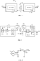
- FIG. 2 shows a simplified schematic diagram of a wireless power transfer system.
- the transmitter 104 includes an oscillator 122, a power amplifier 124 and a filter and matching circuit 126.
- the oscillator 122 is configured to generate at a desired frequency, such as 13.5 MHz, which may be adjusted in response to adjustment signal 123.
- An alternative uses LF frequencies, e.g., 135 Khz.
- the oscillator signal may be amplified by the power amplifier 124 with an amplification amount responsive to control signal 125.
- the filter and matching circuit 126 may be included to filter out harmonics or other unwanted frequencies and match the impedance of the transmitter 104 to the transmit antenna 114.
- the receiver 108 may include a matching circuit 132 and a rectifier and switching circuit 134 to generate a DC power output to charge a battery 136 as shown in FIG. 2 or power a device coupled to the receiver (not shown).
- the matching circuit 132 may be included to match the impedance of the receiver 108 to the receive antenna 118.
- antennas used in exemplary embodiments may be configured as a "loop" antenna 150, which may also be referred to herein as a "magnetic" antenna.
- Loop antennas may be configured to include an air core or a physical core such as a ferrite core. Using a ferrite core may decrease the effect of extraneous objects. However, ferrite cores may need a certain length to be effective, which may be difficult when used in a vehicle. Air disk coils are considered more suitable for integration in car and for embedding in the ground. LF Ferrites may be used as magnetic shield to prevent fields generating eddy currents in metallic parts of the antenna surrounding.
- Efficiency may be improved by keeping other devices outside of the core area.
- Air core loop antennas may be more tolerable to extraneous physical devices placed in the vicinity of the core. Furthermore, an air core loop antenna allows the placement of other components within the core area. In addition, an air core loop may more readily enable placement of the receive antenna 118 ( FIG. 2 ) within a plane of the transmit antenna 114 ( FIG. 2 ) where the coupled-mode region of the transmit antenna 114 ( FIG. 2 ) may be more powerful.
- the resonant frequency of the loop or magnetic antennas is based on the inductance and capacitance.
- Inductance in a loop antenna is generally simply the inductance created by the loop, whereas, capacitance is generally added to the loop antenna's inductance to create a resonant structure at a desired resonant frequency.
- capacitor 152 and capacitor 154 may be added to the antenna to create a resonant circuit that generates resonant signal 156. Accordingly, for larger diameter loop antennas, the size of capacitance needed to induce resonance decreases as the diameter or inductance of the loop increases. Furthermore, as the diameter of the loop or magnetic antenna increases, the efficient energy transfer area of the near-field increases.
- resonant circuits are possible.
- a capacitor may be placed in parallel between the two terminals of the loop antenna.
- the resonant signal 156 may be an input to the loop antenna 150.
- Exemplary embodiments of the invention include coupling power between two antennas that are in the near-fields of each other.
- the near-field is an area around the antenna in which electromagnetic fields exist but may not propagate or radiate away from the antenna. They are typically confined to a volume that is near the physical volume of the antenna.
- magnetic type antennas such as single and multi-turn loop antennas are used for both transmit (Tx) and receive (Rx) antenna systems because magnetic near-field amplitudes tend to be higher for magnetic type antennas in comparison to the electric near-fields of an electric-type antenna (e.g., a small dipole). This allows for potentially higher coupling between the pair.
- "electric" antennas e.g., dipoles and monopoles
- a combination of magnetic and electric antennas is also contemplated.
- the Tx antenna can be operated at a frequency that is low enough and with an antenna size that is large enough to achieve good coupling (e.g., >-4 dB) to a small Rx antenna at significantly larger distances than allowed by far field and inductive approaches mentioned earlier. If the Tx antenna is sized correctly, high coupling levels (e.g., -2 to -4 dB) can be achieved when the Rx antenna on a host device is placed within a coupling-mode region (i.e., in the near-field) of the driven Tx loop antenna.
- a coupling-mode region i.e., in the near-field
- Exemplary embodiments of the invention are directed to (or include) the following.
- Resonant charging is believed by the inventors to be the best way of charging because there is less heating and better efficiency for a same size coil. Accordingly, the exemplary embodiments describe a magnetically coupled system.
- the maximum transferable power depends on the size of the radiating structure (coil diameter), the coupling factor between primary and secondary, and the quality factor (Q-factor) of the primary and secondary.
- the applicable H-field strength limit at 135 kHz and for the given coil area is 57 dBuA/m at 10 m of distance, see European Norm EN 300330 (short range devices).
- Table 2 indicates the resulting r.m.s. currents and voltage in the primary coil.
- the Table 2 shows thousands of volts of voltage on the primary coil, thus demonstrating the high voltage within the coils. This can be challenging with respect to power/heat dissipation and withstanding voltage.
- Table 2 actually shows the so called median distance, which is the coil center to center distance, which is for a 1 cm thick coil of an exemplary embodiment. Accordingly, the actual distance between the surfaces of the coil is the distance in centimeters minus 1 cm. Therefore, the 1 cm distance in Table 2 is a value approaching zero: the smallest possible distance between the coils.
- Battery electric vehicles or "BEV”s are known to support a limited driving radius.
- An exemplar embodiment describes a wireless solution for recharging BEVs.
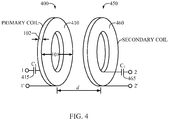
- An exemplary embodiment illustrated in Figure 4 forms a primary or transmitter 400 and a secondary or receiver 450.
- Each of the primary and the secondary uses disk-shaped coil of similar size.
- the primary coil 410 is a disk-shaped or 'pan cake' coil with its radial width larger than its axial width.
- the coils are dimensioned to handle high power and sustain the resulting high AC voltages and currents that will be produced, for example, those set forth in Table 2.
- the receive coil 460 has the same size and characteristics as the transmit coil. Coils may also be formed of insulated Litz wire.
- coil diameter should be as small as possible.
- the coils should be sufficiently large to handle the high power and to allow for some relative positioning error that will generally be present in vehicular applications.
- Resonance at the operating frequency is achieved by adding an appropriate value high-Q capacitor in series with the coils.
- Figure 4 shows capacitor 415 in series with transmit coil 410, and shows capacitor 465 in series with receive coil 460.
- both capacitors are dimensioned to withstand the high AC voltages set forth in Table 2.
- the primary coil 310 that delivers the charging power to the vehicle may be completely buried into the soil of a parking lot at a position corresponding to where the secondary coil 360 is likely to be on a vehicle.
- the primary coil By putting the primary coil in the ground, it can be run from a higher voltage, for example 220 V or 440 V.
- the coil is located so that vehicles of different size and length are properly parked when primary and secondary are coaxially aligned.
- Figures 5 and 6 show the arrangement where the BEV 500 has coil 360 mounted on a lifting mechanism 510 that controls lifting and lowering the coil.
- the operation may be controlled by a processor 520 in the vehicle 500. Once the coils are coaxially aligned and the primary is detected, the secondary 460 is lowered down to achieve close proximity coupling to the primary 410 as shown in Figure 5 . Then the processor may control initial tests to check coupling and efficiency of the power transfer between primary 410 and secondary 460. The tests can be used to adapt the link. Power transfer can start upon successful completion of these tests.
- Figure 6 illustrates how the vehicle 500 can park in any of the spaces 600, 610 and 620. Each of these spaces has an embedded and energized primary coil that can be used to charge the vehicle.
- An exemplary embodiment in Figure 7 may use a guidance system 700 to assist the driver (or an autopilot in case of an automatically driven vehicle) to accurately position the vehicle.
- the guidance system may rely on radio positioning principles using the LF or HF band.
- an exemplary embodiment may sense a degree of coupling between the primary 410 and secondary 460. The amount of coupling can be detected, for example by the vehicle receiving power from the primary.
- the guidance system can produce an output indicative of the degree, e.g., a sound or display.
- the vehicle-mounted subsystem may additionally provide an x-y offset control 800 for the secondary coil in another exemplary embodiment shown in Figure 8 .
- the guidance system would only be used for coarse positioning only, while the x-y offset control would adjust the fine alignment to allow better coupling between the coils.
- the exemplary embodiment of Figure 9 defines an alignment control 900 as part of the primary subsystem. This may provide x-y offset control that moves the primary coil 410.
- an array of primary coils 699 is used instead of a single coil.
- the array includes closely packed coils 700, 701, 702, 703, 704. While this exemplary embodiment shows five such coils, any number can be used between 3 and 15 coils, for example.
- a charging control 710 is connected by a switch box 720 to each of the coils. By testing coupling to a secondary, the charging control 710 selects the primary coil of the array 699 that is closest to the secondary 160.
- the secondary may also be aligned to the primary that is closest using the x-y offset control of the BEV as in the other exemplary embodiments.
- only one primary will be active for wireless charging once the link is established. All other primaries are deactivated. This exemplary embodiment may also use x-y control of the primaries, by allowing fine movement of these primaries to match the location of the secondary.
- Another exemplary embodiment describes a robotic vehicle that carriers the primary and which automatically moves below the vehicle to the position of the secondary.
- Another exemplary embodiment comprises a human presence detector that may be used to detect when a human is entering or exiting the vehicle.
- a human presence detector that may be used to detect when a human is entering or exiting the vehicle.
- This can use, for example, an infrared detection system that uses infrared sensors such as 215 located at various places near the vehicle.
- the infrared detection system detects heat of a type that is likely to represent a person, it outputs a signal indicative of the presence of a person.
- detection of a person causes the charging to terminate. This may alleviate certain fears that the magnetic charging is otherwise unhealthy.
- Another exemplary embodiment may include a circuit that automatically detects the field strength, for example, the FCC field strength and automatically maintains the values below the FFC limits.
- DSP Digital Signal Processor
- ASIC Application Specific Integrated Circuit
- FPGA Field Programmable Gate Array
- a general purpose processor may be a microprocessor, but in the alternative, the processor may be any conventional processor, controller, microcontroller, or state machine.
- a processor may also be implemented as a combination of computing devices, e.g., a combination of a DSP and a microprocessor, a plurality of microprocessors, one or more microprocessors in conjunction with a DSP core, or any other such configuration.
- a software module may reside in Random Access Memory (RAM), flash memory, Read Only Memory (ROM), Electrically Programmable ROM (EPROM), Electrically Erasable Programmable ROM (EEPROM), registers, hard disk, a removable disk, a CD-ROM, or any other form of storage medium known in the art.
- An exemplary storage medium is coupled to the processor such that the processor can read information from, and write information to, the storage medium.
- the storage medium may be integral to the processor.
- the processor and the storage medium may reside in an ASIC.
- the ASIC may reside in a user terminal.
- the processor and the storage medium may reside as discrete components in a user terminal.
- the functions described may be implemented in hardware, software, firmware, or any combination thereof. If implemented in software, the functions may be stored on or transmitted over as one or more instructions or code on a computer-readable medium.
- Computer-readable media includes both computer storage media and communication media including any medium that facilitates transfer of a computer program from one place to another.
- a storage media may be any available media that can be accessed by a computer.
- such computer-readable media can comprise RAM, ROM, EEPROM, CD-ROM or other optical disk storage, magnetic disk storage or other magnetic storage devices, or any other medium that can be used to carry or store desired program code in the form of instructions or data structures and that can be accessed by a computer.
- any connection is properly termed a computer-readable medium.
- the software is transmitted from a website, server, or other remote source using a coaxial cable, fiber optic cable, twisted pair, digital subscriber line (DSL), or wireless technologies such as infrared, radio, and microwave
- the coaxial cable, fiber optic cable, twisted pair, DSL, or wireless technologies such as infrared, radio, and microwave are included in the definition of medium.
- Disk and disc includes compact disc (CD), laser disc, optical disc, digital versatile disc (DVD), floppy disk and blu-ray disc where disks usually reproduce data magnetically, while discs reproduce data optically with lasers. Combinations of the above should also be included within the scope of computer-readable media.
Landscapes
- Engineering & Computer Science (AREA)
- Power Engineering (AREA)
- Transportation (AREA)
- Mechanical Engineering (AREA)
- Computer Networks & Wireless Communication (AREA)
- Charge And Discharge Circuits For Batteries Or The Like (AREA)
- Electric Propulsion And Braking For Vehicles (AREA)
- Current-Collector Devices For Electrically Propelled Vehicles (AREA)
- Secondary Cells (AREA)
Priority Applications (1)
| Application Number | Priority Date | Filing Date | Title |
|---|---|---|---|
| EP13151926.6A EP2584665B1 (en) | 2008-07-08 | 2009-07-08 | Wireless high power transfer under regulatory constraints |
Applications Claiming Priority (3)
| Application Number | Priority Date | Filing Date | Title |
|---|---|---|---|
| US7881208P | 2008-07-08 | 2008-07-08 | |
| US12/498,159 US8466654B2 (en) | 2008-07-08 | 2009-07-06 | Wireless high power transfer under regulatory constraints |
| PCT/US2009/049975 WO2010006078A1 (en) | 2008-07-08 | 2009-07-08 | Wireless high power transfer under regulatory constraints |
Related Child Applications (2)
| Application Number | Title | Priority Date | Filing Date |
|---|---|---|---|
| EP13151926.6A Division-Into EP2584665B1 (en) | 2008-07-08 | 2009-07-08 | Wireless high power transfer under regulatory constraints |
| EP13151926.6A Division EP2584665B1 (en) | 2008-07-08 | 2009-07-08 | Wireless high power transfer under regulatory constraints |
Publications (2)
| Publication Number | Publication Date |
|---|---|
| EP2301133A1 EP2301133A1 (en) | 2011-03-30 |
| EP2301133B1 true EP2301133B1 (en) | 2018-10-03 |
Family
ID=41211749
Family Applications (2)
| Application Number | Title | Priority Date | Filing Date |
|---|---|---|---|
| EP09790164.9A Active EP2301133B1 (en) | 2008-07-08 | 2009-07-08 | Wireless high power transfer under regulatory constraints |
| EP13151926.6A Active EP2584665B1 (en) | 2008-07-08 | 2009-07-08 | Wireless high power transfer under regulatory constraints |
Family Applications After (1)
| Application Number | Title | Priority Date | Filing Date |
|---|---|---|---|
| EP13151926.6A Active EP2584665B1 (en) | 2008-07-08 | 2009-07-08 | Wireless high power transfer under regulatory constraints |
Country Status (6)
| Country | Link |
|---|---|
| US (2) | US8466654B2 (ko) |
| EP (2) | EP2301133B1 (ko) |
| JP (3) | JP5329660B2 (ko) |
| KR (3) | KR101436712B1 (ko) |
| CN (2) | CN102089955B (ko) |
| WO (1) | WO2010006078A1 (ko) |
Families Citing this family (316)
| Publication number | Priority date | Publication date | Assignee | Title |
|---|---|---|---|---|
| US7825543B2 (en) | 2005-07-12 | 2010-11-02 | Massachusetts Institute Of Technology | Wireless energy transfer |
| US8169185B2 (en) | 2006-01-31 | 2012-05-01 | Mojo Mobility, Inc. | System and method for inductive charging of portable devices |
| US7952322B2 (en) | 2006-01-31 | 2011-05-31 | Mojo Mobility, Inc. | Inductive power source and charging system |
| US11201500B2 (en) | 2006-01-31 | 2021-12-14 | Mojo Mobility, Inc. | Efficiencies and flexibilities in inductive (wireless) charging |
| US7948208B2 (en) | 2006-06-01 | 2011-05-24 | Mojo Mobility, Inc. | Power source, charging system, and inductive receiver for mobile devices |
| US11329511B2 (en) | 2006-06-01 | 2022-05-10 | Mojo Mobility Inc. | Power source, charging system, and inductive receiver for mobile devices |
| US9421388B2 (en) | 2007-06-01 | 2016-08-23 | Witricity Corporation | Power generation for implantable devices |
| US8115448B2 (en) | 2007-06-01 | 2012-02-14 | Michael Sasha John | Systems and methods for wireless power |
| US20110050164A1 (en) | 2008-05-07 | 2011-03-03 | Afshin Partovi | System and methods for inductive charging, and improvements and uses thereof |
| CN102099958B (zh) | 2008-05-14 | 2013-12-25 | 麻省理工学院 | 包括干涉增强的无线能量传输 |
| US8441154B2 (en) | 2008-09-27 | 2013-05-14 | Witricity Corporation | Multi-resonator wireless energy transfer for exterior lighting |
| US8723366B2 (en) | 2008-09-27 | 2014-05-13 | Witricity Corporation | Wireless energy transfer resonator enclosures |
| US9396867B2 (en) | 2008-09-27 | 2016-07-19 | Witricity Corporation | Integrated resonator-shield structures |
| CN102239633B (zh) * | 2008-09-27 | 2017-01-18 | 韦特里西提公司 | 无线能量转移系统 |
| US8569914B2 (en) | 2008-09-27 | 2013-10-29 | Witricity Corporation | Wireless energy transfer using object positioning for improved k |
| US9544683B2 (en) | 2008-09-27 | 2017-01-10 | Witricity Corporation | Wirelessly powered audio devices |
| US9601270B2 (en) | 2008-09-27 | 2017-03-21 | Witricity Corporation | Low AC resistance conductor designs |
| US9601261B2 (en) | 2008-09-27 | 2017-03-21 | Witricity Corporation | Wireless energy transfer using repeater resonators |
| US8400017B2 (en) | 2008-09-27 | 2013-03-19 | Witricity Corporation | Wireless energy transfer for computer peripheral applications |
| US8552592B2 (en) * | 2008-09-27 | 2013-10-08 | Witricity Corporation | Wireless energy transfer with feedback control for lighting applications |
| US8471410B2 (en) | 2008-09-27 | 2013-06-25 | Witricity Corporation | Wireless energy transfer over distance using field shaping to improve the coupling factor |
| US9093853B2 (en) | 2008-09-27 | 2015-07-28 | Witricity Corporation | Flexible resonator attachment |
| US20100277121A1 (en) * | 2008-09-27 | 2010-11-04 | Hall Katherine L | Wireless energy transfer between a source and a vehicle |
| US8686598B2 (en) | 2008-09-27 | 2014-04-01 | Witricity Corporation | Wireless energy transfer for supplying power and heat to a device |
| US20120112691A1 (en) * | 2008-09-27 | 2012-05-10 | Kurs Andre B | Wireless energy transfer for vehicles |
| US8947186B2 (en) | 2008-09-27 | 2015-02-03 | Witricity Corporation | Wireless energy transfer resonator thermal management |
| US8669676B2 (en) | 2008-09-27 | 2014-03-11 | Witricity Corporation | Wireless energy transfer across variable distances using field shaping with magnetic materials to improve the coupling factor |
| US8946938B2 (en) | 2008-09-27 | 2015-02-03 | Witricity Corporation | Safety systems for wireless energy transfer in vehicle applications |
| US8587155B2 (en) * | 2008-09-27 | 2013-11-19 | Witricity Corporation | Wireless energy transfer using repeater resonators |
| US8772973B2 (en) | 2008-09-27 | 2014-07-08 | Witricity Corporation | Integrated resonator-shield structures |
| US8692412B2 (en) | 2008-09-27 | 2014-04-08 | Witricity Corporation | Temperature compensation in a wireless transfer system |
| US9106203B2 (en) | 2008-09-27 | 2015-08-11 | Witricity Corporation | Secure wireless energy transfer in medical applications |
| US8497601B2 (en) | 2008-09-27 | 2013-07-30 | Witricity Corporation | Wireless energy transfer converters |
| US8901778B2 (en) | 2008-09-27 | 2014-12-02 | Witricity Corporation | Wireless energy transfer with variable size resonators for implanted medical devices |
| US9515494B2 (en) | 2008-09-27 | 2016-12-06 | Witricity Corporation | Wireless power system including impedance matching network |
| US8907531B2 (en) | 2008-09-27 | 2014-12-09 | Witricity Corporation | Wireless energy transfer with variable size resonators for medical applications |
| US8957549B2 (en) | 2008-09-27 | 2015-02-17 | Witricity Corporation | Tunable wireless energy transfer for in-vehicle applications |
| US8922066B2 (en) | 2008-09-27 | 2014-12-30 | Witricity Corporation | Wireless energy transfer with multi resonator arrays for vehicle applications |
| US8482158B2 (en) | 2008-09-27 | 2013-07-09 | Witricity Corporation | Wireless energy transfer using variable size resonators and system monitoring |
| US8461722B2 (en) | 2008-09-27 | 2013-06-11 | Witricity Corporation | Wireless energy transfer using conducting surfaces to shape field and improve K |
| US9160203B2 (en) | 2008-09-27 | 2015-10-13 | Witricity Corporation | Wireless powered television |
| US9744858B2 (en) | 2008-09-27 | 2017-08-29 | Witricity Corporation | System for wireless energy distribution in a vehicle |
| US8937408B2 (en) | 2008-09-27 | 2015-01-20 | Witricity Corporation | Wireless energy transfer for medical applications |
| US9318922B2 (en) | 2008-09-27 | 2016-04-19 | Witricity Corporation | Mechanically removable wireless power vehicle seat assembly |
| US8629578B2 (en) | 2008-09-27 | 2014-01-14 | Witricity Corporation | Wireless energy transfer systems |
| US8928276B2 (en) | 2008-09-27 | 2015-01-06 | Witricity Corporation | Integrated repeaters for cell phone applications |
| US8304935B2 (en) * | 2008-09-27 | 2012-11-06 | Witricity Corporation | Wireless energy transfer using field shaping to reduce loss |
| US8324759B2 (en) * | 2008-09-27 | 2012-12-04 | Witricity Corporation | Wireless energy transfer using magnetic materials to shape field and reduce loss |
| US8410636B2 (en) | 2008-09-27 | 2013-04-02 | Witricity Corporation | Low AC resistance conductor designs |
| US8901779B2 (en) | 2008-09-27 | 2014-12-02 | Witricity Corporation | Wireless energy transfer with resonator arrays for medical applications |
| US8598743B2 (en) | 2008-09-27 | 2013-12-03 | Witricity Corporation | Resonator arrays for wireless energy transfer |
| US8643326B2 (en) | 2008-09-27 | 2014-02-04 | Witricity Corporation | Tunable wireless energy transfer systems |
| US8461721B2 (en) | 2008-09-27 | 2013-06-11 | Witricity Corporation | Wireless energy transfer using object positioning for low loss |
| US8963488B2 (en) | 2008-09-27 | 2015-02-24 | Witricity Corporation | Position insensitive wireless charging |
| US9065423B2 (en) | 2008-09-27 | 2015-06-23 | Witricity Corporation | Wireless energy distribution system |
| US8692410B2 (en) * | 2008-09-27 | 2014-04-08 | Witricity Corporation | Wireless energy transfer with frequency hopping |
| US9184595B2 (en) * | 2008-09-27 | 2015-11-10 | Witricity Corporation | Wireless energy transfer in lossy environments |
| US9577436B2 (en) | 2008-09-27 | 2017-02-21 | Witricity Corporation | Wireless energy transfer for implantable devices |
| US8587153B2 (en) | 2008-09-27 | 2013-11-19 | Witricity Corporation | Wireless energy transfer using high Q resonators for lighting applications |
| US8933594B2 (en) | 2008-09-27 | 2015-01-13 | Witricity Corporation | Wireless energy transfer for vehicles |
| US9035499B2 (en) | 2008-09-27 | 2015-05-19 | Witricity Corporation | Wireless energy transfer for photovoltaic panels |
| US9105959B2 (en) | 2008-09-27 | 2015-08-11 | Witricity Corporation | Resonator enclosure |
| US9601266B2 (en) | 2008-09-27 | 2017-03-21 | Witricity Corporation | Multiple connected resonators with a single electronic circuit |
| US9246336B2 (en) | 2008-09-27 | 2016-01-26 | Witricity Corporation | Resonator optimizations for wireless energy transfer |
| US8476788B2 (en) | 2008-09-27 | 2013-07-02 | Witricity Corporation | Wireless energy transfer with high-Q resonators using field shaping to improve K |
| US8487480B1 (en) | 2008-09-27 | 2013-07-16 | Witricity Corporation | Wireless energy transfer resonator kit |
| US8466583B2 (en) | 2008-09-27 | 2013-06-18 | Witricity Corporation | Tunable wireless energy transfer for outdoor lighting applications |
| US8461720B2 (en) * | 2008-09-27 | 2013-06-11 | Witricity Corporation | Wireless energy transfer using conducting surfaces to shape fields and reduce loss |
| US8912687B2 (en) | 2008-09-27 | 2014-12-16 | Witricity Corporation | Secure wireless energy transfer for vehicle applications |
| EP2345100B1 (en) | 2008-10-01 | 2018-12-05 | Massachusetts Institute of Technology | Efficient near-field wireless energy transfer using adiabatic system variations |
| BRPI0823235B1 (pt) | 2008-11-07 | 2019-04-24 | Toyota Jidosha Kabushiki Kaisha | Sistema de alimentação de energia para veículo e veículo eletricamente ativado. |
| CN101764434B (zh) * | 2008-12-22 | 2014-05-14 | 爱信艾达株式会社 | 受电引导装置 |
| DE102009013694A1 (de) * | 2009-03-20 | 2010-09-23 | Paul Vahle Gmbh & Co. Kg | Energieübertragungssystem mit mehreren Primärspulen |
| DE102009033239C5 (de) * | 2009-07-14 | 2023-05-17 | Conductix-Wampfler Gmbh | Vorrichtung zur induktiven Übertragung elektrischer Energie |
| RU2523708C2 (ru) * | 2009-08-19 | 2014-07-20 | Конинклейке Филипс Электроникс Н.В. | Электронное устройство и чашечная присоска, пригодная для такого электронного устройства |
| KR20110050831A (ko) * | 2009-11-09 | 2011-05-17 | 삼성전자주식회사 | 배터리 충전 시스템에서 무접점 충전을 지원하기 위한 장치 및 방법 |
| US20110133726A1 (en) * | 2009-12-09 | 2011-06-09 | Alexander Ballantyne | Precision alignment system |
| GB2488086B (en) * | 2010-01-05 | 2014-11-05 | Access Business Group Int Llc | Inductive charging system for electric vehicle |
| JP5526795B2 (ja) | 2010-01-15 | 2014-06-18 | ソニー株式会社 | ワイヤレス給電システム |
| JP2011188733A (ja) * | 2010-02-12 | 2011-09-22 | Semiconductor Energy Lab Co Ltd | 移動体、無線給電システムおよび無線給電方法 |
| JP4905571B2 (ja) * | 2010-03-10 | 2012-03-28 | トヨタ自動車株式会社 | 車両の駐車支援装置およびそれを備える車両 |
| CN106972642A (zh) * | 2010-03-10 | 2017-07-21 | 无线电力公司 | 无线能量转移转换器 |
| JP5051257B2 (ja) | 2010-03-16 | 2012-10-17 | トヨタ自動車株式会社 | 車両 |
| JP5290228B2 (ja) * | 2010-03-30 | 2013-09-18 | 株式会社日本自動車部品総合研究所 | 電圧検出器、異常検出装置、非接触送電装置、非接触受電装置、非接触給電システムおよび車両 |
| US9561730B2 (en) | 2010-04-08 | 2017-02-07 | Qualcomm Incorporated | Wireless power transmission in electric vehicles |
| US10343535B2 (en) * | 2010-04-08 | 2019-07-09 | Witricity Corporation | Wireless power antenna alignment adjustment system for vehicles |
| CN102858584B (zh) | 2010-04-21 | 2015-01-07 | 丰田自动车株式会社 | 车辆的停车支援装置和具有该装置的电动车辆 |
| MX2012012454A (es) * | 2010-04-26 | 2013-09-13 | Proterra Inc | Metodos y sistemas para la coleccion y carga automatica de un vehiculo electrico en una estacion de carga. |
| JP5139469B2 (ja) * | 2010-04-27 | 2013-02-06 | 株式会社日本自動車部品総合研究所 | コイルユニットおよび非接触給電システム |
| WO2011146661A2 (en) | 2010-05-19 | 2011-11-24 | Qualcomm Incorporated | Adaptive wireless energy transfer system |
| US8725330B2 (en) | 2010-06-02 | 2014-05-13 | Bryan Marc Failing | Increasing vehicle security |
| EP2580844A4 (en) | 2010-06-11 | 2016-05-25 | Mojo Mobility Inc | WIRELESS POWER TRANSFER SYSTEM SUPPORTING INTEROPERABILITY AND MULTIPOLAR MAGNETS FOR USE WITH THIS SYSTEM |
| CN103068618B (zh) * | 2010-07-29 | 2015-06-17 | 株式会社丰田自动织机 | 谐振型非接触电力供应系统 |
| US8482250B2 (en) * | 2010-08-06 | 2013-07-09 | Cynetic Designs Ltd. | Inductive transmission of power and data through ceramic armor panels |
| US9602168B2 (en) | 2010-08-31 | 2017-03-21 | Witricity Corporation | Communication in wireless energy transfer systems |
| US9385558B2 (en) * | 2010-10-01 | 2016-07-05 | Panasonic Intellectual Property Management Co., Ltd. | Electricity supply system for electric automobile, and electric automobile and power supply device used in said system |
| EP2632762B1 (en) | 2010-10-29 | 2017-05-31 | Qualcomm Incorporated(1/3) | Wireless energy transfer via coupled parasitic resonators |
| KR101318848B1 (ko) | 2010-12-01 | 2013-10-17 | 도요타 지도샤(주) | 비접촉 급전 설비, 차량 및 비접촉 급전 시스템의 제어 방법 |
| DE102010054848A1 (de) * | 2010-12-16 | 2012-06-21 | Conductix-Wampfler Ag | Vorrichtung zur induktiven Übertragung elektrischer Energie |
| US9379780B2 (en) * | 2010-12-16 | 2016-06-28 | Qualcomm Incorporated | Wireless energy transfer and continuous radio station signal coexistence |
| JP5348325B2 (ja) | 2010-12-24 | 2013-11-20 | トヨタ自動車株式会社 | 非接触充電システム、非接触充電方法、非接触充電型の車両、および非接触充電管理装置 |
| US9356659B2 (en) | 2011-01-18 | 2016-05-31 | Mojo Mobility, Inc. | Chargers and methods for wireless power transfer |
| US9496732B2 (en) | 2011-01-18 | 2016-11-15 | Mojo Mobility, Inc. | Systems and methods for wireless power transfer |
| US11342777B2 (en) | 2011-01-18 | 2022-05-24 | Mojo Mobility, Inc. | Powering and/or charging with more than one protocol |
| US9178369B2 (en) | 2011-01-18 | 2015-11-03 | Mojo Mobility, Inc. | Systems and methods for providing positioning freedom, and support of different voltages, protocols, and power levels in a wireless power system |
| US10115520B2 (en) | 2011-01-18 | 2018-10-30 | Mojo Mobility, Inc. | Systems and method for wireless power transfer |
| JP5218576B2 (ja) * | 2011-02-03 | 2013-06-26 | 株式会社デンソー | 非接触給電制御装置及び非接触給電システム |
| US9184633B2 (en) | 2011-02-03 | 2015-11-10 | Denso Corporation | Non-contact power supply control device, non-contact power supply system, and non-contact power charge system |
| EP2676827B1 (en) * | 2011-02-15 | 2019-03-27 | Toyota Jidosha Kabushiki Kaisha | Vehicle and external power supply device |
| EP2688181B1 (en) * | 2011-03-18 | 2018-12-26 | Yazaki Corporation | Power supply system |
| DE102011006504A1 (de) | 2011-03-31 | 2012-10-04 | Robert Bosch Gmbh | Verfahren zum Positionieren eines Kraftfahrzeugs |
| US10090885B2 (en) | 2011-04-13 | 2018-10-02 | Qualcomm Incorporated | Antenna alignment and vehicle guidance for wireless charging of electric vehicles |
| EP2709233B1 (en) * | 2011-05-12 | 2018-08-01 | IHI Corporation | Vehicle and non-contact power supply system |
| JP5737012B2 (ja) * | 2011-07-01 | 2015-06-17 | 富士通株式会社 | 電力供給システム、電力供給方法及び電力供給装置 |
| US9948145B2 (en) | 2011-07-08 | 2018-04-17 | Witricity Corporation | Wireless power transfer for a seat-vest-helmet system |
| US9379571B2 (en) * | 2011-07-11 | 2016-06-28 | Delphi Technologies, Inc. | Electrical charging system having energy coupling arrangement for wireless energy transmission therebetween |
| DE102011108386A1 (de) | 2011-07-22 | 2013-01-24 | Audi Ag | Verfahren zum Aufladen einer Traktionsbatterie, Vorrichtung zum Übertragen von Energie an ein Elektrofahrzeug und Kraftwagen |
| CN108418314A (zh) | 2011-08-04 | 2018-08-17 | 韦特里西提公司 | 可调谐无线电源架构 |
| US9631950B2 (en) | 2011-08-05 | 2017-04-25 | Evatran Group, Inc. | Method and apparatus for aligning a vehicle with an inductive charging system |
| US20130033228A1 (en) * | 2011-08-05 | 2013-02-07 | Evatran Llc | Method and apparatus for inductively transferring ac power between a charging unit and a vehicle |
| US20130038276A1 (en) * | 2011-08-11 | 2013-02-14 | Evatran Llc | Secondary coil structure of inductive charging system for electric vehicles |
| US20130037339A1 (en) * | 2011-08-12 | 2013-02-14 | Delphi Technologies, Inc. | Parking assist for a vehicle equipped with for wireless vehicle charging |
| IN2014CN01201A (ko) * | 2011-08-16 | 2015-04-10 | Nucleus Scient Inc | |
| KR101880258B1 (ko) | 2011-09-09 | 2018-07-19 | 위트리시티 코포레이션 | 무선 에너지 전송 시스템에서의 이물질 검출 |
| US20130062966A1 (en) | 2011-09-12 | 2013-03-14 | Witricity Corporation | Reconfigurable control architectures and algorithms for electric vehicle wireless energy transfer systems |
| CN103782487A (zh) * | 2011-09-13 | 2014-05-07 | 株式会社Ihi | 移动车辆供电系统 |
| JP5803475B2 (ja) * | 2011-09-16 | 2015-11-04 | 株式会社Ihi | 移動車両給電システム |
| DE102011114321A1 (de) | 2011-09-24 | 2013-03-28 | Volkswagen Aktiengesellschaft | Steckereinrichtung, Steckeraufnahme und System zur elektrischen Kopplung eines Fahrzeugs mit einer Ladestation sowie entsprechendes Verfahren |
| JP5665710B2 (ja) * | 2011-09-26 | 2015-02-04 | 株式会社東芝 | 無線電力伝送システム、送電装置及び受電装置 |
| DE102011083427A1 (de) * | 2011-09-26 | 2013-03-28 | Siemens Aktiengesellschaft | System zur Positionsbestimmung von zueinander beweglichen Objekten |
| JP5781882B2 (ja) * | 2011-09-29 | 2015-09-24 | トヨタ自動車株式会社 | 送電装置、車両および電力伝送システム |
| KR20130035905A (ko) * | 2011-09-30 | 2013-04-09 | 삼성전자주식회사 | 무선 충전 장치 및 방법 |
| US8816637B2 (en) * | 2011-10-06 | 2014-08-26 | Ford Global Technologies, Llc | Vehicle guidance system with interface |
| US8483899B2 (en) | 2011-10-06 | 2013-07-09 | Ford Global Technologies, Llc | Vehicle guidance system |
| US9318257B2 (en) | 2011-10-18 | 2016-04-19 | Witricity Corporation | Wireless energy transfer for packaging |
| DE102011116253B3 (de) * | 2011-10-18 | 2012-05-24 | Audi Ag | Fahrzeug mit Elektroantrieb mit Abschirmelement gegen elektromagnetische Strahlung |
| FR2981626B1 (fr) * | 2011-10-19 | 2013-12-20 | Peugeot Citroen Automobiles Sa | Procede d'aide au positionnement d'un vehicule electrique ou hybride |
| US9184598B2 (en) | 2011-10-26 | 2015-11-10 | Leggett & Platt Canada Co. | Signal discrimination for wireless key fobs and interacting systems |
| US9145110B2 (en) * | 2011-10-27 | 2015-09-29 | Ford Global Technologies, Llc | Vehicle wireless charger safety system |
| JP5700133B2 (ja) * | 2011-10-27 | 2015-04-15 | トヨタ自動車株式会社 | 非接触受電装置、非接触送電装置および非接触送受電システム |
| JP2015502729A (ja) | 2011-11-04 | 2015-01-22 | ワイトリシティ コーポレーションWitricity Corporation | 無線エネルギー伝送モデリングツール |
| JP5772535B2 (ja) * | 2011-11-18 | 2015-09-02 | トヨタ自動車株式会社 | 電力伝送システム及び車両 |
| WO2013076834A1 (ja) * | 2011-11-24 | 2013-05-30 | トヨタ自動車株式会社 | 送電装置、車両および非接触送受電システム |
| DE102012025785B3 (de) * | 2011-11-24 | 2020-01-09 | Avl Software And Functions Gmbh | Vorrichtung zur berührungslosen Energieübertragung, Leiterplatte mit einer Primärspulenanordnung und eine Ladestation |
| DE102011056807A1 (de) * | 2011-12-21 | 2013-06-27 | Thyssenkrupp Electrical Steel Gmbh | Magnetfeldabschirmung für elektromagnetische Felder und Fahrzeug mit integrierter Magnetfeldabschirmung |
| JP5829923B2 (ja) * | 2012-01-11 | 2015-12-09 | 小島プレス工業株式会社 | 非接触電力伝送システムの構成方法 |
| JP2015508987A (ja) | 2012-01-26 | 2015-03-23 | ワイトリシティ コーポレーションWitricity Corporation | 減少した場を有する無線エネルギー伝送 |
| US8933589B2 (en) | 2012-02-07 | 2015-01-13 | The Gillette Company | Wireless power transfer using separately tunable resonators |
| US9722447B2 (en) * | 2012-03-21 | 2017-08-01 | Mojo Mobility, Inc. | System and method for charging or powering devices, such as robots, electric vehicles, or other mobile devices or equipment |
| US9555716B2 (en) | 2012-03-21 | 2017-01-31 | Ford Global Technologies, Llc | Automotive vehicle charge system |
| US9796280B2 (en) | 2012-03-23 | 2017-10-24 | Hevo Inc. | Systems and mobile application for electric wireless charging stations |
| GB2500691B (en) * | 2012-03-30 | 2016-06-15 | Jaguar Land Rover Ltd | Charging system for a vehicle |
| EP2845290B1 (en) | 2012-05-03 | 2018-08-29 | Powermat Technologies Ltd. | System and method for triggering power transfer across an inductive power coupling and non resonant transmission |
| JP5348676B1 (ja) * | 2012-05-30 | 2013-11-20 | ニチユ三菱フォークリフト株式会社 | 充電システム |
| US9343922B2 (en) | 2012-06-27 | 2016-05-17 | Witricity Corporation | Wireless energy transfer for rechargeable batteries |
| US10992185B2 (en) | 2012-07-06 | 2021-04-27 | Energous Corporation | Systems and methods of using electromagnetic waves to wirelessly deliver power to game controllers |
| US9867062B1 (en) | 2014-07-21 | 2018-01-09 | Energous Corporation | System and methods for using a remote server to authorize a receiving device that has requested wireless power and to determine whether another receiving device should request wireless power in a wireless power transmission system |
| US10312715B2 (en) | 2015-09-16 | 2019-06-04 | Energous Corporation | Systems and methods for wireless power charging |
| US10965164B2 (en) | 2012-07-06 | 2021-03-30 | Energous Corporation | Systems and methods of wirelessly delivering power to a receiver device |
| US11502551B2 (en) | 2012-07-06 | 2022-11-15 | Energous Corporation | Wirelessly charging multiple wireless-power receivers using different subsets of an antenna array to focus energy at different locations |
| US10992187B2 (en) | 2012-07-06 | 2021-04-27 | Energous Corporation | System and methods of using electromagnetic waves to wirelessly deliver power to electronic devices |
| US9825674B1 (en) | 2014-05-23 | 2017-11-21 | Energous Corporation | Enhanced transmitter that selects configurations of antenna elements for performing wireless power transmission and receiving functions |
| US9876394B1 (en) | 2014-05-07 | 2018-01-23 | Energous Corporation | Boost-charger-boost system for enhanced power delivery |
| US10256657B2 (en) | 2015-12-24 | 2019-04-09 | Energous Corporation | Antenna having coaxial structure for near field wireless power charging |
| US9787103B1 (en) | 2013-08-06 | 2017-10-10 | Energous Corporation | Systems and methods for wirelessly delivering power to electronic devices that are unable to communicate with a transmitter |
| US10063105B2 (en) | 2013-07-11 | 2018-08-28 | Energous Corporation | Proximity transmitters for wireless power charging systems |
| US9859755B2 (en) | 2012-07-16 | 2018-01-02 | Qualcomm Incorporated | Device alignment and identification in inductive power transfer systems |
| US9654184B2 (en) * | 2012-07-20 | 2017-05-16 | WIPQTUS Inc. | Transmitter to receiver communication link in a wireless power system |
| US9287607B2 (en) | 2012-07-31 | 2016-03-15 | Witricity Corporation | Resonator fine tuning |
| DE102012213958A1 (de) * | 2012-08-07 | 2014-05-22 | Bayerische Motoren Werke Aktiengesellschaft | Fremdkörperüberwachung bei induktivem Laden |
| US9595378B2 (en) | 2012-09-19 | 2017-03-14 | Witricity Corporation | Resonator enclosure |
| JP6043462B2 (ja) * | 2012-09-27 | 2016-12-14 | Ihi運搬機械株式会社 | 車両給電装置 |
| US9465064B2 (en) | 2012-10-19 | 2016-10-11 | Witricity Corporation | Foreign object detection in wireless energy transfer systems |
| US11616520B2 (en) | 2012-11-09 | 2023-03-28 | California Institute Of Technology | RF receiver |
| US11843260B2 (en) | 2012-11-09 | 2023-12-12 | California Institute Of Technology | Generator unit for wireless power transfer |
| EP2917998A4 (en) | 2012-11-09 | 2016-07-20 | California Inst Of Techn | INTELLIGENT RF-LENSING: EFFICIENT, DYNAMIC AND MOBILE WIRELESS POWER TRANSMISSION |
| US9449757B2 (en) | 2012-11-16 | 2016-09-20 | Witricity Corporation | Systems and methods for wireless power system with improved performance and/or ease of use |
| US9515492B2 (en) * | 2012-12-06 | 2016-12-06 | Toyota Motor Engineering & Manufacturing North America, Inc. | Wireless power transfer using air gap and metamaterial |
| GB2510125B (en) * | 2013-01-24 | 2015-07-08 | Jaguar Land Rover Ltd | Vehicle charging method and apparatus |
| US8823551B1 (en) | 2013-03-07 | 2014-09-02 | Delphi Technologies, Inc. | System to align a vehicle within a parking location using thermal targets |
| KR102040739B1 (ko) * | 2013-03-20 | 2019-11-06 | 삼성전자주식회사 | 무선 전력 송수신 시스템 |
| FR3003815B1 (fr) * | 2013-03-27 | 2016-09-02 | Renault Sa | Procede pour la charge par induction d'une batterie electrique d'un vehicule automobile, station de charge, vehicule automobile et borne de charge associes |
| US9837846B2 (en) | 2013-04-12 | 2017-12-05 | Mojo Mobility, Inc. | System and method for powering or charging receivers or devices having small surface areas or volumes |
| WO2014174663A1 (ja) * | 2013-04-26 | 2014-10-30 | トヨタ自動車株式会社 | 受電装置、送電装置、電力伝送システム、および駐車支援装置 |
| JP5870957B2 (ja) * | 2013-04-26 | 2016-03-01 | トヨタ自動車株式会社 | 受電装置、駐車支援装置、車両および電力伝送システム |
| JP5857999B2 (ja) * | 2013-04-26 | 2016-02-10 | トヨタ自動車株式会社 | 受電装置、駐車支援装置、および電力伝送システム |
| DE102013208005A1 (de) | 2013-05-02 | 2014-11-06 | Bayerische Motoren Werke Aktiengesellschaft | Verfahren und Vorrichtung zum Betreiben einer kontaktlosen Ladeeinrichtung |
| FR3005612B1 (fr) | 2013-05-14 | 2016-11-18 | Schneider Electric Ind Sas | Dispositif de charge par induction de batteries d'un vehicule automobile electrique |
| DE102014208991A1 (de) * | 2013-05-15 | 2014-11-20 | Ford Global Technologies, Llc | Sicherheitssystem für drahtloses Fahrzeugaufladegerät |
| CN105340030B (zh) * | 2013-06-28 | 2018-11-16 | 西门子公司 | 感应式充电装置、电动车辆、充电站以及用于感应式充电的方法 |
| US9505314B2 (en) * | 2013-08-09 | 2016-11-29 | Qualcomm Incorporated | Systems, methods, and apparatus related to detecting and identifying electric vehicle and charging station |
| JP2016534698A (ja) | 2013-08-14 | 2016-11-04 | ワイトリシティ コーポレーションWitricity Corporation | インピーダンス同調 |
| JP6110758B2 (ja) * | 2013-08-26 | 2017-04-05 | 本田技研工業株式会社 | 車両誘導装置 |
| US9787099B2 (en) * | 2013-09-12 | 2017-10-10 | Kohler, Co. | Automatic diagnosis or repair for a generator controller |
| DE102013110280A1 (de) * | 2013-09-18 | 2015-03-19 | Paul Vahle Gmbh & Co. Kg | Positionsbestimmungssystem für Fahrzeuge |
| US9461500B2 (en) * | 2013-11-21 | 2016-10-04 | Htc Corporation | Wireless charging receiving device and wireless charging system using the same |
| CN103633697A (zh) * | 2013-11-22 | 2014-03-12 | 北京航空航天大学 | 电磁感应式非接触充电系统及其对准方法 |
| GB2520555B (en) * | 2013-11-26 | 2021-03-10 | Ford Global Tech Llc | A motor vehicle having an energy storage device |
| US10075028B2 (en) * | 2013-12-03 | 2018-09-11 | Utah State University | Determining physical alignment between magnetic couplers for wireless power transfer |
| GB2520990A (en) | 2013-12-06 | 2015-06-10 | Bombardier Transp Gmbh | Inductive power transfer for transferring electric energy to a vehicle |
| JP5979125B2 (ja) * | 2013-12-11 | 2016-08-24 | トヨタ自動車株式会社 | 非接触送電装置 |
| JP6156115B2 (ja) * | 2013-12-13 | 2017-07-05 | トヨタ自動車株式会社 | 送電装置 |
| US20150180264A1 (en) * | 2013-12-20 | 2015-06-25 | Cambridge Silicon Radio Limited | Antenna for wireless charging |
| JP6427873B2 (ja) * | 2013-12-20 | 2018-11-28 | 株式会社Ihi | 駐車支援装置及びシステム |
| JP6361132B2 (ja) | 2013-12-24 | 2018-07-25 | トヨタ自動車株式会社 | 非接触電力伝送システム、充電ステーション、および車両 |
| EP3117685B1 (en) * | 2014-01-30 | 2018-05-30 | Hewlett-Packard Development Company, L.P. | Wireless power alignment |
| US9780573B2 (en) | 2014-02-03 | 2017-10-03 | Witricity Corporation | Wirelessly charged battery system |
| US9952266B2 (en) | 2014-02-14 | 2018-04-24 | Witricity Corporation | Object detection for wireless energy transfer systems |
| US9772401B2 (en) * | 2014-03-17 | 2017-09-26 | Qualcomm Incorporated | Systems, methods, and apparatus for radar-based detection of objects in a predetermined space |
| JP6060330B2 (ja) * | 2014-03-24 | 2017-01-18 | トヨタ自動車株式会社 | 受電装置、車両、および送電装置 |
| JP6199789B2 (ja) * | 2014-03-31 | 2017-09-20 | Ihi運搬機械株式会社 | 非接触給電システムと車両給電装置 |
| DE102014206739A1 (de) * | 2014-04-08 | 2015-10-08 | Bayerische Motoren Werke Aktiengesellschaft | Schubfeld für einen Vorderwagen einer Fahrzeugkarosserie eines Fahrzeugs und Fahrzeug |
| WO2015161035A1 (en) | 2014-04-17 | 2015-10-22 | Witricity Corporation | Wireless power transfer systems with shield openings |
| US9842687B2 (en) | 2014-04-17 | 2017-12-12 | Witricity Corporation | Wireless power transfer systems with shaped magnetic components |
| US9837860B2 (en) | 2014-05-05 | 2017-12-05 | Witricity Corporation | Wireless power transmission systems for elevators |
| EP3140680B1 (en) | 2014-05-07 | 2021-04-21 | WiTricity Corporation | Foreign object detection in wireless energy transfer systems |
| US20150336464A1 (en) * | 2014-05-23 | 2015-11-26 | Ford Global Technologies, Llc | Ultrasonic location for electric vehicle charging system |
| US9463705B2 (en) * | 2014-06-10 | 2016-10-11 | Qualcomm Incorporated | System and method for adaptive charging compliance control |
| US9954375B2 (en) | 2014-06-20 | 2018-04-24 | Witricity Corporation | Wireless power transfer systems for surfaces |
| US10574091B2 (en) | 2014-07-08 | 2020-02-25 | Witricity Corporation | Enclosures for high power wireless power transfer systems |
| JP6518316B2 (ja) | 2014-07-08 | 2019-05-22 | ワイトリシティ コーポレーションWitricity Corporation | 無線電力伝送システムにおける共振器の均衡化 |
| CN104052137A (zh) * | 2014-07-08 | 2014-09-17 | 国家电网公司 | 一种大功率无线电力传输系统 |
| DE102014109893B4 (de) * | 2014-07-15 | 2019-10-31 | Paul Vahle Gmbh & Co. Kg | Bestimmung der Lage einer Pickup relativ zur Primäranordnung eines induktiven Energieübertragungssystems |
| KR20160021332A (ko) | 2014-08-14 | 2016-02-25 | 현대자동차주식회사 | 무선 충전 장치의 제어 방법 |
| WO2016028939A1 (en) | 2014-08-19 | 2016-02-25 | California Institute Of Technology | Wireless power transfer |
| US9649948B2 (en) * | 2014-08-25 | 2017-05-16 | Ford Global Technologies, Llc | Self-locating multi-coil system for wireless vehicle charging |
| US9889754B2 (en) * | 2014-09-09 | 2018-02-13 | Qualcomm Incorporated | System and method for reducing leakage flux in wireless electric vehicle charging systems |
| US9597971B2 (en) * | 2014-09-16 | 2017-03-21 | Qualcomm Incorporated | Methods and systems for compatible operation between a wireless power transfer system and vehicle remote entry systems |
| EP3198703A4 (en) * | 2014-09-28 | 2018-06-13 | Intel Corporation | Wireless charger coupling for electronic devices |
| DE102014114640A1 (de) * | 2014-10-09 | 2016-04-14 | Paul Vahle Gmbh & Co. Kg | Induktives Energieübertragungssystem mit breiter Primäranordnung |
| JP6550718B2 (ja) | 2014-10-28 | 2019-07-31 | トヨタ自動車株式会社 | 電力伝送システム |
| DE102014017544A1 (de) * | 2014-11-28 | 2016-06-02 | Sew-Eurodrive Gmbh & Co Kg | Verfahren und System zum induktiven Übertragen von elektrischer Energie an ein Fahrzeug |
| CN107148658B (zh) * | 2014-12-31 | 2020-01-21 | 麻省理工学院 | 无线电力传输的适应性控制 |
| CN104485723A (zh) * | 2014-12-31 | 2015-04-01 | 深圳市泰金田科技有限公司 | 电动汽车无线充电装置定位系统 |
| US9843217B2 (en) | 2015-01-05 | 2017-12-12 | Witricity Corporation | Wireless energy transfer for wearables |
| CN104648177B (zh) * | 2015-02-11 | 2016-09-21 | 吴宗群 | 一种汽车无线充电伸缩装置 |
| KR20160100755A (ko) * | 2015-02-16 | 2016-08-24 | 엘지이노텍 주식회사 | 무선전력 송신장치 및 송신방법 |
| JP6176272B2 (ja) * | 2015-02-27 | 2017-08-09 | トヨタ自動車株式会社 | 電力伝送システム |
| DE102015203796A1 (de) * | 2015-03-03 | 2016-09-08 | Siemens Aktiengesellschaft | Verwendung und Anordnung von Pencake-Spulen zur drahtlosen Energieübertragung an Elektrofahrzeuge |
| JP5931241B1 (ja) * | 2015-03-05 | 2016-06-08 | セイコーインスツル株式会社 | アンテナユニットおよび携帯型電子機器 |
| JP6172185B2 (ja) | 2015-03-11 | 2017-08-02 | トヨタ自動車株式会社 | 受電装置および送電装置 |
| US9845018B2 (en) | 2015-05-06 | 2017-12-19 | Toyota Motor Engineering & Manufacturing North America, Inc. | Self-aligning wireless power transfer |
| EP3103674B1 (de) | 2015-06-12 | 2021-08-18 | Brusa Elektronik AG | Positionsbestimmungssystem, verfahren zur positionsbestimmung und system zur induktiven energieübertragung mit positionsbestimmungssystem |
| US11710321B2 (en) | 2015-09-16 | 2023-07-25 | Energous Corporation | Systems and methods of object detection in wireless power charging systems |
| US10778041B2 (en) | 2015-09-16 | 2020-09-15 | Energous Corporation | Systems and methods for generating power waves in a wireless power transmission system |
| DE102015218410A1 (de) * | 2015-09-24 | 2017-03-30 | Continental Automotive Gmbh | Verfahren und Einrichtung zum Bestimmen der Absolutposition eines Fahrzeuges |
| DE102015218437A1 (de) | 2015-09-25 | 2017-03-30 | Bayerische Motoren Werke Aktiengesellschaft | Verfahren zur Herstellung einer Induktionsspule |
| WO2017062647A1 (en) | 2015-10-06 | 2017-04-13 | Witricity Corporation | Rfid tag and transponder detection in wireless energy transfer systems |
| US10734717B2 (en) | 2015-10-13 | 2020-08-04 | Energous Corporation | 3D ceramic mold antenna |
| EP3362804B1 (en) | 2015-10-14 | 2024-01-17 | WiTricity Corporation | Phase and amplitude detection in wireless energy transfer systems |
| WO2017070227A1 (en) | 2015-10-19 | 2017-04-27 | Witricity Corporation | Foreign object detection in wireless energy transfer systems |
| WO2017070009A1 (en) | 2015-10-22 | 2017-04-27 | Witricity Corporation | Dynamic tuning in wireless energy transfer systems |
| US10063108B1 (en) * | 2015-11-02 | 2018-08-28 | Energous Corporation | Stamped three-dimensional antenna |
| US10486538B2 (en) * | 2015-11-02 | 2019-11-26 | Hyundai America Technical Center, Inc. | Electromagnetic field controlling system and method for vehicle wireless charging system |
| US10075019B2 (en) | 2015-11-20 | 2018-09-11 | Witricity Corporation | Voltage source isolation in wireless power transfer systems |
| US11863001B2 (en) | 2015-12-24 | 2024-01-02 | Energous Corporation | Near-field antenna for wireless power transmission with antenna elements that follow meandering patterns |
| US10079515B2 (en) | 2016-12-12 | 2018-09-18 | Energous Corporation | Near-field RF charging pad with multi-band antenna element with adaptive loading to efficiently charge an electronic device at any position on the pad |
| US10038332B1 (en) | 2015-12-24 | 2018-07-31 | Energous Corporation | Systems and methods of wireless power charging through multiple receiving devices |
| US20170182903A1 (en) * | 2015-12-26 | 2017-06-29 | Intel Corporation | Technologies for wireless charging of electric vehicles |
| US10759281B2 (en) * | 2016-01-19 | 2020-09-01 | Ford Global Technologies, Llc | Controlling operation of electrified vehicle travelling on inductive roadway to influence electrical grid |
| CN105539186B (zh) * | 2016-01-20 | 2017-07-07 | 厦门新页科技有限公司 | 一种汽车无线充电对准匹配系统及方法 |
| EP3462574B1 (en) | 2016-02-02 | 2021-11-17 | WiTricity Corporation | Controlling wireless power transfer systems |
| KR102612384B1 (ko) | 2016-02-08 | 2023-12-12 | 위트리시티 코포레이션 | Pwm 커패시터 제어 |
| KR101887738B1 (ko) * | 2016-03-11 | 2018-08-10 | 현대자동차주식회사 | 무선 전력 전송 코일의 얼라인먼트 방법 및 이를 이용하는 장치 |
| DE102016205352A1 (de) | 2016-03-31 | 2017-10-05 | Bayerische Motoren Werke Aktiengesellschaft | Primärspuleneinheit |
| DE102016205711A1 (de) | 2016-04-06 | 2017-10-12 | Robert Bosch Gmbh | Verfahren zum Positionieren eines Kraftfahrzeugs |
| WO2017205878A1 (en) | 2016-05-27 | 2017-11-30 | Wireless Advanced Vehicle Electrification, Inc. | Checking alignment of inductive charge pads in motion |
| US10173542B2 (en) * | 2016-06-16 | 2019-01-08 | Ford Global Technologies, Llc | Wireless charging system coil alignment |
| KR102550114B1 (ko) * | 2016-06-16 | 2023-06-29 | 현대자동차주식회사 | 코일 정렬 방법 및 이를 이용하는 전기차 무선 전력 전송 장치 |
| TWI692422B (zh) * | 2016-06-21 | 2020-05-01 | 飛宏科技股份有限公司 | 具淹水監測之升降式充電裝置 |
| US10547208B2 (en) | 2016-06-23 | 2020-01-28 | Qualcomm Incorporated | Wireless power transmit resonator |
| KR101985490B1 (ko) * | 2016-07-25 | 2019-06-03 | 최봉호 | 무선 충전 디바이스 및 이를 이용한 차량 무선 충전 방법 |
| US10369894B2 (en) | 2016-10-21 | 2019-08-06 | Hevo, Inc. | Parking alignment sequence for wirelessly charging an electric vehicle |
| WO2018076214A1 (zh) * | 2016-10-26 | 2018-05-03 | 深圳市沃尔核材股份有限公司 | 无线充电线圈对准方法、装置及系统 |
| CN106541844B (zh) * | 2016-10-26 | 2020-04-10 | 深圳市沃尔核材股份有限公司 | 无线充电线圈对准方法、装置及系统 |
| US10923954B2 (en) | 2016-11-03 | 2021-02-16 | Energous Corporation | Wireless power receiver with a synchronous rectifier |
| KR102226403B1 (ko) | 2016-12-12 | 2021-03-12 | 에너저스 코포레이션 | 전달되는 무선 전력을 최대화하기 위한 근접장 충전 패드의 안테나 존들을 선택적으로 활성화시키는 방법 |
| US10439442B2 (en) | 2017-01-24 | 2019-10-08 | Energous Corporation | Microstrip antennas for wireless power transmitters |
| US10680319B2 (en) | 2017-01-06 | 2020-06-09 | Energous Corporation | Devices and methods for reducing mutual coupling effects in wireless power transmission systems |
| DE102017130173A1 (de) * | 2017-02-24 | 2018-08-30 | Denso Ten Limited | Ladeunterstützungsvorrichtung |
| US11011942B2 (en) | 2017-03-30 | 2021-05-18 | Energous Corporation | Flat antennas having two or more resonant frequencies for use in wireless power transmission systems |
| KR102027983B1 (ko) * | 2017-04-05 | 2019-10-04 | 한국전력공사 | 지상변압기를 이용한 전기차 충전 장치 및 전기차 충전 방법 |
| US11139686B2 (en) | 2017-04-13 | 2021-10-05 | Richard Marion Mansell | System and method for wireless transmission of power |
| US10829000B2 (en) | 2017-04-19 | 2020-11-10 | Arnold Chase | Remote control system for intelligent vehicle charging |
| US10128697B1 (en) | 2017-05-01 | 2018-11-13 | Hevo, Inc. | Detecting and deterring foreign objects and living objects at wireless charging stations |
| US11462949B2 (en) | 2017-05-16 | 2022-10-04 | Wireless electrical Grid LAN, WiGL Inc | Wireless charging method and system |
| CN107128201A (zh) * | 2017-05-25 | 2017-09-05 | 南京农业大学 | 一种耦合器单方向绕线的电动汽车无线充电装置 |
| CN107199901B (zh) * | 2017-05-25 | 2020-04-14 | 南京农业大学 | 一种法线式多线圈聚磁的电动汽车无线充电装置 |
| CN110999029A (zh) | 2017-05-30 | 2020-04-10 | 无线先进车辆电气化有限公司 | 单点馈电多垫式无线充电 |
| US10283952B2 (en) | 2017-06-22 | 2019-05-07 | Bretford Manufacturing, Inc. | Rapidly deployable floor power system |
| JP6527554B2 (ja) * | 2017-06-22 | 2019-06-05 | 本田技研工業株式会社 | 非接触電力伝送システム |
| US10848853B2 (en) | 2017-06-23 | 2020-11-24 | Energous Corporation | Systems, methods, and devices for utilizing a wire of a sound-producing device as an antenna for receipt of wirelessly delivered power |
| US11043848B2 (en) | 2017-06-29 | 2021-06-22 | Witricity Corporation | Protection and control of wireless power systems |
| JP6920123B2 (ja) * | 2017-07-18 | 2021-08-18 | 株式会社Subaru | 受電装置 |
| US10892632B2 (en) | 2017-08-15 | 2021-01-12 | Toyota Motor Engineering & Manufacturing North America, Inc. | Configurable grid charging coil with active switch and sensing system |
| US10668828B2 (en) | 2017-09-13 | 2020-06-02 | Toyota Motor Engineering & Manufacturing North America, Inc. | Multi-coil charging system for distributed in-wheel motors |
| US10850634B2 (en) * | 2017-10-20 | 2020-12-01 | Toyota Motor Engineering & Manufacturing North America, Inc. | Multi-turn configurable grid charging coil |
| US11342798B2 (en) | 2017-10-30 | 2022-05-24 | Energous Corporation | Systems and methods for managing coexistence of wireless-power signals and data signals operating in a same frequency band |
| CN111742464A (zh) | 2017-12-22 | 2020-10-02 | 无线先进车辆电气化有限公司 | 具有多个绕组的无线电力传输焊盘 |
| US11462943B2 (en) | 2018-01-30 | 2022-10-04 | Wireless Advanced Vehicle Electrification, Llc | DC link charging of capacitor in a wireless power transfer pad |
| US10562406B2 (en) * | 2018-03-12 | 2020-02-18 | Toyota Motor Engineering & Manufacturing North America, Inc. | System and method for autonomous charging of an autonomous vehicle |
| CN110525238A (zh) * | 2018-05-25 | 2019-12-03 | 比亚迪股份有限公司 | 用于轨道交通系统的无线充电系统和轨道交通系统 |
| US20210252986A1 (en) * | 2018-06-29 | 2021-08-19 | Brusa Elektronik Ag | Vehicle charging system for charging an energy store arranged in a vehicle |
| FR3084974B1 (fr) * | 2018-08-07 | 2021-10-29 | Commissariat Energie Atomique | Systeme de liaison electrique sans contact |
| CN109193958B (zh) * | 2018-09-13 | 2021-01-15 | 京东方科技集团股份有限公司 | 无线充电装置及其充电机构和电子系统 |
| US10988042B1 (en) | 2018-10-12 | 2021-04-27 | Arnold Chase | Vehicle charging system |
| US11437735B2 (en) | 2018-11-14 | 2022-09-06 | Energous Corporation | Systems for receiving electromagnetic energy using antennas that are minimally affected by the presence of the human body |
| KR20210117283A (ko) | 2019-01-28 | 2021-09-28 | 에너저스 코포레이션 | 무선 전력 전송을 위한 소형 안테나에 대한 시스템들 및 방법들 |
| US11444485B2 (en) | 2019-02-05 | 2022-09-13 | Mojo Mobility, Inc. | Inductive charging system with charging electronics physically separated from charging coil |
| EP3921945A1 (en) | 2019-02-06 | 2021-12-15 | Energous Corporation | Systems and methods of estimating optimal phases to use for individual antennas in an antenna array |
| US11329518B2 (en) * | 2019-06-24 | 2022-05-10 | Powermat Technologies Ltd. | Long-range wireless charging |
| DE102019209324A1 (de) * | 2019-06-27 | 2020-12-31 | Vitesco Technologies GmbH | Verfahren zum Positionieren eines Fahrzeugs über einer Bodenplatte zum induktiven Laden einer Fahrzeugbatterie |
| DE102019008519A1 (de) * | 2019-12-08 | 2021-06-10 | Tilman Röder | Verfahren zur induktiven Energieübertragung für einen oder mehrere mögliche Stromverbraucher oder Stromspeicher mit zielgerichteter Positionierung mindestens einer Senderspule oder einer Empfängerspule und ein entsprechendes induktives Energieübertragungssystem sowie zugehörige Vorrichtung. |
| DE102020100250A1 (de) | 2020-01-08 | 2021-07-08 | Audi Aktiengesellschaft | Ladevorrichtung und Empfangsvorrichtung zum induktiven Übertragen und Empfangen einer elektrischen Energie, Verfahren zum induktiven Übertragen und Empfangen einer elektrischen Energie, Ladesystem sowie Kraftfahrzeug mit einer Empfangsvorrichtung |
| CN112406569B (zh) * | 2020-11-05 | 2022-09-16 | 宁波赛耐比光电科技有限公司 | 一种无线充电桩的控制装置及其控制方法 |
| US11485246B1 (en) | 2021-04-05 | 2022-11-01 | Arnold Chase | Individualized vehicular charging mat |
Citations (5)
| Publication number | Priority date | Publication date | Assignee | Title |
|---|---|---|---|---|
| US5311973A (en) * | 1992-07-31 | 1994-05-17 | Ling-Yuan Tseng | Inductive charging of a moving electric vehicle's battery |
| FR2740921A1 (fr) * | 1995-11-06 | 1997-05-09 | Electricite De France | Dispositif automatise de charge des batteries d'un vehicule automobile a propulsion electrique |
| EP0788212A2 (en) * | 1996-01-30 | 1997-08-06 | Sumitomo Wiring Systems, Ltd. | Connection system and connection method for an electric automotive vehicle |
| US5661391A (en) * | 1994-06-23 | 1997-08-26 | Kabushiki Kaisha Toyoda Jidoshokki Seisakusho | Apparatus for charging a propulsion battery of an electrically powered vehicle |
| DE102007033654A1 (de) * | 2006-09-20 | 2008-04-24 | Sew-Eurodrive Gmbh & Co. Kg | System |
Family Cites Families (23)
| Publication number | Priority date | Publication date | Assignee | Title |
|---|---|---|---|---|
| US4331225A (en) | 1978-04-25 | 1982-05-25 | Bolger John G | Power control system for electrically driven vehicle |
| DE4235738A1 (de) * | 1992-10-23 | 1994-04-28 | Audi Ag | Endseitiger Abschluß eines Fahrzeuglängsträgers |
| DE4236286A1 (de) | 1992-10-28 | 1994-05-05 | Daimler Benz Ag | Verfahren und Anordnung zum automatischen berührungslosen Laden |
| US5573090A (en) * | 1994-05-05 | 1996-11-12 | H. R. Ross Industries, Inc. | Raodway-powered electric vehicle system having onboard power metering and communication channel features |
| JPH0833112A (ja) * | 1994-07-20 | 1996-02-02 | Sumitomo Electric Ind Ltd | 車両の非接触集電装置 |
| JPH08126120A (ja) | 1994-10-19 | 1996-05-17 | Yazaki Corp | 自動車の自動充電システム |
| JPH08237890A (ja) | 1995-02-28 | 1996-09-13 | Fuji Electric Co Ltd | 自動車への非接触式電力供給装置 |
| JP3586955B2 (ja) * | 1996-02-02 | 2004-11-10 | 住友電装株式会社 | 電気自動車用充電システム |
| JPH09213378A (ja) | 1996-01-30 | 1997-08-15 | Sumitomo Wiring Syst Ltd | 電気自動車用充電システム |
| US5821728A (en) * | 1996-07-22 | 1998-10-13 | Schwind; John P. | Armature induction charging of moving electric vehicle batteries |
| JPH10322247A (ja) * | 1997-05-21 | 1998-12-04 | Mitsubishi Electric Corp | ワイヤレス伝送装置 |
| GB9905539D0 (en) | 1999-03-10 | 1999-05-05 | Ea Tech Ltd | Battery chargers |
| US7064521B2 (en) * | 2001-08-17 | 2006-06-20 | O2Micro International Limited | Charging circuit for parallel charging in multiple battery systems |
| JP2004166384A (ja) * | 2002-11-12 | 2004-06-10 | Sharp Corp | 非接触型給電システムにおける電磁結合特性調整方法、給電装置、および非接触型給電システム |
| JP4442517B2 (ja) * | 2005-06-07 | 2010-03-31 | パナソニック電工株式会社 | 非接触給電装置及び自律移動装置用給電システム |
| US7825543B2 (en) * | 2005-07-12 | 2010-11-02 | Massachusetts Institute Of Technology | Wireless energy transfer |
| CN101258658B (zh) * | 2005-07-12 | 2012-11-14 | 麻省理工学院 | 无线非辐射能量传递 |
| JP2007159359A (ja) | 2005-12-08 | 2007-06-21 | Sumitomo Electric Ind Ltd | 電力転送システム、電力転送装置及び電力転送車載装置 |
| US7952322B2 (en) * | 2006-01-31 | 2011-05-31 | Mojo Mobility, Inc. | Inductive power source and charging system |
| JP2007294274A (ja) * | 2006-04-26 | 2007-11-08 | Matsushita Electric Ind Co Ltd | 二次電池包装体 |
| EP2078330A2 (en) * | 2006-10-25 | 2009-07-15 | Laszlo Farkas | High power wireless resonant energy transfer system transfers energy across an airgap |
| WO2008050260A1 (en) * | 2006-10-26 | 2008-05-02 | Philips Intellectual Property & Standards Gmbh | Inductive power system and method of operation |
| JP4691000B2 (ja) * | 2006-11-15 | 2011-06-01 | 三菱重工業株式会社 | 移動体の非接触給電装置 |
-
2009
- 2009-07-06 US US12/498,159 patent/US8466654B2/en active Active
- 2009-07-08 JP JP2011517578A patent/JP5329660B2/ja active Active
- 2009-07-08 CN CN200980126564.7A patent/CN102089955B/zh active Active
- 2009-07-08 EP EP09790164.9A patent/EP2301133B1/en active Active
- 2009-07-08 EP EP13151926.6A patent/EP2584665B1/en active Active
- 2009-07-08 KR KR1020127031675A patent/KR101436712B1/ko active IP Right Grant
- 2009-07-08 WO PCT/US2009/049975 patent/WO2010006078A1/en active Application Filing
- 2009-07-08 KR KR1020117002986A patent/KR20110026022A/ko not_active Application Discontinuation
- 2009-07-08 KR KR1020137025322A patent/KR101459254B1/ko not_active Application Discontinuation
- 2009-07-08 CN CN201410472151.7A patent/CN104283331B/zh active Active
-
2013
- 2013-06-17 US US13/919,835 patent/US8729859B2/en active Active
- 2013-07-24 JP JP2013153933A patent/JP2014039462A/ja not_active Withdrawn
-
2014
- 2014-10-29 JP JP2014220676A patent/JP6158159B2/ja active Active
Patent Citations (5)
| Publication number | Priority date | Publication date | Assignee | Title |
|---|---|---|---|---|
| US5311973A (en) * | 1992-07-31 | 1994-05-17 | Ling-Yuan Tseng | Inductive charging of a moving electric vehicle's battery |
| US5661391A (en) * | 1994-06-23 | 1997-08-26 | Kabushiki Kaisha Toyoda Jidoshokki Seisakusho | Apparatus for charging a propulsion battery of an electrically powered vehicle |
| FR2740921A1 (fr) * | 1995-11-06 | 1997-05-09 | Electricite De France | Dispositif automatise de charge des batteries d'un vehicule automobile a propulsion electrique |
| EP0788212A2 (en) * | 1996-01-30 | 1997-08-06 | Sumitomo Wiring Systems, Ltd. | Connection system and connection method for an electric automotive vehicle |
| DE102007033654A1 (de) * | 2006-09-20 | 2008-04-24 | Sew-Eurodrive Gmbh & Co. Kg | System |
Also Published As
| Publication number | Publication date |
|---|---|
| KR101459254B1 (ko) | 2014-11-12 |
| KR20130111647A (ko) | 2013-10-10 |
| JP2014039462A (ja) | 2014-02-27 |
| JP5329660B2 (ja) | 2013-10-30 |
| EP2584665B1 (en) | 2020-01-08 |
| EP2584665A3 (en) | 2013-05-15 |
| EP2301133A1 (en) | 2011-03-30 |
| CN102089955A (zh) | 2011-06-08 |
| KR20110026022A (ko) | 2011-03-14 |
| CN102089955B (zh) | 2014-10-22 |
| WO2010006078A1 (en) | 2010-01-14 |
| CN104283331B (zh) | 2017-12-05 |
| US8729859B2 (en) | 2014-05-20 |
| JP2015065805A (ja) | 2015-04-09 |
| US8466654B2 (en) | 2013-06-18 |
| JP2011527884A (ja) | 2011-11-04 |
| JP6158159B2 (ja) | 2017-07-05 |
| KR20130006706A (ko) | 2013-01-17 |
| CN104283331A (zh) | 2015-01-14 |
| US20100117596A1 (en) | 2010-05-13 |
| KR101436712B1 (ko) | 2014-09-02 |
| EP2584665A2 (en) | 2013-04-24 |
| US20130278210A1 (en) | 2013-10-24 |
Similar Documents
| Publication | Publication Date | Title |
|---|---|---|
| EP2301133B1 (en) | Wireless high power transfer under regulatory constraints | |
| US8288893B2 (en) | Adaptive matching and tuning of HF wireless power transmit antenna | |
| US8901880B2 (en) | Wireless power transmission for portable wireless power charging | |
| US10391871B2 (en) | Controlling current flow path in wireless electric vehicle charging systems for mitigating RF radiated emissions | |
| EP2571716B1 (en) | Adaptive wireless energy transfer system | |
| US8934857B2 (en) | Controlling field distribution of a wireless power transmitter | |
| KR20150038050A (ko) | 유도성 전력 전달 시스템들에서의 디바이스 정렬 및 식별 | |
| US20100109443A1 (en) | Wireless power transmission for electronic devices | |
| WO2012015839A2 (en) | Multi-loop wireless power receive coil | |
| US9240633B2 (en) | Tunable wireless power device | |
| US20110217926A1 (en) | Reverse link signaling via impedance modulation |
Legal Events
| Date | Code | Title | Description |
|---|---|---|---|
| PUAI | Public reference made under article 153(3) epc to a published international application that has entered the european phase |
Free format text: ORIGINAL CODE: 0009012 |
|
| 17P | Request for examination filed |
Effective date: 20110131 |
|
| AK | Designated contracting states |
Kind code of ref document: A1 Designated state(s): AT BE BG CH CY CZ DE DK EE ES FI FR GB GR HR HU IE IS IT LI LT LU LV MC MK MT NL NO PL PT RO SE SI SK SM TR |
|
| AX | Request for extension of the european patent |
Extension state: AL BA RS |
|
| DAX | Request for extension of the european patent (deleted) | ||
| 17Q | First examination report despatched |
Effective date: 20111214 |
|
| STAA | Information on the status of an ep patent application or granted ep patent |
Free format text: STATUS: EXAMINATION IS IN PROGRESS |
|
| RAP1 | Party data changed (applicant data changed or rights of an application transferred) |
Owner name: QUALCOMM INCORPORATED |
|
| GRAP | Despatch of communication of intention to grant a patent |
Free format text: ORIGINAL CODE: EPIDOSNIGR1 |
|
| STAA | Information on the status of an ep patent application or granted ep patent |
Free format text: STATUS: GRANT OF PATENT IS INTENDED |
|
| INTG | Intention to grant announced |
Effective date: 20180416 |
|
| GRAS | Grant fee paid |
Free format text: ORIGINAL CODE: EPIDOSNIGR3 |
|
| GRAA | (expected) grant |
Free format text: ORIGINAL CODE: 0009210 |
|
| STAA | Information on the status of an ep patent application or granted ep patent |
Free format text: STATUS: THE PATENT HAS BEEN GRANTED |
|
| AK | Designated contracting states |
Kind code of ref document: B1 Designated state(s): AT BE BG CH CY CZ DE DK EE ES FI FR GB GR HR HU IE IS IT LI LT LU LV MC MK MT NL NO PL PT RO SE SI SK SM TR |
|
| REG | Reference to a national code |
Ref country code: GB Ref legal event code: FG4D |
|
| REG | Reference to a national code |
Ref country code: CH Ref legal event code: EP Ref country code: AT Ref legal event code: REF Ref document number: 1049674 Country of ref document: AT Kind code of ref document: T Effective date: 20181015 |
|
| REG | Reference to a national code |
Ref country code: IE Ref legal event code: FG4D Ref country code: DE Ref legal event code: R096 Ref document number: 602009054880 Country of ref document: DE |
|
| REG | Reference to a national code |
Ref country code: NL Ref legal event code: MP Effective date: 20181003 |
|
| REG | Reference to a national code |
Ref country code: LT Ref legal event code: MG4D |
|
| REG | Reference to a national code |
Ref country code: AT Ref legal event code: MK05 Ref document number: 1049674 Country of ref document: AT Kind code of ref document: T Effective date: 20181003 |
|
| PG25 | Lapsed in a contracting state [announced via postgrant information from national office to epo] |
Ref country code: NL Free format text: LAPSE BECAUSE OF FAILURE TO SUBMIT A TRANSLATION OF THE DESCRIPTION OR TO PAY THE FEE WITHIN THE PRESCRIBED TIME-LIMIT Effective date: 20181003 |
|
| RAP2 | Party data changed (patent owner data changed or rights of a patent transferred) |
Owner name: WITRICITY CORPORATION |
|
| PG25 | Lapsed in a contracting state [announced via postgrant information from national office to epo] |
Ref country code: FI Free format text: LAPSE BECAUSE OF FAILURE TO SUBMIT A TRANSLATION OF THE DESCRIPTION OR TO PAY THE FEE WITHIN THE PRESCRIBED TIME-LIMIT Effective date: 20181003 Ref country code: PL Free format text: LAPSE BECAUSE OF FAILURE TO SUBMIT A TRANSLATION OF THE DESCRIPTION OR TO PAY THE FEE WITHIN THE PRESCRIBED TIME-LIMIT Effective date: 20181003 Ref country code: BG Free format text: LAPSE BECAUSE OF FAILURE TO SUBMIT A TRANSLATION OF THE DESCRIPTION OR TO PAY THE FEE WITHIN THE PRESCRIBED TIME-LIMIT Effective date: 20190103 Ref country code: AT Free format text: LAPSE BECAUSE OF FAILURE TO SUBMIT A TRANSLATION OF THE DESCRIPTION OR TO PAY THE FEE WITHIN THE PRESCRIBED TIME-LIMIT Effective date: 20181003 Ref country code: CZ Free format text: LAPSE BECAUSE OF FAILURE TO SUBMIT A TRANSLATION OF THE DESCRIPTION OR TO PAY THE FEE WITHIN THE PRESCRIBED TIME-LIMIT Effective date: 20181003 Ref country code: LT Free format text: LAPSE BECAUSE OF FAILURE TO SUBMIT A TRANSLATION OF THE DESCRIPTION OR TO PAY THE FEE WITHIN THE PRESCRIBED TIME-LIMIT Effective date: 20181003 Ref country code: NO Free format text: LAPSE BECAUSE OF FAILURE TO SUBMIT A TRANSLATION OF THE DESCRIPTION OR TO PAY THE FEE WITHIN THE PRESCRIBED TIME-LIMIT Effective date: 20190103 Ref country code: IS Free format text: LAPSE BECAUSE OF FAILURE TO SUBMIT A TRANSLATION OF THE DESCRIPTION OR TO PAY THE FEE WITHIN THE PRESCRIBED TIME-LIMIT Effective date: 20190203 Ref country code: ES Free format text: LAPSE BECAUSE OF FAILURE TO SUBMIT A TRANSLATION OF THE DESCRIPTION OR TO PAY THE FEE WITHIN THE PRESCRIBED TIME-LIMIT Effective date: 20181003 Ref country code: HR Free format text: LAPSE BECAUSE OF FAILURE TO SUBMIT A TRANSLATION OF THE DESCRIPTION OR TO PAY THE FEE WITHIN THE PRESCRIBED TIME-LIMIT Effective date: 20181003 Ref country code: LV Free format text: LAPSE BECAUSE OF FAILURE TO SUBMIT A TRANSLATION OF THE DESCRIPTION OR TO PAY THE FEE WITHIN THE PRESCRIBED TIME-LIMIT Effective date: 20181003 |
|
| PG25 | Lapsed in a contracting state [announced via postgrant information from national office to epo] |
Ref country code: SE Free format text: LAPSE BECAUSE OF FAILURE TO SUBMIT A TRANSLATION OF THE DESCRIPTION OR TO PAY THE FEE WITHIN THE PRESCRIBED TIME-LIMIT Effective date: 20181003 Ref country code: GR Free format text: LAPSE BECAUSE OF FAILURE TO SUBMIT A TRANSLATION OF THE DESCRIPTION OR TO PAY THE FEE WITHIN THE PRESCRIBED TIME-LIMIT Effective date: 20190104 Ref country code: PT Free format text: LAPSE BECAUSE OF FAILURE TO SUBMIT A TRANSLATION OF THE DESCRIPTION OR TO PAY THE FEE WITHIN THE PRESCRIBED TIME-LIMIT Effective date: 20190203 |
|
| REG | Reference to a national code |
Ref country code: DE Ref legal event code: R097 Ref document number: 602009054880 Country of ref document: DE |
|
| PG25 | Lapsed in a contracting state [announced via postgrant information from national office to epo] |
Ref country code: IT Free format text: LAPSE BECAUSE OF FAILURE TO SUBMIT A TRANSLATION OF THE DESCRIPTION OR TO PAY THE FEE WITHIN THE PRESCRIBED TIME-LIMIT Effective date: 20181003 Ref country code: DK Free format text: LAPSE BECAUSE OF FAILURE TO SUBMIT A TRANSLATION OF THE DESCRIPTION OR TO PAY THE FEE WITHIN THE PRESCRIBED TIME-LIMIT Effective date: 20181003 |
|
| PLBE | No opposition filed within time limit |
Free format text: ORIGINAL CODE: 0009261 |
|
| STAA | Information on the status of an ep patent application or granted ep patent |
Free format text: STATUS: NO OPPOSITION FILED WITHIN TIME LIMIT |
|
| PG25 | Lapsed in a contracting state [announced via postgrant information from national office to epo] |
Ref country code: EE Free format text: LAPSE BECAUSE OF FAILURE TO SUBMIT A TRANSLATION OF THE DESCRIPTION OR TO PAY THE FEE WITHIN THE PRESCRIBED TIME-LIMIT Effective date: 20181003 Ref country code: RO Free format text: LAPSE BECAUSE OF FAILURE TO SUBMIT A TRANSLATION OF THE DESCRIPTION OR TO PAY THE FEE WITHIN THE PRESCRIBED TIME-LIMIT Effective date: 20181003 Ref country code: SK Free format text: LAPSE BECAUSE OF FAILURE TO SUBMIT A TRANSLATION OF THE DESCRIPTION OR TO PAY THE FEE WITHIN THE PRESCRIBED TIME-LIMIT Effective date: 20181003 Ref country code: SM Free format text: LAPSE BECAUSE OF FAILURE TO SUBMIT A TRANSLATION OF THE DESCRIPTION OR TO PAY THE FEE WITHIN THE PRESCRIBED TIME-LIMIT Effective date: 20181003 |
|
| 26N | No opposition filed |
Effective date: 20190704 |
|
| PG25 | Lapsed in a contracting state [announced via postgrant information from national office to epo] |
Ref country code: SI Free format text: LAPSE BECAUSE OF FAILURE TO SUBMIT A TRANSLATION OF THE DESCRIPTION OR TO PAY THE FEE WITHIN THE PRESCRIBED TIME-LIMIT Effective date: 20181003 |
|
| PG25 | Lapsed in a contracting state [announced via postgrant information from national office to epo] |
Ref country code: MC Free format text: LAPSE BECAUSE OF FAILURE TO SUBMIT A TRANSLATION OF THE DESCRIPTION OR TO PAY THE FEE WITHIN THE PRESCRIBED TIME-LIMIT Effective date: 20181003 |
|
| REG | Reference to a national code |
Ref country code: CH Ref legal event code: PL |
|
| PG25 | Lapsed in a contracting state [announced via postgrant information from national office to epo] |
Ref country code: TR Free format text: LAPSE BECAUSE OF FAILURE TO SUBMIT A TRANSLATION OF THE DESCRIPTION OR TO PAY THE FEE WITHIN THE PRESCRIBED TIME-LIMIT Effective date: 20181003 |
|
| REG | Reference to a national code |
Ref country code: BE Ref legal event code: MM Effective date: 20190731 |
|
| PG25 | Lapsed in a contracting state [announced via postgrant information from national office to epo] |
Ref country code: CH Free format text: LAPSE BECAUSE OF NON-PAYMENT OF DUE FEES Effective date: 20190731 Ref country code: BE Free format text: LAPSE BECAUSE OF NON-PAYMENT OF DUE FEES Effective date: 20190731 Ref country code: LI Free format text: LAPSE BECAUSE OF NON-PAYMENT OF DUE FEES Effective date: 20190731 Ref country code: LU Free format text: LAPSE BECAUSE OF NON-PAYMENT OF DUE FEES Effective date: 20190708 |
|
| PG25 | Lapsed in a contracting state [announced via postgrant information from national office to epo] |
Ref country code: FR Free format text: LAPSE BECAUSE OF NON-PAYMENT OF DUE FEES Effective date: 20190731 |
|
| PG25 | Lapsed in a contracting state [announced via postgrant information from national office to epo] |
Ref country code: IE Free format text: LAPSE BECAUSE OF NON-PAYMENT OF DUE FEES Effective date: 20190708 |
|
| PG25 | Lapsed in a contracting state [announced via postgrant information from national office to epo] |
Ref country code: CY Free format text: LAPSE BECAUSE OF FAILURE TO SUBMIT A TRANSLATION OF THE DESCRIPTION OR TO PAY THE FEE WITHIN THE PRESCRIBED TIME-LIMIT Effective date: 20181003 |
|
| PG25 | Lapsed in a contracting state [announced via postgrant information from national office to epo] |
Ref country code: MT Free format text: LAPSE BECAUSE OF FAILURE TO SUBMIT A TRANSLATION OF THE DESCRIPTION OR TO PAY THE FEE WITHIN THE PRESCRIBED TIME-LIMIT Effective date: 20181003 Ref country code: HU Free format text: LAPSE BECAUSE OF FAILURE TO SUBMIT A TRANSLATION OF THE DESCRIPTION OR TO PAY THE FEE WITHIN THE PRESCRIBED TIME-LIMIT; INVALID AB INITIO Effective date: 20090708 |
|
| PG25 | Lapsed in a contracting state [announced via postgrant information from national office to epo] |
Ref country code: MK Free format text: LAPSE BECAUSE OF FAILURE TO SUBMIT A TRANSLATION OF THE DESCRIPTION OR TO PAY THE FEE WITHIN THE PRESCRIBED TIME-LIMIT Effective date: 20181003 |
|
| PGFP | Annual fee paid to national office [announced via postgrant information from national office to epo] |
Ref country code: GB Payment date: 20230727 Year of fee payment: 15 |
|
| PGFP | Annual fee paid to national office [announced via postgrant information from national office to epo] |
Ref country code: DE Payment date: 20230727 Year of fee payment: 15 |