EP2281650A1 - Automatikgetriebe für ein Elektrowerkzeug - Google Patents
Automatikgetriebe für ein Elektrowerkzeug Download PDFInfo
- Publication number
- EP2281650A1 EP2281650A1 EP10251330A EP10251330A EP2281650A1 EP 2281650 A1 EP2281650 A1 EP 2281650A1 EP 10251330 A EP10251330 A EP 10251330A EP 10251330 A EP10251330 A EP 10251330A EP 2281650 A1 EP2281650 A1 EP 2281650A1
- Authority
- EP
- European Patent Office
- Prior art keywords
- driven gear
- output shaft
- transmission
- transmission assembly
- speed
- Prior art date
- Legal status (The legal status is an assumption and is not a legal conclusion. Google has not performed a legal analysis and makes no representation as to the accuracy of the status listed.)
- Granted
Links
Images


Classifications
-
- B—PERFORMING OPERATIONS; TRANSPORTING
- B23—MACHINE TOOLS; METAL-WORKING NOT OTHERWISE PROVIDED FOR
- B23B—TURNING; BORING
- B23B45/00—Hand-held or like portable drilling machines, e.g. drill guns; Equipment therefor
- B23B45/008—Gear boxes, clutches, bearings, feeding mechanisms or like equipment
-
- B—PERFORMING OPERATIONS; TRANSPORTING
- B23—MACHINE TOOLS; METAL-WORKING NOT OTHERWISE PROVIDED FOR
- B23D—PLANING; SLOTTING; SHEARING; BROACHING; SAWING; FILING; SCRAPING; LIKE OPERATIONS FOR WORKING METAL BY REMOVING MATERIAL, NOT OTHERWISE PROVIDED FOR
- B23D47/00—Sawing machines or sawing devices working with circular saw blades, characterised only by constructional features of particular parts
- B23D47/12—Sawing machines or sawing devices working with circular saw blades, characterised only by constructional features of particular parts of drives for circular saw blades
-
- B—PERFORMING OPERATIONS; TRANSPORTING
- B23—MACHINE TOOLS; METAL-WORKING NOT OTHERWISE PROVIDED FOR
- B23D—PLANING; SLOTTING; SHEARING; BROACHING; SAWING; FILING; SCRAPING; LIKE OPERATIONS FOR WORKING METAL BY REMOVING MATERIAL, NOT OTHERWISE PROVIDED FOR
- B23D51/00—Sawing machines or sawing devices working with straight blades, characterised only by constructional features of particular parts; Carrying or attaching means for tools, covered by this subclass, which are connected to a carrier at both ends
- B23D51/16—Sawing machines or sawing devices working with straight blades, characterised only by constructional features of particular parts; Carrying or attaching means for tools, covered by this subclass, which are connected to a carrier at both ends of drives or feed mechanisms for straight tools, e.g. saw blades, or bows
-
- B—PERFORMING OPERATIONS; TRANSPORTING
- B25—HAND TOOLS; PORTABLE POWER-DRIVEN TOOLS; MANIPULATORS
- B25D—PERCUSSIVE TOOLS
- B25D16/00—Portable percussive machines with superimposed rotation, the rotational movement of the output shaft of a motor being modified to generate axial impacts on the tool bit
- B25D16/003—Clutches specially adapted therefor
-
- B—PERFORMING OPERATIONS; TRANSPORTING
- B25—HAND TOOLS; PORTABLE POWER-DRIVEN TOOLS; MANIPULATORS
- B25F—COMBINATION OR MULTI-PURPOSE TOOLS NOT OTHERWISE PROVIDED FOR; DETAILS OR COMPONENTS OF PORTABLE POWER-DRIVEN TOOLS NOT PARTICULARLY RELATED TO THE OPERATIONS PERFORMED AND NOT OTHERWISE PROVIDED FOR
- B25F5/00—Details or components of portable power-driven tools not particularly related to the operations performed and not otherwise provided for
- B25F5/001—Gearings, speed selectors, clutches or the like specially adapted for rotary tools
Definitions
- the present invention relates to power tools, and more particularly to power tool transmissions.
- Some power tool transmissions are user-configurable to provide different speed outputs.
- an operator of a multi-speed drilling machine may configure the drilling machine for high speed operation or low speed operation by actuating a mode switch on the drilling machine.
- this requires that the drilling machine be stopped, i.e. the transmission is stopped, in order to actuate the mode switch to effect a change in the speed of operation. It may even require removal of the drilling machine drill bit from the work piece prior to stopping of the drilling machine to effect the change in speed of operation in order to prevent locking or snagging of the drill bit in the work piece.
- the load exerted on the circular saw machine is also to some degree dependent on the operator's actions. This is also true of other types of power tools including drilling machines, routers, jig saws, screwdrivers and reciprocating saws. Where an operator of a circular saw machine pushes the saw machine with high force, the loading on the saw machine is greatly increased over that where the operator has a light touch, namely the operator pushes the saw machine forward relatively lightly. This disparity in loading caused by the operator's actions is present even where operators exhibiting the different behaviours mentioned above are sawing identical material of identical thickness.
- a further issue affecting the loading exerted on a circular saw machine is disparities in harness of the material being sawed. Again, the same issue affects other types of power tools.
- the masonry may comprise layers of different hardness material that are encountered in succession. Consequently, even where an operator applies a steady, constant pressure to the drilling machine, the loading on the drill bit and thus on the machine's motor will be dependent to a degree on how hard the layer of material presently being drilled in the masonry is.
- knots in the wood are relatively harder than the remainder of the wood sheet and result in higher load being exerted on the saw blade and consequently on the motor of the circular saw machine.
- a single speed circular saw machine can be successfully used on most occasions to cut through a sheet of wood with knots, there is a tendency for the operator to exert greater force on the saw machine when the saw blade encounters a knot thus greatly increasing the load exerted on the machine's motor through a combination of the two effects of the operator's action in exerting a greater urging force and the change in hardness of the material presently being sawed.
- providing a power tool with a single speed of operation is disadvantageous in that it does not account for disparities in load exerted on the tool's motor through an operator's actions and/or through changes in the characteristics of the work piece being worked, e.g. changes in thickness, nature or type of material being worked. More particularly, providing a power tool with only a low speed, high torque mode of operation will frustrate a user when working with a work piece of a type that could be successfully worked using a high speed, low torque mode of operation. The converse is true when providing a power tool with only a high speed, low torque mode of operation.
- one solution is to provide the power tool with more than one speed of operation and a mode selection switch for changing the speed of operation to suit the task in hand.
- operators are apt to always select the highest speed of operation to complete a task as quickly as possible and to persevere with the task in hand at the selected speed of operation even when a mode change would be of benefit.
- the mode selection switches provided in known power tools require the power tool to be stopped before effecting a change of speed mode and operators are often reluctance to stop and make a speed change.
- An object of the invention is to obviate and/or mitigate to some degree problems associated with known power tools.
- a further object of the invention is to provide a transmission for a power tool that can change its speed of operation whilst the power tool, i.e. its transmission, is still operating.
- Another object of the invention is to provide a transmission for a power tool which automatically changes its speed of operation in response to a level of load being exerted on the power tool motor whilst the power tool continues to be operated.
- the invention provides a transmission assembly for a power tool comprising a first transmission path constituting a high speed transmission path and a second transmission path constituting a low speed transmission path. Driven gears of each transmission path are permanently driven during operation of the transmission.
- a controller is provided for disengaging the high speed transmission path in response to monitored operating current of an electric motor providing a driving torque to an input of the transmission. When disengaged, a driven gear of the high speed transmission path continues to be driven, but the driven gear is disengaged from an output of the transmission. Consequently, under these circumstances, the low speed transmission path is the 'active' transmission path providing a low speed, high torque drive to the transmission output.
- a clutch enables the low speed transmission path to operate at a lower speed than an output of the transmission assembly when the high speed transmission path is engaged and is providing a high speed, low torque drive to the transmission output.
- a transmission assembly for a power tool comprising: an input shaft powered by a motor; an output shaft powered by the input shaft via a gear train, the gear train comprising: a first driven gear on the output shaft defining a high speed operation of the transmission assembly; and a second driven gear on the output shaft defining a low speed of operation of the transmission assembly; a connector operable to perform one of engaging and disengaging the first driven gear from the output shaft, wherein, when the first driven gear is engaged with the output shaft, the transmission assembly operates at said high speed of operation, and wherein the second driven gear is coupled to the output shaft by an overrunning bearing which defines the low speed operation of the transmission assembly.
- a clutch mechanism of the overrunning bearing may define the low speed of operation.
- the second driven gear is mounted onto the output shaft by the overrunning bearing or overrunning clutch whereby a clutch mechanism of said overrunning bearing establishes the low speed of operation of the power tool transmission assembly.
- the first driven gear is disengaged, i.e. unlocked, from rotating with the output shaft and thus no longer delivers drive to the output shaft
- the transmission assembly slows from its high speed, low torque mode of operation.
- the clutch of the overrunning bearing enables drive to be delivered from the second driven gear to the output shaft to seamlessly establish the low speed, high torque mode of operation of the transmission assembly. This is advantageous in that the second driven gear can be constantly driven even when the transmission assembly is operating at its high speed of operation.
- the over running bearing allows the second driven gear to rotate at a speed of operation lower than that of the output shaft of the transmission assembly. Furthermore, by unlocking the first driven gear from rotating with the output shaft when changing to the low speed of operation enables the first driven gear to be constantly driven because the first driven gear can continue to rotate at said high speed, but is no longer delivering any drive to the output shaft. Consequently, the transmission assembly does not require the axial movement of meshing gears to effect a change in speed of operation as is often found in conventional transmissions.
- the change in speed of operation of the transmission assembly of the invention can be effected whilst the transmission assembly is operating and can be effected in either direction, namely changed from high speed to low speed of operation or changed from low speed to high speed of operation whilst the transmission assembly is operating. There is no requirement to stop the transmission of the power tool when effecting a change in the speed of operation in either direction.
- the connector may be manually operable to perform one of engaging and disengaging the first driven gear from the output shaft.
- the connector may have a lever or mode switch associated therewith which is accessible external to the housing of the power tool.
- the lever or mode switch may be manually manipulatable to cause the connector to move to lock or unlock the first driven gear from the output shaft thereby effecting a change in the speed of operation of the power tool transmission.
- the lever or mode switch may be ergonomically located such that an operator of the power tool can manually operate said lever or mode switch whilst operating the power tool to work on a work piece.
- the connector is automatically operable to perform one of engaging and disengaging the first driven gear from the output shaft.
- the connector may be automatically operable to perform one of engaging and disengaging the first driven gear from the output shaft in response to a load exerted on the output shaft.
- the transmission assembly may comprise a control mechanism for monitoring the load exerted on the output shaft by monitoring a current drawn by an electric motor driving the input shaft of the transmission assembly.
- the control mechanism may comprise: a controller operable to detect an operating current of the electric motor and to compare the operating current to a threshold current; and a solenoid electrically connected to the controller; wherein the connector is movable from a first position to a second position in response to one of energizing or de-energizing the solenoid.
- the initial state of operation of the power tool assembly is the high speed of operation, although it will be understood that this is not an essential feature of the transmission.
- the initial state could be arranged to be the low speed of operation.
- the power tool transmission is operated at the speed of operation that is best suited to the prevailing needs of the task at hand and thus reduces user frustration and reduces the possibility of a user overloading the power tool motor and damaging it or the tool bit or overloading or damaging the battery of a cordless power tool, for example.
- the controller may be operable to compare the operating current of the electric motor to first and second threshold currents, wherein the first threshold current is higher than the second threshold current, and wherein, when the operating current equals or exceeds the first threshold current, the connector is operated to disengage the first driven gear from the output shaft and, when the operating current is equal to or below the second threshold current, the connector is operated to engage the first driven gear to the output shaft.
- a difference between the first and second threshold currents may be selected as being of sufficient magnitude to prevent the connector being operated to successively disengage and engage the first driven gear to the output shaft within a short period of time
- the advantage of having a first, higher threshold to trigger a switch from the high speed of operation to the lower speed of operation than a second, lower threshold for triggering a change in the reverse direction, is to create a buffer zone between the thresholds that prevents' chatter', namely the successive switching between modes of operation during a short period of time that can occur where only a single threshold is used and the power tool load is hovering around the threshold.
- the first and second driven gears may be permanently (constantly) driven by respective driving gears, but the overrunning bearing allows the second driven gear to rotate more slowly than the output shaft when the transmission is operating at the high speed of operation and the connector, when operated to disengage the first driven gear from the output shaft, enables the first driven gear to rotate more quickly than the output shaft when the transmission assembly is operating at the low speed of operation.
- a transmission assembly for a power tool comprising: a first transmission path comprising a high speed transmission path; a second transmission path comprising a low speed transmission path; a controller for engaging or disengaging the high speed transmission path; and a clutch for enabling the low speed transmission path to operate at a lower speed than an output of the transmission assembly when the high speed transmission path is engaged.
- a power tool having a transmission assembly according to the invention.
- the power tool may comprise one of: a drill; a jig saw; a circular saw machine; a router; a screwdriver; and a reciprocating saw.
- a method of operating a power tool comprising: transferring torque from an electric motor through a transmission; detecting an operating current of the motor; comparing the operating current of the motor to a threshold current; automatically changing a speed of operation of the transmission whilst the transmission is operating when the operating current equals or exceeds the threshold current.
- the method may comprise comparing the operating current of the electric motor to first and second threshold currents, wherein the first threshold current is higher than the second threshold current, and wherein, when the operating current equals or exceeds the first threshold current, the speed of operation of the transmission is automatically changed from a high speed of operation to a low speed of operation and, when the operating current is equal to or below the second threshold current, the speed of operation of the transmission is automatically changed from the low speed of operation to the high speed of operation.
- a difference between the first and second threshold currents may be selected as being of sufficient magnitude to prevent the speed of operation of the transmission being automatically changed successively within a short period of time.
- the transmission may be provided with first and second driven gears which are permanently driven by respective driving gears, but an overrunning bearing which couples the second driven gear to an output shaft of the transmission allows the second driven gear to rotate more slowly than the output shaft when the transmission is operating at a high speed of operation and a connector for engaging or disengaging the first driven gear from the output shaft, when operated to disengage the first driven gear from the output shaft, enables the first driven gear to rotate more quickly than the output shaft when the transmission assembly is operating at a low speed of operation.
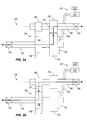
- the invention provides a manually operable transmission assembly 100 for a power tool comprising a first transmission path 110 constituting a high speed transmission path ( figure 1a ) and a second transmission path 120 constituting a low speed transmission path ( figure 1b ).
- the transmission assembly 100 comprises an input shaft 130 powered by a motor (not shown) and an output shaft 140 powered by the input shaft via a gear train 150.
- the gear train 150 comprises a first driving gear 152 mounted on the input shaft 130 which meshes with a first driven gear 154 on the output shaft 140.
- the gear ratio established by the first driving gear 152 and the first driven gear 154 defines a high speed operation of the transmission assembly 100.
- the gear train 150 also comprises a second driving gear 156 also mounted on the input shaft 130 which meshes with a second driven gear 158 on the output shaft 140.
- the gear ratio of the second driving gear and the second driven gear define a low speed of operation of the transmission assembly 100.
- the high speed of operation of the transmission assembly 100 is illustrated by the arrowed line 110 in figure 1a comprising drive received at the input shaft 130 from a motor of a power tool, the drive being conveyed via the first driving gear 152 to the first driven gear 154 and conveyed by said first driven gear 154 to said output shaft 140.
- the output shaft 140 delivers the drive at a high speed, low torque, relatively speaking, to a tool bit (not shown) mechanically coupled to the output shaft 140.
- the low speed of operation of the transmission assembly 100 is illustrated by the arrowed line 120 in figure 1b comprising drive received at the input shaft 140 from a motor of a power tool, the drive being conveyed via the second driving gear 156 to the second driven gear 158 and conveyed by said second driven gear 158 to said output shaft 140.
- the output shaft 140 delivers the drive at a low speed, high torque, relatively speaking, to a tool bit mechanically coupled to the output shaft 140.
- the input shaft 130 may have an input shaft mechanical device 160 or mechanism for coupling said shaft 130 to a shaft of a motor of a power tool to receive input drive torque from said motor.
- the input shaft 130 of the transmission assembly 100 may be integral with the motor shaft and thus comprise an extension of said motor shaft.
- the output shaft 140 delivers an output torque of the power tool to a tool bit such as a drill bit, saw blade, screwdriver bit or router bit.
- the output shaft 140 has an output shaft mechanical device or mechanism 170 for coupling a tool bit to the shaft 140.
- the nature of the output shaft mechanical device 170 depends on the type of power tool.
- the output shaft mechanical device 170 may comprise a drill chuck for receiving drill bits of various sizes. Rotational motion of the output shaft 140 is delivered through the drill chuck to a drill bit secured in the chuck.
- the output shaft mechanical device 170 may includes means for converting the rotational motion of the output shaft to a reciprocating motion to drive a jig saw blade secured in a tool bit holder of the output shaft mechanical device.
- the transmission assembly 100 includes a connector 180 operable to perform one of engaging and disengaging the first driven gear 154 from the output shaft 140.
- the connector 180 may comprise any means suitable for locking or fixing the first driven gear 154 to rotate with the output shaft 140 whereby drive torque received by the first driven gear 154 is transferred to the output shaft 140.
- the connector 180 may comprise a means for inserting/withdrawing a lock pin or pins between the first driven gear 154 and the output shaft 140 to lock/unlock said first driven gear 154 to said output shaft 140.
- the connector 180 is operable between two positions.
- a first position comprises a position at which the connector 180 fixes or locks the first driven gear 154 to the output shaft 140 whereas a second position comprises a position where the connector 180 releases or frees the first driven gear 154 from being locked or fixed to rotate with the output shaft 140.
- the first driven gear 154 In the second position of the connector 180, the first driven gear 154 is free to rotate independently of the output shaft 140. Consequently, when the first driven gear 154 is disengaged from the output shaft 140, the first driven gear 154 continues to be driven by the first driving gear 152 and therefore continues rotate at the high speed mode of operation, but no longer provides any drive torque to the output shaft 140.
- the transmission assembly 100 When the first driven gear 154 is disengaged from the output shaft 140, the transmission assembly 100 operates at said low speed of operation.
- the second driven gear 158 is mounted on the output shaft 140 by an overrunning bearing 190 which defines the low speed operation of the transmission assembly 100.
- the second driven gear 158 is pressed fitted on the overrunning bearing 190 which is, in turn, preferably press fitted onto the output shaft 140, although any suitable coupling means may be used.
- a clutch mechanism of the overrunning bearing enables the low speed transmission path 120 to operate at a lower speed than an output of the transmission assembly 100 without applying any drive to the output when the high speed transmission path is engaged and is providing a high speed, low torque drive to the transmission output in a usual or defined direction of operation of the transmission.
- the clutch mechanism of the overrunning bearing 190 allows the second driven gear 158 to rotate at a slower speed than the output shaft 140 in a defined direction, this being the defined direction of drive for the transmission assembly.
- the overrunning bearing 190 enables the second driven gear 158 to still be driven by the second driving gear 156 but not deliver any drive torque to the output shaft 140 because the output shaft 140 is being driven at a higher speed of rotation than that of the second driven gear 158.
- first and second driven gears 154, 158 of the two transmission paths 110, 120 are permanently driven during operation of the transmission.
- the transmission assembly 100 slows from its high speed, low torque mode of operation.
- the clutch of the overrunning bearing 190 enables drive to be delivered from the second driven gear 158 to the output shaft 140 to seamlessly establish the low speed, high torque mode of operation of the transmission assembly 100.
- the transmission assembly 100 does not require the axial or other movement of meshing gears relative to one another to effect a change in speed of operation as is often required in conventional transmissions.
- the change in speed of operation of the transmission assembly 100 of the invention can be effected whilst the transmission assembly 100 is operating and can be effected in either direction, namely changed from high speed to low speed of operation or changed from low speed to high speed of operation whilst the transmission assembly is operating. There is no requirement to stop the transmission of the power tool when effecting a change in the speed of operation in either direction, i.e. when stepping down the speed of operation or when stepping up the speed of operation.
- the connector 180 is manually operable to perform one of engaging and disengaging the first driven gear 154 from the output shaft 140.
- the connector 180 has a lever or mode switch 200 associated therewith which is accessible externally of a housing (not shown) of the power tool.
- the lever or mode switch 200 may be manually manipulatable to cause the connector 180 to move to lock or unlock the first driven gear 154 from the output shaft 140 thereby effecting a change in the speed of operation of the power tool transmission.
- the lever or mode switch 200 may be ergonomically located externally of the power tool such that an operator of the power tool can manually operate said lever or mode switch 200 whilst continuously operating the power tool to work on a work piece.
- the operator is not required to stop using the power tool to effect a change of speed of operation using the lever or mode switch 200.
- This offers distinct advantages over known power tools having mode selection switches to change a speed of operation where the power tool must be stopped to actuate the mode switch.
- the invention provides an automatically operable transmission assembly 100 for a power tool comprising a first transmission path 110 constituting a high speed transmission path ( figure 2a ) and a second transmission path 120 constituting a low speed transmission path ( figure 2b ).
- the transmission assembly 100 of this embodiment is generally the same as that for the embodiment of figures 1a and 1b and thus like numerals will be used to denote like parts.
- This embodiment differs, however, in that it automatically changes the speed of operation of the transmission assembly 100 in response to an amount of load exerted on the power tool motor.
- a control mechanism 210 is provided for causing the connector 180 to disengage the high speed transmission path 110 in response to monitored operating current of an electric motor providing a driving torque to an input of the transmission.
- a driven gear 154 of the high speed transmission path 110 continues to be driven, but the driven gear 154 is disengaged from an output of the transmission. Consequently, under these circumstances, the low speed transmission path 120 is the 'active' transmission path providing a low speed, high torque drive to the transmission output.
- the connector 180 is automatically operable to perform one of engaging and disengaging the first driven gear 154 from the output shaft 140 in response to a load exerted on the output shaft 140.
- the transmission assembly 100 includes the control mechanism 210 which is arranged to monitor the load exerted on the output shaft 140 by monitoring a current drawn by an electric motor driving the input shaft 130 of the transmission assembly 100.
- the control mechanism 210 comprises a controller 212 operable to detect an operating current of the electric motor and to compare the operating current to at least one threshold current.
- a solenoid 214 electrically connected to the controller 212; is provided to act on the lever or mode switch 200 to move the connector 180 from its first position to its second position in response to one of energizing or de-energizing the solenoid 214.
- the controller 212 may comprise a processor and a memory storing program instructions executable by the processor for implementing the steps of comparing the operating current of the motor to one or more threshold currents and to conveying control signals to the solenoid and/or associated power supply switching means for engerizing/de-energizing the solenoid.
- This arrangement is advantageous in that changes of speed of operation of the power tool occur automatically in response to monitored load on the power tool motor. Consequently, an operator of the power tool is not required to manually effect a change in speed of operation. Instead, the power tool's speed of operation is changed as required to account for, for example, the manner by which the operator is operating the power tool or the thickness and/or nature of the material being worked. Furthermore, the speed of operation is changed automatically whilst the transmission is operating and thus there is no requirement for an operator of the power tool to stop the power tool to facilitate a speed change.
- the controller 212 is preferably operable to compare the operating current of the electric motor to first and second threshold currents, wherein the first threshold current is higher than the second threshold current, and wherein, when the operating current equals or exceeds the first threshold current, the connector 180 is operated to disengage the first driven gear 154 from the output shaft 140. When the operating current is equal to or below the second threshold current, the connector 180 is operated to engage the first driven gear 154 to the output shaft 140. A difference between the first and second threshold currents is selected as being of sufficient magnitude to prevent the connector 180 being operated to successively disengage and engage the first driven gear 154 to the output shaft 140 within a short period of time.
- the advantage of having a first, higher threshold to trigger a switch from the high speed of operation to the lower speed of operation than a second, lower threshold for triggering a change in the reverse direction, is to create a buffer zone between the thresholds that prevents' chatter', namely the successive switching between modes of operation during a short period of time that can occur where only a single threshold is used and the power tool load is hovering around the single threshold.
- the initial state of operation of the power tool assembly is the high speed of operation, although it will be understood that this is not an essential feature of the transmission.
- the initial state could be arranged to be the low speed of operation.
- the power tool transmission is automatically operated at the speed of operation that is best suited to the prevailing needs of the task at hand and thus reduces user frustration and reduces the possibility of a user overloading the power tool motor and damaging it or the tool bit or overloading or damaging the battery of a cordless power tool, for example.
- the power tool having a transmission assembly may comprise one of: a drill; a jig saw; a circular saw machine; a router; a screwdriver; and a reciprocating saw, although the transmission assembly is applicable to any suitable power tool configuration.
- a method of operating a power tool having a transmission comprises transferring torque from an electric motor through the transmission assembly; detecting an operating current of the power tool motor, comparing the operating current of the motor to a threshold current, and automatically changing a speed of operation of the transmission assembly whilst the transmission assembly is operating when the operating current equals or exceeds the threshold current.
- the power tool 300 may be powered from an external power source via a power cord or may be battery powered.
- the power tool may include a power tool housing 302 that may receive the power cord or the battery pack.
- the power tool housing 302 may have a handle portion 304 and a drive portion 306.
- the drive portion 306 may include a motor 308, an output 310 and a drive train 312 located intermediate the motor 308 and the output 310.
- the drive train 312 may include a variable speed transmission to mechanically change the speed of the output.
- the power tool 300 may also include a trigger switch 314 and a motor switch 316 for selectively activating the motor to supply power to the drive train.
- the power tool may comprise a drilling machine or may comprise a jig saw, a router, a screwdriver or a reciprocating saw.
- the power tool 400 may be powered from an external power source via a power cord or may be battery powered.
- the power tool may include a power tool housing 402 that may receive the power cord or the battery pack.
- the power tool housing 402 may have a handle portion and a drive portion 406.
- the drive portion 406 may include a motor 408, an output 410 and a drive train 412 located intermediate the motor and the output.
- the drive train may include a variable speed transmission to mechanically change the speed of the output.
- the power tool may also include a trigger switch 414 and a motor switch 416 for selectively activating the motor to supply power to the drive train.
- the power tool may comprise a circular saw.
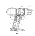
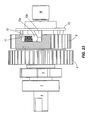
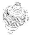
- Figure 8 illustrates in an exploded view the components comprising the transmission assembly 100 according to the invention.
- the transmission assembly 100 comprises a bearing 1 which mounts one end of the output shaft, i.e. spindle, 4 within the housing (not shown) of a power tool.
- the bearing 1 is preferably a roller bearing, although any suitable bearing or bushing may be utilized.
- An optional spacer 2 may be provided which sits on the spindle 4 between the bearing 1 and a manual spindle lock plate 3, although the spacer 2 and the manual spindle lock plate are not essential components of the transmission assembly.
- the manual spindle lock plate 3 enables an operator of the power tool to lock the spindle 4 to prevent rotation, but the spindle lock plate 3 is otherwise immaterial to the claimed invention.
- the spindle 4 comprises the transmission assembly output shaft.
- the spindle 4 may have a central collar 4a dividing the spindle into first and second end portions 4b, 4c.
- the bearing 1 supports a second end portion 4c of the spindle 4.
- Also mounted on this end portion 4c of the spindle 4 is the second driven gear 6 of the low speed, high torque transmission path of the transmission assembly.
- the second driven gear 6 is not directly mounted to the spindle 4 but is mounted thereon via an overrunning bearing or clutch 5.
- the overrunning bearing 5 is preferably press fitted on to the spindle 4 with the second driven gear 6 being preferably press fitted onto the overrunning bearing 5, although any suitable means of mounting the second driven gear 6 to the overrunning bearing 5 and the over running bearing 5 to the spindle 4 may be used. In operation, the overrunning bearing enables the second driven gear 6 to rotate more slowly than the spindle 4 in a defined direction.
- the over running bearing 5 comprises outer and inner ring members coupled via a clutch mechanism (not shown).
- a clutch mechanism (not shown).
- the outer ring rotates more slowly than the inner ring in a defined direction, there is no engagement via the clutch mechanism between the outer and inner rings, i.e. the outer ring is free to rotate at a slower speed than the inner ring in said defined direction.
- the clutch mechanism engages the outer ring to the inner ring to convey any driving force applied to the outer ring through to the inner ring.
- the transmission assembly is arranged such that the normal drive direction for the second driven gear coincides with the defined direction where the outer ring provides drive to the inner ring via the clutch mechanism when the outer ring is tending to go more quickly than the inner ring.
- a washer 7 may be proved which is located adjacent the collar 4a on the first end portion 4b of the spindle 4 and which acts to limit axial movement of the first driven gear 8 and lock pins 9.
- the first driven gear 8 is mounted on said first end portion 4b of the spindle 4.
- the connector of the transmission assembly comprises a cam plate 13 and a carrier 12.
- the carrier 12 is mounted on the spindle 4 so as to engage the first driven gear 8 and the cam plate 13 is mounted on the carrier 12 so as to engage the carrier 12.
- the cam plate 13 is movable axially along the spindle 4 with respect to the carrier 12.
- a plurality of lock pins 9 are provided on the carrier 12 which, when the cam plate is in a first position, lock or fix the first driven gear 8 for rotation with the spindle 4 and, when the cam plate 12 is in a second position, release or free the first driven gear 8 from the spindle 4 such that the first driven gear 8 can rotate independently of the spindle 4.
- the lock pins 9 are arranged to engage an inner surface of the first driven gear 8 when the carrier is in its first position in order to wedgedly fix its position with respect to the spindle 4 such that the first driven gear 8 rotates with the spindle 4, i.e. the first driven gear 8 conveys any driving force it receives to the spindle 4.
- the carrier 12 therefore functions to control the position of the lock pins 9.
- the carrier 12 is provided with a number of spring plates 10 which urge the lock pins into contact between the inner surface of the first driven gear 8 and the spindle 4 when the carrier 12 is in its first position.
- lock pins 9 Whilst a plurality of lock pins 9 is provided for fixing the position of the first driven gear 8 relative to the spindle 4, it will be understood that only one lock pin 9 may be required or some other suitable means could be employed for successively locking and releasing the first driven gear 8 from being fixed for rotation with the spindle 4.
- a set of three springs 11 is provided for urging the carrier 12 to rotate about the spindle 4 a short distance from its second position to its first position where the lock pins 9 are wedgedly fixing the position of the first driven gear 8 with respect to the spindle 4.
- the springs I 1 are located in respective recesses in the body of the first driven gear and act on respective front abutment surfaces of axially extending abutment members 12a of the carrier 12 which extend into said recesses to urge said carrier 12 towards its first position.
- the carrier 12 comprises a plastics material extruded member and the abutment members 12a are provided by integrally, extruded portions of the carrier 12, although the carrier may be formed from any other suitable material and need not comprise an integrally formed component.
- the cam plate 13 is arranged to move axially along a collar 12b of the carrier 12 such that respective wedge shaped cam members 13a of the cam plate 13 engage respective back abutment surfaces of the abutment members 12a of the carrier 12 and urge it towards its second position in opposition to the springs 11.
- the back abutment surfaces of the abutment members 12a are formed on opposite sides of said abutment members 12a to those comprising the front abutment surfaces.
- a rear washer 14 may be provided which limits axial movement of the cam plate 13 and carrier 12 on the first end portion 4b of the spindle 4.
- a retaining ring 15 may be provided to retain the washer 14.
- a bushing 16 is provided for supporting another end of the spindle 4 in the power tool housing.
- a speed change lever member 17 In order to effect axial movement of the cam plate 13 to cause rotation of the carrier 12 from its first to second positions, a speed change lever member 17 is provided.
- the speed change lever 17 has at one end a "C" shaped portion comprising first and second arms which each carry a respective bearing 18.
- the bearings 18 contact, in use, a rear surface of the cam plate 13 and act to guide the cam plate 13 between first and second axial positions on the spindle 4, said first axial position corresponding to the first position of the carrier 12 and said second axial position corresponding to the second position of the carrier 12.
- the cam plate 13 carried on the collar 12b of the carrier 12 is spaced from a rear flange of the carrier from which the abutment members 12a project by a small axial distance along the spindle 4 such that the carrier 12 is maintained in its first rotated position under the biasing action of the springs 11.
- the speed change lever 17 is used to urge the cam plate 13 axially along the collar 12b towards the carrier flange, the cam members 13a of the cam plate 13 engage the back abutment surfaces of the abutment members 12a of the carrier 12 to cause the carrier 12 to rotate against the biasing action of the springs 11 to its second position where the first driven gear 8 is released from being fixed to rotate with the spindle 4.
- another end of the speed change lever 17 is arranged to extend externally of a housing of the power tool to be accessible for manual operation.
- An operator could therefore change the speed of operation by simple manipulation of the lever 17, namely by moving it to effect axial movement of the cam plate 12 on the collar 12b of the carrier 12.
- the end of lever 17 would be positioned externally of the power tool housing at a position that is ergonomically suitable for easy access to an operator operating the power tool on a work piece or the like.
- the other end of the lever 17 is linked to a plunger 21 of a solenoid 23 via pin members 19, 20 which enable the lever 17 to pivot about pin member 19 whereby movement of the solenoid plunger 21 is transferred by the lever 17 to the cam plate 13 to causes axial movement of the cam plate 13 to engage the carrier 12 in the manner afore-described.
- a nut 22 or any other suitable means may be provided for mounting the solenoid to a gear transmission housing or other suitable housing part of the power tool.
- the solenoid 23 may be a pull type solenoid although any suitable solenoid may be employed.
- a pinion 25 comprises the input shaft of transmission assembly.
- the pinion 25 carries the first and second driving gears 25a, 25b of the power tool transmission.
- the first driving gear 25a permanently meshes with the first driven gear 8 whereas the second driving gear 25b permanently or constantly meshes with the second driven gear 6.
- a bushing 24 is provided for supporting one end of the pinion 25 in the power tool housing.
- the connector is operated to engage a driven gear of a transmission path with the spindle 4 to fix it for rotation in a defined direction through the wedging action of the lock pins 9 between an inner surface of the driven gear and an outer surface of the spindle 4.
- the driven gear urges the lock pins of the carrier 12 to further wedgedly engage the driven gear to the spindle 4 and thus drive provided to the driven gear is conveyed to the spindle 4 and the spindle 4 is driven at the operating speed of said transmission path.
- the connector arrangement as described with respect to figure 8 operates as and thus comprises an overrunning bearing or clutch.
- the driven gear of the low speed transmission path could be mounted to the output shaft by a connector generally as described above, but where it is maintained or established in an always operative position, i.e. the locks pins are urged to their wedgedly engaged position.
- a lever or mode switch as part of such a connector for the low speed transmission path as there would be no requirement to operate said connector to disengage the driven gear of the low speed transmission path from the spindle.
- the solenoid 23 is de-engerized with the plunger 21 being in an extended position with respect to the solenoid housing ( figure 21 ).
- the solenoid 23 pulls the plunger 21 to a non-extended position as can be best seen in figure 27 .
- the solenoid acts in a pull configuration.
- a push configuration solenoid could equally well be employed for effecting appropriate movement of the plunger.
- the solenoid 23 is arranged to be de-engerized when the plunger 21 is in its first, extended position with respect to the solenoid housing which corresponds to the first position of the carrier 12 effecting high speed operation of the transmission assembly, it will be understood that these are merely preferred arrangements and that alternative configurations apply.
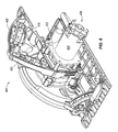
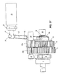
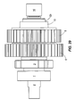
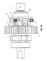
- Figures 9 to 17 illustrate the transmission assembly 100 of the invention assembled with a power tool motor 30. Like numerals to those used to denote the components of the transmission assembly with respect to figure 8 will be employed in figures 9 to 17 .
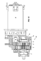
- Figures 18 to 32 illustrate the transmission assembly 100 and/or components of said transmission assembly 100. Like numerals to those used to denote the components of the transmission assembly 100 with respect to figure 8 will be employed in figures 18 to 32 .
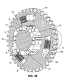
- Figures 18 to 20 show various views of the transmission assembly 100 with figures 19 and 20 showing partially cutaway views of said transmission assembly 100 illustrating the internal construction thereof.
- Figures 21 to 26 show various views of the transmission assembly and/or components of said assembly in a state representing the high speed mode of operation.
- the solenoid 23 in the high speed mode of operation, the solenoid 23 is de-engerized with the plunger 21 in its extended position relative to the solenoid housing. In this position, the plunger holds the lever 17 such that the cam plate 13 occupies its first position axially spaced from the carrier 12 (not shown) whereby the lock pins 9 (not shown) of the carrier 12 fix the first driven gear 8 for rotation with the spindle 4. Consequently, drive toque delivered by the first driving gear 25a to the first driven gear 8 is conveyed to the spindle and the transmission assembly operates at its high speed, low torque mode of operation.
- Figures 22 and 23 are views of the spindle 4 and driven gears 6, 8 part of the transmission assembly 100 with the first driven gear 8 partially cutaway to reveal the spatial relationship of the cam plate 13, carrier 12, springs 11 and first driven gear 8 in said high speed mode of operation. It can be seen that the cam plate 13 is positioned relative to the carrier 12 such that the wedge shaped cam members 13a of the cam plate are in contact at their forward ends with respective back abutment surfaces of respective abutment members 12a of the carrier.
- the springs 11 which, in use, bias the carrier 12 to its initial first position are located in recesses formed in the first driven gear 8 and arranged such that said springs act against front abutment surfaces of said abutment members 13a to urge the carrier 12 to its usual first position where the lock pins 9 (not shown) of the carrier engage an internal surface of the first driven gear 8 to fix it for rotation with the spindle 4.
- Axial movement of the cam plate 13 towards the carrier 12 causes the wedge shaped cam members 13a to more fully engage with the back abutment surfaces of the carrier abutment members 12a to cause said carrier to rotate towards its second position in a clockwise direction as seen in figures 22 and 23 against the biasing of the springs 11.
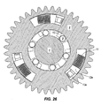
- Figure 24 is another view of the spindle 4 and driven gears 6, 8 part of the transmission assembly 100 with the first driven gear 8 removed to better illustrate the internal construction of the transmission assembly 100.
- the lock pins 9 are carried by the carrier 12 and, in the carrier's first position, wedgedly engage an inner surface of the first driven gear 8 and an outer surface of the spindle 4 to thereby fix the position of the first driven gear 8 with respect to the spindle 4 such that drive applied to the first driven gear 8 is conveyed to the spindle 4.
- Figure 25 is a perspective view of a part section of the first driven gear 8 and the carrier 12 and cam plate 13, also showing the cam plate 13 and carrier 12 in their respective first positions with respect to other components of the transmission assembly 100.
- Figure 26 is an end view corresponding to figure 25 . In this view, it can be seen that the lock pins 9 are wedgedly engaged between an inner surface of the first driven gear 8 and an outer surface of the spindle 4 and held in position by the spring plates 10 hich are also carried by the carrier 12.
- Figures 27 to 32 show various views of the transmission assembly 100 and/or components of said assembly in a state representing the low speed mode of operation.
- the solenoid 23 is engerized with the plunger 21 in its withdrawn or pulled in position relative to the solenoid housing.
- the plunger operates the lever 17 to pivot about pin 19 such that the lever causes the cam plate 13 to move axially towards the carrier 12 to occupy its first position axially adjacent to the carrier 12 (not shown) whereby the lock pins 9 (not shown) of the carrier 12 are freed from fixing the first driven gear 8 for rotation with the spindle 4.
- Figures 28 and 29 are views of the spindle 4 and driven gears 6, 8 part of the transmission assembly 100 with the first driven gear 8 partially cutaway to reveal the spatial relationship of the cam plate 13, carrier 12, springs 11 and first driven gear 8 in said low speed mode of operation.
- the cam plate 13 has been caused to move axially over the collar 12b of the carrier and in towards the carrier 12 such that said cam plate is adjacent the flange of the carrier 12.
- the wedge shaped cam members 13a of the cam plate contact with respective back abutment surfaces of respective abutment members 12a of the carrier at rearward points of front sloping edges of said cam members 13a.
- Figure 30 is another view of the spindle 4 and driven gears 6, 8 part of the transmission assembly 100 with the first driven gear 8 removed to better illustrate the internal construction of the transmission assembly 100 when the cam plate 13 and carrier 12 are in their second positions. In these positions, the lock pins 9 carried by the carrier 12 no longer wedgedly engage the inner surface of the first driven gear 8 and the outer surface of the spindle 4 and therefore the first driven gear 8 is free to rotate independently of the spindle 4.
- Figure 31 is a perspective view of a part section of the first driven gear 8 and the carrier 12 and cam plate 13, also showing the cam plate 13 and carrier 12 in their respective second positions with respect to other components of the transmission assembly 100.
- Figure 32 is an end view corresponding to figure 31 . In this view, it can be seen that the lock pins 9 are now located at a position relative to the first driven gear 8 where a gap or recess defined between the inner surface of the first driven gear and the outer surface of the spindle 4 is larger than a diameter of said lock pins such that the first driven gear 8 is no longer fixed to rotate with the spindle 4.
- the transmission assembly as described above can be adapted to have a high speed, low torque mode of operation, an intermediate speed, intermediate torque mode of operation, and a low speed, high torque mode of operation.
- Such an intermediate transmission path is similar in configuration to that of the afore-described high speed transmission path having a driving gear mounted on the input shaft of the transmission assembly arranged to mesh with and drive a further driven gear mounted on the output shaft.
- the ratio of the drive gear to the driven gear defines the intermediate speed of operation of this further transmission path.
- the driven gear of the intermediate transmission path also has a connector of the aforesaid type for engaging and disengaging the driven gear from the output shaft.
- the connector operates to engage the driven gear with the output shaft to fix it for rotation in a defined direction through the wedging action of the lock pins between an inner surface of the driven gear and an outer surface of the output shaft.
- the driven gear of the intermediate transmission path when the driven gear of the intermediate transmission path is being driven at a speed that is tending to exceed that of the output shaft (although it cannot actually exceed said speed), the driven gear pushes the lock pins of the carrier to wedgedly engage the driven gear to the output shaft and thus drive provided to the driven gear is conveyed to the output shaft and the output shaft is driven at the operating speed of the intermediate transmission path.
- the faster speed of the output shaft relative to the driven gear releases to a sufficient degree the wedged engagement of the lock pins between the driven gear and the output shaft such that the driven gear can slide relative to the output shaft, i.e.
- the transmission In operation, when both of the connectors of the high and intermediate speed transmission paths are operated to disengage their respective driven gears from the output shaft, the transmission operates at its low speed mode of operation as defined by the low speed transmission path having a driven gear mounted on the output shaft by an overrunning bearing or clutch.
- the driven gears of the high and intermediate speed transmission paths continue to be driven but neither conveys any drive to the output shaft as each of said driven gears rotates independently of the output shaft.
- Disengaging the respective driven gears of the high and intermediate speed transmission paths may be achieved by energizing respective solenoids arranged to actuate respective levers or mode switches of said transmission paths.
- the solenoids when energized, are arranged to actuate the levers or mode switches to move respective cam plates axially towards respective carriers thereby causing the respective connectors of said high and intermediate speed transmission paths to become disengaged from, i.e. to be no longer fixed for rotation with, the output shaft in the defined direction.
- the cam plate, carrier and connector arrangements for the high and intermediate speed transmission paths in this embodiment may have the same structure and configuration as the cam plate, carrier and connector arrangement described with respect to figures 1 to 32 .
- the intermediate speed mode of operation is selected by arranging for the connector of the intermediate transmission path to engage its driven gear with the output shaft and to arrange for the driven gear of the high speed transmission path to not be engaged with the output shaft. This may be achieved by energizing the solenoid of the high speed transmission path and de-energizing the solenoid of the intermediate speed transmission path.
- the overrunning bearing of the low speed transmission path allows the output shaft to rotate more quickly than the driven gear of the low speed transmission path which is permanently driven.
- the driven gear of the high speed transmission path rotates independently of the output shaft, whereas the driven gear of the intermediate speed transmission path, which is fixed for rotation by its respective connector with the output shaft in the defined direction, delivers drive to said output shaft at an intermediate speed and intermediate torque.
- the high speed mode of operation is selected by arranging for the connector of the high transmission path to engage its driven gear with the output shaft and to arrange for the driven gear of the intermediate speed transmission path to be engaged or remain engaged with the output shaft. This may be achieved by de- energizing the respective solenoids of the high and intermediate speed transmission.
- the driven gear of the intermediate speed transmission path continues to be driven, but is allowed to rotate at a slower speed than the output shaft through the clutch action of its connector, despite said connector being in its operative position that would normally fix the driven gear of the intermediate transmission path for rotation with the output shaft.
- the driven gear of the high speed transmission path which is now fixed for rotation by its respective connector with the output shaft in the defined direction, delivers drive to said output shaft at a high speed and low torque.
- the high, intermediate and low speed mode of operation could be automatically switched between in response to monitored load of the power tool motor, i.e. an operating current of the motor. Such automatic speed mode switching could be performed in connection with a respective current threshold for each mode of operation. Furthermore, it will be appreciated that changes of mode of operation between the high, intermediate and low speeds can be performed as before when the transmission is operating.
- the invention provides a transmission assembly for a power tool comprising a first transmission path constituting a high speed transmission path and a second transmission path constituting a low speed transmission path. Driven gears of each transmission path are permanently driven during operation of the transmission.
- a controller is provided for engaging or disengaging the high speed transmission path in response to monitored operating current of an electric motor providing a driving torque to an input of the transmission. When disengaged, a driven gear of the high speed transmission path continues to be driven, but the driven gear is disengaged from an output of the transmission. Consequently, under these circumstances, the low speed transmission path is the 'active' transmission path providing a low speed, high torque drive to the transmission output.
- a clutch enables the low speed transmission path to operate at a lower speed than an output of the transmission assembly when the high speed transmission path is engaged and is providing a high speed, low torque drive to the transmission output.
Applications Claiming Priority (1)
| Application Number | Priority Date | Filing Date | Title |
|---|---|---|---|
| US12/535,801 US8172004B2 (en) | 2009-08-05 | 2009-08-05 | Automatic transmission for a power tool |
Publications (2)
| Publication Number | Publication Date |
|---|---|
| EP2281650A1 true EP2281650A1 (de) | 2011-02-09 |
| EP2281650B1 EP2281650B1 (de) | 2016-01-06 |
Family
ID=42829305
Family Applications (1)
| Application Number | Title | Priority Date | Filing Date |
|---|---|---|---|
| EP10251330.6A Not-in-force EP2281650B1 (de) | 2009-08-05 | 2010-07-24 | Automatikgetriebe für ein Elektrowerkzeug |
Country Status (4)
| Country | Link |
|---|---|
| US (2) | US8172004B2 (de) |
| EP (1) | EP2281650B1 (de) |
| CN (1) | CN101994778B (de) |
| CA (1) | CA2712216C (de) |
Cited By (4)
| Publication number | Priority date | Publication date | Assignee | Title |
|---|---|---|---|---|
| WO2012175901A1 (en) * | 2011-06-20 | 2012-12-27 | Husqvarna Uk Limited | Speed control for power tools |
| EP2594368A1 (de) * | 2011-11-21 | 2013-05-22 | Panasonic Corporation | Geschwindigkeitsänderungsvorrichtung |
| CN103659749A (zh) * | 2012-09-13 | 2014-03-26 | 松下电器产业株式会社 | 电动工具 |
| DE112014003403B4 (de) * | 2013-07-24 | 2021-01-14 | Makita Corporation | Hin- und herbewegendes elektrisches Kraftwerkzeug |
Families Citing this family (429)
| Publication number | Priority date | Publication date | Assignee | Title |
|---|---|---|---|---|
| US20070084897A1 (en) | 2003-05-20 | 2007-04-19 | Shelton Frederick E Iv | Articulating surgical stapling instrument incorporating a two-piece e-beam firing mechanism |
| US9060770B2 (en) | 2003-05-20 | 2015-06-23 | Ethicon Endo-Surgery, Inc. | Robotically-driven surgical instrument with E-beam driver |
| US8215531B2 (en) | 2004-07-28 | 2012-07-10 | Ethicon Endo-Surgery, Inc. | Surgical stapling instrument having a medical substance dispenser |
| US11890012B2 (en) | 2004-07-28 | 2024-02-06 | Cilag Gmbh International | Staple cartridge comprising cartridge body and attached support |
| US7669746B2 (en) | 2005-08-31 | 2010-03-02 | Ethicon Endo-Surgery, Inc. | Staple cartridges for forming staples having differing formed staple heights |
| US10159482B2 (en) | 2005-08-31 | 2018-12-25 | Ethicon Llc | Fastener cartridge assembly comprising a fixed anvil and different staple heights |
| US7934630B2 (en) | 2005-08-31 | 2011-05-03 | Ethicon Endo-Surgery, Inc. | Staple cartridges for forming staples having differing formed staple heights |
| US9237891B2 (en) | 2005-08-31 | 2016-01-19 | Ethicon Endo-Surgery, Inc. | Robotically-controlled surgical stapling devices that produce formed staples having different lengths |
| US11246590B2 (en) | 2005-08-31 | 2022-02-15 | Cilag Gmbh International | Staple cartridge including staple drivers having different unfired heights |
| US8991676B2 (en) | 2007-03-15 | 2015-03-31 | Ethicon Endo-Surgery, Inc. | Surgical staple having a slidable crown |
| US11484312B2 (en) | 2005-08-31 | 2022-11-01 | Cilag Gmbh International | Staple cartridge comprising a staple driver arrangement |
| US20070106317A1 (en) | 2005-11-09 | 2007-05-10 | Shelton Frederick E Iv | Hydraulically and electrically actuated articulation joints for surgical instruments |
| US20110295295A1 (en) | 2006-01-31 | 2011-12-01 | Ethicon Endo-Surgery, Inc. | Robotically-controlled surgical instrument having recording capabilities |
| US8820603B2 (en) | 2006-01-31 | 2014-09-02 | Ethicon Endo-Surgery, Inc. | Accessing data stored in a memory of a surgical instrument |
| US8708213B2 (en) | 2006-01-31 | 2014-04-29 | Ethicon Endo-Surgery, Inc. | Surgical instrument having a feedback system |
| US7845537B2 (en) | 2006-01-31 | 2010-12-07 | Ethicon Endo-Surgery, Inc. | Surgical instrument having recording capabilities |
| US11278279B2 (en) | 2006-01-31 | 2022-03-22 | Cilag Gmbh International | Surgical instrument assembly |
| US20120292367A1 (en) | 2006-01-31 | 2012-11-22 | Ethicon Endo-Surgery, Inc. | Robotically-controlled end effector |
| US20110024477A1 (en) | 2009-02-06 | 2011-02-03 | Hall Steven G | Driven Surgical Stapler Improvements |
| US8186555B2 (en) | 2006-01-31 | 2012-05-29 | Ethicon Endo-Surgery, Inc. | Motor-driven surgical cutting and fastening instrument with mechanical closure system |
| US7753904B2 (en) | 2006-01-31 | 2010-07-13 | Ethicon Endo-Surgery, Inc. | Endoscopic surgical instrument with a handle that can articulate with respect to the shaft |
| US11793518B2 (en) | 2006-01-31 | 2023-10-24 | Cilag Gmbh International | Powered surgical instruments with firing system lockout arrangements |
| US11224427B2 (en) | 2006-01-31 | 2022-01-18 | Cilag Gmbh International | Surgical stapling system including a console and retraction assembly |
| US8992422B2 (en) | 2006-03-23 | 2015-03-31 | Ethicon Endo-Surgery, Inc. | Robotically-controlled endoscopic accessory channel |
| US8322455B2 (en) | 2006-06-27 | 2012-12-04 | Ethicon Endo-Surgery, Inc. | Manually driven surgical cutting and fastening instrument |
| US10568652B2 (en) | 2006-09-29 | 2020-02-25 | Ethicon Llc | Surgical staples having attached drivers of different heights and stapling instruments for deploying the same |
| US8220690B2 (en) | 2006-09-29 | 2012-07-17 | Ethicon Endo-Surgery, Inc. | Connected surgical staples and stapling instruments for deploying the same |
| US11291441B2 (en) | 2007-01-10 | 2022-04-05 | Cilag Gmbh International | Surgical instrument with wireless communication between control unit and remote sensor |
| US8684253B2 (en) | 2007-01-10 | 2014-04-01 | Ethicon Endo-Surgery, Inc. | Surgical instrument with wireless communication between a control unit of a robotic system and remote sensor |
| US8652120B2 (en) | 2007-01-10 | 2014-02-18 | Ethicon Endo-Surgery, Inc. | Surgical instrument with wireless communication between control unit and sensor transponders |
| US11039836B2 (en) | 2007-01-11 | 2021-06-22 | Cilag Gmbh International | Staple cartridge for use with a surgical stapling instrument |
| US20080169332A1 (en) | 2007-01-11 | 2008-07-17 | Shelton Frederick E | Surgical stapling device with a curved cutting member |
| US8893946B2 (en) | 2007-03-28 | 2014-11-25 | Ethicon Endo-Surgery, Inc. | Laparoscopic tissue thickness and clamp load measuring devices |
| US8931682B2 (en) | 2007-06-04 | 2015-01-13 | Ethicon Endo-Surgery, Inc. | Robotically-controlled shaft based rotary drive systems for surgical instruments |
| US11857181B2 (en) | 2007-06-04 | 2024-01-02 | Cilag Gmbh International | Robotically-controlled shaft based rotary drive systems for surgical instruments |
| US7753245B2 (en) | 2007-06-22 | 2010-07-13 | Ethicon Endo-Surgery, Inc. | Surgical stapling instruments |
| US11849941B2 (en) | 2007-06-29 | 2023-12-26 | Cilag Gmbh International | Staple cartridge having staple cavities extending at a transverse angle relative to a longitudinal cartridge axis |
| US7819298B2 (en) | 2008-02-14 | 2010-10-26 | Ethicon Endo-Surgery, Inc. | Surgical stapling apparatus with control features operable with one hand |
| US9179912B2 (en) | 2008-02-14 | 2015-11-10 | Ethicon Endo-Surgery, Inc. | Robotically-controlled motorized surgical cutting and fastening instrument |
| BRPI0901282A2 (pt) | 2008-02-14 | 2009-11-17 | Ethicon Endo Surgery Inc | instrumento cirúrgico de corte e fixação dotado de eletrodos de rf |
| US8636736B2 (en) | 2008-02-14 | 2014-01-28 | Ethicon Endo-Surgery, Inc. | Motorized surgical cutting and fastening instrument |
| US8573465B2 (en) | 2008-02-14 | 2013-11-05 | Ethicon Endo-Surgery, Inc. | Robotically-controlled surgical end effector system with rotary actuated closure systems |
| US7866527B2 (en) | 2008-02-14 | 2011-01-11 | Ethicon Endo-Surgery, Inc. | Surgical stapling apparatus with interlockable firing system |
| US8758391B2 (en) | 2008-02-14 | 2014-06-24 | Ethicon Endo-Surgery, Inc. | Interchangeable tools for surgical instruments |
| US10390823B2 (en) | 2008-02-15 | 2019-08-27 | Ethicon Llc | End effector comprising an adjunct |
| US11272927B2 (en) | 2008-02-15 | 2022-03-15 | Cilag Gmbh International | Layer arrangements for surgical staple cartridges |
| JP5435900B2 (ja) * | 2008-06-10 | 2014-03-05 | 株式会社マキタ | 丸鋸 |
| US8739417B2 (en) * | 2008-06-10 | 2014-06-03 | Makita Corporation | Circular saw |
| JP5017185B2 (ja) * | 2008-06-10 | 2012-09-05 | 株式会社マキタ | 動力工具 |
| JP5435899B2 (ja) * | 2008-06-10 | 2014-03-05 | 株式会社マキタ | 丸鋸 |
| CN102056714B (zh) * | 2008-06-10 | 2013-11-27 | 株式会社牧田 | 动力工具 |
| US9386983B2 (en) | 2008-09-23 | 2016-07-12 | Ethicon Endo-Surgery, Llc | Robotically-controlled motorized surgical instrument |
| US11648005B2 (en) | 2008-09-23 | 2023-05-16 | Cilag Gmbh International | Robotically-controlled motorized surgical instrument with an end effector |
| US8210411B2 (en) | 2008-09-23 | 2012-07-03 | Ethicon Endo-Surgery, Inc. | Motor-driven surgical cutting instrument |
| US9005230B2 (en) | 2008-09-23 | 2015-04-14 | Ethicon Endo-Surgery, Inc. | Motorized surgical instrument |
| US8608045B2 (en) | 2008-10-10 | 2013-12-17 | Ethicon Endo-Sugery, Inc. | Powered surgical cutting and stapling apparatus with manually retractable firing system |
| US8517239B2 (en) | 2009-02-05 | 2013-08-27 | Ethicon Endo-Surgery, Inc. | Surgical stapling instrument comprising a magnetic element driver |
| WO2010090940A1 (en) | 2009-02-06 | 2010-08-12 | Ethicon Endo-Surgery, Inc. | Driven surgical stapler improvements |
| US8444036B2 (en) | 2009-02-06 | 2013-05-21 | Ethicon Endo-Surgery, Inc. | Motor driven surgical fastener device with mechanisms for adjusting a tissue gap within the end effector |
| US8172004B2 (en) * | 2009-08-05 | 2012-05-08 | Techtronic Power Tools Technology Limited | Automatic transmission for a power tool |
| DE102009054927A1 (de) * | 2009-12-18 | 2011-06-22 | Robert Bosch GmbH, 70469 | Handwerkzeugmaschine, insbesondere Akkuhandwerkzeugmaschine |
| US8220688B2 (en) | 2009-12-24 | 2012-07-17 | Ethicon Endo-Surgery, Inc. | Motor-driven surgical cutting instrument with electric actuator directional control assembly |
| US8851354B2 (en) | 2009-12-24 | 2014-10-07 | Ethicon Endo-Surgery, Inc. | Surgical cutting instrument that analyzes tissue thickness |
| US8783543B2 (en) | 2010-07-30 | 2014-07-22 | Ethicon Endo-Surgery, Inc. | Tissue acquisition arrangements and methods for surgical stapling devices |
| CN102412558B (zh) * | 2010-09-26 | 2015-07-15 | 南京德朔实业有限公司 | 功率器件过温保护电路 |
| US11812965B2 (en) | 2010-09-30 | 2023-11-14 | Cilag Gmbh International | Layer of material for a surgical end effector |
| US9211120B2 (en) | 2011-04-29 | 2015-12-15 | Ethicon Endo-Surgery, Inc. | Tissue thickness compensator comprising a plurality of medicaments |
| US9320523B2 (en) | 2012-03-28 | 2016-04-26 | Ethicon Endo-Surgery, Llc | Tissue thickness compensator comprising tissue ingrowth features |
| US11298125B2 (en) | 2010-09-30 | 2022-04-12 | Cilag Gmbh International | Tissue stapler having a thickness compensator |
| US9629814B2 (en) | 2010-09-30 | 2017-04-25 | Ethicon Endo-Surgery, Llc | Tissue thickness compensator configured to redistribute compressive forces |
| US11849952B2 (en) | 2010-09-30 | 2023-12-26 | Cilag Gmbh International | Staple cartridge comprising staples positioned within a compressible portion thereof |
| US10945731B2 (en) | 2010-09-30 | 2021-03-16 | Ethicon Llc | Tissue thickness compensator comprising controlled release and expansion |
| US10213198B2 (en) | 2010-09-30 | 2019-02-26 | Ethicon Llc | Actuator for releasing a tissue thickness compensator from a fastener cartridge |
| US9364233B2 (en) | 2010-09-30 | 2016-06-14 | Ethicon Endo-Surgery, Llc | Tissue thickness compensators for circular surgical staplers |
| US9301755B2 (en) | 2010-09-30 | 2016-04-05 | Ethicon Endo-Surgery, Llc | Compressible staple cartridge assembly |
| US9517063B2 (en) | 2012-03-28 | 2016-12-13 | Ethicon Endo-Surgery, Llc | Movable member for use with a tissue thickness compensator |
| US8695866B2 (en) | 2010-10-01 | 2014-04-15 | Ethicon Endo-Surgery, Inc. | Surgical instrument having a power control circuit |
| CA2834649C (en) | 2011-04-29 | 2021-02-16 | Ethicon Endo-Surgery, Inc. | Staple cartridge comprising staples positioned within a compressible portion thereof |
| DE112011105222B4 (de) * | 2011-05-09 | 2018-08-23 | Zhengyang Technology Co., Ltd. | Vorrichtung zum automatischen Umschalten zwischen Vor- und Rückwärtsdrehung einer elektrischen Bohrmaschine |
| US11207064B2 (en) | 2011-05-27 | 2021-12-28 | Cilag Gmbh International | Automated end effector component reloading system for use with a robotic system |
| US9072535B2 (en) | 2011-05-27 | 2015-07-07 | Ethicon Endo-Surgery, Inc. | Surgical stapling instruments with rotatable staple deployment arrangements |
| US9039557B2 (en) * | 2011-09-02 | 2015-05-26 | Milwaukee Electric Tool Corporation | Powered dispensing tool |
| US8887831B2 (en) * | 2011-11-17 | 2014-11-18 | Black & Decker Inc. | Transmission for power tool with variable speed ratio |
| US9044230B2 (en) | 2012-02-13 | 2015-06-02 | Ethicon Endo-Surgery, Inc. | Surgical cutting and fastening instrument with apparatus for determining cartridge and firing motion status |
| JP6105041B2 (ja) | 2012-03-28 | 2017-03-29 | エシコン・エンド−サージェリィ・インコーポレイテッドEthicon Endo−Surgery,Inc. | 低圧環境を画定するカプセルを含む組織厚コンペンセーター |
| CN104321024B (zh) | 2012-03-28 | 2017-05-24 | 伊西康内外科公司 | 包括多个层的组织厚度补偿件 |
| JP6224070B2 (ja) | 2012-03-28 | 2017-11-01 | エシコン・エンド−サージェリィ・インコーポレイテッドEthicon Endo−Surgery,Inc. | 組織厚さコンペンセータを含む保持具アセンブリ |
| JP5841011B2 (ja) * | 2012-06-05 | 2016-01-06 | 株式会社マキタ | 回転打撃工具 |
| US9101358B2 (en) | 2012-06-15 | 2015-08-11 | Ethicon Endo-Surgery, Inc. | Articulatable surgical instrument comprising a firing drive |
| US20140005678A1 (en) | 2012-06-28 | 2014-01-02 | Ethicon Endo-Surgery, Inc. | Rotary drive arrangements for surgical instruments |
| US20140005718A1 (en) | 2012-06-28 | 2014-01-02 | Ethicon Endo-Surgery, Inc. | Multi-functional powered surgical device with external dissection features |
| US11202631B2 (en) | 2012-06-28 | 2021-12-21 | Cilag Gmbh International | Stapling assembly comprising a firing lockout |
| BR112014032776B1 (pt) | 2012-06-28 | 2021-09-08 | Ethicon Endo-Surgery, Inc | Sistema de instrumento cirúrgico e kit cirúrgico para uso com um sistema de instrumento cirúrgico |
| RU2636861C2 (ru) | 2012-06-28 | 2017-11-28 | Этикон Эндо-Серджери, Инк. | Блокировка пустой кассеты с клипсами |
| US9282974B2 (en) | 2012-06-28 | 2016-03-15 | Ethicon Endo-Surgery, Llc | Empty clip cartridge lockout |
| US9289256B2 (en) | 2012-06-28 | 2016-03-22 | Ethicon Endo-Surgery, Llc | Surgical end effectors having angled tissue-contacting surfaces |
| US20140001231A1 (en) | 2012-06-28 | 2014-01-02 | Ethicon Endo-Surgery, Inc. | Firing system lockout arrangements for surgical instruments |
| CN102744700A (zh) * | 2012-07-02 | 2012-10-24 | 南京德朔实业有限公司 | 冲击棘轮扳手 |
| JP6382235B2 (ja) | 2013-03-01 | 2018-08-29 | エシコン・エンド−サージェリィ・インコーポレイテッドEthicon Endo−Surgery,Inc. | 信号通信用の導電路を備えた関節運動可能な外科用器具 |
| RU2669463C2 (ru) | 2013-03-01 | 2018-10-11 | Этикон Эндо-Серджери, Инк. | Хирургический инструмент с мягким упором |
| US9629629B2 (en) | 2013-03-14 | 2017-04-25 | Ethicon Endo-Surgey, LLC | Control systems for surgical instruments |
| US9351726B2 (en) | 2013-03-14 | 2016-05-31 | Ethicon Endo-Surgery, Llc | Articulation control system for articulatable surgical instruments |
| US9801626B2 (en) | 2013-04-16 | 2017-10-31 | Ethicon Llc | Modular motor driven surgical instruments with alignment features for aligning rotary drive shafts with surgical end effector shafts |
| BR112015026109B1 (pt) | 2013-04-16 | 2022-02-22 | Ethicon Endo-Surgery, Inc | Instrumento cirúrgico |
| WO2015009850A1 (en) | 2013-07-19 | 2015-01-22 | Pro-Dex, Inc. | Torque-limiting screwdrivers |
| US9775609B2 (en) | 2013-08-23 | 2017-10-03 | Ethicon Llc | Tamper proof circuit for surgical instrument battery pack |
| MX369362B (es) | 2013-08-23 | 2019-11-06 | Ethicon Endo Surgery Llc | Dispositivos de retraccion de miembros de disparo para instrumentos quirurgicos electricos. |
| US9222528B2 (en) | 2013-09-11 | 2015-12-29 | Ingersoll-Rand Company | Overrunning clutches |
| DE102013021832A1 (de) * | 2013-12-21 | 2015-06-25 | Andreas Stihl Ag & Co. Kg | Verfahren zum Betrieb eines handgeführten Arbeitsgeräts mit einem Verbrennungsmotor |
| US9017209B1 (en) | 2013-12-31 | 2015-04-28 | Ingersoll-Rand Company | Power tools with reversible, self-shifting transmission |
| US9962161B2 (en) | 2014-02-12 | 2018-05-08 | Ethicon Llc | Deliverable surgical instrument |
| JP6462004B2 (ja) | 2014-02-24 | 2019-01-30 | エシコン エルエルシー | 発射部材ロックアウトを備える締結システム |
| BR112016021943B1 (pt) | 2014-03-26 | 2022-06-14 | Ethicon Endo-Surgery, Llc | Instrumento cirúrgico para uso por um operador em um procedimento cirúrgico |
| US9826977B2 (en) | 2014-03-26 | 2017-11-28 | Ethicon Llc | Sterilization verification circuit |
| US20150272571A1 (en) | 2014-03-26 | 2015-10-01 | Ethicon Endo-Surgery, Inc. | Surgical instrument utilizing sensor adaptation |
| US20150272557A1 (en) | 2014-03-26 | 2015-10-01 | Ethicon Endo-Surgery, Inc. | Modular surgical instrument system |
| BR112016023825B1 (pt) | 2014-04-16 | 2022-08-02 | Ethicon Endo-Surgery, Llc | Cartucho de grampos para uso com um grampeador cirúrgico e cartucho de grampos para uso com um instrumento cirúrgico |
| US10010324B2 (en) | 2014-04-16 | 2018-07-03 | Ethicon Llc | Fastener cartridge compromising fastener cavities including fastener control features |
| US10426476B2 (en) | 2014-09-26 | 2019-10-01 | Ethicon Llc | Circular fastener cartridges for applying radially expandable fastener lines |
| CN106456159B (zh) | 2014-04-16 | 2019-03-08 | 伊西康内外科有限责任公司 | 紧固件仓组件和钉保持器盖布置结构 |
| JP6636452B2 (ja) | 2014-04-16 | 2020-01-29 | エシコン エルエルシーEthicon LLC | 異なる構成を有する延在部を含む締結具カートリッジ |
| US20150297222A1 (en) | 2014-04-16 | 2015-10-22 | Ethicon Endo-Surgery, Inc. | Fastener cartridges including extensions having different configurations |
| US20160066913A1 (en) | 2014-09-05 | 2016-03-10 | Ethicon Endo-Surgery, Inc. | Local display of tissue parameter stabilization |
| BR112017004361B1 (pt) | 2014-09-05 | 2023-04-11 | Ethicon Llc | Sistema eletrônico para um instrumento cirúrgico |
| JP5966100B1 (ja) * | 2014-09-05 | 2016-08-10 | ヤマザキマザック株式会社 | 工作機械 |
| US11311294B2 (en) | 2014-09-05 | 2022-04-26 | Cilag Gmbh International | Powered medical device including measurement of closure state of jaws |
| US10105142B2 (en) | 2014-09-18 | 2018-10-23 | Ethicon Llc | Surgical stapler with plurality of cutting elements |
| US11523821B2 (en) | 2014-09-26 | 2022-12-13 | Cilag Gmbh International | Method for creating a flexible staple line |
| BR112017005981B1 (pt) | 2014-09-26 | 2022-09-06 | Ethicon, Llc | Material de escora para uso com um cartucho de grampos cirúrgicos e cartucho de grampos cirúrgicos para uso com um instrumento cirúrgico |
| US10076325B2 (en) | 2014-10-13 | 2018-09-18 | Ethicon Llc | Surgical stapling apparatus comprising a tissue stop |
| US9924944B2 (en) | 2014-10-16 | 2018-03-27 | Ethicon Llc | Staple cartridge comprising an adjunct material |
| US11141153B2 (en) | 2014-10-29 | 2021-10-12 | Cilag Gmbh International | Staple cartridges comprising driver arrangements |
| US10517594B2 (en) | 2014-10-29 | 2019-12-31 | Ethicon Llc | Cartridge assemblies for surgical staplers |
| US9844376B2 (en) | 2014-11-06 | 2017-12-19 | Ethicon Llc | Staple cartridge comprising a releasable adjunct material |
| US9862116B2 (en) | 2014-11-20 | 2018-01-09 | Black & Decker Inc. | Dual speed gearboxes, transmissions, and apparatuses incorporating the same |
| GB201421577D0 (en) | 2014-12-04 | 2015-01-21 | Black & Decker Inc | Drill |
| GB201421576D0 (en) * | 2014-12-04 | 2015-01-21 | Black & Decker Inc | Drill |
| US10736636B2 (en) | 2014-12-10 | 2020-08-11 | Ethicon Llc | Articulatable surgical instrument system |
| US9844374B2 (en) | 2014-12-18 | 2017-12-19 | Ethicon Llc | Surgical instrument systems comprising an articulatable end effector and means for adjusting the firing stroke of a firing member |
| US9987000B2 (en) | 2014-12-18 | 2018-06-05 | Ethicon Llc | Surgical instrument assembly comprising a flexible articulation system |
| US10085748B2 (en) | 2014-12-18 | 2018-10-02 | Ethicon Llc | Locking arrangements for detachable shaft assemblies with articulatable surgical end effectors |
| US9844375B2 (en) | 2014-12-18 | 2017-12-19 | Ethicon Llc | Drive arrangements for articulatable surgical instruments |
| US9943309B2 (en) | 2014-12-18 | 2018-04-17 | Ethicon Llc | Surgical instruments with articulatable end effectors and movable firing beam support arrangements |
| US10188385B2 (en) | 2014-12-18 | 2019-01-29 | Ethicon Llc | Surgical instrument system comprising lockable systems |
| BR112017012996B1 (pt) | 2014-12-18 | 2022-11-08 | Ethicon Llc | Instrumento cirúrgico com uma bigorna que é seletivamente móvel sobre um eixo geométrico imóvel distinto em relação a um cartucho de grampos |
| CN105626716B (zh) * | 2015-01-06 | 2017-12-01 | 长春工业大学 | 具有增扭调速功能的离合装置及其控制方法 |
| US10180463B2 (en) | 2015-02-27 | 2019-01-15 | Ethicon Llc | Surgical apparatus configured to assess whether a performance parameter of the surgical apparatus is within an acceptable performance band |
| US11154301B2 (en) | 2015-02-27 | 2021-10-26 | Cilag Gmbh International | Modular stapling assembly |
| US10045779B2 (en) | 2015-02-27 | 2018-08-14 | Ethicon Llc | Surgical instrument system comprising an inspection station |
| JP2020121162A (ja) | 2015-03-06 | 2020-08-13 | エシコン エルエルシーEthicon LLC | 測定の安定性要素、クリープ要素、及び粘弾性要素を決定するためのセンサデータの時間依存性評価 |
| US9901342B2 (en) | 2015-03-06 | 2018-02-27 | Ethicon Endo-Surgery, Llc | Signal and power communication system positioned on a rotatable shaft |
| US9924961B2 (en) | 2015-03-06 | 2018-03-27 | Ethicon Endo-Surgery, Llc | Interactive feedback system for powered surgical instruments |
| US10245033B2 (en) | 2015-03-06 | 2019-04-02 | Ethicon Llc | Surgical instrument comprising a lockable battery housing |
| US10687806B2 (en) | 2015-03-06 | 2020-06-23 | Ethicon Llc | Adaptive tissue compression techniques to adjust closure rates for multiple tissue types |
| US10617412B2 (en) | 2015-03-06 | 2020-04-14 | Ethicon Llc | System for detecting the mis-insertion of a staple cartridge into a surgical stapler |
| US9993248B2 (en) | 2015-03-06 | 2018-06-12 | Ethicon Endo-Surgery, Llc | Smart sensors with local signal processing |
| US10052044B2 (en) | 2015-03-06 | 2018-08-21 | Ethicon Llc | Time dependent evaluation of sensor data to determine stability, creep, and viscoelastic elements of measures |
| US9808246B2 (en) | 2015-03-06 | 2017-11-07 | Ethicon Endo-Surgery, Llc | Method of operating a powered surgical instrument |
| US10441279B2 (en) | 2015-03-06 | 2019-10-15 | Ethicon Llc | Multiple level thresholds to modify operation of powered surgical instruments |
| US10433844B2 (en) | 2015-03-31 | 2019-10-08 | Ethicon Llc | Surgical instrument with selectively disengageable threaded drive systems |
| US11058425B2 (en) | 2015-08-17 | 2021-07-13 | Ethicon Llc | Implantable layers for a surgical instrument |
| US10238386B2 (en) | 2015-09-23 | 2019-03-26 | Ethicon Llc | Surgical stapler having motor control based on an electrical parameter related to a motor current |
| US10327769B2 (en) | 2015-09-23 | 2019-06-25 | Ethicon Llc | Surgical stapler having motor control based on a drive system component |
| US10363036B2 (en) | 2015-09-23 | 2019-07-30 | Ethicon Llc | Surgical stapler having force-based motor control |
| US10105139B2 (en) | 2015-09-23 | 2018-10-23 | Ethicon Llc | Surgical stapler having downstream current-based motor control |
| US10299878B2 (en) | 2015-09-25 | 2019-05-28 | Ethicon Llc | Implantable adjunct systems for determining adjunct skew |
| US10524788B2 (en) | 2015-09-30 | 2020-01-07 | Ethicon Llc | Compressible adjunct with attachment regions |
| US10433846B2 (en) | 2015-09-30 | 2019-10-08 | Ethicon Llc | Compressible adjunct with crossing spacer fibers |
| US11890015B2 (en) | 2015-09-30 | 2024-02-06 | Cilag Gmbh International | Compressible adjunct with crossing spacer fibers |
| US10980539B2 (en) | 2015-09-30 | 2021-04-20 | Ethicon Llc | Implantable adjunct comprising bonded layers |
| US10292704B2 (en) | 2015-12-30 | 2019-05-21 | Ethicon Llc | Mechanisms for compensating for battery pack failure in powered surgical instruments |
| US10265068B2 (en) | 2015-12-30 | 2019-04-23 | Ethicon Llc | Surgical instruments with separable motors and motor control circuits |
| US10368865B2 (en) | 2015-12-30 | 2019-08-06 | Ethicon Llc | Mechanisms for compensating for drivetrain failure in powered surgical instruments |
| US11213293B2 (en) | 2016-02-09 | 2022-01-04 | Cilag Gmbh International | Articulatable surgical instruments with single articulation link arrangements |
| JP6911054B2 (ja) | 2016-02-09 | 2021-07-28 | エシコン エルエルシーEthicon LLC | 非対称の関節構成を備えた外科用器具 |
| US10433837B2 (en) | 2016-02-09 | 2019-10-08 | Ethicon Llc | Surgical instruments with multiple link articulation arrangements |
| US10448948B2 (en) | 2016-02-12 | 2019-10-22 | Ethicon Llc | Mechanisms for compensating for drivetrain failure in powered surgical instruments |
| US10258331B2 (en) | 2016-02-12 | 2019-04-16 | Ethicon Llc | Mechanisms for compensating for drivetrain failure in powered surgical instruments |
| US11224426B2 (en) | 2016-02-12 | 2022-01-18 | Cilag Gmbh International | Mechanisms for compensating for drivetrain failure in powered surgical instruments |
| US11064997B2 (en) | 2016-04-01 | 2021-07-20 | Cilag Gmbh International | Surgical stapling instrument |
| US10617413B2 (en) | 2016-04-01 | 2020-04-14 | Ethicon Llc | Closure system arrangements for surgical cutting and stapling devices with separate and distinct firing shafts |
| US10828028B2 (en) | 2016-04-15 | 2020-11-10 | Ethicon Llc | Surgical instrument with multiple program responses during a firing motion |
| US10335145B2 (en) | 2016-04-15 | 2019-07-02 | Ethicon Llc | Modular surgical instrument with configurable operating mode |
| US10426467B2 (en) | 2016-04-15 | 2019-10-01 | Ethicon Llc | Surgical instrument with detection sensors |
| US10405859B2 (en) | 2016-04-15 | 2019-09-10 | Ethicon Llc | Surgical instrument with adjustable stop/start control during a firing motion |
| US10456137B2 (en) | 2016-04-15 | 2019-10-29 | Ethicon Llc | Staple formation detection mechanisms |
| US10492783B2 (en) | 2016-04-15 | 2019-12-03 | Ethicon, Llc | Surgical instrument with improved stop/start control during a firing motion |
| US11607239B2 (en) | 2016-04-15 | 2023-03-21 | Cilag Gmbh International | Systems and methods for controlling a surgical stapling and cutting instrument |
| US11179150B2 (en) | 2016-04-15 | 2021-11-23 | Cilag Gmbh International | Systems and methods for controlling a surgical stapling and cutting instrument |
| US10357247B2 (en) | 2016-04-15 | 2019-07-23 | Ethicon Llc | Surgical instrument with multiple program responses during a firing motion |
| US10368867B2 (en) | 2016-04-18 | 2019-08-06 | Ethicon Llc | Surgical instrument comprising a lockout |
| US20170296173A1 (en) | 2016-04-18 | 2017-10-19 | Ethicon Endo-Surgery, Llc | Method for operating a surgical instrument |
| US11317917B2 (en) | 2016-04-18 | 2022-05-03 | Cilag Gmbh International | Surgical stapling system comprising a lockable firing assembly |
| WO2017214194A1 (en) | 2016-06-07 | 2017-12-14 | Pro-Dex, Inc. | Torque-limiting screwdriver devices, systems, and methods |
| US10675025B2 (en) | 2016-12-21 | 2020-06-09 | Ethicon Llc | Shaft assembly comprising separately actuatable and retractable systems |
| US10588630B2 (en) | 2016-12-21 | 2020-03-17 | Ethicon Llc | Surgical tool assemblies with closure stroke reduction features |
| US10426471B2 (en) | 2016-12-21 | 2019-10-01 | Ethicon Llc | Surgical instrument with multiple failure response modes |
| US11134942B2 (en) | 2016-12-21 | 2021-10-05 | Cilag Gmbh International | Surgical stapling instruments and staple-forming anvils |
| US20180168598A1 (en) | 2016-12-21 | 2018-06-21 | Ethicon Endo-Surgery, Llc | Staple forming pocket arrangements comprising zoned forming surface grooves |
| JP7010956B2 (ja) | 2016-12-21 | 2022-01-26 | エシコン エルエルシー | 組織をステープル留めする方法 |
| US11090048B2 (en) | 2016-12-21 | 2021-08-17 | Cilag Gmbh International | Method for resetting a fuse of a surgical instrument shaft |
| US11179155B2 (en) | 2016-12-21 | 2021-11-23 | Cilag Gmbh International | Anvil arrangements for surgical staplers |
| US10568625B2 (en) | 2016-12-21 | 2020-02-25 | Ethicon Llc | Staple cartridges and arrangements of staples and staple cavities therein |
| US20180168577A1 (en) | 2016-12-21 | 2018-06-21 | Ethicon Endo-Surgery, Llc | Axially movable closure system arrangements for applying closure motions to jaws of surgical instruments |
| CN110087565A (zh) | 2016-12-21 | 2019-08-02 | 爱惜康有限责任公司 | 外科缝合系统 |
| US20180168625A1 (en) | 2016-12-21 | 2018-06-21 | Ethicon Endo-Surgery, Llc | Surgical stapling instruments with smart staple cartridges |
| US11160551B2 (en) | 2016-12-21 | 2021-11-02 | Cilag Gmbh International | Articulatable surgical stapling instruments |
| US10888322B2 (en) | 2016-12-21 | 2021-01-12 | Ethicon Llc | Surgical instrument comprising a cutting member |
| US11419606B2 (en) | 2016-12-21 | 2022-08-23 | Cilag Gmbh International | Shaft assembly comprising a clutch configured to adapt the output of a rotary firing member to two different systems |
| US20180168615A1 (en) | 2016-12-21 | 2018-06-21 | Ethicon Endo-Surgery, Llc | Method of deforming staples from two different types of staple cartridges with the same surgical stapling instrument |
| US20180168609A1 (en) | 2016-12-21 | 2018-06-21 | Ethicon Endo-Surgery, Llc | Firing assembly comprising a fuse |
| CN110099619B (zh) | 2016-12-21 | 2022-07-15 | 爱惜康有限责任公司 | 用于外科端部执行器和可替换工具组件的闭锁装置 |
| US10779823B2 (en) | 2016-12-21 | 2020-09-22 | Ethicon Llc | Firing member pin angle |
| USD879809S1 (en) | 2017-06-20 | 2020-03-31 | Ethicon Llc | Display panel with changeable graphical user interface |
| US10390841B2 (en) | 2017-06-20 | 2019-08-27 | Ethicon Llc | Control of motor velocity of a surgical stapling and cutting instrument based on angle of articulation |
| US10881399B2 (en) | 2017-06-20 | 2021-01-05 | Ethicon Llc | Techniques for adaptive control of motor velocity of a surgical stapling and cutting instrument |
| US10646220B2 (en) | 2017-06-20 | 2020-05-12 | Ethicon Llc | Systems and methods for controlling displacement member velocity for a surgical instrument |
| US10624633B2 (en) | 2017-06-20 | 2020-04-21 | Ethicon Llc | Systems and methods for controlling motor velocity of a surgical stapling and cutting instrument |
| US10779820B2 (en) | 2017-06-20 | 2020-09-22 | Ethicon Llc | Systems and methods for controlling motor speed according to user input for a surgical instrument |
| US11090046B2 (en) | 2017-06-20 | 2021-08-17 | Cilag Gmbh International | Systems and methods for controlling displacement member motion of a surgical stapling and cutting instrument |
| US10327767B2 (en) | 2017-06-20 | 2019-06-25 | Ethicon Llc | Control of motor velocity of a surgical stapling and cutting instrument based on angle of articulation |
| US10813639B2 (en) | 2017-06-20 | 2020-10-27 | Ethicon Llc | Closed loop feedback control of motor velocity of a surgical stapling and cutting instrument based on system conditions |
| US11071554B2 (en) | 2017-06-20 | 2021-07-27 | Cilag Gmbh International | Closed loop feedback control of motor velocity of a surgical stapling and cutting instrument based on magnitude of velocity error measurements |
| US11382638B2 (en) | 2017-06-20 | 2022-07-12 | Cilag Gmbh International | Closed loop feedback control of motor velocity of a surgical stapling and cutting instrument based on measured time over a specified displacement distance |
| US11653914B2 (en) | 2017-06-20 | 2023-05-23 | Cilag Gmbh International | Systems and methods for controlling motor velocity of a surgical stapling and cutting instrument according to articulation angle of end effector |
| US10888321B2 (en) | 2017-06-20 | 2021-01-12 | Ethicon Llc | Systems and methods for controlling velocity of a displacement member of a surgical stapling and cutting instrument |
| USD890784S1 (en) | 2017-06-20 | 2020-07-21 | Ethicon Llc | Display panel with changeable graphical user interface |
| US10881396B2 (en) | 2017-06-20 | 2021-01-05 | Ethicon Llc | Surgical instrument with variable duration trigger arrangement |
| US10307170B2 (en) | 2017-06-20 | 2019-06-04 | Ethicon Llc | Method for closed loop control of motor velocity of a surgical stapling and cutting instrument |
| US10368864B2 (en) | 2017-06-20 | 2019-08-06 | Ethicon Llc | Systems and methods for controlling displaying motor velocity for a surgical instrument |
| US11517325B2 (en) | 2017-06-20 | 2022-12-06 | Cilag Gmbh International | Closed loop feedback control of motor velocity of a surgical stapling and cutting instrument based on measured displacement distance traveled over a specified time interval |
| US10980537B2 (en) | 2017-06-20 | 2021-04-20 | Ethicon Llc | Closed loop feedback control of motor velocity of a surgical stapling and cutting instrument based on measured time over a specified number of shaft rotations |
| USD879808S1 (en) | 2017-06-20 | 2020-03-31 | Ethicon Llc | Display panel with graphical user interface |
| US10772629B2 (en) | 2017-06-27 | 2020-09-15 | Ethicon Llc | Surgical anvil arrangements |
| US11324503B2 (en) | 2017-06-27 | 2022-05-10 | Cilag Gmbh International | Surgical firing member arrangements |
| US11266405B2 (en) | 2017-06-27 | 2022-03-08 | Cilag Gmbh International | Surgical anvil manufacturing methods |
| US10856869B2 (en) | 2017-06-27 | 2020-12-08 | Ethicon Llc | Surgical anvil arrangements |
| US11090049B2 (en) | 2017-06-27 | 2021-08-17 | Cilag Gmbh International | Staple forming pocket arrangements |
| US10993716B2 (en) | 2017-06-27 | 2021-05-04 | Ethicon Llc | Surgical anvil arrangements |
| US11246592B2 (en) | 2017-06-28 | 2022-02-15 | Cilag Gmbh International | Surgical instrument comprising an articulation system lockable to a frame |
| US10716614B2 (en) | 2017-06-28 | 2020-07-21 | Ethicon Llc | Surgical shaft assemblies with slip ring assemblies with increased contact pressure |
| USD854151S1 (en) | 2017-06-28 | 2019-07-16 | Ethicon Llc | Surgical instrument shaft |
| US11259805B2 (en) | 2017-06-28 | 2022-03-01 | Cilag Gmbh International | Surgical instrument comprising firing member supports |
| USD869655S1 (en) | 2017-06-28 | 2019-12-10 | Ethicon Llc | Surgical fastener cartridge |
| US10765427B2 (en) | 2017-06-28 | 2020-09-08 | Ethicon Llc | Method for articulating a surgical instrument |
| US11696759B2 (en) | 2017-06-28 | 2023-07-11 | Cilag Gmbh International | Surgical stapling instruments comprising shortened staple cartridge noses |
| EP3420947B1 (de) | 2017-06-28 | 2022-05-25 | Cilag GmbH International | Chirurgisches instrument mit selektiv betätigbaren drehbaren kupplern |
| USD851762S1 (en) | 2017-06-28 | 2019-06-18 | Ethicon Llc | Anvil |
| US10211586B2 (en) | 2017-06-28 | 2019-02-19 | Ethicon Llc | Surgical shaft assemblies with watertight housings |
| US10639037B2 (en) | 2017-06-28 | 2020-05-05 | Ethicon Llc | Surgical instrument with axially movable closure member |
| US10903685B2 (en) | 2017-06-28 | 2021-01-26 | Ethicon Llc | Surgical shaft assemblies with slip ring assemblies forming capacitive channels |
| USD906355S1 (en) | 2017-06-28 | 2020-12-29 | Ethicon Llc | Display screen or portion thereof with a graphical user interface for a surgical instrument |
| US11564686B2 (en) | 2017-06-28 | 2023-01-31 | Cilag Gmbh International | Surgical shaft assemblies with flexible interfaces |
| US10932772B2 (en) | 2017-06-29 | 2021-03-02 | Ethicon Llc | Methods for closed loop velocity control for robotic surgical instrument |
| US10898183B2 (en) | 2017-06-29 | 2021-01-26 | Ethicon Llc | Robotic surgical instrument with closed loop feedback techniques for advancement of closure member during firing |
| US10258418B2 (en) | 2017-06-29 | 2019-04-16 | Ethicon Llc | System for controlling articulation forces |
| US11007022B2 (en) | 2017-06-29 | 2021-05-18 | Ethicon Llc | Closed loop velocity control techniques based on sensed tissue parameters for robotic surgical instrument |
| US10398434B2 (en) | 2017-06-29 | 2019-09-03 | Ethicon Llc | Closed loop velocity control of closure member for robotic surgical instrument |
| US11974742B2 (en) | 2017-08-03 | 2024-05-07 | Cilag Gmbh International | Surgical system comprising an articulation bailout |
| US11944300B2 (en) | 2017-08-03 | 2024-04-02 | Cilag Gmbh International | Method for operating a surgical system bailout |
| US11304695B2 (en) | 2017-08-03 | 2022-04-19 | Cilag Gmbh International | Surgical system shaft interconnection |
| US11471155B2 (en) | 2017-08-03 | 2022-10-18 | Cilag Gmbh International | Surgical system bailout |
| CN107671360A (zh) * | 2017-09-09 | 2018-02-09 | 浙江亚特电器有限公司 | 用于降低往复锯振动的控制方法 |
| US10796471B2 (en) | 2017-09-29 | 2020-10-06 | Ethicon Llc | Systems and methods of displaying a knife position for a surgical instrument |
| US10743872B2 (en) | 2017-09-29 | 2020-08-18 | Ethicon Llc | System and methods for controlling a display of a surgical instrument |
| USD907647S1 (en) | 2017-09-29 | 2021-01-12 | Ethicon Llc | Display screen or portion thereof with animated graphical user interface |
| USD907648S1 (en) | 2017-09-29 | 2021-01-12 | Ethicon Llc | Display screen or portion thereof with animated graphical user interface |
| US11399829B2 (en) | 2017-09-29 | 2022-08-02 | Cilag Gmbh International | Systems and methods of initiating a power shutdown mode for a surgical instrument |
| USD917500S1 (en) | 2017-09-29 | 2021-04-27 | Ethicon Llc | Display screen or portion thereof with graphical user interface |
| US10765429B2 (en) | 2017-09-29 | 2020-09-08 | Ethicon Llc | Systems and methods for providing alerts according to the operational state of a surgical instrument |
| US10729501B2 (en) | 2017-09-29 | 2020-08-04 | Ethicon Llc | Systems and methods for language selection of a surgical instrument |
| US11090075B2 (en) | 2017-10-30 | 2021-08-17 | Cilag Gmbh International | Articulation features for surgical end effector |
| US11134944B2 (en) | 2017-10-30 | 2021-10-05 | Cilag Gmbh International | Surgical stapler knife motion controls |
| US10779903B2 (en) | 2017-10-31 | 2020-09-22 | Ethicon Llc | Positive shaft rotation lock activated by jaw closure |
| US10842490B2 (en) | 2017-10-31 | 2020-11-24 | Ethicon Llc | Cartridge body design with force reduction based on firing completion |
| US10723009B2 (en) * | 2017-11-13 | 2020-07-28 | Ingersoll-Rand Industrial U.S., Inc. | Power tool reversible transmission |
| US10779825B2 (en) | 2017-12-15 | 2020-09-22 | Ethicon Llc | Adapters with end effector position sensing and control arrangements for use in connection with electromechanical surgical instruments |
| US10743875B2 (en) | 2017-12-15 | 2020-08-18 | Ethicon Llc | Surgical end effectors with jaw stiffener arrangements configured to permit monitoring of firing member |
| US10828033B2 (en) | 2017-12-15 | 2020-11-10 | Ethicon Llc | Handheld electromechanical surgical instruments with improved motor control arrangements for positioning components of an adapter coupled thereto |
| US10743874B2 (en) | 2017-12-15 | 2020-08-18 | Ethicon Llc | Sealed adapters for use with electromechanical surgical instruments |
| US11071543B2 (en) | 2017-12-15 | 2021-07-27 | Cilag Gmbh International | Surgical end effectors with clamping assemblies configured to increase jaw aperture ranges |
| US10687813B2 (en) | 2017-12-15 | 2020-06-23 | Ethicon Llc | Adapters with firing stroke sensing arrangements for use in connection with electromechanical surgical instruments |
| US11006955B2 (en) | 2017-12-15 | 2021-05-18 | Ethicon Llc | End effectors with positive jaw opening features for use with adapters for electromechanical surgical instruments |
| US10779826B2 (en) | 2017-12-15 | 2020-09-22 | Ethicon Llc | Methods of operating surgical end effectors |
| US10966718B2 (en) | 2017-12-15 | 2021-04-06 | Ethicon Llc | Dynamic clamping assemblies with improved wear characteristics for use in connection with electromechanical surgical instruments |
| US11033267B2 (en) | 2017-12-15 | 2021-06-15 | Ethicon Llc | Systems and methods of controlling a clamping member firing rate of a surgical instrument |
| US11197670B2 (en) | 2017-12-15 | 2021-12-14 | Cilag Gmbh International | Surgical end effectors with pivotal jaws configured to touch at their respective distal ends when fully closed |
| US10869666B2 (en) | 2017-12-15 | 2020-12-22 | Ethicon Llc | Adapters with control systems for controlling multiple motors of an electromechanical surgical instrument |
| US10835330B2 (en) | 2017-12-19 | 2020-11-17 | Ethicon Llc | Method for determining the position of a rotatable jaw of a surgical instrument attachment assembly |
| US11020112B2 (en) | 2017-12-19 | 2021-06-01 | Ethicon Llc | Surgical tools configured for interchangeable use with different controller interfaces |
| US10716565B2 (en) | 2017-12-19 | 2020-07-21 | Ethicon Llc | Surgical instruments with dual articulation drivers |
| US11045270B2 (en) | 2017-12-19 | 2021-06-29 | Cilag Gmbh International | Robotic attachment comprising exterior drive actuator |
| US10729509B2 (en) | 2017-12-19 | 2020-08-04 | Ethicon Llc | Surgical instrument comprising closure and firing locking mechanism |
| USD910847S1 (en) | 2017-12-19 | 2021-02-16 | Ethicon Llc | Surgical instrument assembly |
| US10743868B2 (en) | 2017-12-21 | 2020-08-18 | Ethicon Llc | Surgical instrument comprising a pivotable distal head |
| US11311290B2 (en) | 2017-12-21 | 2022-04-26 | Cilag Gmbh International | Surgical instrument comprising an end effector dampener |
| US11076853B2 (en) | 2017-12-21 | 2021-08-03 | Cilag Gmbh International | Systems and methods of displaying a knife position during transection for a surgical instrument |
| US11129680B2 (en) | 2017-12-21 | 2021-09-28 | Cilag Gmbh International | Surgical instrument comprising a projector |
| CN108098688B (zh) * | 2017-12-26 | 2024-03-26 | 浙江二十冶建设有限公司 | 一种升降臂销轴、轴承更换装置 |
| US11338405B2 (en) | 2018-02-28 | 2022-05-24 | Milwaukee Electric Tool Corporation | Eco-indicator for power tool |
| EP3759811B1 (de) | 2018-02-28 | 2024-04-24 | Milwaukee Electric Tool Corporation | Simuliertes verlangsamungssystem und verfahren für elektrowerkzeuge |
| US11045192B2 (en) | 2018-08-20 | 2021-06-29 | Cilag Gmbh International | Fabricating techniques for surgical stapler anvils |
| US11207065B2 (en) | 2018-08-20 | 2021-12-28 | Cilag Gmbh International | Method for fabricating surgical stapler anvils |
| US11291440B2 (en) | 2018-08-20 | 2022-04-05 | Cilag Gmbh International | Method for operating a powered articulatable surgical instrument |
| USD914878S1 (en) | 2018-08-20 | 2021-03-30 | Ethicon Llc | Surgical instrument anvil |
| US11039834B2 (en) | 2018-08-20 | 2021-06-22 | Cilag Gmbh International | Surgical stapler anvils with staple directing protrusions and tissue stability features |
| AU2019326389A1 (en) | 2018-08-20 | 2021-01-21 | Pro-Dex, Inc. | Torque-limiting devices, systems, and methods |
| US10779821B2 (en) | 2018-08-20 | 2020-09-22 | Ethicon Llc | Surgical stapler anvils with tissue stop features configured to avoid tissue pinch |
| US11324501B2 (en) | 2018-08-20 | 2022-05-10 | Cilag Gmbh International | Surgical stapling devices with improved closure members |
| US10842492B2 (en) | 2018-08-20 | 2020-11-24 | Ethicon Llc | Powered articulatable surgical instruments with clutching and locking arrangements for linking an articulation drive system to a firing drive system |
| US10856870B2 (en) | 2018-08-20 | 2020-12-08 | Ethicon Llc | Switching arrangements for motor powered articulatable surgical instruments |
| US10912559B2 (en) | 2018-08-20 | 2021-02-09 | Ethicon Llc | Reinforced deformable anvil tip for surgical stapler anvil |
| US11253256B2 (en) | 2018-08-20 | 2022-02-22 | Cilag Gmbh International | Articulatable motor powered surgical instruments with dedicated articulation motor arrangements |
| US11083458B2 (en) | 2018-08-20 | 2021-08-10 | Cilag Gmbh International | Powered surgical instruments with clutching arrangements to convert linear drive motions to rotary drive motions |
| CN109210594B (zh) * | 2018-11-15 | 2020-04-03 | 合肥柏隆科技发展有限公司 | 一种便于手动调节进风口高度的油烟机 |
| US11696761B2 (en) | 2019-03-25 | 2023-07-11 | Cilag Gmbh International | Firing drive arrangements for surgical systems |
| US11147551B2 (en) | 2019-03-25 | 2021-10-19 | Cilag Gmbh International | Firing drive arrangements for surgical systems |
| US11172929B2 (en) | 2019-03-25 | 2021-11-16 | Cilag Gmbh International | Articulation drive arrangements for surgical systems |
| US11147553B2 (en) | 2019-03-25 | 2021-10-19 | Cilag Gmbh International | Firing drive arrangements for surgical systems |
| US11903581B2 (en) | 2019-04-30 | 2024-02-20 | Cilag Gmbh International | Methods for stapling tissue using a surgical instrument |
| US11648009B2 (en) | 2019-04-30 | 2023-05-16 | Cilag Gmbh International | Rotatable jaw tip for a surgical instrument |
| US11253254B2 (en) | 2019-04-30 | 2022-02-22 | Cilag Gmbh International | Shaft rotation actuator on a surgical instrument |
| US11426251B2 (en) | 2019-04-30 | 2022-08-30 | Cilag Gmbh International | Articulation directional lights on a surgical instrument |
| US11432816B2 (en) | 2019-04-30 | 2022-09-06 | Cilag Gmbh International | Articulation pin for a surgical instrument |
| US11452528B2 (en) | 2019-04-30 | 2022-09-27 | Cilag Gmbh International | Articulation actuators for a surgical instrument |
| US11471157B2 (en) | 2019-04-30 | 2022-10-18 | Cilag Gmbh International | Articulation control mapping for a surgical instrument |
| CN110000591A (zh) * | 2019-05-17 | 2019-07-12 | 福建成和光电科技有限公司 | 一种钻孔攻牙加工设备 |
| US11660163B2 (en) | 2019-06-28 | 2023-05-30 | Cilag Gmbh International | Surgical system with RFID tags for updating motor assembly parameters |
| US11291451B2 (en) | 2019-06-28 | 2022-04-05 | Cilag Gmbh International | Surgical instrument with battery compatibility verification functionality |
| US11241235B2 (en) | 2019-06-28 | 2022-02-08 | Cilag Gmbh International | Method of using multiple RFID chips with a surgical assembly |
| US11298127B2 (en) | 2019-06-28 | 2022-04-12 | Cilag GmbH Interational | Surgical stapling system having a lockout mechanism for an incompatible cartridge |
| US11426167B2 (en) | 2019-06-28 | 2022-08-30 | Cilag Gmbh International | Mechanisms for proper anvil attachment surgical stapling head assembly |
| US11246678B2 (en) | 2019-06-28 | 2022-02-15 | Cilag Gmbh International | Surgical stapling system having a frangible RFID tag |
| US11259803B2 (en) | 2019-06-28 | 2022-03-01 | Cilag Gmbh International | Surgical stapling system having an information encryption protocol |
| US11464601B2 (en) | 2019-06-28 | 2022-10-11 | Cilag Gmbh International | Surgical instrument comprising an RFID system for tracking a movable component |
| US11553971B2 (en) | 2019-06-28 | 2023-01-17 | Cilag Gmbh International | Surgical RFID assemblies for display and communication |
| US11376098B2 (en) | 2019-06-28 | 2022-07-05 | Cilag Gmbh International | Surgical instrument system comprising an RFID system |
| US11523822B2 (en) | 2019-06-28 | 2022-12-13 | Cilag Gmbh International | Battery pack including a circuit interrupter |
| US11771419B2 (en) | 2019-06-28 | 2023-10-03 | Cilag Gmbh International | Packaging for a replaceable component of a surgical stapling system |
| US11224497B2 (en) | 2019-06-28 | 2022-01-18 | Cilag Gmbh International | Surgical systems with multiple RFID tags |
| US11298132B2 (en) | 2019-06-28 | 2022-04-12 | Cilag GmbH Inlernational | Staple cartridge including a honeycomb extension |
| US11627959B2 (en) | 2019-06-28 | 2023-04-18 | Cilag Gmbh International | Surgical instruments including manual and powered system lockouts |
| US11478241B2 (en) | 2019-06-28 | 2022-10-25 | Cilag Gmbh International | Staple cartridge including projections |
| US11051807B2 (en) | 2019-06-28 | 2021-07-06 | Cilag Gmbh International | Packaging assembly including a particulate trap |
| US11399837B2 (en) | 2019-06-28 | 2022-08-02 | Cilag Gmbh International | Mechanisms for motor control adjustments of a motorized surgical instrument |
| US11684434B2 (en) | 2019-06-28 | 2023-06-27 | Cilag Gmbh International | Surgical RFID assemblies for instrument operational setting control |
| US11497492B2 (en) | 2019-06-28 | 2022-11-15 | Cilag Gmbh International | Surgical instrument including an articulation lock |
| US11219455B2 (en) | 2019-06-28 | 2022-01-11 | Cilag Gmbh International | Surgical instrument including a lockout key |
| US11638587B2 (en) | 2019-06-28 | 2023-05-02 | Cilag Gmbh International | RFID identification systems for surgical instruments |
| US11826891B2 (en) * | 2019-10-21 | 2023-11-28 | Makita Corporation | Power tool having hammer mechanism |
| US11464512B2 (en) | 2019-12-19 | 2022-10-11 | Cilag Gmbh International | Staple cartridge comprising a curved deck surface |
| US11844520B2 (en) | 2019-12-19 | 2023-12-19 | Cilag Gmbh International | Staple cartridge comprising driver retention members |
| US11291447B2 (en) | 2019-12-19 | 2022-04-05 | Cilag Gmbh International | Stapling instrument comprising independent jaw closing and staple firing systems |
| US11304696B2 (en) | 2019-12-19 | 2022-04-19 | Cilag Gmbh International | Surgical instrument comprising a powered articulation system |
| US11931033B2 (en) | 2019-12-19 | 2024-03-19 | Cilag Gmbh International | Staple cartridge comprising a latch lockout |
| US11607219B2 (en) | 2019-12-19 | 2023-03-21 | Cilag Gmbh International | Staple cartridge comprising a detachable tissue cutting knife |
| US11911032B2 (en) | 2019-12-19 | 2024-02-27 | Cilag Gmbh International | Staple cartridge comprising a seating cam |
| US11446029B2 (en) | 2019-12-19 | 2022-09-20 | Cilag Gmbh International | Staple cartridge comprising projections extending from a curved deck surface |
| US11576672B2 (en) | 2019-12-19 | 2023-02-14 | Cilag Gmbh International | Surgical instrument comprising a closure system including a closure member and an opening member driven by a drive screw |
| US11559304B2 (en) | 2019-12-19 | 2023-01-24 | Cilag Gmbh International | Surgical instrument comprising a rapid closure mechanism |
| US11701111B2 (en) | 2019-12-19 | 2023-07-18 | Cilag Gmbh International | Method for operating a surgical stapling instrument |
| US11234698B2 (en) | 2019-12-19 | 2022-02-01 | Cilag Gmbh International | Stapling system comprising a clamp lockout and a firing lockout |
| US11529139B2 (en) | 2019-12-19 | 2022-12-20 | Cilag Gmbh International | Motor driven surgical instrument |
| US11504122B2 (en) | 2019-12-19 | 2022-11-22 | Cilag Gmbh International | Surgical instrument comprising a nested firing member |
| US11529137B2 (en) | 2019-12-19 | 2022-12-20 | Cilag Gmbh International | Staple cartridge comprising driver retention members |
| USD967421S1 (en) | 2020-06-02 | 2022-10-18 | Cilag Gmbh International | Staple cartridge |
| USD974560S1 (en) | 2020-06-02 | 2023-01-03 | Cilag Gmbh International | Staple cartridge |
| USD976401S1 (en) | 2020-06-02 | 2023-01-24 | Cilag Gmbh International | Staple cartridge |
| USD975851S1 (en) | 2020-06-02 | 2023-01-17 | Cilag Gmbh International | Staple cartridge |
| USD966512S1 (en) | 2020-06-02 | 2022-10-11 | Cilag Gmbh International | Staple cartridge |
| USD975850S1 (en) | 2020-06-02 | 2023-01-17 | Cilag Gmbh International | Staple cartridge |
| USD975278S1 (en) | 2020-06-02 | 2023-01-10 | Cilag Gmbh International | Staple cartridge |
| US20220031320A1 (en) | 2020-07-28 | 2022-02-03 | Cilag Gmbh International | Surgical instruments with flexible firing member actuator constraint arrangements |
| US11617577B2 (en) | 2020-10-29 | 2023-04-04 | Cilag Gmbh International | Surgical instrument comprising a sensor configured to sense whether an articulation drive of the surgical instrument is actuatable |
| US11534259B2 (en) | 2020-10-29 | 2022-12-27 | Cilag Gmbh International | Surgical instrument comprising an articulation indicator |
| USD1013170S1 (en) | 2020-10-29 | 2024-01-30 | Cilag Gmbh International | Surgical instrument assembly |
| USD980425S1 (en) | 2020-10-29 | 2023-03-07 | Cilag Gmbh International | Surgical instrument assembly |
| US11844518B2 (en) | 2020-10-29 | 2023-12-19 | Cilag Gmbh International | Method for operating a surgical instrument |
| US11517390B2 (en) | 2020-10-29 | 2022-12-06 | Cilag Gmbh International | Surgical instrument comprising a limited travel switch |
| US11452526B2 (en) | 2020-10-29 | 2022-09-27 | Cilag Gmbh International | Surgical instrument comprising a staged voltage regulation start-up system |
| US11779330B2 (en) | 2020-10-29 | 2023-10-10 | Cilag Gmbh International | Surgical instrument comprising a jaw alignment system |
| US11931025B2 (en) | 2020-10-29 | 2024-03-19 | Cilag Gmbh International | Surgical instrument comprising a releasable closure drive lock |
| US11896217B2 (en) | 2020-10-29 | 2024-02-13 | Cilag Gmbh International | Surgical instrument comprising an articulation lock |
| US11717289B2 (en) | 2020-10-29 | 2023-08-08 | Cilag Gmbh International | Surgical instrument comprising an indicator which indicates that an articulation drive is actuatable |
| US11653915B2 (en) | 2020-12-02 | 2023-05-23 | Cilag Gmbh International | Surgical instruments with sled location detection and adjustment features |
| US11744581B2 (en) | 2020-12-02 | 2023-09-05 | Cilag Gmbh International | Powered surgical instruments with multi-phase tissue treatment |
| US11678882B2 (en) | 2020-12-02 | 2023-06-20 | Cilag Gmbh International | Surgical instruments with interactive features to remedy incidental sled movements |
| US11849943B2 (en) | 2020-12-02 | 2023-12-26 | Cilag Gmbh International | Surgical instrument with cartridge release mechanisms |
| US11944296B2 (en) | 2020-12-02 | 2024-04-02 | Cilag Gmbh International | Powered surgical instruments with external connectors |
| US11627960B2 (en) | 2020-12-02 | 2023-04-18 | Cilag Gmbh International | Powered surgical instruments with smart reload with separately attachable exteriorly mounted wiring connections |
| US11653920B2 (en) | 2020-12-02 | 2023-05-23 | Cilag Gmbh International | Powered surgical instruments with communication interfaces through sterile barrier |
| US11737751B2 (en) | 2020-12-02 | 2023-08-29 | Cilag Gmbh International | Devices and methods of managing energy dissipated within sterile barriers of surgical instrument housings |
| US11890010B2 (en) | 2020-12-02 | 2024-02-06 | Cllag GmbH International | Dual-sided reinforced reload for surgical instruments |
| WO2022159471A1 (en) * | 2021-01-19 | 2022-07-28 | Milwaukee Electric Tool Corporation | Rotary power tool |
| US11730473B2 (en) | 2021-02-26 | 2023-08-22 | Cilag Gmbh International | Monitoring of manufacturing life-cycle |
| US11701113B2 (en) | 2021-02-26 | 2023-07-18 | Cilag Gmbh International | Stapling instrument comprising a separate power antenna and a data transfer antenna |
| US11950777B2 (en) | 2021-02-26 | 2024-04-09 | Cilag Gmbh International | Staple cartridge comprising an information access control system |
| US11925349B2 (en) | 2021-02-26 | 2024-03-12 | Cilag Gmbh International | Adjustment to transfer parameters to improve available power |
| US11696757B2 (en) | 2021-02-26 | 2023-07-11 | Cilag Gmbh International | Monitoring of internal systems to detect and track cartridge motion status |
| US11950779B2 (en) | 2021-02-26 | 2024-04-09 | Cilag Gmbh International | Method of powering and communicating with a staple cartridge |
| US11751869B2 (en) | 2021-02-26 | 2023-09-12 | Cilag Gmbh International | Monitoring of multiple sensors over time to detect moving characteristics of tissue |
| US11723657B2 (en) | 2021-02-26 | 2023-08-15 | Cilag Gmbh International | Adjustable communication based on available bandwidth and power capacity |
| US11749877B2 (en) | 2021-02-26 | 2023-09-05 | Cilag Gmbh International | Stapling instrument comprising a signal antenna |
| US11793514B2 (en) | 2021-02-26 | 2023-10-24 | Cilag Gmbh International | Staple cartridge comprising sensor array which may be embedded in cartridge body |
| US11744583B2 (en) | 2021-02-26 | 2023-09-05 | Cilag Gmbh International | Distal communication array to tune frequency of RF systems |
| US11812964B2 (en) | 2021-02-26 | 2023-11-14 | Cilag Gmbh International | Staple cartridge comprising a power management circuit |
| US11826042B2 (en) | 2021-03-22 | 2023-11-28 | Cilag Gmbh International | Surgical instrument comprising a firing drive including a selectable leverage mechanism |
| US11723658B2 (en) | 2021-03-22 | 2023-08-15 | Cilag Gmbh International | Staple cartridge comprising a firing lockout |
| US11826012B2 (en) | 2021-03-22 | 2023-11-28 | Cilag Gmbh International | Stapling instrument comprising a pulsed motor-driven firing rack |
| US11759202B2 (en) | 2021-03-22 | 2023-09-19 | Cilag Gmbh International | Staple cartridge comprising an implantable layer |
| US11806011B2 (en) | 2021-03-22 | 2023-11-07 | Cilag Gmbh International | Stapling instrument comprising tissue compression systems |
| US11737749B2 (en) | 2021-03-22 | 2023-08-29 | Cilag Gmbh International | Surgical stapling instrument comprising a retraction system |
| US11717291B2 (en) | 2021-03-22 | 2023-08-08 | Cilag Gmbh International | Staple cartridge comprising staples configured to apply different tissue compression |
| US11896218B2 (en) | 2021-03-24 | 2024-02-13 | Cilag Gmbh International | Method of using a powered stapling device |
| US11849944B2 (en) | 2021-03-24 | 2023-12-26 | Cilag Gmbh International | Drivers for fastener cartridge assemblies having rotary drive screws |
| US11786239B2 (en) | 2021-03-24 | 2023-10-17 | Cilag Gmbh International | Surgical instrument articulation joint arrangements comprising multiple moving linkage features |
| US11832816B2 (en) | 2021-03-24 | 2023-12-05 | Cilag Gmbh International | Surgical stapling assembly comprising nonplanar staples and planar staples |
| US11744603B2 (en) | 2021-03-24 | 2023-09-05 | Cilag Gmbh International | Multi-axis pivot joints for surgical instruments and methods for manufacturing same |
| US11786243B2 (en) | 2021-03-24 | 2023-10-17 | Cilag Gmbh International | Firing members having flexible portions for adapting to a load during a surgical firing stroke |
| US11857183B2 (en) | 2021-03-24 | 2024-01-02 | Cilag Gmbh International | Stapling assembly components having metal substrates and plastic bodies |
| US11903582B2 (en) | 2021-03-24 | 2024-02-20 | Cilag Gmbh International | Leveraging surfaces for cartridge installation |
| US11944336B2 (en) | 2021-03-24 | 2024-04-02 | Cilag Gmbh International | Joint arrangements for multi-planar alignment and support of operational drive shafts in articulatable surgical instruments |
| US11896219B2 (en) | 2021-03-24 | 2024-02-13 | Cilag Gmbh International | Mating features between drivers and underside of a cartridge deck |
| US11849945B2 (en) | 2021-03-24 | 2023-12-26 | Cilag Gmbh International | Rotary-driven surgical stapling assembly comprising eccentrically driven firing member |
| US11793516B2 (en) | 2021-03-24 | 2023-10-24 | Cilag Gmbh International | Surgical staple cartridge comprising longitudinal support beam |
| US20220378426A1 (en) | 2021-05-28 | 2022-12-01 | Cilag Gmbh International | Stapling instrument comprising a mounted shaft orientation sensor |
| US11877745B2 (en) | 2021-10-18 | 2024-01-23 | Cilag Gmbh International | Surgical stapling assembly having longitudinally-repeating staple leg clusters |
| US11957337B2 (en) | 2021-10-18 | 2024-04-16 | Cilag Gmbh International | Surgical stapling assembly with offset ramped drive surfaces |
| US11937816B2 (en) | 2021-10-28 | 2024-03-26 | Cilag Gmbh International | Electrical lead arrangements for surgical instruments |
Citations (6)
| Publication number | Priority date | Publication date | Assignee | Title |
|---|---|---|---|---|
| US3476226A (en) * | 1966-09-12 | 1969-11-04 | Torrington Co | Overrunning clutch with controlled operation |
| US3808904A (en) * | 1971-11-02 | 1974-05-07 | Bosch Gmbh Robert | Portable electric impact tool |
| JPS5540254U (de) * | 1978-09-08 | 1980-03-14 | ||
| JPH07217709A (ja) * | 1994-02-02 | 1995-08-15 | Sanwa Seiki Co Ltd | 変速装置 |
| JPH0868461A (ja) * | 1994-08-26 | 1996-03-12 | Matsushita Electric Works Ltd | 変速装置 |
| US20090098971A1 (en) * | 2006-08-01 | 2009-04-16 | Chi Hong Ho | Automatic transmission for a power tool |
Family Cites Families (35)
| Publication number | Priority date | Publication date | Assignee | Title |
|---|---|---|---|---|
| JPS5540254A (en) | 1978-09-13 | 1980-03-21 | Kubota Ltd | Seal device of impeller |
| DE3934283A1 (de) | 1988-10-14 | 1990-05-03 | Hitachi Koki Kk | Schaltgetriebe fuer eine elektrisch angetriebene werkzeugmaschine |
| US5011341A (en) | 1989-11-09 | 1991-04-30 | The Aro Corporation | Two speed gear system for power tool |
| SE464747B (sv) | 1990-02-23 | 1991-06-10 | Atlas Copco Tools Ab | Tvaahastigheters kraftoeverfoering foer ett motordrivet verktyg |
| DE4038226A1 (de) | 1990-11-30 | 1992-06-04 | Bosch Gmbh Robert | Handgefuehrtes kraftdrehwerkzeug |
| AU674631B2 (en) | 1994-08-26 | 1997-01-02 | Matsushita Electric Works Ltd. | Planetary gear transmission system |
| JP3694945B2 (ja) | 1995-04-25 | 2005-09-14 | 松下電工株式会社 | 変速装置 |
| US5954144A (en) | 1995-06-14 | 1999-09-21 | Intool Incorporated | Variable-speed, multiple-drive power tool |
| DE19625850B4 (de) | 1995-06-27 | 2008-01-31 | Matsushita Electric Works, Ltd., Kadoma | Planetengetriebe |
| US5897454A (en) | 1996-01-31 | 1999-04-27 | Black & Decker Inc. | Automatic variable transmission for power tool |
| JP3514034B2 (ja) * | 1996-05-10 | 2004-03-31 | 日立工機株式会社 | シャーレンチ |
| DE19717466B4 (de) | 1997-04-25 | 2005-09-08 | Robert Bosch Gmbh | Mehrganggetriebe für Elektrowerkzeugmaschinen |
| DE19848073B4 (de) | 1997-10-22 | 2005-06-23 | Makita Corp., Anjo | Drehzahländerungseinrichtung für eine Werkzeugmaschine und Werkzeugmaschine mit einer solchen Drehzahländerungseinrichtung |
| US6805207B2 (en) | 2001-01-23 | 2004-10-19 | Black & Decker Inc. | Housing with functional overmold |
| US6502648B2 (en) | 2001-01-23 | 2003-01-07 | Black & Decker Inc. | 360 degree clutch collar |
| US20050061524A1 (en) | 2001-01-23 | 2005-03-24 | Hagan Todd A. | Housing with functional overmold |
| US7101300B2 (en) | 2001-01-23 | 2006-09-05 | Black & Decker Inc. | Multispeed power tool transmission |
| US6431289B1 (en) | 2001-01-23 | 2002-08-13 | Black & Decker Inc. | Multi-speed power tool transmission |
| US6676557B2 (en) | 2001-01-23 | 2004-01-13 | Black & Decker Inc. | First stage clutch |
| JP3703748B2 (ja) * | 2001-09-05 | 2005-10-05 | 山一電機株式会社 | Icソケット |
| JP3963323B2 (ja) | 2003-02-07 | 2007-08-22 | 株式会社マキタ | 電動工具 |
| US6939262B1 (en) | 2004-02-27 | 2005-09-06 | Ling-Ling Yu | Multiple gearing switch device |
| US7174973B1 (en) | 2004-06-24 | 2007-02-13 | C.E. Electronics, Inc. | Power tool interface |
| US7980324B2 (en) * | 2006-02-03 | 2011-07-19 | Black & Decker Inc. | Housing and gearbox for drill or driver |
| CN101091998B (zh) * | 2006-06-19 | 2012-03-28 | 苏州宝时得电动工具有限公司 | 变速工具 |
| US7513845B2 (en) | 2006-08-01 | 2009-04-07 | Eastway Fair Company Limited | Variable speed transmission for a power tool |
| DE102006000515A1 (de) | 2006-12-12 | 2008-06-19 | Hilti Ag | Elektrisches Handwerkzeuggerät |
| JP5030601B2 (ja) | 2007-01-22 | 2012-09-19 | 株式会社マキタ | 電動工具 |
| EP1970165A1 (de) | 2007-03-12 | 2008-09-17 | Robert Bosch Gmbh | Motorbetriebenes Drehwerkzeug mit einem ersten und einem zweiten Geschwindigkeitsmodus |
| EP2030709A3 (de) | 2007-08-29 | 2013-01-16 | Positec Power Tools (Suzhou) Co., Ltd. | Werkzeugmaschine |
| CN201093036Y (zh) | 2007-08-31 | 2008-07-30 | 苏州宝时得电动工具有限公司 | 变速工具 |
| US7717192B2 (en) * | 2007-11-21 | 2010-05-18 | Black & Decker Inc. | Multi-mode drill with mode collar |
| US7854274B2 (en) * | 2007-11-21 | 2010-12-21 | Black & Decker Inc. | Multi-mode drill and transmission sub-assembly including a gear case cover supporting biasing |
| US7762349B2 (en) * | 2007-11-21 | 2010-07-27 | Black & Decker Inc. | Multi-speed drill and transmission with low gear only clutch |
| US8172004B2 (en) * | 2009-08-05 | 2012-05-08 | Techtronic Power Tools Technology Limited | Automatic transmission for a power tool |
-
2009
- 2009-08-05 US US12/535,801 patent/US8172004B2/en active Active
-
2010
- 2010-07-24 EP EP10251330.6A patent/EP2281650B1/de not_active Not-in-force
- 2010-08-03 CN CN201010245704.7A patent/CN101994778B/zh not_active Expired - Fee Related
- 2010-08-05 CA CA2712216A patent/CA2712216C/en not_active Expired - Fee Related
-
2012
- 2012-04-04 US US13/439,011 patent/US8651199B2/en active Active
Patent Citations (6)
| Publication number | Priority date | Publication date | Assignee | Title |
|---|---|---|---|---|
| US3476226A (en) * | 1966-09-12 | 1969-11-04 | Torrington Co | Overrunning clutch with controlled operation |
| US3808904A (en) * | 1971-11-02 | 1974-05-07 | Bosch Gmbh Robert | Portable electric impact tool |
| JPS5540254U (de) * | 1978-09-08 | 1980-03-14 | ||
| JPH07217709A (ja) * | 1994-02-02 | 1995-08-15 | Sanwa Seiki Co Ltd | 変速装置 |
| JPH0868461A (ja) * | 1994-08-26 | 1996-03-12 | Matsushita Electric Works Ltd | 変速装置 |
| US20090098971A1 (en) * | 2006-08-01 | 2009-04-16 | Chi Hong Ho | Automatic transmission for a power tool |
Cited By (10)
| Publication number | Priority date | Publication date | Assignee | Title |
|---|---|---|---|---|
| WO2012175901A1 (en) * | 2011-06-20 | 2012-12-27 | Husqvarna Uk Limited | Speed control for power tools |
| US9257925B2 (en) | 2011-06-20 | 2016-02-09 | Husqvarna Ab | Speed control for power tools |
| EP2720526B1 (de) | 2011-06-20 | 2019-01-23 | Husqvarna AB | Drehzahlsteuerung für elektrowerkzeuge |
| EP2594368A1 (de) * | 2011-11-21 | 2013-05-22 | Panasonic Corporation | Geschwindigkeitsänderungsvorrichtung |
| CN103133679A (zh) * | 2011-11-21 | 2013-06-05 | 松下电器产业株式会社 | 变速装置 |
| US8672807B2 (en) | 2011-11-21 | 2014-03-18 | Panasonic Corporation | Speed-changing device |
| CN103133679B (zh) * | 2011-11-21 | 2015-06-17 | 松下电器产业株式会社 | 变速装置 |
| CN103659749A (zh) * | 2012-09-13 | 2014-03-26 | 松下电器产业株式会社 | 电动工具 |
| CN103659749B (zh) * | 2012-09-13 | 2016-04-27 | 松下知识产权经营株式会社 | 电动工具 |
| DE112014003403B4 (de) * | 2013-07-24 | 2021-01-14 | Makita Corporation | Hin- und herbewegendes elektrisches Kraftwerkzeug |
Also Published As
| Publication number | Publication date |
|---|---|
| US20120193113A1 (en) | 2012-08-02 |
| CN101994778A (zh) | 2011-03-30 |
| EP2281650B1 (de) | 2016-01-06 |
| US20110030980A1 (en) | 2011-02-10 |
| US8172004B2 (en) | 2012-05-08 |
| CN101994778B (zh) | 2015-11-25 |
| CA2712216A1 (en) | 2011-02-05 |
| CA2712216C (en) | 2017-04-18 |
| US8651199B2 (en) | 2014-02-18 |
Similar Documents
| Publication | Publication Date | Title |
|---|---|---|
| US8172004B2 (en) | Automatic transmission for a power tool | |
| JP5275117B2 (ja) | 電動工具 | |
| EP2106884B1 (de) | Elektrisches Werkzeug mit automatischer Gangschaltung | |
| JP5019499B2 (ja) | ドリルマシン | |
| US6213222B1 (en) | Cam drive mechanism | |
| JP5122400B2 (ja) | 電動工具 | |
| US20060213675A1 (en) | Combination drill | |
| JP5562540B2 (ja) | 電動工具 | |
| US20130000938A1 (en) | Power tool | |
| EP1834735A2 (de) | Elektrisch angetriebenes Werkzeug mit Drehmomentbegrenzung | |
| JP2010247249A (ja) | 電動工具 | |
| JP2014148000A (ja) | 動力工具 | |
| JP5017187B2 (ja) | 動力工具 | |
| JP5341429B2 (ja) | 電動工具 | |
| JP5810312B2 (ja) | 電動工具 | |
| JP2001088051A (ja) | 回転衝撃工具 | |
| JP2007062009A (ja) | スライドスリーブおよびデッド型スピンドルを有するチャックシステム | |
| JP7231329B2 (ja) | ネジ締め工具 | |
| JP5975328B2 (ja) | 変速装置、及び変速装置を備えた動力工具 | |
| JP5460353B2 (ja) | 動力工具 | |
| JP2019141989A (ja) | 作業工具 | |
| WO2019159819A1 (ja) | 作業工具 | |
| US3135149A (en) | Automatic lathe | |
| JP4448049B2 (ja) | 電動ドライバ | |
| JP2008049474A (ja) | スライドスリーブおよびデッド型スピンドルを有するチャックシステム |
Legal Events
| Date | Code | Title | Description |
|---|---|---|---|
| PUAI | Public reference made under article 153(3) epc to a published international application that has entered the european phase |
Free format text: ORIGINAL CODE: 0009012 |
|
| AK | Designated contracting states |
Kind code of ref document: A1 Designated state(s): AL AT BE BG CH CY CZ DE DK EE ES FI FR GB GR HR HU IE IS IT LI LT LU LV MC MK MT NL NO PL PT RO SE SI SK SM TR |
|
| AX | Request for extension of the european patent |
Extension state: BA ME RS |
|
| 17P | Request for examination filed |
Effective date: 20110808 |
|
| 17Q | First examination report despatched |
Effective date: 20130806 |
|
| GRAP | Despatch of communication of intention to grant a patent |
Free format text: ORIGINAL CODE: EPIDOSNIGR1 |
|
| INTG | Intention to grant announced |
Effective date: 20150626 |
|
| GRAS | Grant fee paid |
Free format text: ORIGINAL CODE: EPIDOSNIGR3 |
|
| GRAA | (expected) grant |
Free format text: ORIGINAL CODE: 0009210 |
|
| AK | Designated contracting states |
Kind code of ref document: B1 Designated state(s): AL AT BE BG CH CY CZ DE DK EE ES FI FR GB GR HR HU IE IS IT LI LT LU LV MC MK MT NL NO PL PT RO SE SI SK SM TR |
|
| REG | Reference to a national code |
Ref country code: GB Ref legal event code: FG4D |
|
| REG | Reference to a national code |
Ref country code: CH Ref legal event code: EP |
|
| REG | Reference to a national code |
Ref country code: IE Ref legal event code: FG4D |
|
| REG | Reference to a national code |
Ref country code: AT Ref legal event code: REF Ref document number: 768435 Country of ref document: AT Kind code of ref document: T Effective date: 20160215 |
|
| REG | Reference to a national code |
Ref country code: DE Ref legal event code: R096 Ref document number: 602010029860 Country of ref document: DE |
|
| REG | Reference to a national code |
Ref country code: LT Ref legal event code: MG4D |
|
| REG | Reference to a national code |
Ref country code: NL Ref legal event code: MP Effective date: 20160106 |
|
| REG | Reference to a national code |
Ref country code: AT Ref legal event code: MK05 Ref document number: 768435 Country of ref document: AT Kind code of ref document: T Effective date: 20160106 |
|
| PG25 | Lapsed in a contracting state [announced via postgrant information from national office to epo] |
Ref country code: NL Free format text: LAPSE BECAUSE OF FAILURE TO SUBMIT A TRANSLATION OF THE DESCRIPTION OR TO PAY THE FEE WITHIN THE PRESCRIBED TIME-LIMIT Effective date: 20160106 |
|
| REG | Reference to a national code |
Ref country code: FR Ref legal event code: PLFP Year of fee payment: 7 |
|
| PG25 | Lapsed in a contracting state [announced via postgrant information from national office to epo] |
Ref country code: HR Free format text: LAPSE BECAUSE OF FAILURE TO SUBMIT A TRANSLATION OF THE DESCRIPTION OR TO PAY THE FEE WITHIN THE PRESCRIBED TIME-LIMIT Effective date: 20160106 Ref country code: NO Free format text: LAPSE BECAUSE OF FAILURE TO SUBMIT A TRANSLATION OF THE DESCRIPTION OR TO PAY THE FEE WITHIN THE PRESCRIBED TIME-LIMIT Effective date: 20160406 Ref country code: GR Free format text: LAPSE BECAUSE OF FAILURE TO SUBMIT A TRANSLATION OF THE DESCRIPTION OR TO PAY THE FEE WITHIN THE PRESCRIBED TIME-LIMIT Effective date: 20160407 Ref country code: FI Free format text: LAPSE BECAUSE OF FAILURE TO SUBMIT A TRANSLATION OF THE DESCRIPTION OR TO PAY THE FEE WITHIN THE PRESCRIBED TIME-LIMIT Effective date: 20160106 Ref country code: ES Free format text: LAPSE BECAUSE OF FAILURE TO SUBMIT A TRANSLATION OF THE DESCRIPTION OR TO PAY THE FEE WITHIN THE PRESCRIBED TIME-LIMIT Effective date: 20160106 Ref country code: IT Free format text: LAPSE BECAUSE OF FAILURE TO SUBMIT A TRANSLATION OF THE DESCRIPTION OR TO PAY THE FEE WITHIN THE PRESCRIBED TIME-LIMIT Effective date: 20160106 |
|
| PG25 | Lapsed in a contracting state [announced via postgrant information from national office to epo] |
Ref country code: LV Free format text: LAPSE BECAUSE OF FAILURE TO SUBMIT A TRANSLATION OF THE DESCRIPTION OR TO PAY THE FEE WITHIN THE PRESCRIBED TIME-LIMIT Effective date: 20160106 Ref country code: AT Free format text: LAPSE BECAUSE OF FAILURE TO SUBMIT A TRANSLATION OF THE DESCRIPTION OR TO PAY THE FEE WITHIN THE PRESCRIBED TIME-LIMIT Effective date: 20160106 Ref country code: PT Free format text: LAPSE BECAUSE OF FAILURE TO SUBMIT A TRANSLATION OF THE DESCRIPTION OR TO PAY THE FEE WITHIN THE PRESCRIBED TIME-LIMIT Effective date: 20160506 Ref country code: PL Free format text: LAPSE BECAUSE OF FAILURE TO SUBMIT A TRANSLATION OF THE DESCRIPTION OR TO PAY THE FEE WITHIN THE PRESCRIBED TIME-LIMIT Effective date: 20160106 Ref country code: SE Free format text: LAPSE BECAUSE OF FAILURE TO SUBMIT A TRANSLATION OF THE DESCRIPTION OR TO PAY THE FEE WITHIN THE PRESCRIBED TIME-LIMIT Effective date: 20160106 Ref country code: IS Free format text: LAPSE BECAUSE OF FAILURE TO SUBMIT A TRANSLATION OF THE DESCRIPTION OR TO PAY THE FEE WITHIN THE PRESCRIBED TIME-LIMIT Effective date: 20160506 Ref country code: LT Free format text: LAPSE BECAUSE OF FAILURE TO SUBMIT A TRANSLATION OF THE DESCRIPTION OR TO PAY THE FEE WITHIN THE PRESCRIBED TIME-LIMIT Effective date: 20160106 |
|
| REG | Reference to a national code |
Ref country code: DE Ref legal event code: R097 Ref document number: 602010029860 Country of ref document: DE |
|
| PG25 | Lapsed in a contracting state [announced via postgrant information from national office to epo] |
Ref country code: DK Free format text: LAPSE BECAUSE OF FAILURE TO SUBMIT A TRANSLATION OF THE DESCRIPTION OR TO PAY THE FEE WITHIN THE PRESCRIBED TIME-LIMIT Effective date: 20160106 Ref country code: EE Free format text: LAPSE BECAUSE OF FAILURE TO SUBMIT A TRANSLATION OF THE DESCRIPTION OR TO PAY THE FEE WITHIN THE PRESCRIBED TIME-LIMIT Effective date: 20160106 |
|
| PLBE | No opposition filed within time limit |
Free format text: ORIGINAL CODE: 0009261 |
|
| STAA | Information on the status of an ep patent application or granted ep patent |
Free format text: STATUS: NO OPPOSITION FILED WITHIN TIME LIMIT |
|
| PG25 | Lapsed in a contracting state [announced via postgrant information from national office to epo] |
Ref country code: CZ Free format text: LAPSE BECAUSE OF FAILURE TO SUBMIT A TRANSLATION OF THE DESCRIPTION OR TO PAY THE FEE WITHIN THE PRESCRIBED TIME-LIMIT Effective date: 20160106 Ref country code: RO Free format text: LAPSE BECAUSE OF FAILURE TO SUBMIT A TRANSLATION OF THE DESCRIPTION OR TO PAY THE FEE WITHIN THE PRESCRIBED TIME-LIMIT Effective date: 20160106 Ref country code: SK Free format text: LAPSE BECAUSE OF FAILURE TO SUBMIT A TRANSLATION OF THE DESCRIPTION OR TO PAY THE FEE WITHIN THE PRESCRIBED TIME-LIMIT Effective date: 20160106 Ref country code: SM Free format text: LAPSE BECAUSE OF FAILURE TO SUBMIT A TRANSLATION OF THE DESCRIPTION OR TO PAY THE FEE WITHIN THE PRESCRIBED TIME-LIMIT Effective date: 20160106 |
|
| 26N | No opposition filed |
Effective date: 20161007 |
|
| PG25 | Lapsed in a contracting state [announced via postgrant information from national office to epo] |
Ref country code: BE Free format text: LAPSE BECAUSE OF FAILURE TO SUBMIT A TRANSLATION OF THE DESCRIPTION OR TO PAY THE FEE WITHIN THE PRESCRIBED TIME-LIMIT Effective date: 20160106 |
|
| PG25 | Lapsed in a contracting state [announced via postgrant information from national office to epo] |
Ref country code: BG Free format text: LAPSE BECAUSE OF FAILURE TO SUBMIT A TRANSLATION OF THE DESCRIPTION OR TO PAY THE FEE WITHIN THE PRESCRIBED TIME-LIMIT Effective date: 20160406 Ref country code: SI Free format text: LAPSE BECAUSE OF FAILURE TO SUBMIT A TRANSLATION OF THE DESCRIPTION OR TO PAY THE FEE WITHIN THE PRESCRIBED TIME-LIMIT Effective date: 20160106 |
|
| REG | Reference to a national code |
Ref country code: CH Ref legal event code: PL |
|
| PG25 | Lapsed in a contracting state [announced via postgrant information from national office to epo] |
Ref country code: MC Free format text: LAPSE BECAUSE OF FAILURE TO SUBMIT A TRANSLATION OF THE DESCRIPTION OR TO PAY THE FEE WITHIN THE PRESCRIBED TIME-LIMIT Effective date: 20160106 |
|
| PG25 | Lapsed in a contracting state [announced via postgrant information from national office to epo] |
Ref country code: LI Free format text: LAPSE BECAUSE OF NON-PAYMENT OF DUE FEES Effective date: 20160731 Ref country code: CH Free format text: LAPSE BECAUSE OF NON-PAYMENT OF DUE FEES Effective date: 20160731 |
|
| REG | Reference to a national code |
Ref country code: IE Ref legal event code: MM4A |
|
| REG | Reference to a national code |
Ref country code: FR Ref legal event code: PLFP Year of fee payment: 8 |
|
| PG25 | Lapsed in a contracting state [announced via postgrant information from national office to epo] |
Ref country code: IE Free format text: LAPSE BECAUSE OF NON-PAYMENT OF DUE FEES Effective date: 20160724 |
|
| PG25 | Lapsed in a contracting state [announced via postgrant information from national office to epo] |
Ref country code: LU Free format text: LAPSE BECAUSE OF NON-PAYMENT OF DUE FEES Effective date: 20160724 |
|
| PG25 | Lapsed in a contracting state [announced via postgrant information from national office to epo] |
Ref country code: HU Free format text: LAPSE BECAUSE OF FAILURE TO SUBMIT A TRANSLATION OF THE DESCRIPTION OR TO PAY THE FEE WITHIN THE PRESCRIBED TIME-LIMIT; INVALID AB INITIO Effective date: 20100724 Ref country code: CY Free format text: LAPSE BECAUSE OF FAILURE TO SUBMIT A TRANSLATION OF THE DESCRIPTION OR TO PAY THE FEE WITHIN THE PRESCRIBED TIME-LIMIT Effective date: 20160106 |
|
| PG25 | Lapsed in a contracting state [announced via postgrant information from national office to epo] |
Ref country code: MT Free format text: LAPSE BECAUSE OF NON-PAYMENT OF DUE FEES Effective date: 20160731 Ref country code: MK Free format text: LAPSE BECAUSE OF FAILURE TO SUBMIT A TRANSLATION OF THE DESCRIPTION OR TO PAY THE FEE WITHIN THE PRESCRIBED TIME-LIMIT Effective date: 20160106 Ref country code: TR Free format text: LAPSE BECAUSE OF FAILURE TO SUBMIT A TRANSLATION OF THE DESCRIPTION OR TO PAY THE FEE WITHIN THE PRESCRIBED TIME-LIMIT Effective date: 20160106 |
|
| REG | Reference to a national code |
Ref country code: FR Ref legal event code: PLFP Year of fee payment: 9 |
|
| PG25 | Lapsed in a contracting state [announced via postgrant information from national office to epo] |
Ref country code: AL Free format text: LAPSE BECAUSE OF FAILURE TO SUBMIT A TRANSLATION OF THE DESCRIPTION OR TO PAY THE FEE WITHIN THE PRESCRIBED TIME-LIMIT Effective date: 20160106 |
|
| PGFP | Annual fee paid to national office [announced via postgrant information from national office to epo] |
Ref country code: FR Payment date: 20210726 Year of fee payment: 12 |
|
| PGFP | Annual fee paid to national office [announced via postgrant information from national office to epo] |
Ref country code: GB Payment date: 20210727 Year of fee payment: 12 Ref country code: DE Payment date: 20210728 Year of fee payment: 12 |
|
| REG | Reference to a national code |
Ref country code: DE Ref legal event code: R119 Ref document number: 602010029860 Country of ref document: DE |
|
| GBPC | Gb: european patent ceased through non-payment of renewal fee |
Effective date: 20220724 |
|
| PG25 | Lapsed in a contracting state [announced via postgrant information from national office to epo] |
Ref country code: FR Free format text: LAPSE BECAUSE OF NON-PAYMENT OF DUE FEES Effective date: 20220731 |
|
| PG25 | Lapsed in a contracting state [announced via postgrant information from national office to epo] |
Ref country code: GB Free format text: LAPSE BECAUSE OF NON-PAYMENT OF DUE FEES Effective date: 20220724 Ref country code: DE Free format text: LAPSE BECAUSE OF NON-PAYMENT OF DUE FEES Effective date: 20230201 |