EP2279023B1 - Filamentary devices for treatment of vascular defects - Google Patents
Filamentary devices for treatment of vascular defects Download PDFInfo
- Publication number
- EP2279023B1 EP2279023B1 EP09739968.7A EP09739968A EP2279023B1 EP 2279023 B1 EP2279023 B1 EP 2279023B1 EP 09739968 A EP09739968 A EP 09739968A EP 2279023 B1 EP2279023 B1 EP 2279023B1
- Authority
- EP
- European Patent Office
- Prior art keywords
- filaments
- permeable shell
- inches
- diameter
- patient
- Prior art date
- Legal status (The legal status is an assumption and is not a legal conclusion. Google has not performed a legal analysis and makes no representation as to the accuracy of the status listed.)
- Active
Links
Images


Classifications
-
- A—HUMAN NECESSITIES
- A61—MEDICAL OR VETERINARY SCIENCE; HYGIENE
- A61B—DIAGNOSIS; SURGERY; IDENTIFICATION
- A61B17/00—Surgical instruments, devices or methods, e.g. tourniquets
- A61B17/12—Surgical instruments, devices or methods, e.g. tourniquets for ligaturing or otherwise compressing tubular parts of the body, e.g. blood vessels, umbilical cord
- A61B17/12022—Occluding by internal devices, e.g. balloons or releasable wires
- A61B17/12131—Occluding by internal devices, e.g. balloons or releasable wires characterised by the type of occluding device
- A61B17/12168—Occluding by internal devices, e.g. balloons or releasable wires characterised by the type of occluding device having a mesh structure
- A61B17/12172—Occluding by internal devices, e.g. balloons or releasable wires characterised by the type of occluding device having a mesh structure having a pre-set deployed three-dimensional shape
-
- A—HUMAN NECESSITIES
- A61—MEDICAL OR VETERINARY SCIENCE; HYGIENE
- A61B—DIAGNOSIS; SURGERY; IDENTIFICATION
- A61B17/00—Surgical instruments, devices or methods, e.g. tourniquets
- A61B17/12—Surgical instruments, devices or methods, e.g. tourniquets for ligaturing or otherwise compressing tubular parts of the body, e.g. blood vessels, umbilical cord
- A61B17/12022—Occluding by internal devices, e.g. balloons or releasable wires
- A61B17/12099—Occluding by internal devices, e.g. balloons or releasable wires characterised by the location of the occluder
- A61B17/12109—Occluding by internal devices, e.g. balloons or releasable wires characterised by the location of the occluder in a blood vessel
- A61B17/12113—Occluding by internal devices, e.g. balloons or releasable wires characterised by the location of the occluder in a blood vessel within an aneurysm
- A61B17/12118—Occluding by internal devices, e.g. balloons or releasable wires characterised by the location of the occluder in a blood vessel within an aneurysm for positioning in conjunction with a stent
-
- A—HUMAN NECESSITIES
- A61—MEDICAL OR VETERINARY SCIENCE; HYGIENE
- A61B—DIAGNOSIS; SURGERY; IDENTIFICATION
- A61B17/00—Surgical instruments, devices or methods, e.g. tourniquets
- A61B17/12—Surgical instruments, devices or methods, e.g. tourniquets for ligaturing or otherwise compressing tubular parts of the body, e.g. blood vessels, umbilical cord
- A61B17/12022—Occluding by internal devices, e.g. balloons or releasable wires
- A61B17/12131—Occluding by internal devices, e.g. balloons or releasable wires characterised by the type of occluding device
- A61B17/1214—Coils or wires
- A61B17/12145—Coils or wires having a pre-set deployed three-dimensional shape
-
- A—HUMAN NECESSITIES
- A61—MEDICAL OR VETERINARY SCIENCE; HYGIENE
- A61B—DIAGNOSIS; SURGERY; IDENTIFICATION
- A61B17/00—Surgical instruments, devices or methods, e.g. tourniquets
- A61B17/12—Surgical instruments, devices or methods, e.g. tourniquets for ligaturing or otherwise compressing tubular parts of the body, e.g. blood vessels, umbilical cord
- A61B17/12022—Occluding by internal devices, e.g. balloons or releasable wires
- A61B17/12131—Occluding by internal devices, e.g. balloons or releasable wires characterised by the type of occluding device
- A61B17/12168—Occluding by internal devices, e.g. balloons or releasable wires characterised by the type of occluding device having a mesh structure
- A61B17/12177—Occluding by internal devices, e.g. balloons or releasable wires characterised by the type of occluding device having a mesh structure comprising additional materials, e.g. thrombogenic, having filaments, having fibers or being coated
-
- A—HUMAN NECESSITIES
- A61—MEDICAL OR VETERINARY SCIENCE; HYGIENE
- A61B—DIAGNOSIS; SURGERY; IDENTIFICATION
- A61B17/00—Surgical instruments, devices or methods, e.g. tourniquets
- A61B17/12—Surgical instruments, devices or methods, e.g. tourniquets for ligaturing or otherwise compressing tubular parts of the body, e.g. blood vessels, umbilical cord
- A61B17/12022—Occluding by internal devices, e.g. balloons or releasable wires
- A61B17/12131—Occluding by internal devices, e.g. balloons or releasable wires characterised by the type of occluding device
- A61B17/12181—Occluding by internal devices, e.g. balloons or releasable wires characterised by the type of occluding device formed by fluidized, gelatinous or cellular remodelable materials, e.g. embolic liquids, foams or extracellular matrices
- A61B17/1219—Occluding by internal devices, e.g. balloons or releasable wires characterised by the type of occluding device formed by fluidized, gelatinous or cellular remodelable materials, e.g. embolic liquids, foams or extracellular matrices expandable in contact with liquids
-
- A—HUMAN NECESSITIES
- A61—MEDICAL OR VETERINARY SCIENCE; HYGIENE
- A61M—DEVICES FOR INTRODUCING MEDIA INTO, OR ONTO, THE BODY; DEVICES FOR TRANSDUCING BODY MEDIA OR FOR TAKING MEDIA FROM THE BODY; DEVICES FOR PRODUCING OR ENDING SLEEP OR STUPOR
- A61M29/00—Dilators with or without means for introducing media, e.g. remedies
- A61M29/02—Dilators made of swellable material
-
- A—HUMAN NECESSITIES
- A61—MEDICAL OR VETERINARY SCIENCE; HYGIENE
- A61B—DIAGNOSIS; SURGERY; IDENTIFICATION
- A61B17/00—Surgical instruments, devices or methods, e.g. tourniquets
- A61B2017/00526—Methods of manufacturing
-
- A—HUMAN NECESSITIES
- A61—MEDICAL OR VETERINARY SCIENCE; HYGIENE
- A61B—DIAGNOSIS; SURGERY; IDENTIFICATION
- A61B17/00—Surgical instruments, devices or methods, e.g. tourniquets
- A61B2017/00831—Material properties
- A61B2017/00867—Material properties shape memory effect
-
- A—HUMAN NECESSITIES
- A61—MEDICAL OR VETERINARY SCIENCE; HYGIENE
- A61B—DIAGNOSIS; SURGERY; IDENTIFICATION
- A61B17/00—Surgical instruments, devices or methods, e.g. tourniquets
- A61B17/12—Surgical instruments, devices or methods, e.g. tourniquets for ligaturing or otherwise compressing tubular parts of the body, e.g. blood vessels, umbilical cord
- A61B17/12022—Occluding by internal devices, e.g. balloons or releasable wires
- A61B2017/1205—Introduction devices
- A61B2017/12054—Details concerning the detachment of the occluding device from the introduction device
- A61B2017/12068—Details concerning the detachment of the occluding device from the introduction device detachable by heat
-
- A—HUMAN NECESSITIES
- A61—MEDICAL OR VETERINARY SCIENCE; HYGIENE
- A61M—DEVICES FOR INTRODUCING MEDIA INTO, OR ONTO, THE BODY; DEVICES FOR TRANSDUCING BODY MEDIA OR FOR TAKING MEDIA FROM THE BODY; DEVICES FOR PRODUCING OR ENDING SLEEP OR STUPOR
- A61M25/00—Catheters; Hollow probes
- A61M25/10—Balloon catheters
- A61M2025/1043—Balloon catheters with special features or adapted for special applications
- A61M2025/105—Balloon catheters with special features or adapted for special applications having a balloon suitable for drug delivery, e.g. by using holes for delivery, drug coating or membranes
Definitions
- Embodiments of devices and methods herein are directed to blocking a flow of fluid through a tubular vessel or into a small interior chamber of a saccular cavity or vascular defect within a mammalian body. More specifically, embodiments herein are directed to devices and exemplary methods for treatment of a vascular defect of a patient including some embodiments directed specifically to the treatment of cerebral aneurysms of patients.
- the mammalian circulatory system is comprised of a heart, which acts as a pump, and a system of blood vessels which transport the blood to various points in the body. Due to the force exerted by the flowing blood on the blood vessel the blood vessels may develop a variety of vascular defects.
- vascular aneurysm results from the abnormal widening of the blood vessel.
- vascular aneurysms are formed as a result of the weakening of the wall of a blood vessel and subsequent ballooning and expansion of the vessel wall. If, for example, an aneurysm is present within an artery of the brain, and the aneurysm should burst with resulting cranial hemorrhaging, death could occur.
- Surgical techniques for the treatment of cerebral aneurysms typically involve a craniotomy requiring creation of an opening in the skull of the patient through which the surgeon can insert instruments to operate directly on the patient's brain.
- the brain must be retracted to expose the parent blood vessel from which the aneurysm arises.
- the surgeon places a clip across the neck of the aneurysm thereby preventing arterial blood from entering the aneurysm.
- Surgical techniques may be effective treatment for many aneurysms.
- surgical techniques for treating these types of conditions include major invasive surgical procedures which often require extended periods of time under anesthesia involving high risk to the patient. Such procedures thus require that the patient be in generally good physical condition in order to be a candidate for such procedures.
- vaso-occlusion devices may be placed within the vasculature of the human body, typically via a catheter, either to block the flow of blood through a vessel with an aneurysm through the formation of an embolus or to form such an embolus within an aneurysm stemming from the vessel.
- a variety of implantable, coil-type vaso-occlusion devices are known.
- the coils of such devices may themselves be formed into a secondary coil shape, or any of a variety of more complex secondary shapes.
- Vaso-occlusive coils are commonly used to treat cerebral aneurysms but suffer from several limitations including poor packing density, compaction due to hydrodynamic pressure from blood flow, poor stability in wide-necked aneurysms and complexity and difficulty in the deployment thereof as most aneurysm treatments with this approach require the deployment of multiple coils.
- Another approach to treating aneurysms without the need for invasive surgery involves the placement of sleeves or stents into the vessel and across the region where the aneurysm occurs. Such devices maintain blood flow through the vessel while reducing blood pressure applied to the interior of the aneurysm.
- Certain types of stents are expanded to the proper size by inflating a balloon catheter, referred to as balloon expandable stents, while other stents are designed to elastically expand in a self-expanding manner.
- Some stents are covered typically with a sleeve of polymeric material called a graft to form a stent-graft.
- Stents and stent-grafts are generally delivered to a preselected position adjacent a vascular defect through a delivery catheter.
- covered stents or stent-grafts have seen very limited use due to the likelihood of inadvertent occlusion of small perforator vessels that may be near the vascular defect being treated.
- stents are generally not sufficient as a stand-alone treatment.
- their density is usually reduced such that when expanded there is only a small amount of stent structure bridging the aneurysm neck.
- vaso-occlusive devices such as the coils discussed above, to achieve aneurysm occlusion.
- aneurysm neck bridging devices with defect spanning portions or regions have been attempted, however, none of these devices have had a significant measure of clinical success or usage.
- a major limitation in their adoption and clinical usefulness is the inability to position the defect spanning portion to assure coverage of the neck.
- Existing stent delivery systems that are neurovascular compatible i.e. deliverable through a microcatheter and highly flexible
- Another limitation of many aneurysm bridging devices described in the prior art is the poor flexibility. Cerebral blood vessels are tortuous and a high degree of flexibility is required for effective delivery to most aneurysm locations in the brain.
- a device for treatment of a patient's vasculature having an expandable shell with having a proximal end, a distal end, a longitudinal axis, and a plurality of elongate resilient filaments with a woven structure secured relative to each other at proximal ends and distal ends thereof.
- This device is capable of assuming i) a radially constrained elongated state with the thin woven filaments extending longitudinally from the proximal end to the distal end adjacent each other along a length of the filaments, and ii) an expanded state with a globular and longitudinally shortened configuration relative to the radially constrained state with the woven filaments forming the permeable shell that is radially expanded from the longitudinal axis between the proximal end and distal end including a plurality of openings in the shell formed between the woven filaments.
- US6168622 B1 discloses an aneurysm treatment device that forms the basis of the preamble of claim 1.
- a device for treatment of a patient's vasculature include a self-expanding resilient permeable shell having a proximal end, a distal end, and a longitudinal axis.
- the permeable shell also includes a plurality of elongate resilient filaments with a woven structure secured relative to each other at proximal ends and distal ends thereof.
- the permeable shell has a radially constrained elongated state configured for delivery within a microcatheter with the thin woven filaments extending longitudinally from the proximal end to the distal end radially adjacent each other along a length of the filaments.
- the permeable shell also has an expanded relaxed state with a globular and longitudinally shortened configuration relative to the radially constrained state with the woven filaments forming the self-expanding resilient permeable shell in a smooth path radially expanded from the longitudinal axis between the proximal end and distal end including a plurality of openings in the shell formed between the woven filaments, the largest of said openings being configured to allow blood flow through the openings at a velocity below a thrombotic threshold velocity.
- the permeable shell may also Include a configuration wherein at least the distal end has a reverse bend in an everted recessed configuration such that the secured distal ends of the filaments are withdrawn axially within the nominal contour of the permeable shell structure in the expanded state.
- a device for treatment of a patient's vasculature include a self-expanding resilient permeable shell having a proximal end, a distal end, and a longitudinal axis.
- the permeable shell may also include a plurality of elongate resilient filaments including large filaments and small filaments of at least two different transverse dimensions with a woven structure secured relative to each other at proximal ends and distal ends thereof.
- the permeable shell may also include a radially constrained elongated state configured for delivery within a microcatheter with the thin woven filaments extending longitudinally from the proximal end to the distal end radially adjacent each other along a length of the filaments.
- the permeable shell also has an expanded relaxed state with a globular and longitudinally shortened configuration relative to the radially constrained state with the woven filaments forming the self-expanding resilient permeable shell in a smooth path radially expanded from the longitudinal axis between the proximal end and distal end including a plurality of openings in the shell formed between the woven filaments.
- the permeable shell may be configured such that at least the distal end has a reverse bend in an everted recessed configuration such that the secured distal ends of the filaments are withdrawn axially within the nominal permeable shell structure in the expanded state.
- a device for treatment of a patient's vasculature include a self-expanding resilient permeable shell having a proximal end, a distal end, and a longitudinal axis.
- the permeable shell also includes a plurality of elongate resilient filaments including large filaments and small filaments of different transverse diameters with a woven structure secured relative to each other at proximal ends and distal ends thereof.
- the permeable shell may also include a radially constrained elongated state configured for delivery within a microcatheter with the woven filaments extending longitudinally from the proximal end to the distal end radially adjacent each other along a length of the filaments.
- the permeable shell also has an expanded relaxed state with a globular and longitudinally shortened configuration relative to the radially constrained state with a major transverse diameter, the woven filaments forming the self-expanding resilient permeable shell in a smooth path radially expanded from the longitudinal axis between the proximal end and distal end, and including a plurality of openings in the shell formed between the woven filaments.
- the permeable shell may also be configured such that at least the distal end has a reverse bend in an everted recessed configuration such that the secured distal ends of the filaments are withdrawn axially within the nominal permeable shell structure in the expanded state.
- the permeable shell may have properties such that the diameter of the permeable shell in an expanded state, number and diameter of large filaments and number and diameter of small filaments are configured such that the permeable shell in an expanded state has a radial stiffness of about 0.062 N (0.014 pounds force (Ibf)) to about 1.263 N (0.284 Ibf) defined by the expression (1.2 X 10 6 N x 4.44822 (lbf)/D 4 )(N l d l 4 + N s d s 4 ) where D is a diameter of the permeable shell in the expanded state in cm/2.54 (inches), N, is the number of large filaments in the permeable shell, N s is the number of small filaments in the permeable shell, d l is the diameter of the large filaments in cm/2.54 (inches), and d s is the diameter of the small filaments in cm/2.54 (inches).
- the equation above contemplates two wire sizes, however, the equation is
- a device for treatment of a patient's vasculature includes a self-expanding resilient permeable shell having a proximal end, a distal end, and a longitudinal axis.
- the permeable shell also has a plurality of elongate resilient filaments including large filaments and small filaments of different transverse diameters with a woven structure secured relative to each other at proximal ends and distal ends thereof.
- the permeable shell may also include a radially constrained elongated state configured for delivery within a microcatheter with the thin woven filaments extending longitudinally from the proximal end to the distal end radially adjacent each other along a length of the filaments.
- the permeable shell has an expanded relaxed state with a globular and longitudinally shortened configuration relative to the radially constrained state with a major transverse diameter, the woven filaments forming the self-expanding resilient permeable shell in a smooth path radially expanded from the longitudinal axis between the proximal end and distal end, and including a plurality of openings in the shell formed between the woven filaments.
- the permeable shell may also be configured such that at least the distal end has a reverse bend in an everted recessed configuration such that the secured distal ends of the filaments are withdrawn axially within the nominal permeable shell structure in the expanded state.
- the permeable shell may further have properties such that the diameter of the permeable shell in an expanded state, number of all filaments and diameter of the small filaments are configured such that the maximum opening size of a portion of the permeable shell in an expanded state that spans a vascular defect opening or vascular defect neck is less than about 0.406 mm (0.016 inches) with the maximum pore or opening size defined by the expression (1.7/N ⁇ )( ⁇ D-N ⁇ /2dw) where D is a diameter of the permeable shell in the expanded state in cm/2.54 (inches), NT is the total number of filaments in the permeable shell, and dw is the diameter of the small filaments in cm/2.54 (inches).
- the pore size for an opening is defined herein by the largest circular shape that may be disposed within the opening of a braided filament structure.
- a device for treatment of a patient's vasculature include a self-expanding resilient permeable shell having a proximal end, a distal end, and a longitudinal axis.
- the permeable shell further includes a plurality of elongate resilient filaments including large filaments and small filaments of different transverse diameters with a woven structure secured relative to each other at proximal ends and distal ends thereof.
- the permeable shell may also have a radially constrained elongated state configured for delivery within a microcatheter with the woven filaments extending longitudinally from the proximal end to the distal end radially adjacent each other along a length of the filaments.
- the permeable shell also includes an expanded relaxed state with a globular and longitudinally shortened configuration relative to the radially constrained state with a major transverse diameter, the woven filaments forming the self-expanding resilient permeable shell in a smooth path radially expanded from the longitudinal axis between the proximal end and distal end, and including a plurality of openings in the shell formed between the woven filaments.
- the permeable shell may also be configured such that at least the distal end has a reverse bend in an everted recessed configuration such that the secured distal ends of the filaments are withdrawn axially within the nominal permeable shell structure in the expanded state.
- the permeable shell may also have properties such that the diameter of the permeable shell in an expanded state, number and diameter of large filaments and number and diameter of small filaments are configured such that the permeable shell in a constrained state has an outer transverse diameter of less than about 1.02 mm (0.04 inches) defined by the expression 1.48((N l d l 2 + N s d s 2 )) 1/2 where N l is the number of large filaments in the permeable shell, N s is the number of small filaments in the permeable shell, d l is the diameter of the large filaments in cm/2.54 (inches), and d s is the diameter of the small filaments in cm/2.54 (inches).
- Some embodiments of an exemplary method of treating a vascular defect of a patient include providing a device for treatment of a patient's vasculature comprising a self- expanding resilient permeable shell of woven filaments, the permeable shell having a proximal end, a distal end, a longitudinal axis, a radially constrained elongated state configured for delivery within a microcatheter with the woven filaments extending longitudinally from the proximal end to the distal radially adjacent each other.
- the permeable shell may also have an expanded relaxed state with a globular and axially shortened configuration relative to the constrained state with the woven filaments forming the self-expanding resilient permeable shell in a smooth path radially expanded from the longitudinal axis between the proximal end and distal end with the shell having a reverse bend at each end in an everted recessed configuration such that a hub at the distal end is withdrawn axially within the permeable shell structure.
- the permeable shell also has and a plurality of openings in the shell formed between the woven filaments.
- the device is then axially advanced within the delivery system while in a radially constrained state with an elongate delivery apparatus which has a distal end releasably secured to a proximal end of the device.
- the device is further advanced distally until the device emerges from a distal end of the delivery system.
- the device is further advanced from the distal end of the delivery system until it is deployed such that the woven filaments of the device radially expand from their radially constrained state, and expand into a globular configuration of the permeable shell.
- the deployed device then covers and acutely occludes at least a portion of an opening or neck of the vascular defect due to the pore size of the permeable shell which slows a flow of blood therethrough to a velocity below a thrombotic threshold velocity.
- Some exemplary methods of occluding a vascular defect of a patient's vasculature include providing an expandable, porous vascular occlusion device formed from a woven shell of a plurality of filamentary members that are connected to each other on at least the proximal ends of the members forming a substantially closed globular structure with a shape that approximates or is slightly larger than a size and shape of the vascular defect and wherein the distal ends of the filamentary members are recessed within a nominal surface contour of the globular structure of the device.
- the collapsed device may then be inserted through an incision in the patient's body and the device released and expanded at the vascular defect such that an outer surface contour of the device substantially fills the vascular defect.
- the device then substantially occludes the vascular defect acutely and becomes substantially covered with clotted blood.
- a delivery system for deployment of a device for treatment of a patient's vasculature include a microcatheter having an inner lumen extending a length thereof and a device for treatment of a patient's vasculature disposed within the inner lumen of the microcatheter.
- the device also includes a self-expanding resilient permeable shell of thin coupled filaments, the permeable shell having a proximal end, a distal end, a longitudinal axis, a radially constrained elongated state configured for delivery within a microcatheter with the thin woven filaments extending longitudinally from the proximal end to the distal radially adjacent each other.
- the permeable shell also has an expanded relaxed state with a globular and axially shortened configuration relative to the constrained state with the woven filaments forming the self-expanding resilient permeable shell in a smooth path radially expanded from the longitudinal axis between the proximal end and distal end.
- the permeable shell may further include a reverse bend at each end in an everted recessed configuration such that a hub at the distal end is disposed axially within the permeable shell structure.
- the permeable shell also has a plurality of openings formed between the woven filaments, the permeable shell further having a portion when in the expanded relaxed state that is configured to span an opening of a patient's vascular defect.
- the delivery system further includes an elongate delivery apparatus having a proximal end and a distal end releasably secured to a proximal hub of the device.
- Some embodiments of a method of manufacturing a device for treatment of a patient's vasculature include braiding a plurality of elongate resilient filaments over a cylindrically shaped mandrel forming a braided tubular member.
- the elongate filaments of the braided tubular member may then be heat set in an expanded relaxed state with a globular and axially shortened configuration relative to a constrained state with the woven filaments forming the self-expanding resilient permeable shell in a smooth path radially expanded from a longitudinal axis of the device between a proximal end and a distal end of the device with the shell having a reverse bend at the distal end in an everted recessed configuration such that a hub at the distal end is withdrawn disposed within the permeable shell structure and a plurality of openings in the shell are formed between the woven filaments.
- the proximal ends of the filaments are then secured together and the distal ends of the filaments are secured
- a device for treatment of a patient's vasculature include a self-expanding resilient permeable shell of thin interconnected filaments that serves as a support structure and integral defect spanning structure, the permeable shell having a first end, a second end, a longitudinal axis, a constrained cylindrical state configured for delivery within a microcatheter with the thin interconnected filaments extending from the first end to the second end.
- the permeable shell also has an expanded relaxed state with a globular and axially shortened configuration relative to the constrained state with filaments forming a smooth arc between the first end and second end with a reverse bend at each end in an everted recessed configuration.
- the permeable shell further has a defect spanning portion when in the expanded relaxed state that is configured to span an opening of a patient's vascular defect.
- Some exemplary embodiments of a method of treating a vascular defect include providing a device for treatment of a patient's vasculature having a self-expanding resilient permeable shell of thin interconnected filaments that serves as a support structure and integral defect spanning structure.
- the permeable shell also has a first end, a second end, a longitudinal axis, a constrained cylindrical state configured for delivery within a microcatheter with the thin interconnected filaments extending from the first end to the second end.
- the permeable shell also has an expanded relaxed state with a globular and axially shortened configuration relative to the constrained state with filaments forming a smooth arc between the first end and second end with a reverse bend at each end in an everted recessed configuration.
- the permeable shell further has a defect spanning portion when in the expanded relaxed state that is configured to span an opening of a patient's vascular defect.
- the delivery system may be advanced to a position adjacent a vascular defect to be treated and positioned with a distal end disposed inside the vascular defect.
- the device may then be deployed such that the permeable shell self-expands and the defect spanning portion of the permeable shell covers at least a portion of the defect opening or neck.
- a device for treatment of a patient's vasculature include a self-expanding resilient permeable shell of thin interconnected filaments that serves as a support structure and integral defect spanning structure.
- the permeable shell also has a first end, a second end, a longitudinal axis, a constrained cylindrical state configured for delivery within a microcatheter with the thin interconnected filaments extending from the first end to the second end.
- the permeable shell also has an expanded relaxed state with a globular and axially shortened configuration relative to the constrained state with filaments forming a smooth arc between the first end and second end with a reverse bend at each end in an everted recessed configuration.
- the permeable shell further includes a defect spanning portion when in the expanded relaxed state that is configured to span an opening of a patient's vascular defect.
- Some exemplary embodiments of a method of treating a vascular defect include providing a device for treatment of a patient's vasculature having a self-expanding resilient permeable shell of thin interconnected filaments that serves as a support structure and integral defect spanning structure.
- the permeable shell also has a first end, a second end, a longitudinal axis, a constrained cylindrical state configured for delivery within a microcatheter with the thin interconnected filaments extending from the first end to the second end.
- the permeable shell further includes an expanded relaxed state with a globular and axially shortened configuration relative to the constrained state with filaments forming a smooth arc between the first end and second end with a reverse bend at each end in an everted recessed configuration.
- the permeable shell also has a defect spanning portion when in the expanded relaxed state that is configured to span an opening of a patient's vascular defect.
- a delivery system may be advanced to a position adjacent a vascular defect to be treated. The device is then positioned inside the vascular defect and deployed such that the permeable shell self-expands and the defect spanning portion of the permeable shell covers at least a portion of the defect opening or neck.
- some device embodiments may be configured for collapse to a low profile constrained state with a transverse dimension suitable for delivery through an inner lumen of a microcatheter and deployment from a distal end thereof.
- Embodiments of these devices may also maintain a clinically effective configuration with sufficient mechanical integrity once deployed so as to withstand dynamic forces within a patient's vasculature over time that may otherwise result in compaction of a deployed device. It may also be desirable for some device embodiments to acutely occlude a vascular defect of a patient during the course of a procedure in order to provide more immediate feedback regarding success of the treatment to a treating physician.
- Some embodiments are particularly useful for the treatment of cerebral aneurysms by reconstructing a vascular wall so as to wholly or partially isolate a vascular defect from a patient's blood flow.
- Some embodiments may be configured to be deployed within a vascular defect to facilitate reconstruction, bridging of a vessel wall or both in order to treat the vascular defect.
- the permeable shell of the device may be configured to anchor or fix the permeable shell in a clinically beneficial position.
- the device may be disposed in whole or in part within the vascular defect in order to anchor or fix the device with respect to the vascular structure or defect.
- the permeable shell may be configured to span an opening, neck or other portion of a vascular defect in order to isolate the vascular defect, or a portion thereof, from the patient's nominal vascular system in order allow the defect to heal or to otherwise minimize the risk of the defect to the patient's health.
- the permeable shell may be configured to allow some initial perfusion of blood through the permeable shell.
- the porosity of the permeable shell may be configured to sufficiently isolate the vascular defect so as to promote healing and isolation of the defect, but allow sufficient initial flow through the permeable shell so as to reduce or otherwise minimize the mechanical force exerted on the membrane the dynamic flow of blood or other fluids within the vasculature against the device.
- a portion of the permeable shell that spans the opening or neck of the vascular defect need be permeable and/or conducive to thrombus formation in a patient's bloodstream.
- that portion of the device that does not span an opening or neck of the vascular defect may be substantially non-permeable or completely permeable with a pore or opening configuration that is too large to effectively promote thrombus formation.
- a hollow, thin walled device with a permeable shell of resilient material that may be constrained to a low profile for delivery within a patient.
- a device may also be configured to expand radially outward upon removal of the constraint such that the shell of the device assumes a larger volume and fills or otherwise occludes a vascular defect within which it is deployed.
- the outward radial expansion of the shell may serve to engage some or all of an inner surface of the vascular defect whereby mechanical friction between an outer surface of the permeable shell of the device and the inside surface of the vascular defect effectively anchors the device within the vascular defect.
- Some embodiments of such a device may also be partially or wholly mechanically captured within a cavity of a vascular defect, particularly where the defect has a narrow neck portion with a larger interior volume.
- some device embodiments include a matrix of woven or braided filaments that are coupled together by the interwoven structure so as to form a self-expanding permeable shell having a pore or opening pattern between couplings or intersections of the filaments that is substantially regularly spaced and stable, while still allowing for conformity and volumetric constraint.
- woven and braided are used interchangeably to mean any form of interlacing of filaments to form a mesh structure.
- these terms may have different or more specific meanings depending on the product or application such as whether an article is made in a sheet or cylindrical form. For purposes of the present disclosure, these terms are used interchangeably.
- three factors may be critical for a woven or braided wire occlusion device for treatment of a patient's vasculature that can achieve a desired clinical outcome in the endovascular treatment of cerebral aneurysms.
- the implant device may be desirable for the implant device to have sufficient radial stiffness for stability, limited pore size for near-complete acute (intra-procedural) occlusion and a collapsed profile which is small enough to allow insertion through an inner lumen of a microcatheter.
- a device with a radial stiffness below a certain threshold may be unstable and may be at higher risk of embolization in some cases.
- the radial stiffness, S radial may be between about 0.062 and 1.263 N (0.014 and 0.284 Ibf) force for some embodiments of particular clinical value.
- the maximum pore size in a portion of a device that spans a neck or opening of a vascular defect desirable for some useful embodiments of a woven wire device for treatment of a patient's vasculature may be expressed as a function of the total number of all filaments, filament diameter and the device diameter. The difference between filament sizes where two or more filament diameters or transverse dimensions are used, may be ignored in some cases for devices where the filament size(s) are very small compared to the device dimensions. For a two-filament device, the smallest filament diameter may be used for the calculation.
- the maximum pore size, P max of a portion of a device that spans an opening of a vascular defect or neck, or any other suitable portion of a device, may be less than about 0.406 mm (0.016 inches) or about 400 microns for some embodiments. In some embodiments the maximum pore size for a defect spanning portion or any other suitable portion of a device may be less than about 0.305 mm (0.012 inches) or about 300 microns.
- the collapsed profile P c may be less than about 1.0 mm for some embodiments of particular clinical value.
- the device may be constructed so as to have all three factors (S radial , P max and P c ) above within the ranges discussed above; Sradiai between about 0.622 N (0.014 Ibf) and 1.263 N (0.284 lbf), Pma ⁇ less than about 300 microns and P0 less than about 1.0 mm, simultaneously.
- the device may be made to include about 70 filaments to about 300 filaments.
- the filaments may have an outer transverse dimension or diameter of about 10.16 ⁇ m (0.0004 inches) to about 50.8 ⁇ m (0.002 inches).
- some embodiments of devices for treatment of a patient's vasculature call for sizing the device which approximates (or with some over- sizing) the vascular site dimensions to fill the vascular site.
- scaling of a device to larger dimensions and using larger filaments would suffice for such larger embodiments of a device.
- the diameter or profile of the radially collapsed device is limited by the catheter sizes that can be effectively navigated within the small, tortuous vessels of the brain.
- the pores or openings between junctions of the filaments are correspondingly larger.
- flexural modulus may be defined as the ratio of stress to strain.
- a device may be considered to have a high flexural modulus or be stiff if the strain (deflection) is low under a given force.
- a stiff device may also said to have low compliance.
- an outward radial force exerted by an outside surface of the filaments 14 of the device 10 against a constraining force when inserted into a vascular site such as blood vessel or aneurysm is lower for a given amount of device compression or over-sizing. This force may be important in some applications to assure device stability and to reduce the risk of migration of the device and potential distal embolization.
- a combination of small and large filament sizes may be utilized to make a device with a desired radial compliance and yet have a collapsed profile which is configured to fit through an inner lumen of commonly used microcatheters.
- a device fabricated with even a small number of relatively large filaments 14 can provide reduced radial compliance (or increased stiffness) compared to a device made with all small filaments.
- Even a relatively small number of larger filaments may provide a substantial increase in bending stiffness due to change in the moment of Inertia that results from an increase in diameter without increasing the total cross sectional area of the filaments.
- the stiffness can be increased by a significant amount without a large increase in the cross sectional area of a collapsed profile of the device 10.
- This may be particularly important as device embodiments are made larger to treat large aneurysms. While large cerebral aneurysms may be relatively rare, they present an important therapeutic challenge as some embolic devices currently available to physicians have relatively poor results compared to smaller aneurysms.
- some embodiments of devices for treatment of a patient's vasculature may be formed using a combination of filaments 14 with a number of different diameters such as 2, 3, 4, 5 or more different diameters or transverse dimensions.
- some larger filament embodiments may have a transverse dimension of about 25.4 ⁇ m (0.001 inches) to about 101.6 ⁇ m (0.004 inches) and some small filament embodiments may have a transverse dimension or diameter of about 10.16 ⁇ m (0.0004 inches) and about 38.1 ⁇ m (0.0015 inches), more specifically, about 10.16 ⁇ m (0.0004 inches) to about 25.4 ⁇ m (0.001 inches).
- the ratio of the number of large filaments to the number of small filaments may be between about 2 and 12 and may also be between about 4 and 8.
- the difference in diameter or transverse dimension between the larger and smaller filaments may be less than about 101.6 ⁇ m (0.004 inches), more specifically, less than about 88.9 ⁇ m (0.0035 inches), and even more specifically, less than about 50.8 ⁇ m (0.002 inches).
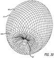
- device embodiments 10 for treatment of a patient's vasculature may include a plurality of wires, fibers, threads, tubes or other filamentary elements that form a structure that serves as a permeable shell.
- a globular shape may be formed from such filaments by connecting or securing the ends of a tubular braided structure.
- the density of a braided or woven structure may inherently increase at or near the ends where the wires or filaments 14 are brought together and decrease at or near a middle portion 30 disposed between a proximal end 32 and distal end 34 of the permeable shell 40.
- an end or any other suitable portion of a permeable shell 40 may be positioned in an opening or neck of a vascular defect such as an aneurysm for treatment.
- a braided or woven filamentary device with a permeable shell may not require the addition of a separate defect spanning structure having properties different from that of a nominal portion of the permeable shell to achieve hemostasis and occlusion of the vascular defect.
- Such a filamentary device may be fabricated by braiding, weaving or other suitable filament fabrication techniques. Such device embodiments may be shape set into a variety of three dimensional shapes such as discussed herein.
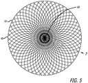
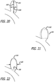
- the device 10 includes a self-expanding resilient permeable shell 40 having a proximal end 32, a distal end 34, a longitudinal axis 46 and further comprising a plurality of elongate resilient filaments 14 including large filaments 48 and small filaments 50 of at least two different transverse dimensions as shown in more detail in FIGS 5 , 7 and 18 .
- the filaments 14 have a woven structure and are secured relative to each other at proximal ends 60 and distal ends 62 thereof.
- the permeable shell 40 of the device has a radially constrained elongated state configured for delivery within a microcatheter 61, as shown in FIG. 11 , with the thin woven filaments 14 extending longitudinally from the proximal end 42 to the distal end 44 radially adjacent each other along a length of the filaments.
- the permeable shell 40 also has an expanded relaxed state with a globular and longitudinally shortened configuration relative to the radially constrained state.
- the woven filaments 14 form the self-expanding resilient permeable shell 40 in a smooth path radially expanded from a longitudinal axis 46 of the device between the proximal end 32 and distal end 34.
- the woven structure of the filaments 14 includes a plurality of openings 64 in the permeable shell 40 formed between the woven filaments.
- the largest of said openings 64 may be configured to allow blood flow through the openings only at a velocity below a thrombotic threshold velocity.
- Thrombotic threshold velocity has been defined, at least by some, as the time-average velocity at which more than 50% of a vascular graft surface is covered by thrombus when deployed within a patient's vasculature.
- a slightly different threshold may be appropriate.
- the thrombotic threshold velocity as used herein shall include the velocity at which clotting occurs within or on a device, such as device 10, deployed within a patient's vasculature such that blood flow into a vascular defect treated by the device is substantially blocked in less than about 1 hour or otherwise during the treatment procedure.
- the blockage of blood flow into the vascular defect may be indicated in some cases by minimal contrast agent entering the vascular defect after a sufficient amount of contrast agent has been injected into the patient's vasculature upstream of the implant site and visualized as it dissipates from that site.
- Such sustained blockage of flow within less than about 1 hour or during the duration of the implantation procedure may also be referred to as acute occlusion of the vascular defect.
- any blood flowing through the permeable shell may be slowed to a velocity below the thrombotic threshold velocity and thrombus will begin to form on and around the openings in the permeable shell 40.
- this process may be configured to produce acute occlusion of the vascular defect within which the device 10 is deployed.
- at least the distal end of the permeable shell 40 may have a reverse bend in an everted configuration such that the secured distal ends 62 of the filaments 14 are withdrawn axially within the nominal permeable shell structure or contour in the expanded state.
- the proximal end of the permeable shell further includes a reverse bend in an everted configuration such that the secured proximal ends 60 of the filaments 14 are withdrawn axially within the nominal permeable shell structure 40 in the expanded state.
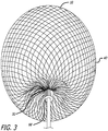
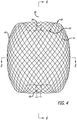
- everted may include a structure that is everted, partially everted and/or recessed with a reverse bend as shown in the device embodiment of FIGS. 3-6 .
- the ends 60 and 62 of the filaments 14 of the permeable shell or hub structure disposed around the ends may be withdrawn within or below the globular shaped periphery of the permeable shell of the device.
- the elongate resilient filaments 14 of the permeable shell 40 may be secured relative to each other at proximal ends 60 and distal ends 62 thereof by one or more methods including welding, soldering, adhesive bonding, epoxy bonding or the like.
- a distal hub 66 may also be secured to the distal ends 62 of the thin filaments 14 of the permeable shell 40 and a proximal hub 68 secured to the proximal ends 60 of the thin filaments 14 of the permeable shell 40.
- the proximal hub 68 may include a cylindrical member that extends proximally beyond the proximal ends 60 of the thin filaments so as to form a cavity 70 within a proximal portion of the proximal hub 68.
- the proximal cavity 70 may be used for holding adhesives such as epoxy, solder or any other suitable bonding agent for securing an elongate detachment tether 72 that may in turn be detachably secured to a delivery apparatus such as is shown in FIGS. 11-15 .
- the elongate resilient filaments 14 of the permeable shell 40 may have a transverse cross section that is substantially round in shape and be made from a superelastic material that may also be a shape memory metal.
- the shape memory metal of the filaments of the permeable shell 40 may be heat set in the globular configuration of the relaxed expanded state as shown in FIGS. 3-6 .
- Suitable superelastic shape memory metals may include alloys such as NiTi alloy and the like.
- the superelastic properties of such alloys may be useful in providing the resilient properties to the elongate filaments 14 so that they can be heat set in the globular form shown, fully constrained for delivery within an inner lumen of a microcatheter and then released to self expand back to substantially the original heat set shape of the globular configuration upon deployment within a patient's body.
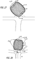
- the device10 may have an everted filamentary structure with a permeable shell 40 having a proximal end 32 and a distal end 34 in an expanded relaxed state.
- the permeable shell 40 has a substantially enclosed configuration for the embodiments shown. Some or all of the permeable shell 40 of the device 10 may be configured to substantially block or impede fluid flow or pressure into a vascular defect or otherwise isolate the vascular defect over some period of time after the device is deployed in an expanded state.
- the permeable shell 40 and device 10 generally also has a low profile, radially constrained state, as shown in FIG. 11 , with an elongated tubular or cylindrical configuration that includes the proximal end 32, the distal end 34 and a longitudinal axis 46.
- the elongate flexible filaments 14 of the permeable shell 40 may be disposed substantially parallel and in close lateral proximity to each other between the proximal end and distal end forming a substantially tubular or compressed cylindrical configuration.
- Proximal ends 60 of at least some of the filaments 14 of the permeable shell 40 may be secured to the proximal hub 68 and distal ends 62 of at least some of the filaments 14 of the permeable shell 40 are secured to the distal hub 66, with the proximal hub 68 and distal hub 66 being disposed substantially concentric to the longitudinal axis 46 as shown in FIG. 4 .
- the ends of the filaments 14 may be secured to the respective hubs 66 and 68 by any of the methods discussed above with respect to securement of the filament ends to each other, including the use of adhesives, solder, welding and the like.
- a middle portion 30 of the permeable shell 40 may have a first transverse dimension with a low profile suitable for delivery from a microcatheter as shown in FIG. 11 .
- Radial constraint on the device 10 may be applied by an inside surface of the inner lumen of a microcatheter, such as the distal end portion of the microcatheter 61 shown, or it may be applied by any other suitable mechanism that may be released in a controllable manner upon ejection of the device 10 from the distal end of the catheter.
- a proximal end or hub 68 of the device 10 is secured to a distal end of an elongate delivery apparatus 110 of a delivery system 112 disposed at the proximal hub 68 of the device 10.
- Some device embodiments 10 having a braided or woven filamentary structure may be formed using about 10 filaments to about 300 filaments 14, more specifically, about 10 filaments to about 100 filaments14, and even more specifically, about 60 filaments to about 80 filaments 14.
- Some embodiments of a permeable shell 40 may include about 70 filaments to about 300 filaments extending from the proximal end 32 to the distal end 34, more specifically, about 100 filaments to about 200 filaments extending from the proximal end 32 to the distal end 34.
- the filaments 14 may have a transverse dimension or diameter of about 20.32 ⁇ m (0.0008 inches) to about 101.6 ⁇ m (0.004 inches).
- the elongate resilient filaments 14 in some cases may have an outer transverse dimension or diameter of about 12.7 ⁇ m (0.0005 inch) to about 127 ⁇ m (0.005 inch), more specifically, about 25.4 ⁇ m (0.001 inch) to about 76.2 ⁇ m (0.003 inch), and in some cases about 10.16 ⁇ m (0.0004 inches) to about 76.2 ⁇ m (0.002 inches).
- the large filaments 48 of the permeable shell 40 may have a transverse dimension or diameter that is about 25.4 ⁇ m (0.001 inches) to about 101.6 ⁇ m (0.004 inches) and the small filaments 50 may have a transverse dimension or diameter of about 10.16 ⁇ m (0.0004 inches) to about 38.1 ⁇ m (0.0015 inches), more specifically, about 10.16 ⁇ m (0.0004 inches) to about 25.4 ⁇ m (0.001 inches).
- a difference in transverse dimension or diameter between the small filaments 50 and the large filaments 48 may be less than about 101.6 ⁇ m (0.004 inches), more specifically, less than about 88.9 ⁇ m (0.0035 inches), and even more specifically, less than about 50.8 ⁇ m (0.002 inches).
- the number of small filaments 50 of the permeable shell 40 relative to the number of large filaments 48 of the permeable shell 40 may be about 2 to 1 to about 15 to 1, more specifically, about 2 to 1 to about 12 to 1, and even more specifically, about 4 to 1 to about 8 to 1.
- the expanded relaxed state of the permeable shell 40 has an axially shortened configuration relative to the constrained state such that the proximal hub 68 is disposed closer to the distal hub 66 than in the constrained state.
- Both hubs 66 and 68 are disposed substantially concentric to the longitudinal axis 46 of the device and each filamentary element 14 forms a smooth arc between the proximal and distal hubs 66 and 68 with a reverse bend at each end.
- a longitudinal spacing between the proximal and distal hubs 66 and 68 of the permeable shell 40 in a deployed relaxed state may be about 25 percent to about 75 percent of the longitudinal spacing between the proximal and distal hubs 66 and 68 in the constrained cylindrical state, for some embodiments.
- the arc of the filaments 14 between the proximal and distal ends 32 and 34 may be configured such that a middle portion of each filament 14 has a second transverse dimension substantially greater than the first transverse dimension.
- the permeable shell 40 may have a first transverse dimension in a collapsed radially constrained state of about 0.2 mm to about 2 mm and a second transverse dimension in a relaxed expanded state of about 4 mm to about 30 mm.
- the second transverse dimension of the permeable shell 40 in an expanded state may be about 2 times to about 150 times the first transverse dimension, more specifically, about 10 times to about 25 times the first or constrained transverse dimension.
- a longitudinal spacing between the proximal end 32 and distal end 34 of the permeable shell 40 in the relaxed expanded state may be about 25% percent to about 75% percent of the spacing between the proximal end 32 and distal end 34 in the constrained cylindrical state.
- a major transverse dimension of the permeable shell 40 in a relaxed expanded state may be about 4 mm to about 30 mm, more specifically, about 9 mm to about 15 mm, and even more specifically, about 4 mm to about 8 mm.
- An arced portion of the filaments 14 of the permeable shell 40 may have a sinusoidal-like shape with a first or outer radius 88 and a second or inner radius 90 near the ends of the permeable shell 40 as shown in FIG. 6 .
- This sinusoid-like or multiple curve shape may provide a concavity in the proximal end 32 that may reduce an obstruction of flow in a parent vessel adjacent a vascular defect.
- the first radius 88 and second radius 90 of the permeable shell 40 may be between about 0.12 mm to about 3 mm.
- the distance between the proximal end 32 and distal end 34 may be less than about 60% of the overall length of the permeable shell 40 for some embodiments.
- each filament 14 may have a substantially continuous curvature. This substantially continuous curvature may provide smooth deployment and may reduce the risk of vessel perforation.
- one of the ends 32 or 34 may be retracted or everted to a greater extent than the other so as to be more longitudinally or axially conformal than the other end.
- the first radius 88 and second radius 90 of the permeable shell 40 may be between about 0.12 mm to about 3 mm for some embodiments.
- the distance between the proximal end 32 and distal end 34 may be more than about 60% of the overall length of the expanded permeable shell 40.
- the largest longitudinal distance between the inner surfaces may be about 60% to about 90% of the longitudinal length of the outer surfaces or the overall length of device 10.
- a gap between the hubs 66 and 68 at the proximal end 32 and distal end 34 may allow for the distal hub 66 to flex downward toward the proximal hub 68 when the device 10 meets resistance at the distal end and thus provides longitudinal conformance.
- the filaments 14 may be shaped such that there are no portions that are without curvature over a distance of more than about 2 mm. Thus, for some embodiments, each filament 14 may have a substantially continuous curvature. This substantially continuous curvature may provide smooth deployment and may reduce the risk of vessel perforation.
- the distal end 34 may be retracted or everted to a greater extent than the proximal end 32 such that the distal end portion of the permeable shell 40 may be more radially conformal than the proximal end portion. Conformability of a distal end portion may provide better device conformance to irregular shaped aneurysms or other vascular defects.
- a convex surface of the device may flex inward forming a concave surface to conform to curvature of a vascular site.
- FIG. 10 shows an enlarged view of the filaments 14 disposed within a proximal hub 68 of the device 10 with the filaments 14 of two different sizes constrained and tightly packed by an outer ring of the proximal hub 68.
- the tether member 72 may optionally be disposed within a middle portion of the filaments 14 or within the cavity 70 of the proximal hub 68 proximal of the proximal ends 60 of the filaments 14 as shown in FIG. 6 .
- the distal end of the tether 72 may be secured with a knot 92 formed in the distal end thereof which is mechanically captured in the cavity 70 of the proximal hub 68 formed by a proximal shoulder portion 94 of the proximal hub 68.
- the knotted distal end 92 of the tether 72 may also be secured by bonding or potting of the distal end of the tether 72 within the cavity 70 and optionally amongst the proximal ends 60 of the filaments 14 with mechanical compression, adhesive bonding, welding, soldering, brazing or the like.
- the tether embodiment 72 shown in FIG. 6 has a knotted distal end 92 potted in the cavity of the proximal hub 68 with an adhesive.
- Such a tether 72 may be a dissolvable, severable or releasable tether that may be part of a delivery apparatus 110 used to deploy the device 10 as shown in FIG. 11 and FIGS. 23-26 .
- FIG. 10 also shows the large filaments 48 and small filaments 50 disposed within and constrained by the proximal hub 68 which may be configured to secure the large and small filaments 48 and 50 in place relative to each other within the outer ring of the proximal hub 68.
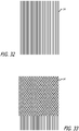
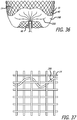
- FIGS. 7 and 8 illustrate some configuration embodiments of braided filaments 14 of a permeable shell 40 of the device 10 for treatment of a patient's vasculature.
- the braid structure in each embodiment is shown with a circular shape 100 disposed within a pore 64 of a woven or braided structure with the circular shape 100 making contact with each adjacent filament segment.
- the pore opening size may be determined at least in part by the size of the filament elements 14 of the braid, the angle overlapping filaments make relative to each other and the picks per cm/2.54 (inch) of the braid structure.
- the cells or openings 64 may have an elongated substantially diamond shape as shown in FIG.
- the pores or openings 64 of the permeable shell 40 may have a substantially more square shape toward a middle portion 30 of the device 10, as shown in FIG. 8 .
- the diamond shaped pores or openings 64 may have a length substantially greater than the width particularly near the hubs 66 and 68. In some embodiments, the ratio of diamond shaped pore or opening length to width may exceed a ratio of 3 to 1 for some cells.
- the diamond- shaped openings 64 may have lengths greater than the width thus having an aspect ratio, defined as Length/Width of greater than 1.
- the openings 64 near the hubs 66 and 68 may have substantially larger aspect ratios than those farther from the hubs as shown in FIG. 7 .
- the aspect ratio of openings 64 adjacent the hubs may be greater than about 4 to 1.
- the aspect ratio of openings 64 near the largest diameter may be between about 0.75 to 1 and about 2 to 1 for some embodiments.
- the aspect ratio of the openings 64 in the permeable shell 40 may be about 0.5 to 1 to about 2 to 1.
- the pore size defined by the largest circular shapes 100 that may be disposed within openings 64 of the braided structure of the permeable shell 40 without displacing or distorting the filaments 14 surrounding the opening 64 may range in size from about 127 ⁇ m (0.005 inches) to about 254 ⁇ m (0.01 inches), more specifically, about 152.4 ⁇ m (0.006 inches) to about 228.6 ⁇ m (0.009 inches), even more specifically, about 177.8 ⁇ m (0.007 inches) to about 203.2 ⁇ m (0.008 inches) for some embodiments.
- the openings 64 formed between adjacent filaments 14 of the permeable shell 40 of the device 10 may be configured to allow blood flow through the openings 64 only at a velocity below a thrombotic threshold velocity.
- the largest openings 64 in the permeable shell structure 40 may be configured to allow blood flow through the openings 64 only at a velocity below a thrombotic threshold velocity.
- the pore size may be less than about 0.406 mm (0.016 inches), more specifically, less than about 0.305 mm (0.012 inches) for some embodiments.
- the openings 64 formed between adjacent filaments 14 may be about 127 ⁇ m (0.005 inches) to about 1.02 mm (0.04 inches).
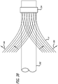
- the apparatus 110 includes an elongate core wire 114 that extends from a proximal end 116 of the apparatus 110 to a distal section 118 of the apparatus 110 as shown in FIG. 12 .
- the core wire 114 is configured to provide sufficient column strength to push a constrained device 10 for treatment of a patient's vasculature through an inner lumen 120 of the microcatheter 61 of the delivery system 112 as shown in FIG. 11 .
- the core wire 114 also has sufficient tensile strength to withdraw or proximally retract the device 10 from a position outside the microcatheter 61 and axially within the inner lumen 120 of the microcatheter 61.
- the tether 72 that extends proximally from the proximal hub 68 is secured to the distal end of the core wire 114 with a length of shrinkable tubing 122 that is disposed over a portion of the tether 72 and a distal section of the core wire 114 and shrunk over both as shown in FIG. 13 , although any other suitable means of securement may be used.
- a heater coil 124 electrically coupled to a first conductor 126 and a second conductor 128 is disposed over a distal most portion of the tether 72.
- the heater coil 124 may also be covered with a length of polymer tubing 130 disposed over the heater coil 124 distal of the heat shrink tubing 122 that serves to act as a heat shield and minimizes the leakage of heat from the heater coil 124 into the environment, such as the patient's blood stream, around the delivery apparatus 110.
- An over coil 132 that extends from a distal end 134 of the delivery apparatus 110 to a proximal section 136 of the apparatus 110 may then be disposed over the heater coil 124, core wire 114, tether 72, first conductor 126 and second conductor 128 to hold these elements together, produce a low friction outer surface and maintain a desired flexibility of the delivery apparatus 110.
- the proximal section 136 of the apparatus 110 includes the proximal terminus of the over coil 132 which is disposed distal of a first contact 138 and second contact 140 which are circumferentially disposed about the proximal section 136 of the core wire 114, insulated therefrom, and electrically coupled to the first conductor 126 and second conductor 128, respectively as shown in FIG. 15 .
- the heater coil 124 may be configured to receive electric current supplied through the first conductor 126 and second conductor 128 from an electrical energy source 142 coupled to the first contact 138 and second contact 140 at the proximal section 136 of the apparatus 110.
- the electrical current passed through the heater coil 124 heats the heater coil to a temperature above the melting point of the tether material 72 so as to melt the tether 72 and sever it upon deployment of the device 10.
- Embodiments of the delivery apparatus 110 may generally have a length greater than the overall length of a microcatheter 61 to be used for the delivery system 112. This relationship allows the delivery apparatus 110 to extend, along with the device 10 secured to the distal end thereof, from the distal port of the inner lumen 120 of the microcatheter 61 while having sufficient length extending from a proximal end 150 of the microcatheter 61, shown in FIG. 17 discussed below, to enable manipulation thereof by a physician.
- the length of the delivery apparatus 110 may be about 170 cm to about 200 cm.
- the core wire 114 may be made from any suitable high strength material such as stainless steel, NiTi alloy, or the like.
- Embodiments of the core wire 114 may have an outer diameter or transverse dimension of about 0.254 mm (0.010 inch) to about 0.381 mm (0.015 inch).
- the over coil 132 may have an outer diameter or transverse dimension of about 0.457 mm (0.018 inch) to about 0.762 mm (0.03 inch).
- the apparatus embodiment 110 shown in FIGS. 12-15 is activated by electrical energy passed through a conductor pair, a similar configuration that utilizes light energy passed through a fiber optic or any other suitable arrangement could be used to remotely heat a distal heating member or element such as the heater coil 124 to sever the distal portion of the tether 72.
- other delivery apparatus embodiments are discussed that may also be used for any of the device embodiments 10 for treatment of a patient's vasculature discussed herein.
- the delivery and positioning apparatus may include a distal rotating member that allows rotational positioning of the device.
- the delivery and positioning apparatus may include a distal rotating member which rotates an implant in-vivo without the transmission of torque along the entire length of the apparatus.
- delivery system may also rotate the implant without the transmission of torque in the intermediate portion between the proximal end and the distal rotatable end.
- the delivery and positioning apparatus may be releasably secured to any suitable portion of the device for treatment of a patient's vasculature.
- Device embodiments discussed herein may be releasable from any suitable flexible, elongate delivery apparatus or actuator such as a guidewire or guidewire-like structure.
- the release of device embodiments from such a delivery apparatus may be activated by a thermal mechanism, as discussed above, electrolytic mechanism, hydraulic mechanism, shape memory material mechanism, or any other mechanism known in the art of endovascular implant deployment.
- Embodiments for deployment and release of therapeutic devices may include connecting such a device via a releasable connection to a distal portion of a pusher or other delivery apparatus member.
- the therapeutic device 10 may be detachably mounted to the distal portion of the apparatus by a filamentary tether 72, string, thread, wire, suture, fiber, or the like, which may be referred to above as the tether.
- the tether 72 may be in the form of a monofilament, rod, ribbon, hollow tube, or the like. Some embodiments of the tether may have a diameter or maximum thickness of between about 0.05 mm and 0.2 mm.
- the tether 72 may be configured to be able to withstand a maximum tensile load of between about 0.5 kg and 5 kg.
- some known detachment devices may lack sufficient tensile strength to be used for some embodiments discussed herein. As such, it may be desirable to use small very high strength fibers for some tether embodiments having a "load at break" greater than about 15 Newtons.
- a tether made from a material known as Dyneema Purity available from Royal DSM, Heerlen, Netherlands may be used.
- the tether 72 may be severed by the input of energy such as electric current to a heating element causing release of the therapeutic device.
- the heating element may be a coil of wire with high electrical resistivity such as a platinum-tungsten alloy.
- the tether member may pass through or be positioned adjacent the heater element.
- the heater may be contained substantially within the distal portion of the delivery apparatus to provide thermal insulation to reduce the potential for thermal damage to the surrounding tissues during detachment.
- current may pass through the tether which also acts as a heating element.
- tether embodiments 72 including polymers, metals and composites thereof.
- One class of materials that may be useful for tethers includes polymers such as polyolefin, polyolefin elastomer such as polyethylene, polyester (PET), polyamide (Nylon), polyurethane, polypropylene, block copolymer such as PEBAX or Hytrel, and ethylene vinyl alcohol (EVA); or rubbery materials such as silicone, latex, and Kraton.
- the polymer may also be cross-linked with radiation to manipulate its tensile strength and melt temperature.
- Another class of materials that may be used for tether embodiment may include metals such as nickel titanium alloy (Nitinol), gold, platinum, tantalum and steel.
- LCP liquid crystal polymers
- Vectran which is produced by Kuraray Co. (Tokyo, Japan). The selection of the material may depend on the melting or softening temperature, the power used for detachment, and the body treatment site.
- the tether may be joined to the implant and/or the pusher by crimping, welding, knot tying, soldering, adhesive bonding, or other means known in the art.
- FIG. 16 shows an enlarged view in transverse cross section of a proximal hub configuration.
- the filaments 14 are disposed within a proximal hub 68 or end portion of the device 10 with the filaments 14 constrained and tightly packed by an outer ring of the proximal hub 68.
- a tether member 72 may be disposed within a middle portion of the filaments 14 or within a cavity of the proximal hub 68 proximal of the proximal ends 60 of the filaments 14.
- Such a tether 72 may be a dissolvable, severable or releasable tether that may be part of a release apparatus as discussed above used to deploy the device.
- FIG. 16 illustrates in transverse cross section an embodiment of a proximal hub 68 showing the configuration of filaments which may be tightly packed and radially constrained by an inside surface of the proximal hub 68.
- the braided or woven structure of the permeable shell 40 formed from such filaments 14 may be constructed using a large number of small filaments.
- the number of filaments14 may be greater than 125 and may also be between about 80 filaments and about 180 filaments.
- the total number of filaments 14 for some embodiments may be about 70 filaments to about 300 filaments, more specifically, about 100 filaments to about 200 filaments.
- the braided structure of the permeable shell 40 may be constructed with two or more sizes of filaments 14.
- the structure may have several larger filaments that provide structural support and several smaller filaments that provide the desired pore size and density and thus flow resistance to achieve a thrombotic threshold velocity in some cases.
- small filaments 50 of the permeable shell 40 may have a transverse dimension or diameter of about 15.24 ⁇ m (0.0006 inches) to about 50.8 ⁇ m (0.002 inches) for some embodiments and about 10.16 ⁇ m (0.0004 inches) to about 25.4 ⁇ m (0.001 inches) in other embodiments.
- the large filaments 48 may have a transverse dimension or diameter of about 38.1 ⁇ m (0.0015 inches) to about 101.6 ⁇ m (0.004 inches) in some embodiments and about 25.4 ⁇ m (0.001 inches) to about 101.6 ⁇ m (0.004 inches) in other embodiments.
- the filaments 14 may be braided in a plain weave that is one under, one over structure (shown in FIGS. 7 and 8 ) or a supplementary weave; more than one warp interlace with one or more than one weft.
- the pick count may be varied between about 25 and 200 picks per cm/2.54 (inch) (PPI).
- the permeable shell 40 or portions thereof may be porous and may be highly permeable to liquids.
- the permeable shell 40 of some embodiments discussed herein may have a water permeability greater than about 2,000 ml/min/cm 2 , in some cases greater than about 2,500 ml/min/cm 2 .
- water permeability of the permeable shell 40 or portions thereof may be between about 2,000 and 10,000 ml/min/cm 2 , more specifically, about 2,000 ml/min/cm 2 to about 15,000 ml/min/cm 2 , when measured at a pressure of 120 mmHg.
- Device embodiments and components thereof may include metals, polymers, biologic materials and composites thereof.
- Suitable metals include zirconium-based alloys, cobalt-chrome alloys, nickel-titanium alloys, platinum, tantalum, stainless steel, titanium, gold, and tungsten.
- Potentially suitable polymers include but are not limited to acrylics, silk, silicones, polyvinyl alcohol, polypropylene, polyvinyl alcohol, polyesters (e.g. polyethylene terephthalate or PET), PolyEtherEther Ketone (PEEK), polytetrafluoroethylene (PTFE), polycarbonate urethane (PCU) and polyurethane (PU).
- Device embodiments may include a material that degrades or is absorbed or eroded by the body.
- a bioresorbable e.g., breaks down and is absorbed by a cell, tissue, or other mechanism within the body
- bioabsorbable similar to bioresorbable
- a bioerodable e.g., erodes or degrades over time by contact with surrounding tissue fluids, through cellular activity or other physiological degradation mechanisms
- biodegradable e.g., degrades over time by enzymatic or hydrolytic action, or other mechanism in the body
- dissolvable material may be employed.
- Each of these terms is interpreted to be interchangeable, bioabsorbable polymer.
- bioabsorbable materials include polylactic acid (PLA), poly(alpha-hydroxy acid) such as poly-L-lactide (PLLA), poly-D-lactide (PDLA), polyglycolide (PGA), polydioxanone, polycaprolactone, polygluconate, polylactic acid-polyethylene oxide copolymers, modified cellulose, collagen, poly(hydroxybutyrate), polyanhydride, polyphosphoester, poly(amino acids), or related copolymer materials.
- PLA polylactic acid
- PLLA poly(alpha-hydroxy acid)
- PLLA poly-L-lactide
- PDLA poly-D-lactide
- PGA polyglycolide
- polydioxanone polycaprolactone
- polygluconate polylactic acid-polyethylene oxide copolymers
- modified cellulose collagen, poly(hydroxybutyrate), polyanhydride, polyphosphoester, poly(amino acids), or related copolymer materials.
- An absorbable composite fiber may be made by combining a reinforcement fiber made from a copolymer of about 18% glycolic acid and about 82% lactic acid with a matrix material consisting of a blend of the above copolymer with about 20% polycaprolactone (PCL).
- PCL polycaprolactone
- the permeable shell structure 40 may include one or more fixation elements or surfaces to facilitate fixation of the device within a blood vessel or other vascular site.
- the fixation elements may comprise hooks, barbs, protrusions, pores, microfeatures, texturing, bioadhesives or combinations thereof.
- Embodiments of the support structure may be fabricated from a tube of metal where portions are removed. The removal of material may be done by laser, electrical discharge machining (EDM), photochemical etching and traditional machining techniques.
- the support structure may be constructed with a plurality of wires, cut or etched from a sheet of a material, cut or etched from a tube or a combination thereof as in the art of vascular stent fabrication.
- Permeable shell embodiments 40 may be formed at least in part of wire, ribbon, or other filamentary elements 14. These filamentary elements 14 may have circular, elliptical, ovoid, square, rectangular, or triangular cross-sections. Permeable shell embodiments 40 may also be formed using conventional machining, laser cutting, electrical discharge machining (EDM) or photochemical machining (PCM). If made of a metal, it may be formed from either metallic tubes or sheet material.
- EDM electrical discharge machining
- PCM photochemical machining
- Device embodiments 10 discussed herein may be delivered and deployed from a delivery and positioning system 112 that includes a microcatheter 61, such as the type of microcatheter 61 that is known in the art of neurovascular navigation and therapy.
- Device embodiments for treatment of a patient's vasculature 10 may be elastically collapsed and restrained by a tube or other radial restraint, such as an inner lumen 120 of a microcatheter 61, for delivery and deployment.
- the microcatheter 61 may generally be inserted through a small incision 152 accessing a peripheral blood vessel such as the femoral artery or brachial artery.
- the microcatheter 61 may be delivered or otherwise navigated to a desired treatment site 154 from a position outside the patient's body 156 over a guidewire 159 under fluoroscopy or by other suitable guiding methods.
- the guidewire 159 may be removed during such a procedure to allow insertion of the device 10 secured to a delivery apparatus 110 of the delivery system 112 through the inner lumen 120 of a microcatheter 61 in some cases.
- FIG. 17 illustrates a schematic view of a patient 158 undergoing treatment of a vascular defect 160 as shown in FIG. 18 .
- An access sheath 162 is shown disposed within either a radial artery 164 or femoral artery 166 of the patient 158 with a delivery system 112 that includes a microcatheter 61 and delivery apparatus 110 disposed within the access sheath 162.
- the delivery system 112 is shown extending distally into the vasculature of the patient's brain adjacent a vascular defect 160 in the patient's brain.
- Access to a variety of blood vessels of a patient may be established, including arteries such as the femoral artery 166, radial artery 164, and the like in order to achieve percutaneous access to a vascular defect 160.
- the patient 158 may be prepared for surgery and the access artery is exposed via a small surgical incision 152 and access to the lumen is gained using the Seldinger technique where an introducing needle is used to place a wire over which a dilator or series of dilators dilates a vessel allowing an introducer sheath 162 to be inserted into the vessel. This would allow the device to be used percutaneously.
- a guiding catheter 168 is then used to provide a safe passageway from the entry site to a region near the target site 154 to be treated.
- a guiding catheter 168 would be chosen which would extend from the entry site 152 at the femoral artery up through the large arteries extending around the heart through the aortic arch, and downstream through one of the arteries extending from the upper side of the aorta such as the carotid artery 170.
- a guidewire 159 and neurovascular microcatheter 61 are then placed through the guiding catheter 168 and advanced through the patient's vasculature, until a distal end 151 of the microcatheter 61 is disposed adjacent or within the target vascular defect 160, such as an aneurysm.
- exemplary guidewires 159 for neurovascular use include the Synchro2® made by Boston Scientific and the Glidewire Gold Neuro® made by MicroVention Terumo. Typical guidewire sizes may include 0.355 mm (0.014 inches) and 0.457 mm (0.018 inches).
- the catheter is cleared. For example, if a guidewire 159 has been used to position the microcatheter 61, it is withdrawn from the catheter 61 and then the implant delivery apparatus 110 is advanced through the microcatheter 61.
- Delivery and deployment of device embodiments 10 discussed herein may be carried out by first compressing the device 10 to a radially constrained and longitudinally flexible state as shown in FIG. 11 .
- the device 10 may then be delivered to a desired treatment site 154 while disposed within the microcatheter 61, and then ejected or otherwise deployed from a distal end 151 of the microcatheter 61.
- the microcatheter 61 may first be navigated to a desired treatment site 154 over a guidewire 159 or by other suitable navigation techniques.
- the distal end of the microcatheter 61 may be positioned such that a distal port of the microcatheter 61 is directed towards or disposed within a vascular defect 160 to be treated and the guidewire 159 withdrawn.
- the device 10 secured to a suitable delivery apparatus 110 may then be radially constrained, inserted into a proximal portion of the inner lumen 120 of the microcatheter 61 and distally advanced to the vascular defect 160 through the inner lumen
- the device 10 may then allowed to assume an expanded relaxed or partially relaxed state with the permeable shell 40 of the device spanning or partially spanning a portion of the vascular defect 160 or the entire vascular defect 160.
- the device 10 may also be activated by the application of an energy source to assume an expanded deployed configuration once ejected from the distal section of the microcatheter 61 for some embodiments. Once the device 10 is deployed at a desired treatment site 154, the microcatheter 61 may then be withdrawn.
- Some embodiments of devices for the treatment of a patient's vasculature 10 discussed herein may be directed to the treatment of specific types of defects of a patient's vasculature.
- an aneurysm 160 commonly referred to as a terminal aneurysm is shown in section. Terminal aneurysms occur typically at bifurcations in a patient's vasculature where blood flow, indicated by the arrows 172, from a supply vessel splits into two or more branch vessels directed away from each other.
- the main flow of blood from the supply vessel 174 such as a basilar artery, sometimes impinges on the vessel where the vessel diverges and where the aneurysm sack forms.
- Terminal aneurysms may have a well defined neck structure where the profile of the aneurysm 160 narrows adjacent the nominal vessel profile, but other terminal aneurysm embodiments may have a less defined neck structure or no neck structure.
- FIG. 19 illustrates a typical berry type aneurysm 160 in section where a portion of a wall of a nominal vessel section weakens and expands into a sack like structure ballooning away from the nominal vessel surface and profile.
- Some berry type aneurysms may have a well defined neck structure as shown in FIG. 19 , but others may have a less defined neck structure or none at all.
- FIG. 19 illustrates a typical berry type aneurysm 160 in section where a portion of a wall of a nominal vessel section weakens and expands into a sack like structure ballooning away from the nominal vessel surface and profile.
- Some berry type aneurysms may have a well defined neck structure as shown in FIG. 19 , but others may have a less defined
- FIG. 19 also shows some optional procedures wherein a stent 173 or other type of support has been deployed in the parent vessel 174 adjacent the aneurysm. Also, shown is embolic material 176 being deposited into the aneurysm 160 through a microcatheter 61. Either or both of the stent 173 and embolic material 176 may be so deployed either before or after the deployment of a device for treatment of a patient's vasculature 10.
- Some embodiments of treatment may include estimating a volume of a vascular site or defect 160 to be treated and selecting a device 10 with a volume that is substantially the same volume or slightly over-sized relative to the volume of the vascular site or defect 160.
- the volume of the vascular defect 160 to be occluded may be determined using three-dimensional angiography or other similar imaging techniques along with software which calculates the volume of a selected region.
- the amount of over-sizing may be between about 2% and 15% of the measured volume.
- Such a method embodiment may also include implanting or deploying the device 10 so that the vascular defect 160 is substantially filled volumetrically by a combination of device and blood contained therein.
- the device 10 may be configured to be sufficiently conformal to adapt to irregular shaped vascular defects 160 so that at least about 75%, in some cases about 80%, of the vascular defect volume is occluded by a combination of device 10 and blood contained therein.
- FIGS. 20-22 illustrate a schematic representation of how a device 10 may be chosen for a proper fit after deployment that is initially oversized in a transverse dimension by at least about 10% of the largest transverse dimension of the vascular defect 160 and sometimes up to about 100% of the largest transverse dimension.
- the device 10 may be oversized a small amount (e.g. less than about 1.5 mm) in relation to measured dimensions for the width, height or neck diameter of the vascular defect 160.
- a vascular defect 160 in the form of a cerebral aneurysm is shown with horizontal arrows 180 and vertical arrows 182 indicating the approximate largest interior dimensions of the defect 160.
- Arrow 180 extending horizontally indicates the largest transverse dimension of the defect 160.
- a dashed outline 184 of a device for treatment of the vascular defect 10 is shown superimposed over the vascular defect 160 of FIG. 20 illustrating how a device 10 that has been chosen to be approximately 20% oversized in a transverse dimension would look in its unconstrained, relaxed state.
- FIG 22 illustrates how the device 10 which is indicated by the dashed line 184 of FIG.
- the device 10 might conform to the interior surface of the vascular defect 160 after deployment whereby the nominal transverse dimension of the device 10 in a relaxed unconstrained state has now been slightly constrained by the inward radial force 185 exerted by the vascular defect 160 on the device 10.
- the device 10 has assumed a slightly elongated shape in the axial or longitudinal axis of the device 10 so as to elongate and better fill the interior volume of the defect 160 as indicated by the downward arrow 186 in FIG. 22 .
- the delivery and deployment process may then proceed.
- the properties of the device embodiments 10 and delivery system embodiments 112 discussed herein generally allow for retraction of a device 10 after initial deployment into a defect 160, but before detachment of the device 10. Therefore, it may also be possible and desirable to withdraw or retrieve an initially deployed device 10 after the fit within the defect 160 has been evaluated in favor of a differently sized device 10.
- An example of a terminal aneurysm 160 is shown in FIG. 23 in section.
- the tip 151 of a catheter, such as a microcatheter 61 may be advanced into or adjacent the vascular site or defect 160 (e.g. aneurysm) as shown in FIG. 24 .
- an embolic coil or other vaso-occlusive device or material 176 may optionally be placed within the aneurysm 160 to provide a framework for receiving the device 10.
- a stent 173 may be placed within a parent vessel 174 of some aneurysms substantially crossing the aneurysm neck prior to or during delivery of devices for treatment of a patient's vasculature discussed herein (also as shown for example in FIG. 19 ).
- An example of a suitable microcatheter 61 having an inner lumen diameter of about 0.508 mm (0.020 inches) to about 0.559 mm (0.022 inches) is the Rapid Transit® manufactured by Cordis Corporation.
- microcatheters 61 may include microcatheters having an inner lumen diameter of about 0.660 mm (0.026 inch) to about 0.711 mm (0.028 inch), such as the Rebar® by Ev3 Company, the Renegade Hi-Flow® by Boston Scientific Corporation, and the Mass Transit® by Cordis Corporation.
- Suitable microcatheters having an inner lumen diameter of about 0.787 mm (0.031 inch) to about 0.838 mm (0.033 inch) may include the Marksmen® by Chestnut Medical Technologies, Inc. and the Vasco 28® by Bait Extrusion.
- a suitable microcatheter 61 having an inner lumen diameter of about 0.991 mm (0.039 inch) to about 1.041 mm (0.041 inch) includes the Vasco 35 by Bait Extrusion. These microcatheters 61 are listed as exemplary embodiments only, other suitable microcatheters may also be used with any of the embodiments discussed herein.
- Detachment of the device 10 from the delivery apparatus 110 may be controlled by a control switch 188 disposed at a proximal end of the delivery system 112, which may also be coupled to an energy source 142, which severs the tether 72 that secures the proximal hub 68 of the device 10 to the delivery apparatus 110.
- a control switch 188 disposed at a proximal end of the delivery system 112, which may also be coupled to an energy source 142, which severs the tether 72 that secures the proximal hub 68 of the device 10 to the delivery apparatus 110.
- the filaments 14 of the permeable shell 40 may take on an elongated, non-everted configuration substantially parallel to each other and a longitudinal axis of the catheter 61.
- the distal ends 62 of the filaments 14 may then axially contract towards each other so as to assume the globular everted configuration within the vascular defect 160 as shown in FIG. 25 .
- the device 10 may be inserted through the microcatheter 61 such that the catheter lumen 120 restrains radial expansion of the device 10 during delivery. Once the distal tip or deployment port of the delivery system 112 is positioned in a desirable location adjacent or within a vascular defect 160, the device 10 may be deployed out the distal end of the catheter 61 thus allowing the device to begin to radially expand as shown in FIG. 25 . As the device 10 emerges from the distal end of the delivery system 112, the device 10 expands to an expanded state within the vascular defect 160, but may be at least partially constrained by an interior surface of the vascular defect 160.
- radial expansion of the device 10 may serve to secure the device 10 within the vascular defect 160 and also deploy the permeable shell 40 across at least a portion of an opening 190 (e.g. aneurysm neck) so as to at least partially isolate the vascular defect 160 from flow, pressure or both of the patient's vasculature adjacent the vascular defect 160 as shown in FIG. 26 .
- the conformability of the device 10, particularly in the neck region 190 may provide for improved sealing.
- the permeable shell 40 may substantially slow flow of fluids and impede flow into the vascular site and thus reduce pressure within the vascular defect 160.
- the device 10 may be implanted substantially within the vascular defect 160, however, in some embodiments, a portion of the device 10 may extend into the defect opening or neck 190 or into branch vessels.
- One exemplary case study that has been conducted includes a procedure performed on a female canine where an aneurysm was surgically created in the subject canine.
- the target aneurysm prior to treatment had a maximum transverse dimension of about 8 mm, a length of about 10 mm and a neck measurement of about 5.6 mm.
- the device 10 deployed included a permeable shell 40 formed of 144 resilient filaments having a transverse diameter of about 38.1 ⁇ m (0.0015 inches) braided into a globular structure having a transverse dimension of about 10 mm and a longitudinal length of about 7 mm in a relaxed expanded state.
- the maximum size 100 of the pores 64 of the expanded deployed permeable shell 40 was about 0.330 mm (0.013 inches).
- the device was delivered to the target aneurysm using a 5 Fr. Guider Softip XF guide catheter made by Boston Scientific.
- Another exemplary case study conducted involved treatment of a surgically created aneurysm in a New Zealand White Rabbit.
- the target aneurysm prior to treatment had a maximum transverse dimension of about 3.6 mm, length of about 5.8 mm and a neck measurement of about 3.4 mm.
- the device 10 deployed included a permeable shell formed of 144 resilient filaments having a transverse diameter of about 25.4 ⁇ m (0.001 inches) braided into a globular structure having a transverse dimension of about 4 mm and a length of about 5 mm in a relaxed expanded state.
- the pore size 100 of the portion of the braided mesh of the expanded deployed permeable shell 40 that was configured to span the neck of the vascular defect was about 127 ⁇ m (0.005 inches).
- the device was delivered to the surgically created aneurysm with a 5 Fr. Envoy STR guide catheter manufactured by Cordis Neurovascular.
- a Renegade Hi-Flo microcatheter manufactured by Boston Scientific having an inner lumen diameter of about 0.686 mm (0.027 inches) was then inserted through the guide catheter and served as a conduit for delivery of the device 10 secured to a distal end of a delivery apparatus.
- the vascular defect 160 achieved at least partial occlusion at 5 minutes from implantation.
- no further data was taken during the procedure. Complete occlusion was observed for the device when examined at 3 weeks from the procedure.
- the device 10 may be manipulated by the user to position the device 10 within the vascular site or defect 160 during or after deployment but prior to detachment.
- the device 10 may be rotated in order to achieve a desired position of the device 10 and, more specifically, a desired position of the permeable shell 40, prior to or during deployment of the device 10.
- the device 10 may be rotated about a longitudinal axis of the delivery system 112 with or without the transmission or manifestation of torque being exhibited along a middle portion of a delivery catheter being used for the delivery. It may be desirable in some circumstances to determine whether acute occlusion of the vascular defect 160 has occurred prior to detachment of the device 10 from the delivery apparatus 110 of the delivery system 112.
- Some method embodiments include deploying the device 10 at a confluence of three vessels of the patient's vasculature that form a bifurcation such that the permeable shell 40 of the device 10 substantially covers the neck of a terminal aneurysm. Once the physician is satisfied with the deployment, size and position of the device 10, the device 10 may then be detached by actuation of the control switch 188 by the methods described above and shown in FIG. 26 . Thereafter, the device 10 is in an implanted state within the vascular defect 160 to effect treatment thereof.
- FIG. 27 illustrates another configuration of a deployed and implanted device in a patients vascular defect 160. While the implantation configuration shown in FIG. 26 indicates a configuration whereby the longitudinal axis 46 of the device 10 is substantially aligned with a longitudinal axis of the defect 160, other suitable and clinically effective implantation embodiments may be used. For example, FIG. 27 shows an implantation embodiment whereby the longitudinal axis 46 of the implanted device 10 is canted at an angle of about 10 degrees to about 90 degrees relative to a longitudinal axis of the target vascular defect 160. Such an alternative implantation configuration may also be useful in achieving a desired clinical outcome with acute occlusion of the vascular defect 160 in some cases and restoration of normal blood flow adjacent the treated vascular defect. FIG.
- the aneurysm 160 shown has at least two distinct lobes 192 extending from the main aneurysm cavity.
- the two lobes 192 shown are unfilled by the deployed vascular device 10, yet the lobes 192 are still isolated from the parent vessel of the patient's body due to the occlusion of the aneurysm neck portion 190.
- Markers, such as radiopaque markers, on the device 10 or delivery system 112 may be used in conjunction with external imaging equipment (e.g. x-ray) to facilitate positioning of the device or delivery system during deployment.
- external imaging equipment e.g. x-ray
- the device 10 may be detached by the user.
- the detachment of the device 10 from the delivery apparatus 110 of the delivery system 112 may be affected by the delivery of energy (e.g. heat, radiofrequency, ultrasound, vibrational, or laser) to a junction or release mechanism between the device 10 and the delivery apparatus 110.
- the delivery system 112 may be withdrawn from the patient's vasculature or patient's body 158.
- a stent 173 may be place within the parent vessel substantially crossing the aneurysm neck 190 after delivery of the device 10 as shown in FIG. 19 for illustration.
- a biologically active agent or a passive therapeutic agent may be released from a responsive material component of the device 10.
- the agent release may be affected by one or more of the body's environmental parameters or energy may be delivered (from an internal or external source) to the device 10. Hemostasis may occur within the vascular defect 160 as a result of the isolation of the vascular defect 160, ultimately leading to clotting and substantial occlusion of the vascular defect 160 by a combination of thrombotic material and the device 10.
- thrombosis within the vascular defect 160 may be facilitated by agents released from the device 10 and/or drugs or other therapeutic agents delivered to the patient.
- the attachment of platelets to the permeable shell 40 may be inhibited and the formation of clot within an interior space of the vascular defect 160, device, or both promoted or otherwise facilitated with a suitable choice of thrombogenic coatings, antithrombogenic coatings or any other suitable coatings (not shown) which may be disposed on any portion of the device 10 for some embodiments, including an outer surface of the filaments 14 or the hubs 66 and 68.
- a coating or coatings may be applied to any suitable portion of the permeable shell 40.
- Energy forms may also be applied through the delivery apparatus 110 and/or a separate catheter to facilitate fixation and/or healing of the device 10 adjacent the vascular defect 160 for some embodiments.
- One or more embolic devices or embolic material 176 may also optionally be delivered into the vascular defect 160 adjacent permeable shell portion that spans the neck or opening 190 of the vascular defect 160 after the device 10 has been deployed.
- a stent or stent-like support device 173 may be implanted or deployed in a parent vessel adjacent the defect 160 such that it spans across the vascular defect 160 prior to or after deployment of the vascular defect treatment device 10.
- the device 10 may have sufficient radial compliance so as to be readily retrievable or retractable into a typical microcatheter 61.
- the proximal portion of the device 10, or the device as a whole for some embodiments, may be engineered or modified by the use of reduced diameter filaments, tapered filaments, or filaments oriented for radial flexure so that the device 10 is retractable into a tube that has an internal diameter that is less than about 0.7 mm, using a retraction force less than about 2.7 Newtons (0.6 Ibf) force.
- the force for retrieving the device 10 into a microcatheter 61 may be between about 0.8 Newtons (0.18 Ibf) and about 2.25 Newtons (0.5 Ibf).
- Engagement of the permeable shell 40 with tissue of an inner surface of a vascular defect 160 when in an expanded relaxed state, may be achieved by the exertion of an outward radial force against tissue of the inside surface of the cavity of the patient's vascular defect 160 as shown in FIG. 29 .
- a similar outward radial force may also be applied by a proximal end portion and permeable shell 40 of the device 10 so as to engage the permeable shell 40 with an inside surface or adjacent tissue of the vascular defect 160.
- Such forces may be exerted in some embodiments wherein the nominal outer transverse dimension or diameter of the permeable shell 40 in the relaxed unconstrained state is larger than the nominal inner transverse dimension of the vascular defect 160 within which the device 10 is being deployed, i.e., oversizing as discussed above.
- the elastic resiliency of the permeable shell 40 and filaments 14 thereof may be achieved by an appropriate selection of materials, such as superelastic alloys, including nickel titanium alloys, or any other suitable material for some embodiments.
- the conformability of a proximal portion of the permeable shell 40 of the device 10 may be such that it will readily ovalize to adapt to the shape and size of an aneurysm neck 190, as shown in FIGS. 20-22 , thus providing a good seal and barrier to flow around the device.
- the device 10 may achieve a good seal, substantially preventing flow around the device without the need for fixation members that protrude into the parent vessel.
- Some implanted device embodiments 10 have the ends of the filaments 14 of the permeable shell 40 disposed even with or just within a plane formed by the apices of the filaments disposed adjacent to the ends.
- Some embodiments of the device 10 may also include a sealing member disposed within or about a perimeter zone 198 or other suitable portion of the permeable shell 40 and be configured to facilitate the disruption of flow, a fibrotic tissue response, or physically form a seal between the permeable shell 40 and a surface of the patient's vasculature.
- the sealing member may comprise coatings, fibers or surface treatments as described herein.
- the sealing member may be in a part or all of an area of the periphery of the device adjacent where the device contacts the wall of the aneurysm near the aneurysm neck (sealing zone 198) as shown in FIGS. 29 and 30 .
- the zone may extend from about the apex of the outer proximal end radius 88 for a distance up to about 20% of the height of the expanded device 10.
- the sealing zone 198 may include between about 5% and 30% of the device 10 surface area. Since the flow of blood into an aneurysm 160 generally favors one side of the opening, the sealing member may be incorporated in or attached to the permeable shell 40 structure throughout the peripheral area (sealing zone 198) shown in Figure 30 .
- Some embodiments of the sealing member may include a swellable polymer.
- the sealing member may include or bioactive material or agent such as a biologic material or biodegradable, bioresorbable or other bioactive polymer or copolymers thereof.
- any embodiment of devices for treatment of a patient's vasculature 10, delivery system 112 for such devices 10 or both discussed herein may be adapted to deliver energy to the device for treatment of a patient's vasculature or to tissue surrounding the device 10 at the implant site for the purpose of facilitating fixation of a device 10, healing of tissue adjacent the device or both.
- energy may be delivered through a delivery system 112 to the device 10 for treatment of a patient's vasculature such that the device 10 is heated.
- energy may be delivered via a separate elongate instrument (e.g. catheter, not shown) to the device 10 for treatment of a patient's vasculature and/or surrounding tissue at the site of the implant 154.
- energy embodiments that may be delivered include but are not limited to light energy, thermal or vibration energy, electromagnetic energy, radio frequency energy and ultrasonic energy.
- energy delivered to the device 10 may trigger the release of chemical or biologic agents to promote fixation of a device for treatment of a patient's vasculature 10 to a patient's tissue, healing of tissue disposed adjacent such a device 10 or both.
- the permeable shell 40 of some device embodiments 10 may also be configured to react to the delivery of energy to effect a change in the mechanical or structural characteristics, deliver drugs or other bioactive agents or transfer heat to the surrounding tissue.
- some device embodiments 10 may be made softer or more rigid from the use of materials that change properties when exposed to electromagnetic energy (e.g. heat, light, or radio frequency energy).
- the permeable shell 40 may include a polymer that reacts in response to physiologic fluids by expanding.
- An exemplary material is described by Cox in U.S. Patent Application No. 2004/0186562, filed January 22, 2004 , titled "Aneurysm Treatment Device and Method of Use".
- FIG. 31 illustrates a flattened analog representation of a non-braided filament structure for reference.
- the woven structure may include a portion where the weave or braid of the filaments 14 is interrupted as shown in a flat pattern analog pattern in FIG. 35 .
- the filaments 14 may be substantially parallel to each other.
- the interrupted area may provide a region with different mechanical characteristics such as radial stiffness and/or compliance.
- the interrupted region may allow for the addition of non-structural fibers or sealing members 200 as described herein or other elements to facilitate fixation, healing, fibrosis or thrombosis.
- the interrupted region may be within, part of or adjacent to the sealing member zone 198 as shown in FIGS. 29 and 30 .
- the interrupted region may be less than about 50% of the surface area and may be between about 5% and 25% of the surface area.
- filamentary or fibrous members that are substantially non-structural may be attached or interwoven into the structural filaments of a portion of the permeable shell to increase a resistance to the flow of blood through the permeable shell structure 40.
- a plurality of fibers 200 may be attached on the inner surface of the permeable shell 40 near the proximal hub 68 as shown in FIG. 36 .
- the fibrous members 200 may be the fibers that form the detachment system tether for some embodiments.
- one or more fibers 200 may be interwoven into the permeable shell filaments 14 as shown in Figure 37 .
- the non-structural fibers 200 which may be microfibers or any other suitable fibers, may be polymeric.
- the non-structural fibers 200 may include, but not limited to, any of the fibers or microfibers discussed or incorporated herein.
- device embodiments for treatment of a patient's vasculature 10 may generally be fabricated by braiding a substantially tubular braided structure with filamentary elements 14, forming the braided tubular structure into a desired shape, and heat setting the braided formed filaments into the desired shape. Once so formed, the ends of the elongate resilient filaments 14 may then be secured together relative to each other by any of the exemplary methods discussed above and proximal and distal hubs 66 and 68 added.
- FIG. 38 An embodiment of a process for braiding a tubular braided structure by a manual process is shown in FIG. 38 .
- a plurality of elongate resilient filaments 14 are secured at one end of an elongate cylindrical braiding mandrel 202 by a constraining band 204.
- the band 204 may include any suitable structure that secured the ends of the filaments 14 relative to the mandrel 202 such as a band of adhesive tape, an elastic band, an annular clamp or the like.
- the loose ends of the filaments 14 opposite the secured ends are being manipulated in a braided or woven pattern as indicated by the arrows 206 to achieve a one over-one under braid pattern for generation of a braided tubular member 208.
- a braided or woven pattern As discussed above, although a one over-one under simple braid pattern is shown and discussed, other braid or weave patterns may also be used. One such example of another braid configuration may include a two over-one under pattern.
- FIG. 39 illustrates the braided tubular member 208 taking shape and lengthening as the braiding process continues as indicated by the arrows 206 in FIG. 39 . Once the braided tubular member 208 achieves sufficient length, it may be removed from the braiding mandrel 202 and positioned within a shaping fixture such as the shaping fixture embodiments shown in FIGS. 40 and 41 .
- FIG. 40 shows the tubular braided member 208 disposed over an internal rod mandrel 210 that extends through central lumens of an internal ball mandrel 212 and a pair of opposed recessed end forming mandrels 214.
- the tubular braided member 208 is also disposed over an outer surface of the internal ball mandrel 212 and within an inner lumen of each of the end forming mandrels 214.
- the end forming mandrels 214 are configured to be pushed against and into the recessed ends 216 of the internal ball mandrel 212 such that the inside surface of the braided tubular member 208 is held against the outer contour of the internal ball mandrel 212 and fixed in place.
- This entire fixture 220 with the inside surface of the braided tubular structure 208 held against the outside surface of the internal ball mandrel 212 may then be subjected to an appropriate heat treatment such that the resilient filaments 14 of the braided tubular member 208 assume or are otherwise shape-set to the outer contour of the central ball mandrel 212.
- the filamentary elements 14 of the permeable shell 40 may be held by a fixture configured to hold the permeable shell 40 in a desired shape and heated to about 475-525 degrees C for about 5-10 minutes to shape-set the structure.
- the central ball mandrel 212 may be configured to have any desired shape so as to produce a shape set tubular braided member 208 that forms a permeable shell 40 having a desired shape and size such as the globular configuration of the device 10 of FIGS. 3-6 above, or any other suitable configuration.
- the central ball mandrel 212 may also be a globular-shaped ball with recesses in opposing sides for the hubs 66 and 68 that is placed inside the tubular braid 208.
- a mold or molds that have one or more pieces that are assembled to form a cavity with the desired device shape may also be used in conjunction with or in place of the end forming mandrels 214.
- the permeable shell 40 may be formed as discussed above by securing proximal ends 60 and distal ends 62 of elongate filamentary elements 14, or to respective proximal and distal hubs 66 and 68.
- FIG. 41 shows another embodiment of a fixture for shape setting the permeable shell 40 of a device for treatment of a patient's vasculature.
- the fixture embodiment 230 of FIG. 41 may be used in essentially the same manner as the fixture embodiment 220 of FIG. 40 , except that instead of a central ball mandrel 212, an internal tube mandrel 232 is used in conjunction with an external tube restraint 234 in order to hold the shape of the braided tubular member 208 during the heat setting process. More specifically, the tubular braided member 208 is disposed over an internal rod mandrel 210 that extends through central lumens of the internal tube mandrel 232 and a pair of opposed recessed end forming mandrels 214. The tubular braided member 208 is also disposed over an outer surface of the internal tube mandrel 232 and within an inner lumen of each of the end forming mandrels 214.
- the end forming mandrels 214 are configured to be pushed against and into recessed ends 238 of the internal tube mandrel 232 such that the inside surface of the braided tubular member 208 is held against the outer contour of the internal tube mandrel 232 and fixed in place at the ends of the tube mandrel 232.
- the braided tubular member 208 radially expands outwardly until it touches and is radially constrained by an inside surface of an external tube mandrel 234.
- the combination of axial restraint and securement of the braided tubular member 208 at the ends of the internal tube mandrel 232 in conjunction with the inward radial restraint on an outside surface of the braided tubular member 208 disposed between the proximal and distal ends thereof, may be configured to produce a desired globular configuration suitable for the permeable shell 40 of the device 10.
- this entire fixture 230 with the inside surface of the ends of the braided tubular structure 208 held against the outside surface of the ends of the internal tube mandrel 232 and an outside surface of the braided tubular member 208 radially constrained by an inside surface 233 of the external tube member 234, may then be subjected to an appropriate heat treatment.
- the heat treatment may be configured such that the resilient filaments 14 of the braided tubular member 208 assume or are otherwise shape-set to the globular contour of the filaments 14 generated by the fixture 230.
- the filamentary elements 14 of the permeable shell 40 may be held by a fixture configured to hold the braided tubular member 208 in a desired shape and heated to about 475-525 degrees C for about 5-10 minutes to shape-set the structure.
- the internal tube mandrel 232 and inside surface 233 of the external tube member 234 may be so configured to have any desired shape so as to produce a shape set tubular braided member 208 that forms a permeable shell 40 having a desired shape and size such as the globular configuration of the device of FIGS. 3-6 above, or any other suitable configuration.
- material may be attached to filaments 14 of the permeable shell 40 of a device 10 such that it substantially reduces the size of the fenestrations, cells or pores 64 between filaments 14 and thus reduces the porosity in that area.
- coating embodiments may be disposed on portions of the filaments 14 to create small fenestrations or cells and thus higher density of the permeable shell 40.
- Active materials such as a responsive hydrogel may be attached or otherwise incorporated into permeable shell 40 of some embodiments such that it swells upon contact with liquids over time to reduce the porosity of the permeable shell 40.
- Device embodiments 10 discussed herein may be coated with various polymers to enhance it performance, fixation and/or biocompatibility.
- device embodiments 10 may be made of various biomaterials known in the art of implant devices including but not limited to polymers, metals, biological materials and composites thereof.
- Device embodiments discussed herein may include cells and/or other biologic material to promote healing.
- Device embodiments discussed herein may also be constructed to provide the elution or delivery of one or more beneficial drugs, other bioactive substances or both into the blood or the surrounding tissue.
- Permeable shell embodiments 40 of devices for treatment of a patient's vasculature 10 may include multiple layers.
- a first or outer layer may be constructed from a material with low bioactivity and hemocompatibility so as to minimize platelet aggregation or attachment and thus the propensity to form clot and thrombus.
- an outer layer may be coated or incorporate an antithrombogenic agent such as heparin or other antithrombogenic agents described herein or known in the art.
- One or more inner layers disposed towards the vascular defect in a deployed state relative to the first layer may be constructed of materials that have greater bioactivity and/or promote clotting and thus enhance the formation of an occlusive mass of clot and device within the vascular defect.
- Some materials that have been shown to have bioactivity and/or promote clotting include silk, polylactic acid (PLA), polyglycolic acid (PGA), collagen, alginate, fibrin, fibrinogen, fibronectin, Methylcellulose, gelatin, Small Intestinal Submucosa (SIS), poly-N-acetylglucosamine and copolymers or composites thereof.
- PLA polylactic acid
- PGA polyglycolic acid
- collagen alginate
- fibrin fibrinogen
- fibronectin Methylcellulose
- gelatin Small Intestinal Submucosa
- SIS Small Intestinal Submucosa
- poly-N-acetylglucosamine copolymers or composites thereof.
- Bioactive agents suitable for use in the embodiments discussed herein may include those having a specific action within the body as well as those having nonspecific actions.
- Specific action agents are typically proteinaceous, including thrombogenic types and/or forms of collagen, thrombin and fibrogen (each of which may provide an optimal combination of activity and cost), as well as elastin and von Willebrand factor (which may tend to be less active and/or expensive agents), and active portions and domains of each of these agents.
- Thrombogenic proteins typically act by means of a specific interaction with either platelets or enzymes that participate in a cascade of events leading eventually to clot formation.
- Agents having nonspecific thrombogenic action are generally positively charged molecules, e.g., polymeric molecules such as chitosan, polylysine, poly(ethylenimine) or acrylics polymerized from acrylimide or methacrylamide which incorporate positively-charged groups in the form of primary, secondary, or tertiary amines or quarternary salts, or non-polymeric agents such as (tridodecylmethylammonium chloride).
- Positively charged hemostatic agents promote clot formation by a non-specific mechanism, which includes the physical adsorption of platelets via ionic interactions between the negative charges on the surfaces of the platelets and the positive charges of the agents themselves.
- Device embodiments 10 herein may include a surface treatment or coating on a portion, side or all surfaces that promotes or inhibits thrombosis, clotting, healing or other embolization performance measure.
- the surface treatment or coating may be a synthetic, biologic or combination thereof.
- at least a portion of an inner surface of the permeable shell 40 may have a surface treatment or coating made of a biodegradable or bioresorbable material such as a polylactide, polyglycolide or a copolymer thereof.
- Another surface treatment or coating material which may enhance the embolization performance of a device includes a polysachharide such as an alginate based material.
- Some coating embodiments may include extracellular matrix proteins such as ECM proteins.
- coatings may be applied with a thickness that is less than about 25% of a transverse dimension of the filaments 14.
- Antiplatelet agents may include aspirin, glycoprotein IIb/IIIa receptor inhibitors (including, abciximab, eptifibatide, tirofiban, lamifiban, fradafiban, cromafiban, toxifiban, XV454, lefradafiban, klerval, lotrafiban, orbofiban, and xemilofiban), dipyridamole, apo-dipyridamole, persantine, prostacyclin, ticlopidine, clopidogrel, cromafiban, cilostazol, and nitric oxide.
- glycoprotein IIb/IIIa receptor inhibitors including, abciximab, eptifibatide, tirofiban, lamifiban, fradafiban, cromafiban, toxifiban, XV454, lefradafiban, klerval, lotrafiban, orbofi
- device embodiments may include a polymer that releases nitric oxide.
- Device embodiments 10 may also deliver or include an anticoagulant such as heparin, low molecular weight heparin, hirudin, warfarin, bivalirudin, hirudin, argatroban, forskolin, ximelagatran, vapiprost, prostacyclin and prostacyclin analogues, dextran, synthetic antithrombin, Vasoflux, argatroban, efegatran, tick anticoagulant peptide, Ppack, HMG-CoA reductase inhibitors, and thromboxane A2 receptor inhibitors.
- an anticoagulant such as heparin, low molecular weight heparin, hirudin, warfarin, bivalirudin, hirudin, argatroban, forskolin, ximelagatran, vapiprost, prostacyclin and prostacyclin analogues, dextran,
- the permeable shell 40 of a device 10 may be coated with a composition that may include nanoscale structured materials or precursors thereof (e.g., self-assembling peptides).
- the peptides may have with alternating hydrophilic and hydrophobic monomers that allow them to self-assemble under physiological conditions.
- the composition may comprise a sequence of amino acid residues.
- the permeable shell may include a thin metallic film material.
- the thin film metal may be fabricated by sputter deposition and may be formed in multiple layers.
- the thin film may be a nickel-titanium alloy also known as nitinol.
Applications Claiming Priority (2)
| Application Number | Priority Date | Filing Date | Title |
|---|---|---|---|
| US5012408P | 2008-05-02 | 2008-05-02 | |
| PCT/US2009/042592 WO2009135166A2 (en) | 2008-05-02 | 2009-05-01 | Filamentary devices for treatment of vascular defects |
Publications (3)
| Publication Number | Publication Date |
|---|---|
| EP2279023A2 EP2279023A2 (en) | 2011-02-02 |
| EP2279023A4 EP2279023A4 (en) | 2014-11-26 |
| EP2279023B1 true EP2279023B1 (en) | 2020-12-02 |
Family
ID=41255880
Family Applications (1)
| Application Number | Title | Priority Date | Filing Date |
|---|---|---|---|
| EP09739968.7A Active EP2279023B1 (en) | 2008-05-02 | 2009-05-01 | Filamentary devices for treatment of vascular defects |
Country Status (8)
| Country | Link |
|---|---|
| US (6) | US9597087B2 (ja) |
| EP (1) | EP2279023B1 (ja) |
| JP (7) | JP2011519632A (ja) |
| CN (2) | CN102119040A (ja) |
| AU (2) | AU2009242528B2 (ja) |
| BR (1) | BRPI0911923B8 (ja) |
| CA (2) | CA2722672C (ja) |
| WO (1) | WO2009135166A2 (ja) |
Families Citing this family (193)
| Publication number | Priority date | Publication date | Assignee | Title |
|---|---|---|---|---|
| US7569066B2 (en) | 1997-07-10 | 2009-08-04 | Boston Scientific Scimed, Inc. | Methods and devices for the treatment of aneurysms |
| DE10233085B4 (de) | 2002-07-19 | 2014-02-20 | Dendron Gmbh | Stent mit Führungsdraht |
| US8425549B2 (en) | 2002-07-23 | 2013-04-23 | Reverse Medical Corporation | Systems and methods for removing obstructive matter from body lumens and treating vascular defects |
| US20110208233A1 (en) * | 2004-01-22 | 2011-08-25 | Mcguckin Jr James F | Device for preventing clot migration from left atrial appendage |
| US8267985B2 (en) | 2005-05-25 | 2012-09-18 | Tyco Healthcare Group Lp | System and method for delivering and deploying an occluding device within a vessel |
| US20060155323A1 (en) * | 2005-01-07 | 2006-07-13 | Porter Stephen C | Intra-aneurysm devices |
| US8273101B2 (en) | 2005-05-25 | 2012-09-25 | Tyco Healthcare Group Lp | System and method for delivering and deploying an occluding device within a vessel |
| CN101180006B (zh) | 2005-05-25 | 2010-09-22 | 切斯纳特医药技术公司 | 用于在血管内输送和展开封堵器的系统 |
| WO2008151204A1 (en) | 2007-06-04 | 2008-12-11 | Sequent Medical Inc. | Methods and devices for treatment of vascular defects |
| US9034007B2 (en) | 2007-09-21 | 2015-05-19 | Insera Therapeutics, Inc. | Distal embolic protection devices with a variable thickness microguidewire and methods for their use |
| US8088140B2 (en) | 2008-05-19 | 2012-01-03 | Mindframe, Inc. | Blood flow restorative and embolus removal methods |
| US11337714B2 (en) | 2007-10-17 | 2022-05-24 | Covidien Lp | Restoring blood flow and clot removal during acute ischemic stroke |
| BRPI0908500A8 (pt) | 2008-02-22 | 2018-10-23 | Micro Therapeutics Inc | métodos de formação de imagens da restauração do fluxo de sangue em vaso sangüíneo ocludido com trombo, da dissolução parcial ou substancial e do desalojamento de trombo, equipamento auto-expansível de remoção de trombo e massa removível, integrada, de trombo-equipamento |
| DK2265193T3 (da) | 2008-04-21 | 2012-01-23 | Nfocus Neuromedical Inc | Emboliske indretninger med flettet kugle og leveringssystemer |
| US8377128B2 (en) | 2008-04-28 | 2013-02-19 | Allergan, Inc. | Flush patch for elastomeric implant shell |
| US8070809B2 (en) * | 2008-04-28 | 2011-12-06 | Allergan, Inc. | Flush patch for elastomeric implant shell |
| US11471164B2 (en) | 2008-05-01 | 2022-10-18 | Aneuclose Llc | Methods of occluding a cerebral aneurysm by inserting embolic members or material into an intrasacular implant |
| US11484322B2 (en) | 2018-01-03 | 2022-11-01 | Aneuclose Llc | Aneurysm neck bridge with a closeable opening or lumen through which embolic material is inserted into the aneurysm sac |
| US11464518B2 (en) | 2008-05-01 | 2022-10-11 | Aneuclose Llc | Proximal concave neck bridge with central lumen and distal net for occluding cerebral aneurysms |
| US11357511B2 (en) | 2008-05-01 | 2022-06-14 | Aneuclose Llc | Intrasacular aneurysm occlusion device with globular first configuration and bowl-shaped second configuration |
| US11583289B2 (en) | 2008-05-01 | 2023-02-21 | Aneuclose Llc | Aneurysm-occluding mesh ribbon with a series of loops or segments having distal-to-proximal variation in size, shape, and/or orientation |
| US11471163B2 (en) | 2008-05-01 | 2022-10-18 | Aneuclose Llc | Intrasaccular aneurysm occlusion device with net or mesh expanded by string-of-pearls embolies |
| US10716573B2 (en) | 2008-05-01 | 2020-07-21 | Aneuclose | Janjua aneurysm net with a resilient neck-bridging portion for occluding a cerebral aneurysm |
| US10028747B2 (en) | 2008-05-01 | 2018-07-24 | Aneuclose Llc | Coils with a series of proximally-and-distally-connected loops for occluding a cerebral aneurysm |
| EP2279023B1 (en) * | 2008-05-02 | 2020-12-02 | Sequent Medical, Inc. | Filamentary devices for treatment of vascular defects |
| US9675482B2 (en) | 2008-05-13 | 2017-06-13 | Covidien Lp | Braid implant delivery systems |
| MX2011000857A (es) | 2008-07-22 | 2011-07-28 | Tyco Healthcare | Dispositivo de remodelacion vascular. |
| EP2349052A1 (en) | 2008-08-20 | 2011-08-03 | Allergan, Inc. | Self-sealing shell for inflatable prostheses |
| WO2010115076A2 (en) | 2009-04-02 | 2010-10-07 | Endoshape, Inc. | Vascular occlusion devices |
| CZ20396U1 (cs) * | 2009-10-12 | 2010-01-04 | Ella-Cs, S. R. O. | Stent |
| CA2778639A1 (en) | 2009-11-05 | 2011-05-12 | Sequent Medical Inc. | Multiple layer filamentary devices or treatment of vascular defects |
| US9814562B2 (en) * | 2009-11-09 | 2017-11-14 | Covidien Lp | Interference-relief type delivery detachment systems |
| US20110202085A1 (en) | 2009-11-09 | 2011-08-18 | Siddharth Loganathan | Braid Ball Embolic Device Features |
| US9358140B1 (en) | 2009-11-18 | 2016-06-07 | Aneuclose Llc | Stent with outer member to embolize an aneurysm |
| WO2011084536A2 (en) | 2009-12-16 | 2011-07-14 | Endoshape, Inc. | Multi-fiber shape memory device |
| US8926681B2 (en) | 2010-01-28 | 2015-01-06 | Covidien Lp | Vascular remodeling device |
| CN102740799A (zh) * | 2010-01-28 | 2012-10-17 | 泰科保健集团有限合伙公司 | 脉管重塑装置 |
| CA2787458C (en) | 2010-02-05 | 2017-05-16 | Allergan, Inc. | Inflatable prostheses and methods of making same |
| US20180049731A1 (en) * | 2010-04-29 | 2018-02-22 | Muffin Incorporated | Closing device for tissue openings |
| US10568628B2 (en) * | 2017-05-23 | 2020-02-25 | Muffin Incorporated | Closing device for tissue openings |
| FR2964062B1 (fr) * | 2010-08-31 | 2012-08-24 | Messier Dowty Sa | Procede de fabrication d'un organe mecanique en materiau composite ayant une tenue mecanique accrue |
| US8998947B2 (en) | 2010-09-10 | 2015-04-07 | Medina Medical, Inc. | Devices and methods for the treatment of vascular defects |
| JP6087281B2 (ja) * | 2010-09-10 | 2017-03-01 | メディナ メディカル,インコーポレイテッド | 血管異常を治療するデバイス及び方法 |
| US9039749B2 (en) * | 2010-10-01 | 2015-05-26 | Covidien Lp | Methods and apparatuses for flow restoration and implanting members in the human body |
| US9566149B2 (en) | 2010-11-16 | 2017-02-14 | W. L. Gore & Associates, Inc. | Devices and methods for in situ fenestration of a stent-graft at the site of a branch vessel |
| EP2648658B1 (en) | 2010-12-06 | 2018-10-24 | Covidien LP | Vascular remodeling device |
| US11484318B2 (en) | 2011-01-17 | 2022-11-01 | Artio Medical, Inc. | Expandable body device and method of use |
| CA2824284C (en) * | 2011-01-17 | 2020-10-27 | Novita Therapeutics, Llc | Ballstent device and methods of use |
| AU2012214240B2 (en) | 2011-02-11 | 2015-03-12 | Covidien Lp | Two-stage deployment aneurysm embolization devices |
| US20120245674A1 (en) | 2011-03-25 | 2012-09-27 | Tyco Healthcare Group Lp | Vascular remodeling device |
| US20120330341A1 (en) * | 2011-06-22 | 2012-12-27 | Becking Frank P | Folded-Flat Aneurysm Embolization Devices |
| CN102379731B (zh) * | 2011-08-03 | 2014-02-19 | 北京华医圣杰科技有限公司 | 主动脉瘤夹层支架系统及其制备方法 |
| WO2013028579A1 (en) * | 2011-08-19 | 2013-02-28 | Cox Brian J | Expandable occlusion device and methods |
| US9060886B2 (en) | 2011-09-29 | 2015-06-23 | Covidien Lp | Vascular remodeling device |
| US9650730B2 (en) * | 2011-10-27 | 2017-05-16 | Occlutech Holding Ag | Medical implant, a kit and a method of manufacturing a 3D fabric of strands for forming a medical implant |
| WO2013082555A1 (en) * | 2011-12-02 | 2013-06-06 | Cox Brian J | Embolic protection device and methods of use |
| BR112014016789A8 (pt) * | 2012-01-06 | 2017-07-04 | Inceptus Medical LLC | dispositivos de oclusão expansíveis e métodos de uso |
| CA3049059C (en) | 2012-01-17 | 2023-03-07 | Metactive Medical, Inc. | Expandable body device and method of use |
| JP6463132B2 (ja) * | 2012-01-17 | 2019-01-30 | パーフロー メディカル リミテッド | 閉塞物を除去する装置 |
| US9113890B2 (en) | 2012-02-06 | 2015-08-25 | Aga Medical Corporation | Devices and methods for occluding vascular abnormalities |
| US9155647B2 (en) | 2012-07-18 | 2015-10-13 | Covidien Lp | Methods and apparatus for luminal stenting |
| US9326774B2 (en) | 2012-08-03 | 2016-05-03 | Covidien Lp | Device for implantation of medical devices |
| US9108024B2 (en) | 2012-09-28 | 2015-08-18 | Avent, Inc. | Retention component for placement of enteral feeding tubes |
| US9186267B2 (en) | 2012-10-31 | 2015-11-17 | Covidien Lp | Wing bifurcation reconstruction device |
| US9314248B2 (en) | 2012-11-06 | 2016-04-19 | Covidien Lp | Multi-pivot thrombectomy device |
| US20140135811A1 (en) | 2012-11-13 | 2014-05-15 | Covidien Lp | Occlusive devices |
| US8597323B1 (en) | 2012-11-16 | 2013-12-03 | Sequent Medical, Inc. | Delivery and detachment systems and methods for vascular implants |
| US9295571B2 (en) | 2013-01-17 | 2016-03-29 | Covidien Lp | Methods and apparatus for luminal stenting |
| US10716549B2 (en) * | 2013-03-05 | 2020-07-21 | St. Jude Medical, Cardiology Division, Inc. | Medical device for treating a target site |
| US9463105B2 (en) | 2013-03-14 | 2016-10-11 | Covidien Lp | Methods and apparatus for luminal stenting |
| US8679150B1 (en) | 2013-03-15 | 2014-03-25 | Insera Therapeutics, Inc. | Shape-set textile structure based mechanical thrombectomy methods |
| CN105142545B (zh) | 2013-03-15 | 2018-04-06 | 柯惠有限合伙公司 | 闭塞装置 |
| EP3620203A1 (en) | 2013-03-15 | 2020-03-11 | Insera Therapeutics, Inc. | Vascular treatment devices |
| US8715314B1 (en) | 2013-03-15 | 2014-05-06 | Insera Therapeutics, Inc. | Vascular treatment measurement methods |
| EP2967576B1 (en) | 2013-03-15 | 2023-02-15 | Covidien LP | Delivery and detachment mechanisms for vascular implants |
| US8715315B1 (en) | 2013-03-15 | 2014-05-06 | Insera Therapeutics, Inc. | Vascular treatment systems |
| US20140330299A1 (en) * | 2013-05-06 | 2014-11-06 | Sequent Medical, Inc. | Embolic occlusion device and method |
| US9907684B2 (en) | 2013-05-08 | 2018-03-06 | Aneuclose Llc | Method of radially-asymmetric stent expansion |
| US9259237B2 (en) | 2013-07-12 | 2016-02-16 | Inceptus Medical, Llc | Methods and apparatus for treating pulmonary embolism |
| US9078658B2 (en) | 2013-08-16 | 2015-07-14 | Sequent Medical, Inc. | Filamentary devices for treatment of vascular defects |
| US9955976B2 (en) | 2013-08-16 | 2018-05-01 | Sequent Medical, Inc. | Filamentary devices for treatment of vascular defects |
| US10076399B2 (en) | 2013-09-13 | 2018-09-18 | Covidien Lp | Endovascular device engagement |
| JP6661539B2 (ja) | 2013-12-20 | 2020-03-11 | テルモ株式会社 | 血管閉鎖 |
| US11076860B2 (en) | 2014-03-31 | 2021-08-03 | DePuy Synthes Products, Inc. | Aneurysm occlusion device |
| US11154302B2 (en) | 2014-03-31 | 2021-10-26 | DePuy Synthes Products, Inc. | Aneurysm occlusion device |
| US9629635B2 (en) | 2014-04-14 | 2017-04-25 | Sequent Medical, Inc. | Devices for therapeutic vascular procedures |
| US9713475B2 (en) * | 2014-04-18 | 2017-07-25 | Covidien Lp | Embolic medical devices |
| JP6571760B2 (ja) | 2014-04-30 | 2019-09-04 | シーラス エンドバスキュラー リミテッド | 閉塞デバイス |
| US9808256B2 (en) | 2014-08-08 | 2017-11-07 | Covidien Lp | Electrolytic detachment elements for implant delivery systems |
| US9814466B2 (en) | 2014-08-08 | 2017-11-14 | Covidien Lp | Electrolytic and mechanical detachment for implant delivery systems |
| CN111248966B (zh) * | 2014-08-14 | 2023-09-12 | 后续医疗股份有限公司 | 用于治疗血管缺损的丝状装置 |
| WO2016044647A2 (en) | 2014-09-17 | 2016-03-24 | Metactive Medical, Inc. | Expandable body device and method of use |
| US10202714B2 (en) * | 2014-10-30 | 2019-02-12 | Federal-Mogul Powertrain Llc | Braided textile sleeve with self-sustaining expanded and contracted states and method of construction thereof |
| US9517062B2 (en) | 2014-12-03 | 2016-12-13 | Smith & Nephew, Inc. | Closed loop suture for anchoring tissue grafts |
| US10925611B2 (en) | 2015-01-20 | 2021-02-23 | Neurogami Medical, Inc. | Packaging for surgical implant |
| US10857012B2 (en) | 2015-01-20 | 2020-12-08 | Neurogami Medical, Inc. | Vascular implant |
| WO2016118420A1 (en) | 2015-01-20 | 2016-07-28 | Neurogami Medical, Inc. | Micrograft for the treatment of intracranial aneurysms and method for use |
| US10736730B2 (en) | 2015-01-20 | 2020-08-11 | Neurogami Medical, Inc. | Vascular implant |
| US11484319B2 (en) | 2015-01-20 | 2022-11-01 | Neurogami Medical, Inc. | Delivery system for micrograft for treating intracranial aneurysms |
| US10925716B2 (en) | 2015-02-25 | 2021-02-23 | Smith & Nephew, Inc. | Closed loop suture for anchoring tissue grafts |
| EP3261703A4 (en) | 2015-02-25 | 2018-10-24 | Galaxy Therapeutics, LLC | System for and method of treating aneurysms |
| US9375333B1 (en) | 2015-03-06 | 2016-06-28 | Covidien Lp | Implantable device detachment systems and associated devices and methods |
| US10323342B1 (en) * | 2015-03-16 | 2019-06-18 | Stryker Corporation | Braided filament having flat morphology and methods of manufacture and use |
| US9717503B2 (en) | 2015-05-11 | 2017-08-01 | Covidien Lp | Electrolytic detachment for implant delivery systems |
| US10478194B2 (en) | 2015-09-23 | 2019-11-19 | Covidien Lp | Occlusive devices |
| CA3005686A1 (en) | 2015-12-07 | 2017-06-15 | Cerus Endovascular Limited | Occlusion device |
| WO2017106713A1 (en) * | 2015-12-18 | 2017-06-22 | Boston Scientific Scimed, Inc. | Heart tissue anchors |
| CN109219407B (zh) * | 2016-02-10 | 2022-05-13 | 微仙美国有限公司 | 用于血管闭塞的装置 |
| CN108697423A (zh) | 2016-02-16 | 2018-10-23 | 伊瑟拉医疗公司 | 抽吸装置和锚定的分流装置 |
| US10952739B2 (en) | 2016-03-11 | 2021-03-23 | Sequent Medical, Inc. | Systems and methods for delivery of stents and stent-like devices |
| EP3426181B1 (en) | 2016-03-11 | 2020-10-21 | Cerus Endovascular Limited | Occlusion device |
| CN106137276A (zh) * | 2016-03-29 | 2016-11-23 | 深圳市擎源医疗器械有限公司 | 一种堵闭器 |
| WO2017214431A2 (en) | 2016-06-10 | 2017-12-14 | Stryker Corporation | Braided medical devices |
| US10828037B2 (en) | 2016-06-27 | 2020-11-10 | Covidien Lp | Electrolytic detachment with fluid electrical connection |
| US10828039B2 (en) | 2016-06-27 | 2020-11-10 | Covidien Lp | Electrolytic detachment for implantable devices |
| US11051822B2 (en) | 2016-06-28 | 2021-07-06 | Covidien Lp | Implant detachment with thermal activation |
| US10420563B2 (en) | 2016-07-08 | 2019-09-24 | Neurogami Medical, Inc. | Delivery system insertable through body lumen |
| US10478195B2 (en) | 2016-08-04 | 2019-11-19 | Covidien Lp | Devices, systems, and methods for the treatment of vascular defects |
| CN113215721B (zh) | 2016-10-14 | 2023-02-17 | 因赛普特斯医学有限责任公司 | 编织机器和使用方法 |
| US20180206851A1 (en) * | 2016-10-19 | 2018-07-26 | Daniel E. Walzman | Hydrogel intrasaccular occlusion device |
| EP3551105A4 (en) * | 2016-12-09 | 2020-07-29 | Woven Orthopedic Technologies, LLC | RESTRAINT DEVICES, GRIDS AND RELATED SYSTEMS AND METHODS |
| WO2018129194A1 (en) * | 2017-01-06 | 2018-07-12 | Incept, Llc | Thromboresistant coatings for aneurysm treatment devices |
| JP7139346B2 (ja) | 2017-02-23 | 2022-09-20 | デピュイ・シンセス・プロダクツ・インコーポレイテッド | 動脈瘤装置及び送達システム |
| US10376267B2 (en) | 2017-02-24 | 2019-08-13 | Inceptus Medical, Llc | Vascular occlusion devices and methods |
| EP3600068B1 (en) | 2017-03-24 | 2024-01-24 | Microvention, Inc. | Devices for embolization of body structures |
| WO2019038293A1 (en) | 2017-08-21 | 2019-02-28 | Cerus Endovascular Limited | OCCLUSION DEVICE |
| US10675036B2 (en) | 2017-08-22 | 2020-06-09 | Covidien Lp | Devices, systems, and methods for the treatment of vascular defects |
| US11291568B2 (en) * | 2017-08-29 | 2022-04-05 | C.R. Bard, Inc. | Reconfigurable stent, and systems and methods for use thereof |
| CN107519524A (zh) * | 2017-09-21 | 2017-12-29 | 滨州医学院 | 一种聚己内酯/胶原蛋白/季铵盐静电纺丝复合纤维膜及其制备方法 |
| US11885051B2 (en) | 2017-10-14 | 2024-01-30 | Inceptus Medical, Llc | Braiding machine and methods of use |
| US10258357B1 (en) | 2017-10-16 | 2019-04-16 | Michael Bruce Horowitz | Catheter based retrieval device with proximal body having axial freedom of movement |
| US20220104839A1 (en) | 2017-10-16 | 2022-04-07 | Retriever Medical, Inc. | Clot Removal Methods and Devices with Multiple Independently Controllable Elements |
| AU2021362245A1 (en) | 2017-10-16 | 2023-05-25 | Retriever Medical, Inc. | Clot removal methods and devices with multiple independently controllable elements |
| US10939990B2 (en) * | 2017-11-28 | 2021-03-09 | Medtronic Vascular, Inc. | Graft material having selectively advanced permeability structure and method |
| US11185335B2 (en) | 2018-01-19 | 2021-11-30 | Galaxy Therapeutics Inc. | System for and method of treating aneurysms |
| US10905430B2 (en) | 2018-01-24 | 2021-02-02 | DePuy Synthes Products, Inc. | Aneurysm device and delivery system |
| US11065009B2 (en) * | 2018-02-08 | 2021-07-20 | Covidien Lp | Vascular expandable devices |
| US11065136B2 (en) | 2018-02-08 | 2021-07-20 | Covidien Lp | Vascular expandable devices |
| US20190247052A1 (en) * | 2018-02-13 | 2019-08-15 | Arvin Narula | Assembly and Device for Left Atrial Appendage Occlusion |
| CA3095844A1 (en) | 2018-05-01 | 2019-11-07 | Incept, Llc | Devices and methods for removing obstructive material from an intravascular site |
| US11395665B2 (en) | 2018-05-01 | 2022-07-26 | Incept, Llc | Devices and methods for removing obstructive material, from an intravascular site |
| WO2019222382A1 (en) * | 2018-05-15 | 2019-11-21 | Boston Scientific Scimed, Inc. | Occlusive medical device with charged polymer coating |
| US11058430B2 (en) | 2018-05-25 | 2021-07-13 | DePuy Synthes Products, Inc. | Aneurysm device and delivery system |
| US11596412B2 (en) | 2018-05-25 | 2023-03-07 | DePuy Synthes Products, Inc. | Aneurysm device and delivery system |
| US10939915B2 (en) | 2018-05-31 | 2021-03-09 | DePuy Synthes Products, Inc. | Aneurysm device and delivery system |
| US11471582B2 (en) | 2018-07-06 | 2022-10-18 | Incept, Llc | Vacuum transfer tool for extendable catheter |
| US11517335B2 (en) | 2018-07-06 | 2022-12-06 | Incept, Llc | Sealed neurovascular extendable catheter |
| US11051825B2 (en) | 2018-08-08 | 2021-07-06 | DePuy Synthes Products, Inc. | Delivery system for embolic braid |
| CN112601570A (zh) * | 2018-08-24 | 2021-04-02 | 巴德股份有限公司 | 具有s形纤维的可充胀医疗球囊 |
| USD896383S1 (en) | 2018-09-13 | 2020-09-15 | Allergan, Inc. | Tissue expansion device |
| CA3112634A1 (en) | 2018-09-13 | 2020-03-19 | Allergan, Inc. | Tissue expansion device |
| US11123077B2 (en) | 2018-09-25 | 2021-09-21 | DePuy Synthes Products, Inc. | Intrasaccular device positioning and deployment system |
| US11076861B2 (en) | 2018-10-12 | 2021-08-03 | DePuy Synthes Products, Inc. | Folded aneurysm treatment device and delivery method |
| US11564692B2 (en) | 2018-11-01 | 2023-01-31 | Terumo Corporation | Occlusion systems |
| US11406392B2 (en) | 2018-12-12 | 2022-08-09 | DePuy Synthes Products, Inc. | Aneurysm occluding device for use with coagulating agents |
| CN111388045A (zh) | 2018-12-17 | 2020-07-10 | 柯惠有限合伙公司 | 闭塞装置 |
| US11272939B2 (en) | 2018-12-18 | 2022-03-15 | DePuy Synthes Products, Inc. | Intrasaccular flow diverter for treating cerebral aneurysms |
| EP3911246A1 (en) | 2019-01-18 | 2021-11-24 | W.L. Gore & Associates, Inc. | Bioabsorbable medical devices |
| US11134953B2 (en) | 2019-02-06 | 2021-10-05 | DePuy Synthes Products, Inc. | Adhesive cover occluding device for aneurysm treatment |
| CN113573765A (zh) | 2019-03-15 | 2021-10-29 | 后续医疗股份有限公司 | 用于治疗血管缺陷的丝装置 |
| EP3908208A4 (en) | 2019-03-15 | 2022-10-19 | Sequent Medical, Inc. | FILAMENTARY DEVICES WITH A FLEXIBLE JOINT FOR THE TREATMENT OF VASCULAR ABNORMALITIES |
| CN113556985A (zh) | 2019-03-15 | 2021-10-26 | 后续医疗股份有限公司 | 用于治疗血管缺陷的丝装置 |
| US11337706B2 (en) | 2019-03-27 | 2022-05-24 | DePuy Synthes Products, Inc. | Aneurysm treatment device |
| US11766539B2 (en) | 2019-03-29 | 2023-09-26 | Incept, Llc | Enhanced flexibility neurovascular catheter |
| US11413046B2 (en) | 2019-05-21 | 2022-08-16 | DePuy Synthes Products, Inc. | Layered braided aneurysm treatment device |
| US11602350B2 (en) | 2019-12-05 | 2023-03-14 | DePuy Synthes Products, Inc. | Intrasaccular inverting braid with highly flexible fill material |
| US11278292B2 (en) | 2019-05-21 | 2022-03-22 | DePuy Synthes Products, Inc. | Inverting braided aneurysm treatment system and method |
| US11672542B2 (en) | 2019-05-21 | 2023-06-13 | DePuy Synthes Products, Inc. | Aneurysm treatment with pushable ball segment |
| US11607226B2 (en) | 2019-05-21 | 2023-03-21 | DePuy Synthes Products, Inc. | Layered braided aneurysm treatment device with corrugations |
| US11497504B2 (en) | 2019-05-21 | 2022-11-15 | DePuy Synthes Products, Inc. | Aneurysm treatment with pushable implanted braid |
| US10653425B1 (en) | 2019-05-21 | 2020-05-19 | DePuy Synthes Products, Inc. | Layered braided aneurysm treatment device |
| US10856880B1 (en) | 2019-05-25 | 2020-12-08 | Galaxy Therapeutics, Inc. | Systems and methods for treating aneurysms |
| CN110680457A (zh) * | 2019-09-23 | 2020-01-14 | 珠海中科先进技术研究院有限公司 | 一种血栓清除系统 |
| WO2021076642A1 (en) | 2019-10-15 | 2021-04-22 | Imperative Care, Inc. | Systems and methods for multivariate stroke detection |
| US11685007B2 (en) | 2019-11-04 | 2023-06-27 | Covidien Lp | Devices, systems, and methods for treatment of intracranial aneurysms |
| US20210177585A1 (en) * | 2019-12-17 | 2021-06-17 | Tendyne Holdings, Inc. | Prosthetic Heart Valve Tether and Tether Attachment Features |
| US20210316127A1 (en) | 2019-12-18 | 2021-10-14 | Imperative Care, Inc. | Hemostasis valve |
| US11457926B2 (en) | 2019-12-18 | 2022-10-04 | DePuy Synthes Products, Inc. | Implant having an intrasaccular section and intravascular section |
| US11633272B2 (en) | 2019-12-18 | 2023-04-25 | Imperative Care, Inc. | Manually rotatable thrombus engagement tool |
| JP2023507553A (ja) | 2019-12-18 | 2023-02-24 | インパラティブ、ケア、インク. | 静脈血栓塞栓症を治療するための方法及びシステム |
| DE102020118301A1 (de) | 2019-12-23 | 2021-06-24 | Femtos Gmbh | Implantat zur Behandlung von Aneurysmen |
| US11406404B2 (en) | 2020-02-20 | 2022-08-09 | Cerus Endovascular Limited | Clot removal distal protection methods |
| CA3171899A1 (en) | 2020-03-10 | 2021-09-16 | Imperative Care, Inc. | Enhanced flexibility neurovascular catheter |
| US11951002B2 (en) * | 2020-03-30 | 2024-04-09 | Tendyne Holdings, Inc. | Apparatus and methods for valve and tether fixation |
| US11931041B2 (en) | 2020-05-12 | 2024-03-19 | Covidien Lp | Devices, systems, and methods for the treatment of vascular defects |
| US20210393390A1 (en) * | 2020-06-19 | 2021-12-23 | Davol Inc. | Prosthetic repair fabric |
| US11207497B1 (en) | 2020-08-11 | 2021-12-28 | Imperative Care, Inc. | Catheter with enhanced tensile strength |
| JPWO2022138383A1 (ja) * | 2020-12-23 | 2022-06-30 | ||
| CN112535510B (zh) * | 2020-12-25 | 2021-10-26 | 上海拓舜医疗科技有限公司 | 一种泡沫状基质记忆合金框架结构支气管封堵器系统 |
| KR102621924B1 (ko) * | 2021-07-16 | 2024-01-08 | 재단법인 아산사회복지재단 | 뇌동맥류 하이드로겔 스텐트 및 뇌동맥류 색전장치 |
| CN113855145B (zh) * | 2021-10-29 | 2023-06-30 | 微创神通医疗科技(上海)有限公司 | 血管瘤封堵装置、血管瘤封堵治疗装置和血管瘤封堵系统 |
| WO2023248986A1 (ja) * | 2022-06-22 | 2023-12-28 | 株式会社カネカ | 塞栓デバイス |
| WO2023248985A1 (ja) * | 2022-06-22 | 2023-12-28 | 株式会社カネカ | 塞栓デバイス |
Citations (1)
| Publication number | Priority date | Publication date | Assignee | Title |
|---|---|---|---|---|
| US6168622B1 (en) * | 1996-01-24 | 2001-01-02 | Microvena Corporation | Method and apparatus for occluding aneurysms |
Family Cites Families (292)
| Publication number | Priority date | Publication date | Assignee | Title |
|---|---|---|---|---|
| US3874388A (en) * | 1973-02-12 | 1975-04-01 | Ochsner Med Found Alton | Shunt defect closure system |
| FR2333169A1 (fr) | 1975-11-26 | 1977-06-24 | Gattegno Ets G | Machine pour fabriquer des tire-cables |
| JPS52141092A (en) | 1976-05-20 | 1977-11-25 | Nippon Zeon Co | Blood bessel catheter |
| US4282875A (en) | 1979-01-24 | 1981-08-11 | Serbinenko Fedor A | Occlusive device |
| US4346712A (en) | 1979-04-06 | 1982-08-31 | Kuraray Company, Ltd. | Releasable balloon catheter |
| US4675361A (en) * | 1980-02-29 | 1987-06-23 | Thoratec Laboratories Corp. | Polymer systems suitable for blood-contacting surfaces of a biomedical device, and methods for forming |
| JPS59168878A (ja) | 1983-03-14 | 1984-09-22 | 極東産機株式会社 | 可搬式畳縫着機 |
| DK151404C (da) | 1984-05-23 | 1988-07-18 | Cook Europ Aps William | Sammenklappeligt filter til implantation i en patients blodkar |
| SE453258B (sv) | 1986-04-21 | 1988-01-25 | Medinvent Sa | Elastisk, sjelvexpanderande protes samt forfarande for dess framstellning |
| JPH0447415Y2 (ja) | 1986-12-24 | 1992-11-09 | ||
| US4729278A (en) * | 1987-05-04 | 1988-03-08 | Rockwell International Corporation | Vertical rotary braider |
| US5165421A (en) | 1987-09-30 | 1992-11-24 | Lake Region Manufacturing Co., Inc. | Hollow lumen cable apparatus |
| US5154705A (en) | 1987-09-30 | 1992-10-13 | Lake Region Manufacturing Co., Inc. | Hollow lumen cable apparatus |
| FR2624747A1 (fr) * | 1987-12-18 | 1989-06-23 | Delsanti Gerard | Dispositifs endo-arteriels amovibles destines a reparer des decollements de parois des arteres |
| US5263963A (en) | 1989-09-08 | 1993-11-23 | Advanced Cardiovascular Systems, Inc. | Expandable cage catheter for repairing a damaged blood vessel |
| US5122136A (en) | 1990-03-13 | 1992-06-16 | The Regents Of The University Of California | Endovascular electrolytically detachable guidewire tip for the electroformation of thrombus in arteries, veins, aneurysms, vascular malformations and arteriovenous fistulas |
| US5569245A (en) | 1990-03-13 | 1996-10-29 | The Regents Of The University Of California | Detachable endovascular occlusion device activated by alternating electric current |
| US5071407A (en) | 1990-04-12 | 1991-12-10 | Schneider (U.S.A.) Inc. | Radially expandable fixation member |
| US5221261A (en) * | 1990-04-12 | 1993-06-22 | Schneider (Usa) Inc. | Radially expandable fixation member |
| US5108407A (en) * | 1990-06-08 | 1992-04-28 | Rush-Presbyterian St. Luke's Medical Center | Method and apparatus for placement of an embolic coil |
| JPH0447415A (ja) | 1990-06-14 | 1992-02-17 | Amada Co Ltd | ワーク搬送ロボットにおけるリニアモータの制御方法及びその装置 |
| US5158545A (en) | 1991-05-02 | 1992-10-27 | Brigham And Women's Hospital | Diameter expansion cannula |
| JP2961287B2 (ja) * | 1991-10-18 | 1999-10-12 | グンゼ株式会社 | 生体管路拡張具、その製造方法およびステント |
| EP0633798B1 (en) | 1992-03-31 | 2003-05-07 | Boston Scientific Corporation | Vascular filter |
| WO1993022986A1 (en) | 1992-05-08 | 1993-11-25 | Schneider (Usa) Inc. | Esophageal stent and delivery tool |
| US5562725A (en) | 1992-09-14 | 1996-10-08 | Meadox Medicals Inc. | Radially self-expanding implantable intraluminal device |
| US5630840A (en) | 1993-01-19 | 1997-05-20 | Schneider (Usa) Inc | Clad composite stent |
| US5334210A (en) | 1993-04-09 | 1994-08-02 | Cook Incorporated | Vascular occlusion assembly |
| US5536247A (en) | 1993-06-10 | 1996-07-16 | Scimed Life Systems, Inc. | Method of treating cardiac conduction defects |
| RU2089131C1 (ru) | 1993-12-28 | 1997-09-10 | Сергей Апполонович Пульнев | Стент |
| JP2880070B2 (ja) | 1994-03-31 | 1999-04-05 | 株式会社カネカメディックス | 生体内留置部材を有する医療用ワイヤー |
| EP0758870A1 (en) | 1994-05-09 | 1997-02-26 | Schneider (Usa) Inc. | Clad composite stent |
| US6123715A (en) | 1994-07-08 | 2000-09-26 | Amplatz; Curtis | Method of forming medical devices; intravascular occlusion devices |
| US5846261A (en) | 1994-07-08 | 1998-12-08 | Aga Medical Corp. | Percutaneous catheter directed occlusion devices |
| WO1996001591A1 (en) | 1994-07-08 | 1996-01-25 | Microvena Corporation | Method of forming medical devices; intravascular occlusion devices |
| US5725552A (en) * | 1994-07-08 | 1998-03-10 | Aga Medical Corporation | Percutaneous catheter directed intravascular occlusion devices |
| US5556687A (en) | 1994-10-14 | 1996-09-17 | Acromed Corporation | Composite structure suitable for use as a bone plate and method for making said structure |
| US5601595A (en) * | 1994-10-25 | 1997-02-11 | Scimed Life Systems, Inc. | Remobable thrombus filter |
| US5578074A (en) | 1994-12-22 | 1996-11-26 | Target Therapeutics, Inc. | Implant delivery method and assembly |
| USD380266S (en) | 1994-12-30 | 1997-06-24 | Cook Incorporated | Implantable, actively expandable stent |
| US5645558A (en) | 1995-04-20 | 1997-07-08 | Medical University Of South Carolina | Anatomically shaped vasoocclusive device and method of making the same |
| NO962336L (no) * | 1995-06-06 | 1996-12-09 | Target Therapeutics Inc | Vaso-okklusiv spiral |
| WO1997001368A1 (en) | 1995-06-26 | 1997-01-16 | Trimedyne, Inc. | Therapeutic appliance releasing device |
| US5749883A (en) * | 1995-08-30 | 1998-05-12 | Halpern; David Marcos | Medical instrument |
| WO1997027959A1 (en) | 1996-01-30 | 1997-08-07 | Medtronic, Inc. | Articles for and methods of making stents |
| US5733294A (en) * | 1996-02-28 | 1998-03-31 | B. Braun Medical, Inc. | Self expanding cardiovascular occlusion device, method of using and method of making the same |
| US5927345A (en) | 1996-04-30 | 1999-07-27 | Target Therapeutics, Inc. | Super-elastic alloy braid structure |
| US6592617B2 (en) * | 1996-04-30 | 2003-07-15 | Boston Scientific Scimed, Inc. | Three-dimensional braided covered stent |
| US5718159A (en) * | 1996-04-30 | 1998-02-17 | Schneider (Usa) Inc. | Process for manufacturing three-dimensional braided covered stent |
| US6949116B2 (en) | 1996-05-08 | 2005-09-27 | Carag Ag | Device for plugging an opening such as in a wall of a hollow or tubular organ including biodegradable elements |
| US6190402B1 (en) * | 1996-06-21 | 2001-02-20 | Musc Foundation For Research Development | Insitu formable and self-forming intravascular flow modifier (IFM) and IFM assembly for deployment of same |
| US5964797A (en) | 1996-08-30 | 1999-10-12 | Target Therapeutics, Inc. | Electrolytically deployable braided vaso-occlusion device |
| US5980554A (en) | 1997-05-05 | 1999-11-09 | Micro Therapeutics, Inc. | Wire frame partial flow obstruction for aneurysm treatment |
| US5951599A (en) | 1997-07-09 | 1999-09-14 | Scimed Life Systems, Inc. | Occlusion system for endovascular treatment of an aneurysm |
| US7569066B2 (en) | 1997-07-10 | 2009-08-04 | Boston Scientific Scimed, Inc. | Methods and devices for the treatment of aneurysms |
| US5928260A (en) | 1997-07-10 | 1999-07-27 | Scimed Life Systems, Inc. | Removable occlusion system for aneurysm neck |
| US5944733A (en) | 1997-07-14 | 1999-08-31 | Target Therapeutics, Inc. | Controlled detachable vasoocclusive member using mechanical junction and friction-enhancing member |
| GB9715241D0 (en) | 1997-07-18 | 1997-09-24 | Jeffree Martin A | Device for treating aneurysms |
| DE69835958T2 (de) | 1997-08-04 | 2007-02-15 | Boston Scientific Ltd., Barbados | Okklussionssystem zum ausbessern eines aneurysmas |
| US6063070A (en) * | 1997-08-05 | 2000-05-16 | Target Therapeutics, Inc. | Detachable aneurysm neck bridge (II) |
| JP4127960B2 (ja) | 1997-08-05 | 2008-07-30 | ボストン サイエンティフィック リミテッド | 着脱可能な動脈瘤頸部ブリッジ |
| US6086577A (en) | 1997-08-13 | 2000-07-11 | Scimed Life Systems, Inc. | Detachable aneurysm neck bridge (III) |
| US5916235A (en) | 1997-08-13 | 1999-06-29 | The Regents Of The University Of California | Apparatus and method for the use of detachable coils in vascular aneurysms and body cavities |
| US6156061A (en) | 1997-08-29 | 2000-12-05 | Target Therapeutics, Inc. | Fast-detaching electrically insulated implant |
| US5984929A (en) | 1997-08-29 | 1999-11-16 | Target Therapeutics, Inc. | Fast detaching electronically isolated implant |
| US6066149A (en) | 1997-09-30 | 2000-05-23 | Target Therapeutics, Inc. | Mechanical clot treatment device with distal filter |
| US6511468B1 (en) * | 1997-10-17 | 2003-01-28 | Micro Therapeutics, Inc. | Device and method for controlling injection of liquid embolic composition |
| EP0948935B1 (en) | 1997-10-30 | 2007-09-05 | Kaneka Medix Corporation | Medical implement for depositing implantable device |
| US6461370B1 (en) * | 1998-11-03 | 2002-10-08 | C. R. Bard, Inc. | Temporary vascular filter guide wire |
| US20040260333A1 (en) * | 1997-11-12 | 2004-12-23 | Dubrul William R. | Medical device and method |
| US6159165A (en) | 1997-12-05 | 2000-12-12 | Micrus Corporation | Three dimensional spherical micro-coils manufactured from radiopaque nickel-titanium microstrand |
| US5873907A (en) * | 1998-01-27 | 1999-02-23 | Endotex Interventional Systems, Inc. | Electrolytic stent delivery system and methods of use |
| US5944738A (en) | 1998-02-06 | 1999-08-31 | Aga Medical Corporation | Percutaneous catheter directed constricting occlusion device |
| ATE454098T1 (de) | 1998-02-10 | 2010-01-15 | Artemis Medical Inc | Okklusions-, verankerungs-, span- oder stromsteuergerät |
| US5935145A (en) | 1998-02-13 | 1999-08-10 | Target Therapeutics, Inc. | Vaso-occlusive device with attached polymeric materials |
| US5925060A (en) | 1998-03-13 | 1999-07-20 | B. Braun Celsa | Covered self-expanding vascular occlusion device |
| US6450989B2 (en) | 1998-04-27 | 2002-09-17 | Artemis Medical, Inc. | Dilating and support apparatus with disease inhibitors and methods for use |
| US6168615B1 (en) * | 1998-05-04 | 2001-01-02 | Micrus Corporation | Method and apparatus for occlusion and reinforcement of aneurysms |
| US6463317B1 (en) | 1998-05-19 | 2002-10-08 | Regents Of The University Of Minnesota | Device and method for the endovascular treatment of aneurysms |
| JP4741728B2 (ja) | 1998-06-04 | 2011-08-10 | ニューヨーク・ユニバーシティ | 血管内薄膜デバイスおよびストロークの予防治療法 |
| US6139564A (en) | 1998-06-16 | 2000-10-31 | Target Therapeutics Inc. | Minimally occlusive flow disruptor stent for bridging aneurysm necks |
| US5935148A (en) | 1998-06-24 | 1999-08-10 | Target Therapeutics, Inc. | Detachable, varying flexibility, aneurysm neck bridge |
| US6096175A (en) * | 1998-07-17 | 2000-08-01 | Micro Therapeutics, Inc. | Thin film stent |
| US7004962B2 (en) * | 1998-07-27 | 2006-02-28 | Schneider (Usa), Inc. | Neuroaneurysm occlusion and delivery device and method of using same |
| US6093199A (en) | 1998-08-05 | 2000-07-25 | Endovascular Technologies, Inc. | Intra-luminal device for treatment of body cavities and lumens and method of use |
| US6315709B1 (en) | 1998-08-07 | 2001-11-13 | Stereotaxis, Inc. | Magnetic vascular defect treatment system |
| US6500149B2 (en) | 1998-08-31 | 2002-12-31 | Deepak Gandhi | Apparatus for deployment of micro-coil using a catheter |
| US6478773B1 (en) | 1998-12-21 | 2002-11-12 | Micrus Corporation | Apparatus for deployment of micro-coil using a catheter |
| US7410482B2 (en) | 1998-09-04 | 2008-08-12 | Boston Scientific-Scimed, Inc. | Detachable aneurysm neck bridge |
| WO2000013593A1 (en) | 1998-09-04 | 2000-03-16 | Boston Scientific Limited (Incorporated In Ireland) | Detachable aneurysm neck closure patch |
| US6277126B1 (en) * | 1998-10-05 | 2001-08-21 | Cordis Neurovascular Inc. | Heated vascular occlusion coil development system |
| US7044134B2 (en) | 1999-11-08 | 2006-05-16 | Ev3 Sunnyvale, Inc | Method of implanting a device in the left atrial appendage |
| US6152144A (en) | 1998-11-06 | 2000-11-28 | Appriva Medical, Inc. | Method and device for left atrial appendage occlusion |
| US6142975A (en) | 1998-12-31 | 2000-11-07 | Advanced Cardiovascular Systems, Inc. | Guidewire having braided wire over drawn tube construction |
| US6368338B1 (en) | 1999-03-05 | 2002-04-09 | Board Of Regents, The University Of Texas | Occlusion method and apparatus |
| US6613074B1 (en) | 1999-03-10 | 2003-09-02 | Cordis Corporation | Endovascular aneurysm embolization device |
| US6428558B1 (en) | 1999-03-10 | 2002-08-06 | Cordis Corporation | Aneurysm embolization device |
| US6203779B1 (en) * | 1999-03-19 | 2001-03-20 | Charlie Ricci | Methods for treating endoleaks during endovascular repair of abdominal aortic aneurysms |
| US20020169473A1 (en) | 1999-06-02 | 2002-11-14 | Concentric Medical, Inc. | Devices and methods for treating vascular malformations |
| US6375668B1 (en) | 1999-06-02 | 2002-04-23 | Hanson S. Gifford | Devices and methods for treating vascular malformations |
| US7052711B2 (en) * | 1999-09-02 | 2006-05-30 | Rice University | Nitric oxide-producing hydrogel materials |
| US6325815B1 (en) | 1999-09-21 | 2001-12-04 | Microvena Corporation | Temporary vascular filter |
| US6375670B1 (en) * | 1999-10-07 | 2002-04-23 | Prodesco, Inc. | Intraluminal filter |
| US6689150B1 (en) * | 1999-10-27 | 2004-02-10 | Atritech, Inc. | Filter apparatus for ostium of left atrial appendage |
| US6551303B1 (en) * | 1999-10-27 | 2003-04-22 | Atritech, Inc. | Barrier device for ostium of left atrial appendage |
| US6994092B2 (en) * | 1999-11-08 | 2006-02-07 | Ev3 Sunnyvale, Inc. | Device for containing embolic material in the LAA having a plurality of tissue retention structures |
| US6790218B2 (en) | 1999-12-23 | 2004-09-14 | Swaminathan Jayaraman | Occlusive coil manufacture and delivery |
| DE10000137A1 (de) | 2000-01-04 | 2001-07-12 | Pfm Prod Fuer Die Med Ag | Implantat zum Verschließen von Defektöffnungen im menschlichen oder tierischen Körper |
| US6350270B1 (en) * | 2000-01-24 | 2002-02-26 | Scimed Life Systems, Inc. | Aneurysm liner |
| US7740637B2 (en) | 2000-02-09 | 2010-06-22 | Micrus Endovascular Corporation | Apparatus and method for deployment of a therapeutic device using a catheter |
| US20020043456A1 (en) * | 2000-02-29 | 2002-04-18 | Ho Ken K. | Bimorphic, compositionally-graded, sputter-deposited, thin film shape memory device |
| US6391037B1 (en) * | 2000-03-02 | 2002-05-21 | Prodesco, Inc. | Bag for use in the intravascular treatment of saccular aneurysms |
| US6346117B1 (en) * | 2000-03-02 | 2002-02-12 | Prodesco, Inc. | Bag for use in the intravascular treatment of saccular aneurysms |
| US6632241B1 (en) | 2000-03-22 | 2003-10-14 | Endovascular Technologies, Inc. | Self-expanding, pseudo-braided intravascular device |
| US6719778B1 (en) * | 2000-03-24 | 2004-04-13 | Endovascular Technologies, Inc. | Methods for treatment of aneurysms |
| US20010031981A1 (en) | 2000-03-31 | 2001-10-18 | Evans Michael A. | Method and device for locating guidewire and treating chronic total occlusions |
| WO2001093782A1 (en) | 2000-06-08 | 2001-12-13 | Frantzen John J | Radially expandable stent featuring covering tip primarily for bifurcated artery aneurysms |
| WO2002000139A1 (en) | 2000-06-23 | 2002-01-03 | Frantzen John J | Radially expandable aneurysm treatment stent |
| US6855154B2 (en) * | 2000-08-11 | 2005-02-15 | University Of Louisville Research Foundation, Inc. | Endovascular aneurysm treatment device and method |
| US6939377B2 (en) * | 2000-08-23 | 2005-09-06 | Thoratec Corporation | Coated vascular grafts and methods of use |
| EP1320390A2 (en) | 2000-09-18 | 2003-06-25 | Organogenesis Inc. | Bioengineered flat sheet graft prosthesis and its use |
| US20050228422A1 (en) | 2002-11-26 | 2005-10-13 | Ample Medical, Inc. | Devices, systems, and methods for reshaping a heart valve annulus, including the use of magnetic tools |
| US20060252984A1 (en) | 2000-09-20 | 2006-11-09 | Ample Medical, Inc. | Devices, systems, and methods for reshaping a heart valve annulus |
| US7691144B2 (en) | 2003-10-01 | 2010-04-06 | Mvrx, Inc. | Devices, systems, and methods for reshaping a heart valve annulus |
| US6730119B1 (en) * | 2000-10-06 | 2004-05-04 | Board Of Regents Of The University Of Texas System | Percutaneous implantation of partially covered stents in aneurysmally dilated arterial segments with subsequent embolization and obliteration of the aneurysm cavity |
| US20060135947A1 (en) | 2000-10-27 | 2006-06-22 | Pulmonx | Occlusal stent and methods for its use |
| US6589265B1 (en) | 2000-10-31 | 2003-07-08 | Endovascular Technologies, Inc. | Intrasaccular embolic device |
| US6743251B1 (en) | 2000-11-15 | 2004-06-01 | Scimed Life Systems, Inc. | Implantable devices with polymeric detachment junction |
| US6878384B2 (en) * | 2001-03-13 | 2005-04-12 | Microvention, Inc. | Hydrogels that undergo volumetric expansion in response to changes in their environment and their methods of manufacture and use |
| US7044958B2 (en) * | 2001-04-03 | 2006-05-16 | Medtronic Vascular, Inc. | Temporary device for capturing embolic material |
| US6818006B2 (en) | 2001-04-03 | 2004-11-16 | Medtronic Vascular, Inc. | Temporary intraluminal filter guidewire |
| US6855153B2 (en) * | 2001-05-01 | 2005-02-15 | Vahid Saadat | Embolic balloon |
| US6607539B1 (en) | 2001-05-18 | 2003-08-19 | Endovascular Technologies, Inc. | Electric endovascular implant depolyment system |
| EP2319430B1 (en) | 2001-05-29 | 2013-11-13 | Microvention, Inc. | Vascular embolization device and method of manufacture |
| US7338514B2 (en) | 2001-06-01 | 2008-03-04 | St. Jude Medical, Cardiology Division, Inc. | Closure devices, related delivery methods and tools, and related methods of use |
| US20020187288A1 (en) | 2001-06-11 | 2002-12-12 | Advanced Cardiovascular Systems, Inc. | Medical device formed of silicone-polyurethane |
| US6454780B1 (en) | 2001-06-21 | 2002-09-24 | Scimed Life Systems, Inc. | Aneurysm neck obstruction device |
| US20030100945A1 (en) * | 2001-11-23 | 2003-05-29 | Mindguard Ltd. | Implantable intraluminal device and method of using same in treating aneurysms |
| US7011671B2 (en) * | 2001-07-18 | 2006-03-14 | Atritech, Inc. | Cardiac implant device tether system and method |
| US8252040B2 (en) | 2001-07-20 | 2012-08-28 | Microvention, Inc. | Aneurysm treatment device and method of use |
| US20030028209A1 (en) | 2001-07-31 | 2003-02-06 | Clifford Teoh | Expandable body cavity liner device |
| US6811560B2 (en) | 2001-09-20 | 2004-11-02 | Cordis Neurovascular, Inc. | Stent aneurysm embolization method and device |
| US20050021075A1 (en) * | 2002-12-30 | 2005-01-27 | Bonnette Michael J. | Guidewire having deployable sheathless protective filter |
| JP2003190175A (ja) * | 2001-11-15 | 2003-07-08 | Cordis Neurovascular Inc | 動脈瘤を密閉するための動脈瘤頚部プラグ |
| JP4429589B2 (ja) | 2001-11-15 | 2010-03-10 | コーディス・ニューロバスキュラー・インコーポレイテッド | 閉塞部材を用いる動脈瘤塞栓装置 |
| US20040111147A1 (en) | 2002-12-03 | 2004-06-10 | Rabkin Dmitry J. | Temporary, repositionable or retrievable intraluminal devices |
| US6752826B2 (en) | 2001-12-14 | 2004-06-22 | Thoratec Corporation | Layered stent-graft and methods of making the same |
| US6953473B2 (en) | 2001-12-20 | 2005-10-11 | Boston Scientific Scimed, Inc. | Detachable device with electrically responsive element |
| EP1469790B1 (en) | 2002-01-25 | 2016-10-19 | Atritech, Inc. | Atrial appendage blood filtration systems |
| US6638257B2 (en) | 2002-03-01 | 2003-10-28 | Aga Medical Corporation | Intravascular flow restrictor |
| US7695488B2 (en) * | 2002-03-27 | 2010-04-13 | Boston Scientific Scimed, Inc. | Expandable body cavity liner device |
| US20050119684A1 (en) | 2002-07-12 | 2005-06-02 | Guterman Lee R. | Aneurysm buttress arrangement |
| US6746890B2 (en) | 2002-07-17 | 2004-06-08 | Tini Alloy Company | Three dimensional thin film devices and methods of fabrication |
| US7001422B2 (en) | 2002-09-23 | 2006-02-21 | Cordis Neurovascular, Inc | Expandable stent and delivery system |
| US7331973B2 (en) | 2002-09-30 | 2008-02-19 | Avdanced Cardiovascular Systems, Inc. | Guide wire with embolic filtering attachment |
| US6997904B2 (en) | 2002-12-24 | 2006-02-14 | Robert David Sculati | Viscous fluid injection system |
| US7229454B2 (en) | 2003-01-07 | 2007-06-12 | Boston Scientific Scimed, Inc. | Occlusive cinching devices and methods of use |
| US20060116708A1 (en) | 2003-01-10 | 2006-06-01 | Atsushi Ogawa | Indwelling implant for embolization |
| US8377035B2 (en) * | 2003-01-17 | 2013-02-19 | Boston Scientific Scimed, Inc. | Unbalanced reinforcement members for medical device |
| US20040158311A1 (en) | 2003-02-06 | 2004-08-12 | Berhow Steven W. | Intravascular stent |
| US20040193208A1 (en) | 2003-03-27 | 2004-09-30 | Scimed Life Systems, Inc. | Radiopaque embolic protection filter membrane |
| US20040204737A1 (en) | 2003-04-11 | 2004-10-14 | Scimed Life Systems, Inc. | Embolic filter loop fabricated from composite material |
| US8372112B2 (en) | 2003-04-11 | 2013-02-12 | St. Jude Medical, Cardiology Division, Inc. | Closure devices, related delivery methods, and related methods of use |
| US7597704B2 (en) | 2003-04-28 | 2009-10-06 | Atritech, Inc. | Left atrial appendage occlusion device with active expansion |
| ES2440654T3 (es) * | 2003-05-05 | 2014-01-29 | Ben-Gurion University Of The Negev Research And Development Authority | Preparaciones poliméricas reticuladas inyectables y usos de las mismas |
| DE602004025814D1 (de) * | 2003-05-19 | 2010-04-15 | Septrx Inc | Gewebeweitungsvorrichtung und verwandte verfahren für die therapeutische intervention |
| US7101390B2 (en) | 2003-05-27 | 2006-09-05 | Scimed Life Systems, Inc. | Staged deployment endograft |
| US20050053782A1 (en) * | 2003-09-04 | 2005-03-10 | Ayusman Sen | Process for forming polymeric micro and nanofibers |
| US6940209B2 (en) | 2003-09-08 | 2005-09-06 | New Scale Technologies | Ultrasonic lead screw motor |
| US7235295B2 (en) * | 2003-09-10 | 2007-06-26 | Laurencin Cato T | Polymeric nanofibers for tissue engineering and drug delivery |
| US7020947B2 (en) | 2003-09-23 | 2006-04-04 | Fort Wayne Metals Research Products Corporation | Metal wire with filaments for biomedical applications |
| US7232461B2 (en) * | 2003-10-29 | 2007-06-19 | Cordis Neurovascular, Inc. | Neck covering device for an aneurysm |
| AU2004289362A1 (en) | 2003-11-10 | 2005-05-26 | Angiotech International Ag | Intravascular devices and fibrosis-inducing agents |
| WO2005055834A1 (en) * | 2003-11-20 | 2005-06-23 | Nmt Medical, Inc. | Device, with electrospun fabric, for a percutaneous transluminal procedure, and methods thereof |
| US20050133046A1 (en) | 2003-12-17 | 2005-06-23 | Becker Timothy A. | Compositions and methods for improved occlusion of vascular defects |
| US7763011B2 (en) | 2003-12-22 | 2010-07-27 | Boston Scientific Scimed, Inc. | Variable density braid stent |
| US7329279B2 (en) * | 2003-12-23 | 2008-02-12 | Sadra Medical, Inc. | Methods and apparatus for endovascularly replacing a patient's heart valve |
| US7275471B2 (en) | 2003-12-29 | 2007-10-02 | Surpass Medical Ltd. | Mixed wire braided device with structural integrity |
| US20110208233A1 (en) | 2004-01-22 | 2011-08-25 | Mcguckin Jr James F | Device for preventing clot migration from left atrial appendage |
| WO2005074845A1 (en) * | 2004-02-02 | 2005-08-18 | Ams Research Corporation | Enhancing tissue ingrowth for contraception |
| WO2005081681A2 (en) | 2004-02-11 | 2005-09-09 | Fort Wayne Metals Research Products Corporation | Drawn strand filled tubing wire |
| US8777974B2 (en) | 2004-03-19 | 2014-07-15 | Aga Medical Corporation | Multi-layer braided structures for occluding vascular defects |
| US8398670B2 (en) * | 2004-03-19 | 2013-03-19 | Aga Medical Corporation | Multi-layer braided structures for occluding vascular defects and for occluding fluid flow through portions of the vasculature of the body |
| US20050228434A1 (en) | 2004-03-19 | 2005-10-13 | Aga Medical Corporation | Multi-layer braided structures for occluding vascular defects |
| US8313505B2 (en) | 2004-03-19 | 2012-11-20 | Aga Medical Corporation | Device for occluding vascular defects |
| US9039724B2 (en) * | 2004-03-19 | 2015-05-26 | Aga Medical Corporation | Device for occluding vascular defects |
| US8715340B2 (en) | 2004-03-31 | 2014-05-06 | Merlin Md Pte Ltd. | Endovascular device with membrane |
| AU2005232562B2 (en) * | 2004-04-08 | 2009-05-07 | St. Jude Medical, Cardiology Division, Inc. | Flange occlusion devices and methods |
| US20050267516A1 (en) | 2004-06-01 | 2005-12-01 | Farzad Soleimani | Embolic protection device for the prevention of stroke |
| BE1016067A3 (fr) | 2004-06-03 | 2006-02-07 | Frid Noureddine | Endoprothese luminale pour occlusion d'anevrisme et procede de fabrication d'une telle endoprothese. |
| WO2005123171A2 (en) | 2004-06-09 | 2005-12-29 | Stout Medical Group Lp | Three-dimensional coils for treatment of vascular aneurysms |
| US20060079923A1 (en) * | 2004-08-09 | 2006-04-13 | Manik Chhabra | Aneurysm treatment using semi-compliant balloon |
| JP5087399B2 (ja) * | 2004-08-25 | 2012-12-05 | マイクロベンション インコーポレイテッド | 移植可能なデバイスのための熱離脱システム |
| EP1827250B1 (en) * | 2004-08-31 | 2018-05-16 | Cook Medical Technologies LLC | Device for treating an aneurysm |
| EP1788956B1 (en) | 2004-09-17 | 2011-11-09 | Codman & Shurtleff, Inc. | Vascular occlusion device with an embolic mesh ribbon |
| EP1804719A2 (en) * | 2004-09-22 | 2007-07-11 | Lee R. Guterman | Cranial aneurysm treatment arrangement |
| US7201918B2 (en) * | 2004-11-16 | 2007-04-10 | Microvention, Inc. | Compositions, systems and methods for treatment of defects in blood vessels |
| US20060155323A1 (en) * | 2005-01-07 | 2006-07-13 | Porter Stephen C | Intra-aneurysm devices |
| CN101146484B (zh) | 2005-01-25 | 2015-04-08 | 泰科医疗集团有限合伙公司 | 用于永久性闭塞中空解剖结构的结构 |
| WO2006096449A2 (en) | 2005-03-03 | 2006-09-14 | Hines Richard A | Endovascular aneurysm treatment device and delivery system |
| DE102005013547B4 (de) | 2005-03-23 | 2009-02-05 | Admedes Schuessler Gmbh | Aneurysmen-Stent und Verfahren zu seiner Herstellung |
| WO2006116524A1 (en) | 2005-04-25 | 2006-11-02 | Massachusetts Institute Of Technology | Compositions and methods for promoting hemostasis and other physiological activities |
| US8002789B2 (en) | 2005-05-31 | 2011-08-23 | Stryker Corporation | Stretch-resistant vaso-occlusive devices with flexible detachment junctions |
| DE102006020687A1 (de) * | 2005-07-19 | 2007-02-08 | Aesculap Ag & Co. Kg | Stentgraft-Prothese |
| US20070021816A1 (en) * | 2005-07-21 | 2007-01-25 | The Research Foundation Of State University Of New York | Stent vascular intervention device and methods for treating aneurysms |
| US20070061006A1 (en) * | 2005-09-14 | 2007-03-15 | Nathan Desatnik | Methods of making shape memory films by chemical vapor deposition and shape memory devices made thereby |
| JP2009512515A (ja) | 2005-10-19 | 2009-03-26 | パルサー バスキュラー インコーポレイテッド | 脈管内をクリッピングし、腔内および組織欠損を修復するための方法およびシステム。 |
| US8545530B2 (en) * | 2005-10-19 | 2013-10-01 | Pulsar Vascular, Inc. | Implantable aneurysm closure systems and methods |
| US20070100414A1 (en) * | 2005-11-02 | 2007-05-03 | Cardiomind, Inc. | Indirect-release electrolytic implant delivery systems |
| DE102005052628B4 (de) | 2005-11-04 | 2014-06-05 | Jenavalve Technology Inc. | Selbstexpandierendes, flexibles Drahtgeflecht mit integrierter Klappenprothese für den transvaskulären Herzklappenersatz und ein System mit einer solchen Vorrichtung und einem Einführkatheter |
| US7665466B2 (en) | 2005-11-14 | 2010-02-23 | Occlutech Gmbh | Self-expanding medical occlusion device |
| US8100938B2 (en) * | 2005-11-14 | 2012-01-24 | Occlutech Holding Ag | Occlusion device for occluding an atrial auricula and method for producing same |
| US8455088B2 (en) | 2005-12-23 | 2013-06-04 | Boston Scientific Scimed, Inc. | Spun nanofiber, medical devices, and methods |
| US7744652B2 (en) | 2006-01-23 | 2010-06-29 | Hesham Morsi | Aneurysm sealing device |
| WO2007090127A2 (en) | 2006-01-30 | 2007-08-09 | Surgica Corporation | Compressible intravascular embolization particles and related methods and delivery systems |
| WO2007100556A1 (en) | 2006-02-22 | 2007-09-07 | Ev3 Inc. | Embolic protection systems having radiopaque filter mesh |
| GB0603685D0 (en) * | 2006-02-23 | 2006-04-05 | Angiomed Ag | Vascular prosthesis for aneurysms, set of vascular prostheses, method for manufacturing a vascular prosthesis and method for inserting a vascular prosthesis |
| CN101049266B (zh) | 2006-04-03 | 2010-11-17 | 孟坚 | 医疗用闭塞器械及其制造方法 |
| DE102006013770A1 (de) | 2006-03-24 | 2007-09-27 | Occlutech Gmbh | Occlusionsinstrument und Verfahren zu dessen Herstellung |
| CN101049268B (zh) | 2006-04-03 | 2011-09-14 | 孟坚 | 医疗用闭塞器械 |
| CN101049269B (zh) | 2006-04-03 | 2010-12-29 | 孟坚 | 医疗用闭塞器械 |
| US20070288083A1 (en) | 2006-05-12 | 2007-12-13 | Hines Richard A | Exclusion Device and System For Delivery |
| US20080033341A1 (en) | 2006-08-04 | 2008-02-07 | Bay Holdings Ltd. | Methods and devices for reducing or blocking blood flow to a selected blood vessel or part thereof |
| WO2008022327A2 (en) | 2006-08-17 | 2008-02-21 | Nfocus Neuromedical, Inc. | Isolation devices for the treatment of aneurysms |
| GB0616738D0 (en) * | 2006-08-23 | 2006-10-04 | Evexar Medical Ltd | Improvements in and relating to medical devices |
| EP2263605A1 (en) | 2006-11-20 | 2010-12-22 | SeptRx, Inc. | Device and method for preventing the undesired passage of emboli from a venous blood pool to an arterial blood pool |
| JP5249249B2 (ja) | 2007-03-13 | 2013-07-31 | コヴィディエン リミテッド パートナーシップ | コイルと耐伸張性部材とが含まれているインプラント |
| US7573382B2 (en) | 2007-04-02 | 2009-08-11 | General Electric Company | System and method to manage movement of assets |
| ES2856081T3 (es) | 2007-04-16 | 2021-09-27 | Occlutech Holding Ag | Oclusor para la oclusión de una orejuela auricular y procedimiento de producción del mismo |
| WO2009017855A2 (en) * | 2007-04-27 | 2009-02-05 | Wisconsin Alumni Research Foundation | Aneurysm occlusion device containing bioactive and biocompatible copolymer shell and a liquid embolic agent and a biocompatible metallic frame member |
| WO2008151204A1 (en) | 2007-06-04 | 2008-12-11 | Sequent Medical Inc. | Methods and devices for treatment of vascular defects |
| US8361138B2 (en) * | 2007-07-25 | 2013-01-29 | Aga Medical Corporation | Braided occlusion device having repeating expanded volume segments separated by articulation segments |
| WO2010014075A1 (en) | 2007-07-27 | 2010-02-04 | Microvention, Inc. | Detachable coil incorporating stretch resistance |
| EP2324775B1 (en) | 2007-08-02 | 2012-06-20 | Occlutech Holding AG | Method of producing a medical implantable device |
| US20090069948A1 (en) * | 2007-08-15 | 2009-03-12 | Sub-Zero, Inc. | System and method for controlling fluid flow |
| US20110144669A1 (en) | 2007-09-11 | 2011-06-16 | Nfocus Neuromedical Inc. | Aneurysm cover device for embolic delivery and retention |
| US20090082803A1 (en) * | 2007-09-26 | 2009-03-26 | Aga Medical Corporation | Braided vascular devices having no end clamps |
| US9414842B2 (en) | 2007-10-12 | 2016-08-16 | St. Jude Medical, Cardiology Division, Inc. | Multi-component vascular device |
| US8066757B2 (en) | 2007-10-17 | 2011-11-29 | Mindframe, Inc. | Blood flow restoration and thrombus management methods |
| AU2008345596B2 (en) | 2007-12-21 | 2013-09-05 | Microvention, Inc. | A system and method of detecting implant detachment |
| CA2710146C (en) | 2007-12-21 | 2017-03-28 | Microvention, Inc. | System and method for locating detachment zone of a detachable implant |
| WO2009108877A1 (en) | 2008-02-29 | 2009-09-03 | Fort Wayne Metals Research Products Corporation | Alternating core composite wire |
| US20090227976A1 (en) * | 2008-03-05 | 2009-09-10 | Calabria Marie F | Multiple biocompatible polymeric strand aneurysm embolization system and method |
| WO2009121006A1 (en) | 2008-03-27 | 2009-10-01 | Nfocus Neuromedical, Inc. | Friction-release distal latch implant delivery system and components |
| US7806919B2 (en) | 2008-04-01 | 2010-10-05 | Medtronic Vascular, Inc. | Double-walled stent system |
| JP2011517424A (ja) | 2008-04-08 | 2011-06-09 | リバース メディカル コーポレイション | 閉塞デバイスおよび使用方法 |
| DK2265193T3 (da) | 2008-04-21 | 2012-01-23 | Nfocus Neuromedical Inc | Emboliske indretninger med flettet kugle og leveringssystemer |
| US20090318948A1 (en) | 2008-04-22 | 2009-12-24 | Coherex Medical, Inc. | Device, system and method for aneurysm embolization |
| JP2011519300A (ja) | 2008-05-01 | 2011-07-07 | アニュクローズ エルエルシー | 動脈瘤閉塞装置 |
| EP2279023B1 (en) | 2008-05-02 | 2020-12-02 | Sequent Medical, Inc. | Filamentary devices for treatment of vascular defects |
| MX2011000857A (es) | 2008-07-22 | 2011-07-28 | Tyco Healthcare | Dispositivo de remodelacion vascular. |
| US9351715B2 (en) * | 2008-07-24 | 2016-05-31 | St. Jude Medical, Cardiology Division, Inc. | Multi-layered medical device for treating a target site and associated method |
| US20100069948A1 (en) * | 2008-09-12 | 2010-03-18 | Micrus Endovascular Corporation | Self-expandable aneurysm filling device, system and method of placement |
| JP5927405B2 (ja) | 2008-09-19 | 2016-06-01 | フォート ウェイン メタルス リサーチ プロダクツ コーポレーション | 耐疲労損傷性ワイヤおよびその製造方法 |
| US9427304B2 (en) * | 2008-10-27 | 2016-08-30 | St. Jude Medical, Cardiology Division, Inc. | Multi-layer device with gap for treating a target site and associated method |
| WO2010051515A1 (en) | 2008-10-31 | 2010-05-06 | Fort Wayne Metals Research Products Corporation | Method for imparting improved fatigue strength to wire made of shape memory alloys, and medical devices made from such wire |
| US20110054515A1 (en) * | 2009-08-25 | 2011-03-03 | John Bridgeman | Device and method for occluding the left atrial appendage |
| CA2778639A1 (en) | 2009-11-05 | 2011-05-12 | Sequent Medical Inc. | Multiple layer filamentary devices or treatment of vascular defects |
| US20110202085A1 (en) | 2009-11-09 | 2011-08-18 | Siddharth Loganathan | Braid Ball Embolic Device Features |
| US9814562B2 (en) | 2009-11-09 | 2017-11-14 | Covidien Lp | Interference-relief type delivery detachment systems |
| US8771289B2 (en) | 2009-12-21 | 2014-07-08 | Acist Medical Systems, Inc. | Thrombus removal device and system |
| US8998947B2 (en) | 2010-09-10 | 2015-04-07 | Medina Medical, Inc. | Devices and methods for the treatment of vascular defects |
| US20130066357A1 (en) | 2010-09-10 | 2013-03-14 | Maria Aboytes | Devices and methods for the treatment of vascular defects |
| EP2648658B1 (en) | 2010-12-06 | 2018-10-24 | Covidien LP | Vascular remodeling device |
| US20120283768A1 (en) | 2011-05-05 | 2012-11-08 | Sequent Medical Inc. | Method and apparatus for the treatment of large and giant vascular defects |
| US20120296362A1 (en) | 2011-05-19 | 2012-11-22 | Tyco Healthcare Group Lp | Vascular remodeling device |
| WO2012170448A1 (en) | 2011-06-05 | 2012-12-13 | The Research Foundation Of State University Of New York | System and method for simulating deployment configuration of an expandable device |
| US9198668B2 (en) | 2011-08-04 | 2015-12-01 | Cook Medical Technologies Llc | Cerebral aneurysm closure device |
| US8261648B1 (en) | 2011-10-17 | 2012-09-11 | Sequent Medical Inc. | Braiding mechanism and methods of use |
| AU2013207123B2 (en) | 2012-01-04 | 2018-03-01 | Rapid Medical Ltd. | Braided devices for assisting medical treatments |
| BR112014016789A8 (pt) | 2012-01-06 | 2017-07-04 | Inceptus Medical LLC | dispositivos de oclusão expansíveis e métodos de uso |
| US9687245B2 (en) | 2012-03-23 | 2017-06-27 | Covidien Lp | Occlusive devices and methods of use |
| US20150133989A1 (en) | 2012-04-20 | 2015-05-14 | Inceptus Medical, Llc | Expandable occlusion devices and methods of use |
| US9211132B2 (en) | 2012-06-27 | 2015-12-15 | MicoVention, Inc. | Obstruction removal system |
| EP2872663B1 (en) | 2012-07-10 | 2020-10-14 | Fort Wayne Metals Research Products Corporation | Biodegradable alloy wire for medical devices |
| EP2872051B1 (en) | 2012-07-13 | 2017-03-29 | Boston Scientific Scimed, Inc. | Occlusion device for an atrial appendage |
| CA2880025A1 (en) | 2012-09-12 | 2014-03-20 | Boston Scientific Scimed, Inc. | Fixation anchor design for an occlusion device |
| WO2014074132A1 (en) | 2012-11-09 | 2014-05-15 | Aga Medical Corporation | Devices and methods for delivering vascular implants |
| US20140135817A1 (en) | 2012-11-14 | 2014-05-15 | Boston Scientific Scimed, Inc. | Left atrial appendage closure implant |
| US8597323B1 (en) | 2012-11-16 | 2013-12-03 | Sequent Medical, Inc. | Delivery and detachment systems and methods for vascular implants |
| KR102199098B1 (ko) | 2012-12-05 | 2021-01-07 | 라피드 메디칼 리미티드 | 의학적 치료를 보조하기 위한 장치 |
| US8715315B1 (en) | 2013-03-15 | 2014-05-06 | Insera Therapeutics, Inc. | Vascular treatment systems |
| US8715314B1 (en) | 2013-03-15 | 2014-05-06 | Insera Therapeutics, Inc. | Vascular treatment measurement methods |
| WO2014169261A1 (en) | 2013-04-11 | 2014-10-16 | Blockade Medical, LLC | Radiopaque devices for cerebral aneurysm repair |
| WO2015015314A2 (en) | 2013-07-31 | 2015-02-05 | EMBA Medical Limited | Methods and devices for endovascular embolization |
| US10010328B2 (en) | 2013-07-31 | 2018-07-03 | NeuVT Limited | Endovascular occlusion device with hemodynamically enhanced sealing and anchoring |
| US9078658B2 (en) | 2013-08-16 | 2015-07-14 | Sequent Medical, Inc. | Filamentary devices for treatment of vascular defects |
| US9955976B2 (en) | 2013-08-16 | 2018-05-01 | Sequent Medical, Inc. | Filamentary devices for treatment of vascular defects |
| JP6831242B2 (ja) | 2014-01-06 | 2021-02-17 | コーニンクレッカ フィリップス エヌ ヴェKoninklijke Philips N.V. | 展開モデリング |
| EP3154480A4 (en) | 2014-06-13 | 2018-01-17 | Fort Wayne Metals Research Products Corporation | Biodegradable wire with central filament |
| WO2016118420A1 (en) | 2015-01-20 | 2016-07-28 | Neurogami Medical, Inc. | Micrograft for the treatment of intracranial aneurysms and method for use |
| US10952739B2 (en) | 2016-03-11 | 2021-03-23 | Sequent Medical, Inc. | Systems and methods for delivery of stents and stent-like devices |
-
2009
- 2009-05-01 EP EP09739968.7A patent/EP2279023B1/en active Active
- 2009-05-01 AU AU2009242528A patent/AU2009242528B2/en active Active
- 2009-05-01 BR BRPI0911923A patent/BRPI0911923B8/pt not_active IP Right Cessation
- 2009-05-01 CA CA2722672A patent/CA2722672C/en active Active
- 2009-05-01 CN CN2009801203763A patent/CN102119040A/zh active Pending
- 2009-05-01 WO PCT/US2009/042592 patent/WO2009135166A2/en active Application Filing
- 2009-05-01 JP JP2011507695A patent/JP2011519632A/ja active Pending
- 2009-05-01 CN CN201611040462.1A patent/CN106974691A/zh active Pending
- 2009-05-01 CA CA3048277A patent/CA3048277C/en active Active
- 2009-05-01 US US12/434,465 patent/US9597087B2/en active Active
-
2013
- 2013-02-20 US US13/771,632 patent/US20130245667A1/en not_active Abandoned
- 2013-12-10 JP JP2013254666A patent/JP5797253B2/ja active Active
-
2014
- 2014-12-19 US US14/577,802 patent/US20150105817A1/en not_active Abandoned
- 2014-12-19 US US14/577,923 patent/US20150150563A1/en not_active Abandoned
-
2015
- 2015-07-01 JP JP2015132364A patent/JP6124952B2/ja active Active
-
2016
- 2016-03-03 AU AU2016201406A patent/AU2016201406B2/en active Active
- 2016-12-02 JP JP2016234685A patent/JP6529083B2/ja active Active
-
2017
- 2017-07-21 US US15/656,879 patent/US10610231B2/en active Active
-
2019
- 2019-03-08 JP JP2019042955A patent/JP7327726B2/ja active Active
-
2020
- 2020-02-27 US US16/803,515 patent/US20200281603A1/en active Pending
- 2020-05-22 JP JP2020089535A patent/JP2020127825A/ja active Pending
-
2022
- 2022-10-24 JP JP2022169903A patent/JP2022183381A/ja active Pending
Patent Citations (1)
| Publication number | Priority date | Publication date | Assignee | Title |
|---|---|---|---|---|
| US6168622B1 (en) * | 1996-01-24 | 2001-01-02 | Microvena Corporation | Method and apparatus for occluding aneurysms |
Also Published As
Similar Documents
| Publication | Publication Date | Title |
|---|---|---|
| US20200281603A1 (en) | Filamentary devices for treatment of vascular defects | |
| US11723667B2 (en) | Filamentary devices for treatment of vascular defects | |
| US20230338035A1 (en) | Filamentary devices for treatment of vascular defects | |
| US20230270441A1 (en) | Devices for therapeutic vascular procedures | |
| US10238393B2 (en) | Multiple layer filamentary devices for treatment of vascular defects | |
| US20120283768A1 (en) | Method and apparatus for the treatment of large and giant vascular defects |
Legal Events
| Date | Code | Title | Description |
|---|---|---|---|
| PUAI | Public reference made under article 153(3) epc to a published international application that has entered the european phase |
Free format text: ORIGINAL CODE: 0009012 |
|
| 17P | Request for examination filed |
Effective date: 20101202 |
|
| AK | Designated contracting states |
Kind code of ref document: A2 Designated state(s): AT BE BG CH CY CZ DE DK EE ES FI FR GB GR HR HU IE IS IT LI LT LU LV MC MK MT NL NO PL PT RO SE SI SK TR |
|
| AX | Request for extension of the european patent |
Extension state: AL BA RS |
|
| DAX | Request for extension of the european patent (deleted) | ||
| A4 | Supplementary search report drawn up and despatched |
Effective date: 20141023 |
|
| RIC1 | Information provided on ipc code assigned before grant |
Ipc: A61M 25/04 20060101AFI20141017BHEP Ipc: A61M 25/10 20130101ALI20141017BHEP |
|
| STAA | Information on the status of an ep patent application or granted ep patent |
Free format text: STATUS: EXAMINATION IS IN PROGRESS |
|
| 17Q | First examination report despatched |
Effective date: 20190627 |
|
| REG | Reference to a national code |
Ref country code: DE Ref legal event code: R079 Ref document number: 602009063126 Country of ref document: DE Free format text: PREVIOUS MAIN CLASS: A61M0025040000 Ipc: A61B0017120000 |
|
| RIC1 | Information provided on ipc code assigned before grant |
Ipc: A61M 25/10 20130101ALI20200619BHEP Ipc: A61B 17/12 20060101AFI20200619BHEP Ipc: A61M 25/04 20060101ALI20200619BHEP |
|
| GRAP | Despatch of communication of intention to grant a patent |
Free format text: ORIGINAL CODE: EPIDOSNIGR1 |
|
| STAA | Information on the status of an ep patent application or granted ep patent |
Free format text: STATUS: GRANT OF PATENT IS INTENDED |
|
| INTG | Intention to grant announced |
Effective date: 20200813 |
|
| GRAS | Grant fee paid |
Free format text: ORIGINAL CODE: EPIDOSNIGR3 |
|
| GRAA | (expected) grant |
Free format text: ORIGINAL CODE: 0009210 |
|
| STAA | Information on the status of an ep patent application or granted ep patent |
Free format text: STATUS: THE PATENT HAS BEEN GRANTED |
|
| AK | Designated contracting states |
Kind code of ref document: B1 Designated state(s): AT BE BG CH CY CZ DE DK EE ES FI FR GB GR HR HU IE IS IT LI LT LU LV MC MK MT NL NO PL PT RO SE SI SK TR |
|
| REG | Reference to a national code |
Ref country code: GB Ref legal event code: FG4D |
|
| REG | Reference to a national code |
Ref country code: AT Ref legal event code: REF Ref document number: 1340025 Country of ref document: AT Kind code of ref document: T Effective date: 20201215 Ref country code: CH Ref legal event code: EP |
|
| REG | Reference to a national code |
Ref country code: IE Ref legal event code: FG4D |
|
| REG | Reference to a national code |
Ref country code: DE Ref legal event code: R096 Ref document number: 602009063126 Country of ref document: DE |
|
| PG25 | Lapsed in a contracting state [announced via postgrant information from national office to epo] |
Ref country code: GR Free format text: LAPSE BECAUSE OF FAILURE TO SUBMIT A TRANSLATION OF THE DESCRIPTION OR TO PAY THE FEE WITHIN THE PRESCRIBED TIME-LIMIT Effective date: 20210303 Ref country code: FI Free format text: LAPSE BECAUSE OF FAILURE TO SUBMIT A TRANSLATION OF THE DESCRIPTION OR TO PAY THE FEE WITHIN THE PRESCRIBED TIME-LIMIT Effective date: 20201202 Ref country code: NO Free format text: LAPSE BECAUSE OF FAILURE TO SUBMIT A TRANSLATION OF THE DESCRIPTION OR TO PAY THE FEE WITHIN THE PRESCRIBED TIME-LIMIT Effective date: 20210302 |
|
| REG | Reference to a national code |
Ref country code: NL Ref legal event code: MP Effective date: 20201202 |
|
| REG | Reference to a national code |
Ref country code: AT Ref legal event code: MK05 Ref document number: 1340025 Country of ref document: AT Kind code of ref document: T Effective date: 20201202 |
|
| PG25 | Lapsed in a contracting state [announced via postgrant information from national office to epo] |
Ref country code: SE Free format text: LAPSE BECAUSE OF FAILURE TO SUBMIT A TRANSLATION OF THE DESCRIPTION OR TO PAY THE FEE WITHIN THE PRESCRIBED TIME-LIMIT Effective date: 20201202 Ref country code: PL Free format text: LAPSE BECAUSE OF FAILURE TO SUBMIT A TRANSLATION OF THE DESCRIPTION OR TO PAY THE FEE WITHIN THE PRESCRIBED TIME-LIMIT Effective date: 20201202 Ref country code: LV Free format text: LAPSE BECAUSE OF FAILURE TO SUBMIT A TRANSLATION OF THE DESCRIPTION OR TO PAY THE FEE WITHIN THE PRESCRIBED TIME-LIMIT Effective date: 20201202 Ref country code: BG Free format text: LAPSE BECAUSE OF FAILURE TO SUBMIT A TRANSLATION OF THE DESCRIPTION OR TO PAY THE FEE WITHIN THE PRESCRIBED TIME-LIMIT Effective date: 20210302 |
|
| PG25 | Lapsed in a contracting state [announced via postgrant information from national office to epo] |
Ref country code: HR Free format text: LAPSE BECAUSE OF FAILURE TO SUBMIT A TRANSLATION OF THE DESCRIPTION OR TO PAY THE FEE WITHIN THE PRESCRIBED TIME-LIMIT Effective date: 20201202 Ref country code: NL Free format text: LAPSE BECAUSE OF FAILURE TO SUBMIT A TRANSLATION OF THE DESCRIPTION OR TO PAY THE FEE WITHIN THE PRESCRIBED TIME-LIMIT Effective date: 20201202 |
|
| REG | Reference to a national code |
Ref country code: LT Ref legal event code: MG9D |
|
| PG25 | Lapsed in a contracting state [announced via postgrant information from national office to epo] |
Ref country code: LT Free format text: LAPSE BECAUSE OF FAILURE TO SUBMIT A TRANSLATION OF THE DESCRIPTION OR TO PAY THE FEE WITHIN THE PRESCRIBED TIME-LIMIT Effective date: 20201202 Ref country code: EE Free format text: LAPSE BECAUSE OF FAILURE TO SUBMIT A TRANSLATION OF THE DESCRIPTION OR TO PAY THE FEE WITHIN THE PRESCRIBED TIME-LIMIT Effective date: 20201202 Ref country code: CZ Free format text: LAPSE BECAUSE OF FAILURE TO SUBMIT A TRANSLATION OF THE DESCRIPTION OR TO PAY THE FEE WITHIN THE PRESCRIBED TIME-LIMIT Effective date: 20201202 Ref country code: SK Free format text: LAPSE BECAUSE OF FAILURE TO SUBMIT A TRANSLATION OF THE DESCRIPTION OR TO PAY THE FEE WITHIN THE PRESCRIBED TIME-LIMIT Effective date: 20201202 Ref country code: PT Free format text: LAPSE BECAUSE OF FAILURE TO SUBMIT A TRANSLATION OF THE DESCRIPTION OR TO PAY THE FEE WITHIN THE PRESCRIBED TIME-LIMIT Effective date: 20210405 Ref country code: RO Free format text: LAPSE BECAUSE OF FAILURE TO SUBMIT A TRANSLATION OF THE DESCRIPTION OR TO PAY THE FEE WITHIN THE PRESCRIBED TIME-LIMIT Effective date: 20201202 |
|
| PG25 | Lapsed in a contracting state [announced via postgrant information from national office to epo] |
Ref country code: AT Free format text: LAPSE BECAUSE OF FAILURE TO SUBMIT A TRANSLATION OF THE DESCRIPTION OR TO PAY THE FEE WITHIN THE PRESCRIBED TIME-LIMIT Effective date: 20201202 |
|
| REG | Reference to a national code |
Ref country code: DE Ref legal event code: R097 Ref document number: 602009063126 Country of ref document: DE |
|
| PG25 | Lapsed in a contracting state [announced via postgrant information from national office to epo] |
Ref country code: IS Free format text: LAPSE BECAUSE OF FAILURE TO SUBMIT A TRANSLATION OF THE DESCRIPTION OR TO PAY THE FEE WITHIN THE PRESCRIBED TIME-LIMIT Effective date: 20210402 |
|
| PLBE | No opposition filed within time limit |
Free format text: ORIGINAL CODE: 0009261 |
|
| STAA | Information on the status of an ep patent application or granted ep patent |
Free format text: STATUS: NO OPPOSITION FILED WITHIN TIME LIMIT |
|
| PG25 | Lapsed in a contracting state [announced via postgrant information from national office to epo] |
Ref country code: IT Free format text: LAPSE BECAUSE OF FAILURE TO SUBMIT A TRANSLATION OF THE DESCRIPTION OR TO PAY THE FEE WITHIN THE PRESCRIBED TIME-LIMIT Effective date: 20201202 |
|
| 26N | No opposition filed |
Effective date: 20210903 |
|
| PG25 | Lapsed in a contracting state [announced via postgrant information from national office to epo] |
Ref country code: SI Free format text: LAPSE BECAUSE OF FAILURE TO SUBMIT A TRANSLATION OF THE DESCRIPTION OR TO PAY THE FEE WITHIN THE PRESCRIBED TIME-LIMIT Effective date: 20201202 Ref country code: DK Free format text: LAPSE BECAUSE OF FAILURE TO SUBMIT A TRANSLATION OF THE DESCRIPTION OR TO PAY THE FEE WITHIN THE PRESCRIBED TIME-LIMIT Effective date: 20201202 Ref country code: ES Free format text: LAPSE BECAUSE OF FAILURE TO SUBMIT A TRANSLATION OF THE DESCRIPTION OR TO PAY THE FEE WITHIN THE PRESCRIBED TIME-LIMIT Effective date: 20201202 |
|
| REG | Reference to a national code |
Ref country code: CH Ref legal event code: PL |
|
| PG25 | Lapsed in a contracting state [announced via postgrant information from national office to epo] |
Ref country code: CH Free format text: LAPSE BECAUSE OF NON-PAYMENT OF DUE FEES Effective date: 20210531 Ref country code: MC Free format text: LAPSE BECAUSE OF FAILURE TO SUBMIT A TRANSLATION OF THE DESCRIPTION OR TO PAY THE FEE WITHIN THE PRESCRIBED TIME-LIMIT Effective date: 20201202 Ref country code: LI Free format text: LAPSE BECAUSE OF NON-PAYMENT OF DUE FEES Effective date: 20210531 Ref country code: LU Free format text: LAPSE BECAUSE OF NON-PAYMENT OF DUE FEES Effective date: 20210501 |
|
| REG | Reference to a national code |
Ref country code: BE Ref legal event code: MM Effective date: 20210531 |
|
| PG25 | Lapsed in a contracting state [announced via postgrant information from national office to epo] |
Ref country code: IE Free format text: LAPSE BECAUSE OF NON-PAYMENT OF DUE FEES Effective date: 20210501 |
|
| PG25 | Lapsed in a contracting state [announced via postgrant information from national office to epo] |
Ref country code: IS Free format text: LAPSE BECAUSE OF FAILURE TO SUBMIT A TRANSLATION OF THE DESCRIPTION OR TO PAY THE FEE WITHIN THE PRESCRIBED TIME-LIMIT Effective date: 20210402 |
|
| PG25 | Lapsed in a contracting state [announced via postgrant information from national office to epo] |
Ref country code: BE Free format text: LAPSE BECAUSE OF NON-PAYMENT OF DUE FEES Effective date: 20210531 |
|
| PGFP | Annual fee paid to national office [announced via postgrant information from national office to epo] |
Ref country code: FR Payment date: 20230309 Year of fee payment: 15 |
|
| PG25 | Lapsed in a contracting state [announced via postgrant information from national office to epo] |
Ref country code: HU Free format text: LAPSE BECAUSE OF FAILURE TO SUBMIT A TRANSLATION OF THE DESCRIPTION OR TO PAY THE FEE WITHIN THE PRESCRIBED TIME-LIMIT; INVALID AB INITIO Effective date: 20090501 Ref country code: CY Free format text: LAPSE BECAUSE OF FAILURE TO SUBMIT A TRANSLATION OF THE DESCRIPTION OR TO PAY THE FEE WITHIN THE PRESCRIBED TIME-LIMIT Effective date: 20201202 |
|
| PGFP | Annual fee paid to national office [announced via postgrant information from national office to epo] |
Ref country code: GB Payment date: 20230309 Year of fee payment: 15 |
|
| P01 | Opt-out of the competence of the unified patent court (upc) registered |
Effective date: 20230524 |
|
| REG | Reference to a national code |
Ref country code: DE Ref legal event code: R081 Ref document number: 602009063126 Country of ref document: DE Owner name: MICROVENTION, INC., ALISO VIEJO, US Free format text: FORMER OWNER: SEQUENT MEDICAL, INC., ALISO VIEJO, CALIF., US |
|
| PGFP | Annual fee paid to national office [announced via postgrant information from national office to epo] |
Ref country code: DE Payment date: 20230307 Year of fee payment: 15 |
|
| REG | Reference to a national code |
Ref country code: GB Ref legal event code: 732E Free format text: REGISTERED BETWEEN 20230720 AND 20230726 |